Embed Size (px)
Citation preview
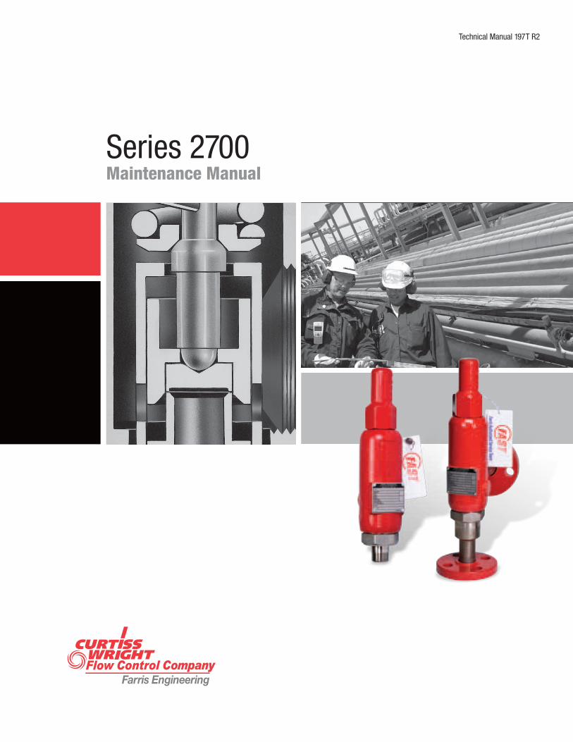
Technical Manual 197T R2
Series 2700Maintenance Manual
2
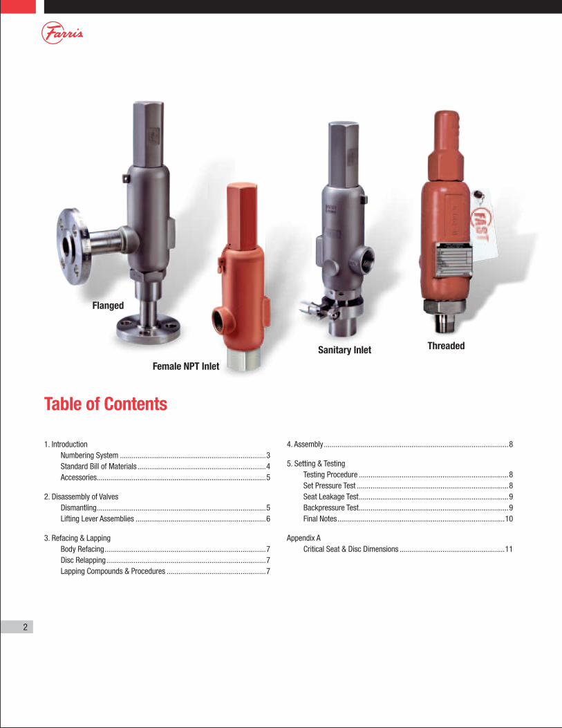
Table of Contents
1. Introduction Numbering System ...........................................................................3 Standard Bill of Materials ..................................................................4 Accessories.......................................................................................5
2. Disassembly of Valves Dismantling .......................................................................................5 Lifting Lever Assemblies ...................................................................6
3. Refacing & Lapping Body Refacing ...................................................................................7 Disc Relapping ..................................................................................7 Lapping Compounds & Procedures ...................................................7
4. Assembly ...............................................................................................8
5. Setting & Testing Testing Procedure .............................................................................8 Set Pressure Test ..............................................................................8 Seat Leakage Test .............................................................................9 Backpressure Test .............................................................................9 Final Notes ......................................................................................10
Appendix A Critical Seat & Disc Dimensions ......................................................11
Flanged
Threaded
Female NPT Inlet
Sanitary Inlet
3
Teflon is a registered trademark of the DuPont Company.Monel is a registered trademark of Inco Alloys International Inc.Hastelloy and Hastelloy C are registered trademarks of Haynes International Inc.
1. IntroductionNumbering System
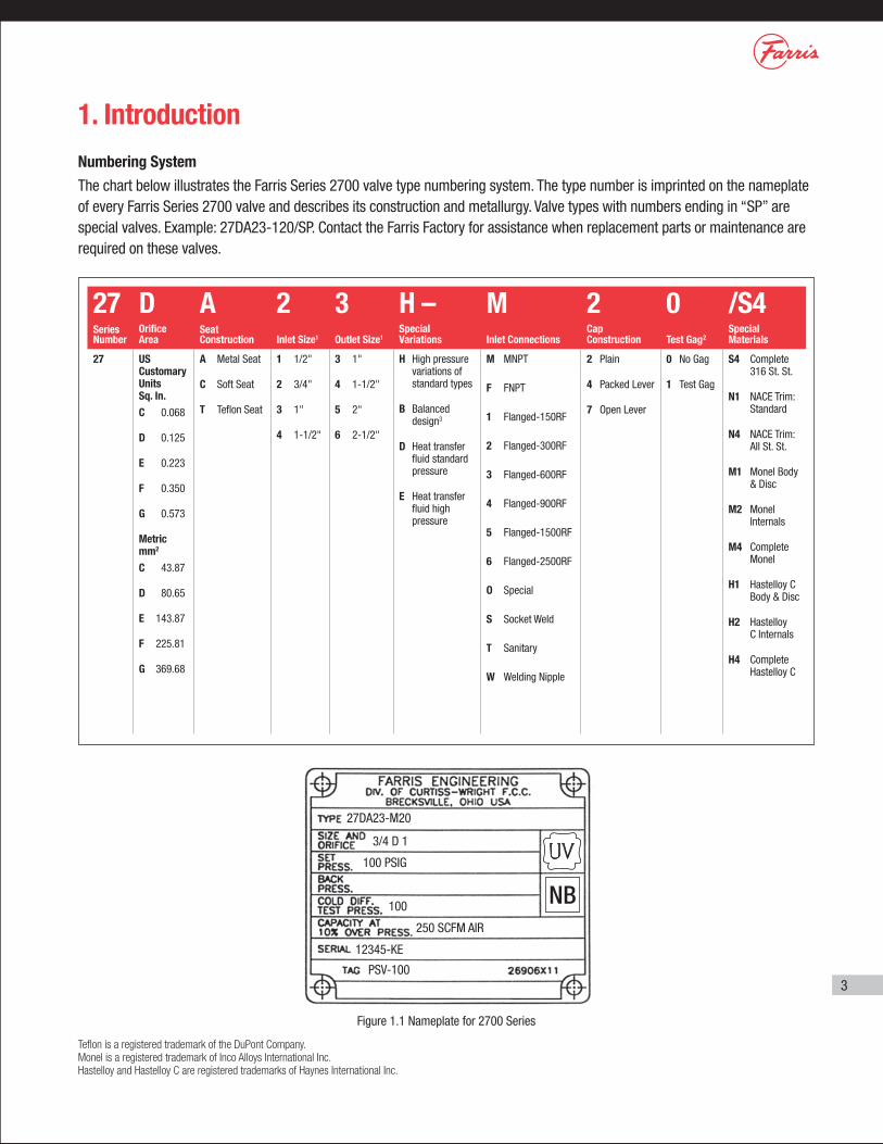
The chart below illustrates the Farris Series 2700 valve type numbering system. The type number is imprinted on the nameplate of every Farris Series 2700 valve and describes its construction and metallurgy. Valve types with numbers ending in “SP” are special valves. Example: 27DA23-120/SP. Contact the Farris Factory for assistance when replacement parts or maintenance are required on these valves.
27DA23-M20
3/4 D 1
100 PSIG
100
12345-KE
250 SCFM AIR
PSV-100
Figure 1.1 Nameplate for 2700 Series
27 D A 2 3 H – M 2 0 /S4Series Number
Orifice Area
Seat Construction Inlet Size1 Outlet Size1
Special Variations Inlet Connections
Cap Construction Test Gag2
Special Materials
27 US Customary Units Sq. In.
C 0.068
D 0.125
E 0.223
F 0.350
G 0.573
Metric mm2
C 43.87
D 80.65
E 143.87
F 225.81
G 369.68
A Metal Seat
C Soft Seat
T Teflon Seat
1 1/2"
2 3/4"
3 1"
4 1-1/2"
3 1"
4 1-1/2"
5 2"
6 2-1/2"
H High pressure variations of standard types
B Balanced design3
D Heat transfer fluid standard pressure
E Heat transfer fluid high pressure
M MNPT
F FNPT
1 Flanged-150RF
2 Flanged-300RF
3 Flanged-600RF
4 Flanged-900RF
5 Flanged-1500RF
6 Flanged-2500RF
O Special
S Socket Weld
T Sanitary
W Welding Nipple
2 Plain
4 Packed Lever
7 Open Lever
0 No Gag
1 Test Gag
S4 Complete 316 St. St.
N1 NACE Trim: Standard
N4 NACE Trim: All St. St.
M1 Monel Body & Disc
M2 Monel Internals
M4 Complete Monel
H1 Hastelloy C Body & Disc
H2 Hastelloy C Internals
H4 Complete Hastelloy C
4
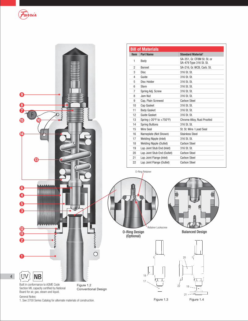
Bill of MaterialsItem Part Name Standard Material1
1 Body SA-351, Gr. CF8M St. St. or SA-479 Type 316 St. St.
2 Bonnet SA-216, Gr. WCB, Carb. St.
3 Disc 316 St. St.
4 Guide 316 St. St.
5 Disc Holder 316 St. St.
6 Stem 316 St. St.
7 Spring Adj. Screw 316 St. St.
8 Jam Nut 316 St. St.
9 Cap, Plain Screwed Carbon Steel
10 Cap Gasket 316 St. St.
11 Body Gasket 316 St. St.
12 Guide Gasket 316 St. St.
13 Spring (-20°F to +750°F) Chrome Alloy, Rust Proofed
14 Spring Buttons 316 St. St.
15 Wire Seal St. St. Wire / Lead Seal
16 Nameplate (Not Shown) Stainless Steel
17 Welding Nipple (Inlet) 316 St. St.
18 Welding Nipple (Outlet) Carbon Steel
19 Lap Joint Stub End (Inlet) 316 St. St.
20 Lap Joint Stub End (Outlet) Carbon Steel
21 Lap Joint Flange (Inlet) Carbon Steel
22 Lap Joint Flange (Outlet) Carbon Steel
Built in conformance to ASME Code Section VIII, capacity certified by National Board for air, gas, steam and liquid.
9
87
6
4
1211
5
3
2
1
10
13
15
14
O-Ring Design (Optional)
Balanced Design
Figure 1.2 Conventional Design
O-Ring Retainer
Figure 1.3 Figure 1.4
18
17
20
22 19
21
Retainer Lockscrew
General Notes:1. See 2700 Series Catalog for alternate materials of construction.
5
Dismantling1. Place the valve at a suitable height. The work surface should be clean,
and strong enough to handle the weight of the parts and the forces required during disassembly and assembly.
2. Mount valve vertically in a vise using the flats on the valve body.
3. Remove wire seal. Unscrew cap by turning counter-clockwise. (For packed and open lever cap construction, refer to the section on Lifting Lever Assemblies, pg 6.) Remove the cap gasket.
4. Using a smooth jaw wrench, hold the spring adjusting screw and remove the jam nut (spring adjusting screw).
5. Measure the distance from the top of the spring adjusting screw to the top of the bonnet, or count the number of turns of the spring adjusting screw. Use this measurement when reassembling the valve to approximately duplicate the original set pressure.
6. Remove the spring adjusting screw by turning counterclockwise.
7. Thread a pipe into the outlet and turn the bonnet counterclockwise, removing it from the body. Alternatively, the bonnet can be held in a vise and a wrench can be used on the body to loosen it.
8. Lift out the stem with spring and buttons attached. Remove upper button, spring and lower button from stem.
9. Remove the guide gasket.
10. Remove the body and trim assembly from the vise. Place one hand on top of the guide and invert the assembly, allowing the guide which contains the disc holder and disc to drop free of the body. Turn the guide upright and allow the disc holder to slide out of the guide, being careful not to drop either piece. Remove disc from disc holder and body gasket from the body.
11. Clean all parts and threaded surfaces thoroughly. Replace all gaskets.
12. Lap the body seat and disc surfaces. See Section 3 for lapping procedure and Appendix A for critical dimensions.
2. Disassembly of Valves
6
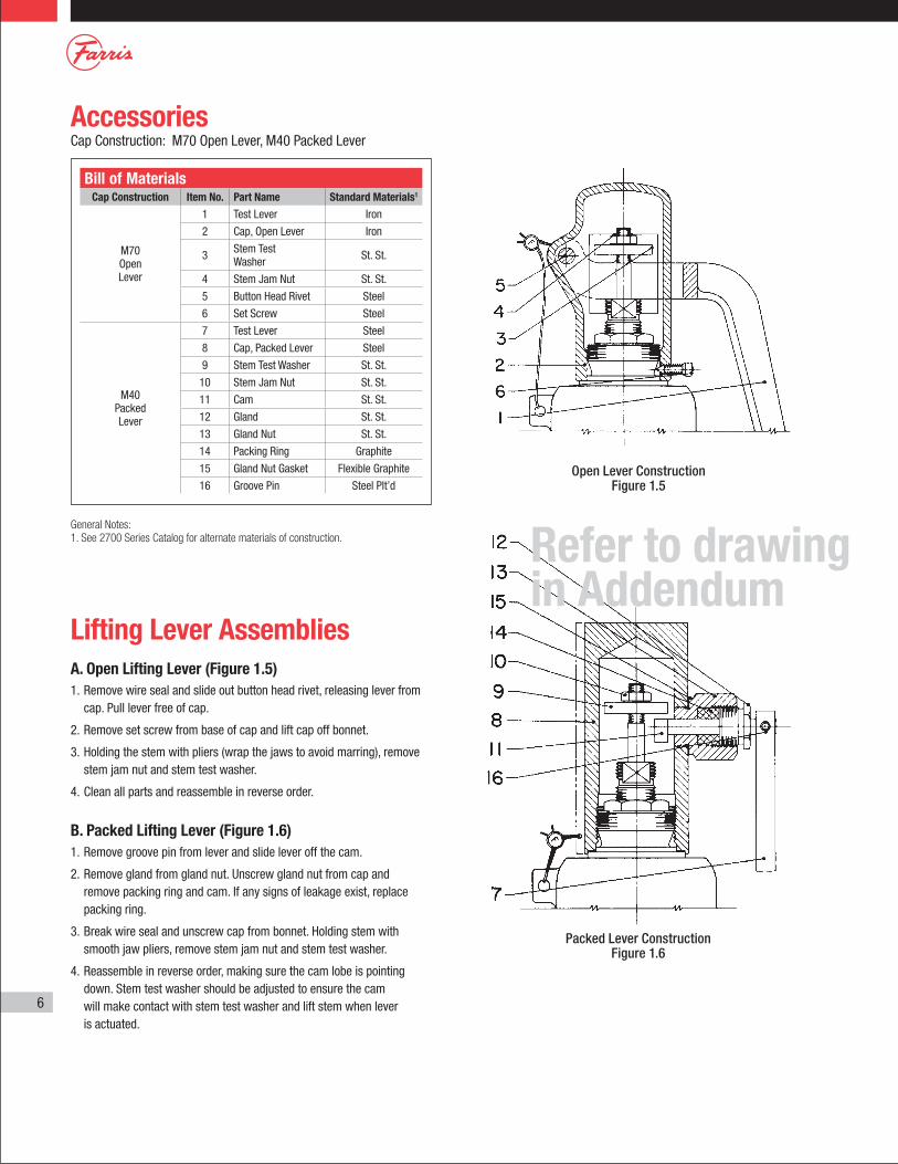
Lifting Lever AssembliesA. Open Lifting Lever (Figure 1.5)1. Remove wire seal and slide out button head rivet, releasing lever from
cap. Pull lever free of cap.
2. Remove set screw from base of cap and lift cap off bonnet.
3. Holding the stem with pliers (wrap the jaws to avoid marring), remove stem jam nut and stem test washer.
4. Clean all parts and reassemble in reverse order.
B. Packed Lifting Lever (Figure 1.6)1. Remove groove pin from lever and slide lever off the cam.
2. Remove gland from gland nut. Unscrew gland nut from cap and remove packing ring and cam. If any signs of leakage exist, replace packing ring.
3. Break wire seal and unscrew cap from bonnet. Holding stem with smooth jaw pliers, remove stem jam nut and stem test washer.
4. Reassemble in reverse order, making sure the cam lobe is pointing down. Stem test washer should be adjusted to ensure the cam will make contact with stem test washer and lift stem when lever is actuated.
Bill of MaterialsCap Construction Item No. Part Name Standard Materials1
M70 Open Lever
1 Test Lever Iron
2 Cap, Open Lever Iron
3 Stem Test Washer St. St.
4 Stem Jam Nut St. St.
5 Button Head Rivet Steel
6 Set Screw Steel
M40 Packed Lever
7 Test Lever Steel
8 Cap, Packed Lever Steel
9 Stem Test Washer St. St.
10 Stem Jam Nut St. St.
11 Cam St. St.
12 Gland St. St.
13 Gland Nut St. St.
14 Packing Ring Graphite
15 Gland Nut Gasket Flexible Graphite
16 Groove Pin Steel Plt’d
AccessoriesCap Construction: M70 Open Lever, M40 Packed Lever
General Notes:1. See 2700 Series Catalog for alternate materials of construction.
Open Lever ConstructionFigure 1.5
Packed Lever ConstructionFigure 1.6
Refer to drawing in Addendum
7
3. Refacing and Lapping
Table 1
Body Refacing (when necessary)
1. True up body by means of an indicator, ensuring that body bore and outside diameter are concentric with each other within 0.002" full indicator reading.
2. Machine a light cut across the seat until damaged areas are removed. The seat should be machined to the smoothest possible finish. Rigidity of the cutting tool is critical.
3. Relap to a mirror finish.
4. Discard and replace the body when the minimum requirement on dimension B, listed in Appendix A, is not met.
5. Bodies on O-ring seat valves do not require refacing. Contact surfaces should be cleaned of any dirt or scale and lightly lapped.
Disc Relapping (metal and Teflon discs)
1. The disc should not be refaced, only relapped.
2. Discard and replace the disc when disc thickness becomes less than dimension A, listed in Appendix A1.
Lapping CompoundsThe three grades of Farris Lapping Compounds are prepared especially for the requirements of pressure relief valves. These are the only compounds recommended for achieving extreme valve tightness.
Farris Lapping CompoundsPart No. Grade Finish Size
18632X1(055) 3F Roughing 1/2-oz. tube
18633X1(075) 38-500 Medium 1/2-oz. tube
18634X1(105) 38-1200 Final 1/2-oz. tube
Lapping Procedures (manual)
1. Use a cast iron lapping block or Pyrex lapping glass which is known to have a perfectly flat face.
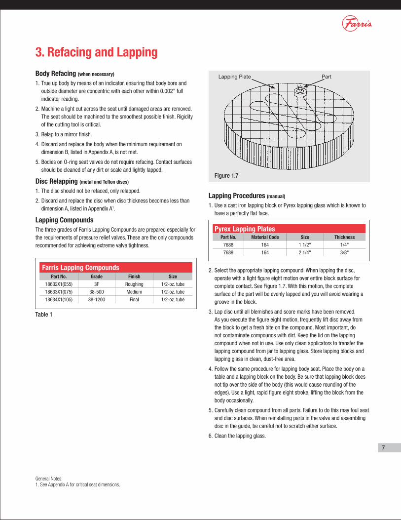
2. Select the appropriate lapping compound. When lapping the disc, operate with a light figure eight motion over entire block surface for complete contact. See Figure 1.7. With this motion, the complete surface of the part will be evenly lapped and you will avoid wearing a groove in the block.
3. Lap disc until all blemishes and score marks have been removed. As you execute the figure eight motion, frequently lift disc away from the block to get a fresh bite on the compound. Most important, do not contaminate compounds with dirt. Keep the lid on the lapping compound when not in use. Use only clean applicators to transfer the lapping compound from jar to lapping glass. Store lapping blocks and lapping glass in clean, dust-free area.
4. Follow the same procedure for lapping body seat. Place the body on a table and a lapping block on the body. Be sure that lapping block does not tip over the side of the body (this would cause rounding of the edges). Use a light, rapid figure eight stroke, lifting the block from the body occasionally.
5. Carefully clean compound from all parts. Failure to do this may foul seat and disc surfaces. When reinstalling parts in the valve and assembling disc in the guide, be careful not to scratch either surface.
6. Clean the lapping glass.
Pyrex Lapping PlatesPart No. Material Code Size Thickness
7688 164 1 1/2" 1/4"
7689 164 2 1/4" 3/8"
Figure 1.7
PartLapping Plate
General Notes:1. See Appendix A for critical seat dimensions.
8
4. Assembly 5. Setting & Testing1. Refer to Figure 1.2 for construction details, and Figures 1.5 and 1.6 for
open lever and packed lever cap construction details.
2. Verify that all parts required are grouped for assembly. Visually inspect all parts, paying close attention so that the body and disc seats are clear of imperfections and all parts are clean. Special attention should also be given to the guide, checking for any dirt or scale in exit holes and undercuts, and making sure that guide surface is in good condition.
3. All threaded surfaces should be lubricated with Bostik Never-Seez or equivalent. Sealing surfaces, such as body and cap gasket, should be lightly coated with a pipe thread sealant such as Never Seez® or equivalent.
Sliding and bearing surfaces such as disc holder/guide and disc-to-disc holder contact surfaces should be left clean and assembled without lubricants.
4. Place disc in disc holder, making sure V-notch is facing the stem radius. Insert assembly into guide. Install body gasket on the body.
5. Hold guide/disc holder assembly horizontally in your left hand and insert body, being careful not to damage disc or body seating surfaces.
6. Mount body/guide assembly vertically in a vise, gripping body securely by the flats. Install guide gasket on top of guide flange.
7. Place spring and spring buttons onto stem assembly and insert into disc holder. Hold in place in vertical position.
8. Place bonnet over assembled parts and screw down handtight onto the body. For C and D orifices, torque the bonnet to the body to 140-160 ft. lbs. For E, F, and G orifices, torque should be 180-200 ft. lbs.
9. Thread the jam nut onto the spring adjusting screw. Place spring adjusting screw over stem and into bonnet. Hand tighten spring adjusting screw until it contacts spring and lightly compresses it. Compress spring to the same point as in disassembly, if same set pressure is required. Install cap gasket.
10. Test the valve according to the procedure described in Section 5. After testing, install the appropriate cap or lever assembly.
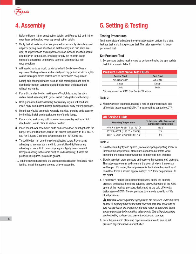
Pressure Relief Valve Test Fluids Service Fluid Test Fluid
Air, gas & vapor Air or gas
Steam Steam*
Liquid Water
*air may be used for ASME Code Section VIII valves.
Table 2
Testing ProceduresTesting consists of adjusting the valve set pressure, performing a seat leakage test and a backpressure test. The set pressure test is always performed first.
Set Pressure Test1. Set pressure testing must always be performed using the appropriate
test fluid shown in Table 2.
2. Mount valve on test stand, making a note of set pressure and cold differential test pressure (CDTP). The valve will be set at the CDTP.
3. Hold the stem tightly and tighten (clockwise) spring adjusting screw to increase the set pressure. Make sure stem does not rotate while tightening the adjusting screw as this can damage seat and disc.
4. Slowly raise test drum pressure and observe the opening (set) pressure. The set pressure on air and steam is the point at which it makes an audible pop. For water, the set pressure is the first continuous flow of liquid that forms a stream approximately 1/16" thick perpendicular to the outlet.
5. If necessary, reduce test drum pressure 25% below the opening pressure and adjust the spring adjusting screw. Repeat until the valve opens at the required pressure, designated as the cold differential test pressure (CDTP). The set pressure tolerance is equal to +/-3% of set pressure.
Caution: Never adjust the spring when the pressure under the valve is near its popping point as the body seat and disc may score and/or gall. Always lower the pressure in the test vessel at least 25% below popping pressure before making adjustments. This will put a loading on the seating surfaces and prevent rotation and damage.
6. Lock the jam nut in place and pop valve once more to ensure set pressure adjustment was not disturbed.
All Service Fluids Operating Temperature % Increase in Set Pressure at
Atmospheric Temperature
-450°F to 300°F (-268 °C to 149 °C) None
301°F to 600°F (-150 °C to 316 °C) 1%
601°F to 750°F (316 °C to 399 °C) 2%
Table 3
9
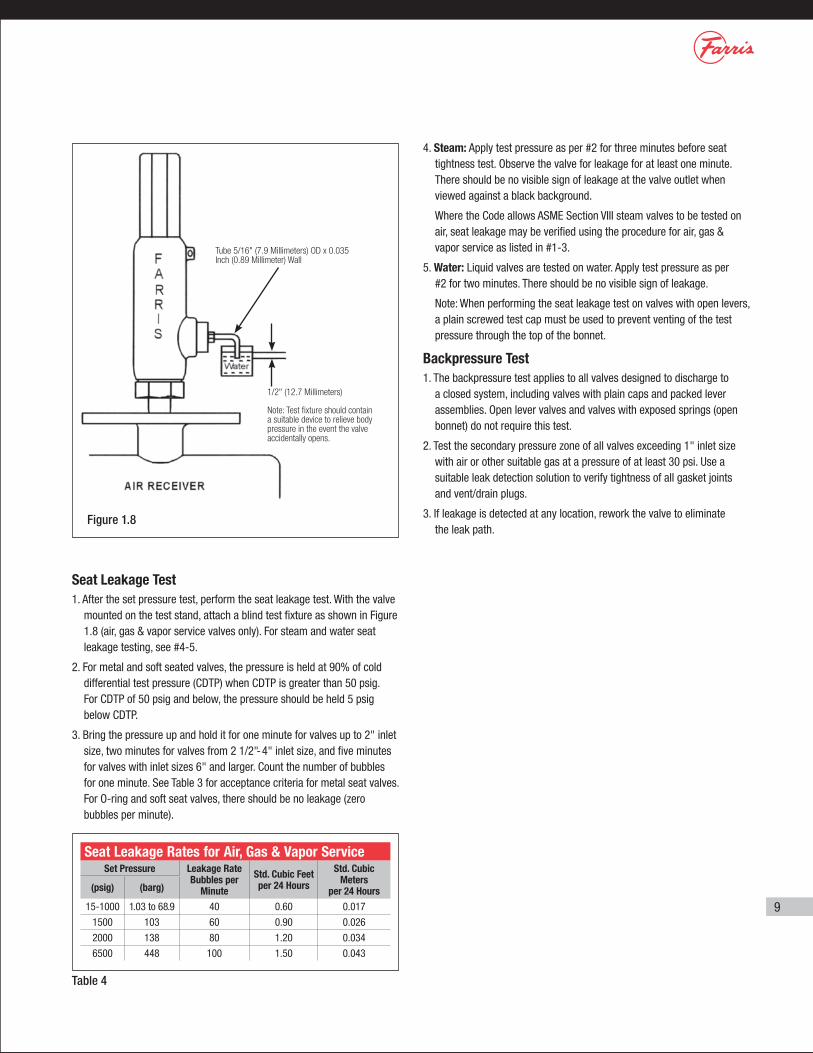
Seat Leakage Test1. After the set pressure test, perform the seat leakage test. With the valve
mounted on the test stand, attach a blind test fixture as shown in Figure 1.8 (air, gas & vapor service valves only). For steam and water seat leakage testing, see #4-5.
2. For metal and soft seated valves, the pressure is held at 90% of cold differential test pressure (CDTP) when CDTP is greater than 50 psig. For CDTP of 50 psig and below, the pressure should be held 5 psig below CDTP.
3. Bring the pressure up and hold it for one minute for valves up to 2" inlet size, two minutes for valves from 2 1/2"-4" inlet size, and five minutes for valves with inlet sizes 6" and larger. Count the number of bubbles for one minute. See Table 3 for acceptance criteria for metal seat valves. For O-ring and soft seat valves, there should be no leakage (zero bubbles per minute).
Figure 1.8
Tube 5/16" (7.9 Millimeters) OD x 0.035 Inch (0.89 Millimeter) Wall
1/2" (12.7 Millimeters)
Note: Test fixture should contain a suitable device to relieve body pressure in the event the valve accidentally opens.
4. Steam: Apply test pressure as per #2 for three minutes before seat tightness test. Observe the valve for leakage for at least one minute. There should be no visible sign of leakage at the valve outlet when viewed against a black background.
Where the Code allows ASME Section VIII steam valves to be tested on air, seat leakage may be verified using the procedure for air, gas & vapor service as listed in #1-3.
5. Water: Liquid valves are tested on water. Apply test pressure as per #2 for two minutes. There should be no visible sign of leakage.
Note: When performing the seat leakage test on valves with open levers, a plain screwed test cap must be used to prevent venting of the test pressure through the top of the bonnet.
Backpressure Test1. The backpressure test applies to all valves designed to discharge to
a closed system, including valves with plain caps and packed lever assemblies. Open lever valves and valves with exposed springs (open bonnet) do not require this test.
2. Test the secondary pressure zone of all valves exceeding 1" inlet size with air or other suitable gas at a pressure of at least 30 psi. Use a suitable leak detection solution to verify tightness of all gasket joints and vent/drain plugs.
3. If leakage is detected at any location, rework the valve to eliminate the leak path.
Seat Leakage Rates for Air, Gas & Vapor Service Set Pressure Leakage Rate
Bubbles per Minute
Std. Cubic Feet per 24 Hours
Std. Cubic Meters
per 24 Hours(psig) (barg)
15-1000 1.03 to 68.9 40 0.60 0.017
1500 103 60 0.90 0.026
2000 138 80 1.20 0.034
6500 448 100 1.50 0.043
Table 4
10
Final NotesOnce your valve has been assembled and tested, make sure you have completed all necessary records before placing it back in service. These records are important for the effective future use of the valve. They provide guidance as to when to retire valves and replace components as well as offer a historical record of the conditions and services under which the valve operated.
The valve should be properly installed in service or prepared for storage. If the valve is to be stored, the inlet and outlet should be covered to protect against any foreign matter entering the valve.
11
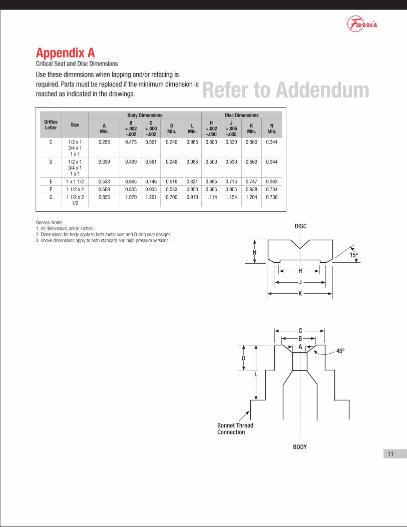
Appendix ACritical Seat and Disc Dimensions
Use these dimensions when lapping and/or refacing is required. Parts must be replaced if the minimum dimension is reached as indicated in the drawings.
General Notes:1. All dimensions are in inches.2. Dimensions for body apply to both metal seat and O-ring seat designs.3. Above dimensions apply to both standard and high pressure versions.
L
D
Bonnet Thread Connection
N
DISC
H
15º
45º
J
K
CBA
BODY
Orifice Letter Size
Body Dimensions Disc Dimensions
A Min.
B +.002 -.002
C +.000 -.002
D Min.
L Min.
H +.002 -.000
J +.005 -.005
K Min.
N Min.
C 1/2 x 1 3/4 x 1 1 x 1
0.295 0.475 0.561 0.246 0.985 0.503 0.530 0.560 0.344
D 1/2 x 1 3/4 x 1 1 x 1
0.399 0.499 0.561 0.246 0.985 0.503 0.530 0.560 0.344
E 1 x 1 1/2 0.533 0.665 0.746 0.516 0.821 0.685 0.715 0.747 0.363
F 1 1/2 x 2 0.668 0.835 0.935 0.553 0.950 0.865 0.905 0.938 0.734
G 1 1/2 x 2 1/2
0.855 1.070 1.201 0.700 0.910 1.114 1.154 1.204 0.738
Refer to Addendum
© 2010 Farris Engineering Printed in U.S.A.
11/10 3M R2
10195 Brecksville Road, Brecksville, OH 44141 USA • Telephone: 440-838-7690 • Fax: 440-838-7699 • http://farris.cwfc.comFacilities: Brecksville, Ohio, USA; Brantford, Ontario, Edmonton, Alberta, Canada; Bridport, Dorset, UK; Delhi, India; Tianjin, Beijing, China; Dubai, U.A.E.Offices Worldwide: For a listing of our global sales network, visit our website at http://farris.cwfc.com.
While this information is presented in good faith and believed to be accurate, Farris Engineering, division of Curtiss-Wright Flow Control Corporation, does not guarantee satisfactory results from reliance on such information. Nothing contained herein is to be construed as a warranty or guarantee, expressed or implied, regarding the performance, merchantability, fitness or any other matter with respect to the products, nor as a recommendation to use any product or process in conflict with any patent. Farris Engineering, division of Curtiss-Wright Flow Control Corporation, reserves the right, without notice, to alter or improve the designs or specifications of the products described herein.
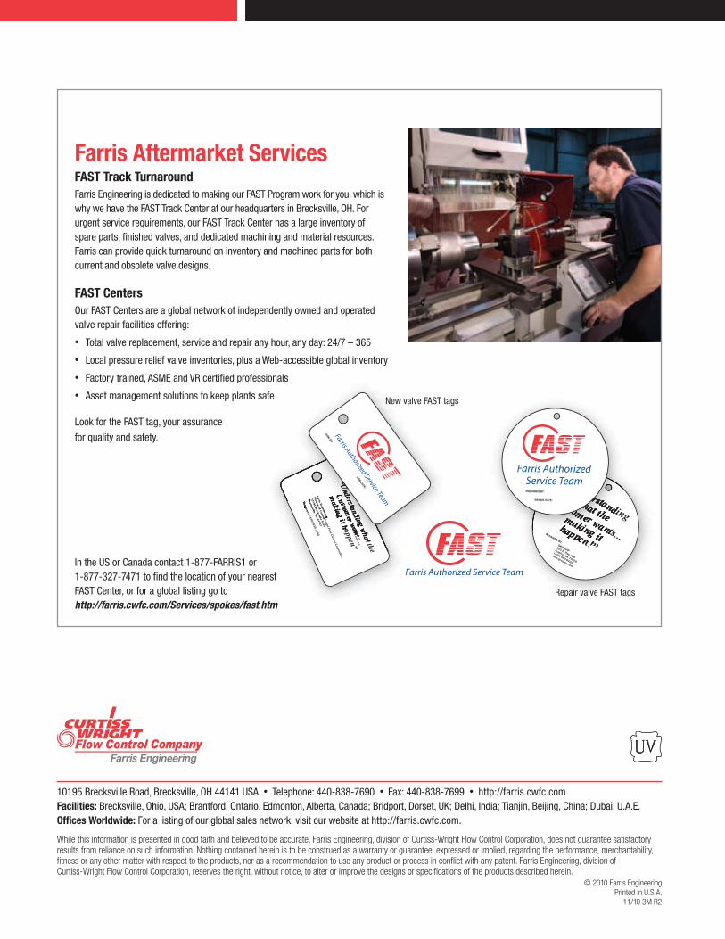
Repair valve FAST tags
New valve FAST tags
Farris Aftermarket ServicesFAST Track TurnaroundFarris Engineering is dedicated to making our FAST Program work for you, which is why we have the FAST Track Center at our headquarters in Brecksville, OH. For urgent service requirements, our FAST Track Center has a large inventory of spare parts, finished valves, and dedicated machining and material resources. Farris can provide quick turnaround on inventory and machined parts for both current and obsolete valve designs.
FAST CentersOur FAST Centers are a global network of independently owned and operated valve repair facilities offering:
• Total valve replacement, service and repair any hour, any day: 24/7 – 365
• Local pressure relief valve inventories, plus a Web-accessible global inventory
• Factory trained, ASME and VR certified professionals
• Asset management solutions to keep plants safe
Look for the FAST tag, your assurance
for quality and safety.
In the US or Canada contact 1-877-FARRIS1 or 1-877-327-7471 to find the location of your nearest FAST Center, or for a global listing go to http://farris.cwfc.com/Services/spokes/fast.htm
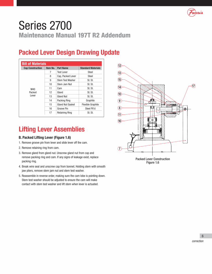
Packed Lever Design Drawing Update
Lifting Lever AssembliesB. Packed Lifting Lever (Figure 1.6)1. Remove groove pin from lever and slide lever off the cam.
2. Remove retaining ring from cam.
3. Remove gland from gland nut. Unscrew gland nut from cap and remove packing ring and cam. If any signs of leakage exist, replace packing ring.
4. Break wire seal and unscrew cap from bonnet. Holding stem with smooth jaw pliers, remove stem jam nut and stem test washer.
5. Reassemble in reverse order, making sure the cam lobe is pointing down. Stem test washer should be adjusted to ensure the cam will make contact with stem test washer and lift stem when lever is actuated.
correction
Bill of MaterialsCap Construction Item No. Part Name Standard Materials
M40 Packed Lever
7 Test Lever Steel
8 Cap, Packed Lever Steel
9 Stem Test Washer St. St.
10 Stem Jam Nut St. St.
11 Cam St. St.
12 Gland St. St.
13 Gland Nut St. St.
14 Packing Ring Graphite
15 Gland Nut Gasket Flexible Graphite
16 Groove Pin Steel Plt’d
17 Retaining Ring St. St.
Packed Lever ConstructionFigure 1.6
12
13
15
14
10
11
16
17
9
8
7
Series 2700Maintenance Manual 197T R2 Addendum
6
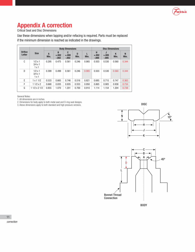
Appendix A correctionCritical Seat and Disc Dimensions
Use these dimensions when lapping and/or refacing is required. Parts must be replaced if the minimum dimension is reached as indicated in the drawings.
General Notes:1. All dimensions are in inches.2. Dimensions for body apply to both metal seat and O-ring seat designs.3. Above dimensions apply to both standard and high pressure versions.
L
D
Bonnet Thread Connection
N
DISC
H
15º
45º
J
K
CBA
BODY
Orifice Letter Size
Body Dimensions Disc Dimensions
A Min.
B +.002 -.002
C +.000 -.002
D Min.
L Min.
H +.002 -.000
J +.005 -.005
K Min.
N Min.
C 1/2 x 1 3/4 x 1 1 x 1
0.295 0.475 0.561 0.246 0.985 0.503 0.530 0.560 0.344
D 1/2 x 1 3/4 x 1 1 x 1
0.399 0.499 0.561 0.246 0.985 0.503 0.530 0.560 0.344
E 1 x 1 1/2 0.533 0.665 0.746 0.516 0.821 0.685 0.715 0.747 0.363
F 1 1/2 x 2 0.668 0.835 0.935 0.553 0.950 0.865 0.905 0.938 0.734
G 1 1/2 x 2 1/2 0.855 1.070 1.201 0.700 0.910 1.114 1.154 1.204 0.738
correction
11