Embed Size (px)
Citation preview

Series 2330MKII
Single-Phase
Adjustable-Speed
DC Motor Controllers
(1/6 – 3 HP)
BOOK0958-A


BOOK0958-ARev. 05/04
SERIES 2330 MKIISINGLE-PHASE
ADJUSTABLE-SPEEDDC MOTOR CONTROLLERS
(1/6 - 3 HP)


BOOK0958-A
iii
TABLE OF CONTENTS
SECTION TITLE PAGE
I GENERAL INFORMATION 1
Introduction 1General Description 1Model Types 1Motor Selection 2
II INSTALLATION 3
Installation Guidelines 3Installing The Controller 5Initial Startup 15
III OPERATION 16
Power On/Off 16Run 16Stop 16Speed Control 17Jog 17Reverse 17Inoperative Motor 17
IV MAINTENANCE AND REPAIR 18
General 18Adjustment Instructions 18Troubleshooting 21
V PARTS LIST 25
VI RATINGS AND SPECIFICATIONS 27
Ratings 27Operating Conditions 28Performance Characteristics 28Adjustments 29Specifications 29
VII DRAWINGS 31
INDEX 34

BOOK0958-A
iv
LIST OF TABLES
TABLE TITLE PAGE
1 Series 2330 MKII Model Matrix 12 Jumper J4 Position 53 Dip Switch (SW3) 64 Initial Potentiometer Settings 155 Dynamic Braking Characteristics 166 Troubleshooting 21-247 Parts List, Series 2330 MKII Controllers 258 Typical Application Data 279 Operating Voltages And Signals 28
10 Controller Weights 2811 Speed Regulation Characteristics 2912 Shunt Field Data 3013 Tachometer Feedback Voltage Selection 30
LIST OF ILLUSTRATIONS
FIGURE TITLE PAGE
1 Controller Mounting Configurations 72 Controller Mounting Dimensions 83 Logic Connection Diagram, Run-Stop-Jog 9
Switch4 Logic Connection Diagram, Forward-Reverse 9
Switch And Run-Stop-Jog Switch5 Logic Connection Diagram, Run-Stop Pushbuttons 10
And Run-Jog Switch,6 Logic Connection Diagram, Optional Armature 10
Contactor Reversing Using Switches7 Logic Connection Diagram, Optional Armature 11
Contactor Reversing Using Pushbuttons And Run-Jog Switch
8 Logic Connection Diagram, Line Starting With 11 Motor Speed Potentiometer
9 Signal Connection Diagram, Motor Speed 12 Potentiometer
10 Signal Connection Diagram, Tachometer Feedback 1211 Signal Connection Diagram, Current (Torque) 12
Reference Potentiometer12 Signal Connection Diagram, Line Starting Without 13
A Motor Speed Potentiometer13 Signal Connection Diagram, 4-20mA Interface 1314 Signal Connection Diagram, 4-20mA Transducer with
Auto/Manual Switch 1315 Signal Connection Diagram, Transducer with External
Burden Resistor 1416 Signal Connection, 0-10VDC External Speed Reference 1417 Functional Schematic, Series 2330 MKII 3218 Series 2330 MKII Control Board, 1/6 - 3 HP 33

BOOK0958-A
v
Blank Page

BOOK0958-A
vi
WARNING
The following must be strictly adhered to at all times.
1. YOU AS THE OWNER OR OPERATOR OF FINCOR EQUIPMENT HAVE THE RESPONSIBILITYTO HAVE THE USERS OF THIS EQUIPMENT TRAINED IN ITS OPERATIONS AND WARNED OFANY POTENTIAL HAZARDS OF SERIOUS INJURY.
2. THE DRIVE EQUIPMENT SHOULD BE INSTALLED, OPERATED, ADJUSTED, AND SERVICEDONLY BY QUALIFIED PERSONNEL FAMILIAR WITH THE CONSTRUCTION AND OPERATIONOF THE EQUIPMENT AND THE HAZARDS INVOLVED INCLUDING THOSE DESCRIBEDBELOW. FAILURE TO OBSERVE THIS WARNING CAN RESULT IN PERSONAL INJURY, LOSSOF LIFE, AND PROPERTY DAMAGE.
3. THE NATIONAL ELECTRICAL CODE REQUIRES THAT AN AC LINE FUSED DISCONNECT ORCIRCUIT BREAKER BE PROVIDED IN THE AC INPUT POWER LINES TO THE CONTROLLER.THIS DISCONNECT MUST BE LOCATED WITHIN SIGHT OF THE CONTROLLER. DO NOTOPERATE THE CONTROLLER UNTIL THIS CODE REQUIREMENT HAS BEEN MET.
4. THE DRIVE EQUIPMENT IS AT AC LINE VOLTAGE WHENEVER AC POWER IS CONNECTEDTO THE DRIVE EQUIPMENT. CONTACT WITH AN ELECTRICAL CONDUCTOR INSIDE THEDRIVE EQUIPMENT OR AC LINE DISCONNECT CAN CAUSE ELECTRIC SHOCK RESULTINGIN PERSONAL INJURY OR LOSS OF LIFE.
5. BE SURE ALL AC POWER IS DISCONNECTED FROM THE DRIVE EQUIPMENT BEFORETOUCHING ANY COMPONENT, WIRING, TERMINAL, OR ELECTRICAL CONNECTION IN THEDRIVE EQUIPMENT.
6. ALWAYS WEAR SAFETY GLASSES WHEN WORKING ON THE DRIVE EQUIPMENT.
7. DO NOT REMOVE OR INSERT CIRCUIT BOARDS, WIRES, OR CABLES WHILE AC POWER ISAPPLIED TO THE DRIVE EQUIPMENT. FAILURE TO OBSERVE THIS WARNING CAN CAUSEDRIVE DAMAGE AND PERSONAL INJURY.
8. ALL DRIVE EQUIPMENT ENCLOSURES, MOTOR FRAMES, AND REMOTE OPERATORSTATIONS MUST BE CONNECTED TO AN UNBROKEN COMMON GROUND CONDUCTOR. ANUNBROKEN GROUNDING CONDUCTOR MUST BE RUN FROM THE COMMON GROUNDCONDUCTOR TO A GROUNDING ELECTRODE BURIED IN THE EARTH OR ATTACHED TO APLANT GROUND. REFER TO THE NATIONAL ELECTRICAL CODE AND LOCAL CODES FORGROUNDING REQUIREMENTS.
9. THE ATMOSPHERE SURROUNDING THE DRIVE EQUIPMENT MUST BE FREE OFCOMBUSTIVE VAPORS, CHEMICAL FUMES, OIL VAPOR, AND ELECTRICALLY CONDUCTIVEOR CORROSIVE MATERIALS.
10. SOLID-STATE DEVICES IN THE CONTROLLER CAN BE DESTROYED OR DAMAGED BYSTATIC ELECTRICITY. THEREFORE, PERSONNEL WORKING NEAR THESE STATIC-SENSITIVE DEVICES MUST BE APPROPRIATELY GROUNDED.

BOOK0958-A
1
SECTION I
GENERAL INFORMATION
INTRODUCTION
This manual contains installation, operation, and maintenance and repair instructions for Fincor Series 2330MKII Single-Phase Adjustable-Speed DC Motor Controllers. A parts list, ratings and specifications, and drawings arealso included.
GENERAL DESCRIPTION
Series 2330 MKII Controllers statically convert AC line power to regulated DC for adjustable-speed armaturecontrol of shunt-wound and permanent-magnet motors.
Series 2330 MKII Controllers comply with applicable standards established by the National Electrical Code andNEMA for motor and industrial control equipment. The controllers are Underwriters Laboratories Listed (File No.E184521).
MODEL TYPESTABLE 1. SERIES 2330 MKII MODEL MATRIX
MODEL
FUNCTION CONFIGURATION OPERATOR CONTROLSPOWER
SOURCEa &HP RANGE
a. Units are reconnectable
RUN-STOPb
b. No armature contactor
RUN-STOP-
DBc
ARMATURESWITCH
REVERSEb
ARMATURECONTACTAND DBc
ARMATURECONTACTREVERSEAND DBc
OPENCHASSIS ENCLOSED LOCAL
INTEGRAL REMOTE 115V 230V
23312335 X X X
1/6 - 1 1/3 - 2
2331P0 X X X2331P1 X X X2331P2 X X X2331A2335A X X X X
2331AP0 X X X X2331AP3 X Xd X X2331B X X X X2331BP0 X X X X2331BP1 X X X X23322336 X X X
1/6 - 1 1/3 - 32332A2336A X X X X
2332B X X X X

BOOK0958-A
2
MOTOR SELECTION
Series 2331MKII Controllers control the operation of general purpose DC motors designed for use with solid-state rectified power supplies. The motor may be shunt-wound, stabilized shunt-wound, or permanent magnet. Formaximum efficiency, the motor should be rated for operation from a NEMA Code K power supply.

BOOK0958-A
3
SECTION II
INSTALLATION
Before starting the installation, read this section thoroughly. In addition, a through review of the Ratings AndSpecifications (Section VI) is recommended. The following installation guidelines should be kept in mind when install-ing the controller.
INSTALLATION GUIDELINES
1. CONTROLLER MOUNTING - The controller may be mounted either vertically or horizontally. However,never mount the controller upside down, immediately beside or above heat generating equipment, or directlybelow water or steam pipes.
The controller must be mounted in a location free of vibration.
Multiple controllers may be mounted side by side, as close to each other as the mounting feet will allow.
The minimum clearance at the top and bottom of the controller may be as narrow as the conduit fittings allow.
2. ATMOSPHERE - The atmosphere surrounding the controller must be free of combustible vapors, chemicalfumes, oil vapor, and electrically conductive or corrosive materials.
The air surrounding an enclosed controller must not exceed 40 degrees C (104 degrees F), and the air surround-ing an open-chassis controller must not exceed 55 degrees C (131 degrees F). Minimum air temperature is 0degree C (32 degrees F) for enclosed and open-chassis controllers.
3. CONTROLLER CONSTRUCTION - The controller base is made of die-cast aluminum with a poweredepoxy finish, and the cover is made of a die-cast aluminum alloy.
The controller enclosure is totally enclosed, nonventilated, and complies with NEMA Type 4 and 12 standards.There is an oil resistant synthetic rubber gasket between the cover and base. Those models with integral opera-tor controls include flexible boots to seal the switches, and a seal for the MOTOR SPEED potentiometer.
4. LINE SUPPLY - The controller should not be connected to a line supply capable of supplying more than100,000 amperes short-circuit current. Short-circuit current can be limited by using an input supply trans-former of 50 KVA or less, or by using correctly sized current limiting fuses in the supply line ahead of the con-troller. Do not use a transformer with less than the minimum transformer KVA listed in Table 8, page 27.
If rated line voltage is not available, a line transformer will be required. If the line supply comes directly froma transformer, place a circuit breaker or disconnect switch between the transformer secondary and the control-ler. If power is switched in the transformer primary, transients may be generated which can damage the control-ler. See Table 8 (page 27) for minimum transformer KVA.
Do not use power factor correction capacitors on the supply line to the controller.

BOOK0958-A
4
A 20-joule metal oxide varistor (MOV) is connected across the controller terminals. If higher energy transientsare present on the line supply, additional transient suppression will be required to limit transients to 150% ofpeak line voltage.
When a 115 VAC line supply is used, connect the white (common) wire to Terminal L2 and connect theremaining (hot) wire to Terminal L1.
5. ISOLATION TRANSFORMER - While not required, an isolation transformer can provide the followingadvantages:
a. Reduce the risk of personal injury if high voltage drive circuits are accidently touched.
b. Provide a barrier to externally generated AC supply transients. This can prevent controller damage fromabnormal line occurrences.
c. Reduce the potential for damaging current if the motor armature, motor field, or motor wiring becomegrounded.
6. GROUNDING - Connect the green or bare (ground) wire of the line supply to the ground screw located nearthe top conduit entry hole in the controller base. Then ground the controller base by connecting the groundscrew to earth ground.
The motor frame and operator control stations must also be grounded.
Personal injury may occur if the controller, motor, and operator stations are not properly grounded.
7. WIRING PRACTICES - The power wiring must be sized to comply with the National Electrical Code, CSA,or local codes. Refer to the controller data label for line and motor current ratings.
Do not use solid wire.
Signal wiring refers to wiring for potentiometers, tachometer generators, and transducers. Control wiring refersto wiring for operator controls, e.g., switches and pushbuttons. Signal and control wiring may be run in a com-mon conduit, but not in the same conduit as the power wiring. In an enclosure, signal and control wiring mustbe kept separated from power wiring and only cross at a 90 degree angle.
If shielded wire (such as Alpha 2422 - two conductor, 2423 - three conductor, 2424 - four conductor) is usedfor the signal and control wiring, connect the shields to chassis ground (ground screw on the controller base)and tape the opposite ends of the shields.
Two 3/4-14 NPT threaded holes are provided for conduit entry, one each in the top and bottom of the controller.

BOOK0958-A
5
INSTALLING THE CONTROLLER
1. Remove the controller front cover (if used) by removing the four cover screws.
2. Check components in the controller for shipping damage. Report shipping damage to the carrier.
3. Check the controller and motor data labels to be sure the units are electrically compatible.
4. Be sure the controller has been calibrated correctly for the motor being used. Calibration is performed bychanging the position of a Jumper (J4) on the controller control board to comply with Table 2. To change theposition of Jumper J4, pull the jumper from the control board and then push it onto the appropriate two pins onthe board. For the location of J4, see Figure 18 (page 33).
5. Check the positions of Jumpers J1, J2, and J3 on the control board. For the locations of J1, J2, and J3 , see Fig-ure 18, page 33. For a 230 VAC line supply and a 180V armature motor, Jumper J1 must be in the 230V posi-tion, and Jumpers J2 and J3 must be in the 180V position. For a 115 VAC line supply and a 90V armaturemotor, J1 must be in the 115V position, and J2 and J3 must be in the 90V position. To change the position ofJ1, J2, or J3 pull the jumper from the control board and then push it onto the appropriate pins on the board.
NOTE: If Option 1001 (Armature Contactor, Unidirectional), 1004 (Armature Contactor, Reversing), or 1775(Signal Interface) is to be installed in the controller, do not offset the five-position plug (supplied withthe option) at Connector J1 on the control board. Do not confuse Connector J1 with Jumper J1. Referto the Instruction Sheet (ISP0703, ISP0666, ISP0653, respectively) supplied with the option for con-nection instructions.
TABLE 2. JUMPER J4 POSITION
JUMPERaPOSITION
a. Select the position closed to the motor nameplate armature current rating.
MOTOR ARMATURE CURRENT RATING (AMPERES)2 HP Maximum 3 HP Maximum
100% 10 1580% 8 1260% 6 940% 4 620% 2 3

BOOK0958-A
6
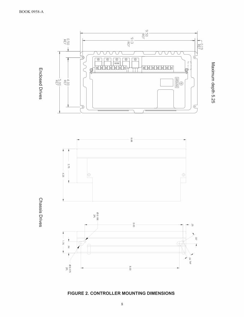
6. The controller may be surface mounted or panel mounted as shown in Figure 1, below. Mount the controller.Mounting dimensions are shown in Figure 2, page 8.
7. Conduit entry is made by punching out the knockout at the top or bottom of the controller base. To preventcomponent damage from knockout fragments, apply masking tape to the inside of the knockout before punch-ing.
8. Connect the power wiring to Terminals L1, L2, A1 (+), A2 (-), F+ and F-. Be sure to observe InstallationGuidelines 4 and 7 on pages 3 and 4. If half-wave shunt field voltage is desired, connect one of the motor shuntfield leads to Terminal F/2 (see Table 12 on page 30).
NOTE: Low inductance motors require a full-wave field to prevent current instability.
9. If the controller contains any options that require external wiring, follow the wiring instructions in the instruc-tion sheet supplied with the option.
10. If remote operator control wiring and/or signal wiring is required, connect the controller as shown in the appro-priate connection diagram (Figures 3 through 13). Figures 3 through 8 show operator control connections, andFigures 9 through 13 show signal connections.
11. The controller can be programmed for various applications by throwing switches on SW3
12. Install the controller cover, if used.
TABLE 3. DIP SWITCH (SW3)
FACTORY DEFAULT SETTING IS ALL SWITCHES “ON”Switch Position
1 ONOFF
Low Voltage (3Vdc - 30Vdc) tachometer scalingHigh voltage (31Vdc - 175Vdc) tachometer scaling.
2ONOFF
Selects internal burden resistor for 4-20ma input.Selects 0 to 5V speed reference input or external burden resistor (i.e. 10 to 50ma)
3 ONOFF
Selects internal current (torque) limit pot.Selects use of an external current (torque) limit pot.
4
ONOFF Selects Min Speed pot adjustment.
Selects Offset adjustment (for 4-20ma input) with Min Speed pot.
5
ON
OFF
Selects anti-restart mode. Prevents controller from restarting automatically after an AC line power interruption.Disables anti-restart mode. Used for line starting applications (jumper TB2:9 to TB2:8 to enable drive.

BOOK0958-A
7
FIGURE 1. CONTROLLER MOUNTING CONFIGURATIONS
BOOK 0958-A
8
FIGURE 2. CONTROLLER MOUNTING DIMENSIONS
Ma
xim
um
de
pth
5.2
5
En
clo
se
dD
rive
sC
ha
ssis
Driv
es
.34
.25
8.0
0
8.0
0
1.7
5
2.7
5
4.2
5
8.8
8
30
°
Ø0.3
75
Ø0.1
88
2PL
2PL
TYP
.94

BOOK0958-A
9
TB1
0
0
0
0
FIGURE 3. LOGIC CONNECTION DIAGRAM, RUN-STOP-JOG SWITCH
FIGURE 4. LOGIC CONNECTION DIAGRAM, FORWARD-REVERSE SWITCH AND RUN-STOP-JOGSWITCH

BOOK0958-A
10
0
0
FIGURE 5. LOGIC CONNECTION DIAGRAM, RUN-STOP PUSHBUTTONS AND RUN-JOG SWITCH
FIGURE 6. LOGIC CONNECTION DIAGRAM, OPTIONAL ARMATURE CONTACTOR REVERSINGUSING SWITCHES

BOOK0958-A
11
0
0
FIGURE 7. LOGIC CONNECTION DIAGRAM, OPTIONAL ARMATURE CONTACTOR REVERSING USING PUSHBUTTONS AND RUN-JOG SWITCH
FIGURE 8. LOGIC CONNECTION DIAGRAM, LINE STARTING WITH MOTOR SPEED POTENTIOMETER

BOOK0958-A
12
FIGURE 10. SIGNAL CONNECTION DIAGRAM, TACHOMETER FEEDBACK
FIGURE 11. SIGNAL CONNECTION DIAGRAM, CURRENT (TORQUE) REFERENCE POTENTIOMETER
FIGURE 9. SIGNAL CONNECTION DIAGRAM, MOTOR SPEED POTENTIOMETER

BOOK0958-A
13
FIGURE 12. SIGNAL CONNECTION DIAGRAM, LINE STARTING WITHOUT A MOTOR SPEED POTENTIOMETER
FIGURE 13. SIGNAL CONNECTRION DIAGRAM, 4-20 mA INTERFACE
FIGURE 14. SIGNAL CONNECTION DIAGRAM, 4-20mA TRANSDUCER WITH AUTO/MANUAL SWITCH

BOOK0958-A
14
FIGURE 15. SIGNAL CONNECTION DIAGRAM, TRANSDUCER WITH EXTERNAL BURDEN RESISTOR
FIGURE 16. SIGNAL CONNECTION, 0-10VDC EXTERNAL SPEED REFERENCE

BOOK0958-A
15
INITIAL STARTUP
1. Open the controller cover (if used) by removing the four cover screws.
2. Be familiar with all options installed in the controller by reviewing the instruction sheets supplied with theoptions.
3. Be sure all wiring is correct and all wiring terminations are tightened securely.
4. Be sure the controller is calibrated correctly. See steps 4 and 5 under “Installing The Controller” on page 5.
5. Be sure the AC supply voltage to the controller agrees with the controller data label.
6. The potentiometers in the controller are factory adjusted as shown in Table 4. These settings will provide satis-factory operation for most applications. If different settings are required, refer to “Adjustment Instructions”starting on page 18.
7. If the controller has a cover, place it on the controller and secure it with the four cover screws.
8. Turn-on the AC supply to the controller.
9. Check motor rotation, as follows:
a. If a MOTOR SPEED potentiometer is used, turn it fully counterclockwise. If an external signal is used forthe speed reference, set it at minimum.
b. If a RUN-STOP-JOG switch is used, place it in RUN position. Otherwise, initiate a Run command.
c. Turn the MOTOR SPEED potentiometer clockwise or increase the speed reference signal, as applicable.To stop the motor, place the switch in STOP position or initiate a Stop command, as applicable.
If the motor rotates in the wrong direction, turn-off the AC supply to the controller, and then interchange themotor armature leads at the motor connection box or at the controller terminal board.
10. Refer to Section III, “Operation” for operating instructions.
TABLE 4. INITIAL POTENTIOMETER SETTINGS
POTENTIOMETER SETTING DESCRIPTIONACCEL 1/3 Turn Clockwise 10 Seconds
CUR LMT Fully Clockwise (100%) 150% LoadDECEL 1/3 Turn Clockwise 10 Seconds
IR/TACH Fully Counterclockwise (0%) 0% BoostMAX SPD 3/4 Turn Clockwise 100% SpeedMIN SPD Fully Counterclockwise (0%) 0% Speed
BOOK0958-A
16
SECTION III
OPERATION
POWER ON/OFF
To energize the drive, turn-on the AC supply voltage to the controller. When this occurs, the motor shunt fieldenergizes with rated field voltage, and potentially hazardous voltage is present at the motor armature terminals. Thesevoltages can cause electric shock resulting in personal injury or loss of life.
If the AC supply is interrupted, and the controller is not set up for line starting, the motor will not restart whenthe AC supply is restored until the controller is reset by initiating a Stop command and then a Start command. If thecontroller is set up for line starting, and the AC supply is interrupted, the motor will restart when the AC supply isrestored, provided the external AC line contactor is pulled in.
RUN
If a RUN-STOP-JOG switch is used, place the switch in RUN position. Otherwise, initiate a Run command. ARun command will accelerate the motor to the setting of the MOTOR SPEED potentiometer or external speed refer-ence signal, as applicable. The rate of acceleration is preset by the ACCEL potentiometer on the controller controlboard.
STOP
If a RUN-STOP-JOG switch is used, place the switch in STOP position. Otherwise, initiate a Stop command. AStop command will stop the motor at a rate proportional to the stopping rate of the motor load.
If the controller has dynamic braking, the motor stopping time will be reduced. Dynamic braking provides expo-nential rate braking of the motor armature, which occurs when the circuit is opened between the controller and themotor armature, and one or more resistors connect across the motor armature.
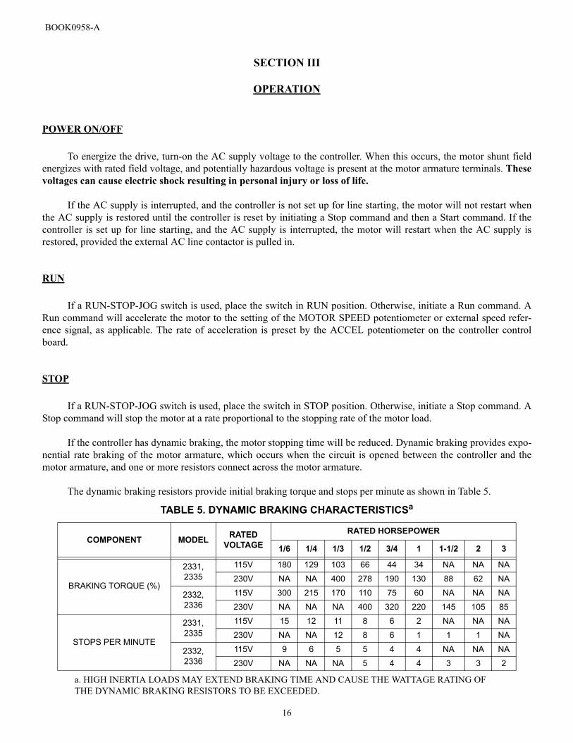
The dynamic braking resistors provide initial braking torque and stops per minute as shown in Table 5.
TABLE 5. DYNAMIC BRAKING CHARACTERISTICSa
a. HIGH INERTIA LOADS MAY EXTEND BRAKING TIME AND CAUSE THE WATTAGE RATING OF THE DYNAMIC BRAKING RESISTORS TO BE EXCEEDED.
COMPONENT MODEL RATEDVOLTAGE
RATED HORSEPOWER
1/6 1/4 1/3 1/2 3/4 1 1-1/2 2 3
BRAKING TORQUE (%)
2331,2335
115V 180 129 103 66 44 34 NA NA NA
230V NA NA 400 278 190 130 88 62 NA
2332,2336
115V 300 215 170 110 75 60 NA NA NA
230V NA NA NA 400 320 220 145 105 85
STOPS PER MINUTE
2331,2335
115V 15 12 11 8 6 2 NA NA NA
230V NA NA 12 8 6 1 1 1 NA
2332, 2336
115V 9 6 5 5 4 4 NA NA NA
230V NA NA NA 5 4 4 3 3 2

BOOK0958-A
17
An antiplug feature is included with optional Armature Contactor Reversing With Dynamic Braking (Option1004). This feature prevents restarting the motor before the motor has braked to a stop.
SPEED CONTROL
Motor speed is directly proportional to the setting of the MOTOR SPEED potentiometer or the magnitude of anexternal speed reference signal, as applicable. This potentiometer or the speed reference signal may be adjusted whilethe motor is running or may be preset before the motor is started.
The rates of acceleration and deceleration are preset by the ACCEL and DECEL potentiometers, respectively,located on the controller control board.
Maximum speed and minimum speed are preset by the MAX SPD and MIN SPD potentiometers, respectively,located on the control board.
JOG
If a RUN-STOP-JOG switch is used, place the switch in JOG position. Otherwise initiate a Jog command. Jog ismomentary, causing motor rotation only while the switch is held in JOG position or while a Jog command is active.Release the switch to stop the motor.
Normally, jog speed is directly proportional to the setting of the MOTOR SPEED potentiometer. If a separateJOG SPEED potentiometer is used, jog speed will be directly proportional to the setting of the JOG SPEED potentiom-eter.
REVERSE
To reverse motor rotation on controllers with reversing capabilities, initiate a Stop function and then initiate areversing command. The motor will then accelerate to the setting of the MOTOR SPEED potentiometer or externalspeed reference signal, as applicable. Forward and reverse speed ranges are identical.
If a FWD-REV switch is used, it must have a center position interlock, which requires a momentary relaxation ofpressure before the opposite position can be engaged. The center position causes a Stop command and allows time forthe motor to stop before a Reverse command is initiated. If a Reverse command is initiated while the motor is rotating,motor and controller damage may occur.
If Option 1004 (Armature Contactor Reversing With Dynamic Braking) is installed, an antiplug feature preventsreversing the motor before the motor has stopped.
INOPERATIVE MOTOR
If the motor stops and/or won’t start, turn-off the AC supply to the controller, remove the controller cover (ifused), and check the AC line fuse on the controller control board. For the location of the fuse, see Figure 18, page 33. Ifthe fuse is blown, refer to the Troubleshooting Table (Table 6).

BOOK0958-A
18
SECTION IV
MAINTENANCE AND REPAIR
GENERAL
1. Keep the controller dry and free of dust, dirt, and debris. No parts require periodic replacement.
2. Periodically turn-off the AC line supply to the controller and check all wire terminations to be sure they aretight.
3. Visually check components for damage due to overheating or breakage. All damaged and/or faulty componentsmust be replaced for satisfactory operation.
4. Maintain the motor according to maintenance instructions supplied by the motor manufacturer.
ADJUSTMENT INSTRUCTIONS
ACCELERATION
1. Set the MOTOR SPEED potentiometer at 100% or the external speed reference signal at maximum, as applica-ble.
2. Initiate a Run command and observe the time required for the motor to reach maximum speed.
3. Adjust the ACCEL potentiometer for the desired rate. Full counter clockwise rotation is the fastest acceleration(0.1 second), and full clockwise rotation is the slowest acceleration (30 seconds).
DECELERATION
1. With the motor running at maximum speed, quickly reset the MOTOR SPEED potentiometer to zero, orquickly decrease the speed reference signal to minimum, as applicable, and observe the time required for themotor to reach minimum speed.
2. Adjust the DECEL potentiometer for the desired rate. Full counter clockwise rotation is the fastest deceleration(0.1 second), and full clockwise rotation is the slowest deceleration (30 seconds).
IR COMPENSATION
IR compensation is used only for armature feedback. The IR/COMP potentiometer is factory set at zero (fullcounterclockwise rotation) for satisfactory operation with most motors. If improved speed regulation is desired, read-just IR compensation as follows:

BOOK0958-A
19
1. If the motor is shunt-wound, run it at rated base speed. If the motor is a permanent-magnet type, run it at about1/3 speed.
2. Turn the IR/COMP potentiometer clockwise slowly until motor speed becomes unstable. Then turn the potenti-ometer counterclockwise until motor speed stabilizes.
MAXIMUM SPEED
The MAX SPD potentiometer is factory set to provide 90 VDC armature voltage with a 115 VAC line, or 180VDC armature voltage with a 230 VAC line.
To readjust maximum speed, run the motor at maximum speed and adjust the MAX SPD potentiometer for thedesired maximum speed.
NOTE: If the MAX SPD potentiometer is turned too far counterclockwise, speed instability may occur.
MINIMUM SPEED
1. Turn the MIN SPD potentiometer fully counterclockwise (0%) for zero speed.
2. Set the MOTOR SPEED potentiometer at 0% or the external speed reference signal at minimum, as applicable.
3. Initiate a Run command and adjust the MIN SPD potentiometer for the desired minimum speed (adjustablefrom 0 to 40% of motor base speed).
CURRENT LIMIT
1. Turn the CUR LMT potentiometer fully clockwise (100%) to limit motor armature current at 150% of rated.
2. Turn the CUR LMT potentiometer counterclockwise to reduce maximum motor armature current.
NOTE:An external 5K ohm Current (Torque) Limit potentiometer can be used as shown in Figure 11 on page12. Dip switch S3 position 3 must be in the OFF position if an external Current (Torque) Limit potentiometer is desired.
3. The GREEN power on LED indicator will change to RED whenever the controller is limiting (or regulating)current to the motor.
BOOK0958-A
20
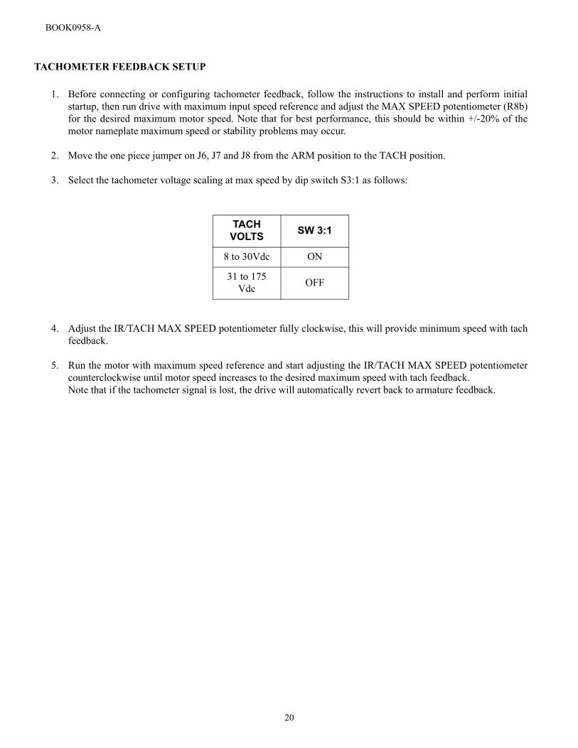
TACHOMETER FEEDBACK SETUP
1. Before connecting or configuring tachometer feedback, follow the instructions to install and perform initialstartup, then run drive with maximum input speed reference and adjust the MAX SPEED potentiometer (R8b)for the desired maximum motor speed. Note that for best performance, this should be within +/-20% of themotor nameplate maximum speed or stability problems may occur.
2. Move the one piece jumper on J6, J7 and J8 from the ARM position to the TACH position.
3. Select the tachometer voltage scaling at max speed by dip switch S3:1 as follows:
4. Adjust the IR/TACH MAX SPEED potentiometer fully clockwise, this will provide minimum speed with tachfeedback.
5. Run the motor with maximum speed reference and start adjusting the IR/TACH MAX SPEED potentiometercounterclockwise until motor speed increases to the desired maximum speed with tach feedback.Note that if the tachometer signal is lost, the drive will automatically revert back to armature feedback.
TACH VOLTS SW 3:1
8 to 30Vdc ON
31 to 175 Vdc OFF

BOOK0958-A
21
TROUBLESHOOTING
TABLE 6. TROUBLESHOOTING
INDICATION POSSIBLE CAUSE CORRECTIVE ACTION
1. Motor won’t start(See “Inoperative Motor,” page 17)
AC line open Be sure rated AC line voltage is applied to the controller.
Operator controls inoperative or con-nected incorrectly Repair accordingly.
Open circuit between Connectors E1 and E2
A wire jumper or switch must connect E1 to E2.
Controller not reset Initiate a Stop command and then a Start com-mand.
Line Voltage Selection Jumper J1 in wrong position
See Step 5 on page 5 under, “Installing The Controller.”
Controller not enabled Be sure +24 VDC is applied to Terminal TB2-8.
Loss of speed reference signal Check for 0 - 10 VDC speed reference signal.
Controller not adjusted correctly Turn the ACCEL and CUR LMT potentiome-ters fully counterclockwise (100%).
Open shunt field winding or wiring to the motor shunt field, causing loss of torquea
Check the motor shunt field and associated circuitry for a loose connection or a broken wire. Repair accordingly.
Motor failure Repair or replace the motor.
Control board failure Replace the control board.
2. Controller line fuse blows when AC line power is applied to the controller
Wiring faulty or incorrect Check all external wiring terminating in the controller. Correct accordingly.
Circuit, component, or wiring grounded Remove ground fault.
SCR1, SCR2, SCR3 or SCR4 shorted Replace shorted SCR’s or the control board.
Bridge Diode D1b shorted Replace shorted diode or the control board.
Varistor RV1 shorted Replace RV1 or the control board.
Shunt Field Diode D39, D40, D41, or D42 shorteda Replace shorted diode or the control board.
Motor shunt field shorted or groundeda Repair or replace the motor.
Control board failure Replace the control board.
Cont’d on next page

BOOK0958-A
22
3. Controller line fuse blows when a Start com-mand is initiated
One or more SCR‘s or Diode D1b shorted Replace shorted devices or the control board.
Motor shorted or grounded Repair or replace the motor.
Control board failure causing SCR’s to turn-on fully Replace the control board.
4. Controller line fuse blows while the motor is running
Motor overloaded
Check shunt field current.a Low shunt field current causes excessive armature current. If field current is adequate, check for a mechani-cal overload. If the unloaded motor shaft does not rotate freely, check motor bearings. Also check for a shorted motor armature. Motor overload can also be caused by incorrect gear ratio. Correct accordingly.
Loose or corroded connection. Wiring faulty, incorrect, or grounded
Check all terminals, connections, and wiring between the line, controller, and motor.
Motor shorted or grounded Repair or replace the motor.
One or more SCR‘s or Diode D1b breaking down (shorting intermit-tently)
Replace faulty devices or the control board.
Control board failure causing SCR false firing or misfiring Replace the control board.
5. Minimum speed exces-sive
Minimum speed not adjusted correctly Turn the MIN SPD potentiometer counter-clockwise.
Motor armature grounded Correct ground fault.
Control board failure Replace the control board.
6. Maximum speed excessive
Maximum speed set too high Turn the MAX SPD potentiometer counter-clockwise.
Controller not calibrated correctly Refer to Steps 4 and 5 on page 5.
Open shunt field winding or wiring to the motor shunt fielda
Check the motor shunt field and associated circuitry for a loose connection or a broken wire. Repair accordingly.
Motor field demagnetizedb Replace the motor.
TABLE 6. TROUBLESHOOTING
INDICATION POSSIBLE CAUSE CORRECTIVE ACTION
Cont’d on next page

BOOK0958-A
23
7. Motor won’t reach top speed
Low line voltage Check for rated line voltage, ±10%, on the controller line terminals.
Motor overloaded
Check shunt field current.a Low shunt field current causes excessive armature current. If field current is adequate, check for a mechani-cal overload. If the unloaded motor shaft does not rotate freely, check motor bearings. Also check for a shorted motor armature. Motor overload can also be caused by incorrect gear ratio. Correct accordingly.
Maximum speed set too low Turn the MAX SPD potentiometer clockwise.
Current limit set too low Turn the CUR LMT potentiometer clockwise.
Current scaling jumper J4 in wrong position See Step 4 and Table 2 on page 5.
Motor field demagnetizedb Replace the motor.
Control board failure Replace the control board.
8. Unstable speed
AC line voltage fluctuatingObserve line voltage with a voltmeter or oscil-loscope. If fluctuations occur, correct condi-tion accordingly.
Loose or corroded connection. Wiring faulty, incorrect, or grounded
Check all terminals, connections, and wiring between the line, operator controls, controller, and motor.
Oscillating load connected to the motor
Stabilize the load. Turning the IR/TACH potentiometer counterclockwise may mini-mize oscillations.
Voltage Selection Jumpers J1, J2 or J3 in wrong position
See Step 5 on page 5 under, “Installing The Controller.”
IR compensation not adjusted cor-rectly
See the IR Compensation adjustment instruc-tions on page 18.
Maximum speed not adjusted correctly See the Maximum Speed adjustment instruc-tions on page 19.
Motor faulty Check motor brushes. Replace if needed. Repair or replace the motor.
Tachometer generator or coupling faulty (if used) Repair accordingly.
TABLE 6. TROUBLESHOOTING
INDICATION POSSIBLE CAUSE CORRECTIVE ACTION
Cont’d on next page

BOOK0958-A
24
9. Line and motor arma-ture current excessive Motor overloaded
Check shunt field current.a Low shunt field current causes excessive armature current. If field current is adequate, check for a mechani-cal overload. If the unloaded motor shaft does not rotate freely, check motor bearings. Also check for a shorted motor armature. Motor overload can also be caused by incorrect gear ratio. Correct accordingly.
10. Shunt field current a too low
Open shunt field winding or wiring to the motor shunt field
Check the motor shunt field and associated circuitry for a loose connection or a broken wire. Repair accordingly.
Shunt field connected for incorrect voltage
Check motor rating and refer to Table 12 on page 30.
Diode D39, D40, D41, or D42 failure Replace faulty diode or the control board.
11. Shunt field current a too high
Shunt field connected for incorrect voltage
Check motor rating and refer to Table 12 on page 30.
Shunt field windings shortedMeasure the shunt field resistance and com-pare with the motor rating. Repair or replace the motor.
12. Motor thermal guard tripped (if used)
Ventilation insufficient Remove dirt, dust, and debris from the motor intake and exhaust screens.
Excessive motor load at low speed Reduce the load or increase the speed.
Line and motor armature current excessive See Indication 9.
Motor overheating from friction Check for misalignment. Realign the motor.
Shorted motor windings or faulty bear-ings Repair or replace the motor.
a. Does not apply to permanent-magnet motors.b. Does not apply to shunt-wound motors.
TABLE 6. TROUBLESHOOTING
INDICATION POSSIBLE CAUSE CORRECTIVE ACTION
Cont’d on next page

BOOK0958-A
25
SECTION V
PARTS LIST
TABLE 7. PARTS LIST, SERIES 2330 MKII CONTROLLERS
PART RATING
FINCOR PART NUMBER
MODEL2331, 2335
MODEL2332, 2336
Control Board NA 106703901 106703902
Diode D1b15A, 600V 3303207 NA
24A, 600V NA 3303292
Fuse, Line, F1 30A, 600V (ATM-30) 3002396 3002396
SCR1, SCR2,SCR3, SCR4
15A, 600V 3302201 NA
55A, 800V NA 3302231

BOOK0958-A
26
Blank Page

BOOK0958-A
27
SECTION VI
RATINGS AND SPECIFICATIONS
RATINGS
1. Duty. . . . . . . . . . . . . . . . . . . . . . . . . . . . . . . . . . . . . . . . . . . . . . . . . . . . . . . . . . . . . . . . . . . . . . . . . . . . . . . Continuous
2. Horsepower Range. . . . . . . . . . . . . . . . . . . . . . . . . . . . . . . . . . . . . . . . . . . . . . . . . 1/6 - 3 HP (See Table 1, Page 1)
3. Line Fuse Interrupting Capacity. . . . . . . . . . . . . . . . . . . . . . . . . . . . . . . . . . . . . . . . . . . . . . . . . . 100,000 Amperes
4. Line Power. . . . . . . . . . . . . . . . . . . . . . . . . . . . . . . . . . . . . . . . . . . . . . . 115V Or 230V, Single-Phase, 50 Or 60 Hz
5. Motor Speed Potentiometer. . . . . . . . . . . . . . . . . . . . . . . . . . . . . . . . . . . . . . . . . . . . . . . . . . . . . . . 5K Ohms, 1/2W
6. Overload Capacity, Armature Circuit. . . . . . . . . . . . . . . . . . . . . . . . . . . . . . . . . . . . . . . . . . . . 150% For 1 Minute
7. Timed Overload Threshold. . . . . . . . . . . . . . . . . . . . . . . . . . . . . . . . . . . . . . . . . . . . . . . . . . . . . . . . . . . . . . . . . 120%
8. Service Factor. . . . . . . . . . . . . . . . . . . . . . . . . . . . . . . . . . . . . . . . . . . . . . . . . . . . . . . . . . . . . . . . . . . . . . . . . . . 1.0
TABLE 8. TYPICAL APPLICATION DATA
COMPONENT RATINGS
RATED HORSEPOWER (HP) 1/6 1/4 1/3 1/2 3/4 1 1-1/2 2 3
RATED KILOWATTS (kW) 0.124 0.187 0.249 0.373 0.560 0.746 1.120 1.492 2.238
1-PHASE AC INPUT
(FULL-LOAD)
LineAmps
115VUnit 3.9 5.0 6.0 8.7 12.4 15.8 NA NA NA
230VUnit NA NA NA 4.2 5.9 8.8 12.6 15.8 22.0
KVA 0.48 0.58 0.71 1.00 1.40 2.00 3.00 4.00 5.00
DC OUTPUT(FULL-LOAD)
MotorArmature
Amps
90V 2.0 2.8 3.5 5.4 8.1 10.5 NA NA NA
180V NA NA NA 2.6 3.8 5.5 8.2 11.6 15.1
MotorFieldAmps
(Maximum)
Model 2331, 2335
1.0 1.0 1.0 1.0 1.0 1.0 1.0 1.0 NA
Model 2332, 2336
1.5 1.5 1.5 1.5 1.5 1.5 1.5 1.5 1.5
FULL-LOAD TORQUE (lb-ft) with 1750 RPM Base Speed Motors 0.5 0.75 1.0 1.5 2.2 3.0 4.5 6.0 9.0
MINIMUM TRANSFORMER KVA FOR VOLTAGE MATCHING OR ISOLATION 0.5 0.75 0.75 1.0 1.5 2.0 3.0 5.0 7.5

BOOK0958-A
28
OPERATING CONDITIONS
1. Altitude, Standard. . . . . . . . . . . . . . . . . . . . . . . . . . . . . . . . . . . . . . . . . . . . . . 1000 Meters (3300 Feet) Maximum1
2. Ambient Temperature. . . . . . . . . . . . . . . . . . . . . . . . . . . . . . . . . . . . . . . . . . . . . . . . . . . 0 - 40°C (32°F - 104°F)2
3. Line Frequency Variation. . . . . . . . . . . . . . . . . . . . . . . . . . . . . . . . . . . . . . . . . . . . . . . . . . . . . . .± 2 Hz Of Rated
4. Line Voltage Variation. . . . . . . . . . . . . . . . . . . . . . . . . . . . . . . . . . . . . . . . . . . . . . . . . . . . . . . . . . . . ±10% Of Rated
5. Relative Humidity. . . . . . . . . . . . . . . . . . . . . . . . . . . . . . . . . . . . . . . . . . . . . . . . . . . . . . . . . . . 95% Noncondensing
PERFORMANCE CHARACTERISTICS
1. Controlled Speed Range . . . . . . . . . . . . . . . . . . . . . . . . . . . . . . . . . . . . . . . . . . . . . . . . . . . . 0 To Motor Base Speed
2. Displacement Power Factor (Rated Speed/Rated Load). . . . . . . . . . . . . . . . . . . . . . . . . . . . . . . . . . . . . . . . . . 87%
3. Efficiency (Rated Speed/Rated Load)
a. Controller Only. . . . . . . . . . . . . . . . . . . . . . . . . . . . . . . . . . . . . . . . . . . . . . . . . . . . . . . . . . . . . . . . . . . . . . . . 98%
TABLE 10. CONTROLLER WEIGHTSCONTROLLER MODEL WEIGHT - LBS (KG)
Rated Horsepower (HP) 1/6 - 2 3
2331, 2332, 2336 3.25 (1.48)2331A, 2332A, 2336A 3.80 (1.75)
2331P0, 2331P1, 2331P2 5.50 (2.50) NA2331AP0, 2331AP3 6.05 (2.75) NA
2335 0.9 (0.42)2335A 1.7 (0.77)
1. Controller can be derated by 1% per 100 meters to operate at higher altitudes.2. 55°C (131°F) maximum in enclosed areas where open-chassis controllers are mounted.
TABLE 9. OPERATING VOLTAGES AND SIGNALS
POWER SOURCE(Single-phase)
OUTPUT VDC SPEEDREFERENCE
SIGNAL
MAGNETIC CONTROL VOLTAGEArmature Field
115V, 50 or 60 Hz 0 - 90 50/1000 - 10 VDC, 24 VDC
230V, 50 or 60 Hz 0 - 180 100/200

BOOK0958-A
29
b. Controller With Motor, Typical. . . . . . . . . . . . . . . . . . . . . . . . . . . . . . . . . . . . . . . . . . . . . . . . . . . . . . . . . . 85%
4. Speed Regulation. . . . . . . . . . . Regulation percentages are of motor base speed under steady-state conditions
TABLE 11. SPEED REGULATION CHARACTERISTICS
ADJUSTMENTS
1. Acceleration, Linear. . . . . . . . . . . . . . . . . . . . . . . . . . . . . . . . . . . . . . . . . . . . . . . . . . . . . . . . . . . . . 0.1 - 30 Seconds
2. Deceleration, Linear. . . . . . . . . . . . . . . . . . . . . . . . . . . . . . . . . . . . . . . . . . . . . . . . . . . . . . . . . . . . . 0.1 - 30 Seconds
3. IR (Load) Compensation. . . . . . . . . . . . . . . . . . . . . . . . . . . . . . . . . . . . . . . . . . . . . . . . . . . . . . . . 0 To 10% Boost
4. Jog Speed. . . . . . . . . . . . . . . . . . . . . . . . . . . . . . . . . . . . . . . . . . . . . . . . . . . . . . . . . 0 - 100% Of Motor Base Speed
5. Maximum Speed. . . . . . . . . . . . . . . . . . . . . . . . . . . . . . . . . . . . . . . . . . . . . . . . . 50% - 100% Of Motor Base Speed
6. Minimum Speed. . . . . . . . . . . . . . . . . . . . . . . . . . . . . . . . . . . . . . . . . . . . . . . . . . . . . 0 - 40% Of Motor Base Speed
7. Torque (Current) Limit. . . . . . . . . . . . . . . . . . . . . . . . . . . . . . . . . . . . . . . . . . . . . . .. 0 - 150% Of Full-Load Torque
SPECIFICATIONS
1. AC LINE PROTECTION - A 100,000 ampere interrupting capacity AC line fuse provides instantaneous pro-tection from peak loads and fault currents. This line fuse is located inside the controller.
2. AUXILIARY CONTACT - A normally-open Form A relay contact, rated .5 ampere @115 VAC and 2A at 30VDC, is available for external use. The relay energizes when a Run command is initiated, and de-energizeswhen a Normal Stop command is initiated, the overload monitor trips, or the anti-restart circuit is activated.
3. FIELD SUPPLY - A half-wave or full-wave shunt field supply is available as shown in Table 12, page 30.
REGULATIONMETHOD
VARIABLE
LoadChange(95%)
LineVoltage(±10%)
FieldHeating
(Cold/Normal)
Temperature(±10°C)
SpeedRange
Standard Voltage Feedback with IRCompensation
2% ±1% 5 - 12% ±2% 50:1
Optional Speed (Tach) Feedbacka
a. Unidirectional models only.
0.5% ±1% 0.2% ±2% 200:1

BOOK0958-A
30
TABLE 12. SHUNT FIELD DATA
4. MOTOR CONTACTOR - Controller model numbers with an ‘A’ suffix, e.g., 2331A, 2331AP0, have a DCmagnetic armature contactor, which disconnects both motor armature leads from the controller. An antiplugcircuit ensures that the contactor does not make or break DC.
5. POWER CONVERSION - The DC power bridge consists of four SCR’s, one freewheeling diode. Eachdevice is rated at least 600 PIV. The controller base forms an integral heat sink, with the power devices electri-cally isolated from the base.
6. SELECTABLE CAPABILITIES - Switches allow the user to select various modes of operation, as follows:
a. LINE STARTING - By placing SW3:5 in the OFF position, the ‘anti-restart’ feature will be disabled, andthe controller may be started and stopped with an external AC line contactor. However, a wire jumper mustbe connected between TB2-8 and TB2-9. If full speed operation is desired, connect another wire jumperbetween TB2-2 and TB2-3.
b. TACHOMETER FEEDBACK - To use tachometer feedback with armature feedback backup, connectthe tachometer generator signal to TB2-7 and TB2-5, (polarity insensitive) and select the tachometer gen-erator voltage at maximum speed by using SW3:1 as follows:
c. TORQUE REGULATOR - The controller will function as a torque regulator when SW3:3 is OFF. Thisallows an external potentiometer to set maximum motor torque (0 - 150% of rated).
7. VOLTAGE TRANSIENT PROTECTION - A metal oxide suppressor (varistor) across the AC line is com-bined with RC snubbers across the power bridge to limit potentially damaging high voltage spikes from the ACpower source.
CONTROLLER RATING(VAC)
SHUNT FIELD VOLTAGE (VDC) MOTOR SHUNT FIELD LEAD CONNECTIONS
Half-Wave Full-Wavea
a. Low inductance motors require a full-wave field to prevent speed instability.
F1 F2
11550 F/2 F-
100 F+ F-
230100 F/2 F-
200 F+ F-
TABLE 13. TACHOMETER FEEDBACK VOLTAGE SELECTIONTACH VOLTAGE SW3:1
8Vdc - 30Vdc ON31Vdc - 175 Vdc OFF

BOOK0958-A
31
SECTION VII
DRAWINGS

BOOK0958-A
32
FIG
UR
E 17
. FU
NC
TIO
NA
L SC
HEM
ATIC
, SER
IES
2330
MK
II
TB
1
L1E
1E
2
AC
1
S1-
A
AC
2
FL=
100M
V2H
P=.
01
L2 F+
F/2
F-
100/
200V
115/
230V
AC
50/1
00V
CO
M
FIE
LDC
ON
NE
CT
ION
S
A1
A2
90/1
80V
DC
2M 2M
180V
90V
J3 J2
2M 2M
89K
89K
- +324
U1A
SP
DM
AX
6.2K
0 100
80K
+324
-
U2B
200K
.1uf
FS
=4V
FS
=-5V
R5
100%
80%
60%
40%
20%
SH
UN
TIS
OLA
TO
R
8VA
C
J4C
UR
RE
NT
SC
ALI
NG
ARM
ISO
LAT
OR
1K
100K
100K
100K
ARM
BA
CK
UP
0
100
221K
S3-
1
30K
J7
U3B
- 324
+
7
TA
CH-
FL=
+1V
100K
100K
FL=
-1V
S3-
26
4-20
mA
249
IRC
OM
P/
MAX
SP
DT
AC
H
5
CO
M
3 2
+
324
-
U1D
150K
80K
200K
150K
U1B
+
324
-
1
4
AC
CE
L0.
1TO
30S
EC
AC
CE
L
2M0 0
100
100
2M
DE
CE
L
+
324
-
22uf
+
+CA
PE
XTA
CC
EL
C5
150K
0
100
150K
500K
FS=
7.5V
S3-
4
OF
FS
ET
INP
UT
MIN
SP
D5K
+10
V
5KRE
FS
PD
0
100
+10
V
100 0
CU
RR
EF
5K
+10
V
U3C
-
324
+
SP
EE
DC
ON
TR
OL
AN
DF
IRIN
GC
IRC
UIT
G1
&2
G3
G4
100K
100K
100K
LIM
CU
R
0
100
S3-
3+
10V
1M
150K
+
324
-
U2D
RE
GC
UR
RE
NT
ER
RO
RS
IGN
AL
RED
=C
UR
RE
NT
LIM
IT
GRN
=O
N
/RE
SE
T
100/
5047
/50
+
+
+24
V
-24V
-12V
+12
V
7912
7812
2K 10V
+10
V
8VA
C
20V
AC
20V
AC
AC
1
AC
2
115V
230V
230V
115V
J1
=P
OW
ERC
ON
NE
CT
IONS
TB
1
=C
US
TO
MER
INT
ER
FA
CET
B2
=O
PT
ION
CO
NN
EC
TOR
J5
=S
PA
DEC
ON
NE
CT
OR(N
OT
ON
5HP
VE
R)
F1
AT
M-3
0
90V
180V
10K
MA
XS
PD
AR
M
OP
ENF
OR
HV
TA
CH
.1uf
RE
G
CU
RR
EN
T
OP
ENF
OR
EX
TB
UR
DE
N
SIG
NA
L
RE
S
4V
OP
ENF
OR
OF
FS
ET
OP
ENF
OR
TO
RQ
UEIN
PU
T
AR
MA
TU
REV
OLT
AG
ES
ELE
CT
ION
LINE
VO
LTA
GE
SE
LEC
TIO
N
22M
-12V
R3
10
+24
V
SU
PE
RV
ISO
RY
LOG
IC
LOA
D
MO
NIT
OR
AN
TI-
RE
ST
AR
T
Q8
EN
AB
LE
S3-
5
OP
ENF
OR
LINE
ST
AR
T
119 8
J8
SPD
RE
GN
OD
E
TA
CH
AR
M
AB
SO
LUT
EV
ALU
E
J6
TA
CH
AR
M
TA
CH
AR
MJ6
,7,8
SET
BY
ON
EP
IECE
JUM
PE
R
1 2 3 4 5
6
TB
1 7
TB
1
RU
NC
OA
ST
ST
OP
2 6
3
4 8 11 9
5
7
10
12
13
14
K0
K0
SC
R1
SC
R2
SC
R3
SC
R4
1
A10
6771
5

BOOK0958-A
33FIGURE 18. SERIES 2330 MKII CONTROL BOARD, 1/6 - 3 HP
MOTO ARMATURECONNECTIONTERMINALS
MOTOR SHUNT FIELDCONNECTIONTEMINALS
AC LINECONNECTIONTERMINALS
LOGIC & SIGNALCONNECTIONTERMINALS
CURRENT LIMIT POT
ACCELERATION POT
OPTION CONNECTOR J5
DECELERATION POT
MAXIMUM SPEED POT
MINIMUM SPEED POT
SHUNT RESISTORS
AC LINE FUSE F1
CONNECTOR E1
CONNECTOR E2
IR/TACHOMETER
BI-COLOR LEDGREEN = POWER ONRED = CURRENT LIMIT
CALIBRATION POT
115/230V ACJUMPER J1(Shown in 230VPosition)
90/180V ACJUMPERS J2 & J3(Shown in 180VPosition)
MO TO RCURRENTJUMPER J4SET @ 100%
ARMA TURE/TACHFEEDBACK3POSITIONJUMPER J6,J7,J8 (Set onArmature)
5POSITION DIP SWITCH(All set in closed Position)
R
INDE X BOOK0958-A
34
AAC LINE PROTECTION 29AC supply transients 4ACCEL potentiometer 18Acceleration, Linear 29Altitude, Standard 28Ambient Temperature 28antiplug circuit 30antiplug feature 17anti-restart feature 30armature feedback backup 30ATMOSPHERE 3AUXILIARY CONTACT 29
Ccircuit breaker 3Conduit entry 6Connector J5 33Control wiring 4Controlled Speed Range 28CONTROLLER CONSTRUCTION 3CONTROLLER MOUNTING 3CSA 1, 4CUR LMT potentiometer 19Current (Torque) Limit potentiometer 19Current (Torque) Reference potentiometer 6CURRENT LIMIT 19current limiting fuses 3
DDECEL potentiometer 18Deceleration, Linear 29disconnect switch 3Displacement Power Factor (Rated Speed/Rat-
ed Load) 28Duty 27Dynamic braking 16dynamic braking resistors 16
EEfficiency (Rated Speed/Rated Load) 28electrical noise 4
FFIELD SUPPLY 29full-wave field 6fuses 3
Gground screw 4GROUNDING 4
Hhalf-wave shunt field voltage 6Horsepower Range 27
IIR (Load) Compensation 29IR/COMP potentiometer 18ISOLATION TRANSFORMER 4
JJog Speed 29JOG SPEED potentiometer 17Jumper J1, J2, J3 and J4 5
LLine Frequency Variation 28line fuse 29Line Fuse Interrupting Capacity 27Line Power 28LINE STARTING 6, 16, 30LINE SUPPLY 3Line Voltage Variation 28Low inductance motors 6
MMAX SPD potentiometer 19MAXIMUM SPEED 19, 29MIN SPD potentiometer 19MINIMUM SPEED 19, 29minimum transformer KVA 3MOTOR CONTACTOR 30motor rotation 15Motor Speed Potentiometer 27
NNational Electrical Code 1, 4NEMA 1NEMA Type 4 and 12 standards 3
OOscillating load 23Overload Capacity, Armature Circuit 27

BOOK0958-A INDE X
35
Ppower bridge 30POWER CONVERSION 30power factor correction capacitors 3power wiring 4, 6
RRelative Humidity 28
SSELECTABLE CAPABILITIES 30Service Factor 27shielded wire 4shipping damage 5Short-circuit current 3Signal wiring 4Speed Regulation 29
TTACHOMETER FEEDBACK 20, 30Torque (Current) Limit 29TORQUE REGULATOR 30transformer 3transients 3, 4twisted cable 4
UUnderwriters Laboratories Listed 1
Vvaristor 4, 30vibration 3VOLTAGE TRANSIENT PROTECTION 4,30

www. fincor.nett