Embed Size (px)
Citation preview
1752CDC110004C0202
5
Serial data convertersIPLH range
Content
Serial data converters ILPH range ............................................................................ 176NEW

176 ABB Entrelec2CDC110004C020
RS-232 RS-485
RS-232 RS-232RS-422
RS-422 RS-422
RS-422
RS-232
RS-232 RS-232 RS-232 RS-232
RS-232 RS-23215 mmax.
1.2 kmmax.
15 mmax.
1.2 kmmax.
Serial data converters
In the field of industrial data transmission, various processes of datatransmission and interfaces are used today. Thus, the user often feelsthe need to convert the existing interface into another interface.Simple point to point connections are most often made using thestandard RS-232 (V.24), and multipoint with the RS-422 or RS-485standard, with a current tendency to use optical fiber.
For the conversion of various interfaces, ABB ENTRELEC offersconnection interfaces ILPH, a large range of products for industrialuse.
Uses
Adaptation :
The use of converters allows the connection of two devices usingDifferent interfaces.To add new equipment to existing installations.
Galvanic Isolation.
To protect sensitive equipment it is sometimes necessary to useconverters which allow galvanic isolation.
Type of connection Immunity to noiseRS232 LowRS422 HighRS485 HighCL HighOF Very high
To cross a disturbed environment.
Some interfaces are more sensitive to noise. Electrically, it is preferable,in some cases, to change the interface or support.
Multipoint connections
Some equipments are only designed to communicate in RS232 pointto point connection. To communicate with several devices it is thennecessary to use converters RS232 to RS422, RS485, BDC or FO toreach multipoint mode.
Type of connection ConnectionRS232 Point to pointRS422 12 pointsRS485 32 pointsCL 5-6 pointsOF 32 points
Type of connection Max. distances *RS232 15mRS422 1.2kmRS485 1.2kmCL 300-500mOF 4km
Increase in the transmission and amplification distancesfrom the Signals.
Every connection has its own limits, to increase the communicationdistances you only have to change the type of link (converter) oramplify the signal (Repeater) using an ILPH.
* Depending on transmission speed.
Example :
Example :
Line 1
Line 2
Power
Converter Repeater
Example :
Example :
Example :
Noisyelements
RS-485 2-/4 wires

177ABB Entrelec2CDC110004C0202
• •• •
• •• •• •• •
• •• •• •
• •• •
• •• •
• •• •
• •• •
1SNA 684 234 R2000
1SNA 684 244 R0200
1SNA 684 231 R2500
1SNA 684 233 R2700
1SNA 684 333 R2300
1SNA 684 334 R2400
1SNA 684 202 R0100
1SNA 684 236 R2200
1SNA 684 237 R2300
1SNA 684 238 R0400
1SNA 684 239 R0500
1SNA 684 212 R2200
1SNA 684 232 R2600
1SNA 684 246 R0400
1SNA 684 247 R0500
1SNA 684 248 R1600
1SNA 684 249 R1700
0084 234.12
0084 244.24
0084 231.17
0084 233.11
0084 333.15
0084 334.16
0084 202.23
0084 236.14
0084 237.15
0084 238.26
0084 239.27
0084 212.14
0084 232.10
0084 246.26
0084 247.27
0084 248.00
0084 249.01
1SVR 084 236 R1400
1SVR 084 237 R1500
1SVR 084 238 R2600
1SVR 084 239 R2700
1SVR 084 246 R2600
1SVR 084 247 R2700
1SVR 084 248 R0000
1SVR 084 249 R0100
RS232
RS422 / RS485
RS485
RS2
32R
S422
-485
24 V
DC
24-4
8 V
DC
110-
240
V AC
24-4
2 V
AC/D
C
Old
ABB
pa
rt nu
mbe
rsRS 232 - EIA-232 / V.24 / V.28Point-to-point connectionMax. 15 m transmission distanceRate up to 19.2 kbit/sFull-duplex
RS 422 - EIA-422 / V.11Point-to-point connection(1 Transmitter - 10 Receivers)Differential voltage transmissionFull-duplexUp to 1200 m/ 10Mbit/sGood EMC characteristics
Current loop(TTY)Point-to-point / multi-point connectionActive or passive current loopFull-duplexUp to 1200 m/19.2 kBit/sGood EMC characteristics
RS 485 - ISO/IEC/EIA-485Multi-point connection up to 32 unitsDifferential voltage transmissionHalf-duplex on 1 pairFull-duplex on 2 pairsUp to 1200 m / 10Mbit/sGood EMC characteristics
Optical fiber interfacePoint-to-point connectionFull-duplexFrom 40m up to 4km transmission distanceaccording to optical fiber material (plastic / glass)and wavelength used up to 10 Mbit/sExcellent EMC characteristics
In-Ps-O
In-Ps-O
Wi
In-O
In-Ps-O
In-Ps-O
In-O
In-Ps-O
In-Ps-O
In-Ps-O
In-Ps-O
In-O
In-O
In-Ps-O
In-Ps-O
In-Ps-O
In-Ps-O
Insu
latio
n *
New
pa
rt nu
mbe
rs
Old
Ent
rele
c
part
num
bers
* In=Input, Ps=Power supply, O=Output, Wi=Without insulation
CL
OF-
SO
F-P
Product overview

178 ABB Entrelec2CDC110004C020
RRt E
R
E
R
E
Rt
Rt
Rt
R
E
ILPH RS 232 / RS 422-485 1 0,1
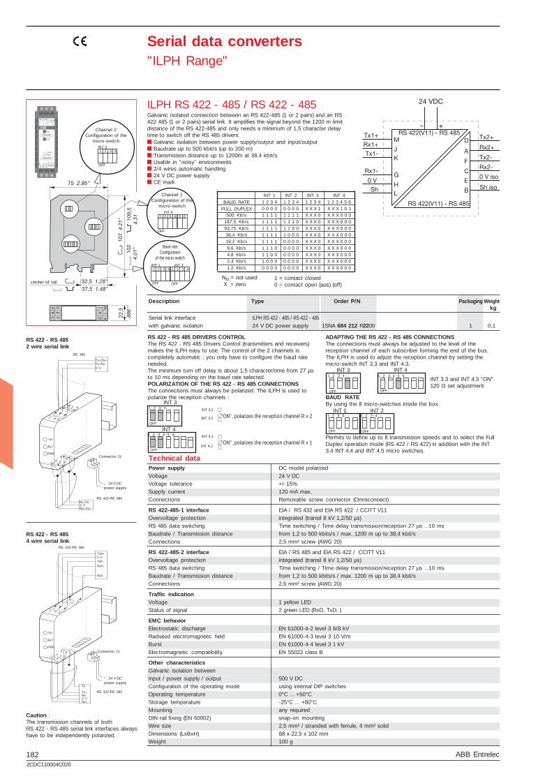
Serial data converters"ILPH Range"
ILPH RS 232 / RS 422 - 485RS 232 to RS 422-485 serial link without isolation
Economic version without isolation Baudrate up to 38,4 kbit/s Transmission distance up to 1200 m RS 485 1 or 2 pair handling Usable in "noisy" environments 24 V DC power supply CE mark
center of rail
Configuration ofthe jumper
Power supply polarizedVoltage 24 V DCVoltage tolerance 8,5...28 V DCSupply current 100 mA maxConnections removable screw connectors (AWG 20)
RS 232-1 serial link EIA RS 232 C / CCITT V24 V28Overvoltage protection integrated (transil 8 kV 1,2/50 µs)Baud rate / Transmission distance max. 38,4 kbits/s / max. 1200 mConnections 2,5 mm² screw connectors (AWG 20)
RS 422-485-2 serial link EIA RS 485 and EIA RS 422 / CCITT V11Overvoltage protection integrated (transil 8 kV 1,2/50 µs)Baud rate / Transmission distance max. 38,4 kbits / max. 1200 mConnections 2,5 mm² screw connectors (AWG 20)
Traffic indicationVoltage 1 yellow LEDStatus of signal 2 green LED (RxD, TxD)
EMC behaviorElectrostatic discharge EN 61000-4-2 level 3 6/8 kVRadiated electromagnetic field EN 61000-4-3 level 310 V/mBurst EN 61000-4-4 level 3 1 kVElectromagnetic compatibility EN 55022 class B
Other characteristicsGalvanic isolation betweeninput / power supply / output noConfiguration of the operating mode using internal jumperOperating temperature 0°C ... +50°CStorage temperature -25°C ... +80°CMounting any requiredDIN rail fixing (EN 50002) snap-on mountingWire size 2,5 mm² / stranded with ferrule, 4 mm² solidDimensions (LxBxH) 88 x 22,5 x 102 mmWeight 100 g
*CAUTION :When the RTS Signal is not activated,M terminal (RxD ILPH) has to beconnected to L terminal (CTRL IN).
RS 422 - RS 485SERIAL LINK (2 wires)
Product RS 232
Connector J1
24 V DCpower supply
Product RS 422-RS 485
** CAUTION :To be connected to 2 wired RS 485 only(not possible for 4 wired RS 422).When the RTS Signal is not activated, Mterminal (RxD ILPH) has to be connected toL terminal (CTRL IN).
RS 422 - RS 485SERIAL LINK (4 wires)
Product RS 232
Connector J1
24 V DCpower supply
Product RS 422-RS 485
RS 485 LINK ON ONE PAIR
R ON/OFF Jumper R in position R ON/OFF
E ON/OFF Jumper E in position E ON/OFF
The Receiver and the Transmitter are activated alternately (neverat the same time) depending on the status of the CTRL IN signal.
CTRL IN STATUS ACTION ON RS 4850 logic (+3V ≤ U ≤ +25V) Transmitter active /
Receiver inactive1 logic (-25V ≤ U ≤ -3V) Transmitter inactive /
Receiver activeHigh impedance Transmitter inactive /
Receiver active
NOTE : For RS 232 products running the RTS ( REQUEST TO SEND) signal, connectRTS to CTRL IN.Otherwise, connect M (RxD ILPH) to L (CTRL IN).
RS 485 LINK ON 2 PAIRS
R ON Jumper R in position R ON
E ON/OFF Jumper E in position E ON/OFF
Receiver permanently activeTransmitter controlled by the signal CTRL IN (see table for Transmitter operation asa function of CTRL IN)
RS 422 LINK ON TWO PAIRS
R ON Jumper R in position R ON
E ON Jumper E in position E ON
The Transmitter and Receiver are both permanently active.
POLARIZATION OF THE RS 422 - RS 485 LINE
The line must always be polarized. The ILPH is used to polarize the receptionchannel :Connection by 1 wire P+ (J1.1) with 5V (J1.4)Connection by 1 wire P- (J1.2) with 0V (J1.3)
ADAPTING THE RS 422 - RS 485 LINE
The line must always be adapted to the level of the reception channel of eachsubscriber forming the end of the bus. The ILPH is used to adapt the receptionchannel by setting the jumper Rt correctly :
* Line adaptation, Rt = 120 Ω ( general case )
* Line adaptation, Rt = 220 Ω
* No line adaptation, Rt = ∝
Serial link interfacewithout galvanic isolation
Description Type Order P/N Packaging Weightkg
Technical data
1SNA 684 231 R2500

179ABB Entrelec2CDC110004C0202
ILPH RS 232 / RS 422-485 1 0,1
R
Rt
E
R
E
R
E
R
E
Rt
Rt
Rt
ILPH RS 232 / RS 422 - 485
Serial data converters"ILPH Range"
Galvanic isolated converter for RS 232 to RS 422-485 serial links. Galvanic isolation between input/output and output/power supply Baudrate up to 38,4 kbit/s Transmission distance up to 1200 m RS 485 1 or 2 pair handling Usable in "noisy" environments 24 V DC power supply CE mark
** CAUTION :Only to be connected for RS 485 two pairs (ofno use for RS 422 two pairs). If the RTS signalis not generated, connect M (RxD ILPH)to L (CTRL IN).
* CAUTION :If the RTS signal is not generated,connect M (RxD ILPH) to L (CTRL IN).
RS 422 - RS 4852 WIRE SERIAL LINKS
RS 422 - RS 4854 WIRE SERIAL LINKS
Connector J1
24 V DCpower supply
RS 422-RS 485product
RS 232 product
Connector J1
24 V DCpower supply
RS 422-RS 485product
RS 232 product
Serial link interfacewith galvanic isolation
Configuration ofthe jumpers
center of railRS 422 LINK ON TWO PAIRS
R ON Jumper R in position R ON
E ON Jumper E in position E ON
The Transmitter and Receiver are both permanently active.
POLARIZATION OF THE RS 422 - RS 485 LINEThe line must always be polarized. The ILPH is used to polarizethe reception channel :Connection by 1 wire P+ (J1.1) with 5V (J1.4)Connection by 1 wire P- (J1.2) with 0V (J1.3)
ADAPTING THE RS 422 - RS 485 LINEThe line must always be adapted to the level of the receptionchannel of each subscriber forming the end of the bus.The ILPH is used to adapt the reception channel by setting thejumper Rt correctly :
* Line adaptation, Rt = 120 Ω ( general case )
* Line adaptation, Rt = 220 Ω
* No line adaptation, Rt = ∝
RS 485 LINK ON ONE PAIR
R ON/OFF Jumper R in position R ON/OFF
E ON/OFF Jumper E in position E ON/OFF
The Receiver and the Transmitter are activated alternately (neverat the same time) depending on the status of the CTRL IN signal.
CTRL IN STATUS ACTION ON RS 485
0 logic (+3V ≤ U ≤ +25V) Transmitter active /Receiver inactive
1 logic (-25V ≤ U ≤ -3V) Transmitter inactive /Receiver active
High impedance Transmitter inactive /Receiver active
CAUTION : For RS 232 products running the RTS ( REQUEST TOSEND) signal, connect RTS to CTRL IN. Otherwise, connect M(RxD ILPH) to L (CTRL IN).
RS 485 LINK ON 2 PAIRS
R ON Jumper R in position R ON
E ON/OFF Jumper E in position E ON/OFF
Receiver permanently activeTransmitter controlled by the signal CTRL IN ( see table forTransmitter operation as a function of CTRL IN )
Technical dataPower supply polarizedVoltage 24 V DCVoltage tolerance 8,5...28 V DCSupply current 100 mA maxConnections Removable screw connectors (Omniconnect)
RS 232-1 serial link EIA RS 232 C / CCITT V24 V28Overvoltage protection integrated (transil 8 kV 1,2/50µs)Baud rate / Transmission distance max. 38,4 kbits/s / max. 15 mConnections 2,5 mm² screw connectors (AWG 20)
RS 422-RS485-2 serial link EIA RS 485 and EIA RS 422 / CCITT V11Overvoltage protection integrated (transil 8 kV 1,2/50 µs)Baud rate / Transmission distance max. 38,4 kbits / max. 1200 mConnections 2,5 mm² screw connectors (AWG 20)
Traffic indicationVoltage 1 yellow LEDStatus of signal 3 green LED (RxD, TxD and CTRL-IN)
EMC behaviorElectrostatic discharge EN 61000-4-2 level 3 6/8 kVRadiated electromagnetic field EN 61000-4-3 level 310 V/mBurst EN 61000-4-4 level 3 1 kVElectromagnetic compatibility EN 55022 class B
Other characteristicsGalvanic isolation betweenRS 232/RS 422-485 and RS 422-485/power supply 500 V DCConfiguration of the operating mode using internal jumperOperating temperature 0°C ... +50°CStorage temperature -25°C ... +80°CMounting any requiredDIN rail fixing (EN 50002) snap-on mountingWire size 2,5 mm² / stranded with ferrule, 4 mm² solidDimensions (LxBxH) 88 x 22,5 x 102 mmWeight 100 g
Description Type Order P/N Packaging Weightkg
1SNA 684 233 R2700

180 ABB Entrelec2CDC110004C020
ILPH RS 232 / RS 422-4851 0,11 0,1
ILPH RS 232 / RS 422 - 485
Serial data converters"ILPH Range"
RS 422 - RS 4852 WIRE SERIAL LINK
3 way galvanic isolated converter for RS 232 to RS 422-485 serial links. 3 way galvanic isolation between power supply and input/output RS 485 switch on 2 or 4 wires Baudrate up to 38,4 kbit/s Transmission distance up to 1200 m RS 485 1 or 2 pair handling Usable in "noisy" environments 24...48 V DC and 115...230 V AC power supply CE marking
**CAUTION :Only to be connected for RS 485 twopairs (of no use for RS 422 two pairs).If the RTS signal is not generated, setSW2-1 in position ON.
*CAUTION :When the RTS signal is not generated, setSW2-1 in position ON.
RS 422 - RS 4854 WIRE SERIAL LINKS
Connector J1
Powersupply
Product RS 232
Connector J1
Powersupply
ProductRS 422 - RS 485
Product RS 232
ProductRS 422 - RS 485
Power supply Polarization for DC modelVoltage 24...48 V DC 115...230 V AC (50/60 Hz)Voltage tolerance -15% ... +20% -15% ... +15%Supply current 24 V DC<110 mA, 48 V DC<55 mA,115 V AC<40 mA, 230 V DC<26 mASupply power ~ 3 W ~ 3 VAConnections Removable screw connector (Omniconnect)
RS 232-1 serial link EA / TIA RS 232 new revision / CCITT V24 V28Overvoltage protection integrated (transil 8 kV 1,2/50 µs)Baud rate / Transmission distance max. 38,4 kbits/s / max. 15 m / 2500 pFConnections 2,5 mm² screw (AWG 20)
RS 422/485-2 serial link EIA RS 485 and EIA RS 422 CCITT V11Overvoltage protection integrated (transil 8 kV 1,2/50 µs)Baud rate / Transmission distance max. 38,4 kbits / max. 1200 mConnections 2,5 mm² screw (AWG 20)
Traffic indicationVoltage 1 yellow LEDStatus of signal 3 green LED (RxD, TxD and CTRL-IN)
EMC behaviorElectrostatic discharge EN 61000-4-2 level 3 6/8 kVRadiated electromagnetic field EN 61000-4-3 level 310 V/mBurst EN 61000-4-4 level 3 1 kVElectromagnetic compatibility EN 55022 class B
Other characteristicsGalvanic isolation betweenRS 232 / Power supply / RS 422-RS 485 1,5 kVConfiguration of the operating mode using internal jumperOperating temperature 0°C ... +50°CStorage temperature -25°C ... +80°CMounting any requiredDIN rail fixing (EN 50002) snap-on mountingWire size 2,5 mm² / stranded with ferrule, 4 mm² solidDimensions (LxBxH) 88 x 22,5 x 102 mmWeight 100 g
RS 485 LINK ON ONE PAIR
Set SW1-1, SW1-3, SW1-6, SW1-7 and SW1-8 to position ON. Thereceiver and the transmitter are activated alternately (never at thesame time), depending on the status of the CTRL IN signal.
CTRL IN STATUS Action on RS 485
0 Logic (3V ≤ U ≤ + 25V) Transmitter active /Receiver inactive
1 Logic (-25V ≤ U ≤ -3V) Transmitter inactive /Receiver active
High impedance Transmitter inactive /Receiver active
CAUTION : For RS 232 products running the RTS signal (REQUESTTO SEND), connect RTS to CTRL IN. Otherwise, set SW2-1 toposition ON.
RS 485 LINK ON TWO PAIRS
Set SW1-1, SW1-3, SW1-7 in position OFF.Set SW1-6, SW1-8 in position ON.The receiver is permanently active.The transmitter is controlled by the signal CTRL IN (see table fortransmitter operation as a fonction of CTRL IN).
RS 422 LINK ON TWO PAIRS
Set SW1-1, SW1-3, SW1-7 and SW1-8 in position OFF.Set SW1-6 in position ON.Transmitter and receiver are both permanently active.
POLARIZATION OF THE RS 422 - RS 485 LINE
The line must always be polarized.The ILPH is used to polarize the reception channel :Set SW1-4 and SW1-5 in position ON.
ADAPTING THE RS 422 - RS 485 LINE
The line must always be adapted to the level of the receptionchannel of each subscriber forming the end of the bus.
The ILPH is used to adapt the reception channel by setting thejumper SW1-2 correctly :
SW1-2 in position ON ⇒ line adaptation, Rt = 120 Ω(standard)SW1-2 in position OFF ⇒ no line adaptation, Rt = ∝
center of rail
Configurationof the jumper
Serial link interface3 way galvanic isolation 24...48 V DC power supply
115...230 V AC power supply
Description Type Order P/N Packaging Weightkg
Technical data
1SNA 684 333 R23001SNA 684 334 R2400

181ABB Entrelec2CDC110004C0202
ILPH RS 232 / RS 2321 0,11 0,1
ILPH RS 232 / RS 232
Serial data converters"ILPH Range"
3 way galvanic isolator between RS 232 serial interface and anotherRS 232 serial interface.
Ensures triple insulation between the 2 serial interfaces andbetween each and power supplyBaudrate up to 19,2 kbit/s (up to 64 kbit/s depending on cable)Transmission distance up to 15 mCan be used in "noisy" environmentsPower supply from 24...48 V DC and 115...230 V ACCE marking
Power supply DC model polarizedVoltage 24...48 V DC 115...230 V AC (50/60Hz)Voltage tolerance -15%...+20% -15%...+15%Supply current 24 V DC<155 mA;48 V DC<77 mA;110 V AC<40 mA;230 V DC<26 mASupply power ~ 3,15 W ~ 3,15 VAConnections Removable screw connector (Omniconnect)
RS 232-1 interface EIA / TIA RS 232 new revision / CCITT V24 V28Overvoltage protection integrated (transil 8 kV 1,2/50 µs)Transmission capacity /Transmission distance max. 19,2 kbits/s / max. 15 m / 2500 pFConnections 2,5 mm² screw (AWG 20)
RS 232-2 interface EIA / TIA RS 232 new revision / CCITT V24 V28Overvoltage protection integrated (transil 8 kV 1,2/50µs)Transmission capacity /Transmission distance max. 19,2 kbits/s / max. 15 mConnections 2,5 mm² screw (AWG 20)
Traffic indicationVoltage 1 yellow LEDStatus of signal 4 green LED (RxD, RxC/D, TxD, TxC/D)
EMC behaviorElectrostatic discharge EN 61000-4-2 level 3 6/8 kVRadiated electromagnetic field EN 61000-4-3 level 3 10 V/mBurst EN 61000-4-4 level 3 1 kVElectromagnetic compatibility EN 55022 class B
Other characteristicsGalvanic isolation betweeninput / power supply / output 1,5 kVConfiguration of the operating mode NoOperating temperature 0°C ... +50°CStorage temperature -25°C ... +80°CMounting any requiredDIN rail fixing (EN 50002) snap-on mountingWire size 2,5 mm² / stranded with ferrule, 4 mm² solidDimensions (LxBxH) 88 x 22,5 x 102 mmWeight 100 g
Connectionnot advisedaccording toEIA/TIA 232E
standard
or
Connectionnot advisedaccording toEIA/TIA 232E
standard
(to be connected)
Terminal equipment for ETTD(DTE) data processing
Data transmissionend equipment
ETCD (DCE)
center of rail
Serial link interface3 way galvanic isolation 24...48 V DC power supply
115...230 V DC power supply
Description Type Order P/N Packaging Weightkg
Technical data
1SNA 684 234 R20001SNA 684 244 R0200
182 ABB Entrelec2CDC110004C020
ILPH RS 422 - 485 / RS 422 - 4851 0,1
OFF
1 2 3 4
1 2 3 4 5 6
OFF
INT 3
INT 4
INT 3.1
INT 3.2
INT 4.1
INT 4.2
OFFOFF
INT 31 2 3 4 5 6
INT 41 2 3 4
OFF
1 2 3 4
OFF
1 2 3 4INT 1 INT 2
OFF
INT 11 2 3 4 1 2 3 4
INT 2
OFF
OFF
INT 41 2 3 4 5 6
OFF
INT 31 2 3 4
500 Kb/s187,5 Kb/s93,75 Kb/s38,4 Kb/s19,2 Kb/s9,6 Kb/s4,8 Kb/s2,4 Kb/s1,2 Kb/s
INT 11 2 3 40 0 0 01 1 1 11 1 1 11 1 1 11 1 1 11 1 1 11 1 1 01 1 0 01 0 0 00 0 0 0
INT 21 2 3 40 0 0 01 1 1 11 1 1 01 1 0 01 0 0 00 0 0 00 0 0 00 0 0 00 0 0 00 0 0 0
INT 31 2 3 4X X X 1X X X 0X X X 0X X X 0X X X 0X X X 0X X X 0X X X 0X X X 0X X X 0
INT 41 2 3 4 5 6X X X 1 0 1X X X 0 0 0X X X 0 0 0X X X 0 0 0X X X 0 0 0X X X 0 0 0X X X 0 0 0X X X 0 0 0X X X 0 0 0X X X 0 0 0
ILPH RS 422 - 485 / RS 422 - 485
Serial data converters"ILPH Range"
Galvanic isolated connection between an RS 422-485 (1 or 2 pairs) and an RS422 485 (1 or 2 pairs) serial link. It amplifies the signal beyond the 1200 m limitdistance of the RS 422-485 and only needs a minimum of 1,5 character delaytime to switch off the RS 485 drivers.
Galvanic isolation between power supply/output and input/outputBaudrate up to 500 kbit/s (up to 200 m)Transmission distance up to 1200m at 38,4 kbit/sUsable in "noisy" environments2/4 wires automatic handling24 V DC power supplyCE mark
Power supply DC model polarizedVoltage 24 V DCVoltage tolerance +/-15%Supply current 120 mA max.Connections Removable screw connector (Omniconnect)
RS 422-485-1 interface EIA / RS 432 and EIA RS 422 / CCITT V11Overvoltage protection integrated (transil 8 kV 1,2/50 µs)RS 485 data switching Time switching / Time delay transmission/reception 27 µs ...10 msBaudrate / Transmission distance from 1,2 to 500 kbits/s / max. 1200 m up to 38,4 kbit/sConnections 2,5 mm² screw (AWG 20)
RS 422-485-2 interface EIA / RS 485 and EIA RS 422 / CCITT V11Overvoltage protection integrated (transil 8 kV 1,2/50 µs)RS 485 data switching Time switching / Time delay transmission/reception 27 µs ...10 msBaudrate / Transmission distance from 1,2 to 500 kbits/s / max. 1200 m up to 38,4 kbit/sConnections 2,5 mm² screw (AWG 20)
Traffic indicationVoltage 1 yellow LEDStatus of signal 2 green LED (RxD, TxD, )
EMC behaviorElectrostatic discharge EN 61000-4-2 level 3 6/8 kVRadiated electromagnetic field EN 61000-4-3 level 3 10 V/mBurst EN 61000-4-4 level 3 1 kVElectromagnetic compatibility EN 55022 class B
Other characteristicsGalvanic isolation betweeninput / power supply / output 500 V DCConfiguration of the operating mode using internal DIP switchesOperating temperature 0°C ... +50°CStorage temperature -25°C ... +80°CMounting any requiredDIN rail fixing (EN 50002) snap-on mountingWire size 2,5 mm² / stranded with ferrule, 4 mm² solidDimensions (LxBxH) 88 x 22,5 x 102 mmWeight 100 g
Caution :The transmission channels of bothRS 422 - RS 485 serial link interfaces alwayshave to be independently polarized.
RS 422 - RS 4854 wire serial link
RS 422 - RS 4852 wire serial link
24 V DCpower supply
Connector J1
24 V DCpower supply
Connector J1
"ON", polarizes the reception channel R x 2
"ON", polarizes the reception channel R x 1
RS 422 - RS 485 DRIVERS CONTROLThe RS 422 - RS 485 Drivers Control (transmitters and receivers)makes the ILPH easy to use. The control of the 2 channels iscompletely automatic ; you only have to configure the baud rateneeded.The minimum turn off delay is about 1,5 character/time from 27 µsto 10 ms depending on the baud rate selected.POLARIZATION OF THE RS 422 - RS 485 CONNECTIONSThe connections must always be polarized. The ILPH is used topolarize the reception channels :
ADAPTING THE RS 422 - RS 485 CONNECTIONSThe connections must always be adjusted to the level of thereception channel of each subscriber forming the end of the bus.The ILPH is used to adjust the reception channel by setting themicro-switch INT 3.3 and INT 4.3.
BAUD RATEBy using the 8 micro-switches inside the box.
Permits to define up to 8 transmission speeds and to select the FullDuplex operation mode (RS 422 / RS 422) in addition with the INT3.4 INT 4.4 and INT 4.5 micro switches.
INT 3.3 and INT 4.3 "ON"120 Ω set adjustment
Nu = not used X = zerocenter of rail
Channel 1Configuration of the
micro-switch
Channel 2Configuration of the
micro-switch
Baud rateConfiguration
of the micro-switch
1 = contact closed0 = contact open (aus) (off)
BAUD RATEFULL DUPLEX
Serial link interfacewith galvanic isolation 24 V DC power supply
Description Type Order P/N Packaging Weightkg
Technical data
1SNA 684 212 R2200

183ABB Entrelec2CDC110004C0202
ILPH RS 232 / FO-S1 0,151 0,15
ILPH RS 232 / FO-P1 0,151 0,15
RS 232 / FO
RxDOV
TxD
OV
←→
~+
~-
(L)
(K)(M)
(J H G)
(E)
(F)(D)
(B)
(C)
(A)
ILPH RS 232 / FO
Serial data converters"ILPH Range"
3 way galvanic isolated Converter for RS 232 to optical fiber serial linkglass (S) or plastic (P).
3 way galvanic isolation between power supply and input/outputBaud rate up to 115,2 kbit/sAvailable for glass or plastic fiberTransmission distance up to 4 kmUsable in "very noisy" environments20...42 V AC/DC and 110...240 V AC/DC power supplyCE marked
Power suppliesSupply voltage 24...42 V AC/DC (50/60 Hz) 110...240 V AC/DC (50/60 Hz)Voltage tolerance -15% ... +10% -15% ... +10%Connections Omniconnect pluggable connector
RS 232 Interface 1 CCITT V.24/DIN 66020- CCITT V.28 DIN 66259-EIA 232 EProtection Integrated (transil 8 kV 1.2/50µs)Max. speed /Max. distance Max. 115.2 kbits/s / max. 15 m / 2500 pFConnections Omniconnect pluggable connector
Fiber optic interface 2 DIN VDE 0888-1Type of fiber / Connections Multimode fiber
Glass : ST connectorPlastic : FSMA screw connector
Wavelength Glass : 820 nmPlastic : 655 nm
Max. transmission power Glass : 50/125 µm : -14.4 db/mGlass : 62.5/125 µm : -14 db/mPlastic : 980/1000 µm : -8 db/m
Max. reception power Glass : -28 db/mPlastic : -20 db/m
Max. speed Max. 115.2 kbits/sMax. distance Glass : 50/125 µm : 3 km
Glass : 62.5/125 µm : 4 kmPlastic : 980/1000 µm : 40 m
Status indicationPower supply / Data exchange 1 green LED / 2 green LEDs (RxD, TxD)
EMC behaviorElectrostatic discharge EN 61000-4-2 Level 3 6/8 kVRadiated electromagnetic field EN 61000-4-3 Level 3 10 V/mBurst EN 61000-4-4 Level 3 1 kVElectromagnetic compatibility EN 55022 Class B
Other characteristicsGalvanic isolation input /power supply / output 2.5 kVOperating temperature -20°C ... +60°CStorage temperature -40°C ... +85°CMounting Onto DIN Rail (EN 50002)Connections 14 AWG (2.5 mm²) fine stranded / 12 AWG (4 mm²) rigidDimensions (LxWxH) 105 x 22.5 x 112 mm / 4.13 x 0.89 x 4.41"Weight 150 g / 0.33 lb
Technical data
Shielding
FOSending
FOReceiving
Shielding
Serial link interface3 way galvanic isolation 24...42 V AC/DC Power supply
110...240 V AC/DC Power supply
Serial link interface3 way galvanic isolation 24...42 V AC/DC Power supply
110...240 V AC/DC Power supply
U : power supply
FO sending
FO receiving
Pluggableomniconnectterminals
Approvals : in process
Description Type Order P/N Packaging Weightkg
1SNA 684 236 R22001SNA 684 237 R2300
1SNA 684 238 R04001SNA 684 239 R0500

184 ABB Entrelec2CDC110004C020
ILPH RS 485 / FO-S1 0,151 0,15
ILPH RS 485 / FO-P1 0,151 0,15
OFF
1 2 3 4 5 6 7 8SW 1
OFF
SW 21 2 3 4 5 6
ILPH RS 485 / FO
RS 485 / FO
←
OVD - D +
OV
←
~-
~+
onoff
Serial data converters"ILPH Range"
3 way galvanic isolated converter for RS 485 (1 pair) to optical fiberserial link glass (S) or plastic (P).
3 way galvanic isolation between power supply and input/outputBaud rate up to 1.5 Mbit/sAvailable for glass fiber or plastic fiberTransmission distance up to 4 kmUsable in "very noisy" environments20...42 V AC/DC and 110...240 V AC/DC power supplyCE marked
Baud rate :SW1 DIP switch configuration
Legend
Approvals : in process
End-of-line resistor, polarizationSW2 DIP switch configuration
Baudrate bit/s
U : power supply
Pluggableomniconnectterminals
FO sending
FO receiving
PolarizationConfiguration of the
micro-switch
Baud rateConfiguration of the
micro-switch
Power suppliesSupply voltage 24...42 V AC/DC (50/60 Hz) 110...240 V AC/DC (50/60 Hz)Voltage tolerance -15% ... +10% -15% ... +10%Connections Omniconnect pluggable connector
RS 485 interface 1 ISO / IEC 8482 / DIN 66 259-4; EIA 485Protection Integrated (8 kV 1.2/50µs)Max. speed / max. distance Max. 1.5 Mbits/s / max. 1200 m (38.4 kbit/s)Connections Omniconnect Pluggable connector
Optic fiber interface 2 DIN VDE 0888-1Type of fiber / Connections Multimode fiber
Glass : ST connectorPlastic : FSMA screw connector
Wavelength Glass : 820 nmPlastic : 655 nm
Max. transmission power Glass : 50/125 µm : -14.4 db/mGlass : 62.5/125 µm : -14 db/mPlastic 980/1000 µm : -8 db/m
Max. reception power Glass : -28 db/mPlastic : -20 db/m
Max. speed Max. 1.5 Mbit/sMax. distance Glass : 50/125 µm : 3 km
Glass : 62.5/125 µm : 4 kmPlastic 980/1000 µm : 40 m
Status indicationPower supply / Data exchange 1 green LED / 2 green LEDs (RxD, TxD)
EMC behaviorElectrostatic discharge EN 61000-4-2 Level 3 6/8 kVRadiated electromagnetic field EN 61000-4-3 Level 3 10 V/mBurst EN 61000-4-4 Level 3 1 kVElectromagnetic compatibility EN 55022 Class B
Other characteristicsGalvanic isolation input /power supply / output 2.5 kVFunction configuration With DIP-SwitchesOperating temperature -20°C ... +60°CStorage temperature -40°C ... +85°CMounting Onto DIN RailConnections 14 AWG (2,5mm²) / fine stranded, 12 AWG (4 mm²) rigidDimensions (LxWxH) 105 x 22.5 x 112 mm / 4.13 x 0.89 x 4.41"Weight 150 g / 0.33lb
Technical data
Description Type Order P/N Packaging Weightkg
Serial link interface3 way galvanic isolation 24...42V AC/DC Power supply
110...240 V AC/DC Power supply
Serial link interface3 way galvanic isolation 24...42V AC/DC Power supply
110...240 V AC/DC Power supply
Shielding
FOSending
FOReceiving
Shielding
1SNA 684 246 R04001SNA 684 247 R0500
1SNA 684 248 R16001SNA 684 249 R1700

185ABB Entrelec2CDC110004C0202
ILPH BdC / RS 422 - 4851 0,1
INT4INT4INT4INT4INT4
RRRRR
EEEEE
INT2INT2INT2INT2INT2
INT3INT3INT3INT3INT3
RRRRR
EEEEE
INT2 R ONINT2 R ONINT2 R ONINT2 R ONINT2 R ONINT3 EINT3 EINT3 EINT3 EINT3 EON / OFFON / OFFON / OFFON / OFFON / OFF
RRRRR
EEEEE
INT2 R ONINT2 R ONINT2 R ONINT2 R ONINT2 R ON
INT3 E ONINT3 E ONINT3 E ONINT3 E ONINT3 E ON
RtRtRtRtRt
RtRtRtRtRt INT1INT1INT1INT1INT1
INT1INT1INT1INT1INT1
S1 S2 S3 S4S1 S2 S3 S4S1 S2 S3 S4S1 S2 S3 S4S1 S2 S3 S4ONONONONON
OFFOFFOFFOFFOFF
INT4INT4INT4INT4INT4
INT1INT1INT1INT1INT1 INT2INT2INT2INT2INT2 INT3INT3INT3INT3INT3
RtRtRtRtRt EEEEE RRRRR
S1S1S1S1S1 S2S2S2S2S2 S3S3S3S3S3 S4S4S4S4S4
INT4INT4INT4INT4INT4
LINE AMPLIFIER CONFIGURATIONConfiguration of amplifiers of the RS 422 - RS 485 (Receiver,Transmitter) line provides greater flexibility of use.The various configurations can be selected using the 2 jumpers(R INT2, E INT1) located inside the box.
RS 485 LINK ON ONE PAIR
The Receiver and the Transmitter are activated alternately (never atthe same time) depending on the status of the Current LoopReception signal.
RS 485 LINK ON TWO PAIRS
Receiver permanently active. Transmitter controlled by the CurrentLoop Reception signal.
RS 422 LINK ON TWO PAIRS
The Receiver and the Transmitter are both permanently active.
Serial data converters"ILPH Range"
Configuration ofthe jumper
Configurationof the micro-switches
Polarization
center of rail
Galvanic isolated converter for current loop to RS 422-485 (1 or 2pairs) serial link.
Galvanic isolation between power supply/current loopand RS 422-485/current loopActive/passive 0...20 mA / 4...20 mA selectablePositive or negative logic selectableBaudrate up to 38,4 kbit/s (up to 2400 m)Transmission distance up to 2400 m (1200 m RS 485 and1200 m current loop)Usable in "noisy" environments24 V DC power supplyCE marking
Serial link interfacewith galvanic isolation 24 V DC power supply
Technical data
RS 422 - RS 4852 wire serial link
CONNECTIONSExample of connection with a CL (currentLoop) product, Transmission (TxD) in activemode and Reception (RxD) in passive mode.Then, the ILPH must be configured andconnected Reception (RxD) in passive modeand Transmission (TxD) in active mode.Note : For any other configuration, seeschematic diagram or front sticker of theproduct.
Note :The TxD channel of the RS 422 - RS 485 linkmust be polarized independently too.
RS 422 - RS 4854 wire serial link
Current LoopCurrent LoopCurrent LoopCurrent LoopCurrent Loop
Connector J1Connector J1Connector J1Connector J1Connector J1
24 V DC24 V DC24 V DC24 V DC24 V DCpower supplypower supplypower supplypower supplypower supply
Current LoopCurrent LoopCurrent LoopCurrent LoopCurrent Loop
Connector J1Connector J1Connector J1Connector J1Connector J1
24 V DC24 V DC24 V DC24 V DC24 V DCpower supplypower supplypower supplypower supplypower supply
Protection ON Protection OFF, used if power supply atminimum value (21,6 V).
Power supply DC model polarizedVoltage 24 V DCVoltage tolerance +/-10%Supply current 120 mA max.Connections Removable screw connector (Omniconnect)
CL interface (Current Loop 1) active/passive 0...20 mA / 4...20 mA, mode is settableLogic level 0 = 20 mA or 1 = 20 mA, settableBaud rate / Transmission distance max. 38,4 kbit/s / max. 1200 mConnections 2,5 mm² screw (AWG 20)
RS 422/485-2 serial link EIA RS 485 and EIA RS 422 / CCITT V 11Overvoltage protection integrated (transil 8 kV 1,2/50 µs)Baud rate / Transmission distance max. 38,4 kbit/s / max. 1200 mConnections 2,5 mm² screw (AWG 20)
Traffic indicationVoltage 1 yellow LEDStatus of signal 2 green LED (RxD, TxD)
EMC behaviorElectrostatic discharge EN 61000-4-2 level 3 6/8 kVRadiated electromagnetic field EN 61000-4-3 level 3 10 V/mBurst EN 61000-4-4 level 3 1 kVElectromagnetic compatibility EN 55022 class B
Other characteristicsGalvanic isolation between depending on Current Loop (active/passive)input /output and power supply / output 500 V DC (active) / 2000 V DC (passive)RS 422-485 power supply 500 V DCConfiguration of the operating mode using internal DIP switchesOperating temperature 0°C ... +50°CStorage temperature -25°C ... +80°CMounting any requiredDIN rail fixing (EN 50002) snap-on mountingWire size 2,5 mm² / stranded with ferrule, 4 mm² solidDimensions (LxBxH) 88 x 22,5 x 102 mmWeight 100 g
E ON/OFF Jumper E in position E ON/OFFR ON/OFF Jumper R in position R ON/OFF
R ON Jumper R in position R ONE ON/OFF Jumper E in position E ON/OFF
R ON Jumper R in position R ONE ON Jumper E in position E ON
POLARIZATION OF THE RS 422 - RS 485 LINEThe line must always be polarized. The ILPH is used to polarizethe reception channel :Connection by 1 wire P+ (J1.1) with 5 Viso (J1.4)Connection by 1 wire P- (J1.2) with 0 Viso (J1.3)
ADAPTING THE RS 422 - RS 485 LINEThe line must always be adapted to the level of the reception channel ofeach subscriber forming the end of the bus. The ILPH is used to adaptthe reception channel by setting the jumper Rt correctly :
POLARIZATIONThe polarization can be configured using the INT4 jumper.
* Line adaptation, Rt = 120 Ω (Standard)
* No line adaptation, Rt = ∞
Transmission (TxD) activeTransmission(TxD) passiveReception (RxD) activeReception (RxD) passive4...20 mA Signal0...20 mA SignalSignal logic 1 = 20 mASignal logic 0 = 20 mA
LegendLegendLegendLegendLegendONONONONONOFFOFFOFFOFFOFF
Description Type Order P/N Packaging Weightkg
ILPH CL / RS 422 - 485
CL
1SNA 684 232 R2600

186 ABB Entrelec2CDC110004C020
ILPH RS 232 / BdC1 0,1
S1 S2 S3 S4
S1 S2 S3 S4ON
OFF
S1 S2 S3 S4ON
OFF
S1 S2 S3 S4ON
OFF
Serial data converters"ILPH Range"
Technical data
Galvanic isolated Converter for RS 232 to current loop serial link.
Galvanic isolation between power supply/current loopand RS 232/current loopActive/Passive 0...20 mA / 4...20 mA selectablePositive or negative logic selectableBaudrate up to 38,4 kbit/sTransmission distance up to 1200 mUsable in "noisy" environments24 V DC power supplyCE marking
Configuration ofthe micro-switches
center of rail
Serial link interfacewith galvanic isolation 24 V DC power supply
Power supply DC model polarizedVoltage 24 V DCVoltage tolerance +/-10%Supply current 120 mA max.Connections Removable screw connector (Omniconnect)
RS 232-1 serial link EIA RS 232 C / CCITT V 24 V 28Overvoltage protection integrated (transil 8 kV 1,2/50 µs)Baud rate / Transmission distance max. 38,4 kbit/s / max. 15 mConnections 2,5 mm² screw (AWG 20)
BdC serial link (current loop) 2 active/passive 0...20 mA / 4...20 mA mode settableLogic level 0=20 mA or 1=20 mA settableBaud rate / Transmission distance max. 38,4 kbit/s / max. 1200 mConnections 2,5 mm² screw (AWG 20)
Traffic indicationVoltage 1 yellow LEDStatus of signal 2 green LED (RxD, TxD)
EMC behaviorElectrostatic discharge EN 61000-4-2 level 3 6/8 kVRadiated electromagnetic field EN 61000-4-3 level 3 10 V/mBurst EN 61000-4-4 level 3 1 kVElectromagnetic compatibility EN 55022 class B
Other characteristicsGalvanic isolation between depending on current loop (active/passive)Current loop / RS 232 500 V DC (active) / 2000 V DC (passive)Current loop / power supply 500 V DC (active) / 2000 V DC (passive)Configuration of the operating mode using internal DIP switchesOperating temperature 0°C ... +50°CStorage temperature -25°C ... +80°CMounting any requiredDIN rail fixing (EN 50002) snap-on mountingWire size 2,5 mm² / stranded with ferrule, 4 mm² solidDimensions (LxBxH) 88 x 22,5 x 102 mmWeight 100 g
Current loop
24 V DCpower supply
CONNECTIONSExample of connection with a CL (Current Loop) product,Transmission (TxD) in active mode and Reception (RxD) in passivemode. Then, the ILPH must be configured and connectedReception (RxD) in passive mode and Transmission (TxD) in activemode.
CAUTION : For any other configuration, see schematic diagram orfront sticker of the product.
CONFIGURATIONThe various configurations can be selected using the 4 micro-switches located inside the box.
OPERATING MODE ACTIVE OR PASSIVEThe Current Loop's Transmission and Reception can beindependently in active or passive mode.Select operating mode using S1 and S2.
S1 Transmission(TxD) ON = Active / OFF = PassiveS2 Reception (RxD) ON = Active / OFF = Passive
SIGNAL LEVELSelect signal level 4-20 mA or 0-20 mA.This selection is made using micro-switch S3
S3 ON = 4-20 mA / OFF = 0-20 mA
Caution :It is not possible to select a 4-20 mA signal when theReception is in active mode.
LOGIC LEVEL
Configuration : Positive logic (0 Logic = 20 mA)or negative logic (1 Logic = 20 mA)
using micro-switch S4
S4 ON = (1 = 20 mA) / OFF = (0 = 20 mA)
Description Type Order P/N Packaging Weightkg
ILPH RS 232 / CL
CL
1SNA 684 202 R0100


![ABB Serial Data Converters[1]](https://img.dokumen.tips/doc/110x75/5525aded550346a26e8b4a20/abb-serial-data-converters1.jpg)


