Embed Size (px)
Citation preview
Tektronix, Inc.
Serial ATA
International Organization
Revision 1.4 Version 1.0 Aug 27th 2009
Serial ATA Interoperability Program Revision 1.4 Tektronix MOI for RSG tests using Tektronix AWG7000 series Arbitrary Waveform Generator.
This document is provided "AS IS" and without any warranty of any kind, including, without limitation, any express or implied warranty of non-infringement, merchantability or fitness for a particular purpose. In no event shall SATA-IO or any member of SATA-IO be liable for any direct, indirect, special, exemplary, punitive, or consequential damages, including, without limitation, lost profits, even if advised of the possibility of such damages. This material is provided for reference only. The Serial ATA International Organization does not endorse the vendor equipment outlined in this document.
1 Tektronix SATA-IO Rev 1.4 RSG MOI v1.0

Tektronix, Inc.
TABLE OF CONTENTS TABLE OF CONTENTS.........................................................................................2
MODIFICATION RECORD ..................................................................................3
INTRODUCTION....................................................................................................5
DETAILED TESTS..................................................................................................6 TEST RSG-01 - GEN1I (1.5GB/S)RECEIVER JITTER TEST ............................................................... TEST RSG-02 – GEN2I (3 GB/S) RECEIVER JITTER TEST................................................................ TEST RSG-03 – GEN3I (6 GB/S) RECEIVER JITTER TEST................................................................ TEST RSG-05 – ASYNCHRONOUS RECEIVER STRESS TEST ............................................................ TEST RSG-06 – ASYNCHRONOUS RECEIVER STRESS TEST WITH SSC ...........................................
APPENDIX A – RESOURCE REQUIREMENTS ...............................................9APPENDIX B – TEST SETUPS...........................................................................11
DRIVE RECEIVER TESTS USING BIST-FIS ....................................................................................... HOST RECEIVER TESTS USING BIST-FIS.........................................................................................
APPENDIX C – MEASUREMENT CALIBRATION .......................................12APPENDIX D – AWG-7000 SETUPS ..................................................................19APPENDIX E – FRAME ERROR DETECTOR................................................21APPENDIX F – J9005A EXTERNAL Rj SOURCE ……………….…………26APPENDIX G – ARBITRARY WAVEFORM GENERATOR ACCURACY..27
2 Tektronix SATA-IO Rev 1.4 RSG MOI v1.0

Tektronix, Inc.
MODIFICATION RECORD
September 6, 2006 (Version 0.7) INITIAL RELEASE Mike Martin, John Calvin: RSG MOI contributions
July 12, 2007 (Version 1.0RC) released for general membership review. September 26, 2007 (Version 1.0) Revised after 90 day general membership review, and submitted for inclusion with the SATA 1.2 IW test program.
Chris Skach Dec 19, 2007 (R13_v0_09,Version 0.9) Revised after IW4 plugfest , and submitted for inclusion with the SATA 1.3 IW test program.
Chris Skach Aug 25th 2008 (R14_v0_09,Version 0.5) Revised to include SATA 6Gb/s Preliminary Test procedure and Jitter Calibration
Chris Skach
March 164th 2009 (R14_v0_095,Version 0.81) UTD1.4 Preliminary Test procedure and Jitter Calibration Chris Skach
March 27th 2009 (R14_v0_0.90) Tektronix RSG MOI finalized Chris Skach
April 21st 2009 (R14_v0_0.91) Tektronix RSG MOI updated to include UTD 1.4 changes Chris Skach
May 15th 2009 (R14_v0_0.92) Removed requirement for PLL clock recovery setting in amplitude measurement Chris Skach
May 19th 2009 (R14_v0_0.93) Edited RSG jitter tables to reflect UTD updates. Added Analog/vs Re-timed loopback check
Chris Skach May 26th 2009 (R14_v0_0.93) Edited RSG-05,06 test tables to reflect UTD updates. Added text regarding Rj note both prompted by Bent Hessen-Schmidt
Chris Skach May 28th 2009 (R14_v0_1.0RC) Moved to 1.0RC status
Chris Skach Aug 27th 2009 (R14_v0_1.0) Moved to 1.0 status
Chris Skach
3 Tektronix SATA-IO Rev 1.4 RSG MOI v1.0

Tektronix, Inc.
ACKNOWLEDGMENTS The SATA-IO would like to acknowledge the efforts of the following individuals in the development of this test suite. Creation of this document Tektronix, Inc. John Calvin
Chris Skach Bill Leineweber Kalev Sepp
4 Tektronix SATA-IO Rev 1.4 RSG MOI v1.0

Tektronix, Inc.
INTRODUCTION The tests contained in this document are organized in order to simplify the identification of information related to a test, and to facilitate in the actual testing process. Tests are separated into groups, primarily in order to reduce setup time in the lab environment, however the different groups typically also tend to focus on specific aspects of device functionality. The test definitions themselves are intended to provide a high-level description of the motivation, resources, procedures, and methodologies specific to each test. Formally, each test description contains the following sections: Purpose
This document outlines precise and specific procedures required to conduct SATA IW 1.4 tests, as they pertain to receiver testing. This document covers the following tests which are all based around testing the receiver channel using a directly synthesized framed composite pattern with a precise level of digital impairment using an Arbitrary Waveform Generator. The actual framed Composite pattern utilized is a synthesized version of the pattern outlined in the SATA_Pretest_MOI.
5 Tektronix SATA-IO Rev 1.4 RSG MOI v1.0
Tektronix, Inc.
Detailed Tests Test RSG-01 – Gen1 (1.5Gb/s) Receiver Jitter Test This test requirement is applicable to all products. (Gen1i-Gen3i) Test RSG-02 – Gen2i (3Gb/s) Receiver Jitter Test This test requirement is applicable to all PUTs claiming ability to run Gen2i and Gen3i rates. Test RSG-03 – Gen3i (6Gb/s) Receiver Jitter Test (Informative) This test requirement is applicable to all PUTs claiming ability to run Gen3i rates. Test RSG-05 – Asynchronous Receiver Stress Test at + 350ppm (Informative) This test requirement is applicable to all PUTs. Test RSG-06 – Asynchronous Receiver Stress Test with SSC (Informative) This test requirement is applicable to all PUTs. Purpose: To verify that the Product Under Test (PUT) meets receiver tolerance specifications of section 7.4.11, and 7.4.12 of SerialATA Revision 3.0. References:
SerialATA Revision 3.0 SATA Interop_UnifiedTest_Rev1.4
The most current versions of above documents may be found at the Serial ATA document repository: http://www.serialata.org/developers/technical_library.asp Resource Requirements: See appendix A Signal Calibration: See appendix C.1 for Transition time validation Note: this step should precede the Jitter Calibration steps.
See appendix C.2 for Rj calibration See appendix C.3 for Tj calibration See appendix C.4 for Amplitude. Test Setup: Connect equipment as shown in Appendix B, figure 1 or 2 as appropriate. Use AWG Framed Long COMP Receiver Test Pattern library of stressed data patterns outlined in Appendix D for each RSG test required. This library includes all stressed patterns including RJ, Dj including CIC/ISI and with sine Pj source frequencies of:
5MHz 10MHz 33MHz *62MHz * Note for RSG-05 and RSG-06 only the 62MHz jitter profile is used for the test.
Test Procedure: This procedure should be applied to the worst case port (in a multi-port system/host) as determined through the worst case port identification MOI. If necessary, use ancillary equipment to place the SATA product-under-test (host or drive) in BIST-L mode .
6 Tektronix SATA-IO Rev 1.4 RSG MOI v1.0

Tektronix, Inc.
Note: In most cases the AWG will complete the entire process from OOB sequencing to BIST-L, and finally issuing a repeating Framed COMP pattern. In certain cases, it may be necessary to use ancillary equipment to properly initiate BIST-L modes of operation.. Once in BIST-L mode, use sequencer to run specific test waveform in test suite. To validate PUT is not in Analog Loopback mode. • Right mouse click on the 62Mhz (RSG01-c) waveform and select Force Jump Here. • Select Ch1 Output On and select Run • Verify the PUTs transmitted 62Mhz spectrum is suppressed by viewing the jitter spectral content using
DPOJET. • RSG01-03 is only Normative if the 62MHz spectral content is suppressed.
To validate that the frame error counting HW is functioning properly, recall the error injector (1 Frame Error) framed comp pattern. (SFCP_1ERR_Clean.wfm from the SATA-Gen1i-RSG-Compliance.awg setup ). Observe that the frame error counter increments by one every time the AWG Run button is pressed. Clear the error counters back to 0 once this has been validated. Recall the clean (no jitter) framed comp pattern (SFCP_2A_0ERR_clean.wfm from the SATA-GenX-RSG-Compliance.awg setup) and run to observe that no frame error count increments are occurring for 1 minute of initial operation. For each of the four sine jitter (PJ) frequencies defined, apply the appropriate Stressed Framed COMP patterns outlined in table below by selecting it in the sequence menu. Perform the Frame Error Count test for each frequency for a period of listed below . Record Frame Error Count for each jitter frequency. Test pattern setup file for RSG-01: Normative, Required for all PUTs. AWG7000 SATA- RSG-01_V1_4Compliance.zip
SATA usage model: 1.5Gbps(Gen1) + 0ppm
Test time/PJ freq waveform RSG01a 10Mhz 10 Min RSG01b 33Mhz 10 Min RSG01c 62Mhz 10 Min RSG01d 5Mhz 10 Min
Test pattern setup file for RSG-02: Normative, Required for PUTs claiming ability to run Gen2i and Gen3i rates. AWG7000 SATA- RSG-02_V1_4Compliance.zip
SATA usage model: 3Gbps(Gen2) + 0ppm
Test time/PJ freq waveform RSG02a 10Mhz 5 Min RSG02b 33Mhz 5 Min RSG02c 62Mhz 5Min RSG02d 5Mhz 5 Min
Test pattern setup file for RSG-03: Informative, Required for PUTs claiming ability to run Gen3i rates. AWG7000 SATA- RSG-03_V1_4Compliance.zip
SATA usage model: 6Gbps(Gen3i) +0ppm
Test time/PJ freq waveform RSG03a 10Mhz 2.5 Min RSG03b 33Mhz 2.5 Min RSG03c 62Mhz 2.5Min RSG03d 5Mhz 2.5 Min
Test pattern setup file for RSG-05: Normative, Required for all PUTs. AWG7000 SATA- RSG-05_V1_4Compliance.zip
SATA usage model: 1.5Gbps + 350ppm
Test time/PJ freq waveform >= 18 successive iterations of Frame COMP wfm. With 62MHz Pj component
Test pattern setup file for RSG06: Informative, Required for all PUTs. AWG7000 SATA- RSG-06_V1_4Compliance.zip
SATA usage model: 1.5Gbps - 350ppm with ideal 5000ppm triangular downspread SSC at 33KHz modulation freq.
Test time/PJ freq waveform >= 18 successive iterations of Frame COMP wfm. With 62MHz Pj component
7 Tektronix SATA-IO Rev 1.4 RSG MOI v1.0

Tektronix, Inc.
Data Rate Range is between 1.5 Gb/s – 5350ppm and 1.5 Gb/s -350ppm.
Observable Results:
Frame Error Counter must record 0 frame errors over a specified period at each of the prescribed jitter frequencies. Record the number of observed errors at each of the three phases of this test. In the case where at least 1000 errors are observed during test execution, the test iteration may stop and specific test would report a failure due to high number of errors.
Accuracy: Possible Problems: Possible Issues: While the Interop testing require the use of the Pretest_MOI_Framed_COMP if the device does not support the Pretest_MOI_Framed_COMP then the Pretest_MOI_Framed_COMP_with_4_ALIGNs version can be used with a waiver request or the COMP_Framed_RD- pattern, which also comply with the 256 word ALIGN spacing.
8 Tektronix SATA-IO Rev 1.4 RSG MOI v1.0

Tektronix, Inc.
Appendix A – Resource Requirements The resource requirements include two separate sets of equipment. The equipment required for PHY and TSG tests is shown in section A.1, and the equipment required for TX and RX tests is shown in section A.2, and the equipment required for OOB tests is shown in section A.3. A.1 Equipment for verifying Signal Source Calibration
1. Real-time Digital Oscilloscope DPO/DSA 71254KB series (or higher), DPO/DSA71254 (or higher)
2. Test Fixture Crescent Heart Software Fixture TF-SATA-NE-XP, TF-SATA-NE-ZP or equivalent.
3. Cables 179-4944-01 for valid results using the distributed AWG setup files
4. Software
Tektronix AWG7000 Framed Long COMP Receiver Test Pattern library Tektronix SDX100 opt ISI, opt SSC (Required only for waveform generation) Tektronix TDSDPOJET
A.2 Equipment for Performing SATA RSG Tests
1. Signal Generator AWG7102 or AWG7122B, option 6 (interleaved output with 20Gs/s or 24Gs/s sample rate) and opt 01 (64M memory) and opt 08 for AWG7122B (Fast Sequencing) AWG7122B recommended for Gen3i testing
2. Frame Error Counter CHS FEC for Gen1 and Gen2 Finisar Xgig for Gen1- Gen3i Xgig-C042 (qty 1): Four Slot Portable or Rack mountable Chassis Xgig-B860Sc: 6 Gb/s SAS/SATA Wide Port Blade with mini SAS connectors, 16 GB memory, w/ Link Extender (LE) Xgig-S86AS: Wide-Port 6Gb/s SAS/SATA Analyzer Function Key (8 ports / 4 links) Performance Monitor SW or SerialTek BusXpert Micro Analyzer Gen1- Gen3i MA-2x6SA-2GB BusXpert Micro Analyzer, 2-port, 6Gb/s SAS/SATA, 2.25GB Buffer, Advanced Triggering and Segmented Buffer BusXpert SW
3. Test Fixture Crescent Heart Software Fixture TF-SATA-NE-XP , TF-SATA-NE-ZP or equivalent Molex SAS test board 73931-2544 for Finisar FEC
4. Cables 179-4944-01 for valid results using the distributed AWG setup files.
5. Attenuators Two 6 dB (2:1) attenuators should inserted at the end of the cables from the AWG attaching to the inputs of the fixtures. Part number (Tek) 015-1001-01 are recommended.
9 Tektronix SATA-IO Rev 1.4 RSG MOI v1.0

Tektronix, Inc.
6. SATA BISTFIS initialization system Any system capable of controlling Gen1 and Gen2 products-under-test (PUT), and capable of placing the PUT into BIST-L mode. For host testing, this could be a system such as the Catalyst SATA analyzer and device emulator. For drive testing, this could be a system such as the Ulink DriveMaster running on a SATA capable host system. It is possible that the AWG7000 might be used to perform the BIST-L setup, as well as provide the stressed data pattern for receiver testing. It is also acceptable to utilize proprietary solutions to meet this requirement.
7. Software Tektronix AWG7000 RX SATA PHY 1.4 Test Pattern library available on www.tek.com
8. Optional Rj source NoiseCom J9005A
Appendix B – Test Setups Drive receiver tests using BIST-FIS Once the Device or Drive DUT has been put in BIST-L mode, the Framed Long COMP pattern is applied with the AWG7000, and the frame errors are counted using a Frame Error Counter using the following configuration:
Scope is only required for waveform validation and loopback verification
Ch1 Ch2
Tek DSA
Ch1+
Ch1 –
Tek AWG
DUT Rx+
Rx-
Tx+
Tx-
Rx+
Rx-
SMA
SMA
SMA
Silicon
Power Divider
SMA Cable
DPOJET
AWG7122 opt06, opt 08
LAN/USB
FEC
SMA Test Fixture
SMA Test Fixture
SATA I,II, III- Finisar, SerialTek SATA I, II CHS
Figure 1: Test the receiver using BIST-L
10 Tektronix SATA-IO Rev 1.4 RSG MOI v1.0
Tektronix, Inc.
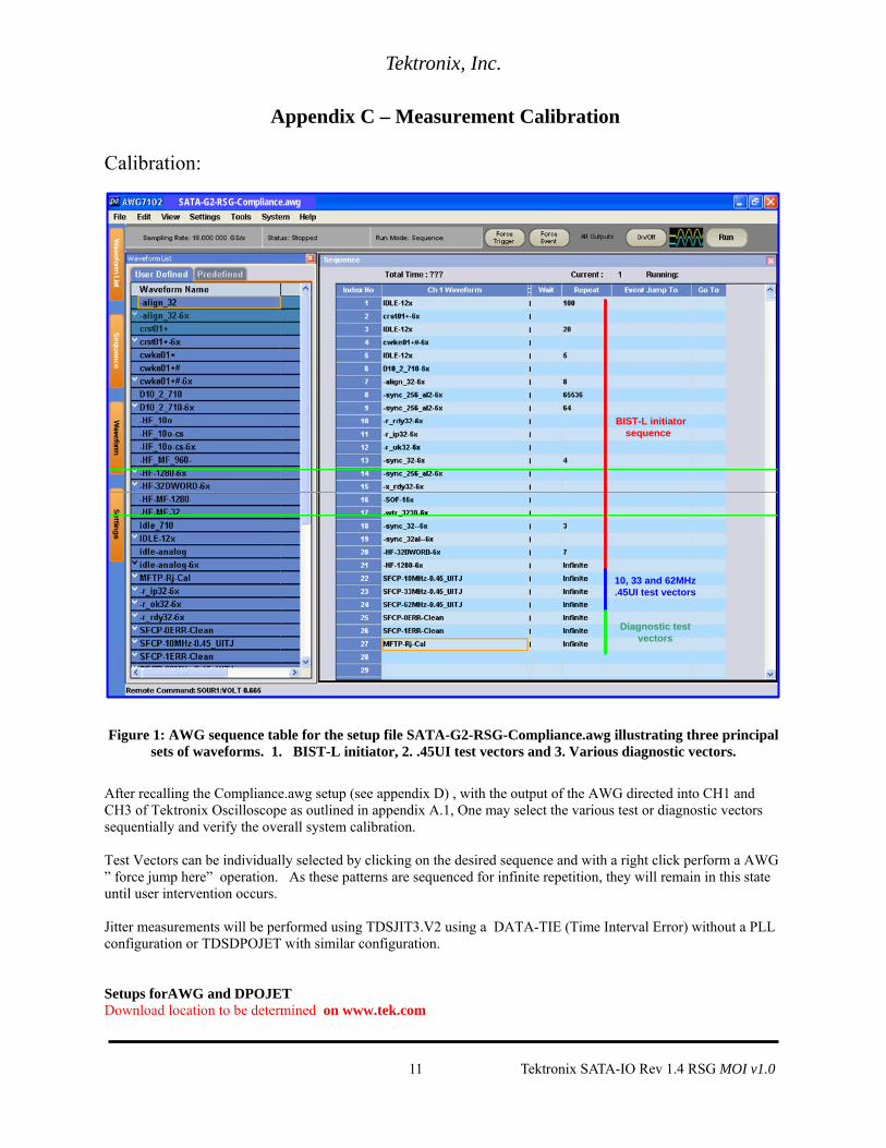
Appendix C – Measurement Calibration Calibration:
10, 33 and 62MHz .45UI test vectors
Diagnostic test vectors
SATA-G2-RSG-Compliance.awg
BIST-L initiator sequence
Figure 1: AWG sequence table for the setup file SATA-G2-RSG-Compliance.awg illustrating three principal sets of waveforms. 1. BIST-L initiator, 2. .45UI test vectors and 3. Various diagnostic vectors.
After recalling the Compliance.awg setup (see appendix D) , with the output of the AWG directed into CH1 and CH3 of Tektronix Oscilloscope as outlined in appendix A.1, One may select the various test or diagnostic vectors sequentially and verify the overall system calibration. Test Vectors can be individually selected by clicking on the desired sequence and with a right click perform a AWG ” force jump here” operation. As these patterns are sequenced for infinite repetition, they will remain in this state until user intervention occurs. Jitter measurements will be performed using TDSJIT3.V2 using a DATA-TIE (Time Interval Error) without a PLL configuration or TDSDPOJET with similar configuration. Setups forAWG and DPOJET Download location to be determined on www.tek.com
11 Tektronix SATA-IO Rev 1.4 RSG MOI v1.0

Tektronix, Inc.
Definition of specific test points for calibration C.1 Transition Time Validation The transition time measurement should be made on TP1 before jitter components are added. A LFTP pattern is used as the generators test pattern. The same DPOJET setup files used for Jitter calibration/validation have Rise and Fall time measurements which allow the user to validate that the transition rate is approximately 100ps 20%/80% for Gen1i & Gen2i and 62ps-75ps 20%/80% for Gen3i. Gen1 RMS Gen2 RMS Gen3i RMS Nominal 100pSec 100pSec 62-75ps
DPOJET screen-shot of Gen3i LFTP Rise Time Measurement. C.2 Rj Verification A reference Gen1, Gen2 and Gen3 MFTP pattern (MFTP-Rj-Cal.wfm) is provided in the AWG bases RSG waveform library support package to facilitate verification of calibration of Rj. Rj is specified to be .18UI PtP @ 7 Sigma or 8.57pSec RMS for Gen1, 4.285pSec for Gen2 and 2.14ps for Gen3. The RJ found in the Tektronix AWG MFTP pattern has been synthesized and is a truncated Gaussian distribution with the truncation occurring at 4.7 Sigma. This amount of Rj has been verified to correlate well to the 95% effective BER Rj. If additional Rj performance is desirable, users can effectively increase the crest factor by incorporating the use of an External Rj source added as part of the test setup. (See appendix F for additional information) Or by using a sequencing technique built into the AWG that can expand the apparent memory of the waveform by concatenating different seeds of Rj waveforms to effectively produce a much higher crest factor.
12 Tektronix SATA-IO Rev 1.4 RSG MOI v1.0

Tektronix, Inc.
Before performing the Rj calibration verification process, perform a SPC calibration on the Tektronix oscilloscope used and perform a D/A channel calibration on the AWG to ensure instrument environmental conditions have been compensated for.
Fig 2 DPOJET screenshot of Rj values of MFTP for Gen3i. As is illustrated in the red circled area of Figure 2, ensure the averaged Rj is nominally reading according to table below. The provided setup files will analyze 16E6 contiguous points per measurement, and 3 runs will typically converge on a averaged RJ. Jitter magnitudes in excess of these values should result in re-calibration of the AWG. Gen1 RMS Gen2 RMS Gen3i RMS Nominal 8.57pSec 4.285ps 2.14ps Min 8.22ps 4.11ps 2.05ps Max 8.9ps 4.45ps 2.22ps
C.3 Pj Verification A reference Gen1, Gen2 and Gen3 MFTP pattern (MFTP-Pj-Cal.wfm) is provided in the AWG RSG waveform library support package to facilitate verification of calibration of Sj. Gen1 Gen2 Gen3i Nominal .270 UI .270 UI .192 UI
13 Tektronix SATA-IO Rev 1.4 RSG MOI v1.0

Tektronix, Inc.
C.4 Tj Verification The required test waveforms for Gen1, Gen2 and Gen3 have been pre-synthesized using the Frame Comp pattern and are provided in the AWG based RSG waveform library support package. These base patterns conform to the IW sanctioned Framed Composite pattern outline in the SATA Pretest MOI. These waveforms include the required jitter components including Rj, Pj and DDj which includes the ISI/ CIC requirements. Gen1i and Gen2i are comprised using an ISI of 40ps, Gen3i requires using the CIC as defined in section 7.2.7 of SATA 3.0 Specification. After instructing the AWG sequencer to step to any of the provided RSG01_xxMHz_V1_4 test vectors for Gen1, RSG02_xxMHz_V1_4 test vector for Gen2 or RSG03_xxMHz_V1_4 test vectors for Gen3. DPOJET should be run. Observe the averaged Total @ BER (Pk-Pk) Jitter value after three acquisitions. The nominal accuracy of a calibrated system will provide Tj conformance within 4% of nominal error. Gen1 ps UI Gen2 ps UI Gen3i ps UI Min 327.67ps .501 177.82ps .552 82.67ps .498 Max 345.65ps .519 195.80ps .588 94.62ps .570
Fig 3 DPOJET screen-shot Gen3i of TJ measurement of full jitter profile.
14 Tektronix SATA-IO Rev 1.4 RSG MOI v1.0

Tektronix, Inc.
C.4 Amplitude Calibration The Amplitude measurement is done at TP2 using a Eye Opening measurement at 50% of UI with all TIE jitter components calibrated previously on the Frame Comp LBP. This technique is defined in Sec7.4.3 and 7.4.12 of SATA 3.0 Specification. This measurement is used for all data rates where limits are listed in table below: Gen1i Gen1m/x Gen2i Gen2m/x Gen3i Min 325mV 240mV 275mV 240mV 240mV
Purpose: To verify that the Differential Output Voltage of the PUT’s transmitter is within the conformance limits for all PUTs. References:
[1] Sec7.4.3 and 7.4.12 of SATA 3.0 Specification. [2] Ibid, 7.4.3.2 – Minimum Differential Voltage Amplitude (Gen3i) [3] SATA Unified Test Document, UTD_1.4
Resource Requirements: See Appendix A Discussion:
Reference [1] specifies the Transmitted Signal conformance limits for SATA generated signal. This specification includes conformance limits for the Minimum Differential Voltage Amplitude. Reference [2] provides the definition of this term for the purposes of SATA testing. Reference [3] defines the measurement requirements for this test.
Test Setup:
Connect equipment as shown in Appendix B, figure 1 or 2 as appropriate. Note that it is acceptable to use either differential or pseudo-differential (single ended plus math waveform) probes for these measurements. Recall Scope and DPOJET vertical cal setup. Test Procedure:
Using techniques and equipment as described in Appendix A of the PRE-TEST MOI, or equivalent, place the PUT in BISTFIS mode transmitting compliant Frame Comp LBP pattern including jitter and CIC component. Depending on the capability of the PUT, and the equipment available, it is acceptable to use either BIST-T or BIST-L to produce the needed test pattern. If the PUT supports disconnects, remove the SATA PRE-TEST system, and connect SATA test fixture. Some PUTs require that the connection not be broken after BIST has been activated. In these situations, it may be necessary to use power splitters to allow simultaneous connection of the PRE-TEST system and the test equipment. Refer to Appendix A of the PRE-TEST MOI for additional details. Start DPOJET to capture the waveform.. A measurement is taken of the High and Low amplitude values of the middle of the eye opening of the resulting signal. The results are fitted into linear plots (e.g. Transformation Q) which are extrapolated out to 1E^-12 BER. The difference between High and Low amplitudes at 1E^-12 BER are evaluated and compared to the Pass/Fail Criteria (Table 7-3 of Serial ATA Revision 2.6) Test pattern(s): Frame Comp LBP with all jitter/CIC included (SSC optional)
SATA usage model: (Gen1-Gen3)
Observable Results:
15 Tektronix SATA-IO Rev 1.4 RSG MOI v1.0

Tektronix, Inc.
The differential voltage [(TX+) – (TX-)] measured at the TP2 shall comply with the respective electrical specifications of section 7.2 of the SATA specification Gen1i Gen1m/x Gen2i Gen2m/x Gen3i Min 325mV 240mV 275mV 240mV 240mV
16 Tektronix SATA-IO Rev 1.4 RSG MOI v1.0

Tektronix, Inc.
Appendix D – AWG-7000 Setups The AWG-7000 (with Option 6) arbitrary waveform generator is capable of regenerating a SATA Framed Composite pattern with prescribed amount of random and deterministic jitter. These synthesized waveforms are encapsulated in a series of setup files which will recall the waveform pattern to generate, set the proper AWG time-base settings and set the vertical drive amplitude accordingly. Properly calibrated AWG instruments will exhibit an instrument to instrument difference of less than 4% variation. These AWG setup files reflect framed composite patters with five different jitter configurations modulated onto the clean pattern. For Gen1 and Gen2 the Total Jitter observed on these patterns will be .5UI of jitter with .32UI of Deterministic/Sinusoidal jitter and .18UI of Random jitter. The mean transition time for these signals is set to 120pSec, and the signal amplitude set to 325mV ppd (Gen1) or 275mV ppd (Gen2) and 275mV for ESATA. For Gen3i the Total Jitter observed on these patterns will be .57UI of jitter with .42UI of Deterministic/Sinusoidal and ISI jitter and .18UI of Random jitter. The mean transition time for these signals is set between 62ps – 75ps, and the signal amplitude set between a min of 240mV ppd. D.1 SATA 1.5Gb/Sec AWG7000 setup file descriptions. AWG7000 SATA- RSG-01_V1_4_Compliance.zip
D.2 SATA 3.0Gb/Sec AWG7000 setup file descriptions. AWG7000 SATA- RSG-02_V1_4_Compliance.zip
D.3 SATA 6.0Gb/Sec AWG7000 setup file descriptions. AWG7122B SATA- RSG-03_V1_4_Compliance.zip
D.4 SATA 1.5Gb/Sec AWG7000 setup file descriptions. AWG7000 SATA- RSG-05_V1_4_Compliance.zip D.5 SATA 1.5Gb/Sec AWG7000 setup file descriptions. AWG7000 SATA- RSG-06_V1_4_Compliance.zip
17 Tektronix SATA-IO Rev 1.4 RSG MOI v1.0

Tektronix, Inc.
Test pattern setup file for RSG-01: Normative, Required for all PUTs. AWG7000 SATA- RSG-01_V1_4Compliance.zip
SATA usage model: 1.5Gbps(Gen1i)
Test time/PJ freq waveform RSG01a 10Mhz 10 Min RSG01b 33Mhz 10 Min RSG01c 62Mhz 10 Min RSG01d 5Mhz 10 Min
Test pattern setup file for RSG-02: Normative, Required for PUTs claiming ability to run Gen2i and Gen3i rates. AWG7000 SATA- RSG-02_V1_4Compliance.zip
SATA usage model: 3Gbps(Gen2i) + 0ppm
Test time/PJ freq waveform RSG02a 10Mhz 5 Min RSG02b 33Mhz 5 Min RSG02c 62Mhz 5Min RSG02d 5Mhz 5 Min
Test pattern setup file for RSG-03: Informative, Required for PUTs claiming ability to run Gen3i rates. AWG7122B SATA- RSG-03_V1_4Compliance.zip
SATA usage model: 6Gbps(Gen3i) +0ppm
Test time/PJ freq waveform RSG03a 10Mhz 2.5 Min RSG03b 33Mhz 2.5 Min RSG03c 62Mhz 2.5Min RSG03d 5Mhz 2.5 Min
Test pattern setup file for RSG-05: Normative, Required for all PUTs. AWG7000 SATA- RSG-05_V1_4Compliance.zip
SATA usage model: 1.5Gbps + 350ppm
Test time/PJ freq waveform >= 18 successive iterations of Frame COMP wfm. With only 62MHz Pj component
Test pattern setup file for RSG06: Informative, Required for all PUTs. AWG7000 SATA- RSG-06_V1_4Compliance.zip
SATA usage model: 1.5Gbps - 350ppm with ideal 5000ppm triangular downspread SSC at 33KHz modulation freq. Data Rate Range is between 1.5 Gb/s – 5350ppm and 1.5 Gb/s -350ppm.
Test time/PJ freq waveform >= 18 successive iterations of Frame COMP wfm. With only 62MHz Pj component
18 Tektronix SATA-IO Rev 1.4 RSG MOI v1.0

Tektronix, Inc.
Appendix E – Frame Error Detectors
(Crescent Heart Software SATA-II Probe Adapter for Gen1 & Gen2 only)
As outlined in Section 9.8 of the SATA-II users’ manual, install the SATA-II control application on any host PC or instrument in proximity to the PUT. The SATA-II probe adapter must be powered using the provided DC power supply, and attached via USB cable to the host PC running the control application. After invoking the software the application’s main window will be seen, as in Figure A.
The controls in the middle column set as shown above are appropriate for any simple Gen-I FER counting objective outlined in this MOI. For Gen-II use, the Initial Host Rx speed Gen2 and Initial Device Rx speed Gen2 checkboxes should also be enabled.
A – SATA-II Main Window
Select Counters on the View pull down menu and the Counters window will be displayed, as seen in Figure B.
19 Tektronix SATA-IO Rev 1.4 RSG MOI v1.0

Tektronix, Inc.
B – SATA-II Counters Window
Ensure that the periodic update checkbox is checked and 40-bit count statistics will be automatically updated when the events occur.
20 Tektronix SATA-IO Rev 1.4 RSG MOI v1.0

Tektronix, Inc.
(Finisar Xgig with Performance Monitor) Gen1-Gen3
Finisar Xgig for Gen1- Gen3i Xgig-C042 (qty 1): Four Slot Portable or Rack mountable Chassis Xgig-B860Sc: 6 Gb/s SAS/SATA Wide Port Blade with mini SAS connectors, 16 GB memory, w/ Link Extender (LE) Xgig-S86AS: Wide-Port 6Gb/s SAS/SATA Analyzer Function Key (8 ports / 4 links) Performance Monitor SW
Load the performance Monitor SW on PC or directly on the AWG. Make sure the chassis is connected to distributed internet that is also connected to the host PC or AWG. Run the performance monitor SW and follow the Xgig user guide to get started. Once the domain has been selected.
Setup display as below to perform single error test. Once it has been established that the FEC is counting correctly, start a new capture and run test for prescribed amount of time.
(SerialTek BusXpert Micro Analyzer) Gen1-Gen3
21 Tektronix SATA-IO Rev 1.4 RSG MOI v1.0

Tektronix, Inc.
SerialTek BusXpert Micro Analyzer Gen1- Gen3i MA-2x6SA-2GB BusXpert Micro Analyzer, 2-port, 6Gb/s SAS/SATA, 2.25GB Buffer, Advanced Triggering and Segmented Buffer BusXpert SW
Load the BusXpert W on PC or directly on the AWG. Make sure the chassis is connected to distributed internet that is also connected to the host PC or AWG. Run the BusXpert SW and follow the user guide to get started. Once the instrument has been selected. SetupCapture Control for manual stop and within trigger setup drag Any FIS into the New Sequencer dialog as below.
22 Tektronix SATA-IO Rev 1.4 RSG MOI v1.0

Tektronix, Inc.
Select ATA OUTput Error and select Items as in next image.
Drag it into the Add Select Event dialog. Use status menu to validate error counting
Once it has been established that the FEC is counting correctly, start a new capture and run test for prescribed amount of time.
23 Tektronix SATA-IO Rev 1.4 RSG MOI v1.0

Tektronix, Inc.
Appendix F – J9005A External Rj Source
Reference Data Sheet at: ftp://ftp.tektronix.com/outgoing/NOISE_COM_J79005A_Datasheet_PR.pdf The J9005A instrument from Noisecom is designed to work in conjunction with the Tektronix differential Arbitrary Waveform Generator to provide random jitter during compliance testing.
ktronix differential Arbitrary Waveform Generator to provide random jitter during compliance testing. The J9005A has a high crest factor output, > 7 σ, to emulate very low BER occurrences. True analog white Gaussian noise does not repeat, like Pseudo-random digital noise, and is truly The J9005A has a high crest factor output, > 7 σ, to emulate very low BER occurrences. True analog white Gaussian noise does not repeat, like Pseudo-random digital noise, and is truly random. Analog noise will cover the full signal BW, and not fall short for today’s Serial Data signal requirements random. Analog noise will cover the full signal BW, and not fall short for today’s Serial Data signal requirements
Ch1 Ch2
Tek DSA
Ch1+
Ch1 –
Tek AWG
DPOJET
AWG7122 opt06, opt 08
DUT Rx+
Rx-
Tx+
Tx-
Rx+
Rx-
SMA
SMA
SMA
Silicon
Power Divider
SMA Cable LAN/USB
FEC
SMA Test Fixture
J9005A
SATA I,II, III- Finisar, SerialTek SATA I, II CHS SMA
Test Fixture
Setup includes the J9005A in the transmission path from AWG to DUT calibrated waveforms are provided in the compliance waveform package that enable use of this Rj source.
24 Tektronix SATA-IO Rev 1.4 RSG MOI v1.0

Tektronix, Inc.
Appendix G – Arbitrary Waveform Generator Accuracy Tables F.1 outline the system and individual measurement accuracy parameters for the SATA measurements outlined in his MOI when performed using a AWG 7000 Arbitrary Waveform Generator. Table F.2 Measurement specific performance parameters for current IW RSG measurements.
Spec number
Measurement Accuracy Notes:
RSG-01 Receiver
1.5Gb/Sec TBD. TBD.
RSG-02 Receiver 3.0Gb/Sec
TBD. TBD.
RSG-03 Receiver 6.0Gb/Sec
TBD. TBD.
RSG-05 Receiver 1.5Gb/Sec
TBD. TBD.
RSG-06 Receiver 1.5Gb/Sec
TBD. TBD.
25 Tektronix SATA-IO Rev 1.4 RSG MOI v1.0