Embed Size (px)
Citation preview

SERCOS Manual
Servo positioning controller ARS 2000
Metronix Meßgeräte und Elektronik GmbH Phone: +49-(0)531-8668-0 Kocherstraße 3 Fax: +49-(0)531-8668-555
D-38120 Braunschweig E-mail: [email protected]
Germany http://www.metronix.de

Seite 2
Copyrights
© 2006 Metronix Meßgeräte und Elektronik GmbH. All rights reserved.
The information and data in this document have been composed to the best of our knowledge. However, deviations between the document and the product cannot be excluded entirely. For the devices and the corresponding software in the version handed out to the customer, Metronix guarantees the contractual use in accordance with the user documentation. In the case of serious deviations from the user documentation, Metronix has the right and the obligation to repair, unless it would involve an unreasonable effort. A possible liability does not include deficiencies caused by deviations from the operating conditions intended for the device and described in the user documentation.
Metronix does not guarantee that the products meet the buyer’s demands and purposes or that they work together with other products selected by the buyer. Metronix does not assume any liability for damages resulting from the combined use of its products with other products or resulting from improper handling of machines or systems.
Metronix Meßgeräte und Elektronik GmbH reserves the right to modify, amend, or improve the document or the product without prior notification.
This document may, neither entirely nor in part, be reproduced, translated into any other natural or machine-readable language nor transferred to electronic, mechanical, optical or any other kind of data media, without expressive authorisation by the author.
Trademarks
Any product names in this document may be registered trademarks. The sole purpose of any trademarks in this document is the identification of the corresponding products.
ServoCommander™ is a registered trademark of Metronix Meßgeräte und Elektronik GmbH.
SERCOS interface® is a registered trademark of Interests Group SERCOS interface e.V

Seite 3
Revision log
Authors: Metronix Meßgeräte und Elektronik GmbH
Name of manual: SERCOS Manual „Servo positioning controller ARS 2000“
Filename: Sercos_Manual_ARS2000_V1p1.doc
Consec. no
Description Revisions-index
Date of revision
001 Release for distribution 1.0 31.05.2005
002 Release 1.1 03.02.2006
003 New IDNs of Product Step 3.3 1.2
SERCOS Manual ”Servo positioning controller ARS 2000” Version 1.2

Seite 4
TABLE OF CONTENTS
1 GENERAL TERMS .............................................................................................9
1.1 Documentation .........................................................................................9
1.2 SErial Realtime COmmunication System ...............................................10
2 SAFETY NOTES FOR ELECTRICAL DRIVES AND CONTROLS...................11
2.1 Symbols and signs .................................................................................11
2.2 General notes .........................................................................................12
2.3 Danger resulting from misuse.................................................................13
2.4 Safety notes............................................................................................14 2.4.1 General safety notes..................................................................14 2.4.2 Safety notes for assembly and maintenance .............................15 2.4.3 Protection against contact with electrical parts ..........................16 2.4.4 Protection against electrical shock by means of protective extra-
low voltage (PELV) ....................................................................17 2.4.5 Protection against dangerous movements.................................18 2.4.6 Protection against contact with hot parts ...................................19 2.4.7 Protection during handling and assembly ..................................19
3 CABLING AND PIN ASSIGNMENT .................................................................21
3.1 Pin assignment .......................................................................................21
4 ACTIVATION OF SERCOS ..............................................................................22
4.1 Survey 22
4.2 Available Baudrates................................................................................23
5 OVERVIEW.......................................................................................................24
5.1 Survey 24
5.2 Axis telegram (AT)..................................................................................25
5.3 Master data telegram (MDT)...................................................................26
5.4 Service Channel (SC) .............................................................................26
5.5 Telegram types.......................................................................................28 5.5.1 Standard telegrams....................................................................28
5.5.1.1 Standard telegram 0 ..............................................................................28 5.5.1.2 Standard telegram 1 ..............................................................................28 5.5.1.3 Standard telegram 3 ..............................................................................28 5.5.1.4 Standard telegram 4 ..............................................................................28
Version 1.2 SERCOS Manual ”Servo positioning controller ARS 2000”

Seite 5
5.5.2 Application telegram ..................................................................29
5.6 Initialisation (Phase transitions) ..............................................................30 5.6.1 CP0: Close the ring....................................................................30 5.6.2 CP1: Identify the Axes ...............................................................30 5.6.3 CP2: Load communication parameters......................................30 5.6.4 CP3: Load application parameters.............................................31 5.6.5 CP4: Cyclic operation ................................................................31
6 SERCOS CYCLE TIME ....................................................................................32
7 OPERATION MODES.......................................................................................34
7.1 Torque control ........................................................................................35
7.2 Velocity control .......................................................................................35
7.3 Position control .......................................................................................35
7.4 Drive controlled interpolation ..................................................................35
8 SCALING OF DATA .........................................................................................37
8.1 Position data...........................................................................................37 8.1.1 Overview....................................................................................37 8.1.2 No scaling ..................................................................................38 8.1.3 Linear scaling.............................................................................38 8.1.4 Rotational scaling.......................................................................38
8.2 Velocity data ...........................................................................................39 8.2.1 Overview....................................................................................39 8.2.2 No scaling ..................................................................................40 8.2.3 Linear scaling.............................................................................40 8.2.4 Rotational scaling.......................................................................40
8.3 Acceleration data....................................................................................41 8.3.1 Overview....................................................................................41 8.3.2 No scaling ..................................................................................42 8.3.3 Linear scaling.............................................................................42 8.3.4 Rotational scaling.......................................................................42
8.4 Torque data ............................................................................................42
8.5 Temperature data ...................................................................................42
9 CONTROLWORD / STATUSWORD ................................................................43
10 ERROR MANAGEMENT ..................................................................................46
11 IO- FUNCTIONS ...............................................................................................47
SERCOS Manual ”Servo positioning controller ARS 2000” Version 1.2

Seite 6
12 SPECIAL COMMANDS ....................................................................................48
12.1 Drive controlled homing..........................................................................48
12.2 Spindle positioning..................................................................................50
12.3 Probing (Measurement) ..........................................................................51
12.4 Automatic motoridentification..................................................................52
13 PARAMETERS.................................................................................................53
13.1 Survey 53
13.2 Communication parameters....................................................................53
13.3 Telegram configuration...........................................................................58
13.4 IDN lists / Phase switching commands...................................................60
13.5 Operation modes ....................................................................................63
13.6 Scaling parameters.................................................................................64
13.7 Command / Feedback values .................................................................69
13.8 Limitation / Monitoring ............................................................................72
13.9 Signal statusword / Realtime bits............................................................76
13.10 Statusbits................................................................................................80
13.11 Automatic identification...........................................................................84
13.12 Error management..................................................................................86
13.13 IO- Functions ..........................................................................................87
13.14 Drive controlled homing..........................................................................90
13.15 Drive controlled interpolation ..................................................................93
13.16 Probing 94
13.17 Spindle positioning..................................................................................97
13.18 Miscellanous...........................................................................................99
13.19 Informations..........................................................................................101
13.20 Diagnostic Classes ...............................................................................104 13.20.1 Class 1 diagnostic (C1D) .........................................................104 13.20.2 Manufacturer class 1 diagnostic...............................................105 13.20.3 IDN S-0-0095: Diagnostic Message.........................................106 13.20.4 Class 2 diagnostic (C2D) .........................................................106 13.20.5 Class 3 diagnostic (C3D) .........................................................107 13.20.6 Manufacturer Class 3 diagnostic (C3D) ...................................108 13.20.7 IDN S-0-0014: „Interface Status“ .............................................109 13.20.8 Diagnostics masks ...................................................................110
Version 1.2 SERCOS Manual ”Servo positioning controller ARS 2000”

Seite 7
14 SERCOS ERROR CODES .............................................................................111
15 APPENDIX......................................................................................................113
16 PARAMETER INDEX .....................................................................................114
16.1 By name ...............................................................................................114
16.2 By IDN 116
SERCOS Manual ”Servo positioning controller ARS 2000” Version 1.2

Seite 8 General Terms
TABLE OF FIGURES Figure 3.1: SERCOS plug-in module for ARS 2000........................................................21 Figure 3.2: Plug-in position for ARS 2102, 2105, 2302, 2305 and 2310.........................21 Figure 3.3: Plug-in position for ARS 2320 and 2340.......................................................21 Figure 5.4: Cyclic data exchange....................................................................................24 Figure 5.5: Axis telegram (AT) ........................................................................................26 Figure 5.6: Master data telegram (MDT).........................................................................26 Figure 5.7: Phase transitions ..........................................................................................30 Figure 8.8: Position data scaling.....................................................................................37 Figure 8.9: Velocity data scaling .....................................................................................39 Figure 8.10: Acceleration data scaling..............................................................................41 Figure 12.1: Reference point ............................................................................................48 Figure 15.2: Connection of transmitter diode..................................................................113
Version 1.2 SERCOS Manual ”Servo positioning controller ARS 2000”

General Terms Seite 9
1 General Terms
1.1 Documentation
This manual describes the fieldbus connection of ARS 2000 servo positioning controllers under SERCOS. It describes briefly the protocol itself, the activation of the SERCOS communication and the parameter available under SERCOS.
It is intended to persons who are already familiar with the servo positioning controller series and the SERCOS protocol.
It contains safety notes that have to be noticed.
For more informations, please refer to the following manuals of the ARS 2000 series products:
Software Manual “Servo Positioning Controller ARS 2000”: Description of the device functionality and the software functions of the firmware including RS232 communication. Description of the parameterisation program Metronix ServoCommander™ with instructions on the commissioning of an ARS 2000 series servo positioning controller.
Product Manual “Servo Positioning Controller ARS 2100”: Description of the technical specifications and the device functionality as well as notes on the installation and the operation of the servo positioning controller ARS 2100.
Product manual "Servo Positioning Controller ARS 2302 - 2310": Description of the technical data and the device functionality plus notes concerning the installation and operation of ARS 2302, 2305 and 2310 servo positioning controllers.
Product manual "Servo Positioning Controller ARS 2320 and 2340": Description of the technical data and the device functionality plus notes concerning the installation and operation of ARS 2320 and 2340 servo positioning controllers.
CANopen Manual “Servo Positioning Controller ARS 2000“: Description of the implemented CANopen protocol as per DSP402.
PROFIBUS Manual “Servo Positioning Controller ARS 2000”: Description of the implemented PROFIBUS-DP protocol.
Ethernet Manual “Servo Positioning Controller ARS 2000”: Description of the implemented Ethernet protocol.
SERCOS Manual “Servo positioning controller ARS 2000” Version 1.2

Seite 10 General Terms
1.2 SErial Realtime COmmunication System
SERCOS interface, the unique worldwide standardised (IEC 61491 and EN61491) digital interface for a communication between control systems and drives. It was the first fieldbus system that allowed the realization of numerically controlled high-performance applications in the machine tool engineering.
An optical fiber ring is used as transmission medium. The transmission rate is 2, 4, 8 or 16 Mbit/s.
Basically three communications types between CNC and digital drive control elements can be realised with this interface:
• transmission of nominal position
• transmission of nominal speed or
• transmission of nominal torque
The transmission of the nominal position proved to be the best solution for fast and highly precise applications. In one optical fiber ring up to 6 axes can be cyclically and parallel supplied with new nominal positions values (nominal positions) every 0,5 ms
The SERCOS interface allows all drive-internal data, parameters and diagnosis data to be displayed and entered by means of a SERCOS-compatible CNC.
For further informations and specifications regarding SERCOS please refer to:
http://www.sercos.org/
Interests Group SERCOS interface e.V. Landhausstrasse 20, 70190 Stuttgart
Germany
Version 1.2 SERCOS Manual ”Servo positioning controller ARS 2000”

Safety Notes for electrical drives and controls Seite 11
2 Safety Notes for electrical drives and controls
2.1 Symbols and signs
Information Important informations and notes.
Caution! The nonobservance can result in high property damage.
DANGER! The nonobservance can result in property damages and in injuries to persons.
Caution! High voltage. The note on safety contains a reference to a possibly occurring life dangerous voltage.
The parts of this document marked with this sign should give examples to make it easier to understand the use of single objects and parameters.
SERCOS Manual “Servo positioning controller ARS 2000” Version 1.2

Seite 12 Safety Notes for electrical drives and controls
2.2 General notes
In the case of damage resulting from non-compliance of the safety notes in this manual Metronix Meßgeräte und Elektronik GmbH will assume any liability.
Prior to the initial use you must read the chapters Safety Notes for electrical drives and controls starting on page 11
If the documentation in the language at hand is not understood accurately, please contact and inform your supplier.
Sound and safe operation of the servo drive controller requires proper and professional transportation, storage, assembly and installation as well as proper operation and maintenance. Only trained and qualified personnel may handle electrical devices:
TRAINED AND QUALIFIED PERSONNEL
in the sense of this product manual or the safety notes on the product itself are persons who are sufficiently familiar with the setup, assembly, commissioning and operation of the product as well as all warnings and precautions as per the instructions in this manual and who are sufficiently qualified in their field of expertise:
Education and instruction or authorisation to switch devices/systems on and off and to ground them as per the standards of safety engineering and to efficiently label them as per the job demands.
Education and instruction as per the standards of safety engineering regarding the maintenance and use of adequate safety equipment.
First aid training.
The following notes must be read prior to the initial operation of the system to prevent personal injuries and/or property damages:
These safety notes must be complied with at all times.
Do not try to install or commission the servo drive controller before carefully reading all safety notes for electrical drives and controllers contained in this document. These safety instructions and all other user notes must be read prior to any work with the servo drive controller.
In case you do not have any user notes for the servo positioning controller, please contact your sales representative. Immediately demand these documents to be sent to the person responsible for the safe operation of the servo drive controller.
If you sell, rent and/or otherwise make this device available to others, these safety notes must also be included.
Version 1.2 SERCOS Manual ”Servo positioning controller ARS 2000”

Safety Notes for electrical drives and controls Seite 13
The user must not open the servo drive controller for safety and warranty reasons.
Professional control process design is a prerequisite for sound functioning of the servo drive controller!
DANGER!
Inappropriate handling of the servo drive controller and non-compliance of the warnings as well as inappropriate intervention in the safety features may result in property damage, personal injuries, electric shock or in extreme cases even death.
2.3 Danger resulting from misuse
DANGER!
High electrical voltages and high load currents!
Danger to life or serious personal injury from electrical shock!
DANGER!
High electrical voltage caused by wrong connections!
Danger to life or serious personal injury from electrical shock!
DANGER!
Surfaces of device housing may be hot!
Risk of injury! Risk of burning!
DANGER!
Dangerous movements!
Danger to life, serious personal injury or property damage due to unintentional movements of the motors!
SERCOS Manual “Servo positioning controller ARS 2000” Version 1.2

Seite 14 Safety Notes for electrical drives and controls
2.4 Safety notes
2.4.1 General safety notes
The servo drive controller corresponds to IP20 class of protection as well as pollution level 1. Make sure that the environment corresponds to this class of protection and pollution level.
Only use replacements parts and accessories approved by the manufacturer.
The devices must be connected to the mains supply as per EN regulations, so that they can be cut off the mains supply by means of corresponding separation devices (e.g. main switch, contactor, power switch).
The servo drive controller may be protected using an AC/DC sensitive 300mA fault current protection switch (RCD = Residual Current protective Device).
Gold contacts or contacts with a high contact pressure should be used to switch the control contacts.
Preventive interference rejection measures should be taken for control panels, such as connecting contactors and relays using RC elements or diodes.
The safety rules and regulations of the country in which the device will be operated must be complied with.
The environment conditions defined in the product documentation must be kept. Safety-critical applications are not allowed, unless specifically approved by the manufacturer.
For notes on installation corresponding to EMC, please refer to Product Manual ARS 2100. The compliance with the limits required by national regulations is the responsibility of the manufacturer of the machine or system.
The technical data and the connection and installation conditions for the servo drive controller are to be found in this product manual and must be met.
DANGER!
The general setup and safety regulations for work on power installations (e.g. DIN, VDE, EN, IEC or other national and international regulations) must be complied with.
Non-compliance may result in death, personal injury or serious property damages.
Version 1.2 SERCOS Manual ”Servo positioning controller ARS 2000”

Safety Notes for electrical drives and controls Seite 15
Without claiming completeness, the following regulations and others apply:
VDE 0100 Regulations for the installation of high voltage (up to 1000 V) devices
EN 60204 Electrical equipment of machines
EN 50178 Electronic equipment for use in power installations
2.4.2 Safety notes for assembly and maintenance
The appropriate DIN, VDE, EN and IEC regulations as well as all national and local safety regulations and rules for the prevention of accidents apply for the assembly and maintenance of the system. The plant engineer or the operator is responsible for compliance with these regulations:
The servo drive controller must only be operated, maintained and/or repaired by personnel trained and qualified for working on or with electrical devices.
Prevention of accidents, injuries and/or damages:
Additionally secure vertical axes against falling down or lowering after the motor has been switched off, e.g. by means of:
Mechanical locking of the vertical axle,
External braking, catching or clamping devices or
Sufficient balancing of the axle.
The motor holding brake supplied by default or an external motor holding brake driven by the drive controller alone is not suitable for personal protection!
Render the electrical equipment voltage-free using the main switch and protect it from being switched on again until the DC bus circuit is discharged, in the case of:
Maintenance and repair work
Cleaning
long machine shutdowns
Prior to carrying out maintenance work make sure that the power supply has been turned off, locked and the DC bus circuit is discharged.
The external or internal brake resistor carries dangerous DC bus voltages during operation of the servo drive controller and up to 5 minutes thereafter. Contact may result in death or serious personal injury.
Be careful during the assembly. During the assembly and also later during operation of the drive, make sure to prevent drill chips, metal dust or assembly parts (screws, nuts, cable sections) from falling into the device.
SERCOS Manual “Servo positioning controller ARS 2000” Version 1.2

Seite 16 Safety Notes for electrical drives and controls
Also make sure that the external power supply of the controller (24V) is switched off.
The DC bus circuit or the mains supply must always be switched off prior to switching off the 24V controller supply.
Carry out work in the machine area only, if AC and/or DC supplies are switched off. Switched off output stages or controller enablings are no suitable means of locking. In the case of a malfunction the drive may accidentally be put into action.
Initial operation must be carried out with idle motors, to prevent mechanical damages e.g. due to the wrong direction of rotation.
Electronic devices are never fail-safe. It is the user’s responsibility, in the case an electrical device fails, to make sure the system is transferred into a secure state.
The servo drive controller and in particular the brake resistor, externally or internally, can assume high temperatures, which may cause serious burns.
2.4.3 Protection against contact with electrical parts
This section only concerns devices and drive components carrying voltages exceeding 50 V. Contact with parts carrying voltages of more than 50 V can be dangerous for people and may cause electrical shock. During operation of electrical devices some parts of these devices will inevitably carry dangerous voltages.
DANGER!
High electrical voltage!
Danger to life, danger due to electrical shock or serious personal injury!
The appropriate DIN, VDE, EN and IEC regulations as well as all national and local safety regulations and rules for the prevention of accidents apply for the assembly and maintenance of the system. The plant engineer or the operator is responsible for compliance with these regulations:
Version 1.2 SERCOS Manual ”Servo positioning controller ARS 2000”

Safety Notes for electrical drives and controls Seite 17
Before switching on the device, install the appropriate covers and protections against accidental contact. Rack-mounted devices must be protected against accidental contact by means of a housing, e.g. a switch cabinet. The regulations VBG 4 must be complied with!
Always connect the ground conductor of the electrical equipment and devices securely to the mains supply. Due to the integrated line filter the leakage current exceeds 3.5 mA!
Comply with the minimum copper cross-section for the ground conductor over its entire length as per EN60617!
Prior to the initial operation, even for short measuring or testing purposes, always connect the ground conductor of all electrical devices as per the terminal diagram or connect it to the ground wire. Otherwise the housing may carry high voltages which can cause electrical shock.
Do not touch electrical connections of the components when switched on.
Prior to accessing electrical parts carrying voltages exceeding 50 Volts, disconnect the device from the mains or power supply. Protect it from being switched on again.
For the installation the amount of DC bus voltage must be considered, particularly regarding insulation and protective measures. Ensure proper grounding, wire dimensioning and corresponding short-circuit protection.
The device comprises a rapid discharge circuit for the DC bus as per EN60204 section 6.2.4. In certain device constellations, however, mostly in the case of parallel connection of several servo drive controllers in the DC bus or in the case of an unconnected brake resistor, this rapid discharge may be rendered ineffective. The servo drive controllers can carry voltage until up to 5 minutes after being switched off (residual capacitor charge).
2.4.4 Protection against electrical shock by means of protective extra-low voltage (PELV)
All connections and terminals with voltages between 5 and 50 Volts at the servo drive controller are protective extra-low voltage, which are designed safe from contact in correspondence with the following standards:
International: IEC 60364-4-41
European countries within the EU: EN 50178/1998, section 5.2.8.1.
SERCOS Manual “Servo positioning controller ARS 2000” Version 1.2

Seite 18 Safety Notes for electrical drives and controls
DANGER!
High electrical voltages due to wrong connections!
Danger to life, risk of injury due to electrical shock!
Only devices and electrical components and wires with a protective extra low voltage (PELV) may be connected to connectors and terminals with voltages between 0 to 50 Volts.
Only connect voltages and circuits with protection against dangerous voltages. Such protection may be achieved by means of isolation transformers, safe optocouplers or battery operation.
2.4.5 Protection against dangerous movements
Dangerous movements can be caused by faulty control of connected motors, for different reasons:
Improper or faulty wiring or cabling
Error in handling of components
Error in sensor or transducer
Defective or non-EMC-compliant components
Error in software in superordinated control system
These errors can occur directly after switching on the device or after an indeterminate time of operation.
The monitors in the drive components for the most part rule out malfunctions in the connected drives. In view of personal protection, particularly the danger of personal injury and/or property damage, this may not be relied on exclusively. Until the built-in monitors come into effect, faulty drive movements must be taken into account; their magnitude depends on the type of control and on the operation state.
DANGER!
Dangerous movements!
Danger to life, risk of injury, serious personal injuries or property damage!
For the reasons mentioned above, personal protection must be ensured by means of monitoring or superordinated measures on the device. These are installed in accordance with the specific data of the system and a danger and error analysis by the manufacturer. The safety regulations applying to the system are also taken into consideration. Random movements or other malfunctions may be caused by switching the safety installations off, by bypassing them or by not activating them.
Version 1.2 SERCOS Manual ”Servo positioning controller ARS 2000”

Safety Notes for electrical drives and controls Seite 19
2.4.6 Protection against contact with hot parts
DANGER!
Housing surfaces may be hot!
Risk of injury! Risk of burning!
Do not touch housing surfaces in the vicinity of heat sources! Danger of burning!
Before accessing devices let them cool down for 10 minutes after switching them off.
Touching hot parts of the equipment such as the housing, which contain heat sinks and resistors, may cause burns!
2.4.7 Protection during handling and assembly
Handling and assembly of certain parts and components in an unsuitable manner may under adverse conditions cause injuries.
DANGER!
Risk of injury due to improper handling!
Personal injury due to pinching, shearing, cutting, crushing!
The following general safety notes apply:
Comply with the general setup and safety regulations on handling and assembly.
Use suitable assembly and transportation devices.
Prevent incarcerations and contusions by means of suitable protective measures.
Use suitable tools only. If specified, use special tools.
Use lifting devices and tools appropriately.
SERCOS Manual “Servo positioning controller ARS 2000” Version 1.2

Seite 20 Safety Notes for electrical drives and controls
If necessary, use suitable protective equipment (e.g. goggles, protective footwear, protective gloves).
Do not stand underneath hanging loads.
Remove leaking liquids on the floor immediately to prevent slipping.
Version 1.2 SERCOS Manual ”Servo positioning controller ARS 2000”

Cabling and pin assignment Seite 21
3 Cabling and pin assignment
3.1 Pin assignment
Figure 3.1: SERCOS plug-in module for ARS 2000
In the ARS 2000 product range, the SERCOS interface has been realised in the form of an optional technological plug-in module. Due to special hardware requirements it can only be used at the TECH2- Slot.
In accordance with the SERCOS specification the transmitter HFE 7000-210 (plastic barrel) and the receiver HFD 7000-402 (metal barrel) are accesible at the front panel.
Figure 3.2: Plug-in position for ARS 2102, 2105, 2302, 2305 and 2310
Figure 3.3: Plug-in position for ARS 2320 and 2340
For setting up a SERCOS network please refer to the recommendations of the Interests Group SERCOS interface.
SERCOS Manual “Servo positioning controller ARS 2000” Version 1.2

Seite 22 Activation of SERCOS
4 Activation of SERCOS
4.1 Survey
The activation of SERCOS is done one-time using the serial interface (RS232) of the servo controller. The SERCOS protocoll can be activated in the window „SERCOS“ of the Metronix ServoCommander™ (Parameters / Field bus / SERCOS)
Three different parameters have to be set, before the SERCOS communication can be activated:
Drive address:
For unmistakable identification each slave within the network has to have an unique slave address. As devices of the ARS 2000 series only supply one drive per slave, the drive address is equal to the slave address.
Baud rate
This parameter determines the used baudrate in MBaud. The possible baudrate depends on the used fibre optic cable and the capabilities of the used NC. If SERCOS is still active, the selected baud rate may differ from the actual used baud rate. Therefore the “Actual baud rate” will be displayed additionally.
Light power
According to the used fibre optic cables and the cable length it can be neccessary to adapt the power of the transmitting diodes to avoid overdriving. For further information to this parameter please refer to chapter 14.
Version 1.2 SERCOS Manual ”Servo positioning controller ARS 2000”

Activation of SERCOS Seite 23
Finally the SERCOS communication can be activated. Please take into account that the parameters mentioned above can only be changed when the protocoll is deactivated. All parameters will only become valid if the SERCOS communication is deactivated and activated once again.
Please note that the activation of SERCOS communication will only be available after a reset if the parameter set has been saved.
4.2 Available Baudrates
The following baudrates are available:
2 MBaud
4 MBaud
8 MBaud
16 MBaud
SERCOS Manual “Servo positioning controller ARS 2000” Version 1.2

Seite 24 Overview
5 Overview
5.1 Survey
SERCOS is a master-slave fieldbus system with one master and several serial connected slaves. The communictaion is done in a cyclical manner starting with the so-called Master Sync Telegram (MST). The time between two MSTs is called the SERCOS cycle time (tSCYC).
The MST is followed by the Axis Telegrams (AT) of each drive. The AT contains the feedback values of the drive, e.g. the position feedback (position actual value).
The ATs are followed by the Master Data Telegram (MDT). The MDT contains a data record for each slave with operation data for the drives, e.g. the position command values (position setpoints).
MST
SERCOS cycle time
MSTAT1 AT2 AT3 MDT
Figure 5.4: Cyclic data exchange
MDT and AT are configurable, i.e. the number and kind of parameters that will be cyclically exchanged can be determined by the user.
Additionally non-time critical data can be exchanged by use of the Service Channel. To that a special data container within the MDT and the AT is reserved. The transmission by the Sevice Channel will be done in a segmented way.
The Service Channel will also be used for Procedure command handling like „drive controlled homing“.
Version 1.2 SERCOS Manual ”Servo positioning controller ARS 2000”

Overview Seite 25
To set up a SERCOS network properly it is neccessary to configure the timing of all slaves and determine the point in time for sending the MDT and the ATs. To that the initialisation of SERCOS communication is divided into 5 main communication phases (CP):
CP0: Close the ring Master tests if all slaves repeat the master signal
CP1: Identify axes Master identifies the slaves by means of their drive address
CP2: Load communication parameters Master requests the timing capabilities of each drive and sets up the timing of the ring according to the timing parameter of the drives.
CP3: Load application parameters Transmit all parameters used for the cyclical communication, e.g. the scaling of the position values
CP4: Cyclic operation Slaves operation cyclically
SERCOS defines lots of parameters for communication purposes as well as for application purposes. To identify a parameter a unique identification number (IDN) is assigned to it. Beyond the operation data it is also possible to read name, attribute, unit, mininum and maximum value for each implemented IDN.
Parameters defined by the SERCOS specification will be indicated by a „S“ as in S-0-0001. Manufacturer specific parameters will start with a „P“.
The next chapter describes the structure of the SERCOS telegrams like AT and MDT.
5.2 Axis telegram (AT)
The axis telegram contains the operation data of the drive. Each slave sends its own AT with its specific drive address in the Adr- Field. The operation data field can be configured by the user according to the specific application, e.g. the position actual value and the velocity actual value can be embedded together.
Data recordAdr
Operation datadrive
serviceinfo
Status
IDN xxxxIDN xxxxIDN xxxxIDN xxxxOperation dataOperation dataOperation dataOperation data
SERCOS Manual “Servo positioning controller ARS 2000” Version 1.2

Seite 26 Overview
Figure 5.5: Axis telegram (AT)
By a special parameter (IDN list of configurable data in the AT) it can be found out, which IDNs are allowed to be mapped into the AT.
Besides the operation data the AT contains Service Channel data (drive service info) and the statusword with status informations of the drive.
For detailed information regarding the configuration of the AT please refer to your NC manual.
5.3 Master data telegram (MDT)
The master data telegram contains the command values for the drives. The master sends only one Master data telegram with specific data records for each drive. The operation data for the drives can be configured, e.g. the position command value and the torque limit value can be embedded together.
By a special parameter (IDN list of configurable data in the MDT) it can be found out, which IDNs are allowed to be mapped into the MDT.
Data record 1 Data record 2 ...
Operation datamasterservice
infoControl
IDN xxxxIDN xxxxIDN xxxxIDN xxxxOperation dataOperation dataOperation dataOperation data
Figure 5.6: Master data telegram (MDT)
Similar to the structure of the AT the MDT contains Service Channel data (master service info) and the controlword to control the drive.
For detailed information regarding the configuration of the AT please refer to your NC manual.
5.4 Service Channel (SC)
Additional to the cyclic data exchange non- time critical data can be exchanged via the Service Channel. As there are only 2 bytes reserved for Service Channel data in the AT and the MDT, the data has to be transmitted in a segmented way. A special handshake mechanism is implemented to transmit the data. For further informations regarding the service channel mechanism please refer to the SERCOS specification.
Version 1.2 SERCOS Manual ”Servo positioning controller ARS 2000”

Overview Seite 27
The Service Channel will often be used by NCs to display all available parameters (name, value, etc.) and allow the user to edit it. If the Service Channel functionality is available depends on your NC. For information to that please refer to your NC manual.
The Service Channel is also used to setup the drive while initialisation (phase switching) to transmit timing parameters to the drive and to initiate switching to the next phase by a Procedure command. A Procedure command is considered a special type of non-cyclic data which, when transmitted through the Service Channel, invokes fixed functional processes, e.g. starting the homing procedure. These processes may take up some time. Nevertheless the service channel becomes available again immediately for the transmission of non-cyclic data as the procedure command only causes a functional process to start. The status of the command will be transmitted by the Service Channel, so the master is able to check if the started command has been executed correctly or is still running.
As parameters every procedure command is assigned an unique IDN.
SERCOS Manual “Servo positioning controller ARS 2000” Version 1.2

Seite 28 Overview
5.5 Telegram types
The telegram contents of the configurable data records are determined by the parameter telegram type (S-0-0015). Either a predefined standard telegram can be chosen or an application specific telegram can be used. The telegram type must be configured in Phase 2.
5.5.1 Standard telegrams
5.5.1.1 Standard telegram 0
No cyclic data is exchanged. Data can only be exchanged via the Service Channel.
5.5.1.2 Standard telegram 1
The standard telegram 1 can be used for torque control operation mode:
Data record in MDT Data record in AT
data field 0 data field 1 torque command value
(S-0-0080) 2 Bytes No data 0 Bytes
5.5.1.3 Standard telegram 3
The standard telegram 3 can be used for velocity control operation mode:
Data record in MDT Data record in AT
data field 0 data field 1 data field 0 data field 1 velocity command value
(S-0-0036) 4 Bytes position feedback value (S-0-0051) 4 Bytes
5.5.1.4 Standard telegram 4
The standard telegram 4 can be used for position control operation mode:
Data record in MDT Data record in AT
data field 0 data field 1 data field 0 data field 1 position command value
(S-0-0047) 4 Bytes position feedback value (S-0-0051) 4 Bytes
Version 1.2 SERCOS Manual ”Servo positioning controller ARS 2000”

Overview Seite 29
For information regarding the not mentioned telegrams please contact Metronix Application Engineering.
5.5.2 Application telegram
Additional to the standard telegrams it is possible to use an own, free configured telegram. MDT and AT can be configured indepently of each other.
The IDNs used in the MDT have to be set in S-0-0024 (configuration list of MDT). The available parameters can be read from the IDN S-0-0188 (IDN list of configurable data in the MDT). The maximum allowed length in byte can be read out by S-0-0186 (IDN length of configurable data record in the MDT).
For configuring the AT the following IDNs can be used:
S-0-0016 (configuration list of AT) S-0-0187 (IDN- list of configurable data in the AT) S-0-0185 (IDN- length of configurable data record in the AT).
It must be taken into consideration that only a confined number of data can be exchanged cyclically, if low SERCOS cycle times will be used. The maximum number of cyclically transmitted IDNs is limited to 4.
For detailed informations regarding the configuration of application telegrams please refer to your NC manual.
The following values for S-0-0015 (telegram type) are allowed: Bit Description Value
0...2 Standard telegram 000b: Not allowed 001b: Standard telegram 1 010b: Not allowed 011b: Standard telegram 3 100b: Standard telegram 4 101b: Not allowed 110b: Not allowed 111b: Application telegram
SERCOS Manual “Servo positioning controller ARS 2000” Version 1.2

Seite 30 Overview
5.6 Initialisation (Phase transitions)
To setup a SERCOS network it is necessary to know the special timing capabilities of the connected drives to determine the points in time for sending and receiving. Beside this the master needs to synchronise all slaves before the cyclic communication can be started. Therefore 5 phases are defined.
On the right hand you can see the state diagram of SERCOS. Normally the next phase can only be reached through the preceding phase. Only Phase 0 can be reached from all phases to start a new initialisation.
The master determines the actual phase within the MST. To reach Phase 3 and Phase 4 additionally the execution of a Procedure command is necessary (See also chapter 13.4)
Figure 5.7: Phase transitions
5.6.1 CP0: Close the ring
In Phase 0 the master tries to receive his own test signal, to find out if the SERCOS ring is closed. All SERCOS slaves just repeat the master signal to allow the master to detect that the ring is closed. In case of a communication error the slave may fall back into Phase 0 by itself.
5.6.2 CP1: Identify the Axes
CP1 is used for recognizing the drives connected to the ring. To do so, the master addresses each drive specifically with its drive address, to verify that all drives are present.
5.6.3 CP2: Load communication parameters
In CP2 the complete functionality of the Service Channel ist available and non- cyclic data can be exchanged.
As a minimum the following parameters must be transmitted:
1.) Transmission starting times and transfer timeslots
2.) Parameters determining the contents and the length of the AT
3.) Parameters determining the contents and the length of the MDT
Before the master can change the phase in the MST to CP3 it is necessary for the drive to check the timing parameters transmitted by the master. Therefore a Procedure command has to be executed by
Version 1.2 SERCOS Manual ”Servo positioning controller ARS 2000”

Overview Seite 31
the master before he is allowed to switch to Phase 3. This Procedure command is called CP3 transition check (S-0-0127). It is explained in chapter 13.4. At least the parameters given in the parameter IDN list for CP2 (S-0-0018) have to be transmitted without error in CP2.
The check for validity of the parameters by the slave can refer only to general criteria (e.g. minimum, maximum). It cannot be recognised by the slave if all parameters that have been transmitted by the master are correct with respect to the control data and the total installation. This means that even when the drive acknowledges the ‘CP3 transition check’ positively, there may be incorrect communication parameters with respect to the total installation which can lead to a disruption of cyclical communication.
By switching to CP3 the drive starts to get synchronised with the MST- cycle.
5.6.4 CP3: Load application parameters
Within CP3 the exchange of data is done via the telegrams defined for cyclic operation. Also the timeslots for cyclic operation are used. The cyclic operation data is not relevant, i.e. will not be used by the drive, but it is necessary that the structure of the telegram already complies with the structure in CP4. In this phase the drive can be adapted to the specific application, e.g. by changing the scaling parameters for position, velocity and acceleration.
To switch to CP4 it is also necessary for the drive to check if it is synchronised and to check the validity of the transmitted parameters. Therefore a Procedure command has to be executed by the master before he is allowed to switch to Phase 4. This Procedure command is called CP4 transition check (S-0-0128). It is explained in chapter 13.4. At least the parameters given in the parameter IDN list for CP3 (S-0-0019) have to be transmitted without error in CP3.
5.6.5 CP4: Cyclic operation
In this phase the initialisation is finished and cyclical data will be exchanged. Now it is allowed to switch on the power stage of the drive using the controlword, embedded in the MDT. The drive state will be displayed by the statusword embedded in the AT.
SERCOS Manual “Servo positioning controller ARS 2000” Version 1.2

Seite 32 SERCOS cycle time
6 SERCOS cycle time
Normally the SERCOS cycle time can be determined by the parameter IDN S-0-0002. To reach best behaviour it is necessary, that all controllers within the ARS 2000 (current controller, velocity controller and position controller) are synchronised to the MST. Therefore first the controller cycle times must be adapted to the SERCOS cycle time, because the settings will only become valid after a reset. This can be done using the Metronix ServoCommander™ (Parameters / controller parameters / cycle times). Using the „Settings“- Button the cycle times can be changed (The warning can be confirmed with OK).
Name Factor Cycle time
ti 125 µs tn 2 250 µs
In most applications it will be sufficient to set the cycle times as it can be seen in the screenshot: The time tp must be set in such a way that it equals the desired SERCOS cycle time. Therefore the last Factor must be changed suitable. If the application
Version 1.2 SERCOS Manual ”Servo positioning controller ARS 2000”

SERCOS cycle time Seite 33
tx 2 500 µs requires other cycle times, please contact the Metronix Application Engineering.
SERCOS Manual “Servo positioning controller ARS 2000” Version 1.2

Seite 34 Operation modes
7 Operation modes
The drive operation mode is set by the controlword in the MDT (see chapter 9). It is possible to choose between one primary operation mode and 3 secondary operation modes. The actual operation mode can be read by the statusword.
The meaning of the primary and the secondary operation modes must be set by the master in CP3. To that the following IDNs must be used:
S-0-0032 Primary operation mode S-0-0033 Secondary operation mode 1 S-0-0034 Secondary operation mode 2 S-0-0035 Secondary operation mode 3
The following values are allowed:
Value Description 0x0000 Mode undefined
0x0001 Torque control
0x0002 Velocity control
0x000B Position control using the „commutating encoder“, lagless, interpolation
0x000C Position control using the „position actual value encoder“, lagless, interpolation
0x002B Drive controlled interpolation using the „commutating encoder
To choose between operation modes it is necessary to have command values in the MDT for each used operation mode.
It must be ensured by the master that command values for each used operation mode are available in the MDT. Otherwise the command value may be undefined when switching to an other operation mode which may lead to an uncontrolled behaviour of the drive
As stated above the switching of the operation mode will be initiated by writing to the controlword. As it takes some time to change the mode the actual mode can be read by the statusword. While switching to the new operation mode the command values for both modes must be valid. If the drive signals the new mode in the statusword the command values for the old mode need not to be valid anymore.
Version 1.2 SERCOS Manual ”Servo positioning controller ARS 2000”

Operation modes Seite 35
Switching to an uninitialised operation mode results in an error (37-5) that will be reported in the interface status (S-0-0014). See chapter 13.20.7
7.1 Torque control
In the Operation mode “Torque control” a new torque setpoint (Torque command value, S-0-0080) must be available in the time pattern of the SERCOS cycle time. This value is the input value of the torque controller. The actual torque can be read by the Torque feedback value (S-0-0084). It is in the responsibility of the user to ensure, that the Torque command value is embedded in the MDT before switching to this operation mode.
7.2 Velocity control
In the Operation mode “Velocity control” a new velocity setpoint (Velocity command value, S-0-0036) must be available in the time pattern of the SERCOS cycle time. This value is the input value of the velocity controller, that generates the setpoint for the torque controller. The actual velocity can be read by the Velocity feedback value 1 (S-0-0040). It is in the responsibility of the user to ensure, that the Velocity command value is embedded in the MDT before switching to this operation mode.
7.3 Position control
In the Operation mode “Position control” a new position setpoint (Position command value, S-0-0047) must be available in the time pattern of the SERCOS cycle time. This value is the input value of the internal interpolator. This interpolator generates position setpoints in the time pattern of the velocity controller (about 4 times faster than the SERCOS cycle time for example) and also generates velocity feed forward values. Thereby the position and velocity controller will receive new setpoints with a higher cycle time as the SERCOS cycle time. Therefore the drive follows lagless (without following error) the SERCOS position setpoints (command values). The actual position can either be read by the Position feedback value 1 (S-0-0051) or the Position feedback value 2 (S-0-0053). The first one gives the position feedback value of the motor encoder, the second one the feedback of an optional external encoder. They are reciprocative valid if the particular Operation mode is active. In the other case the feedback value returns 0. It is not allowed to switch online between the internal and the external feedback. If one Operation mode IDN (S-0-0032, S-0-0033, S-0-0034, S-0-0035) has been set to 0x000B it is not allowed to set any other to 0x000C and vice versa. It is in the responsibility of the user to ensure, that the Position command value is embedded in the MDT before switching to this operation mode.
7.4 Drive controlled interpolation
In this operation mode, the drive receives a new target position by the master and moves on its own to this position respecting the given Positioning speed (S-0-0259), the Positioning acceleration (S-0-0260) and Positioning deceleration (S-0-0359).It is not necessary that the target position is
SERCOS Manual “Servo positioning controller ARS 2000” Version 1.2

Seite 36 Operation modes
given cyclically, it may also be transmitted via the Service Channel. A new positioning motion is started every time a new Target position (S-0-0258) will be written.
Version 1.2 SERCOS Manual ”Servo positioning controller ARS 2000”

Scaling of data Seite 37
8 Scaling of data
Operation data can have different scalings to adapt the drives to the application. SERCOS differentiates between unscaled operation data and application- specific scaled data.
With application- specific scaling, the data is referred depending on rotational or linear load movements.
Several predefined scalings are available for position, velocity, torque and acceleration data.
8.1 Position data
8.1.1 Overview
The scaling can be set bit by bit in the IDN S-0-0076. The following chart gives an overview about the available scalings (Linear scaling on the motor shaft is not available up to now):
Position data scaling type S-0-0076
S-0-0123
S-0-0121 / 122
S-0-0076, Bit 0...2
S-0-0076, Bit 5
= 1 Bit
S-0-0076, Bit 6
Rotational
feed constant
Linear
Motor
meter
Motor
degree
Load
Gear ratio
meter
0,1 µm 0,1 µm 0,0001 ° 0,0001 °
Gear ratio
degree
Load
Figure 8.8: Position data scaling
The following values are valid for IDN S-0-0076:
SERCOS Manual “Servo positioning controller ARS 2000” Version 1.2

Seite 38 Scaling of data
Bit Description Value
0...2 Scaling method 00b: No scaling (incremental) 01b: Linear scaling 10b: Rotational scaling
3 Preferred scaling 0b: Preferred scaling 1b: Not allowed
4 Unit for linear / rotational scaling 0b: Meter / Degree 1b: Not allowed
5 Reserved
6 Data reference 0b: At the motor shaft 1b: At the load
7 Processing format 0b: Absolute format 1b: Modulo format (see IDN S-0-0103)
8...15 Reserved
8.1.2 No scaling
If no scaling is selected all position data will be transmitted with the internal scaling of position data (232 Increments = 1 Revolution). As the position values defined by SERCOS are 4-byte values, this scaling is in general not useful for applications. Therefore “No scaling” can not be selected.
8.1.3 Linear scaling
If a linear motor or a linear drive is used it is convenient to use linear position values. At this the scaling is defined by the parameters linear position data scaling factor (S-0-0077) and linear position data scaling exponent (S-0-0078) by use of the following formula:
LSB = S-0-0077 * 10 S-0-0078
With 1 for the factor and –7 for the exponent this leads to a resolution of 0,1 µm per bit.
The ratio between revolutions of the motor and the linear movement is defined by the feed constant (S-0-0123). If additionally the linear scaling is referred to the load, the gear ratio (S-0-0121 / S-0-0122) has to be set accordingly.
8.1.4 Rotational scaling
If rotational is selected the rotational position resolution is given by parameter S-0-0079 and defines the increments per revolutions.
A rotational position resolution of 3 600 000 results in a scaling of 0,0001° per bit.
If additionally the rotational scaling is referred to the load, the gear ratio (S-0-0121 / S-0-0122) has to be set accordingly.
Version 1.2 SERCOS Manual ”Servo positioning controller ARS 2000”

Scaling of data Seite 39
8.2 Velocity data
8.2.1 Overview
The scaling can be set bit by bit in the IDN S-0-0044. The following chart gives an overview about the available scalings (Linear scaling on the motor shaft is not available up to now):
10 m / min-6 10 m / min-6 10 min-4 -1 10 min-4 -1
10-6 -1s 10 s-6 -1
min min
Velocity data scaling type S-0-0044
S-0-0123
S-0-0121 / 122
S-0-0044, Bit 0...2
S-0-0044, Bit 5
= 1 Bit
= 1 Bit
S-0-0044, Bit 6
Rotational
feed constant
Linear
Motor MotorLoad
Gear ratio Gear ratio
min mins s
Load
Figure 8.9: Velocity data scaling
The following values are valid for IDN S-0-0044:
SERCOS Manual “Servo positioning controller ARS 2000” Version 1.2

Seite 40 Scaling of data
Bit Description Value 0...2 Scaling method 00b: No scaling (incremental)
01b: Linear scaling 10b: Rotational scaling
3 Preferred scaling 0b: Preferred scaling 1b: Not allowed
4 Unit for linear / rotational scaling 0b: Meter / Revolutions 1b: Not allowed
5 Time units 0b: Minutes 1b: Seconds
6 Data reference 0b: At the motor shaft 1b: At the load
7...15 Reserved
8.2.2 No scaling
“No scaling” can not be selected up to now.
8.2.3 Linear scaling
For linear scaling of velocity data the scaling is defined by the parameters velocity data scaling factor (S-0-0045) and velocity data scaling exponent (S-0-0046) by use of the following formula:
LSB = S-0-0045 * 10 S-0-0046
With 1 for the factor and –6 for the exponent this leads to a resolution of 0,001 mm/min per bit.
The ratio between revolutions of the motor shaft and the linear movement is defined by the feed constant (S-0-0123). Because only scaling referred to the load can be selected, the gear ratio (S-0-0121 / S-0-0122) has to be set accordingly.
8.2.4 Rotational scaling
For rotational scaling of velocity the scaling is also defined by the parameters velocity data scaling factor (S-0-0045) and velocity data scaling exponent (S-0-0046) by use of the following formula:
LSB = S-0-0045 * 10 S-0-0046
For rotational scaling additionally the time unit (min / s) can be selected. For minutes the scaling exponent is –4, for seconds –6. With 1 for the factor this lead to an resolution of 0,0001 min-1 per bit respectively 0,000 001 s-1 per bit .
If additionally the scaling is referred to the load, the gear ratio (S-0-0121 / S-0-0122) has to be set accordingly.
Version 1.2 SERCOS Manual ”Servo positioning controller ARS 2000”

Scaling of data Seite 41
8.3 Acceleration data
8.3.1 Overview
The scaling can be set bit by bit in the IDN S-0-0160. The following chart gives an overview about the available scalings (Linear scaling on the motor shaft is not available up to now):
10 m / s-6 2 10 rad / s-3 2 10 rad / s-3 210 m / min-6 -1
s2 s2 s2 s2
Acceleration data scaling type S-0-0160
S-0-0123
S-0-0121 / 122
S-0-0160, Bit 0...2
S-0-0160, Bit 5
= 1 Bit
S-0-0160, Bit 6
Rotational
feed constant
Linear
Motor MotorLoad
Gear ratio Gear ratio
Load
Figure 8.10: Acceleration data scaling
The following values are valid for IDN S-0-0160:
Bit Description Value
0...2 Scaling method 00b: No scaling (incremental) 01b: Linear scaling 10b: Rotational scaling
3 Preferred scaling 0b: Preferred scaling 1b: Not allowed
4 Unit for linear / rotational scaling 0b: Meter / rad 1b: Not allowed
5 Time units 0b: Minutes 1b: Reserved
6 Data reference 0b: At the motor shaft 1b: At the load
7...15 Reserved
SERCOS Manual “Servo positioning controller ARS 2000” Version 1.2

Seite 42 Scaling of data
8.3.2 No scaling
“No scaling” can not be selected up to now.
8.3.3 Linear scaling
For linear scaling of acceleration data the scaling is defined by the parameters acceleration data scaling factor (S-0-0161) and acceleration data scaling exponent (S-0-0162) by use of the following formula:
LSB = S-0-0161 * 10 S-0-0162
With 1 for the factor and –6 for the exponent this lead to an resolution of 0,000 001 m/s2 per bit. The ratio between revolutions of the motor and the linear movement is defined by the feed constant (S-0-0123). Because only scaling referred to the load can be selected, the gear ratio (S-0-0121 / S-0-0122) has to be set accordingly.
8.3.4 Rotational scaling
For rotational scaling of acceleration the scaling is also defined by the parameter acceleration data scaling factor (S-0-0161) and acceleration data scaling exponent (S-0-0162) through the following formula:
LSB = S-0-0161 * 10 S-0-0162
With 1 for the factor and –3 for the exponent this lead to an resolution of 0,001 rad/s2 per bit. If additionally the scaling is referred to the load, the gear ratio (S-0-0121 / S-0-0122) has to be set accordingly.
8.4 Torque data
Torque data will always be given in Nm, referred to the Motor. As torque data is scaled in Nm, the torque constant has to be set accordingly (P-0-0100).
8.5 Temperature data Temperature data can be selected as °C and F by the IDN Temperature data scaling type (S-0-0208). Therefore the following values are valid for IDN S-0-0208:
Bit Description Value 0 Temperature unit 00b: 0,1 °C
01b: 0,1 F
1...15 Reserved
Version 1.2 SERCOS Manual ”Servo positioning controller ARS 2000”

Controlword / Statusword Seite 43
9 Controlword / Statusword
The drive can be controlled by the controlword (transmitted in the MDT), the status of the drive can be read by the statusword (transmitted in the AT).
Besides several handshake bits for Service Channel communication are embedded, the Operation mode can be selected (Bit 8...9) and the drive can be enabled / disabled (Bit 13...15) by the controlword. Two free configurable bits (realtime bits) can control processes within the servo (see chapter 13.9). For debug purposes the controlword and the statusword can be read by „normal“ IDNs: S-0-0134 and S-0-0135
Bit Description Value
0...2 Service Channel Transport handshake of the Service Channel
3...5 Data block element 000b: Service Channel not active 001b: IDN 010b: Name 011b: Attribute 100b: Unit 101b: Minimum 110b: Maximum 111b: Operation data
6 Realtime control bit 1
7 Realtime control bit 2
8...9 Operation mode 00b: Primary operation mode 01b: Secondary operation mode 1 10b: Secondary operation mode 2 11b: Secondary operation mode 3
10...12 Reserved 13 Halt / Restart 1 -> 0: If drive performs a drive controlled homing, the drive is
halted with the homing acceleration. The homing will not be interrupted. It can be continued by setting the halt bit again. The Halt bit is without effect in other cases !
0 -> 1: Continue interrupted homing procedure. 14 Enable drive
(power stage) 1 -> 0: The power stage will be switched off immediately, the
motor is freely rotatable (if no motor brake is available).
1: The power stage is enabled. The controller may be switched on, by setting bit 15
SERCOS Manual “Servo positioning controller ARS 2000” Version 1.2

Seite 44 Controlword / Statusword
15 Drive on 1 -> 0: The motor will decelerated according to the „Quick stop deceleration“ (ServoCommander™: Parameters / Safety parameters / Decelerations – Quick stop). After decelerating, the power stage will be switched off.
0 -> 1: If bit 14 is set, the power stage will be enabled, the motor will be controlled according to the actual operation mode.
Power stage disabled This means the transistors are not driven anymore. If this state is reached on a rotating motor, the motor coasts down, without being braked, if no mechanical brake is available. A motor brake will be locked immediately. CAUTION: This does not ensure the motor is not under voltage Power stage enabled This means the motor will be controlled according to the chosen Operation mode. If a motor brake is available, it will be released. An incorrect parameter set-up or a defect may cause an uncontrolled behaviour of the motor.
Before switching on the power stage for the first time, assure that the servo controller contains suitabable parameters for the desired application (Operation mode, Telegram type, Motor current, etc.). An incorrect parameter set-up may cause uncontrolled behaviour of the drive and thereby personal or material damage may occur.
Check S-0-0092 (bipolar torque limit value) before enabling the drive. If the S-0-0092 is not set to a suitable value in CP2 no torque will be supplied to the motor. Therefore the motor will not move.
Version 1.2 SERCOS Manual ”Servo positioning controller ARS 2000”

Controlword / Statusword Seite 45
The following bits of the statusword can be read. Similar to the Realtime control bits, two statusbits (Bit 6 and 7) can be configured application specific.
Bit Description Value 0...5 Service Channel Transport handshake of the Service Channel 6 Realtime status bit 1 7 Realtime status bit 2 8...9 Actual operation mode 00b: Primary operation mode
01b: Secondary operation mode 1 10b: Secondary operation mode 2 11b: Secondary operation mode 3
11 Changebit C3D 0b: Not changed 1b: Changed
12 Changebit C2D 0b: Not changed 1b: Changed
13 Changebit C1D 0b: No shutdown 1b: Shutdown due to C1D error
14...15 Ready to operate 00b: Drive not ready for power up 01b: Drive ready for main power on 10b: Drive ready and main power applied 11b: Drive ready to operate, power stage is active
Linear axes normally need to identify their initial position each time the drive will be enabled the first time. The identification process will be started with a rising edge of bit 15 of the controlword and may take some time. Not until the identification process has been finished succesful, the Bits 14 and 15 of the statuswords will set to 11b. To avoid timeouts in the master device it is possible to check the necessity of this identifying procedure by reading S-0-0182.
SERCOS Manual “Servo positioning controller ARS 2000” Version 1.2

Seite 46 Error management
10 Error management
The servo controllers of the ARS 2000 series offer the possibility to change the error reaction of individual events, e.g. the occurance of a following error. Thus the controller reacts different, when a certain event occurs. Depending on the settings of error_management: error_reaction (P-0-0041), the drive can be decelerated, the power stage will be disabled immediately or a warning is shown on the display.
For each event a manufacturer- specific minimum error reaction is defined, which cannot be fallen below. In that way “critical” errors like 06 0 short circuit cannot be parametrised, because an immediate deactivation is necessary, in order to protect the servo controller from damages.
If an error reaction is set to a reaction, which is lower than the minimum allowed reaction for this error, then it is set to the minimum allowed error reaction automatically.
To change the error reaction, the parameter error_management: error_number (P-0-0041) has to be set. A list with all error codes is available in the manual “Servo positioning controller ARS 2000”.
The following parameters for P-0-0041 are possible:
Value Meaning
0 No action
1 Entry in the buffer
3 Warning on the 7 segment display
5 Disable controller
7 Brake with maximum current
8 Disable power stage
Version 1.2 SERCOS Manual ”Servo positioning controller ARS 2000”

IO- Functions Seite 47
11 IO- Functions
The ARS 2000 servo controller allows the user to acces all digital inputs (DIN) via an IDN of the SERCOS Interface. Therefore the status of the DINs can be read in P-0-0125, while the polarity of the DIN can be changed with P-0-0126.
As some DINs are logical inputs displayed by statusbits in the ARS 2000, they can be assigned to variable hardware DINs. E.g. the “sample switch” (logical status) can be assigned to hardware DIN 8 or DIN9. All other DINs despite of the “sample switch”, the “start input”, the “homing switch” and the “limit switches” are hardware DINs which directly display the voltage level on the according pin.
On this account only the polarity of the “homing switch” and the “limit switches” can be changed in P-0-0126.
In addition the digital outputs can be modified by writing to P-0-0110 and it is possible to assign several statusbits to an digital output, i.e. if the statusbit is set, the output will be set too. The assignment can be set in P-0-0113 for DOUT1, P-0-0114 for DOUT2 and P-0-0115 for DOUT3.
The following statusbits are available:
Value Description Value Description
0 Directly modify DOUTx by P-0-0110 9 Undervoltage intermediate circuit
1 Position XSET = XDEST 10 Brake released
2 Position XACT = XDEST 11 Power stage released
3 Reserved 12 No function (ON)
4 Remaining distance trigger 13 Reserved
5 Homing operation active 14 Reserved
6 Target velocity reached 15 Linear motor identified
7 I²t-limit active 16 Homing position valid
8 Following error
SERCOS Manual “Servo positioning controller ARS 2000” Version 1.2

Seite 48 Special commands
12 Special commands
12.1 Drive controlled homing
When the Master sets and enables the Drive controlled homing procedure command (S-0-0148), the drive automatically activates the drive internal position control and accelerates to the Homing velocity (S-0-0041) taking the Homing parameter (S-0-0147) and the Homing acce-leration (IDN S-0-0042) into account. Furthermore the drive resets the bit Position feedback value status (S-0-0403). All changes of the cyclic command values are ignored as long as the procedure command is activated. After detecting the reference marker pulse, the drive decelerates to standstill, taking the Homing acceleration into account. The procedure command Drive controlled homing is successfully completed when the drive has stopped and the Position command value (S-0-0047) is set to the Reference point of the machine. The drive announces this by setting the bit Position feedback value status (S-0-0403). Afterwards the control unit must read the Position command value of the drive via the Service Channel and reset it’s position command value system to this position command value. After the procedure command is reset by the control unit, the drive once again follows the command values of the control unit.
An interrupt of this procedure command will result in position feedback value not being referenced to the position feedback reference mark. Also the Position feedback value status bit will not be set.
When an error of C1D occurs, the procedure command will be aborted with an error.
For the calculation of the Reference point two parameters are taken into account:
The Reference distance 1 (S-0-0052) and Reference offset 1 (S-0-0150). The Reference offset 1 determines the distance between the Reference marker (e.g. the falling edge of the homing switch) and the Reference point. The Reference distance 1 determines the Position (in the coordinate system after the homing procedure) at this point. It is typically 0.
The following chart gives an overview about the Reference point:
Reference offset
Reference distance
Homing switch
Drive zero point Reference point
Figure 12.1: Reference point
Version 1.2 SERCOS Manual ”Servo positioning controller ARS 2000”

Special commands Seite 49
For details regarding the homing sequence please refer to the Software Manual “Servo Positioning Controller ARS 2000”
The following options are possible for the Homing parameter (S-0-0147):
Bit Description Value
0 Homing direction 0b: Positive direction 1b: Negative direction
1 Reserved
2 Home switch 0b Not allowed / available 1b: Connected to the drive
3 Feedback 0b: Using motor feedback 1b: Using external feedback
4 Reserved
5 Evaluation of home switch 0b: Home switch is evaluated 1b Not allowed / available
6 Evaluation of position feedback marker pulse
0b Not allowed / available 1b: Marker pulse is not evaluated
7 Position after drive controlled homing
0b: Drive is positioned at an arbitrary position 1b Not allowed / available
8 Drive controlled homing with homing distance
0b Not allowed / available 1b Homing distance is not selected
9...15 Reserved
In contrast to the SERCOS specification there is no reference offset for external feedback values. The IDN S-0-0150 (Reference offset 1) is used in both cases (internal and external position feedback evaluation) to define the reference offset for the drive controlled homing procedure command.
The Drive controlled homing procedure can only be executed in a position control operation mode.
To be compatible with the SERCOS standard, not all possible homing methods can be set via Homing parameter (S-0-0147). Therefore a manufacturer specific IDN has been implemented: Homing method (P-0-0045). Both parameters are not independent of each other, so the last written IDN determines the behaviour of the homing.
SERCOS Manual “Servo positioning controller ARS 2000” Version 1.2

Seite 50 Special commands
The following options are possible for the Homing method (P-0-0047):
Value Direction Target Reference point for Home
position -18 Positive Endstop Endstop
-17 Negative Endstop Endstop
-2 Positive Endstop Zero impulse
-1 Negative Endstop Zero impulse
1 Negative Limit switch Zero impulse
2 Positive Limit switch Zero impulse
7 Positive Reference switch Zero impulse
11 Negative Reference switch Zero impulse
17 Negative Limit switch Limit switch
18 Positive Limit switch Limit switch
23 Positive Reference switch Reference switch
27 Negative Reference switch Reference switch
33 Negative Zero impulse Zero impulse
34 Positive Zero impulse Zero impulse
35 No run Actual position
12.2 Spindle positioning
The position spindle procedure command (S-0-0152) is used to position a motor at an absolute angle position or to rotate a relative offset.
With setting and enabling the command the drive starts to move to the desired position given by the spindle angle position (S-0-0153) or by the spindle relative offset (S-0-0180).
The IDN S-0-0154 (spindle positioning parameters) determines the direction and the setpoint for the positioning.
Until the command is enabled every new setpoint written to S-0-0153 resp. S-0-0180 causes the drive to start a new positioning immediately. For the positioning the maximum spindle positioning speed (S-0-0222) will be used.
When the drive interpolator reaches the selected command value, the drive sets the status In Position (S-0-0336).
When the control unit cancels this command, the drive switches over to the mode of operation set in the control word. It is up to the user to ensure that the command values are valid at this time.
Version 1.2 SERCOS Manual ”Servo positioning controller ARS 2000”

Special commands Seite 51
The following values can be used for IDN S-0-0154 (spindle positioning parameters):
Bit Description Value
0..1 Direction 00b: Positive direction 01b: Negative direction 10b: Reserved 11b: Reserved
2 Type of positioning 0b: absolute via spindle angle position (IDN S-0-0153) 1b: relative via spindle relative offset (IDN S-0-0180)
3...15 Reserved
All changes in this IDN take effect with the start of a new positioning. A positioning, which is already active will not be affected.
12.3 Probing (Measurement)
Setting and enabling the Probing cycle command (S-0-0170) allows the sampling of the position feedback values. By the Probe control parameter (S-0-0169) it can be selected whether the rising or the falling edge will be used. The sampling is enabled by the IDN Probe 1 enable (S-0-0405).
With the appearance of a selected edge at the digital input (ServoCommander™: Parameters / IOs / Digital inputs / Sample input) the drive stores the position feedback value in the parameters S-0-0130 to S-0-0133 and sets the corresponding bit in the probe status (S-0-0179) and in Probe 1 positive latched (S-0-0409) resp. Probe 1 negative latched (S-0-0410).
With the appearance of an active edge, the operation is disabled until probe x enable will be reset. With the following setting the measuring is enabled again. See also chapter 13.16 and 13.10.
The following values can be used for IDN S-0-0169 (spindle positioning parameters): Bit Description Value
0 Probe 1 positive edge 0b: Positive edge not active 1b: Positive edge active
1 Probe 1 negative edge 0b: Positive edge not active 1b: Positive edge active
2...15 Reserved
SERCOS Manual “Servo positioning controller ARS 2000” Version 1.2

Seite 52 Special commands
12.4 Automatic motoridentification
This feature of the ARS 2000 servo controller allows the user to automatically identify the proper settings for an unkwon motor, such as “number of poles”, the “encoder offset angle” and the current controller settings. Therefore two procedure commands are available to start the automatic motoridentification (P-0-0101 and P-0-0102). The success of the automatic motoridentification can be read by P-0-0103.
The automatic motor identification is started by executing the respective command. If the identification succeeds the command will be finished normally, otherwise the command will be finished with an error. In this case reading P-0-0103 will give information about the problem. Is has been splitted into two parts: Bit 0...15 returns errors while executing P-0-0101, and Bit 16..31 returns errors while executing P-0-102. Bit 0 resp. bit 15 will always be set if an error has occured. Error bits for P-0-0101 (0…15) Error bits for P-0-0102 (16…31)
Bit Description Bit Description 0 Error occurred in P-0-0101 16 Error occurred in P-0-0102
1 Controller enabled when starting 17 Controller enabled when starting
2 Power stage disabled while executing 18 Power stage disabled while executing
3 Insufficient voltage level in DC Bus 19 Unknown angle encoder
4 Invalid pulse rise time 20 Index pulse not found
5 Reserved 21 Invalid hallsensor signals
6 Reserved 22 Commutation on hallsensor impossible
7 Reserved 23 No segment change after 90°
8 Reserved 24 Invalid segment distance
9 Reserved 25 Motor could not rotate
10 Reserved 26 Invalid number of poles determined
11 Reserved 27 Reserved
12 Reserved 28 Reserved
13 Reserved 29 Reserved
14 Reserved 30 Reserved
15 Determined parameters are limited 31 Reserved
If the automatic identification function fails, please check the dc bus voltage, the encoder connection and the status of DIN 4: It must be set, while executing the identification function.
DIN 4 must be set to enable the power stage for executiing the identification functions.
By starting the automatic identification functions the motors starts moving on its own! Therefore the motor must be freely rotatable!
Version 1.2 SERCOS Manual ”Servo positioning controller ARS 2000”

Parameters Seite 53
13 Parameters
13.1 Survey
All data are assigned an individual IDN to read and write this data. The type of data can be read by the “attribute of operation”, which is available for every IDN. Beside the “normal” signed and unsigned data types, also “Text” and “IDN list” are available. For detailed information regarding the data types please refer to the SERCOS specification.
This chapter describes briefly all parameters, which are implemented in the ARS 2000 series since firmware 3.2.
13.2 Communication parameters IDN Description
S-0-0001 NC-Cycletime (TNcyc) S-0-0002 SERCOS-Cycletime (Tscyc)S-0-0003 Shortest AT transm. Starting time (T1min)S-0-0004 Transmit/receive trans. Time (TATMT)S-0-0005 Minimum feedback processing time (T5)S-0-0006 AT transm. Starting time (T1)S-0-0007 Feedback aquisition time (T4)S-0-0008 Command value val. Time (T3)S-0-0009 Position of data record in MDTS-0-0010 Length of MDT S-0-0087 Trans. to trans. recovery time (TATAT)S-0-0088 Rec. to rec. recovery time (TMTSY)S-0-0089 MDT trans. starting time (T2)S-0-0090 Command value proceeding time (TMTSG)S-0-0096 Slave arrangement (SLKN)S-0-0127 CP-3 transition check S-0-0128 CP-4 transition check S-0-0028 MST error counter S-0-0029 MDT error counter
SERCOS Manual “Servo positioning controller ARS 2000” Version 1.2

Seite 54 Parameters
IDN S-0-0001 Name Control unit cycle time (tNcyc) Description The control unit cycle time defines the cyclic intervals during which the control unit
makes new command values available. The control unit cycle time shall be transferred from the master to the slave during CP2 and becomes active in the slave during CP3. The control unit cycle time must be equal to the communication cycle time. tNcyc = tScyc
Bytes 2 Min. S-0-0002 Max S-0-0002 Unit 1 µs IDN S-0-0002Name Communication cycle time (tScyc) Description The communication cycle time of the interface defines the intervals during which
the cyclic data are transferred. The communication cycle time is defined as 500 µs, 1 ms and up to 10 ms in steps of 1ms. The communication cycle time shall be transferred from the master to the slave during CP2 and becomes active in both, master and slave during CP3. See also chapter 6 !
Bytes 2 Min. 500 (See also chapter 6) Max 10 000 (See also chapter 6) Unit 1 µs IDN S-0-0003Name Shortest AT transmission starting time (t1min) Description Indicates the time requirement of the slaves between the end of the reception of
the MST and the start of transmission of the AT. This time interval, required by the slave, depends on the selected telegram type. The time t1min is read by the master during CP2 in order to calculate the time of transfer of AT transmission starting time, t1 (IDN S-0-0006).
Bytes 2 Min. - Max - Unit 1 µs IDN S-0-0004Name Transmit / Receive transition time (tATMT) Description The time required by the slave to switch from transmitting the AT to receiving the
MDT. The transition time for transmit / receive is read by the master during CP2 in order to calculate correctly the MDT transmission starting time t2 (IDN S-0-0089).
Bytes 2 Min. - Max - Unit 1 µs
Version 1.2 SERCOS Manual ”Servo positioning controller ARS 2000”

Parameters Seite 55
IDN S-0-0005Name Minimum feedback processing time (t5) Description The time required by a drive between the start of feedback acquisition and the end
of the next MST. This value is declared by the drive such that feedback values are transferred to the control unit during the next drive telegram. The master reads this value during CP2 in order to synchronize the measurement times of the feedback acquisition capture point, t4 (IDN S-0-0007) appropriately for all drives.
Bytes 2 Min. - Max - Unit 1 µs IDN S-0-0006Name AT transmission starting time (t1) Description The AT transmission starting time determines when the slave sends its AT during
CP3 and CP4, following the MST. This parameter is transferred by the master to the slave during CP2. The time of transfer of the AT shall be set greater than or equal to the shortest AT transmission starting time (IDN S-0-0003). t1 = t1min.
Bytes 2 Min. t1min (S-0-0003) Max tScyc (S-0-0002) Unit 1 µs IDN S-0-0007Name Feedback acquisition capture point (t4) Description The acquisition capture point of the feedback is determined by the master after the
MST. In this way the master declares a default acquisition capture point for the feedback for all drives that work in coordination with each other. This ensures synchronised data acquisition of the feedback. The feedback acquisition capture point can not be adjusted in the ARS 2000. It is implicitly given by t3.
Bytes 2 Min. 0 Max tScyc (S-0-0002) Unit 1 µs IDN S-0-0008Name Command value valid time (t3) Description t3 determines the time at which the drive is allowed to access the new command
values after the completion of a MST. In this way the master provides the command value valid time for command values among all coordinated drives. The drive activates the command value valid time during CP3.
Bytes 2 Min. 0 Max tScyc (S-0-0002) Unit 1 µs
SERCOS Manual “Servo positioning controller ARS 2000” Version 1.2

Seite 56 Parameters
IDN S-0-0009Name Position of data record in MDT Description The position of a data record of the drive in a MDT, expressed as a byte position.
It starts with 1 for the initial data byte after the address field within the MDT. Every drive is informed by the master during CP2 of the beginning address of the data record of the drive in the MDT. The position of a data record in the length of the MDT, expressed in bytes, includes data records for all drives. Every drive is informed by the master during CP2 of the length of the MDT. It becomes active in the master and slave during CP3.
Bytes 2 Min. 1 Max 65531 Unit -- IDN S-0-0010Name Length of MDT Description The length of the MDT, expressed in bytes, includes data records for all drives.
Every drive is informed by the master during CP2 of the length of the MDT. It becomes active in the master and slave during CP3.
Bytes 2 Min. 4 (one drive) Max 65534 Unit -- IDN S-0-0087 Name Transmit to transmit recovery time (tATAT) Description The time required between two ATs when sent by the same slave. This parameter
is not used for slaves with a single drive. Bytes 2 Min -- Max -- Unit 1 µs IDN S-0-0088 Name Receive to receive recovery time (tMTSY) Description Recovery time of the slave after reception of a MDT to switch over to receive the
next MST. The master reads this time during CP2 to ensure that the interval will be sufficient between the end of the MDT and the beginning of the MST.
Bytes 2 Min -- Max -- Unit 1 µs
Version 1.2 SERCOS Manual ”Servo positioning controller ARS 2000”

Parameters Seite 57
IDN S-0-0089 Name MDT transmission starting time (t2) Description The MDT transmission starting time determines when the master shall send its
MDT during CP3 and CP4, following the MST. This parameter is transferred by the master to the slave during CP2 and becomes active during CP3.
Bytes 2 Min 0 Max tSCYC (IDN S-0-0002) Unit 1 µs IDN S-0-0090 Name Command value proceeding time (tMTSG) Description The time required by the slave to make command values available for a drive after
receipt of a MDT. This time is read by the master during CP2 in order to correctly calculate the command value valid time t3 (IDN S-0-0008). The command value proceeding time depends on the telegram type.
Bytes 2 Min -- Max -- Unit 1 µs IDN S-0-0028Name MST error counter Description The MST error counter counts all invalid MST's in communication phases 3 and 4.
In cases more than two consecutive MSTs are invalid, futher invalid MSTs are not counted. The MST error counter counts to a maximum of 216 - 1. This means that if a value of 65 535 is set in the counter, there may have been a noisy transmission over a long period of time.
Bytes 2 Min. -- Max -- Unit -- IDN S-0-0029Name MDT error counter Description The MDT error counter counts all invalid MDT's in communication phases 3 and 4.
In cases more than two consecutive MDTs are invalid, futher invalid MDTs are not counted. The MDT error counter counts to a maximum of 216 - 1. This means that if a value of 65 535 is set in the counter, there may have been a noisy transmission over a long period of time.
Bytes 2 Min. -- Max -- Unit --
SERCOS Manual “Servo positioning controller ARS 2000” Version 1.2

Seite 58 Parameters
13.3 Telegram configuration IDN Description
S-0-0015 Telegram type S-0-0016 Configuration list AT S-0-0024 Configuration list MDT S-0-0185 Length of configurable data record in the ATS-0-0186 Length of the configurable data record in the MDTS-0-0187 IDN list of all configurable data in the ATS-0-0188 IDN list of all configurable data in the MDT
IDN S-0-0015Name Telegram type Description The telegram type parameter allows selection between standard telegrams and
application telegrams (bits 0…2). See also chapter 5.5Bytes 2 Min. 00000000 00000000b Max 00000000 00000111b Unit -- IDN S-0-0016Name Configuration list AT Description This IDN list contains the IDNs whose operation data will be transmitted cyclically
in the AT in an application telegram. Only operation data which are present in the "IDN list of configurable data in the AT" (IDN S-0-0187) are allowed as cyclic data. See also chapter 5.5.2
Bytes IDN list Min. 0 IDNs Max 4 IDNs Unit IDN list IDN S-0-0024Name Configuration list of MDT Description This IDN list contains the IDNs whose operation data will be transmitted cyclically
in the MDT in an application telegram. Only operation data which are present in the "IDN-list of configurable data in the MDT" (IDN S-0-0188) are allowed as cyclic data. See also chapter 5.5.2
Bytes IDN list Min 0 IDNs Max 4 IDNs Unit IDN list
Version 1.2 SERCOS Manual ”Servo positioning controller ARS 2000”

Parameters Seite 59
IDN S-0-0185 Name Length of configurable data record in the AT Description The drive indicates the maximum length in bytes which can be processed in the
configurable data record of the AT in the operation data of this IDN. For terms of performance a maximum length of 64 byte (4 * 32Bit variables) can be transmitted via the AT, but only a maximum of 4 IDNs can be configured in the AT configuration list S-0-0016.
Bytes 2 Min - Max - Unit 1
IDN S-0-0186 Name Length of the configurable data record in the MDT Description The drive indicates the maximum length in bytes which can be processed in the
configurable data record of the MDT in the operation data of this IDN. For terms of performance a maximum length of 64 byte (4 * 32Bit variables) can be transmitted via the MDT, but only a maximum of 4 IDNs can be configured in the MDT configuration list S-0-0024.
Bytes 2 Min - Max - Unit 1
IDN S-0-0187 Name IDN list of all configurable data in the AT Description This list contains all IDNs of operation data which can be processed by the drive
cyclically as feedback values in the AT. The user should only configure IDNs from this list as cyclic data for the AT in the “AT configuration list” (S-0-0016).
Bytes IDN list Min - Max - Unit IDN list
IDN S-0-0188 Name IDN list of all configurable data in the MDT Description This list contains all IDNs of operation data which can be processed by the drive
cyclically as command values in the MDT. The user should only configure IDNs from this list as cyclic data for the MDT in the “MDT configuration list” (S-0-0024).
Bytes IDN list Min - Max - Unit IDN list
SERCOS Manual “Servo positioning controller ARS 2000” Version 1.2

Seite 60 Parameters
13.4 IDN lists / Phase switching commands IDN Description
S-0-0017 IDN list of all operation data S-0-0018 IDN list of operation data for CP2 S-0-0019 IDN list of operation data for CP3 S-0-0020 IDN list of operation data for CP4 S-0-0021 IDN list of invalid operation data for CP2 S-0-0022 IDN list of invalid operation data for CP3 S-0-0023 IDN list of invalid operation data for CP4 S-0-0025 IDN list of all procedure commands S-0-0127 CP3 transition check (procedure command) S-0-0128 CP4 transition check (procedure command)
IDN S-0-0017Name IDN list of all operation data Description All IDNs of all operation data can be read in this IDN list. Bytes IDN list Min. -- Max -- Unit IDN list IDN S-0-0018Name IDN list of operation data for CP2 Description IDNs of all operation data needed for CP2 are stored in this IDN list and must be
transferred during CP2. Writing all these IDNs without error is required before switching to CP3.
Bytes IDN list Min. -- Max -- Unit IDN list IDN S-0-0019Name IDN list of operation data for CP3 Description IDNs of all operation data needed for CP3 are stored in this IDN-list and must be
transferred during CP3. Writing all these IDNs without error is required before switching to CP4.
Bytes IDN list Min. -- Max -- Unit IDN list
Version 1.2 SERCOS Manual ”Servo positioning controller ARS 2000”

Parameters Seite 61
IDN S-0-0020Name IDN list of operation data for CP4 Description IDNs of all operation data which can be changed during CP4 are stored in this
IDN-list. Bytes IDN list Min. -- Max -- Unit IDN list IDN S-0-0021Name IDN list of invalid operation data for CP2 Description IDNs which are in the list "IDN list of operation data for CP2" (IDN S-0-0018) and
which are considered invalid by the drive prior to switchover from CP2 to CP3 are stored in this IDN-list (see IDN S-0-0127). Case 1: procedure command IDN S-0-0127 is performed correctly; the IDN-list
(IDN S-0-0021) contains no IDNs. Case 2: procedure command IDN S-0-0127 results in an error; the IDN-list
(IDN S-0-0021) contains all IDNs of invalid operation data. Bytes IDN list Min. -- Max -- Unit IDN list IDN S-0-0022Name IDN list of invalid operation data for CP3 Description IDNs which are in the list "IDN-list of operation data for CP3" (IDN S-0-0019) and
which are considered invalid by the drive prior to switchover from CP3 to CP4 are stored in this IDN-list (see IDN S-0-0128). Case 1: procedure command IDN S-0-0128 is performed correctly; the IDN-list
(IDN S-0-0021) contains no IDNs. Case 2: procedure command IDN S-0-0128 results in an error; the IDN-list
(IDN S-0-0021) contains all IDNs of invalid operation data. Bytes IDN list Min. -- Max -- Unit IDN list IDN S-0-0023Name IDN list of invalid operation data for CP4 Description IDNs of all drive data which are considered invalid by the drive are stored in this
IDN-list following switchover to CP4. Bytes IDN list Min. -- Max -- Unit IDN list
SERCOS Manual “Servo positioning controller ARS 2000” Version 1.2

Seite 62 Parameters
IDN S-0-0025Name IDN list of all procedure commands Description The IDNs of all procedure commands supported by the drive are stored in this
IDN-list. Bytes IDN list Min. -- Max -- Unit IDN list IDN S-0-0127 Name CP3 transition check (procedure command) Description The master uses this procedure command to instruct the slave to check that all
necessary parameters have been transferred for CP3. Otherwise this procedure command results in an error (see IDN S-0-0021). After the procedure command is performed correctly, the control unit has to cancel the procedure command. The control unit can then activate CP3 in the MST.
Bytes 2 Min - Max - Unit - IDN S-0-0128 Name CP4 transition check (procedure command) Description The master uses this procedure command to instruct the slave to check that all
necessary parameters have been transferred for CP4. Otherwise, this procedure command results in an error. (see IDN S-0-0022). After the procedure command is performed correctly, the control unit has to cancel the procedure command. The control unit can then activate CP4 in the MST.
Bytes 2 Min - Max - Unit -
Version 1.2 SERCOS Manual ”Servo positioning controller ARS 2000”

Parameters Seite 63
13.5 Operation modes IDN Description
S-0-0032 Primary operation mode S-0-0033 Secondary operation mode 1S-0-0034 Secondary operation mode 2S-0-0035 Secondary operation mode 3
IDN S-0-0032Name Primary operation mode Description The primary operation mode is defined in this IDN. The operation mode can be
switched by the master by setting bits in the controlword. See also chapter 7 and 9.
Bytes Min. Max Unit IDN S-0-0033Name Secondary operation mode 1 Description The secondary operation mode 1 is defined in this IDN. The operation mode can
be switched by the master by setting bits in the controlword. See also chapter 7 and 9.
Bytes Min. Max Unit IDN S-0-0034Name Secondary operation mode 2 Description The secondary operation mode 2 is defined in this IDN. The operation mode can
be switched by the master by setting bits in the controlword. See also chapter 7 and 9.
Bytes Min. Max Unit IDN S-0-0035Name Secondary operation mode 3 Description The secondary operation mode 3 is defined in this IDN. The operation mode can
be switched by the master by setting bits in the controlword. See also chapter 7 and 9.
Bytes Min. Max Unit
SERCOS Manual “Servo positioning controller ARS 2000” Version 1.2

Seite 64 Parameters
13.6 Scaling parameters IDN Description
S-0-0086 Torque scaling type S-0-0093 Torque scaling factor S-0-0094 Torque scaling exponentS-0-0044 Velocity data scaling typeS-0-0045 Velocity data scaling factorS-0-0046 Velocity data scaling exponentS-0-0076 Position data scaling typeS-0-0077 Position data scaling factorS-0-0078 Position data scaling exponentS-0-0079 Rotational position resolutionS-0-0103 Modulo value S-0-0160 Acceleration scaling typeS-0-0161 Acceleration scaling factorS-0-0162 Acceleration scaling exponentS-0-0208 Temperature data scaling typeS-0-0121 Input revolutions of load gear S-0-0122 Output revolutions of load gear S-0-0123 Feed constant
IDN S-0-0086 Name Torque data scaling type Description At this state of the SERCOS implementation only rotational scaling in Nm with
reference to the motor shaft is allowed for torque data. See also chapter 8.4Bytes 2 Min 00000000 00000010b Max 00000000 00000010b Unit --
IDN S-0-0093 Name Torque data scaling factor Description This parameter defines the scaling factor for all torque / force data in the drive. It
can only be read. See also chapter 8.4Bytes 2 Min 1 Max +216 - 1 Unit 1
Version 1.2 SERCOS Manual ”Servo positioning controller ARS 2000”
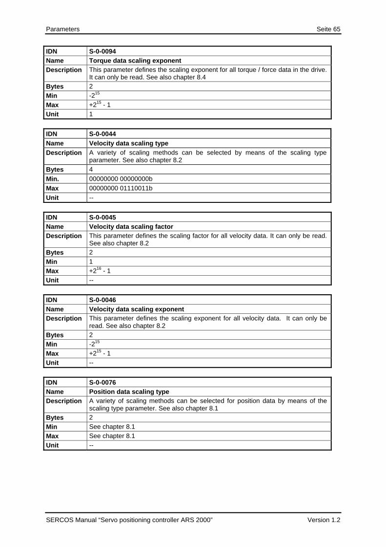
Parameters Seite 65
IDN S-0-0094 Name Torque data scaling exponent Description This parameter defines the scaling exponent for all torque / force data in the drive.
It can only be read. See also chapter 8.4Bytes 2 Min -215
Max +215 - 1 Unit 1 IDN S-0-0044Name Velocity data scaling type Description A variety of scaling methods can be selected by means of the scaling type
parameter. See also chapter 8.2Bytes 4 Min. 00000000 00000000b Max 00000000 01110011b Unit -- IDN S-0-0045 Name Velocity data scaling factor Description This parameter defines the scaling factor for all velocity data. It can only be read.
See also chapter 8.2Bytes 2 Min 1 Max +216 - 1 Unit -- IDN S-0-0046 Name Velocity data scaling exponent Description This parameter defines the scaling exponent for all velocity data. It can only be
read. See also chapter 8.2Bytes 2 Min -215
Max +215 - 1 Unit -- IDN S-0-0076 Name Position data scaling type Description A variety of scaling methods can be selected for position data by means of the
scaling type parameter. See also chapter 8.1Bytes 2 Min See chapter 8.1Max See chapter 8.1Unit --
SERCOS Manual “Servo positioning controller ARS 2000” Version 1.2

Seite 66 Parameters
IDN S-0-0077 Name Linear position data scaling factor Description This parameter defines the scaling factor for all position data in a drive. It can only
be read. See also chapter 8.1Bytes 2 Min 1 Max +216 - 1 Unit -- IDN S-0-0078 Name Linear position data scaling exponent Description This parameter defines the scaling exponent for all position data in a drive. It can
only be read. See also chapter 8.1Bytes 2 Min -215
Max +215 - 1 Unit --
IDN S-0-0079 Name Rotational position resolution Description This parameter defines the rotational position resolution for all position data in a
drive. It can only be read. See also chapter 8.1Bytes 4 Min 1 Max +232 – 1 Unit --
IDN S-0-0103 Name Modulo value Description If bit 7 (Modulo format) is set in IDN S-0-0076 the position data will be given within
the range 0…S-0-103. The maximum difference between two consecutive position command values must not exceed IDN S-0-0103 / 2 ! See also chapter 8.1
Bytes 4 Min 0 Max +231 – 1 Unit According to position data scaling type (IDN S-0-0076)
Version 1.2 SERCOS Manual ”Servo positioning controller ARS 2000”

Parameters Seite 67
IDN S-0-0160 Name Acceleration data scaling type Description A variety of scaling methods can be selected by means of the acceleration data
scaling type parameter. See chapter 8.3Bytes 2 Min See chapter 8.3Max See chapter 8.3Unit --
IDN S-0-0161 Name Acceleration data scaling factor Description This parameter defines the scaling factor for all acceleration data in a drive. It can
only be read. See chapter 8.3Bytes 2 Min 1 Max +216 – 1 Unit 1
IDN S-0-0162 Name Accelerations data scaling exponent Description This parameter defines the scaling exponent for all acceleration data in a drive. It
can only be read. See chapter 8.3Bytes 2 Min -215
Max +215 – 1 Unit 1
IDN S-0-0208 Name Temperature data scaling type Description This scaling type parameter determines whether degree Celsius [°C] or Fahrenheit
[F] is used as unit for all temperature data in the drive. The data length of temperature data is fixed to two bytes. See chapter 8.5
Bytes 2 Min 00000000 00000000b Max 00000000 00000001b Unit --
SERCOS Manual “Servo positioning controller ARS 2000” Version 1.2

Seite 68 Parameters
IDN S-0-0121 Name Input revolutions of load gear Description If a scaling type with reference to the load is selected, an gear is calculated within
the conversion factors. The input revolution values must be entered as integer value in this IDN.
Bytes 4 Min 1 Max +232 - 1 Unit 1
IDN S-0-0122 Name Output revolutions of load gear Description If a scaling type with reference to the load is selected, an gear is calculated within
the conversion factors. The output revolution values must be entered as integer value in this IDN.
Bytes 4 Min 1 Max +232 - 1 Unit 1
IDN S-0-0123 Name Feed constant Description The feed constant describes the machine element which converts a rotational
motion into a linear motion. The feed constant indicates the linear distance during one revolution of the feed spindle. It is used for all linear data scaling.
Bytes 4 Min 1 Max +232 - 1 Unit 1 µm / Revolution
Version 1.2 SERCOS Manual ”Servo positioning controller ARS 2000”

Parameters Seite 69
13.7 Command / Feedback values IDN Description
S-0-0047 Position command valueS-0-0051 Position feedback value 1S-0-0053 Position feedback value 2S-0-0036 Velocity command valueS-0-0040 Velocity feedback value 1S-0-0080 Torque command value S-0-0083 Torque feedback value 1
IDN S-0-0047 Name Position command value Description During the position control operation mode, the position command values are
transferred from the control unit to the drive according to the time pattern of the control unit cycle.
Bytes 4 Min -231
Max +231 - 1 Unit According to position data scaling type (IDN S-0-0076)
IDN S-0-0051 Name Position feedback value 1 (motor feedback) Description The position feedback value 1 is transferred from the drive to the control unit so
that it is possible for the control unit to monitor and display position information. The position feedback value 1 refers to the motor encoder (ServoCommander™: Operation mode / Encoder selection / Commutating Encoder) Important: If position control on feedback value 2 (external feedback) is selected
, the value of this IDN is 0. Bytes 4 Min -231
Max +231 – 1 Unit According to position data scaling type (IDN S-0-0076) Unit According to position data scaling type (IDN S-0-0076)
SERCOS Manual “Servo positioning controller ARS 2000” Version 1.2

Seite 70 Parameters
IDN S-0-0053 Name Position feedback value 2 (external feedback) Description Position feedback value 2 contains the position actual value of an optional external
encoder. (ServoCommander™: Operation mode / Encoder selection / Actual Position Value) Important: If position control on feedback value 1 (motor feedback) is selected as
operation mode, the value of this IDN is 0. Bytes 4 Min -231
Max +231 – 1 Unit According to position data scaling type (IDN S-0-0076)
IDN S-0-0036Name Velocity command value Description In the velocity control operation mode in the drive, the control unit transfers the
velocity command values to the drive in the time pattern of the control unit cycle time.
Bytes 4 Min. -- Max -- Unit According to actual velocity data scaling (S-0-0044)
IDN S-0-0040Name Velocity feedback value 1 Description The velocity feedback value 1 is transferred from the drive to the control unit in
order to allow the control unit to periodically display the velocity. The velocity feedback value 1 always refers to the motor encoder (ServoCommander™: Operation mode / Encoder selection / Commutating Encoder)
Bytes 4 Min. -- Max -- Unit According to actual velocity data scaling (S-0-0044)
IDN S-0-0080 Name Torque command value Description During the torque control operation mode of the drive, torque command values are
transferred from the control unit to the drive. Bytes 2 Min -215
Max +215 - 1 Unit According to torque data scaling type (IDN S-0-0086)
Version 1.2 SERCOS Manual ”Servo positioning controller ARS 2000”

Parameters Seite 71
IDN S-0-0084 Name Torque feedback value Description The torque feedback value is transferred from the drive to the control unit during
torque control operation mode. Bytes 2 Min -215
Max +215 – 1 Unit According to torque data scaling type (IDN S-0-0086)
SERCOS Manual “Servo positioning controller ARS 2000” Version 1.2

Seite 72 Parameters
13.8 Limitation / Monitoring IDN Description
S-0-0091 Bipolar velocity limit valueS-0-0092 Bipolar torque limit valueS-0-0049 Positive position limit valueS-0-0050 Negative position limit valueS-0-0114 Load limit of motor S-0-0057 Position window S-0-0125 Velocity threshold (nx) S-0-0157 Velocity window S-0-0124 Standstill window S-0-0159 Monitoring window S-0-0189 Following distance S-0-0200 Amplifier warning temperatureS-0-0201 Moto warning temperatureS-0-0206 Drive on delay S-0-0207 Drive off delay
IDN S-0-0091 Name Bipolar velocity limit value Description If the bipolar velocity limit value is exceeded, the drive responds by setting the status
“ncommand > nlimit” in C3D (see IDN S-0-0013). Bytes 4 Min 0 Max +231 - 1 Unit According to velocity data scaling type (IDN S-0-0044)
IDN S-0-0092 Name Bipolar torque limit value Description The torque setpoint is limited to this value in all operation modes except torque
control. Important: The status bit “T(orque) > Tlimit” in C3D (IDN S-0-0013) is not supported
yet. Bytes 2 Min 0 Max +215 - 1 Unit According to torque data scaling type (S-0-0086)
Version 1.2 SERCOS Manual ”Servo positioning controller ARS 2000”

Parameters Seite 73
IDN S-0-0049 Name Positive position limit value Description The positive position limit value describes the maximum allowed distance in the
positive direction. The positive position limit value is only enabled when all position data are based on the machine zero point. When the positive position limit value is exceeded, the drive sets an error bit in C1D (IDN S-0-0011). Important: The position limit value is only active in the operation mode “drive
controlled interpolation” Bytes 4 Min -231
Max +231 - 1 Unit According to position data scaling type (IDN S-0-0076)
IDN S-0-0050 Name Negative position limit value Description The negative position limit value describes the maximum allowed distance in the
negative direction. The negative position limit value is only enabled when all position data are based on the machine zero point. Important: The position limit value is only active in the operation mode “drive
controlled interpolation” Bytes 4 Min -231
Max +231 – 1 Unit According to position data scaling type (IDN S-0-0076)
IDN S-0-0114 Name Load limit of motor Description The motor can be overloaded a certain period of time. This IDN indicates how long
the motor may receive the maximum current. After this time the current will be automatically reduced to the nominal current to protect the motor. In this case the drive sets the overload warning bit in C2D (see IDN S-0-0310).
Bytes 2 Min 10 Max 2000 Unit ms
IDN S-0-0057 Name Position window Description When the difference between the accumulated position command value and the
position feedback value is within the range of the position window, then the drive sets the status “in position” (IDN S-0-0336). The status “in position” can be assigned to a realtime status bit (statusword) (see IDN S-0-0305).
Bytes 4 Min 0 Max +231 - 1 Unit According to position data scaling type (IDN S-0-0076)
SERCOS Manual “Servo positioning controller ARS 2000” Version 1.2

Seite 74 Parameters
IDN S-0-0125 Name Velocity threshold (nx) Description If the velocity feedback value falls below the velocity threshold nx , the drive sets the
status: “nfeedback < nx” (IDN S-0-0332) in C3D. Bytes 4 Min -231 - 1 Max +231 - 1 Unit According to velocity data scaling type (IDN S-0-0044)
IDN S-0-0157 Name Velocity window Description The velocity window relates the current velocity to the velocity command value (IDN
S-0-0036). If the current velocity feedback value falls within the window of the velocity command value plus or minus the velocity window, the drive sets the status: “nfeedback = ncommand” (IDN S-0-0330).
Bytes 4 Min 0 Max +231 - 1 Unit According to velocity data scaling type (IDN S-0-0044)
IDN S-0-0124 Name Standstill window Description The standstill window describes the amount of the deviation of the velocity from 0. If
the velocity feedback value is within the standstill window the drive sets the status: “nfeedback = 0” (IDN S-0-0331) in C3D.
Bytes 4 Min 0 Max +231 - 1 Unit According to velocity data scaling type (IDN S-0-0044)
IDN S-0-0159 Name Monitoring window Description By means of the monitoring window, the maximum position deviation, as referenced
to the active position feedback value, can be defined for the position feedback value. When the position error (following error) value exceeds the maximum value of the monitoring window, the drive sets an error for excessive position deviation in C1D (IDN S-0-0011).
Bytes 4 Min 0
Max +231 - 1 Unit According to position data scaling type (IDN S-0-0076)
Version 1.2 SERCOS Manual ”Servo positioning controller ARS 2000”

Parameters Seite 75
IDN S-0-0189 Name Following distance Description The drive uses the operation data of this IDN to store the distance between the
position command value and the appropriate position feedback value (1 or 2). following distance = position command value - position feedback value (1 or 2) S-0-0189 = S-0-0047 - S-0-0051 or S-0-0053
Bytes 4 Min -231 – 1 Max +231 – 1 Unit According to position data scaling type (S-0-0076)
IDN S-0-0200 Name Amplifier warning temperature Description When the amplifier temperature exceeds the amplifier warning temperature value, the
drive shutdown with an error (C1D). This IDN is read only. Bytes 2 Min -- Max -- Unit According to temperature data scaling type (S-0-0208)
IDN S-0-0201 Name Motor warning temperature Description When the motor temperature exceeds the motor warning temperature value, the drive
shutdown with an error (C1D). Bytes 2 Min 20 °C Max 300 °C Unit According to temperature data scaling type (S-0-0208)
IDN S-0-0206 Name Drive on delay time Description This IDN describes the time delay between the activation of torque via the bits "drive
on" and "drive enable" (bits 14 and 15) in the master controlword (S-0-0134) and the physical start of the movement. This delay is necessary if the connected motor uses a holding brake to release the brake before start of movement.
Bytes 2 Min 0 Max 5785,6 Unit ms
SERCOS Manual “Servo positioning controller ARS 2000” Version 1.2

Seite 76 Parameters
IDN S-0-0207Name Drive off delay time Description If the master resets the bit "drive off" (bit 15) of the master control word (S-0-0134),
the drive decelerates to nmin. Afterwards the locking of the holding brake is initiated. The torque remains activated in the drive until this drive off delay time is elapsed.
Bytes 2 Min 0 Max 5785,6 Unit ms
13.9 Signal statusword / Realtime bits IDN Description
S-0-0144 Signal statusword S-0-0026 Configuration list for signal statusword S-0-0300 Realtime control bit 1 S-0-0302 Realtime control bit 2 S-0-0301 Allocation of realtime control bit 1 S-0-0303 Allocation of realtime control bit 2
IDN S-0-0144 Name Signal statusword Description Signals can be transmitted in real-time from the drives to the control unit by means of
the signal statusword. For this purpose, the signal statusword needs to be integrated in the AT as cyclic data. Bits in the signal status word are definable by means of the configuration list of the signal status word (see IDN S-0-0026). Important: Only statusbits such as IDN S-0-0401 (Sample Input-1) are allowed to be
transmitted via the Signal statusword. The configuration of the signal statusword with certain bits of complex IDNs is not allowed.
Bytes 2 Min -- Max -- Unit --
Version 1.2 SERCOS Manual ”Servo positioning controller ARS 2000”

Parameters Seite 77
IDN S-0-0026Name Configuration list for signal statusword Description This is the configuration list for all status bits wich are shown in the signal status word
(S-0-0144). The sequence of the IDNs in the configuration list determines the bit numbering scheme in IDN S-0-0144, starting with the LSB in the signal status word. The initial IDN of the configuration list defines bit 0. The last IDN defines bit 15 of the signal status word. Important: Not all IDNs are allowed to be transmitted via the signal status word.
The configured IDNs must be status bits (e.g. IDN S-0-0401 – "sample input-1"). The configuration of IDN list S-0-0026 is checked every time writing it via the service channel. Invalid IDNs are deleted from the list.
Bytes IDN list Min. 0 IDNs Max 16 IDNs Unit IDN list
IDN S-0-0300 Name Realtime control bit 1 Description The value of the “realtime control bit 1” which is also transmitted via bit 6 of the
“master control word” (S-0-0134) can be accessed by this IDN. Bytes 2 Min 00000000 00000000b Max 00000000 00000001b Unit --
IDN S-0-0302 Name Realtime control bit 2 Description The value of the “realtime control bit 2” which is also transmitted via bit 7 of the
“master control word” (S-0-0134) can be accessed by this IDN. Bytes 2 Min 00000000 00000000b Max 00000000 00000001b Unit --
IDN S-0-0301
SERCOS Manual “Servo positioning controller ARS 2000” Version 1.2

Seite 78 Parameters
Name Allocation of realtime control bit 1 Description In order to assign a signal to the “realtime control bit 1” (S-0-0300) and bit 6 of the
“master controlword” (S-0-0134), the IDN of the signal is written to the operation data of S-0-0301. Only IDN S-0-0405 (probe 1 enable) is allowed to be configured as realtime control bit in S-0-0301. If the “realtime control bit 1” is not used, the value of IDN S-0-0301 should be set to “S-0-0000”. In this case the “realtime control bit 1” has no function.
Bytes 2 Min S-0-0000 (no signal defined) Max S-0-0405 Unit --
IDN S-0-0303 Name Allocation of realtime control bit 2 Description In order to assign a signal to the “realtime control bit 2” (S-0-0302) and bit 7 of the
“master controlword” (S-0-0134), the IDN of the signal is written to the operation data of S-0-0303. Only IDN S-0-0405 (probe 1 enable) is allowed to be configured as realtime control bit in S-0-0303. If the “realtime control bit 2” is not used, the value of IDN S-0-0303 should be set to “S-0-0000”. In this case the “realtime control bit 2” has no function.
Bytes 2 Min S-0-0000 (no signal defined) Max S-0-0405 Unit --
IDN S-0-0304 Name Realtime status bit 1 Description The value of the “realtime status bit 1” which is also transmitted via bit 6 of the “drive
statusword” (S-0-0135) can be read in this IDN. Bytes 2 Min -- Max -- Unit --
IDN S-0-0306 Name Realtime status bit 2 Description The value of the “realtime status bit 2” which is also transmitted via bit 7 of the “drive
statusword” (S-0-0135) can be read in this IDN. Bytes 2 Min -- Max -- Unit --
Version 1.2 SERCOS Manual ”Servo positioning controller ARS 2000”

Parameters Seite 79
IDN S-0-0305 Name Allocation of realtime status bit 1 Description In order to assign a signal to the “realtime status bit 1” (S-0-0304) and bit 6 of the
“drive statusword” (S-0-0135), the IDN of the signal is written to the operation data of S-0-0305. Not all IDNs are allowed to be transmitted as “realtime status bit”. A list of all configurable IDNs is given below.
Bytes 2 Min S-0-0000 (no signal defined) Max S-x-xxxx (see list) Unit --
IDN S-0-0307 Name Allocation of realtime status bit 2 Description In order to assign a signal to the “realtime status bit 2” (S-0-0306) and bit 7 of the
“drive status word” (S-0-0135), the IDN of the signal is written to the operation data of S-0-0307. Not all IDNs are allowed to be transmitted as “realtime status bit”. A list of all configurable IDNs is given below:
Bytes 2 Min S-0-0000 (no signal defined) Max S-x-xxxx (see list) Unit --
IDN Description IDN Description
S-0-0310 Overload warning S-0-0336 Status “In position” S-0-0311 Amplifier overtemperature warning S-0-0400 Home switch S-0-0312 Motor overtemperature warning S-0-0401 Probe 1 S-0-0330 Status “nfeedback = ncommand” S-0-0403 Position feedback value status S-0-0331 Status “nfeedback = 0” S-0-0409 Probe 1 positive latched S-0-0332 Status “nfeedback < nx” S-0-0410 Probe 1 negative latched
SERCOS Manual “Servo positioning controller ARS 2000” Version 1.2

Seite 80 Parameters
13.10 Statusbits IDN Description
S-0-0310 Signal statusword S-0-0311 Amplifier overtemperature warning (status) S-0-0312 Motor overtemperature warning (status) S-0-0330 Status “nfeedback = ncommand” S-0-0331 Status “nfeedback = 0” S-0-0332 Status “nfeedback < nx” S-0-0336 Status “In Position” S-0-0400 Home switch (status) S-0-0401 Probe1 S-0-0403 Position feedback value status S-0-0405 Probe 1 enable S-0-0409 Probe 1 positive latched S-0-0410 Probe 1 negative latched
IDN S-0-0310 Name Overload warning (status) Description This parameter is used to define an IDN for the “overload warning”. This allows the
“overload warning” to be assigned, for instance, to a realtime status bit (see IDN S-0-0305). The “overload warning” is also defined as a C2D bit (IDN S-0-0012) and is set appropriately according to the “overload limit value” (see IDN S-0-0114).
Bytes 2 Min -- Max -- Unit Statusbit (Bit 0)
IDN S-0-0311 Name Amplifier overtemperature warning (status) Description This parameter is used to define an IDN for the “amplifier overtemperature warning”.
This allows the “amplifier overtemperature warning” to be assigned, for instance, to a realtime status bit (see IDN S-0-0305). The “amplifier overtemperature warning” is also defined as a C2D bit (IDN S-0-0012) and is set appropriately according to the “amplifier warning temperature” (see IDN S-0-0200).
Bytes 2 Min -- Max -- Unit Statusbit (Bit 0)
Version 1.2 SERCOS Manual ”Servo positioning controller ARS 2000”

Parameters Seite 81
IDN S-0-0312 Name Motor overtemperature warning (status) Description This parameter is used to define an IDN for the “Motor overtemperature warning”. This
allows the “Motor overtemperature warning” to be assigned, for instance, to a realtime status bit (see IDN S-0-0305). The “Motor overtemperature warning” is also defined as a C2D bit (IDN S-0-0012) and is set appropriately according to the “Motor warning temperature” (see IDN S-0-0201).
Bytes 2 Min -- Max -- Unit Statusbit (Bit 0)
IDN S-0-0330 Name Status “nfeedback = ncommand” Description This parameter is used to define an IDN for the status “nfeedback = ncommand”.
This allows the status “nfeedback = ncommand” to be assigned to a realtime status bit (see IDN S-0-0305). The status “nfeedback = ncommand” is also defined as a C3D bit (IDN S-0-0013) and is set when the velocity feedback value (IDN S-0-0040) is within the programmed velocity window (IDN S-0-0157).
Bytes 2 Min -- Max -- Unit Statusbit (Bit 0)
IDN S-0-0331 Name Status “nfeedback = 0” Description This parameter is used to define an IDN for the status “nfeedback = 0”.
This allows the status “nfeedback = 0” to be assigned to a realtime status bit (see IDN S-0-0305). The status “nfeedback = 0” is also defined as a C3D bit (IDN S-0-0013) and is set when the velocity feedback value (IDN S-0-0040) lies within the programmed stansstill window (IDN S-0-0124).
Bytes 2 Min -- Max -- Unit Statusbit (Bit 0)
IDN S-0-0332 Name Status “nfeedback < nx” Description This parameter is used to define an IDN for the status “nfeedback < nx”.
This allows the status “nfeedback < nx” to be assigned to a realtime status bit (see IDN S-0-0305). The status “nfeedback < nx” is also defined as a C3D bit (IDN S-0-0013) and is set when the velocity feedback value (IDN S-0-0040) is smaller than the velocity threshold (S-0-0125).
Bytes 2 Min -- Max -- Unit Statusbit (Bit 0)
SERCOS Manual “Servo positioning controller ARS 2000” Version 1.2

Seite 82 Parameters
IDN S-0-0336 Name Status “In position” Description This parameter is used to define an IDN for the status “In position” to be assigned to a
realtime status bit (see IDN 305). The status “In position” is defined as a C3D bit (IDN S-0-0013) and is set when the position feedback value falls within the position window (see IDN S-0-0057) relative to the position command value. IMPORTANT: This bit is only evaluated in the drive in drive controlled operation
modes, such as “drive internal interpolation” or the “position spindle” procedure command (S-0-0152). It does not have a function in normal position control operation modes.
Bytes 2 Min -- Max -- Unit Statusbit (Bit 0)
IDN S-0-0400 Name Home switch (status) Description This parameter is used to assign an IDN to the home switch (external signal). This
allows the home switch to be allocated to a real-time status bit (see IDN S-0-0305). The home switch is an active high signal.
Bytes 2 Min -- Max -- Unit Statusbit (Bit 0)
IDN S-0-0401 Name Probe 1 Description This parameter is used to assign an IDN to Probe 1 (external signal). This allows
Probe 1 to be assigned to a real-time status bit (see IDN S-0-0305). Probe 1 is an active high signal. This IDN always displays the actual value of the sample switch, even if the “probing cycle” procedure command is not active in the drive.
Bytes 2 Min -- Max -- Unit Statusbit (Bit 0)
Version 1.2 SERCOS Manual ”Servo positioning controller ARS 2000”

Parameters Seite 83
IDN S-0-0403 Name Position feedback value status Description When the drive is referenced to the coordinates referred to the machine zero point, the
drive sets bit 0 of this parameter in order to inform the control unit that all actual position values are based on the zero point of the machine. Bit 0 is reset when either the procedure commands "drive controlled homing procedure" (IDN S-0-0148) or "cancel reference point" (IDN S-0-0191) are started or the drive loses its reference to the zero point of the machine e.g. due to an feedback system error. The position feedback value status can be assigned to a real-time status bit and therefore it can be permanently signalled to the control unit in the drive status word (see IDN S-0-0305).
Bytes 2 Min -- Max -- Unit Statusbit (Bit 0)
IDN S-0-0405 Name Probe 1 enable Description This parameter is used to assign an IDN to “Probe 1 enable”. This allows the bit
"Probe 1 enable" to be assigned to a real-time control bit (see IDN S-0-0301). “Probe 1 enable” is checked by the drive only as long as the procedure command "probing cycle" (IDN S-0-0170) is active. For a new probing cycle with the same edge of Probe 1 the control unit has to reset “Probe 1 enable” to "0" and set it to "1" again. See also chapter 12.3 and 0
Bytes 2 Min -- Max -- Unit Controlbit (Bit 0)
IDN S-0-0409 Name Probe 1 positive latched Description This parameter is used to assign an IDN to “Probe 1 positive latched”. This allows the
status "Probe 1 positive latched" to be assigned to a real-time status bit (see IDN S-0-0305). Bit 0 of this parameter is set by the drive only if the procedure command "probing cycle" (IDN S-0-0170) is active, the signal "probe 1 enable" (IDN S-0-0405) is set to 1 and the positive edge of "probe 1" (IDN 00401) is registered. Simultaneously the drive stores the position feedback value in "probe 1 positive edge" (IDN S-0-0130). This IDN will not be set to 0 by the drive, when the “probing cycle” procedure command is not active, but show the last value it had when the procedure command was still active. See also chapter 12.3.
Bytes 2 Min -- Max -- Unit Statusbit (Bit 0)
SERCOS Manual “Servo positioning controller ARS 2000” Version 1.2

Seite 84 Parameters
IDN S-0-0410Name Probe 1 negative latched Description This parameter is used to assign an IDN to “probe 1 negative latched”. This allows the
status "probe 1 negative latched" to be assigned to a realtime status bit (see IDN S-0-0305). Bit 0 of this parameter is set by the drive only if the procedure command "probing cycle" (IDN S-0-0170) is active, the signal "probe 1 enable" (IDN S-0-0405) is set to 1 and the negative edge of "probe 1" (IDN 00401) is registered. Simultaneously the drive stores the position feedback value in "probe 1 negative edge" (IDN S-0-0131). This IDN will not be set to 0 by the drive, when the “probing cycle” procedure command is not active, but show the last value it had when the procedure command was still active. See also chapter 12.3.
Bytes 2 Min -- Max -- Unit Statusbit (Bit 0)
13.11 Automatic identification
IDN Description
P-0-0101 Motoridentification current controller
P-0-0102 Motoridentification angle encoder
P-0-0103 Motoridentification status
IDN P-0-0101 Name Motoridentification current controller Description
All settings of the current controller can be determined automatically via this procedure command. Automatically detected settings are:
• Current controller gain • Current controller time constant
During the processing of P-0-0101 additional information can be read in P-0-0103. Note that the power stage has to be enabled (DIN4), but the controller has to be disabled (DIN5) for the proper execution of P-0-0101. Furthermore there must not be any errors in C1D and the motor must be able to turn without any load.
Bytes 2 Min. 0 Max Unit --
Version 1.2 SERCOS Manual ”Servo positioning controller ARS 2000”

Parameters Seite 85
IDN P-0-0102 Name Motoridentification angle encoder Description
All settings of the angle encoder can be determined automatically via this procedure command. Automatically detected settings are:
• Number of poles • Encoder offset angle • Phase sequence
During the processing of P-0-0102 additional information can be read in P-0-0103. Note that the power stage has to be enabled (DIN4), but the controller has to be disabled (DIN5) for the proper execution of P-0-0102. Furthermore there must be no errors in C1D and the motor must be able to turn without any load.
Bytes 2 Min. 0 Max Unit --
IDN P-0-0103Name Motoridentification status Description
Additional status information of the automatic motoridentification are displayed in this IDN. It should be read by the user, if any problem occurs while processing procedure commands P-0-0101 and P-0-0102. Note that even in case of the correct execution of P-0-0101 determined parameters could be limited or invalid. For this reason P-0-0103 should be evaluated by the user everytime P-0-0101 is executed. For further details see chapter 12.4
Bytes 4 Min. 0 Max Unit --
SERCOS Manual “Servo positioning controller ARS 2000” Version 1.2

Seite 86 Parameters
13.12 Error management
IDN P-0-0040Name Error_management: error_number Description
The IDN error_number contains the main error code, which reaction shall be changed. The main error code is normally displayed before the hyphen, e.g. error 08-2, main error code 8.
Bytes 4 Min. 0 Max 96 Unit
IDN P-0-0041Name Error_management: error_reaction Description
The reaction to the error can be changed with this IDN. If the manufacturer’s minimum reaction is lower then this reaction, it will be restricted to the minimum reaction. The actual adjusted reaction can be acquired via reading the IDN.
Bytes 4 Min. 0 Max 8 Unit
Value Meaning
0 No action
1 Entry in the buffer
3 Warning on the 7 segment display
5 Disable controller
7 Brake with maximum current
8 Disable power stage
Version 1.2 SERCOS Manual ”Servo positioning controller ARS 2000”

Parameters Seite 87
13.13 IO- Functions IDN Description
P-0-0110 Digital outputs P-0-0113 Function DOUT1 P-0-0114 Function DOUT2 P-0-0115 Function DOUT3 P-0-0125 Digital inputs
P-0-0126 Polarity of digital inputs
IDN P-0-0110 Name Digital outputs Description
Set digital outputs and read the status of the outputs. To allow writing an output, the function of the corresponding output must be set to 0.
Bytes 4 Min. 0 Max Unit --
Bit Description Value
0 DOUT0 Drive ready
1 DOUT1 0b: Off, 1b: On
2 DOUT2 0b: Off, 1b: On
3 DOUT3 0b: Off, 1b: On
4...31 Reserved IDN P-0-0113Name Function DOUT1 Description
Assign a status to the digital output or allow modification by IDN P-0-0110
Bytes 2 Min. 0 Max 16 Unit see Table
IDN P-0-0114Name Function DOUT2 Description
Assign a status to the digital output or allow modification by IDN P-0-0110
Bytes 2 Min. 0 Max 16 Unit see Table
SERCOS Manual “Servo positioning controller ARS 2000” Version 1.2

Seite 88 Parameters
IDN P-0-0115Name Function DOUT3 Description
Assign a status to the digital output or allow modification by IDN P-0-0110
Bytes 2 Min. 0 Max 16 Unit see Table
Value Description Value Description
0 Directly modify DOUT3 by P-0-0110 9 Undervoltage intermediate circuit
1 Position XSET = XDEST 10 Brake released
2 Position XACT = XDEST 11 Power stage released
3 Reserved 12 No function (ON)
4 Remaining distance trigger 13 Reserved
5 Homing operation active 14 Reserved
6 Target velocity reached 15 Linear motor identified
7 I²t-limit active 16 Homing position valid
8 Following error
Version 1.2 SERCOS Manual ”Servo positioning controller ARS 2000”

Parameters Seite 89
IDN P-0-0125 Name Digital intputs Description
The status of all digital inputs can be read via this IDN. As the polarity cannot be changed for most of them, the status of the DIN refers directly to the voltage level on the corresponding DIN.
Bytes 4 Min. 0 Max Unit --
Bit Name Description
0 DIN0 Set to “bit 0 of position selector” by default
1 DIN1 Set to “bit 1 of position selector” by default
2 DIN2 Set to “bit 2 of position selector” by default
3 DIN3 Set to “bit 3 of position selector” by default
4 DIN4 Power stage enable
5 DIN5 Controller enable
6 DIN6 Limit switch left (logical status)
7 DIN7 Limit switch right (logical status)
8 DIN8 Set to “start” by default (voltage level at DIN8)
9 DIN9 Set to “sample switch” by default (voltage level at DIN9)
10 DIN10 Double assignment with DOUT2
11 DIN11 Double assignment with DOUT3
12 DIN/AIN 1 Double assignment with AIN1
13 DIN/AIN 2 Double assignment with AIN2
14 Reserved Reserved
15 Reserved Reserved
16 EA88_0_0 DIN0 of optional EA88 module in TECH1
17 EA88_0_1 DIN1 of optional EA88 module in TECH1
18 EA88_0_2 DIN2 of optional EA88 module in TECH1
19 EA88_0_3 DIN3 of optional EA88 module in TECH1
20 EA88_0_4 DIN4 of optional EA88 module in TECH1
21 EA88_0_5 DIN5 of optional EA88 module in TECH1
22 EA88_0_6 DIN6 of optional EA88 module in TECH1
23 EA88_0_7 DIN7 of optional EA88 module in TECH1
24 Homing switch Logical status according to assignment of DIN and polarity
25 Sample switch Logical status according to assignment of DIN and polarity
26 Start Logical status according to assignment of DIN and polarity
27..31 Reserved Reserved
SERCOS Manual “Servo positioning controller ARS 2000” Version 1.2

Seite 90 Parameters
IDN P-0-0126 Name Polarity of digital intputs Description
The polarity of the digital inputs can be changed via this IDN. As only the limit switches and the sample switch can have an logical status other than the voltage level off the assigned DIN, only the polarity for this DINs can be changed. The Bit assignmemt is the same as in IDN P-0-0125.
Bytes 4 Min. 0 Max Unit --
13.14 Drive controlled homing IDN Description
S-0-0041 Homing velocity S-0-0042 Homing acceleration S-0-0147 Homing parameter S-0-0148 Drive controlled homing (procedure command)S-0-0150 Reference offset 1 S-0-0191 Cancel reference point (procedure command)P-0-0047 Homing method
IDN S-0-0041Name Homing velocity Description The homing velocity is used during the procedure command "drive controlled homing"
(IDN S-0-0148). Bytes 4 Min. -- Max -- Unit According to actual velocity data scaling (S-0-0044)
IDN S-0-0042Name Homing acceleration Description The homing acceleration is needed by the drive if the procedure command 'drive
controlled homing' (IDN S-0-0148) is activated. Bytes 4 Min. -- Max -- Unit According to actual velocity data scaling (S-0-0160)
Version 1.2 SERCOS Manual ”Servo positioning controller ARS 2000”

Parameters Seite 91
IDN S-0-0147 Name Homing parameter Description Several options for drive controlled homing can be set by this parameters. See also
chapter 12.1Bytes 2 Min 00000001 0001x100b Max 00000001 0001x10xb Unit --
IDN S-0-0148 Name Drive controlled homing (procedure command) Description By this procedure command drive controlled homing will be started. See also
chapter 12.1Bytes 2 Min -- Max -- Unit --
IDN S-0-0150 Name Reference offset 1 Description This parameter describes the distance between the reference marker pulse of
position feedback values and the reference point. In contrast to the SERCOS Specification there is no Reference offset for external feedback values. This IDN is used in both cases (internal and external position feedback evaluation) to define the reference offset for the drive controlled homing procedure command. See also chapter 12.1
Bytes 4 Min -231
Max +231 – 1 Unit According to position data scaling type (IDN S-0-0076)
IDN S-0-0191 Name Cancel reference point (procedure command) Description When the master sets and enables the procedure command "cancel reference point"
the drive resets the bit "position feedback value status" (IDN S-0-0403). The procedure command is completed successfully by the drive as soon as the bit "position feedback value status" is reset to 0.
Bytes 2 Min -- Max -- Unit --
SERCOS Manual “Servo positioning controller ARS 2000” Version 1.2

Seite 92 Parameters
IDN P-0-0045Name Homing method Description Manufacturer specific IDN, to determine the homing methods. See chapter 12.1Bytes 2 Min. Max Unit --
Version 1.2 SERCOS Manual ”Servo positioning controller ARS 2000”

Parameters Seite 93
13.15 Drive controlled interpolation IDN Description
S-0-0258 Target position S-0-0259 Positioning speed S-0-0260 Positioning acceleration S-0-0359 Positioning deceleration
IDN S-0-0258 Name Target position Description If “drive controlled interpolation” is selected as operation mode, this IDN is used by
the master to transmit the absolute target position. The drive moves to the target position, taking the “positioning velocity” (IDN S-0-0259), the “positioning acceleration” (IDN S-0-0260) and the “positioning deceleration” (IDN S-0-0359) into account.
Bytes 4 Min -231
Max +231 - 1 Unit according to position data scaling type (IDN S-0-0076)
IDN S-0-0259 Name Positioning speed Description The “positioning velocity” is used in the operation mode “drive controlled interpolation”
as the velocity for travelling to the “target position” (IDN S-0-0258). If the positioning acceleration (S-0-0260) or deceleration (S-0-0359) is set to a small value or the distance from the actual position feedback value (S-0-0051 or S-0-0053) to the target position (S-0-0258) is too short, the positioning speed may not be reached.
Bytes 4 Min -231
Max +231 – 1 Unit According to velocity data scaling type (IDN S-0-0044)
IDN S-0-0260 Name Positioning acceleration Description The “positioning acceleration” is used in the operation mode “drive controlled
interpolation” as the acceleration in all movements of the drive. Bytes 4 Min -231
Max +231 – 1 Unit According to acceleration data scaling type (IDN S-0-0160)
SERCOS Manual “Servo positioning controller ARS 2000” Version 1.2

Seite 94 Parameters
IDN S-0-0359Name Positioning deceleration Description The “positioning deceleration” is used in the operation mode “drive controlled
interpolation” as the deceleration in all movements of the drive. Bytes 4 Min -231
Max +231 – 1 Unit According to acceleration data scaling type (IDN S-0-0160)
13.16 Probing IDN Description
S-0-0130 Probe value 1 positive edgeS-0-0131 Probe value 1 negative edgeS-0-0169 Probe control parameterS-0-0170 Probing cycle procedure commandS-0-0179 Probe status
IDN S-0-0130 Name Probe value 1 positive edge Description If a positive edge of the sample input 1 occurs (IDN S-0-0401), the actual position
feedback value is stored in this IDN. If position control using position feedback value 1 is used as operation mode, the actual position feedback value 1 is stored in this IDN If position control using position feedback value 2 is used as operation mode, the actual position feedback value 2 is stored in this IDN This IDN is only supported, if the drive operates in an position control operation mode. See also chapter 12.3
Bytes 4 Min -231
Max +231 – 1 Unit According to position data scaling type (IDN S-0-0076)
Version 1.2 SERCOS Manual ”Servo positioning controller ARS 2000”

Parameters Seite 95
IDN S-0-0131 Name Probe value 1 negative edge Description If a positive edge of the sample input 1 occurs (IDN S-0-0402), the actual position
feedback value is stored in this IDN. If position control using position feedback value 1 is used as operation mode, the actual position feedback value 1 is stored in this IDN If position control using position feedback value 2 is used as operation mode, the actual position feedback value 2 is stored in this IDN This IDN is only supported, if the drive operates in an position control operation mode. See also chapter 12.3
Bytes 4 Min -231
Max +231 - 1 Unit According to position data scaling type (IDN S-0-0076)
IDN S-0-0169 Name Probe control parameter Description This parameter defines which probes and which edges are activated for the probing
cycle procedure command. See also chapter 12.3Bytes 2 Min 00000000 00000000b Max 00000000 000000xxb Unit --
IDN S-0-0170 Name Probing cycle procedure command Description When the master sets and enables the probing cycle procedure command, the drive
reacts on the following parameters: “probe 1 enable” (IDN S-0-0405), and “probe 1” (IDN S-0-0401) as programmed in the “probe control parameter” (IDN S-0-0169). While the procedure command is activated, the control unit can start multiple measurements. If the control unit does not want any more measurements, the control unit cancels the procedure command.
Bytes 2 Min -- Max -- Unit --
SERCOS Manual “Servo positioning controller ARS 2000” Version 1.2

Seite 96 Parameters
IDN S-0-0179 Name Probe status Description If the drive stores one or more measurement values while the procedure command
"probing cycle” (IDN S-0-0170) is activated, it simultaneously sets the assigned bit in the probe status. If “probe 1 enable” (IDN S-0-0405) is reset by the control unit, the drive resets bit 0 and bit 1 of probe status. If “probe 2 enable” (IDN S-0-0406) is reset by the control unit, the drive resets bit 2 and bit 3 of probe status. Important: In contrast to the SERCOS specification the bits in the probe status are
not reset when the edges are not activated in IDN S-0-0169 and sample events already have taken place.
Bytes 2 Min -- Max -- Unit --
Version 1.2 SERCOS Manual ”Servo positioning controller ARS 2000”

Parameters Seite 97
13.17 Spindle positioning IDN Description
S-0-0153 Spindle angle position S-0-0180 Spindle relative offset S-0-0154 Spindle positioning parameter S-0-0222 Spindle positioning speed S-0-0152 Position spindle (Procedure command)
IDN S-0-0153 Name Spindle angle position Description This parameter is the absolute spindle angle position relative to the reference point.
The parameter is enabled only in connection with the position spindle procedure command (see IDN S-0-0152).
Bytes 4 Min -231
Max +231 - 1 Unit According to position data scaling type (IDN S-0-0076) IDN S-0-0180 Name Spindle relative offset Description The parameter is enabled only in connection with the position spindle procedure
command (see IDN S-0-0152). The spindle relative offset is added to the absolute position value while being processed. This parameter is used to drive the spindle of a certain number of revolutions.
Bytes 4 Min -231
Max +231 - 1 Unit According to position data scaling type (IDN S-0-0076) IDN S-0-0154 Name Spindle positioning parameter Description This IDN defines the type of the positioning via the “position spindle” procedure
command. It can be distinguished between an absolute or relative positioning. Furthermore the rotation direction can be changed from positive to negative. See also chapter 12.2
Bytes 2 Min 00000000 00000000b Max 00000000 00000x0xb Unit --
SERCOS Manual “Servo positioning controller ARS 2000” Version 1.2

Seite 98 Parameters
IDN S-0-0222 Name Spindle positioning speed Description When the position spindle procedure command (see IDN S-0-0152) is activated in the
drive, the drive accelerates or decelerates to the spindle positioning speed, depending on the current speed and positions the drive at the absolute spindle position (S-0-0153) or relative to the actual position (S-0-0180) depending on the spindle positioning parameter (S-0-0154). All positioning via the procedure command S-0-0152 will be done with the spindle positioning speed (S-0-0222). If the procedure command S-0-0152 is cancelled, this IDN will not have any effect at all. Important: Changing the spindle positioning speed will not affect an actual positioning.
It will be used for the next positioning the first time. Bytes 4 Min 0 Max 231 – 1 Unit According to velocity data scaling type (S-0-0044) IDN S-0-0152 Name Position spindle (procedure command) Description This procedure command automatically switches the drive to internal position loop
control, below the spindle positioning speed (IDN S-0-0222). While this command is active, all changes to cyclic command values are ignored. Additionally, depending on the “Spindle position parameter” (IDN S-0-0154), the drive positions the spindle absolute to the programmed angle position (IDN S-0-0153) or rotates the spindle relative (incrementally) (IDN S-0-0180). When the drive interpolator reaches the selected command value, the drive sets the status ‘Target position attained’ (IDN S-0-0342). While this procedure command is active, the drive maintains the position control and adjusts to every new command value (IDN S-0-0153 or S-0-0180) which is transferred through the service channel. When the control unit cancels this command, the drive switches over to the mode of operation set in the control word. See also chapter 12.2
Bytes 2 Min -- Max -- Unit --
Version 1.2 SERCOS Manual ”Servo positioning controller ARS 2000”

Parameters Seite 99
13.18 Miscellanous IDN Description
S-0-0104 Position loop Kv factor S-0-0108 Feedrate override S-0-0265 Language designation
IDN S-0-0104 Name Position loop KV factor Description The gain of the position loop controller can be set by this IDN. Bytes 2 Min 0 Max 15 Unit 0,001 (meter/min)/millimeter
IDN S-0-0108 Name Feedrate override Description The feedrate override is activated only with drive controlled procedure commands. In
such a case, the velocity command value is calculated internally by the drive. The feedrate override has multiplying effects on the velocity command value.
Bytes 2 Min 0 Max 200 Unit 0,001 %
IDN P-0-0100 Name Torque constant Description The torque constant is needed to calculate all torque data which is transmitted in Nm
on the SERCOS bus into drive internal values in Ampere. Therefore the conversion factor in Nm/A can be entered in this IDN
Bytes 2 Min 0,01 Max 100,00 Unit Nm/A
IDN S-0-0265 Name Language designation Description The language, in which all ASCII strings will be transmitted to the master can be
selected via this IDN. Two languages can be selected. 0: German 1: English
Bytes 2 Min 0 Max 1 Unit --
SERCOS Manual “Servo positioning controller ARS 2000” Version 1.2

Seite 100 Parameters
IDN P-0-0020Name Drive enable status Description
To check, if the servo controller can be enabled by the controlword, it is possible to read out the ARS 2000 enable status before enabling the drive. If all bits in this IDN are 0 the drive is ready for drive enable. Otherwise the user is able to see, why the ARS 2000 can not be enabled.
Bytes 4 Min. 0 Max Unit --
Bit Description
0 Preload DC bus not completed
1 Encoder not ready
2 Autoidentification encoder still in progress
3 Autoidentification current controller still in progress
4…15 Reserved
16 Controller enable logic <> “DIn5 and SERCOS”
17 Logical powerstage enable is missing (according to enable logic: DIn4 + X )
18 Logical controller enable is missing (according to enable logic: DIn5 + X )
19 Reserved
20 Error existent
21 DIN4 missing
22 DIN5 missing
23…31 Reserved
Version 1.2 SERCOS Manual ”Servo positioning controller ARS 2000”

Parameters Seite 101
13.19 Informations IDN Description
S-0-0030 Manufacturer version S-0-0109 Motor peak current S-0-0110 Amplifier peak current S-0-0111 Motor continous current S-0-0112 Amplifier rated current S-0-0140 Spindle relative offset S-0-0141 Spindle positioning parameter S-0-0142 Application type S-0-0143 SERCOS interface version S-0-0096 Slave arrangement S-0-0134 Master controlword S-0-0135 Drive statusword
IDN S-0-0030Name Manufacturer version Description The version of the SERCOS implementation can be read by this IDN. Bytes -- Min. 01.00 Max 01.00 Unit Text
IDN S-0-0109Name Motor peak current Description The maximum current of the motor must be written to this IDN. The current of the
servo will be limited to this value. How long this value can be applied will be determined by S-0-0114.
Bytes 4 Min. -- Max -- Unit mA
IDN S-0-0110Name Amplifier peak current Description The maximum availabe current of the servo can be read by this IDN. Bytes 4 Min. -- Max -- Unit mA
SERCOS Manual “Servo positioning controller ARS 2000” Version 1.2

Seite 102 Parameters
IDN S-0-0111Name Motor continous current Description The nominal current of the motor must be written to this IDN. Bytes 4 Min. -- Max -- Unit mA
IDN S-0-0112Name Amplifier rated current Description The nominal current of the servo can be read by this IDN. Bytes 4 Min. -- Max -- Unit mA
IDN S-0-0140 Name Controller type Description The operation data of the controller type contains the name of the company and the
manufacturer controller type. Bytes variable with 1 byte length (ASCII) Min -- Max -- Unit --
IDN S-0-0141 Name Motor type Description This IDN may contain the name of the company and the manufacturer of the motor.
Up to now this IDN is not saved permanently in the ARS 2000. It is reset to an empty string every time switching power off.
Bytes variable with 1 byte length (ASCII) Min 0 ASCII chars Max 16 ASCII chars Unit --
IDN S-0-0142 Name Application type Description This IDN may contain the type of application. Up to now this IDN is not saved
permanently in the ARS 2000. It is reset to an empty string every time switching power off.
Bytes variable with 1 byte length (ASCII) Min 0 ASCII chars Max 16 ASCII chars Unit --
Version 1.2 SERCOS Manual ”Servo positioning controller ARS 2000”

Parameters Seite 103
IDN S-0-0143 Name SERCOS interface version Description This IDN shows the version number of the actual SERCOS Interface according to the
SERCOS specification V2.2 (November 2001) Bytes variable with 1 byte length (ASCII) Min -- Max -- Unit -- IDN S-0-0096 Name Slave arrangement Description During initialization, the master needs to recognize which physical slaves and their
associated drives are present in order to optimize the automatic timeslot computation. The master can request this information from the drives during CP2. By this entry the master recognizes other drives which belong to the same physical slave. Because ARS 2000 devices are slaves with one drive the Slave arrangement returns the drive address in the high and the low byte.
Bytes 2 Min -- Max -- Unit 1 IDN S-0-0134 Name Master controlword Description Enables the display of the master control word on the control unit screen, via the
service channel (This can be useful during start-up and error recovery). See also chapter 9
Bytes 2 Min -- Max -- Unit -- IDN S-0-0135 Name Drive statusword Description Enables the display of the drive status word on the control unit screen, via the service
channel (This can be useful during start-up and error recovery). See also chapter 9Bytes 2 Min -- Max -- Unit --
SERCOS Manual “Servo positioning controller ARS 2000” Version 1.2

Seite 104 Parameters
13.20 Diagnostic Classes
13.20.1 Class 1 diagnostic (C1D) IDN S-0-0011 Name Class 1 diagnostic Description This is the diagnostic class for all drive erros. Bytes 2 Min. -- Max -- Unit --
If an error situation of C1D occurs, the motor will be decelerated with the Quick stop deceleration (ServoCommander™: Parameters / Safety parameters). After decelerating the power stage will be switched off. Bit 13 of the drive statusword will be set to indicate the error situation.
C1D- Bits can only be reset by the command reset class 1 diagnostic (S-0-0099) if the cause of the error is not present anymore.
Bit Description ARS 2000 error nr.
See also
0 Overload 31 S-0-0114 1 Amplifier overtemperature 4 S-0-0203 2 Motor overtemperature 3 S-0-0204 3 -- - S-0-0205 4 Control voltage error 5 5 Feedback error 8 6 -- - 7 Overcurrent 6 8 Overvoltage 7 9 Undervoltage 2
10 -- - 11 Excessive position deviation 17 S-0-0159 12 Communication error - S-0-0014 13 Position limit exceeded 40 S-0-0049 14 -- 15 Manufacturer- specific error - S-0-0129
All errors that may occur in the ARS 2000 with no specific bit in the C1D will be set in S-0-0129 and therefore set bit 15 automatically.
Version 1.2 SERCOS Manual ”Servo positioning controller ARS 2000”

Parameters Seite 105
13.20.2 Manufacturer class 1 diagnostic IDN S-0-0129 Name Manufacturer class 1 diagnostic Description
If an error is set in the manufacturer class 1 diagnostic, the manufacturer-specific error bit in class 1 diagnostic (see IDN S-0-0011) is set as well. The drive cancels the manufacturer-specific error and resets to “0” only if the error in manufacturer class 1 diagnostic has been eliminated upon receiving the command “reset class 1 diagnostic” (see IDN S-0-0099) via the service channel. Structure of S-0-0129: Bit 0: Error in ARS 2000 0: No error 1: Error has occurred (see IDN S-0-0095 for Metronix error number) Bits 15 – 1 are reserved
Bytes 2 Min 00000000 00000000b Max 00000000 00000001b Unit -
Also Manufacturer class 1 diagnostics can only be reset by the command reset class 1 diagnostic (S-0-0099) if the cause of the error is not present anymore.
Bit Description ARS 2000 error nr.
0 General fault see S-0-0095 1 -- 2 -- 3 -- 4 -- 5 -- 6 -- 7 -- 8 -- 9 --
10 -- 11 -- 12 -- 13 -- 14 -- 15 --
SERCOS Manual “Servo positioning controller ARS 2000” Version 1.2

Seite 106 Parameters
13.20.3 IDN S-0-0095: Diagnostic Message IDN S-0-0095Name Diagnostic message Description The currently relevant operation status is being monitored with diagnostic messages.
The diagnostic messages are generated by the drive as a text and stored in the operation data of this IDN. If an error occurs in the drive, the actual Metronix error number is transmitted to the master via this IDN. For the error codes please refer to the Software Manual “Servo Positioning Controller ARS 2000”
Bytes variable with 1 byte length (ASCII) Min -- Max -- Unit --
13.20.4 Class 2 diagnostic (C2D) IDN S-0-0012Name Class 2 diagnostic Description
This is the diagnostic class for all Shut-down warnings (warning).
Bytes 2 Min. -- Max -- Unit --
In contrast to C1D the Class 2 Diagnostic reports warnings. C2D- Bits will be set, if the particular reason occurs and will be reset if the IDN will be read. Bit Nr. Description See also
0 Overload warning S-0-0310 1 Amplifier overtemperature warning S-0-0311 2 Motor overtemperature warning S-0-0312 3 -- 4 -- 5 -- 6 -- 7 -- 8 -- 9 --
10 -- 11 -- 12 -- 13 Target position out of travel range *) 14 -- 15 --
*) Only in “Drive controlled interpolation” operation mode
Version 1.2 SERCOS Manual ”Servo positioning controller ARS 2000”

Parameters Seite 107
13.20.5 Class 3 diagnostic (C3D) IDN S-0-0013Name Class 3 diagnostic Description This is the diagnostic class for all drive operation status flags. Bytes 2 Min. -- Max -- Unit --
Class 3 Diagnostic is composed out of status flags. C2D- Bits will be set, if the particular reason occurs and will be reset if the reason vanishes.
Bit Nr. Description See also 0 nfeedback = ncommand S-0-0330 1 nfeedback = 0 S-0-0331 2 nfeedback < nx S-0-0332 3 -- 4 -- 5 ncommand > nlimit S-0-0335 6 In position S-0-0336 7 -- 8 -- 9 --
10 -- 11 -- 12 -- 13 -- 14 -- 15 -- 15 Manufacturer- specific status S-0-0182
SERCOS Manual “Servo positioning controller ARS 2000” Version 1.2

Seite 108 Parameters
13.20.6 Manufacturer Class 3 diagnostic (C3D)
If an statusbit is set in the manufacturer class 3 diagnostic, the manufacturer-specific status bit in class 3 diagnostic (see IDN S-0-0013) is set as well. IDN S-0-0182Name Manufacturer Class 3 Diagnostic Description
Bytes 2 Min. Max Unit --
Bit Description
0 An internal automatic identification of the commutation position is necessary
1…15 Reserved
Version 1.2 SERCOS Manual ”Servo positioning controller ARS 2000”

Parameters Seite 109
13.20.7 IDN S-0-0014: „Interface Status“ IDN S-0-0014Name Interface status Description This is the diagnostic class for all communication errors.
A communication error in S-0-0014 leads to the following actions: a) A communication error is set in C1D (see IDN S-0-0011) if the interface
status is set by an error. b) If a communication error has occurred, the error and the CP at the time of
the error will be stored. The drive cancels a communication error and resets to '0' only if the error at the interface has been eliminated and on receiving the command 'reset class 1 diagnostic' (see IDN S-0-0099) via the service channel. The setting of bits 2–0 does not signify an error. If there are no communication errors present, the actual communication phase is contained in the interface status on these bits.
Bytes 2 Min. -- Max -- Unit -- The Interface status signals communication errors or protocol errors.
Bit Nr. Name Description ARS 2000 error nr.
0…2 Communication phase Actual phase -
3 MST error Two consecutive MSTs were missing. In CP3 or CP4 the ARS 2000 will fall back to Phase 0. An error occurs, the drive will be stopped.
37-2
4 MDT Fehler Two consecutive MDTs were missing. In CP4 the ARS 2000 will fall back to Phase 0. An error occurs, the drive will be stopped.
37-4
5 Invalid phase Invalid phase by the master (CP > 4) ARS 2000 will fall back to Phase 0. An error occurs, the drive will be stopped.
37-3
6 Error during phase upshift
Invalid phase sequence by the master. ARS 2000 will fall back to Phase 0. An error occurs, the drive will be stopped.
37-3
7 Error during phase downshift
Illegal value for downshift (not to phase 0). ARS 2000 will fall back to Phase 0. An error occurs, the drive will be stopped.
37-3
8 Phase switching without ready acknowledge
The master tries to change to CP3 or CP4 even though S-0-0127 or S-0-0128 haven’t been acknowledged correctly.
37-3
9 Switching to unitialised operation mode
An invalid or not initialised operation mode should be activated. An error occurs, the drive will be stopped.
37-5
10…15 Reserved
SERCOS Manual “Servo positioning controller ARS 2000” Version 1.2

Seite 110 Parameters
13.20.8 Diagnostics masks IDN S-0-0097 Name Mask class 2 diagnostic Description Using this mask, warnings in class 2 diagnostic can be masked with respect to their
effect on the change bit in drive status. When changing masked warnings, the change bit for class 2 diagnostic is not set in the drive status. The mask does not affect the operation data of class 2 diagnostic (see IDN S-0-0012).
Bytes 2 Min 00000000 00000000b Max 11111111 11111111b Unit - IDN S-0-0098 Name Mask class 3 diagnostic Description Using this mask, condition flags in C3D can be masked with respect to their effect on
the change bit in drive status. When masked condition flags change, the change bit for C3D is not set in the drive status. The mask does not affect the operation data of C3D (see IDN S-0-0013).
Bytes 2 Min 00000000 00000000b Max 11111111 11111111b Unit - IDN S-0-0099 Name Reset class 1 diagnostic (procedure command) Description When this procedure command is received by the drive via the service channel and
no error exists, C1D, the interface status, the manufacturer's C1D, the drive shut-down error (drive status bit 13), and the drive shut-down mechanism in the drive are all reset (see IDN S-0-0011, IDN S-0-0014, and IDN S-0-0129). See also chapter 13.20
Bytes 2 Min - Max - Unit -
Version 1.2 SERCOS Manual ”Servo positioning controller ARS 2000”

SERCOS error codes Seite 111
14 SERCOS error codes
The following errors using the SERCOS plug-in module may occur.
Code Name Description Action 37-0 Receive data
distortion The received data is over the distortion limit (INT_RDIST)
Test if fibre optic cable is connected correctly. Check baudrate.
37-1 Ring not closed The fibre optic ring seems not to be closed. (INT_FIBBR)
Test if fibre optic cable is connected correctly. Test if fibre optic cable is not broken. Check baudrate.
37-2 MST missing twice
Two consecutive MST were missing or have been received too late. In CP4 the ARS 2000 will fall back to Phase 0
Check baudrate. Test with higher baudrate. Test with higher cycle time
37-3 Invalid phase shift
The phase given in the MST is not allowed
See chapter 13.20.7
37-4 MDT missing twice
Two consecutive MDTs were missing. In CP4 the ARS 2000 will fall back to Phase 0.
Test if fibre optic cable is connected correctly. Check baudrate.
37-5 Invalid Operation mode
The selected Operation mode is invalid or not allowed.
Check S-0-0032, S-0-0033, S-0-0034 and S-0-0035. See also chapter 7
Code Name Description Action 38-0 Initialisation error Initialisation of SERCON
invalid Internal error
38-1 SERCOS active without plug-in module
The SERCOS communication is activated but it is no plug-in module available
Install plug-in module or deactivate SERCOS
38-2 Module failure The module selftest was not succesful
Change plug-in module
38-3 S-0-0127 failed While proceeding the Proce-dure command S-0-0127 not all parameters of S-0-0018 have been transmitted correctly.
Check IDN list S-0-0021 and re-execute the Procedure command
38-4 S-0-0127: Establishing MDT or AT failed
The cyclic data of the MDT or the AT could not be established.
Check S-0-0016 for the AT und S-0-0024 for the MDT. Check also S-0-0015
38-5 S-0-0128 failed While proceeding the Proce-dure command S-0-0128 not all parameters of S-0-00189 have been transmitted correctly.
Check IDN list S-0-0022 and re-execute the Procedure command
38-6 S-0-0128: Invalid scaling
Error during calculation of the desired scaling.
Check scaling and re-execute S-0-0128
38-7 IDN list S-0-0026 or IDN list S-0-0027 invalid
IDN list S-0-0026 or IDN list S-0-0027 contains an invalid (not allowed) IDN
Check S-0-0026 and S-0-0027
SERCOS Manual “Servo positioning controller ARS 2000” Version 1.2

Seite 112 SERCOS error codes
38-9 Invalid plug-in module
SERCON 816 in SERCON 410b compatibility mode
Internal error
Version 1.2 SERCOS Manual ”Servo positioning controller ARS 2000”

Appendix Seite 113
15 Appendix
To adjust the light power of the transmitting diodes different outputs can be activated together. The following chart gives an overview about the available levels and the corresponding outputs. The brightness increases with higher level numbers.
Level TXD1 TXD3 TXD4 TXD6
0 -- -- -- --1 ON -- -- --2 -- -- -- ON3 ON -- -- ON4 -- ON -- --5 ON ON -- --6 -- ON ON --7 -- ON -- ON8 ON ON -- ON9 ON ON ON --10 -- ON ON ON11 ON ON ON ON
Figure 15.2: Connection of transmitter diode
SERCOS Manual “Servo positioning controller ARS 2000” Version 1.2

Seite 114 Parameter index
16 Parameter index
16.1 By name Acceleration data scaling factor .............................66 Acceleration data scaling type ...............................66 Accelerations data scaling exponent ......................66 Allocation of realtime control bit 1........................77 Allocation of realtime control bit 2........................77 Allocation of realtime status bit 1 ..........................78 Allocation of realtime status bit 2 ..........................78 Amplifier overtemperature warning (status) ..........79 Amplifier peak current .........................................100 Amplifier rated current ........................................101 Amplifier warning temperature..............................74 Application type...................................................101 AT transmission starting time (t1) .........................54 Bipolar torque limit value ......................................71 Bipolar velocity limit value....................................71 Cancel reference point (procedure command) .......90 Class 1 diagnostic ................................................103 Class 2 diagnostic ................................................105 Class 3 diagnostic ................................................106 Command value proceeding time (tMTSG)...........56 Command value valid time (t3)..............................54 Communication cycle time (tScyc) ........................53 Configuration list AT.............................................57 Configuration list for signal statusword.................76 Configuration list of MDT .....................................57 Control unit cycle time (tNcyc)..............................53 Controller type .....................................................101 CP3 transition check (procedure command) ..........61 CP4 transition check (procedure command) ..........61 Diagnostic message..............................................105 Digital intputs.........................................................88 Digital outputs........................................................86 Drive controlled homing (procedure command)....90 Drive enable status.................................................99 Drive off delay time ...............................................75 Drive on delay time................................................74
Drive statusword ..................................................102 Error_management: error_number.........................85 Error_management: error_reaction ........................85 Feed constant .........................................................67 Feedback acquisition capture point (t4) .................54 Feedrate override ...................................................98 Following distance .................................................74 Function DOUT1 ...................................................86 Function DOUT2 ...................................................86 Function DOUT3 ...................................................87 Home switch (status)..............................................81 Homing acceleration ..............................................89 Homing method......................................................91 Homing parameter..................................................90 Homing velocity.....................................................89 IDN list of all configurable data in the AT ............58 IDN list of all configurable data in the MDT.........58 IDN list of all operation data..................................59 IDN list of all procedure commands ......................61 IDN list of invalid operation data for CP2 .............60 IDN list of invalid operation data for CP3 .............60 IDN list of invalid operation data for CP4 .............60 IDN list of operation data for CP2 .........................59 IDN list of operation data for CP3 .........................59 IDN list of operation data for CP4 .........................60 Input revolutions of load gear ................................67 Interface status .....................................................108 Language designation ............................................98 Length of configurable data record in the AT........58 Length of MDT ......................................................55 Length of the configurable data record in the MDT58 Linear position data scaling exponent....................65 Linear position data scaling factor .........................65 Load limit of motor ................................................72 Manufacturer class 1 diagnostic...........................104 Manufacturer Class 3 Diagnostic .........................107
Version 1.2 SERCOS Manual ”Servo positioning controller ARS 2000”

Parameter index Seite 115
Probing cycle procedure command........................94 Manufacturer version ...........................................100 Realtime control bit 1.............................................76 Mask class 2 diagnostic .......................................109 Realtime control bit 2.............................................76 Mask class 3 diagnostic .......................................109 Realtime status bit 1 ...............................................77 Master controlword..............................................102 Realtime status bit 2 ...............................................77 MDT error counter.................................................56 Receive to receive recovery time (tMTSY) ...........55 MDT transmission starting time (t2)......................56 Reference offset 1 ..................................................90 Minimum feedback processing time (t5) ...............54 Reset class 1 diagnostic (procedure command) ...109 Modulo value .........................................................65 Rotational position resolution ................................65 Monitoring window ...............................................73 Secondary operation mode 1..................................62 Motor continous current.......................................101 Secondary operation mode 2..................................62 Motor overtemperature warning (status)................80 Secondary operation mode 3..................................62 Motor peak current...............................................100 SERCOS interface version...................................102 Motor type............................................................101 Shortest AT transmission starting time (t1min) .....53 Motor warning temperature ...................................74 Signal statusword ...................................................75 Motoridentification angle encoder .........................84 Slave arrangement................................................102 Motoridentification current controller ...................83 Spindle angle position............................................96 Motoridentification status ......................................84 Spindle positioning parameter................................96 MST error counter .................................................56 Spindle positioning speed ......................................97 Negative position limit value .................................72 Spindle relative offset ............................................96 Output revolutions of load gear .............................67 Standstill window...................................................73 Overload warning (status)......................................79 Status “In position” ................................................81 Polarity of digital intputs .......................................89 Status “nfeedback < nx”.........................................80 Position command value ........................................68 Status “nfeedback = 0”...........................................80 Position data scaling type.......................................64 Status “nfeedback = ncommand” ...........................80 Position feedback value 1 (motor feedback)..........68 Target position .......................................................92 Position feedback value 2 (external feedback) ......69 Telegram type ........................................................57 Position feedback value status ...............................82 Temperature data scaling type ...............................66 Position loop KV factor .........................................98 Torque command value..........................................69 Position of data record in MDT .............................55 Torque constant......................................................98 Position spindle (procedure command)..................97 Torque data scaling exponent ................................64 Position window ....................................................72 Torque data scaling factor......................................63 Positioning acceleration .........................................92 Torque data scaling type ........................................63 Positioning deceleration.........................................93 Torque feedback value ...........................................70 Positioning speed ...................................................92 Transmit / Receive transition time (tATMT) .........53 Positive position limit value...................................72 Transmit to transmit recovery time (tATAT).........55 Primary operation mode.........................................62 Velocity command value........................................69 Probe 1 enable........................................................82 Velocity data scaling exponent ..............................64 Probe 1 negative latched ........................................83 Velocity data scaling factor....................................64 Probe 1 positive latched .........................................82 Velocity data scaling type ......................................64 Probe 1 ...................................................................81 Velocity feedback value 1......................................69 Probe control parameter .........................................94 Velocity threshold (nx) ..........................................73 Probe status ............................................................95 Velocity window....................................................73 Probe value 1 negative edge ..................................94 Probe value 1 positive edge ...................................93
SERCOS Manual “Servo positioning controller ARS 2000” Version 1.2

Seite 116 Parameter index
16.2 By IDN
P-0-0020 ................................................................98 P-0-0040 ................................................................84 P-0-0041 ................................................................84 P-0-0045 ................................................................90 P-0-0100 ................................................................97 P-0-0101 ................................................................82 P-0-0102 ................................................................83 P-0-0103 ................................................................83 P-0-0110 ................................................................85 P-0-0113 ................................................................85 P-0-0114 ................................................................85 P-0-0115 ................................................................86 P-0-0125 ................................................................87 P-0-0126 ................................................................88 S-0-0001 ................................................................53 S-0-0002 ................................................................53 S-0-0003 ................................................................53 S-0-0004 ................................................................53 S-0-0005 ................................................................54 S-0-0006 ................................................................54 S-0-0007 ................................................................54 S-0-0008 ................................................................54 S-0-0009 ................................................................55 S-0-0010 ................................................................55 S-0-0011 ..............................................................102 S-0-0012 ..............................................................104 S-0-0013 ..............................................................105 S-0-0014 ..............................................................107 S-0-0015 ................................................................57 S-0-0016 ................................................................57 S-0-0017 ................................................................59 S-0-0018 ................................................................59 S-0-0019 ................................................................59 S-0-0020 ................................................................60 S-0-0021 ................................................................60 S-0-0022 ................................................................60 S-0-0023 ................................................................60 S-0-0024 ................................................................57 S-0-0025 ................................................................61 S-0-0026 ................................................................75 S-0-0028 ................................................................56 S-0-0029 ................................................................56
S-0-0030.................................................................99 S-0-0032.................................................................62 S-0-0033.................................................................62 S-0-0034.................................................................62 S-0-0035.................................................................62 S-0-0036.................................................................69 S-0-0040.................................................................69 S-0-0041.................................................................88 S-0-0042.................................................................88 S-0-0044.................................................................64 S-0-0045.................................................................64 S-0-0046.................................................................64 S-0-0047.................................................................68 S-0-0049.................................................................71 S-0-0050.................................................................71 S-0-0051.................................................................68 S-0-0053.................................................................68 S-0-0057.................................................................71 S-0-0076.................................................................64 S-0-0077.................................................................65 S-0-0078.................................................................65 S-0-0079.................................................................65 S-0-0080.................................................................69 S-0-0084.................................................................69 S-0-0086.................................................................63 S-0-0087.................................................................55 S-0-0088.................................................................55 S-0-0089.................................................................56 S-0-0090.................................................................56 S-0-0091.................................................................70 S-0-0092.................................................................70 S-0-0093.................................................................63 S-0-0094.................................................................64 S-0-0095...............................................................104 S-0-0096...............................................................101 S-0-0097...............................................................108 S-0-0098...............................................................108 S-0-0099...............................................................108 S-0-0103.................................................................65 S-0-0104.................................................................97 S-0-0108.................................................................97 S-0-0109.................................................................99
Version 1.2 SERCOS Manual ”Servo positioning controller ARS 2000”

Parameter index Seite 117
S-0-0187.................................................................58 S-0-0110 ................................................................99 S-0-0188.................................................................58 S-0-0111 ..............................................................100 S-0-0189.................................................................73 S-0-0112 ..............................................................100 S-0-0191.................................................................89 S-0-0114 ................................................................71 S-0-0200.................................................................73 S-0-0121 ................................................................67 S-0-0201.................................................................73 S-0-0122 ................................................................67 S-0-0206.................................................................73 S-0-0123 ................................................................67 S-0-0207.................................................................74 S-0-0124 ................................................................72 S-0-0208.................................................................66 S-0-0125 ................................................................72 S-0-0222.................................................................96 S-0-0127 ................................................................61 S-0-0258.................................................................91 S-0-0128 ................................................................61 S-0-0259.................................................................91 S-0-0129 ..............................................................103 S-0-0260.................................................................91 S-0-0130 ................................................................92 S-0-0265.................................................................97 S-0-0131 ................................................................93 S-0-0300.................................................................75 S-0-0134 ..............................................................101 S-0-0301.................................................................75 S-0-0135 ..............................................................101 S-0-0302.................................................................75 S-0-0140 ..............................................................100 S-0-0303.................................................................76 S-0-0141 ..............................................................100 S-0-0304.................................................................76 S-0-0142 ..............................................................100 S-0-0305.................................................................77 S-0-0143 ..............................................................101 S-0-0306.................................................................76 S-0-0144 ................................................................74 S-0-0307.................................................................77 S-0-0147 ................................................................89 S-0-0310.................................................................78 S-0-0148 ................................................................89 S-0-0311.................................................................78 S-0-0150 ................................................................89 S-0-0312.................................................................79 S-0-0152 ................................................................96 S-0-0330.................................................................79 S-0-0153 ................................................................95 S-0-0331.................................................................79 S-0-0154 ................................................................95 S-0-0332.................................................................79 S-0-0157 ................................................................72 S-0-0336.................................................................80 S-0-0159 ................................................................72 S-0-0359.................................................................92 S-0-0160 ................................................................66 S-0-0400.................................................................80 S-0-0161 ................................................................66 S-0-0401.................................................................80 S-0-0162 ................................................................66 S-0-0403.................................................................81 S-0-0169 ................................................................93 S-0-0405.................................................................81 S-0-0170 ................................................................93 S-0-0409.................................................................81 S-0-0179 ................................................................94 S-0-0410.................................................................82 S-0-0180 ................................................................95
S-0-0182 ..............................................................106 S-0-0185 ................................................................58 S-0-0186 ................................................................58
SERCOS Manual “Servo positioning controller ARS 2000” Version 1.2