Embed Size (px)
Citation preview
CUSTOM END-OF-LINE INSPECTION SYSTEMS
P.NO. 5101-0020
S E N T R Y X R ( X - R AY )
C O N T A M I N A N T A N D PA C K F I L L
D E T E C T I O N S Y S T E M
USER MANUAL

SENTRY XR USER MANUAL V10
CUSTOM END-OF-LINE INSPECTION SYSTEMS
PAGE 2 OF 66
TABLE OF CONTENTS
CONTENTS PAGE1. INTRODUCTION ..........................................................................................................................8
1.1 METAL DETECTORS AND X-RAY SYSTEMS ................................................................8
2. SYSTEM COMPONENTS ............................................................................................................9
2.1 X-RAY SET .............................................................................................................................92.2 DETECTOR ..........................................................................................................................112.3 COMPUTER .........................................................................................................................12
3 STARTUP AND USING THE SYSTEM....................................................................................13
3.1 SELECTING OR CREATING A PRODUCT FOR INSPECTION..................................143.1.1 Deleting a Menu .............................................................................................................153.1.2 Deleting a Menu .............................................................................................................153.1.3 Copying a Menu..............................................................................................................163.1.4 Creating a New Menu.....................................................................................................16
3.2 STARTING INSPECTION...................................................................................................163.3 RUN MODE SCREEN .........................................................................................................18
3.3.1 SCREEN SELECTION....................................................................................................193.3.2 PRODUCT TRACE.........................................................................................................193.3.3 REJECT GRAPHIC ........................................................................................................21
4 MANUAL SYSTEM SETUP AND MENU STRUCTURE.......................................................22
4.1 MENU SETTINGS ...............................................................................................................224.1.1 Product Settings..............................................................................................................234.1.2 Pack Fill Detect Settings ................................................................................................284.1.3 Size Inspection Settings...................................................................................................324.1.4 Reject Settings.................................................................................................................334.1.5 System Settings ...............................................................................................................354.1.6 Security (Passwords) ......................................................................................................354.1.7 Lost Or Forgotten Passwords.........................................................................................364.1.8 Time & Date ...................................................................................................................374.1.9 Machine Logo .................................................................................................................374.1.10 Stats Archive Hour..........................................................................................................374.1.11 Language ........................................................................................................................384.1.12 Machine Id......................................................................................................................384.1.13 MIACS ............................................................................................................................384.1.14 MIACS ADDRESS ..........................................................................................................384.1.15 Line Number ...................................................................................................................394.1.13 Service Settings....................................................................................................................394.1.14 Statistics............................................................................................................................... 394.1.16 Diagnostics .....................................................................................................................404.1.17 Test Settings....................................................................................................................40
5 AUTOMATIC LEARNING AND PRODUCT TESTS.............................................................43
5.1 LEARNING – AN OVERVIEW ...........................................................................................435.1.1 FULL Learn....................................................................................................................445.1.2 REFRESH Learn.............................................................................................................44
5.2 PERFORMING A FULL LEARN ........................................................................................445.3 PERFORMING A REFRESH LEARN ...............................................................................475.4 SETTING THE REJECT TIMING .....................................................................................48

SENTRY XR USER MANUAL V10
CUSTOM END-OF-LINE INSPECTION SYSTEMS
PAGE 3 OF 66
5.5. PRODUCT TESTS ..............................................................................................................49
6. PERIPHERAL DEVICES ...........................................................................................................54
6.1 SERIAL PRINTER.....................................................................................................................546.2 SERIAL BARCODE SCANNER.........................................................................................556.3 MIACS (MANAGEMENT INFORMATION AND CONTROL SYSTEM) .......................55
7. BACKING UP VITAL SYSTEM DATA AND MENUS...........................................................56
8. TROUBLESHOOTING AND SERVICING..............................................................................57
8.1 SERVICE PROMPT ..................................................................................................................578.2 BASIC FAULT FINDING ..........................................................................................................58
9. CE AND SAFETY COMPLIANCE............................................................................................62
10. BASIC SPECIFICATION .......................................................................................................63
11. COMMONLY USED PARAMETERS GLOSSARY............................................................64
12. MENU LAYOUT......................................................................................................................66

SENTRY XR USER MANUAL V10
CUSTOM END-OF-LINE INSPECTION SYSTEMS
PAGE 4 OF 66
TABLE OF FIGURES
FIGURE PAGE
FIGURE 1.1 – X-RAY TUBE AND BEAM .........................................................................................9FIGURE 1.2 – DETECTOR, PRODUCT AND BEAMPATH..........................................................11FIGURE 3.1 – IDLE SCREEN ...........................................................................................................13FIGURE 3.2 – MENUS SCREEN (COPY, DELETE, RECALL)....................................................14FIGURE 3.3 – MENUS SCREEN (NEW MENU) ............................................................................15FIGURE 3.4 – STARTUP SCREEN..................................................................................................17FIGURE 3.5 - RUN MODE SCREEN................................................................................................18FIGURE 3.6 – PRODUCT TRACE SCREEN ..................................................................................20FIGURE 3.7 – REJECT GRAPHIC SCREEN..................................................................................21FIGURE 4.1 – GOTO MENU .............................................................................................................23FIGURE 4.2 – PRODUCT NAME SCREEN ....................................................................................24FIGURE 4.3 – VOLUME MEASUREMENT SCREEN....................................................................29FIGURE 4.4 – AREA MEASUREMENT SCREEN .........................................................................31FIGURE 4.5 – REJECT SETTINGS SCREEN ................................................................................33FIGURE 4.6 – SYSTEM SETTINGS SCREEN ...............................................................................35FIGURE 4.7 – TIME & DATE SCREEN ...........................................................................................37FIGURE 4.8 – STATISTICS SCREEN .............................................................................................39FIGURE 4.9 – TEST SETTINGS SCREEN .....................................................................................41FIGURE 5.1 – SELECTION OF LEARN FUNCTION....................................................................44FIGURE 5.2 – LEARN OPTION SCREEN.......................................................................................45FIGURE 5.3 – XRAY POWER WAITING FOR PACK SCREEN ..................................................46FIGURE 5.4 – XRAY POWER CALCULATION SCREEN ............................................................46FIGURE 5.5 – LEARN FAIL SCREEN..............................................................................................48FIGURE 5.6 – TEST DUE INDICATION ..........................................................................................50FIGURE 5.7 – TEST SELECTION SCREEN...................................................................................51FIGURE 5.8 – TEST SUBMISSION SCREEN ................................................................................52FIGURE 5.9 – TEST FAIL SCREEN.................................................................................................53FIGURE 8.1 – SERVICE INDICATOR .............................................................................................57

SENTRY XR USER MANUAL V10
CUSTOM END-OF-LINE INSPECTION SYSTEMS
PAGE 5 OF 66
SENTRY XR
CONTAMINANT AND PACK FILL DETECTION SYSTEM
USER MANUAL
REVI SION 1.2 JULY 2003
COPYRIGHT © 2003 THE CI NTEX G ROUP
ALL RIG HTS RESERVED
N O P A R T O F T H I S P U B L I C A T I O N M A Y B E R E P R O D U C E D , S T O R E D O N A
R E T R I E V A L S Y S T E M , O R T R A N S M I T T E D I N A N Y F O R M W I T H O U T T H E P R I O R
P E R M I S S I O N O F T H E C I N T E X G R O U P


SENTRY XR USER MANUAL V10
CUSTOM END-OF-LINE INSPECTION SYSTEMS
PAGE 7 OF 66
S AFETY NOTICE
Only qualified personnel should remove system panels.Accessing system internals will expose high voltage terminals and
potential Radiation Hazards.
This equipment has been designed for installation into a production lineand use for any means other than contaminant detection and fill
inspection is not authorised.
Operate the machine only in accordance with this manual.
NEVER TAMPER WITH OR DEFEAT INTERLOCK SYSTEMS
COMPLI ANCE NOTICE
The equipment has been designed to be part of an “INSTALLATION” asdefined by the current European Directives. The operation of any rejectmechanism controlled by this equipment may be hazardous; it may operatewithout warning. Its design & implementation must be carried out bycompetent personnel in accordance with local health & safety regulations andappropriate “installation” documentation maintained. It contains hazardousvoltages which must be treated in accordance with this handbook.
Note: “CINTEX Limited” is referred to several times in this handbook.This should be taken to include this company’s associate companies &agents.
CINTEX LimitedFeatherstone Road
Wolverton MillMilton Keynes MK12 5TH
England
Tel No: +44 (0) 1908 629200Fax No: +44 (0) 1908 579824

SENTRY XR USER MANUAL V10
CUSTOM END-OF-LINE INSPECTION SYSTEMS
PAGE 8 OF 66
1. INTRODUCTION
CINTEX Sentry XR Contaminant Detection Systems are designed to detectmetal and non-metallic contaminants in a wide range of products. They can, inaddition, also perform checks to ensure that contents are present in thepackage.
1.1 METAL DETECTORS AND X-RAY SYSTEMS
CINTEX Sentry XR Contaminant Detection Systems are designed to detectmetal and non-metallic contaminants in a wide range of products. They can, inaddition, also perform simple checks to ensure that contents are present inthe package.
Traditional Metal Detectors have their primary limitation in their name – theycan only find metals. The detection capability of a metal detector variesaccording to the product it is used on. Metal detectors perform best on dryproducts in non metallic packaging. However, when ‘wet’, frozen products, ormetallised / foil packaging is present, sensitivity can suffer. A primary concernon metal detectors is the conductivity of the product due to ‘wetness’ or saltcontent. These factors will cause false rejects, or a large drop in sensitivity.
A Metal Detector copes with conductivity by employing both a Threshold andPhase detection system. A ‘phase window’ is used which is effectively an areaof the product signal that is ignored in the detection process. The ‘wet’ orconductive parts of the signal are thereby excluded. HOWEVER, stainlesssteel detection can be considerably reduced by this technique, and may makethe Metal Detection system blind to certain grades of stainless steel.
A worst case for a Metal Detector system is when aluminium or foil trays arepresent. A special type of system, called a Ferrous In Foil detector, must beused. These have a limitation – they find only magnetic materials, makingthem completely blind to ALL stainless steels – most food lines are made ofstainless steel!
How do we overcome the limitations of only being able to find metal,(sometimes only certain grades of stainless), and improve sensitivity ondifficult frozen or wet products? Use X-ray based technology.
Traditionally, X-ray systems have been many more times the cost of a MetalDetector system. This is due to the high cost of the technology employed, highparts count, and lower production volumes.
Sentry XR is the first food inspection X-ray system to overcome these issues.By targeting packaged products of approx 500 x 260 x 75mm (L x W x H max)

SENTRY XR USER MANUAL V10
CUSTOM END-OF-LINE INSPECTION SYSTEMS
PAGE 9 OF 66
in dimension, and then optimising and simplifying the technology to suit thissize envelope, price barriers have come down.
2. SYSTEM COMPONENTS
An X-ray system consists of three basic components :
• X-ray Set• Detector• Computer
This section provides a basic description of what is inside the system andit’s internal operation, in order to create a greater understanding of how touse the machine.
2.1 X-RAY SET
FIGURE 1.1 – X-RAY TUBE AND BEAM

SENTRY XR USER MANUAL V10
CUSTOM END-OF-LINE INSPECTION SYSTEMS
PAGE 10 OF 66
The X-ray Set provides a ‘fan shaped’ beam of X-rays, that start from a1.5mm ‘spot’ and fan out, in a 1 - 2mm wide beam, to ‘illuminate’ the width ofthe conveyor belt. This means that the product only passes through a narrow‘waterfall’ of x-rays and receives minimal radiation at any given point for just afraction of a second. The amount of time taken to inspect a ‘slice’ of product istypically less than 1/500th of a second.
The 1mm wide narrow beam is similar to those employed in luggageinspection at airports, such that very low levels of X-rays are present at anygiven point of the product at any one time. In the same way that baggagesystems eliminates fogging of photographic film, the amount of x-rays passingthrough the food are made microscopically small.
An X-ray set is essentially a high voltage power supply, connected to an X-raytube. The tube is a thermionic device, similar to a radio valve (tube).
A high voltage across the tube, combined with a heating effect at the cathodeside of the tube, causes a stream of electrons to cross the tube at near lightspeed. When they impact upon the tungsten anode, they cause an emissionof radiation particles. If the high voltage is removed, by stopping the machineor opening a safety interlock, the tube is made immediately safe with NOresidual radiation. The radiation particles emitted are collimated bymechanical means into a 1mm beam which is then directed at the product.
The tube employed provides a wide 50 degree beam of x-rays which enablesthe source to be moved closer to the product, providing greater effective X-raypower.
The tube itself is mounted in a tank of cooling / insulating oil. Traditional X-raysystems have bulky pump / radiator based cooling systems to circulate andcool the oil – similar in principle to those used to water cool car engines.Sentry XR uses electronic solid state cooling devices to form a compact, onepiece X-ray source without pipes, pumps or radiators.
The combination of wide angle X-rays and an integral cooler is termed WASC– Wide Angle, Self Cooled.

SENTRY XR USER MANUAL V10
CUSTOM END-OF-LINE INSPECTION SYSTEMS
PAGE 11 OF 66
2.2 DETECTOR
X-rays are invisible. In order to detect or ‘see’ them, they need to beconverted electronically. This function is performed by the linear detector,which is mounted within the conveyor belt assembly.
A slot is formed into the top of the detector which allows the 1mm wide X-raybeam, which has passed though the product, to enter it. A few millimetresbelow the slot is a phosphor coating that when struck by X-rays, glows tocreate light. The intensity of the light is dependent on the X-ray signal whichis variable, depending upon the density of the product. More dense areas,such as those containing dense contamination, will create less light. This isthe essence of how contamination is detected.
FIGURE 1.2 – DETECTOR, PRODUCT AND BEAMPATH
The phosphor is mounted directly onto a line of diodes, which typically number384, each of which are 0.8mm square. The line of diodes are scannedelectronically, several hundred times a second. An electronic ‘picture’ is madeup of the product passing though the beam, formed of many horizontal lines.

SENTRY XR USER MANUAL V10
CUSTOM END-OF-LINE INSPECTION SYSTEMS
PAGE 12 OF 66
A similar approach can be seen in a fax machine – it pulls the paper through astep at a time, reading individual ‘lines’ of data, which are then sent over thephone line.
In Sentry XR, the scanning process provides horizontal information, where themovement of the conveyor ‘advances’ the product vertically to provide thesecond dimension.
The lines of scanned data, from the X-ray beam having passed through theproduct, are then passed to the system computer.
Sentry contains a patented method of ensuring that the detector maintainsstable reliable operation. IDC (Intelligent Detector Compensation) ensuresthat the system can function for many days between start up calibrations,where other systems may require recalibration several times a day.
2.3 COMPUTER
The computer system fitted to the Sentry XR is contained within the frontpanel / LCD assembly, and is identical to those fitted to standard Sentry MetalDetectors. It contains a different software program to allow it to function as anX-ray based detector.
Connections are present to control the X-ray source and to receive data fromthe linear detector system. The incoming data is buffered and processed toallow the system to make a decision on the integrity of the product.
Separate outputs are provided for both contamination and pack fill rejects,such that incomplete packs may be segregated from potentially contaminateditems.
When a defect is detected, the control microprocessor tracks the package asit moves out of the detector head towards the rejection device and operatesthe reject device at the right time. The microprocessor also carries out“housekeeping” tasks such as monitoring all key areas of the detector andreject device, and warning of a malfunction, running the alpha-numeric displayand, if required, reporting detection activity to a central computer.
The Operator Control Panel comprises a graphics LCD with a touch sensitivescreen. The software will show available choices along the bottom and righthand side of the screen. Pressing these areas will select the displayed item orfunction.

SENTRY XR USER MANUAL V10
CUSTOM END-OF-LINE INSPECTION SYSTEMS
PAGE 13 OF 66
3 STARTUP AND USING THE SYSTEM
Once power is applied to the system , the Sentry XR will go through a seriesof self tests.
During the system initialisation, the computer displays software version, andchecks internal memory. It then goes on to check that the detector and X-rayset are present and functional. Any faults will be displayed during theinitialisation phase.
On completion of the start up checks, the ‘Idle’ screen will be displayed, asshown below.
FIGURE 3.1 – IDLE SCREEN
If there was a problem detected during initialisation, the fault message will bedisplayed in the status bar at the top of the screen. If the screen shows a fault,it is advisable to power the system down, then up again, which may clear theproblem.
Check that there are no faults are indicated in the top status bar.

SENTRY XR USER MANUAL V10
CUSTOM END-OF-LINE INSPECTION SYSTEMS
PAGE 14 OF 66
3.1 SELECTING OR CREATING A PRODUCT FOR INSPECTION
Before the system can begin inspection, it is necessary to select a productfrom the available menus and press the START button. If the product is new,and never been previously set up, it is possible to create a new menu for theproduct.
Product selection and creation is available by pressing the Menus button atthe lower right side of the LCD screen.
FIGURE 3.2 – MENUS SCREEN (COPY, DELETE, RECALL)
From the ‘Menus’ screen there are several options. These are:
• Copy a menu. (Copies from an existing menu to an empty position).• Delete a menu.• Recall a menu. (Loads a product from menu for inspection) – This is the
one we need to begin inspection – unless its already the current product.• Create a New menu.
Note that the option to create a new menu only appears on the screen whenscrolling to an empty position.

SENTRY XR USER MANUAL V10
CUSTOM END-OF-LINE INSPECTION SYSTEMS
PAGE 15 OF 66
FIGURE 3.3 – MENUS SCREEN (NEW MENU)
3.1.1 Deleting a Menu
From the main ‘Run Mode’ screen, in order to recall a specific product menu,do as follows:
(Menus →→→→ (Use Up / Down To Select Menu) →→→→ Recall →→→→ Yes)
The system will now be set to the desired menu. Note that a menu may onlybe recalled if it has a name.
3.1.2 Deleting a MenuFrom the main ’Run Mode’ screen, in order to delete a specific menu, do asfollows:
(Menus →→→→ (Use Up / Down To Select Menu) →→→→ Delete →→→→ Yes)
The current highlighted menu will now be deleted. The menu positions willautomatically arrange themselves back in alphabetical order.

SENTRY XR USER MANUAL V10
CUSTOM END-OF-LINE INSPECTION SYSTEMS
PAGE 16 OF 66
3.1.3 Copying a MenuFrom the main ’Run Mode’ screen, in order to copy a specific menu, do asfollows:
(Menus →→→→ (Use Up / Down To Select Menu) →→→→ Copy →→→→ Yes)
The current highlighted menu will now be copied to an empty position,however the menu will still require a name. The menu positions willautomatically arrange themselves back in alphabetical order.
3.1.4 Creating a New MenuFrom the main ’Run Mode’ screen, in order to copy a specific menu, do asfollows:
(Menus →→→→ (Use Up / Down To Select empty position) →→→→ New →→→→ Yes)
A new menu will now be created with the same settings as the current runningmenu (the ‘Advanced settings’ are loaded from the ‘Service Settings’). Themenu positions will automatically arrange themselves back in alphabeticalorder.
3.2 STARTING INSPECTION
Once a product has been loaded or newly created, it is possible to start theinspection process.
Having selected the menu required, press the START button.
Before inspection can begin, it may be necessary to calibrate the system. Thedetector must be calibrated so that the performance of all 384 diodes remainsconstant and linear through the x-ray signal range. If Sentry XR decides acalibration is necessary, which will be when a new product is created, certainsettings have been altered, or 28 days have elapsed since the last calibration,it will perform one automatically.
During this time no product should pass through the system. At this stage, thesystem is not inspecting, so there should be no product passing as a matter ofcourse.

SENTRY XR USER MANUAL V10
CUSTOM END-OF-LINE INSPECTION SYSTEMS
PAGE 17 OF 66
FIGURE 3.4 – STARTUP SCREEN
The system will either perform an automatic calibration, or will display ascreen allowing you to recalibrate if you decide to do so. The option of amanual recalibration will elapse after THREE seconds.
If a calibration is performed, the system will go through a sequence, savingthe calibration into memory once complete. If the machine is powered down,or another product is selected, the calibration will remain valid for up to 28days.
Once calibration or start up is complete, the machine will begin inspectingproduct, based upon the previously learnt settings from the selected menu.Any products found to have defects will be automatically rejected andrecorded in the statistical details.
During inspection, a number of screens are available to show operationalstatus and aid understanding of the inspection process. When the machinefirst begins inspecting, the main Run Mode screen is shown.

SENTRY XR USER MANUAL V10
CUSTOM END-OF-LINE INSPECTION SYSTEMS
PAGE 18 OF 66
FIGURE 3.5 - RUN MODE SCREEN
3.3 RUN MODE SCREEN
Once inspection begins, the following items will be displayed
IINSPECTION METHODS This panel shows the inspection methods currently being employed in theinspection process, and any associated primary settings
PRODUCT TRACE PREVIEWSmall graphic representing the average threshold of the last product throughthe machine. (See Product Trace later in this section). The lowest point in the
Product TotalsDetectionStatus
ScreenSelection
InspectionMethods
Product TracePreview

SENTRY XR USER MANUAL V10
CUSTOM END-OF-LINE INSPECTION SYSTEMS
PAGE 19 OF 66
trace is given, and the figure in brackets indicates how far above or below thedetection threshold the current product is.
PRODUCT TOTALSDisplays the current totals for the selected product for the current day andminute. The hour at which a day ‘changes’ can be set elsewhere in the systemsoftware. REJECT shows the total of contamination rejects, FILL shows thetotal of incorrectly filled rejected packs, and PACKS are the total items thathave passed through the system.
STATUSIndicates the current actions being performed by the system. When noproduct is passing, WAITING FOR PACK is shown. Once a pack is passingthrough the beam, PACK DETECTED will display. If a defective item isassessed, the display will change for three seconds to CONTAMINANT,AREA, VOLUME, or whatever the defect is that has been detected. Thesystem continues to inspect other packages during the reject display period.
3.3.1 SCREEN SELECTION
The UP and DOWN arrows allow other RUN MODE screens to be displayed.There are the PRODUCT TRACE and REJECT GRAPHIC screens that maybe optimally shown to give greater visibility of product characteristics.Pressing one of these keys will cycle sequentially between the displayscreens.
3.3.2 PRODUCT TRACE
The PRODUCT TRACE is a graphical representation of the most dense partsof the product. Each time an item passes through, the system looks at eachdiode, and recalls its lowest value. For each subsequent line, the previouslowest value is compared to that of the current line, and if found to be lower,becomes the new value. When a pack has completed inspection, the displaywill update and the trace of the lowest points of the last pack will be shownuntil the screen is changed, or another pack passes through.
Note that each vertical ‘dot’ on the LCD screen indicates three points on the0-255 scale of amplitude of the product signal.

SENTRY XR USER MANUAL V10
CUSTOM END-OF-LINE INSPECTION SYSTEMS
PAGE 20 OF 66
FIGURE 3.6 – PRODUCT TRACE SCREEN
THRESHOLD
The dotted line, and the number to it’s left indicates the current detectionthreshold. Any part of the product falling below this line will be rejected. Theactual threshold is set by the Learn process when setting up the product, andcan be modified by use of the following menus
(GoTo →→→→ Product Settings →→→→ Threshold)
PRODUCT LEVEL
This shows the lowest value found in the product, and is therefore the lowestpoint plotted in the product trace. The amount by which the Product Level isabove or below the Threshold is indicated in brackets.

SENTRY XR USER MANUAL V10
CUSTOM END-OF-LINE INSPECTION SYSTEMS
PAGE 21 OF 66
3.3.3 REJECT GRAPHIC
FIGURE 3.7 – REJECT GRAPHIC SCREEN
This screen provides a means of demonstrating where in the actual packagethe contaminant is placed. The graphic represents the detected width andlength of the object, and the position in which the FIRST item of contaminationwas found within it. The ‘hatched’ graphic will always be square or oblongshaped, and is scaled by the system to fit the LCD according to the absolutelength and width of the inspected product.
CONTAMINANT REJECT MARKERThe position of a reject is shown by a X overlaid on the hatched graphic box. Itindicates the approximate position of the contaminant so that the pack may beinvestigated to locate it.
FILL LEVEL REJECT MARKERSentry XR can also check for incorrect pack contents. When a pack isconsidered to have correct contents, the hatched graphic will be drawn as asolid block. If something is amiss, and the pack has incorrect contents, thegraphic will be half filled, as shown in the figure.
REJECT ANNUNCIATORSThese give a visual confirmation of the currently selected inspection methods,and which has provided a detection condition. If a feature is disabled, it will beshown ‘greyed out’ or as a ‘shadow’. In the graphic, Volume and Area areshown as disabled. When a reject occurs, the feature(s) that have detected it,

SENTRY XR USER MANUAL V10
CUSTOM END-OF-LINE INSPECTION SYSTEMS
PAGE 22 OF 66
are shown with their text box shaded black for three seconds. If nothing hasbeen detected, or the reject condition has passed, the box is shown unfilled.4 MANUAL SYSTEM SETUP AND MENU STRUCTURE
When the system is installed by a Cintex engineer, it will have beenprogrammed with a set of defaults for the basic installation. Any options, suchas printers, barcode readers, belt speed tachos, and MIACS networks willhave been previously set up.
(If, for any reason, further technical information is required in these areas,refer to the separate technical manual or manuals.)
However, individual products and reject timings will need to be set by thecustomer for all products that are new to the machine.
IT IS RECOMMENDED THAT YOU SET UP INDIVIDUAL PRODUCTMENUS USING THE LEARN FEATURE.
However, it is possible to ‘fine tune’, or set up ‘from scratch’ using just thesystem menus.
The Sentry XR is capable of storing up to 50 different product menus. Eachmenu can be programmed for an individual product type, and may then berecalled at any time. In order to be valid, a menu must be given a productname; the system will then sort them in alphabetical order (numbers are givenprecedence). When changing or creating menus, from the main run screen,simply press the Menus button. The ‘Menu’ screen will then be shown.
4.1 MENU SETTINGS
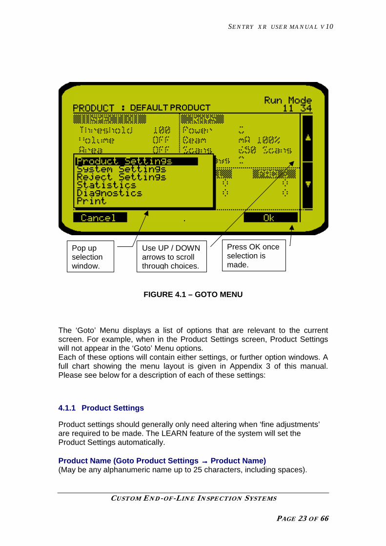
Each menu contains a record of settings arranged within sub categories. Forexample, settings relevant to rejection are within ‘Reject Settings’ and so on.These settings are easily navigated from the main ‘Run Mode’ screen by useof the ‘Goto’ button. Pressing the Goto button will pop up a menu window.Use the up / down arrows to scroll through the options and press the ‘OK’button to enter.
SENTRY XR USER MANUAL V10
CUSTOM END-OF-LINE INSPECTION SYSTEMS
PAGE 23 OF 66
FIGURE 4.1 – GOTO MENU
The ‘Goto’ Menu displays a list of options that are relevant to the currentscreen. For example, when in the Product Settings screen, Product Settingswill not appear in the ‘Goto’ Menu options.Each of these options will contain either settings, or further option windows. Afull chart showing the menu layout is given in Appendix 3 of this manual.Please see below for a description of each of these settings:
4.1.1 Product Settings
Product settings should generally only need altering when ‘fine adjustments’are required to be made. The LEARN feature of the system will set theProduct Settings automatically.
Product Name (Goto Product Settings →→→→ Product Name)(May be any alphanumeric name up to 25 characters, including spaces).
Use UP / DOWNarrows to scrollthrough choices.
Pop upselectionwindow.
Press OK onceselection ismade.
SENTRY XR USER MANUAL V10
CUSTOM END-OF-LINE INSPECTION SYSTEMS
PAGE 24 OF 66
(Manually Set)
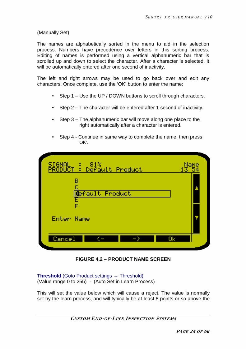
The names are alphabetically sorted in the menu to aid in the selectionprocess. Numbers have precedence over letters in this sorting process.Editing of names is performed using a vertical alphanumeric bar that isscrolled up and down to select the character. After a character is selected, itwill be automatically entered after one second of inactivity.
The left and right arrows may be used to go back over and edit anycharacters. Once complete, use the ‘OK’ button to enter the name:
• Step 1 – Use the UP / DOWN buttons to scroll through characters.
• Step 2 – The character will be entered after 1 second of inactivity.
• Step 3 – The alphanumeric bar will move along one place to the right automatically after a character is entered.
• Step 4 - Continue in same way to complete the name, then press ‘OK’.
FIGURE 4.2 – PRODUCT NAME SCREEN
Threshold (Goto Product settings → Threshold)(Value range 0 to 255) - (Auto Set in Learn Process)
This will set the value below which will cause a reject. The value is normallyset by the learn process, and will typically be at least 8 points or so above the

SENTRY XR USER MANUAL V10
CUSTOM END-OF-LINE INSPECTION SYSTEMS
PAGE 25 OF 66
general product level.The LEARN button will allow the detector toautomatically set the threshold according to the products submitted.
Threshold Offset (Goto Product settings → Threshold Offset)(Value range 0 to 255) - (Auto Set in Learn Process)
The offset value is used by the LEARN process to calculate the Thresholdvalue. It effectively sets the sensitivity of threshold detection.
When the system LEARNs the product, it finds its lowest signal point (ProductLevel). If we used this figure, then the system would always be on the verge offalse rejection.
The Threshold Offset value is used to ‘back off’ detection sensitivity to allownormal product variation to be accepted. The amount can be automaticallydetermined by the system during the LEARN process. If setting this parametermanually, values much below 8 may cause a level of false detection.
Threshold Tracking (Goto Product settings → Threshold Track)(Enable or Disable) (Manual Setting)
Threshold Tracking allows the system to ‘follow’ good products and adjust thethreshold over time to follow changes in the average product density level.
The last 50 products are used as a rolling average.
When beginning inspection, the system will use the last learnt level and beginto track from that point. If there is a large change in product density from thatlast inspected, then perform a ‘Refresh’ Learn process to create a newdetection point.
It is recommended that this feature be set to ENABLED unless the productvaries so much that it creates a ‘hunting’ effect.
Left Blanking (Goto Product settings → Left Blanking)(Value range 0 to 383). - (Auto Set in Learn Process)
This value controls the point at which the Linear Detector begins to use thesignal from the detector diodes. If, for example, set to 15, the data from diodes0 – 15 is ignored. This allows the system to ignore dense items such asproduct guides, or pack edges, or portions of the detector not normally in theX-ray beam. The system will determine an initial value for this parameterduring the learn process. DO NOT set the value to be greater than RightBlanking or the system may not function.
Right Blanking (Goto Product settings → Right Blanking)(Value range 0 to 383). - (Auto Set in Learn Process)
SENTRY XR USER MANUAL V10
CUSTOM END-OF-LINE INSPECTION SYSTEMS
PAGE 26 OF 66
This value controls the point at which the Linear Detector begins to IGNOREthe signal from the detector diodes. If, for example, set to 345, the data fromdiodes 355 – 383 (to the end of the detector) is ignored. This allows thesystem to ignore dense items such as product guides, or pack edges, orportions of the detector not normally in the X-ray beam. DO NOT set the valueto be less than Left Blanking or the system may not function.
Scan Speed (Goto Product settings → Scan Speed)(Value Range : Normal, Fast, Ultra). (Manual Setting)
This controls the speed at which the detector is scanned. The value isnormally left set to FAST. The value is NOT affected by the LEARN process.
FAST scans at 625 lines per second and allows for detection up to approx 45– 50 metres a minute.
NORMAL will scan at 400 lines per second, and can be used in applicationswhere belt speed does not exceed 20 – 25 metres a minute. The advantage ofthis setting is that greater signal is produced from the product due to thelonger ‘exposure’ time per line of the detector. (Equivalent to a longer shuttertime on a camera allowing more light onto the film.) This may allow betterpenetration and detection within the product.
ULTRA is a special mode for fast applications. If selected, the system will onlyscan the centre two-thirds of the detector (256 diodes), but at an increasedspeed of 940 scans per second. This allows a greater belt speed when usedon relatively thin products.
NOTE : Adjusting the scan speed manually will cause the system to issue awarning that you MUST restart product inspection so that it can recalibrate.Changing this setting manually will also invalidate most other productinspection levels, such as Threshold, due to the completely different X-raysignal at the detector with the revised settings.
X_ray Power Level (Goto Product settings → X-ray Power Level)(Value 1 to 4). - (Auto Set in Learn Process)
This value is determined by the LEARN process, and controls the amount ofX-ray power used on the product. Power level 1 is used on the thinnest, or lowdensity products, and power level 4 is used when the machine is inspectingthe thicker, more dense products.
The learn process selects a value that will cause the Product Level for theproduct to be over 80. If it cannot achieve this at the highest power level, it will

SENTRY XR USER MANUAL V10
CUSTOM END-OF-LINE INSPECTION SYSTEMS
PAGE 27 OF 66
indicate that it is using a lower level, or in worst cases, warn that effectiveinspection cannot be achieved.
Pack Holdon (Goto Product settings → Pack Holdon)(Value 64 to 256). - (Auto Set in Learn Process)
If using the X-ray beam to detect product presence, (rather than a PEC), afalse ‘end’ to the product may be sensed. This could be the case in, forexample, a box of cakes with 3 rows in it. The gaps between the rows may beseen as a pack end, with the pack being sensed as three different items bymistake. The Pack Holdon parameter forces the system to wait a number of‘empty’ scan lines before it decides that the pack has ended, therebypreventing premature pack end.
This parameter is checked and calculated automatically in the LEARNprocess.
Barcode (Goto Product Settings → Barcode)(May be any alphanumeric code up to 25 characters, including spaces).(Manually Set)
This is a string of characters used to represent the barcode of the currentproduct. To scan in a bar code for storage either type it manually in the editscreen or scan a real product whilst in the edit screen
During normal system operation, if a barcode scanner is attached to thesystem, when a barcode is scanned it will check all product barcodes for amatch. If a match is found, that product will be recalled. If no match is found,the status bar will flash ‘INVALID BARCODE’.
The system will then immediately begin a start up sequence on the scannedproduct, or if already inspecting, will end inspection of the previous productand restart on the newly scanned settings.
(Note that the barcode reader connects to serial port J8 of the Sentry XR).
Mass Flow Mode (Goto Product Settings → Mass Flow Mode)(Enable or Disable) (Manual Setting)
When Mass Flow Mode is DISABLED (default), the system functions asnormal. Sentry XR expects a product to have a definite start and end point –i.e, be packaged. Once the pack end is detected, the system can make anassessment of it. For example, the volume is checked at the pack end, and a

SENTRY XR USER MANUAL V10
CUSTOM END-OF-LINE INSPECTION SYSTEMS
PAGE 28 OF 66
reject is output if found out of specification. The system bases its operation oninspection of individual spaced items.
If randomly positioned products (in other words, more than one object may bepresent in the beam at the same time), such as wrapped candies areinspected, there is no ‘start and end’ of the product, as they overlap forming aconstant stream. In this case, the system cannot perform pack basedinspection. Setting the Mass Flow Mode to ENABLED hides the pack basedinspection functions, allowing only Threshold contaminant detection to beused. The following differences will be noted in this mode:
• Only Thresholding is available. The main inspection screen is revised,showing just contamination reject totals, with the pack counts andunderfill statistics ‘greyed out’.
• The Reject Graphic and Product Trace screens are not available.• The Learn facility does not determine X-ray power levels. These must
be set manually. If the system detects erroneous X-ray levels it issuesa warning.
• There is no REFRESH or FULL Learn. The system looks for 15 – 20seconds at the product passing though (mass flow) and makes adecision on the set threshold on the basis of the product that passedthrough. ONLY the threshold is learnt. Threshold Offset, blanking, etc,must be manually set. (See Note).
• There are no ‘pack based’ inspection methods – Volume and Area arehidden.
Mass Flow Mode should be set to ENABLED if the product is not a single lineof discreet packages. This will be the case if the product is randomly scattredon the belt, or passes through in more than one lane of discreet product.
Sentry XR does not support more than a single lane of product – Mass FlowMode can be used to provide Thresholding detection on ‘multiple lanes’ butthe whole belt width will be rejected.
Note: When setting up a product for the first time with Mass Flow Mode, it is best to performa Learn with Mass Flow disabled, using a sample of product for inspection. The system canthen set up the approx X-ray power and detector blanking, etc. Once these settings are found,the system can be put into Mass Flow mode, and the mass flow threshold Learntsubsequently.
4.1.2 Pack Fill Detect Settings(Goto → Product Settings → Pack Fill Detect)
The Pack Fill Detect Settings menu is available as an item selected from theProduct Menu. It contains settings directly relevant to missing or incompleteproduct detection.

SENTRY XR USER MANUAL V10
CUSTOM END-OF-LINE INSPECTION SYSTEMS
PAGE 29 OF 66
The available choices will depend upon the setting of the first menu item. Thetwo features are Volume measurement, and Area measurement.
Volume measurement performs a kind of ‘non contact weight measurement’,where product X-ray signal is converted to a series of water equivalentdensities by the system microprocessor. By doing so, the system linearisesthe signal from the detector in such a way that the signal can represent ‘slices’of product volume equivalent to a mass of water of equivalent volume to theproduct. The system can decide if there is the correct amount of product bycomparing the volume to that set in the system parameters as acceptable.This function works well on lower density products with a random positioningof contents.
Area Measurement works by counting all pixels (or diodes) that areconsidered to have product on them, set by the ‘Area Threshold’. This enablesthe system to assess the fill of a package, or level of its contents, on the basisof the number of diode scans below the set threshold.
Fill Inspection (Goto →→→→ Product settings → Pack Fill Detect → FillInspection)(Value range : Disabled, Volume, Area, Volume and Area)
The default mode is “Disabled”. With this option selected, no pack fill featuresare enabled.
If Fill Inspection is set to Volume, then the following items are displayed.
FIGURE 4.3 – VOLUME MEASUREMENT SCREEN

SENTRY XR USER MANUAL V10
CUSTOM END-OF-LINE INSPECTION SYSTEMS
PAGE 30 OF 66
Min Volume (Goto →→→→ Product settings → Pack Fill Detect → Min Volume)(Value range 0 – 65535) - (Auto Set in Learn Process)
This sets the minimum ‘Volume Units’ needed within the product for it to beconsidered a good pack. The value is calculated automatically in the LEARNprocess. The LEARN process takes a series of samples of the product, andthen sets this value to be a certain percentage LOWER than the sampledpacks, by the amount set in the Vol Offset parameter.
Max Volume (Goto →→→→ Product settings → Pack Fill Detect → Max Volume)(Value range 0 – 65535) - (Auto Set in Learn Process)
This sets the maximum ‘Volume Units’ needed within the product for it to beconsidered a good pack. The value is calculated automatically in the LEARNprocess. The LEARN process takes a series of samples of the product, andthen sets this value to be a certain percentage HIGHER than the sampledpacks, by the amount set in the Vol Offset parameter.
Vol Offset (Goto →→→→ Product settings → Pack Fill Detect → Vol Offset)(Value range 3% - 100%) - (Auto Set in Learn Process)
This controls the sensitivity of the Volume fill inspection feature. When theLEARN process sets the Min and Max volume numbers, this controls theamount by which the packs must vary to be considered incorrect, compared tothe learnt packs
If Fill Inspection is set to Area, then the following items are displayed.

SENTRY XR USER MANUAL V10
CUSTOM END-OF-LINE INSPECTION SYSTEMS
PAGE 31 OF 66
FIGURE 4.4 – AREA MEASUREMENT SCREEN
Area Threshold (Goto →→→→ Product settings → Pack Fill Detect → AreaThreshold)(Value range 0 - 255)
This controls the point at which product is considered as being available forcounting as available product area. Any diode values below this point will becounted as part of the product area under inspection.
Min Area (Goto →→→→ Product settings → Pack Fill Detect → Min Area)(Value range 0 – 65535) (Manually Set)
This sets the minimum amount of ‘diodes’ needed within the product for it tobe considered a good pack. The value is calculated automatically in theLEARN process if the feature is enabled. The LEARN process takes a seriesof samples of the product, and then sets this value to be a certain percentageLOWER than the sampled packs, by the amount set in the Area Offsetparameter.
Max Area (Goto →→→→ Product settings → Pack Fill Detect → Max Area)(Value range 0 – 65535) - (Auto Set in Learn Process)
This sets the maximum amount of ‘diodes’ needed within the product for it tobe considered a good pack. The value is calculated automatically in theLEARN process if the feature is enabled. The LEARN process takes a seriesof samples of the product, and then sets this value to be a certain percentageHIGHER than the sampled packs, by the amount set in the Area Offsetparameter.
Area Offset (Goto →→→→ Product settings → Pack Fill Detect → Area Offset)(Value range 3% – 100%) - (Auto Set in Learn Process)
This controls the sensitivity of the Area inspection feature. When the LEARNprocess sets the Min and Max Area numbers, this controls the amount bywhich the packs must vary to be considered incorrect, compared to the learntpacks. Setting to any less than approx 5% may cause a degree of falserejects due to natural variation in belt speed, and product presentation.
SENTRY XR USER MANUAL V10
CUSTOM END-OF-LINE INSPECTION SYSTEMS
PAGE 32 OF 66
4.1.3 Size Inspection Settings(Goto → Product Settings → Size Inspection)
The Size Inspection menu gives a simple means of measuring how manypixels wide, and how many lines long a product is. This can enable a form ofbasic size measurement of single lane products along the belt.
Size Enable (Goto →→→→ Product settings → Size Enable →→→→ Fill Inspection)(Value range : Disabled, Enabled)
Determines whether the Size measurement facility is to be used, and includedin the LEARN routine.
Min Width (Goto →→→→ Product settings → Min Width)(Value range 0 - 383)
This sets the minimum number of pixels wide the product needs to be toprevent an undersized reject occurring.
Max Width (Goto →→→→ Product settings → Max Width)(Value range 0 - 383)
This sets the maximum number of pixels wide the product needs to be tocause an oversize reject to occur.
Min Length (Goto →→→→ Product settings → Min Length)(Value range 0 - 383)
This sets the minimum number of lines long the product needs to be toprevent an under length reject occurring.
Max Length (Goto →→→→ Product settings → Max Length)(Value range 0 - 383)
This sets the maximum number of lines long the product needs to be to causean over length reject to occur.
Size Offset (Goto →→→→ Product settings → Size Offset)(Value range 3 – 100%)

SENTRY XR USER MANUAL V10
CUSTOM END-OF-LINE INSPECTION SYSTEMS
PAGE 33 OF 66
Used by the LEARN process to set a differential from pack parameters toactual used detection parameters.
4.1.4 Reject Settings
FIGURE 4.5 – REJECT SETTINGS SCREEN
Once again, accessed through the ‘Goto’ button, the reject settings menucontains parameters which are related to the rejection of the system. Seebelow for parameter descriptions and the view of the Reject Settings screen:
Override (Goto → Reject settings → Override)(Value range: Enable, Disable) – (Manually Set)
If this is set to ‘Enable’ , then the system is in an overridden state. This meansall detection and rejection is non-functional, however the conveyor willcontinue to run. This is useful in situations where there is no time to cure afault, but there is still a need to run a production line. The status bar will flashOVERRIDE to warn that the detector is overridden and the warning outputfrom the system is asserted.
Contaminant Delay/Distance (Goto → Reject settings → Contaminantdelay/distance)(Value range 1 to 20000 mS) – (Manually Set)
This value sets the time delay before actuating the reject mechanism. If atacho is being used then you will have to enter the actual distance from the

SENTRY XR USER MANUAL V10
CUSTOM END-OF-LINE INSPECTION SYSTEMS
PAGE 34 OF 66
centre of the detection head to the ‘centre’ of the reject device. Make fineadjustments to this value so that metal contaminated product is rejected everytime. Test with the contaminant in both leading and trailing positions on theproduct.
If a tacho device is fitted, this parameter becomes scaled in terms of distance,rather than time. The reject will be fired after the product has travelled thisamount of distance at the current measured belt speed.
Fill Delay/Distance (Goto → Reject settings → Fill delay/distance)(Value range 1 to 20000 mS) – (Manually Set)
The system allows for a separate rejection of incorrectly filled products into adifferent bin. This parameter sets the timing or distance before rejectionoccurs. It should be set to provide correct rejection as per the ContaminantDelay parameter.
Reject Duration (Goto → Reject settings → Reject duration)(Value range 0 to 20000 mS - note that ‘0’ enables Alarm & Stop mode) (Manually Set)
This value sets the duration of the reject actuation. Normally set to valuesmall enough to ensure rejection of just the contaminated product. NOTE ifthis value is set too low, then there is a chance the contaminant will not berejected. If set too high, the reject mechanism may disturb the progress of anyfollowing packs.
Reject Link (Goto → Reject settings → Reject Link)(Value range 1 to 20000 mS) (Manually Set)
Sometimes, it is possible for following products to also contain contaminants.With certain types of reject device, it is not advisable to ‘short cycle’ the rejectdevice between packs – it is preferable to maintain the reject condition untilboth items have passed. Reject Link sets the amount of belt length or traveltime that the system ‘looks back’ at to determine if a reject is following, beforeit deactivates the reject device. The feature is disabled by default.
Confirm time (Goto → Reject settings → Confirm time)(Value range 0 to 20000 mS) (Manually Set)
This value sets a time limit for confirming the rejection. A proximity switch orphoto eye can be used to detect the contaminated product as it falls from theline into the reject bin. If the photoeye does not detect it within the confirmtime then it is assumed that a known contaminated product was not rejectedand the fault relay contact will change state, allowing for an alarm etc. Settingthis value to ‘0’ will turn off reject confirmation.

SENTRY XR USER MANUAL V10
CUSTOM END-OF-LINE INSPECTION SYSTEMS
PAGE 35 OF 66
Excess rejects (Goto → Reject settings → Excess Rejects)(Value range 0 to 255 rejects per minute) (Manually Set)
If this value is set above zero, when this number of rejects is exceeded in anysingle minute, the system will alarm with a fault. The display will show a ‘HIGHREJECT RATE’ fault message. Setting this value to ‘0’ turns this feature off.
Reset Counters (Goto → Reject settings → Reset counters)This gives the option to reset the reject count. It will only reset the reject countfor the active menu. The reject count is viewable from within the‘STATISTICS’ menu.
4.1.5 System Settings
FIGURE 4.6 – SYSTEM SETTINGS SCREEN
4.1.6 Security (Passwords)
(Goto → System settings → Security)This section contains the settings for password protection on the system.
There are three levels of password protection. If there are no passwords‘Active’ then there is free access to all system settings (with the exception of

SENTRY XR USER MANUAL V10
CUSTOM END-OF-LINE INSPECTION SYSTEMS
PAGE 36 OF 66
the ‘Service Settings’ menu). The ‘Service settings’ menu is accessible only toCintex service engineers. The three password levels are:
USER – When active, this password is required for access to allsettings within the menu.
SUPERVISOR – When active this password restricts access to supervisorstatus settings.
ENGINEER – When active this password restricts access to engineerstatus settings. (See Appendix 2 at the rear of this manual).
AUTO LOG OFF – This feature may be enabled or disabled. It is only ofuse when used in conjunction with one or more of theabove password levels. If any of the above passwords areactive, then by enabling ‘Auto log off’, when using the ‘Goto’button from the Run screen, the pop-up menu will be asimplified cut-down menu with no access to editableparameter settings. In other words it is useful to enable‘Auto log off’ in order to hide the majority of sub menus fromthe operator. Access of course, may still be gained, but onlyby using a valid password.
4.1.7 Lost Or Forgotten Passwords
In the event that passwords are forgotten, then a TEMPORARY overridingpassword is accessible from the Cintex service department. The way in whichthis is used is a follows:
If a password is forgotten, then each time a password is prompted for, therewill be a 6 digit code in brackets displayed on the screen . This code can bequoted to the Cintex service department , who will then issue the customerwith a day-pass password. Note that this password will only work untilmidnight, after which it will expire. This gives allows time for the customer toreprogram their own passwords without providing a permanent means ofovercoming the password system with a ‘master’ code.
When any password has been entered successfully the currently set accesslevel will be active for 10 seconds after the last key press. If no key pressoccurs for 10 seconds, the system will revert back to the protected state.Whilst accessing a password level, the access level is displayed in the topright of the screen where the time is normally shown.

SENTRY XR USER MANUAL V10
CUSTOM END-OF-LINE INSPECTION SYSTEMS
PAGE 37 OF 66
4.1.8 Time & Date(Goto → System settings → Time & Date)
FIGURE 4.7 – TIME & DATE SCREEN
The current time and date may be edited within this menu by using the ‘Select’key to highlight the appropriate value, then using the ‘Up / Down keys to alterthe value. Once finished, press the ‘OK’ key.
4.1.9 Machine Logo(Goto → System settings → Machine Logo)(Value SentryXR, SignetXR, or other )
The machine is sold into a number of markets, where it may have differentbranding. The default name is SentryXR, which is selected by entering a valueof zero into this parameter. Other values (such as 1 for North America‘SignetXR’ ) will cause the machine logo to change.
4.1.10 Stats Archive Hour(Goto → System settings → Stats Archive Hr)(Value 0 – 23 hrs )
The system can maintain and display two days of product totals in theStatistics menu. There is usually a full 24hrs of production retained from the
SENTRY XR USER MANUAL V10
CUSTOM END-OF-LINE INSPECTION SYSTEMS
PAGE 38 OF 66
LASTDAY, as well as the TODAY under construction. This value sets the timeat which the TODAY statistics are moved to the LASTDAY totals. At this point,the completed 24hrs are moved and the totals for the current day reset.
For example, setting the value to 8 will cause a Stats Archive ‘day change’ at8.00am.
Note that if the machine is powered down for any length of time, uponreconnection, the system will perform a Stats Archive if it detects the archivetime has already passed. If ‘LASTDAY’ contains data from a much earlier timethan ‘yesterday’ it is because the system was powered down for an extendedperiod. For example, machine last used on 7th, powered down until 12th. Whenpower is applied, the LASTDAY will contain details from the 7th, and thecurrent TODAY will record details dated 12th.
4.1.11 Language(Goto → System settings → Language)(Value range English/ American/ Spanish/Dutch/German/Italian/French )
Select the appropriate language by pressing the ‘Edit’ key. Each successivepress will select a new language from the range. The American option simplyswitches the date format.
4.1.12 Machine Id(Goto → System settings → Machine ID)(Value range 0 to 999)
A unique machine ID used when performing printouts. When using severalmetal detectors, it is sensible to set a unique machine ID for each one.
4.1.13 MIACS(Goto → System settings → MIACS)(Value range ENABLED or DISABLED)
Set to ENABLED to allow the machine to be recognised on a MIACS network.
4.1.14 MIACS ADDRESS(Goto → System settings → MIACS Address)(Value range 0 - 63)
Each machine must have a unique ID to be recognised on a MIACS network.This value sets the ‘sub address’ of the machine within the ‘Line Number’group. See details of that parameter for more information.

SENTRY XR USER MANUAL V10
CUSTOM END-OF-LINE INSPECTION SYSTEMS
PAGE 39 OF 66
4.1.15 Line Number(Goto → System settings → Line Number)(Value range 0 to 63)
MIACS 2002 software allows machines to be ‘grouped together’ on thenetwork. The ‘Miacs Address’ parameter allows each machine to have aunique number WITHIN a further group defined by ‘Line Number’. Therefore,up to 64 machines can be grouped into 64 production ‘lines’ by assigningthem unique ‘Miacs Addresses’ within a ‘Line Number’ group.
4.1.13 Service SettingsGoto → System settings → Service settings)
This area of the system is Cintex password protected , and is intended onlyfor use by Cintex service personnel. A list of the functions in this area can beviewed in the Menu Layout chart in the rear of this manual.
4.1.14 Statistics(Goto → Statistics)The statistics page looks as shown below:
FIGURE 4.8 – STATISTICS SCREEN

SENTRY XR USER MANUAL V10
CUSTOM END-OF-LINE INSPECTION SYSTEMS
PAGE 40 OF 66
The meaning of the terms TODAY and LASTDAY, and the first hour entry setat the top of the screen can be found earlier in this section under the heading‘Stats Archive Hour’.
ContaminantsThis is the number of contamination rejects (Such as metal, glass, stone,bone, etc) which have occurred since the current product has been running,and within the current 24 hr logged period.
Pack FillThis is the number of pack fill rejects (such as Area and Volume) which haveoccurred since the current product has been running, and within the current24 hr logged period.
PacksThis is the total number of good and bad packs that have passed through thesystem since the current product has been running, and within the current 24hr logged period.
By pressing the Reset button, the values will be reset to a value of zero.
4.1.16 Diagnostics(Goto → Diagnostics)
This feature is for use during system fault finding, and is further detailed in thetechnical manual. It provides engineers and technicians with usefulinformation as to the health status of the main computer board and systemcomponents such as X-ray set and Linear Detector.
The contents of this menu are not needed for normal production operation ofthe system.
4.1.17 Test Settings
The test settings are relevant to the periodic testing of the metal detectorusing test pieces. See below for the test screen and a description of eachparameter:

SENTRY XR USER MANUAL V10
CUSTOM END-OF-LINE INSPECTION SYSTEMS
PAGE 41 OF 66
FIGURE 4.9 – TEST SETTINGS SCREEN
Test Interval (Goto →→→→ System settings →→→→ Test settings →→→→ Test Interval)(Value range 0 to 60 minutes)
This is the time interval at which the system will prompt the user for adetection test to be performed. The message ‘TEST REQUIRED’ will appearon the top of the screen.
Test wait (Goto →→→→ System settings →→→→ Test settings →→→→ Test Wait)(Value range 0 to 60 minutes)
This is the maximum time allowed between being informed of a requireddetection test and actually pressing the test key to perform it. If this time isexceeded, then the system will alarm with a message ‘AUTO TESTEXPIRED’.
Test Restart (Goto →→→→ System settings →→→→ Test settings →→→→ Test Restart)(value range 1 to 60 minutes)
If an auto test is not completed within the Test Wait time, a fault is generated.Once the fault has been reset, the test must be started with the Test Restarttime.

SENTRY XR USER MANUAL V10
CUSTOM END-OF-LINE INSPECTION SYSTEMS
PAGE 42 OF 66
Test Duration (Goto →→→→ System settings →→→→ Test settings →→→→ Test Duration)(Value range 0 to 60 seconds)
After the ‘Test’ key is pressed, this sets the time allowed within which to passthe test piece through the system. This time will be shown as a countdown onthe ‘Test’ screen.
Metal Test Size (Goto →→→→ System settings →→→→ Test settings →→→→ Metal Test SIze)(Value range 0 – 12mm – 0= DISABLED)
This enables a test for metallic contamination, where the size entered is aMAXIMUM acceptable contaminant size. If set to 2.4mm, the test piece will failif it is larger than this, and will be accepted if a detection occurs below thissize.
Glass Test Size (Goto →→→→ System settings →→→→ Test settings →→→→ Glass Test SIze)(Value range 0 – 12mm – 0= DISABLED)
This test is similar to the ‘Metal Test’ but will be logged by the system as aseparate test for glass.
Stone Test Size (Goto →→→→ System settings →→→→ Test settings →→→→ Stone Test SIze)(Value range 0 – 12mm – 0= DISABLED)
This test is similar to the ‘Metal Test’ but will be logged by the system as aseparate test for Stone.
The terms “Metal, Glass and Stone” have been used to signify commoncontaminants. The Event History LOG (and MIACS) will enter the name of thetest passed or failed according to the test being performed. It is clearlypossible for the user to substitute other types of contamination for the namesgiven. For example, bone could be used instead of glass, rubber instead ofstone. The system does not differentiate between ACTUAL types ofcontamination, it is the size of the contamination and the completion of thetest that is important.

SENTRY XR USER MANUAL V10
CUSTOM END-OF-LINE INSPECTION SYSTEMS
PAGE 43 OF 66
5 AUTOMATIC LEARNING AND PRODUCT TESTS
This section describes the basic procedure for AUTOMATICALLY setting up aproduct on the CINTEX Sentry XR Inspection System.
The first step in creating a product menu is to enter the product name. When aname is entered, default values are created, than need ‘tuning’ by the processof learning the product. Once a product is learnt, the menu and its results arerelevant to that particular product only.
5.1 LEARNING – AN OVERVIEW
Before we discuss setting up a product, the following should be considered :
• It is important that the product used during setup is typical of producttaken directly from the production line, and has not been stored,allowed to go stale or otherwise damaged, as the learning results coulddiffer.
• Product used during the learn process SHOULD NOT containcontaminants planted inside for detection tests.
• USE FIVE DIFFERENT SAMPLES OF THE PRODUCT DURING THE‘REFRESH’ OR PARAMETER LEARN PHASE OF THE SETUP. Thisenables the system to get a better indication of normal productvariation.
• The LEARN process sets up the detection of the system. It does NOTset the reject timing, which should be adjusted by the operator tovisually confirm product is being properly rejected.
• The system will disable rejection and detection during the procedure,and will not count or log any packs or reject events in the statisticsduring LEARN time.
Products used during LEARN are not inspected for contaminant and fill levelduring setup, and will need to be removed from the line and resubmittedduring normal run time.

SENTRY XR USER MANUAL V10
CUSTOM END-OF-LINE INSPECTION SYSTEMS
PAGE 44 OF 66
The learn process is simple to perform, and can take two forms.
5.1.1 FULL Learn
When setting up a product ‘from scratch’ a FULL Learn must be used. A FULLLearn consists of two phases. The first requires that a series of packs arepassed through the system so that it can determine the correct X-ray powerand detector settings. The second part of the process is that used by theREFRESH Learn, where the system samples the submitted product, and setsup the actual detection parameters such as Threshold, and Area, etc.
5.1.2 REFRESH Learn
A REFRESH Learn is performed periodically on a previously set up product to‘freshen up’ the current detection settings. This enables the system to re-adjust to any variations in the current product, and remove any long term driftfrom the system.
5.2 PERFORMING A FULL LEARN
Choose an existing, or create a new product for inspection. Start the machineup on the product to be learnt.
Once the machine is showing the Runmode screen, you should press theOPTIONS key at the foot of the screen. A sub-menu will pop up. SelectLEARN.
FIGURE 5.1 – SELECTION OF LEARN FUNCTION
SENTRY XR USER MANUAL V10
CUSTOM END-OF-LINE INSPECTION SYSTEMS
PAGE 45 OF 66
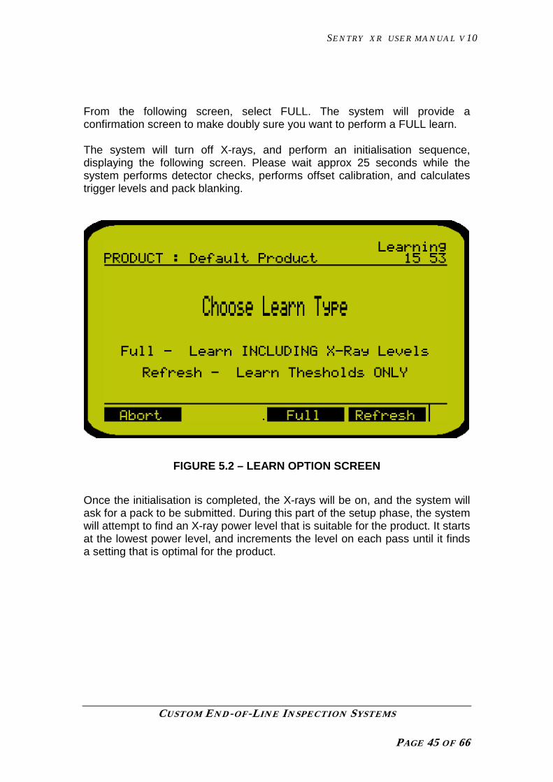
From the following screen, select FULL. The system will provide aconfirmation screen to make doubly sure you want to perform a FULL learn.
The system will turn off X-rays, and perform an initialisation sequence,displaying the following screen. Please wait approx 25 seconds while thesystem performs detector checks, performs offset calibration, and calculatestrigger levels and pack blanking.
FIGURE 5.2 – LEARN OPTION SCREEN
Once the initialisation is completed, the X-rays will be on, and the system willask for a pack to be submitted. During this part of the setup phase, the systemwill attempt to find an X-ray power level that is suitable for the product. It startsat the lowest power level, and increments the level on each pass until it findsa setting that is optimal for the product.

SENTRY XR USER MANUAL V10
CUSTOM END-OF-LINE INSPECTION SYSTEMS
PAGE 46 OF 66
FIGURE 5.3 – XRAY POWER WAITING FOR PACK SCREEN
Once the pack is passed through, the screen will indicate it has found thepack.
FIGURE 5.4 – XRAY POWER CALCULATION SCREEN
If more X-ray power is needed, the system will set up on a new power level,and ask for a further pack. It may take up to four passes for the system todetermine the correct X-ray power levels.

SENTRY XR USER MANUAL V10
CUSTOM END-OF-LINE INSPECTION SYSTEMS
PAGE 47 OF 66
Approx 15 seconds will be needed between pack submissions for the X-raysto re-adjust – do NOT pass a pack unless the screen instructs you to do so orthe learn will be compromised.
If you wait more than 10 seconds after the system has requested a pack, thesystem will ‘time out’ and exit the Learn process.
If the X-ray level is suitable, the system will progress to the ‘REFRESH’ part ofthe learn process. During the REFRESH learn, the system will ask for fivefurther passes of pack.
5.3 PERFORMING A REFRESH LEARN
A REFRESH Learn can be preformed on a product that has been previouslyset-up, in order to ‘freshen’ and fine tune the detection to variations in productbatches.
It is also used as the second phase of the FULL learn process.
When used on its own, REFRESH can be used whilst products are passing‘live’ – the system will detect the start and end of the products, until it registersand samples the data it needs. You do not have to submit products one at atime.
Products used during the LEARN process are not inspected for contaminantand fill level, and will need to be removed from the line and resubmitted duringnormal run time.
To use REFRESH independently of the FULL learn, press the OPTIONS keyduring normal inspection. The system will provide a pop-up menu, from whichLEARN should be selected. From the screen that follows, press theREFRESH button
The system will request three or five packs of UNCONTAMINATED product,which should ideally not be the same pack on each pass. The machine takesapprox 3 – 4 seconds to calculate the settings, so it is possible to presentpacks almost as fast as is practical.
After the learn process has completed, a conformation screen will be shownwith the values learnt. If you are happy with the results, SAVE them orABORT to retain the previous settings.

SENTRY XR USER MANUAL V10
CUSTOM END-OF-LINE INSPECTION SYSTEMS
PAGE 48 OF 66
If, for any reason a problem occurs during LEARN or an incompatible productis presented, the system may abort the procedure and show a warning, suchas the following.
FIGURE 5.5 – LEARN FAIL SCREEN
The system will exit inspection automatically on a LEARN fault. Correct thefault, and re-submit the product for learn. Please note, that after a failed learn,product settings MAY need manually adjusting for the failed product, and anew detector calibration will be needed.
Once the product has been learnt, it will be necessary to manually adjust thereject settings, as detailed in the next section.
5.4 SETTING THE REJECT TIMING

SENTRY XR USER MANUAL V10
CUSTOM END-OF-LINE INSPECTION SYSTEMS
PAGE 49 OF 66
If NO reject device is present i.e. the system is Audible alarm & belt stop thensimply set the ‘Reject Mode’ as follows:
Select : Goto →→→→ Reject Settings →→→→ Reject Duration
and set the Reject Duration to ‘0’. A value of ‘0’ here denotes ‘Alarm andStop’.
• Make sure the Override is set to ‘Disable’ and pass a GOOD productthrough the detector and check that there is no detection .
• Pass a product with the required test sample and check that it isdetected.
• The system settings can be adjusted to suit the test sample required ora LEARN performed if the system is not detecting.
TEST SAMPLES CAN BE SUPPLIED BY CINTEX .
• Once the machine has been set up for the product and is detectingyour metal samples, enter a suitable value of the ‘Reject Delay’. This isthe time (or distance) to wait between actual detection within the ‘head’and operating the reject. This is accessed as follows:
[Goto →→→→ Reject Settings →→→→ Contaminant (or Fill) Delay]
• Enter also a suitable value for the ‘Reject duration’, this is the length oftime that the reject will operate. Accessed as follows:
[Goto →→→→ Reject Settings →→→→ Reject Duration]
• If you are utilising reject confirmation then enter a suitable time herewhich is long enough to allow the confirmation to take place . This isaccessed as follows:
[Goto →→→→ Reject Settings →→→→ Confirm Time]
If confirm time is set to zero, then reject confirm is automatically turned off.
Submit the product through the system several times, observing the rejectaction. If the reject device operates early, increase the value of the ‘Delay’parameter until the reject is optimal. Similarly, if the device operates too late,decrease the value. When the timing is correct, adjust the value of ‘Duration’such that the mechanism operates long enough to push off the package, butnot so long as to obstruct any following pack.
5.5. PRODUCT TESTS

SENTRY XR USER MANUAL V10
CUSTOM END-OF-LINE INSPECTION SYSTEMS
PAGE 50 OF 66
The ‘Manual System Setup and Menu Structure’ section details the settingsused to define the behaviour of the Product Tests. Sizes can be set for up tothree test objects, being normally Metal, Glass and Stone. The system can beset to request a test sequence at regular intervals. If these tests are notperformed or completed, the system will give a fault indication, and log thefailure in the event log, and pass the results over the MIACS network.
If the tests complete successfully, then a pass is logged and transmitted overthe optional network.
The system will indicate a test is needed by showing a warning at the top ofthe screen.
FIGURE 5.6 – TEST DUE INDICATION
The tests use up to three samples for detection, being Metal, Glass, andStone by default. This is to enable the user to log three separate types ofcontaminants for test purposes. The tests performed are identical for eachitem. If the customer wishes, ‘Stone’ may be a bone test piece, or ‘Glass’ maybecome a dense plastic test piece. It is a matter of procedure as to the testsamples and sizes used, but the system will log and record them in thecategories given.
Note that during the time a test is being requested, the ‘warning’ and the ‘autotest required’ will be asserted on the system. If a test is not completed or if itfails then the ‘fault’ outputs will be asserted.

SENTRY XR USER MANUAL V10
CUSTOM END-OF-LINE INSPECTION SYSTEMS
PAGE 51 OF 66
The user should select the TEST feature from the OPTIONS menu as shownin the figure.
FIGURE 5.7 – TEST SELECTION SCREEN
The system will ask for the first contamination test piece to be submitted viathe following screen.

SENTRY XR USER MANUAL V10
CUSTOM END-OF-LINE INSPECTION SYSTEMS
PAGE 52 OF 66
FIGURE 5.8 – TEST SUBMISSION SCREEN
The test piece should be mounted on a flat card, or other low density carriermedium, or taped over the product.
It is important to note that X-ray detection works on a density differenceprincipal. You MUST ensure that the contaminant is placed OVER or INthe actual product. If the contaminant is placed in or over a productvoid, or away from the product (not actually in the product mass) adifferent (lower) level of sensitivity will result.
Submit the test piece and pack to the system on the conveyor belt. If you donot do so within a time period set in the parameters, the system will signal afault. (This is to prevent operators defeating the test system, by making theequipment think it is always in the middle of performing a test!)
The system will detect the pack, and make a decision on the contaminantwithin it.
If the contaminant is found, the system will move onto the next (ifprogrammed) test sample. If the contaminant is NOT found, then the followingscreen will display.

SENTRY XR USER MANUAL V10
CUSTOM END-OF-LINE INSPECTION SYSTEMS
PAGE 53 OF 66
FIGURE 5.9 – TEST FAIL SCREEN
If the contaminant is found to be of an excessive size (more than allowed inthe test settings menu) then the system will show a fail screen, and a faultstatus will be issued until the tests are successfully completed on asubsequent test sequence.
Once all test pieces have passed, the system will return to normal inspectionstate until the next test period becomes due.

SENTRY XR USER MANUAL V10
CUSTOM END-OF-LINE INSPECTION SYSTEMS
PAGE 54 OF 66
6. PERIPHERAL DEVICES
There are a number of peripheral devices which may be connected to theSentry XR system. These are:
• Serial Printer.• Serial Barcode scanner.• MIACS network connection.
6.1 SERIAL PRINTER
Some users may wish to download information from the Sentry XR and print itout directly, allowing keeping hard-copy records.
The printer is connected to the system via an (optional) connector on theoutside of the system. It can be fitted during manufacture or as an upgrade inyour factory. If the connector is present, you have access to the following.
The information which may be printed is listed below:
• Statistics (information as viewed on the Statistics page).• Product settings (all parameters in the Product settings and Reject
settings menus).• System settings (all parameters in the System settings menu).• Reject settings (all parameters in the Reject settings menu).• Advanced settings (all parameters in the Advanced settings menu).• Test settings (all parameters in the Test settings menu).• Service settings (all parameters in the Service settings menu).• System information (all information from the Diagnostics screen).• Log (all the events shown in the log from the Diagnostics screen).• Entire system (all of the parameters shown above, excluding the log).
In order to print out any of this information, simply select:
(Goto →→→→ Print →→→→ (Make selection) →→→→ Print)
The information will be sent to the printer. If no printer is present, or the optionis not fitted, the data will remain in a buffer until one is connected or thesystem is powered down.

SENTRY XR USER MANUAL V10
CUSTOM END-OF-LINE INSPECTION SYSTEMS
PAGE 55 OF 66
6.2 SERIAL BARCODE SCANNER
There is an option to connect a serial barcode scanner to the Sentry XRsystem. The barcode scanner is a great aid in the operation of the system.The machine can start on any pre-programmed product by simply ‘swiping’ apack with the reader. The system will automatically set up and run on theproduct, provided a match for the barcode is found . This feature removes therisk of an operator selecting the wrong menu for the product, andsubsequently compromising inspection quality.
The barcode scanner is connected to the system via an (optional) connectoron the outside of the system. It can be fitted during manufacture or as anupgrade in your factory.
During product setup, a barcode may be scanned in for any product menu, byperforming the following:
(Goto →→→→ Product settings →→→→ Barcode →→→→ Edit)
Then ‘swipe’ the pack with the scanner to read in the code. The number willappear across the middle of the LCD screen. Alternatively the number may bemanually entered. Once entered press the OK button to accept it. If for anyreason a barcode is scanned which already exists, then a warning “Barcodealready exists” will appear on the screen and the barcode must be altered tobe unique.
When in production, if a barcode is scanned in and a match is found, thematching menu will become the active menu. If the system is alreadyinspecting, the system will end inspection, and restart on the new product.
6.3 MIACS (MANAGEMENT INFORMATION AND CONTROL SYSTEM)
MIACS is a proprietary networking software package provided by Cintex forconnecting multiple Cintex systems together in a peer-to-peer network. Thisallows systems to ‘talk to each other’ and be monitored and controlled by aremote PC. The user may monitor system operation, and gather informationand create reports with a Windows PC from an office or lab environment.MIACS also provides a secondary means or demonstrating that Cintexequipment was functional, and what the operating parameters were, duringany production incident.
All systems have MIACS support in the internal software. To enable its use, itis necessary to provide cabling between systems, a remote PC and a copy ofMIACS needs to be setup on the PC.
Systems can be networked at installation times, or as a future upgrade.

SENTRY XR USER MANUAL V10
CUSTOM END-OF-LINE INSPECTION SYSTEMS
PAGE 56 OF 66
7. BACKING UP VITAL SYSTEM DATA AND MENUS
It is advisable to have a back up copy of the menu settings in the event of aloss of settings, or if someone mistakenly changes the settings.
There are two methods of keeping a backup.
EEprom MemoryThe primary method of backing up settings is found in the Product Settingsscreen. There are two options related to backing up. These are :
(Goto →→→→ Product Settings →→→→ System Backup)
This function will save ALL system settings to a battery and powerindependent store in system memory. It can be recalled, restoring thepreviously backed up settings by selecting
(Goto →→→→ Product Settings →→→→ System Recall)
NOTE THAT any changes made since the last Backup, will be over-written ifRESTORE is used. This means that any more recent adjustments or newproducts entered will be lost, being replaced with the state of the system atthe time of the last System Backup.
Printouts / Hard CopyIf the system is fitted with the optional printer connector, there is a facility toprint out the settings and keep a hard copy. If the printer facility is present, it isrecommended that once the detector is set up, that a hard copy of the settingsbe kept, in either printed or hand written form.

SENTRY XR USER MANUAL V10
CUSTOM END-OF-LINE INSPECTION SYSTEMS
PAGE 57 OF 66
8. TROUBLESHOOTING AND SERVICING
The Sentry XR has no operator serviceable parts inside. Customer staff areonly expected to perform simple external system maintenance such ascleaning, air filter replacement, and conveyor belt changing.
Most internal servicing, apart from fuse replacement and simple wiring faults,require specialist training. Customer engineers can be given sufficient trainingto service the machine if required, but those without the proper certificationshould not dismantle internal parts.
DO NOT UNDER ANY CIRCUMSTANCES DEFEAT SYSTEM INTERLOCKS
If qualified site staff are advised by Cintex to make internal checks oradjustments, obey and follow directions as they are given by our trained staff.
8.1 SERVICE PROMPT
When a service is due, there will be a screen prompt in the top right corner asillustrated in the figure.
FIGURE 8.1 – SERVICE INDICATOR
In the top right corner of the screen where the time and date are shown, aservice indicator will be present showing a countdown series of four boxes.

SENTRY XR USER MANUAL V10
CUSTOM END-OF-LINE INSPECTION SYSTEMS
PAGE 58 OF 66
The service indicator will appear 4 weeks before the due date and as the fourweeks pass, another box will be highlighted, until the message eventuallyappears as ‘ Service Due’. The prompt will be cleared by the service engineeronce the service has been completed.
8.2 BASIC FAULT FINDING
If the equipment malfunctions, see if the fault indicated appears in the tablesand take the suggested action. All these checks must be carried out bycompetent personnel taking appropriate precautions.
If a fault persists, try turning the machine off for 10 seconds, then on again –this may clear the fault.
If detection is erratic or non existent, then re-learn the product, or create anew test product on a fresh menu. Faults are quite often as a result ofoperators changing settings to incorrect values – creating and learning a newproduct may highlight this if it begins to work.
If the fault cannot be cleared, contact Cintex for service or advice.
Run Mode Screenpermanentlydisplays“CONTAMINANT’or other rejectstate instead of“Waiting ForPack”.
The system is not receiving a calibrated X-ray signal, orthe current product settings are wrong.
Stop the system, and restart it, performing a calibration.Note any fault conditions and correct them.
Create a new product on an unused menu. Complete alearn process. If a fault persists on the new product,consult Cintex for advice.
‘Reject ConfirmFault’ message.
The reject mechanism is operating too slowly or hasfailed. Taking appropriate precautions:-Check any high pressure air supply.Check that the reject mechanism can move freely.Check the actuator.Check continuity of any solenoids, solenoid valves etc.Check the operation of the reject mechanism sensor e.g.microswitch. If reject confirm is not needed then ensurethe Confirm Time is set to zero in the Reject settingsmenu.
‘System Fault’ A hardware error occurred on the main board, Contact

SENTRY XR USER MANUAL V10
CUSTOM END-OF-LINE INSPECTION SYSTEMS
PAGE 59 OF 66
message. Cintex if fault persists.
‘24v power supplyfault’ message
Check fuse F1 on the motherboard. The system 24vdchas failed.
‘Temperature faultmessage’
An overtemperature has occurred, within the systemcabinet. Check that air intakes and filters areunobstructed and clean, and that any air conditioner(optional) is functional.
‘Battery Back UpFailed’ message.
The main settings are held in battery backed RAM. TheRAM is powered from a lithium battery. If the unit is leftpowered down for long periods (months) or if the batteryis faulty, then this fault message will occur. Settings willbe loaded from the backup EEPROM in this case. Thesemay not be your current settings……
‘X-ray Set’ faults.If an interlock is opened, an Emergency stop pressed, orthe Enable key is inactive, X-rays will not be producedand the system will provide a fault message. Check allsafety devices are enabled, and restart inspection. If thefault persists, consult Cintex.
‘Low Air Pressure’message.
The incoming air pressure has dropped below anacceptable level. This input is unused on upgrades asthe air pressure fail is transparent to the computer, itsimply trips the fault circuit.
‘Reject Bin full’message
The reject bin full sensor has been activated. Clear thebin of product and ensure the sensor is functioning.This input is unused on upgrades, as the bin full sensorsimply trips the fault circuit
‘Excess Rejects’message.
The number of metal rejects in any one minute hasexceeded the limit. Either investigate the product orreduce the ‘Excess rejects’ setting in the ‘Reject Settings’menu.
‘Detector Fault’messages.
Indicate that there is a problem with the Linear detectorarray. Power the system down for five seconds, then reapply power and calibrate the product. If the faultpersists, consult Cintex.
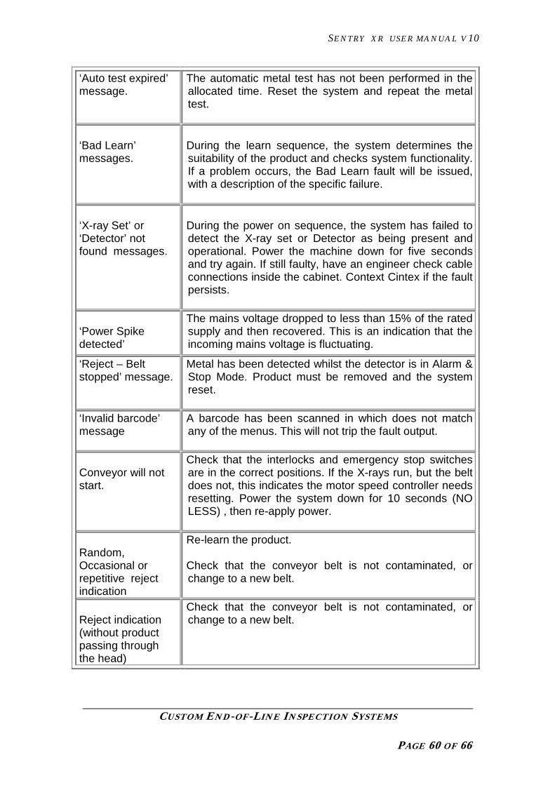
SENTRY XR USER MANUAL V10
CUSTOM END-OF-LINE INSPECTION SYSTEMS
PAGE 60 OF 66
‘Auto test expired’message.
The automatic metal test has not been performed in theallocated time. Reset the system and repeat the metaltest.
‘Bad Learn’messages.
During the learn sequence, the system determines thesuitability of the product and checks system functionality.If a problem occurs, the Bad Learn fault will be issued,with a description of the specific failure.
‘X-ray Set’ or‘Detector’ notfound messages.
During the power on sequence, the system has failed todetect the X-ray set or Detector as being present andoperational. Power the machine down for five secondsand try again. If still faulty, have an engineer check cableconnections inside the cabinet. Context Cintex if the faultpersists.
‘Power Spikedetected’
The mains voltage dropped to less than 15% of the ratedsupply and then recovered. This is an indication that theincoming mains voltage is fluctuating.
‘Reject – Beltstopped’ message.
Metal has been detected whilst the detector is in Alarm &Stop Mode. Product must be removed and the systemreset.
‘Invalid barcode’message
A barcode has been scanned in which does not matchany of the menus. This will not trip the fault output.
Conveyor will notstart.
Check that the interlocks and emergency stop switchesare in the correct positions. If the X-rays run, but the beltdoes not, this indicates the motor speed controller needsresetting. Power the system down for 10 seconds (NOLESS) , then re-apply power.
Random,Occasional orrepetitive rejectindication
Re-learn the product.
Check that the conveyor belt is not contaminated, orchange to a new belt.
Reject indication(without productpassing throughthe head)
Check that the conveyor belt is not contaminated, orchange to a new belt.
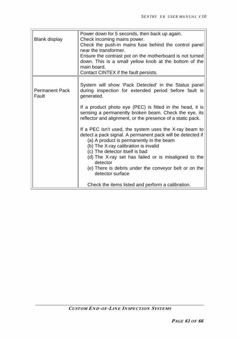
SENTRY XR USER MANUAL V10
CUSTOM END-OF-LINE INSPECTION SYSTEMS
PAGE 61 OF 66
Blank displayPower down for 5 seconds, then back up again.Check incoming mains power.Check the push-in mains fuse behind the control panelnear the transformer.Ensure the contrast pot on the motherboard is not turneddown. This is a small yellow knob at the bottom of themain board.Contact CINTEX if the fault persists.
Permanent PackFault
System will show ‘Pack Detected’ in the Status panelduring inspection for extended period before fault isgenerated.
If a product photo eye (PEC) is fitted in the head, it issensing a permanently broken beam. Check the eye, itsreflector and alignment, or the presence of a static pack.
If a PEC isn’t used, the system uses the X-ray beam todetect a pack signal. A permanent pack will be detected if
(a) A product is permanently in the beam(b) The X-ray calibration is invalid(c) The detector itself is bad(d) The X-ray set has failed or is misaligned to the
detector(e) There is debris under the conveyor belt or on the
detector surface
Check the items listed and perform a calibration.

SENTRY XR USER MANUAL V10
CUSTOM END-OF-LINE INSPECTION SYSTEMS
PAGE 62 OF 66
9. CE AND SAFETY COMPLIANCE
The system is CE marked and compliant with all the standards listed in theaccompanying declaration of incorporation. The equipment is supplied with adeclaration of incorporation rather than a declaration of conformity becausethe safety of the final installation is dependent upon adjoining machinery. Forexample, some applications may require additional covered conveyor areaseach side of the machine if curtain are not used on the infeed and outfeedapertures. Consult EN294: Safety of Machinery, and X-ray regulationsrelevant to your country for more details on how to construct a safeinstallation. Particular attention should be paid to the correct connection ofthe safety earth, which should be connected directly to the stud marked PE.
The Sentry XR incorporates the capability to run all conveyor peripherals suchas reject solenoid, contactor etc from 24V A.C., thus providing transformerisolation and low voltage operation.
Over current protection on the 24 volt lines is provided by a 2A anti surge fuse(F1) located on the mother board and an additional 2A mains fuse on theincoming mains terminals at the rear of the control panel. Incoming power tothe system is take through two sets of circuit breakers, accessible from therear of the machine. A further fuse for the main internal 24v DC supply iscontained within the 24v psu unit at the rear side wall of the machine.
Ensure that you are aware of the regulations for the use of X-ray equipment inyour country relevant to your application. Cintex or their agents can supplyspecific details of your responsibilities on request.

SENTRY XR USER MANUAL V10
CUSTOM END-OF-LINE INSPECTION SYSTEMS
PAGE 63 OF 66
10. BASIC SPECIFICATION
Mains supply 100,110,120,220,240V AC+ 10 - 15%50 - 60Hz single phase0.4kw nominal (up to 5A surge at power on)
NOTE: Adjustment is required within the system to Select appropriate supply range.
Ambient temp. 0 to + 35 degrees C non condensing
Hose resistance External surfaces resistant to a jet from a hose of12mm (0.5”) bore under a pressure of 3.5Kg/cm(50psi) from a distance of 0.6M (24”).
This exceeds IP65 and NEMA 4.(See note [1] below for exceptions)
Speed Range 10-45Mtrs/min according to application
Battery Back up Average cell life 5 years in normal operationDischarge time 18 months from power off
Electrical Switching:-Relay Outputs Maximum switched voltage 120Vac, 28vdc.
Maximum switched current 3A Note: These terminals are NOT designed to switch 220 – 240v mains voltages
Opto inputs Nominal 24vdc (Maximum Voltage: + 30V) Max. sink current 20 mA.
Sensitivity Dependent on product and application .
[1] This specification DOES NOT apply to the rear air intakes / outlets which should be covered duringcleaning. The internal conveyor mechanism and detection chamber / detector should be wiped clean bya cloth and mild detergent and NOT subjected to copious quantities of water.

SENTRY XR USER MANUAL V10
CUSTOM END-OF-LINE INSPECTION SYSTEMS
PAGE 64 OF 66
11. COMMONLY USED PARAMETERS GLOSSARY
NAME DESCRIPTION DEFAULT MIN MAX ACCESSLEVEL
Threshold If the contaminant level falls below this value, areject is issued
100 0 100 SUPERVISOR
Threshold Offset Amount below the product level at which theThreshold is set
8 0 255 SUPERVISOR
ThresholdTracking
Allows system to continually adjust Thresholdvalue according to the average of the last 50good packs
ON OFF ON SUPERVISOR
Left Blanking The diode at which the detector begins tooutput data – i.e, is active
0 383 0 SUPERVISOR
Right Blanking The diode at which the detector stopsoutputting data – i.e, is inactive
383 0 383 SUPERVISOR
Scan Speed Controls the amount of ‘slices’ of productscanned per second.
FAST Normal Ultra SUPERVISOR
X-ray power level Controls the intensity of the X-ray beam 2 1 4 SUPERVISOR
Name Product name ---------------- - - SUPERVISOR

SENTRY XR USER MANUAL V10
CUSTOM END-OF-LINE INSPECTION SYSTEMS
PAGE 65 OF 66
NAME DESCRIPTION DEFAULT MIN MAX ACCESSLEVEL
Barcode Product Barcode. Used by attached barcodescanner.
- - SUPERVISOR
Mass Flow Mode Allows use on non discreet (unpackaged) orloose products. Only Thresholding is available.
DISABLED DISABLED ENABLED SUPERVISOR
Pack HoldOn Pack HoldOn. Amount of lines of blank imagebefore pack end is signalled.
64 64 256 SUPERVISOR
Contaminant or FillDelay
Delay AFTER detection before reject outputoperates
2000ms 1 20000 SUPERVISOR
Reject Duration Length of time reject operates for. 800ms 0 20000 SUPERVISOR
Confirm Time Time limit allowed after reject operates duringwhich reject confirm input must be activated.
0ms 0 20000 SUPERVISOR
Excess Rejects Maximum rejects per minute rate. 0rpm 0 20000 SUPERVISOR
Reject Link Time in which to link two consecutive rejectstogether.
0ms 0 20000 SUPERVISOR
Other Parameter descriptions and Setup information is contained within the Sentry XR Technical Manual.

SENTRY XR USER MANUAL V10
CUSTOM END-OF-LINE INSPECTION SYSTEMS
PAGE 66 OF 66
12. MENU LAYOUT
Tests Log
OverrideContam’t DelayFill DelayReject DurationConfirm TimeExcess RejectsReset Counters
UserSupervisorEngineerAuto log off
Test IntervalTest WaitTest restartTest DurationMetal Test SizeGlass Test SizeStone Test Size
TestAbort
(Inspection)
CopyDeleteRecallNew
Goto
Option
Start
Menus
Maintenance ModeDe’ctr Temp CompBad Diode CorrectSystem BackupSystem RecallPack Detect PECStart On ConveyorBack light timeFault DetectionTachoRS232 Baud rateRS485 Baud ratePrinter bufferNext serviceService code
Product SettingsSystem SettingsReject SettingsStatisticsDiagnosticsPrint
Fill Inspect ModeMin VolumeMax VolumeVolume OffsetArea ThresholdMin AreaMax AreaArea Offset
Security Test Settings Time & DateMachine LogoStats Archive HrLanguageMachine IDMIACSMIACS AddressLine numberService Settings
Name BarcodeThreshold Threshold OffsetL and R Blanking Scan SpeedX-ray Level Pack HoldOnPack Fill Detect Size InspectionReject SettingsSystem SettingsBackup + Recall