Embed Size (px)
Citation preview

Copyright © by A. Adler, 2009-2017 (including Material from J.G. Webster)
Sensors
Slide 07B.1Sensors
Sensor: device which detects changes in quantities of interest and provides a
readable output
ExamplesThermocouple converts temperature to voltage.Mercury thermometer converts temperature to a reading on a calibrated glass tube.

Copyright © by A. Adler, 2009-2017 (including Material from J.G. Webster)
Sensors
Slide 07B.2
Instrument Characteristics:Resolution and Sensitivity
Resolution Smallest change
measurable
Sensitivity
= (∆signal)/(∆measurand)
Low sensitivity High sensitivity
measurand
sig
nal
∆measurand
∆si
gn
al

Copyright © by A. Adler, 2009-2017 (including Material from J.G. Webster)
Sensors
Slide 07B.3Linearity and operating range
Many sensors have a linear operating range.
Outside this range we have the maximum operating range (that doesn’t damage the instrument)
50
-20
Thermometer
50
-20
-20 50
Melting
Temperature(input)
Reading on thermometer
(output)
Maximum Range
LinearRange

Copyright © by A. Adler, 2009-2017 (including Material from J.G. Webster)
Sensors
Slide 07B.4Sensors
Sensor Types: Displacement Sensors: measure movement
Resistive Inductive Capacitive Piezoelectric
Temperature Measurement Thermistors Thermocouples

Copyright © by A. Adler, 2009-2017 (including Material from J.G. Webster)
Sensors
Slide 07B.5Potentiometers
Resistive ElementWiper
Fixed ContactsFixed Contacts
Image source:WikipediaConstruction
Wire wound Carbon film Ceramic Conducting plastic

Copyright © by A. Adler, 2009-2017 (including Material from J.G. Webster)
Sensors
Slide 07B.6Question:
If we apply 10V across a single turn potentiometer with 50 wire turns covering 360º.
What is sensitivity (in volts/degree)?
What is resolution?

Copyright © by A. Adler, 2009-2017 (including Material from J.G. Webster)
Sensors
Slide 07B.7Strain Gauges
Strain gauge measures strain (deformation) by a change in resistance.
Measurement circuits typically use “Wheatstone bridge” – describe next section
Connecting Pads
Se
ns
itiv
e D
ire
ctio
n Gauge Factor: measure of gauge sensitivity
GF = ( ∆R/R ) / strain
R: undeformed resistance∆R: change in R due to strainstrain: fractional change in length (∆L/L)

Copyright © by A. Adler, 2009-2017 (including Material from J.G. Webster)
Sensors
Slide 07B.8Strain Gauge Examples
Bonded: (more typical) bonded to device with adhesive (superglue)
Resistance Wire Foil Helical Wire
Unbonded:mounted freely (ends bounded to device)
Armature
Strain-gage wires
A
DC
B
Diaphragm
Unbonded strain-gage pressure sensor. With increasing pressure, the strain on gage pair B and C is increased, while that on gage pair A and D is decreased

Copyright © by A. Adler, 2009-2017 (including Material from J.G. Webster)
Sensors
Slide 07B.9Strain Gauge Examples
Integrated pressure sensor. Diaphragm deforms if pressures on each side are unequal.
Deforming strain gauges
References gauges
Pressure(measurand)
P. reference(atmosphere)

Copyright © by A. Adler, 2009-2017 (including Material from J.G. Webster)
Sensors
Slide 07B.10Strain Gauge: analysis
Analysis of SGArea
(A)
Length (l)
resistivity (ρ)
Poisson’s Ratio (µ)
For incompressible media µ=0.5. Calculate from Vol = D2L is const
∂ A2A
=−∂ LL
R =LA
∂R =LA
∂
A∂L−
L
A2 ∂ A
∂RR
=∂
∂LL
−∂ AA
∂RR
=∂
12
∂LL
G =∂ R/R∂L /L
=12∂/
∂ L/L

Copyright © by A. Adler, 2009-2017 (including Material from J.G. Webster)
Sensors
Slide 07B.11Strain Gauge: analysis
Gage Factor
DimensionalEffect
Piezoresistive Effect- Metals ≈ 0- Ceramics / Semiconductors
have large effect Examples:- Metals G = 1+2(0.3) = 1.6- n-Si G ≈ 100- p-Si G ≈ -100
(large temperature drift in semis)
G=∂ R/R∂L /L
= 12 ∂/
∂ L/L

Copyright © by A. Adler, 2009-2017 (including Material from J.G. Webster)
Sensors
Slide 07B.12Question
Mercury plethysmograph measures change in leg blood volume after pressure cuff applied (venous occlusion)
µ for Hg is 0.5 Calculate ∆R/R
if blood makes10% increase inleg cross section
Copyright © by A. Adler, 2009-2017 (including Material from J.G. Webster)
Sensors
Slide 07B.13Inductive Sensors
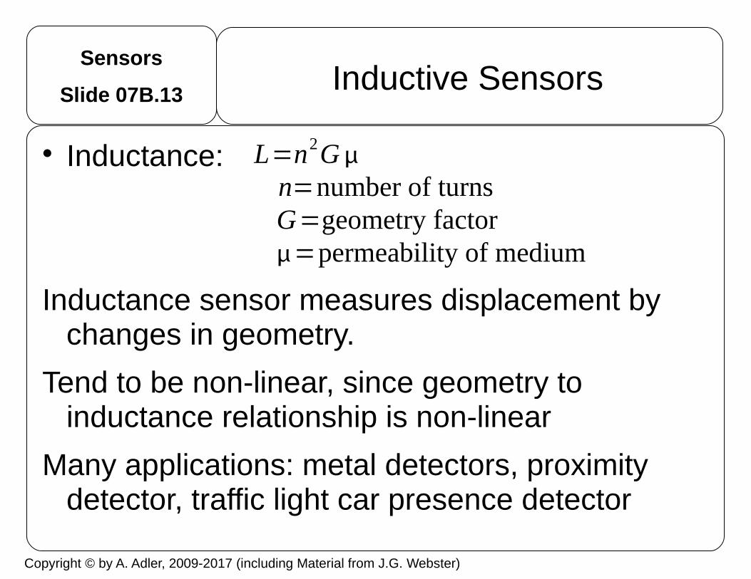
Inductance:
Inductance sensor measures displacement by changes in geometry.
Tend to be non-linear, since geometry to inductance relationship is non-linear
Many applications: metal detectors, proximity detector, traffic light car presence detector
L=n2Gn=number of turnsG=geometry factor=permeability of medium

Copyright © by A. Adler, 2009-2017 (including Material from J.G. Webster)
Sensors
Slide 07B.14Inductive sensor types
c
d
c
c
d
c
d
aa
b
b
d
Self-inductance Mutual inductance

Copyright © by A. Adler, 2009-2017 (including Material from J.G. Webster)
Sensors
Slide 07B.15Inductive sensor: LVDT
Linear Variable Differential Transformer (LVDT)
AC current in primary, causes a voltage induced in each secondary proportional to its mutual inductance with the primary.
As the core moves, these mutual inductances change, causing the voltages induced in the secondaries to change. The coils are connected in reverse series,
When the core at the central position, equal but opposite voltages are induced, so the output voltage is zero.
When the core is displaced in one direction, the voltage in one coil increases as the other decreases. When the core moves in the other direction, its phase is opposite.
Output voltage is proportional to distance (up to its limit of travel)
Because the sliding core does not touch the inside of the tube, it can move with low friction, sealed against the environment
a
be
d
c
Source: Wikipedia

Copyright © by A. Adler, 2009-2017 (including Material from J.G. Webster)
Sensors
Slide 07B.16Capacitive sensors
Capacitive sensors Low cost, small, mechanically strong Quite non-linear, better to indicate contact
Source: Salpavaara, et al,, 2008.
Copyright © by A. Adler, 2009-2017 (including Material from J.G. Webster)
Sensors
Slide 07B.17Capacitive sensors
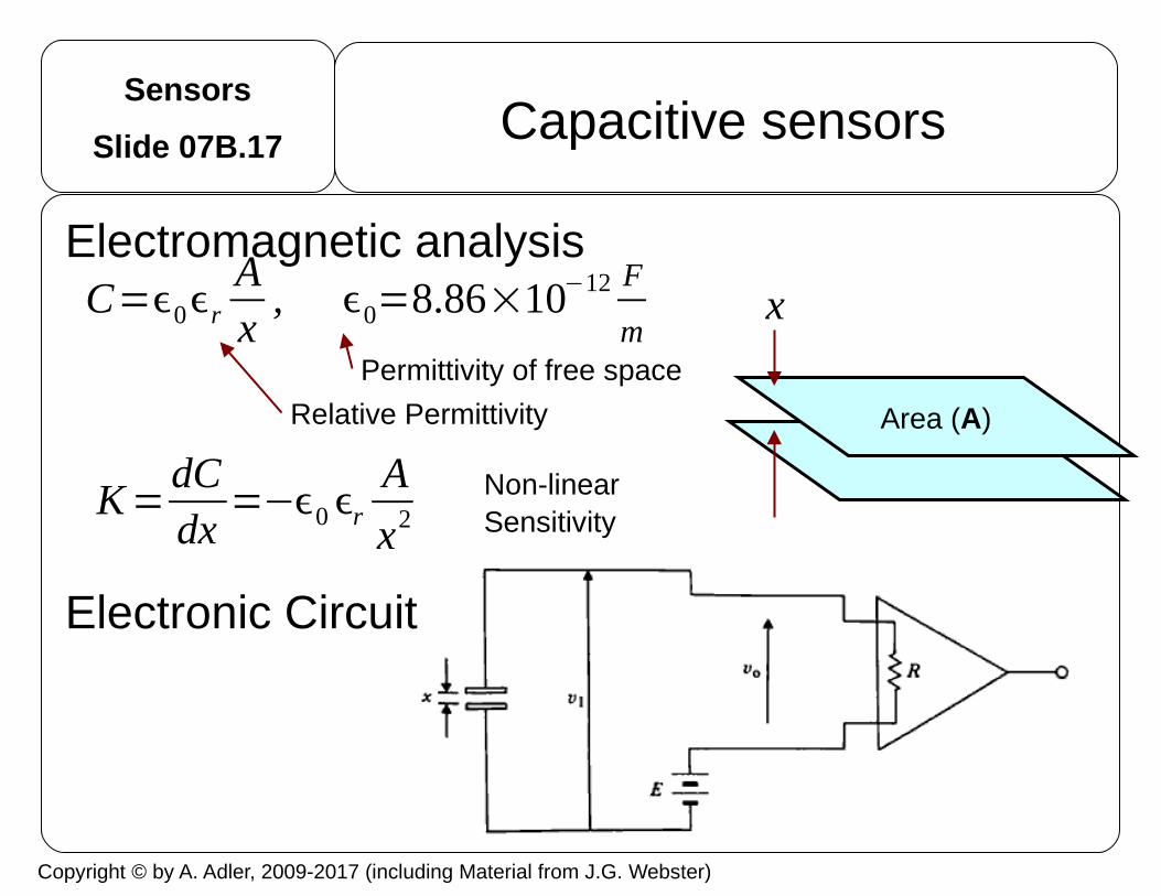
Electromagnetic analysis
Electronic Circuit
Area (A)
Permittivity of free space
Relative Permittivity
Non-linearSensitivity
xC=0r
Ax
, 0=8.86×10⁻¹² F
m
K=dCdx
=−0 r
A
x2

Copyright © by A. Adler, 2009-2017 (including Material from J.G. Webster)
Sensors
Slide 07B.18Piezo-electric sensors
Piezoelectricity is the ability of some materials to generate an electric potential to applied mechanical stress.
Apply stress → Generate voltage Apply voltage → Generate stress
Piezoelectric materials Crystals (most common is quartz) certain ceramics, including bone Films (polyvinylidenechloride: PVDC)
Disadvantage Because of very high impedance, charge leaks away. Can’t be used to measure static forces

Copyright © by A. Adler, 2009-2017 (including Material from J.G. Webster)
Sensors
Slide 07B.19Piezoelectric sensors
Analysis of sensitivity
Note that most piezosensors are very stiff, so we can assume that x is constant
Example: Calculate V for 10g weight on a 1cm2 area 1mm thick quartz. k= 2.3pC/N, ε
r = 10
Relative Permittivity
q=kf q : charge
V =qC
=kfx
ϵ0 ϵr A
K=dVdf
=kx
ϵ0 ϵr A
Copyright © by A. Adler, 2009-2017 (including Material from J.G. Webster)
Sensors
Slide 07B.20Time constant of Piezosensors
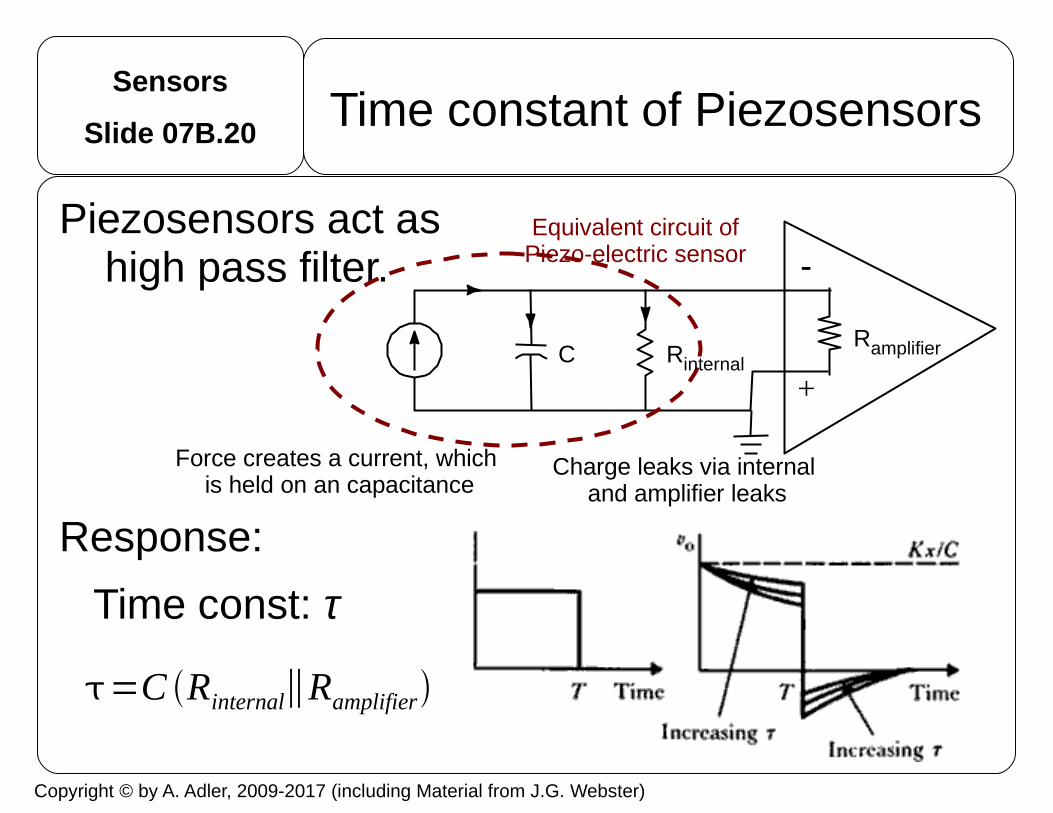
Piezosensors act as high pass filter.
Response:
Time const: τ
+
Equivalent circuit ofPiezo-electric sensor
Force creates a current, which is held on an capacitance
Charge leaks via internal and amplifier leaks
RinternalRamplifierC
=C Rinternal∥Ramplifier
Copyright © by A. Adler, 2009-2017 (including Material from J.G. Webster)
Sensors
Slide 07B.21
High freq. behaviour piezo-electric sensors
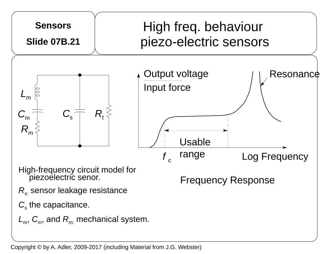
High-frequency circuit model for piezoelectric senor.
Rs: sensor leakage resistance
Cs the capacitance.
Lm, Cm, and Rm: mechanical system.
Output voltageInput force
Resonance
Log Frequency
RtCsCm
Lm
Rm
f c
Usablerange
Frequency Response
Copyright © by A. Adler, 2009-2017 (including Material from J.G. Webster)
Sensors
Slide 07B.22Questions
What is the Gauge factor? What kinds of materials have large G? When is this useful?
Why is temperature coefficient (tempco) in a strain gauge a problem? What strategies can be used to help deal with it?
Name some applications for inductive sensors?
What makes the LVDT linear, when most inductive sensors aren't?
Since capacitive sensors are highly non-linear, what kinds of applications are they useful for?
Are piezo-electric sensors linear? What are some advantages and disadvantages?

Sensors
Slide 07B.23Temperature Measurement
Why measure temperature Body is a heat engine. We burn food + oxygen to get
energy for life. Temperature monitors the functioningof the engine
Temperature increase – hyperthermia– typical cause: infection
Temperature decrease – hypothermia – typical cause: shock
Instruments Thermistors Thermocouples Radiation (hot objects emit IR radiation – not included)

Sensors
Slide 07B.24Thermistors
thermistor is a type of resistor with resistance varying according to its temperature.
thermal and resistor = thermistor Many applications for thermistors: current-
sensing, thermal protectors, self-regulating heaters.
Biomedical applications: thermometers, flow sensing, breathing (nasal thermistor)
All resistors have some temperature variation. Thermisors have large tempco (%change/ºC)
material is generally a ceramic or polymer

Sensors
Slide 07B.25Thermistor: circuit
As temperature increases, the thermistor resistance decreases, yielding more current that flows through Rf, thus Vo increases.
Many different sizes: Small Thermistors are more fragile,faster (2s) Larger Thermistors respond slowly (10s)
Offset
Thermistor
+V
–VV
0
Rf
+
–

Sensors
Slide 07B.26Thermistors
1B. (5 points) A thermistor, RT is used in the circuit below. At 35◦C, RT = 100Ω and at 36 ◦C,RT = 101Ω. What is VO for at 35◦C and 36◦C?
1C. (5 points) What is the sensitivity of at the output of the sensor, VO , in V/◦C over the rangefrom 35◦C to 36◦C?
−
+
100+10V
RT
−10V
10 kVO
+10V
−10V
The circuit is a summing inverting amplifier, whose output we can therefore write as
VO = −10 k10V
100 −10VRT
At 35◦C, RT = 100Ω and so VO = 0V, while at 36◦C, RT = 101Ω and so
VO = −10 kΩ100 Ω
1−1
1.01(10V) =−9.90V
from which the sensitivity is seen to be −9.90 V/◦C.
Midterm#2 2016
Sensors
Slide 07B.27
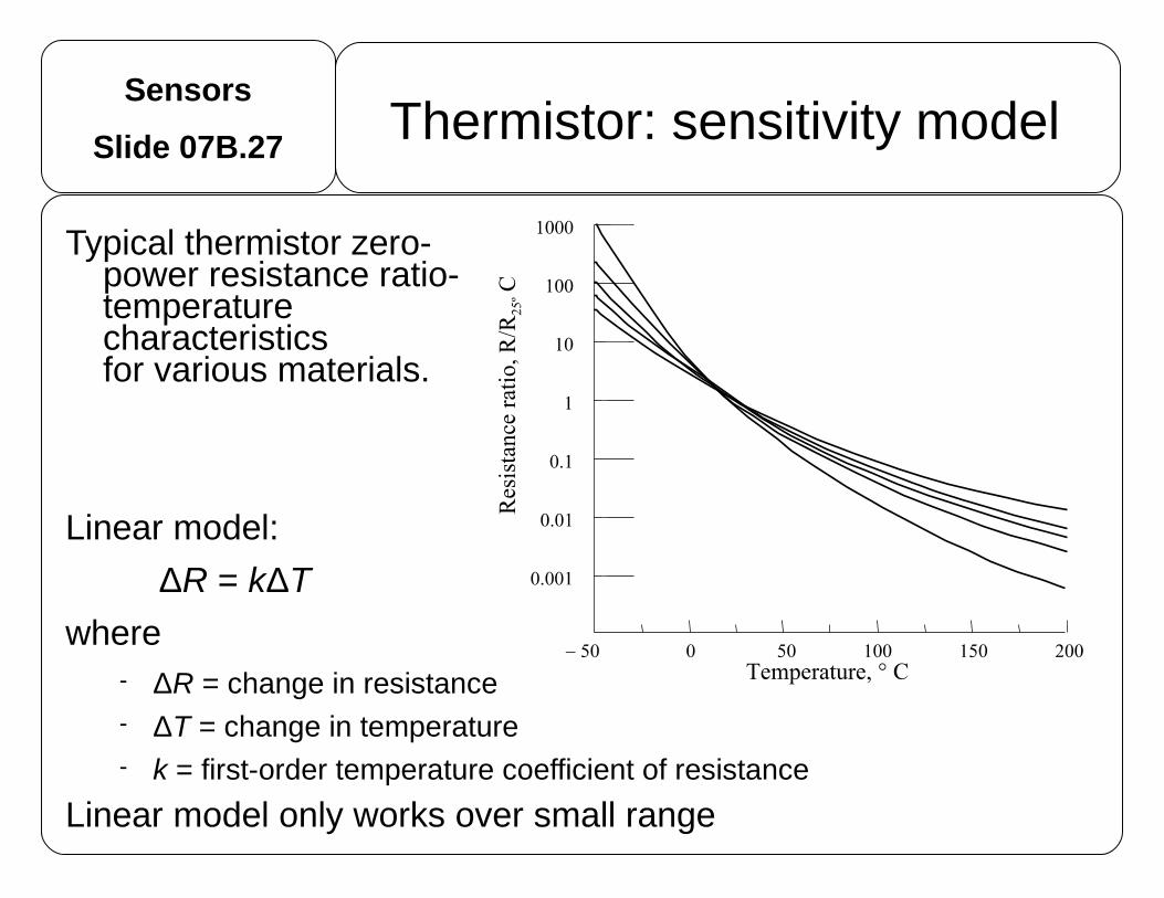
Typical thermistor zero-power resistance ratio-temperature characteristics for various materials.
Linear model:
ΔR = kΔT
where ΔR = change in resistance ΔT = change in temperature k = first-order temperature coefficient of resistance
Linear model only works over small range
Thermistor: sensitivity model

Sensors
Slide 07B.28Thermocouples
Based on Seebeck effect: when a conductor (such as a metal) is subjected to a thermal gradient, it will generate a voltage.
Thermocouples measure the temperature difference, not absolute temperature.
Traditionally, one of the junctions—the cold junction—was maintained at a known (reference) temperature, while the other end was attached to a probe.
Thermocouples are faster, smaller, more robust, more linear than thermistors
Source: Omega.com

Sensors
Slide 07B.29Thermocouples: Usage
−
+
The hot junction is at the thermocouple. The LT1025 electronic cold junction compensates for ambient temperature changes. The noninverting amplifier provides a high input impedance and high gain.
Type K (chromel–alumel) commonly used general purpose thermocouple. Inexpensive. Available in the −200°C to +1350°C range. Sensitivity ≈ 41 µV/°C.
Ri
Rf
COffset C
LT1025
Thermocouple
– +
V0
±V
+V

Sensors
Slide 07B.30Questions
Thermocouple or thermistor? Cheap Mechanically strong Simplest electrical circuit Capable of high temperatures Fastest response
Which has the highest sensitivity (V/ºC) at 50ºC Type K thermocouple Thermistor with constant current of 1mA. R0= 1kΩ. Β=
4000K.
Sensors
Slide 07B.31Questions
How does a thermistor differ from a thermocouple? Which is more linear? Which is less brittle? Which can have the fastest response?
What would you build the temperature cut-off switch in a computer from?
Why does a thermocouple need a reference circuit?
What strategies are used to help reduce drift in radiation thermal detectors?