Embed Size (px)
Citation preview

Author’s Name Name of the Paper Session
PDynamic Positioning Committee
Marine Technology Society
DYNAMIC POSITIONING CONFERENCE September 18-19, 2001
DRIVES SESSION
New Thruster Concept for Station Keeping and Electric Propulsion
Alf Kå re Ådnanes
ABB AS Marine, Oslo, Norway
Jari Ylitalo
ABB Azipod Oy, Helsinki, Finland
Dynamic Positioning Conference 2001 Page 1 of 8
New Thruster Concept for Station Keeping and Electric Propulsion
Jari Ylitalo Alf Kåre ÅdnanesABB Azipod Oy ABB AS, MarineHelsinki, Finland Oslo, Norway
AbstractAfter 10 years and 300 thousands operation hours of experi-ence with AzipodÒ for propulsion and dynamic positioning,the Compact AzipodÒ has been developed to meet the marketdemand for podded thruster units in the power range of 0.4to 5MW. High reliability, power efficiency, and life cyclecost efficiency has been the target for this new thruster con-cept for station keeping and propulsion.
IntroductionThe era of podded propulsion initiated in the late 1980’s,where a group of innovative engineers in the shipbuildingindustry and demanding ship owners outlined the Azipodpropulsion concept initially for ice going vessels, in order toimprove the reliability, efficiency, and maneuverability ofthe vessel.
Due to the mechanically simple and rugged design, superiorhydrodynamic efficiency, and maneuverability, the poddedpropulsion concept soon obtained a wide application range.It has been used as main propulsion in a number of differentship types with diesel electric propulsion, including offshoresupply vessels, tankers, and passenger vessels. For largercruise ships, it has become the state-of-the art propulsionconcept during the recent years.
As the conventional Azipod concept aims for applicationswith higher propulsion powers, mainly above 5MW per unit,even though produced as small as 600kW, it is advantageousto keep the concept as a project specific engineered unit,adaptable to the particulars of the project. This approach hasproven to be the optimal for higher propulsion powers,where minor details in the optimization may give huge bene-fits during operation.
In the propulsion market of 400kW to 5000kW, other crite-ria apply for the evaluations, and it was shown necessary toimprove the podded propulsion concept with regards tooverall cost efficiency, delivery times and off-the shelfspares availability.
A new design of a compact Azipod has been accomplished,where the aim has been to make the Azipod concept avail-able for lower power applications, by introducing a modular,and highly standardized solution.
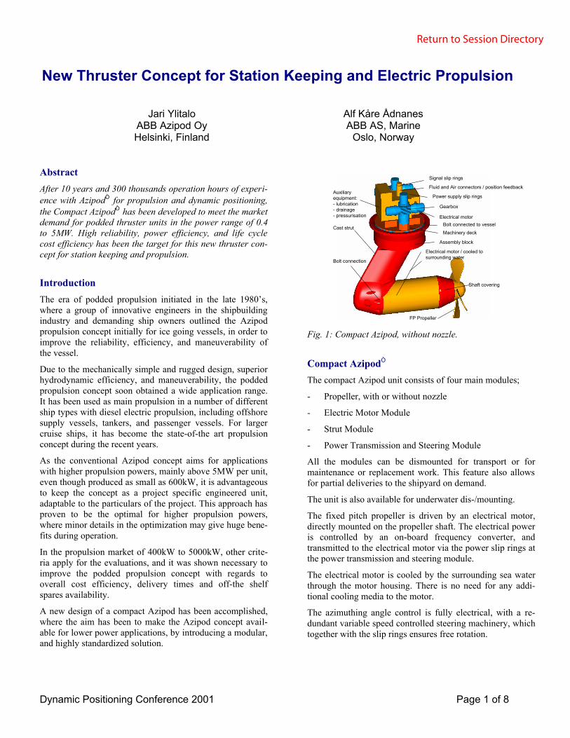
Shaftcovering
Castedframe
Cast strut
Bolt connection
Electrical motor / cooled tosurrounding water
FP Propeller
Assembly block
Bolt connected to vessel
Auxiliaryequipment:- lubrication- drainage- pressurisation
Signal slip rings
Fluid and Air connectors / position feedback
Power supply slip rings
Gearbox
Electrical motor
Machinery deck
Shaft covering
Fig. 1: Compact Azipod, without nozzle.
Compact AzipodÒ
The compact Azipod unit consists of four main modules;
- Propeller, with or without nozzle
- Electric Motor Module
- Strut Module
- Power Transmission and Steering Module
All the modules can be dismounted for transport or formaintenance or replacement work. This feature also allowsfor partial deliveries to the shipyard on demand.
The unit is also available for underwater dis-/mounting.
The fixed pitch propeller is driven by an electrical motor,directly mounted on the propeller shaft. The electrical poweris controlled by an on-board frequency converter, andtransmitted to the electrical motor via the power slip rings atthe power transmission and steering module.
The electrical motor is cooled by the surrounding sea waterthrough the motor housing. There is no need for any addi-tional cooling media to the motor.
The azimuthing angle control is fully electrical, with a re-dundant variable speed controlled steering machinery, whichtogether with the slip rings ensures free rotation.
Return to Session Directory

Dynamic Positioning Conference 2001 Page 2 of 8
1000
2000
3000
-550 -450 -350 -250 -150 -50 50 150 250 350 450 550
[astern = -RPM] n [forward = +RPM]
1-5 Single motor, 1d-5d Dual motor construction
1
2
3
4
5
0
6
Power [kW]
Fig.2: The compact Azipod is a highly modular concept,covering a range of thrust and power capacities.
The motivations for this development has been to produce apodded thruster solution, attractive for station keepingthrusters and main propulsion, by taking advantage of theexperience from the larger Azipods. This has result in aoverall cost efficient solution, with advantageous technicalcharacteristics, including:
- Two shaft bearing systems only, in contrast to minimumsix in a similar mechanical thruster
- No gear and minimized mechanical transmission losses
- Excellent hydrodynamic efficiency of propeller withuniform wake field
- No shaft alignment during assembly and installation,simplifies the construction and installation work
- Minimum amount of oil consumption, electrical steering
- No oil filters, pumps and oil cooling units
- No foundations needed besides thruster well
- High and accurate torque and power capability, reverseand forward rotation, improves the station keeping ca-pability and allows for better utilization of installedpower generation capacity
- Simple and rigid mechanical structure, with a mini-mized amount of moveable parts, gives less mainte-nance
- Higher overall efficiency, reduced power and fuel con-sumption
Propeller ModuleVarious alternatives for propeller design are possible for thecompact Azipod unit, optimized for the specific application.The propeller is normally of monoblock type.
The unit can be equipped with nozzle for increased bollardpull, Figure 3, required for thrusters in dynamically posi-tioned vessels.
Motor module
Strut module
Nozzle
Power Transmissionand Steering Module
Fig.3: Compact Azipod thruster with nozzle.
It is a well known trade-off in the design that a nozzle in-creases the hydrodynamic resistance for transit speeds, typi-cally as shown in Figure 4.
0
0,2
0,4
0,6
0,8
1
1,2
1,4
1,6
0 2 4 6 8 10 12 14 16
Vs [kts]
Thru
st/B
olla
rd th
rust
with nozzle
without nozzle
Fig 4: Typical thrust vs. speed curve,with and without nozzle.
Motor Module
- GeneralThe Compact Azipod incorporates a permanent magnet syn-chronous motor with a fixed-pitch propeller that is mounteddirectly onto the motor shaft. Permanent magnet technologygives the system a number of benefits. The outer diameter ofthe pod can be decreased, which improves hydrodynamicefficiency. The uniform frame design enables the motor tobe directly cooled via convection to the surrounding sea-water without using any additional cooling media.
- Stator Windings and InsulationThe waterproof low voltage stator winding design combinesthe class F insulation system (according to IEC) with vac-uum-pressure impregnation (VPI). The insulation techniquewas introduced already more than 20 years ago and it hasgained world-wide reputation for high reliability.
Return to Session Directory

Dynamic Positioning Conference 2001 Page 3 of 8
The insulation system exceeds the requirements of thermalclass F with good margin (average temperature limit of classF is 145 °C) which provides a good overload margin. Thestator winding also withstands well the influence of highhumidity, moisture and chemically aggressive substances.This is achieved by;
- Form-wound windings similar to high-voltage wind-ings. Form-wound winding ensures that the voltagestresses due to non-sinusoidal supply voltage remain atwell acceptable level in all winding elements.
- Before VPI, each coil is impulse voltage tested for turninsulation and DC or AC voltage tested for main insula-tion. Each coil complies with the IEC requirements forbasic impulse voltage levels.
- The wound stator including coil end bracing is impreg-nated with epoxy resin as a complete unit in the totalVPI impregnation process. High vacuum before im-pregnation and the carefully controlled process ensurethe high quality of the windings.
- The total impregnated stator winding is extremelystrong. Coil end deformations during starts and evenduring rapid breaker re-closures are avoided. Any coilvibrations in the slots are eliminated due to tight fit.
- Permanent Magnet RotorThe salient pole permanent magnet rotor consists of a shaft,a hub, permanent magnets and pole shoes. The hub is shrinkfitted onto the shaft and the permanent magnets are me-chanically locked to the hub. The whole rotor is in conclu-sion impregnated.
The rotor excitation is generated by permanent magnets.Thus it does not have any electric connections to the rotor.
Permanent magnet material is selected based on the me-chanical, thermal, magnetic and corrosive requirements ofCompact Azipod components.
- BearingThe lubrication of the compact Azipod is provided from aprogrammable lubrication unit, Figure 5. The grease lubri-cation unit is located in the Azipod room and it is equippedwith alarms for low level of lubricant and pump malfunc-tion.
Grease lubrication is very suitable for propeller side bearingload and environmental conditions. Needed lifetime volumeof grease is very small due to effective cooling, whichmakes it possible to dimension the waste grease chamber forthe bearing lifetime. There is no need for oil change.
Fig. 5: Bearing lubrication.
Thrust bearing of Compact Azipod is oil sump lubricatedanti friction (rolling) bearing, which is directly cooled tosurrounding water. The bearing does not have any sealsagainst water, which gives maximum protection against wa-ter.
Because of effective cooling it does not need any oil circuit.Therefore any filters are neither needed.
- Shaft SealingLubrication is very sensitive against water, e.g. water con-tent above 0,03-0,05 % starts to decrease oil lifetime signifi-cantly. Therefore the shaft sealing is carefully designed toavoid any water penetration to the bearing. Shaft sealing is acombination of water lubricated face seal and two greaselubricated lips seals. The outermost seal is water lubricated,which is important for achieving zero emissions to the envi-ronment.
Face seal is made of ceramic material and it acts as mainseal. Thus two lips seals can handle the sealing function alsoalone.
- Bilge Water ControlThe compact Azipod is equipped with bilge drainage andleakage control system, which enables follow-up of thestatus of the sealing of the motor module. The concept in-cludes leakage detection and drain arrangement both be-tween the seals and inside the motor. Drainage is done bypressurizing the inside of the motor and leading the drainagepipe into atmospheric pressure in the Azipod room.
This system consists of compressed air sources, piping andsight glass, shown in Figure 6.
Return to Session Directory

Dynamic Positioning Conference 2001 Page 4 of 8
Fig. 6: Pressurizing and bilge control.
This system also gives a small overpressure relative to thesurrounding water, hence reducing the risk of water penetra-tion to the bearing housing and motor module.
- Underwater Dismounting and MountingThe compact Azipod has been designed for underwater dis-/mounting.
The basic design criteria has been that all underwater han-dling should be ROV enabled without diver support. An-other basic design criteria have been that whole underwateroperation must be possible to carry out with one crane only.
Before mounting, the compact Azipod unit is equipped witha water tight protection doom and pressurized. Hull guideframe cover are watertightly assembled in the pontoon
In the first phase the Azipod is lowered with one main wirerope. Eventually, the whole weight of Azipod will be carriedby three guiding wires.
In the second stage the crane-hook is moved to a spreaderwhere guide wires are connected and the Azipod is lifted upinto final guiding place. The positioning is ensured by aconical guiding ring for the coarse guiding and mini postsfor the final positioning, as illustrated in Figure 7. Lockedwater between Azipod and hull-guide frame cover are re-moved by pressurized air.
Bolts are tightened from inside of the pontoon. Finally allwires are disconnected by ROV and the in-hull equipmentcan be assembled and connected.
The dismounting procedure is in principle the same, but inreverse order.
Fig. 7: Principle sketch of the means for position guidingwhen underwater mounting.
Strut ModuleStrut module acts as a connective element in CompactAzipod structure. Control cables, piping and power supplybus bars for propulsion motor are located inside the one-piece cast strut module.
The shape of the strut module is designed to minimize hy-drodynamic losses and yet to give a rudder effect withoutrunning propeller during voyage.
Power Transmission and Steering ModuleThe power transmission and steering module consists oflocal control and equipment box, slip-ring unit (cable drumas an option), steering motors with gearboxes and assemblyblock. This module is located inside the hull of the vessel.
The azimuth steering is electrical, with a redundant electricmotor drive system, controlled by variable speed controllersfor soft and precise azimuth control, without hydraulicpower transmission.
The assembly block is a rigid self-supporting structure in-corporating slewing bearing and slewing gear ring and seal-ing against surrounding water. This design enables assemblyand factory acceptance tests for the whole unit includingsteering and power transmission units.
The assembly block is sealed against surrounding water withstatic seal. The rotating tiller is sealed against assemblyblock with lip seals.
Return to Session Directory

Dynamic Positioning Conference 2001 Page 5 of 8
Drive SystemThe Compact Azipod propulsion system includes anACW600 water-cooled propulsion drive. The low voltagefrequency converter is supplied from the main switchboardor via a supply transformer. The ACW600 converts the ACvoltage to required output using Direct Torque Control(DTC) principle and IGBT power semiconductor technol-ogy. The output frequency can be regulated to achieve thefull power in both directions of rotation as well as to anyrequired speed. Due to the principle of electric motor caneven full torque can be achieved even with zero speeds.
The drive and compact Azipod inherently allows for twoquadrant operation, which means full torque in positive andnegative direction of rotation. For quicker speed variations,or regenerative breaking during transit conditions, a fourquadrant capability is often required, see Figure 8. This isusually obtained by using a breaking resistor in the DC linkof the frequency converter.
Speed
Torque
P<0 P>0
P>0 P<0
Quadrant IVBreaking
Speed>0, Torque <0
Quadrant IIIMotoring
Speed<0, Torque <0
Quadrant IMotoring
Speed>0, Torque >0
Quadrant IIBreaking
Speed<0, Torque >0
Fig. 8: Two quadrant operation (P>0) is inherent in thecompact Azipod. Four quadrant operation requiresregenerative breaking.
Direct Torque ControlDirect Torque Control (DTC) is a unique motor controlmethod developed by ABB for AC Drives.
The inverter switching is directly controlled according to themotor core variables; flux and torque, Figure 9. The meas-ured motor current and DC link voltages are inputs to anadaptive motor model which produces exact actual values oftorque and flux every 25 microseconds. Motor torque andflux is compared to actual values to the reference valuesproduced by the torque and flux reference controllers. De-pending on the outputs from the hysteresis controllers, theoptimal switching logic directly determines the optimuminverter switch positions every 25 µs. In DTC, everyswitching is determined separately based on the instantane-
ous values of flux and torque, rather than switching in a pre-determined pattern as in conventional PWM current vectorcontrolled drives, Figure 10.
In propulsion systems, the dynamic performance of the driveis under most normal operations and conditions much betterthan the requirements. It is however, a great advantage witha high speed torque response in handling of fault situations,e.g. at a sudden drop of generator capacity where the DTCenables a quick and accurate power reduction rather than apower phase back or load shedding functionality. This fea-ture allows for implementation of a much more precise loadmanagement and black-out prevention functionality in thepower management system, allowing to utilize installed en-gine capacity at a higher level, and yet reducing the risk forunintended unavailability of the thrusters, or black-out.
The DTC utilizes a variable switching frequency rather thana fixed switching frequency, which is common for PWMconverters. The objective is to switch only when necessaryin order to increase the dynamic band with of the controlloop with minimum switching losses. As a side effect, theacoustic noise from a DTC controlled motor does not havethe distinct frequency peaks as a PWM controlled motor.The noise band is wide and rather flat, and is perceivedsimilar to a weak white noise by humans, Figure 11. Also,the lack of high noise peaks in the 15-30kHz region contrib-utes to lower risk of interference with hydro-acoustic sen-sors.
Fig. 9: DTC, block diagram.
Fig 10: Typical DTC torque step response
Return to Session Directory

Dynamic Positioning Conference 2001 Page 6 of 8
0 5 1 0 1 5 2 0 2 5F r e q u e n c y ( k H z )
D T CP W M
N o i s el e v e l
Fig 11: Typical noise spectrum from DTC and PWM drives
Compact Azipod Control SystemThe control system consists of the thruster motor controllerin the frequency converter, dual azimuth control system inthe azimuth steering converters, and local/remote manualcontrols, as shown in Figure 12.
These control functions are implemented in standard auto-mation and drive controllers of the IndustrialIT platform.This also ensures compatibility to integration with other on-board automation systems, such as power management, joy-stick controllers, and dynamic positioning systems by usingstandardized field-bus communication where this is permit-ted by rules and regulations, see Figure 13. Hardwired sig-nals are only used where necessary. The use of configurableunits and standardized communication protocols increasesthe robustness and reduces start-up times, yet maintaining ahigh degree of flexibility for adaptation to the specific vesselconfigurations.
Electronic remote control panel
Interfaces, e.g. Joystick, DP, PMS
Compact Azipod electronic control
Motor control and frequencyconverter
Azimuth control and frequencyconverter
Compact Azipod
Fieldbus communication
Fig.12 : Schematics of remote control system.
¨
Fig.13: The control system can easily be extended to an in-tegrated MTC and Joystick control system.
Compact AzipodÒ for PropulsionElectric propulsion has been used in a large number of ves-sel types for decades. Electrically driven shaft line propellershave been replaced by mechanical thrusters and Azipod pro-pulsion system, increasing the hydrodynamic efficiency andthe maneuverability of the vessels.
Figure 14 shows an example of a DP class 2-3 vessel withtwo compact Azipod propulsion units, now under construc-tion. The compact Azipods are here without nozzle in orderto increase the transit speed. Electrically driven, variablespeed tunnel thrusters and a retractable mechanical thrustersare used to obtain the DP capability and maneuverability.
The electric power generation and distribution system forthis kind of vessels is normally a two-split system, as shownin Figure 15 for the propulsion system. The number of run-ning generators are selected, manually or automatically bythe power management system, to meet the actual load de-mand with highest possible fuel efficiency. The installedsystem is therefore operating optimally under any load andoperating conditions, as shown in Figure 16.
Fig 14: Two compact Azipod units used asmain propulsion for a supply vessel /1/.
Return to Session Directory

Dynamic Positioning Conference 2001 Page 7 of 8
Vessel Loads
Propulsion Auxilliaries
Fig 15: Simplified single line diagram of the diesel electricpropulsion system in a supply vessel.
Fig. 16: Typical comparison of fuel efficiency with Azipodpropulsion vs. other propulsion systems
Fig. 17: Comparison of fuel oil consumption (FOC) for asupply vessel with Azipod propulsion and conven-tional shaft line propulsion, with varying operationprofile.
According to studies, and verified by ship owners, it hasbeen proven that there is a significant fuel cost saving, up to30% to 40% compared to conventional mechanical shaftlines, depending on the operational profile. Figure 17 showshow the fuel saving increases with the share of stationkeeping and maneuvering for a calculated example.
As a main propulsion unit, the compact Azipod can beequipped with or without nozzle for optimizing the bollardpull and transit speed requirements. The nozzle will alsoinfluence the free-wheeling steering capability, which for acompact Azipod can be made quite efficient with the rudder-shaped strut module.
Mounting and dismounting of the propulsion unit may nor-mally take place under dry conditions, by un-ballasting thevessel, or in dry dock. Where a dry dis-/ mounting is accept-able, the strut can be dismounted from the power transmis-sion and steering module in a flanged connection.
As a main propulsion unit for supply vessels, it is normallynecessary to keep the dimensions and height of the equip-ment smallest possible. The space in the aft section under-neath deck, normally is very restricted, as shown in Figure18.
Fig. 18: Example propulsion machinery arrangementfor a supply vessel.
Return to Session Directory
Dynamic Positioning Conference 2001 Page 8 of 8
Compact AzipodÒ for Station KeepingFor installations where station keeping capability is the mostimportant characteristic, and transit speed and efficiency areof less importance, other criteria for design optimization ofthe compact Azipod applies.
As thruster unit for dynamic positioning and maneuvering,the compact Azipod will normally be equipped with nozzlefor optimizing the bollard pull capability. As illustrated inFigure 4, bollard pull can be increased with typically closeto 40% of what can be achieved without nozzle. In typicalapplications, like semisubmersible drilling units, Figure 19,and drill ships, it is a normally acceptable trade-off with areduced efficiency and transit speed.
The compact Azipod can inherently operate in both directionof rotation, with full torque and power, due to the gear-lessshaft line and also since the thrust bearing is capable of ab-sorbing full thrust in each direction. It has been shown thatthis feature in some applications can reduce the amount ofmargins for dynamic thruster usage, and hence increase thevessel’s station keeping capability. Optimization of the pro-peller and nozzle may, however, reduce the obtainable thrustin negative rotation, and the effects on the vessel’s capabilitymust be evaluated in each case.
Where thruster units are located close to each other, it isdesired to reduce the thruster-thruster interaction. In suchinstallations, the compact Azipod system may be configuredwith forbidden sectors, or sectors with reduced thrust usage.
Fig. 19: Schematics of a semi-submersible drilling rig withcompact Azipod thrusters for dynamic positioningand propulsion.
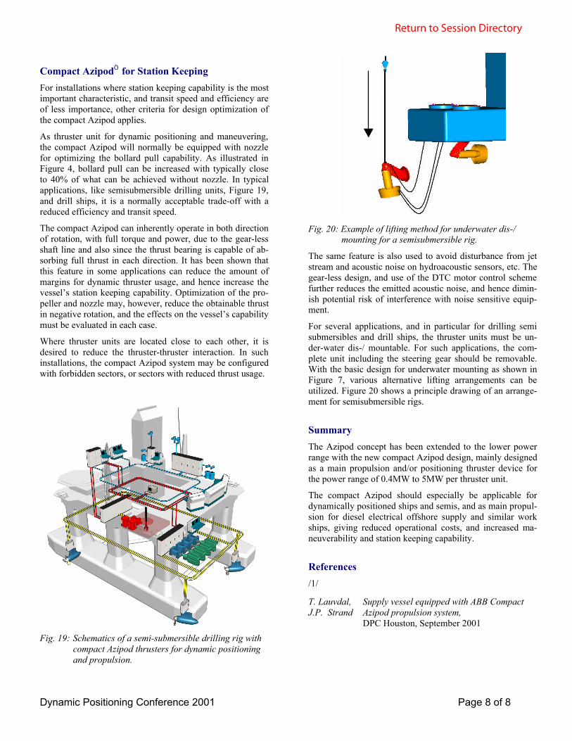
Fig. 20: Example of lifting method for underwater dis-/mounting for a semisubmersible rig.
The same feature is also used to avoid disturbance from jetstream and acoustic noise on hydroacoustic sensors, etc. Thegear-less design, and use of the DTC motor control schemefurther reduces the emitted acoustic noise, and hence dimin-ish potential risk of interference with noise sensitive equip-ment.
For several applications, and in particular for drilling semisubmersibles and drill ships, the thruster units must be un-der-water dis-/ mountable. For such applications, the com-plete unit including the steering gear should be removable.With the basic design for underwater mounting as shown inFigure 7, various alternative lifting arrangements can beutilized. Figure 20 shows a principle drawing of an arrange-ment for semisubmersible rigs.
SummaryThe Azipod concept has been extended to the lower powerrange with the new compact Azipod design, mainly designedas a main propulsion and/or positioning thruster device forthe power range of 0.4MW to 5MW per thruster unit.
The compact Azipod should especially be applicable fordynamically positioned ships and semis, and as main propul-sion for diesel electrical offshore supply and similar workships, giving reduced operational costs, and increased ma-neuverability and station keeping capability.
References/1/
T. Lauvdal,J.P. Strand
Supply vessel equipped with ABB CompactAzipod propulsion system,DPC Houston, September 2001
Return to Session Directory


