Embed Size (px)
Citation preview

D R . T A R E K A . T U T U N J I
P H I L A D E L P H I A U N I V E R S I T Y , J O R D A N
2 0 1 3
Sensors and Transducers: Overview

Introduction
A sensor is defined as a device that produces an output signal for the purpose of sensing of a physical phenomenon.
Sensors are also referred to as transducers.
A transducer is defined as a device that converts a signal from one physical form to a corresponding signal, which has a different physical form.

Mechatronics Measurement System
[Ref.] Shetty

General Instrumentation System
[Ref.] Shetty

Sensor Classification
[Ref.] Shetty
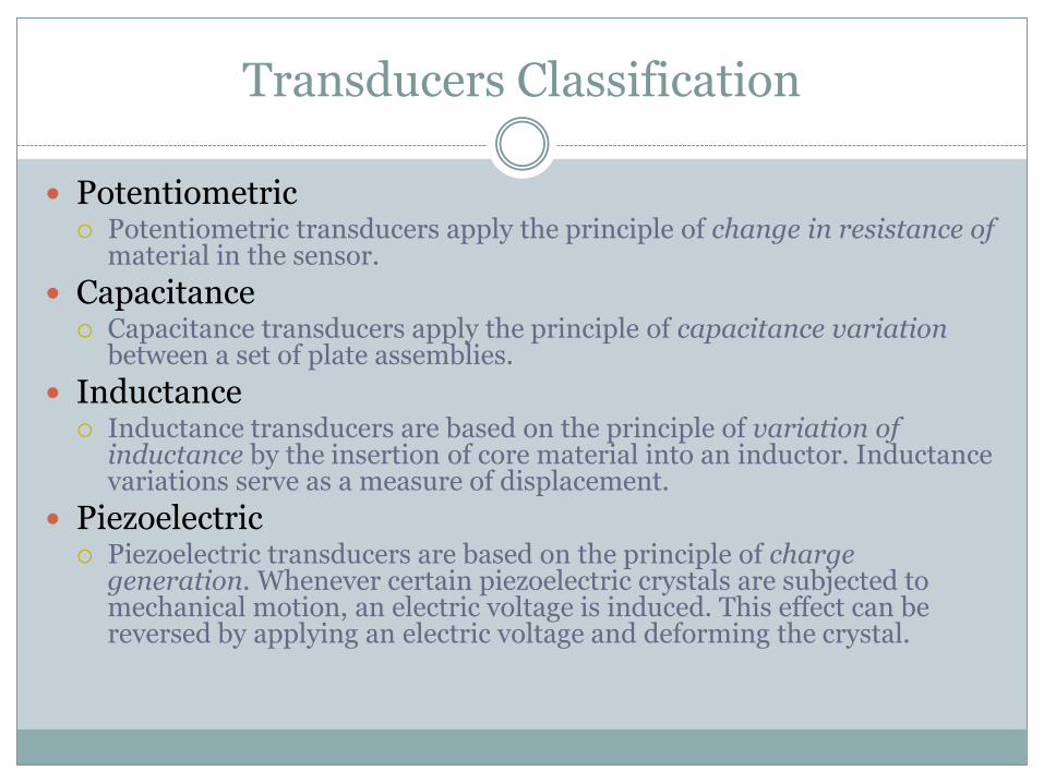
Transducers Classification
Potentiometric Potentiometric transducers apply the principle of change in resistance of
material in the sensor.
Capacitance Capacitance transducers apply the principle of capacitance variation
between a set of plate assemblies.
Inductance Inductance transducers are based on the principle of variation of
inductance by the insertion of core material into an inductor. Inductance variations serve as a measure of displacement.
Piezoelectric Piezoelectric transducers are based on the principle of charge
generation. Whenever certain piezoelectric crystals are subjected to mechanical motion, an electric voltage is induced. This effect can be reversed by applying an electric voltage and deforming the crystal.

Elements of Instrumentation System
[Ref.] Shetty

Home Heating System Example
[Ref.] Shetty

Quality Parameters
Sensitivity
Resolution
Accuracy
Precision
Backlash
Repeatability
Linearity
Linear and Rotational Sensors
Linear and rotational position sensors are two of the most fundamental of all measurements used in a typical mechatronics system.
Position sensors produce an electrical output that is proportional to the displacement.
Contact: Strain gage, LVDT, RVDT, and tachometer.
Noncontact : encoders, hall effect, capacitance, and inductance.

Linear and Rotational Sensors
Hall effect, fiber, optic inductance, capacitance, and strain gage are considered high resolution sensors, but suitable for only very small range (typically from 0.1 mm to 5 mm).
The differential transformers on the other hand, have a much larger range with good resolution.
Among many linear displacement sensors, strain gage provides high resolution at low noise level and is least expensive.

Potentiometer
[Ref.] Kilian + Shetty

Potentiometer as Position Sensor
[Ref.] Kilian

Potentiometers Features and Applications
Features Linear potentiometers are often considered when an electrical
signal proportional to displacement is required, but also where cost should be kept low and high accuracy is not critical.
Typical rotary potentiometers have a range of +-170°. Their linearity varies from 0.01 to 1.5%.
Applications Used for position monitoring of products on assembly lines
and checking dimensions of the product in quality control systems.
Rotary potentiometers are used in applications involving rotational measurement for applications ranging from machine tools to aircraft.

Linear Variable Displacement Transformer (LVDT)
[Ref.] Kilian

Linear Variable Displacement Transformer (LVDT)
[Ref.] Kilian

LVDT Interface Circuit
[Ref.] Kilian

LVDT Features and Applications
Features: High resolution, high accuracy, and good stability make them an ideal
for applications involving short displacement measurements. Sensitive transducers provide resolution down to about 0.05 mm. They
have operating ranges from about 0.1 to 300 mm. Accuracy is 0.5 mm of full-scale reading. Less sensitive to wide ranges in temperature than potentiometers.
Applications Measurement of precision gap between weld torch and work surface in
welding applications. Measurement of the thickness of plates in rolling mills. Detection of surface irregularity of parts after they are machined.
Angular speed measurement of a rotating device. Precise detection of specimen size. Liquid level applications.

Rotary Encoders Applications
Encoders are used for measurement of linear or angular position, velocity, and direction of movement.
Used in computerized manufacturing machines, motion-control applications, and quality assurance of equipment.
Used in tensile-test instruments to precisely measure the ball screw position.
Used in automated test stands used when angular positions of windshield wiper drives and switch positions are tested.
Incremental encoders commonly are used for counting applications.

Optical Encoding: Absolute
[Ref.] Kilian

Optical Encoding: Incremental
[Ref.] Kilian

Encoder Interface Circuit
[Ref.] Kilian

Tachometer
[Ref.] Kilian

Tachometer Example

Acceleration Sensors
Measurement of acceleration is important for systems subject to shock and vibration.
Seismic mass
The seismic mass type accelerometer is based on the relative motion between a mass and the supporting structure. The natural frequency of the seismic mass limits its use to low to medium frequency applications.
Piezoelectric accelerometer.
The piezoelectric accelerometer, however, is compact and more suitable for high frequency applications

Vibration Sensors: Seismic Mass

Vibration Sensors: Piezoelectric
[Ref.] Shetty

Force, Torque, and Pressure Sensors
Common force/torque sensors are: strain gauge and piezoelectric.
Both are available to measure force and/or torque either in
one axis or multiple axes.
The strain gauge make use of mechanical members that experiences elastic deflection when loaded. These types of sensors are limited by their natural frequency.
The piezoelectric sensors are particularly suitable for dynamic
loadings in a wide range of frequencies. They provide high stiffness, high resolution over a wide measurement range, and are compact.

Strain Gauges
[Ref.] Shetty
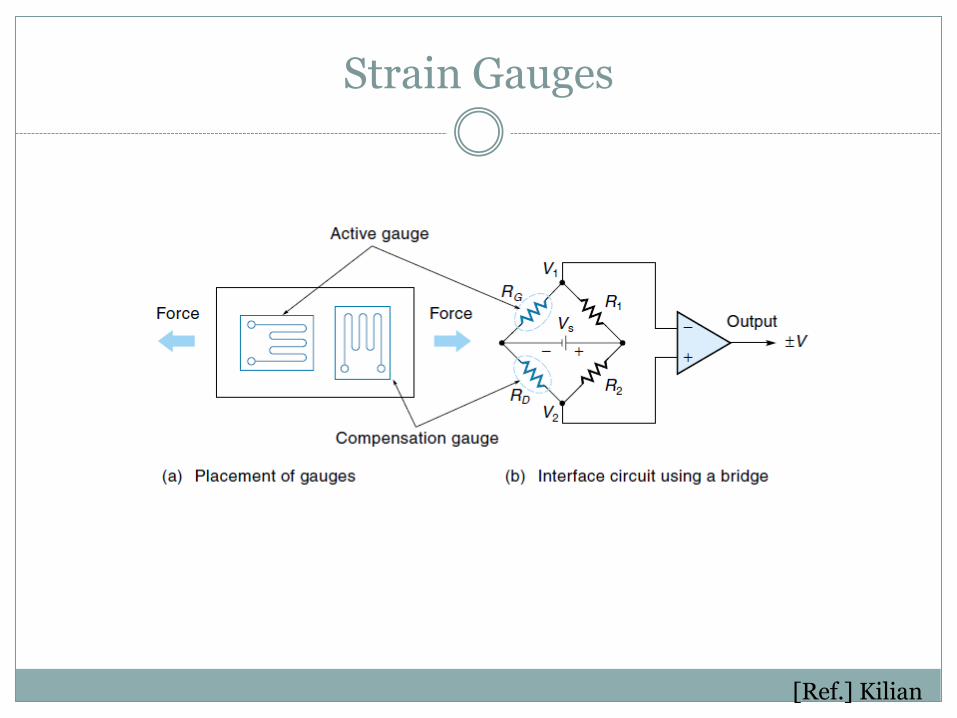
Strain Gauges
[Ref.] Kilian

Load Cells
[Ref.] Kilian

Strain Gauges
Features A high gauge factor increases its sensitivity and causes a larger change in
resistance for a particular strain. High resistance of the strain gauge minimizes the effect of resistance
variation in the signal processing circuitry. Choose gauge characteristics such that resistance is a linear function of strain.
For dynamic measurements, the linearity should be maintained over the desired frequency range.
Low temperature coefficient and absence of the hysteresis effect add to the precision.
Applications Strain-gauge transducers are used for measuring strain, force, torque,
pressure, and vibration. In some applications, strain gauges are used as a primary or secondary
sensor in combination with other sensors.

Tactical Force Sensor
[Ref.] Kilian

Conductive Foam Tactical Sensor
[Ref.] Kilian
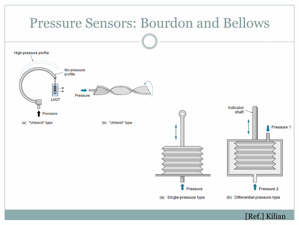
Pressure Sensors: Bourdon and Bellows
[Ref.] Kilian

Semiconductor Pressure Sensor
[Ref.] Kilian

Flow Sensors
The fluid medium can be liquid, gas, or a mixture of the two. The flow could be laminar or turbulent and can be a time-
varying phenomenon. The venturi meter and orifice plate restrict the flow and use
the pressure difference to determine the flow rate. The rotameter and the turbine meters when placed in the
flow path, rotate at a speed proportional to the flowrate. The electromagnetic flow meters use noncontact method.
Magnetic field is applied in the transverse direction of the flow and the fluid acts as the conductor to induce voltage proportional to the flow rate.

Flow Sensors
Ultrasonic flow meters measure fluid velocity by passing high-frequency sound waves through fluid. Transmitters (T) provide the sound signal source. As the wave travels
towards the receivers (R), its velocity is influenced by the velocity of the fluid flow due to the doppler effect.
The control circuit compares the time to interpret the flow rate. This can be used for very high flow rates and can also be used for both upstream and downstream flow. The other advantage is that it can be used for corrosive fluids, fluids with abrasive particles, as it is like a noncontact sensor.

Orifice Plate and Venturi Flow
[Ref.] Kilian
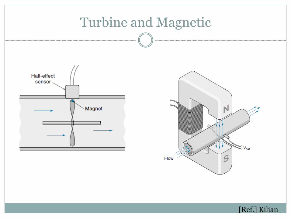
Turbine and Magnetic
[Ref.] Kilian
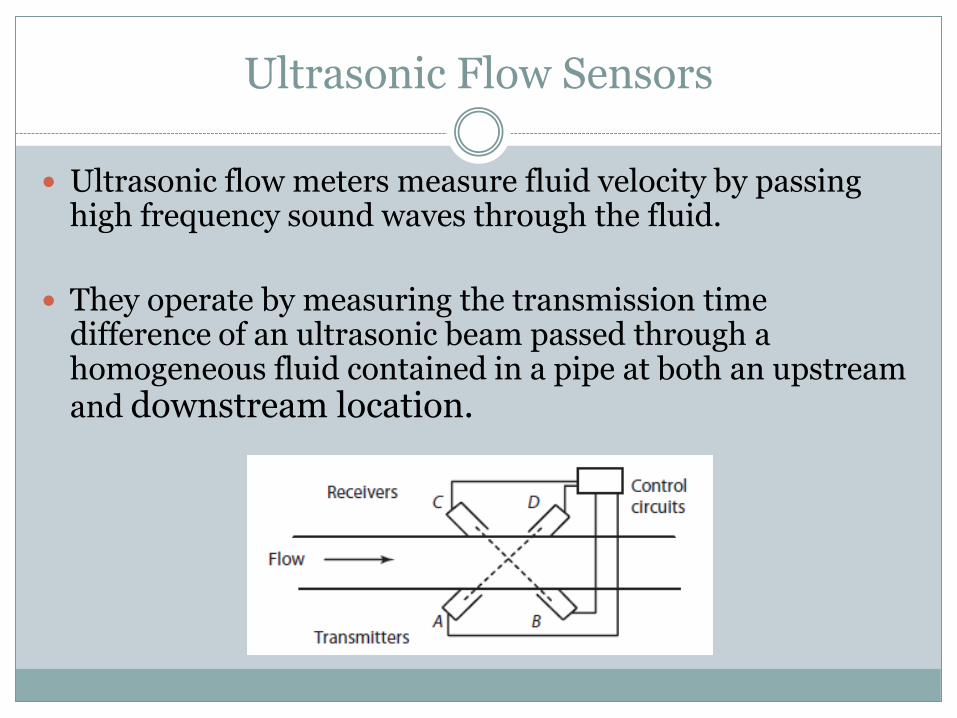
Ultrasonic Flow Sensors
Ultrasonic flow meters measure fluid velocity by passing high frequency sound waves through the fluid.
They operate by measuring the transmission time difference of an ultrasonic beam passed through a homogeneous fluid contained in a pipe at both an upstream and downstream location.

Flow Sensors for Solids

Level Sensors
Level sensors are used to measure the fluid level in tanks.
There are discrete and continuous level sensors

Discrete Level Sensor
[Ref.] Kilian

Continuous Level Sensor
[Ref.] Kilian

Temperature Sensors
The most common temperature sensors are: Thermocouples Thermisters Resistance Temperature Detectors (RTD) Infrared types.
Thermocouples are the most versatile, inexpensive, and
have a wide range (up to 1200 C typical). A thermocouple simply consists of two dissimilar metal wires joined at the ends to create the sensing junction. When used in conjunction with a reference junction, the temperature difference between the reference junction and the actual temperature shows up as a voltage potential.

Temperature Sensors
Thermistors are semiconductor devices whose resistance changes as the temperature changes. They are good for very high sensitivity measurements in a limited range of up to 100 C. The relationship between the temperature and the resistance is nonlinear.
The RTDs use the phenomenon that the resistance of a metal
changes with temperature. They are, however, linear over a wide range and most stable
Infrared type sensors use the radiation heat to sense the
temperature from a distance. These noncontact sensors can also be used to sense a field of vision to generate a thermal map of a surface

Temperature Sensors
Temperature measurement is based on one of the following principles.
1. Material expansion based on change in length, volume, or pressure.
2. Based on the change in electrical resistance.
3. Based on contact voltage between two dissimilar metals.
4. Based on changes in radiated energy.

Thermocouple
[Ref.] Kilian

Thermocouple Chart

Standard Thermocouple Characteristics
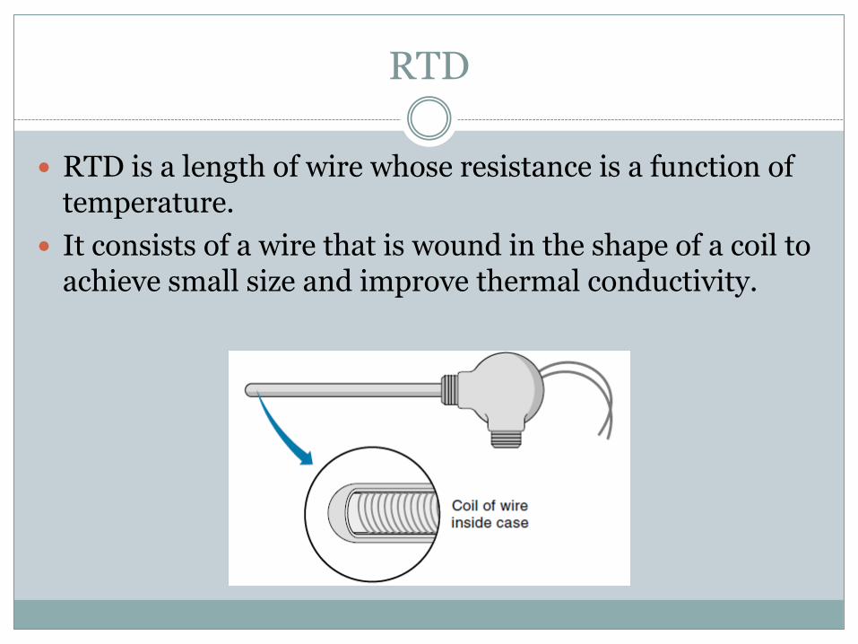
RTD
RTD is a length of wire whose resistance is a function of temperature.
It consists of a wire that is wound in the shape of a coil to achieve small size and improve thermal conductivity.

Thermistor
[Ref.] Kilian
Thermistor operation relies on the principle of change in semiconductor resistance with change in temperature

LM35 Temperature Sensor

LM35 Temperature Sensor

Proximity Sensors
They are used to sense the proximity of an object relative to another object. They usually provide ON/Off signal indicating the presence or absence of an object.
Examples: Capacitance, inductance, photoelectric, and hall effect Capacitance types are similar to inductance except the proximity
of an object changes the gap and affects the capacitance.
Inductance proximity sensors consist of a coil wound around a soft iron core. The inductance of the sensor changes when a ferrous object is in its proximity. This change is converted to a voltage-triggered switch.

Capacitive Transducer
A change in capacitance can be brought about by varying the following parameters. Changing the distance between the two parallel electrodes. Changing the dielectric constant, permittivity, of dielectric medium . Changing the area of the electrodes, A.
Features Capacitance transducers can be used in high humidity, high temperature, or
nuclear radiated zones. They are very sensitive and have high resolution. They can be expensive and need
significant signal conditioners.
Applications Capacitance transducers are generally only suitable for measuring small
displacements. Examples of these are surface profile sensing, wear measurement, or crack growth.
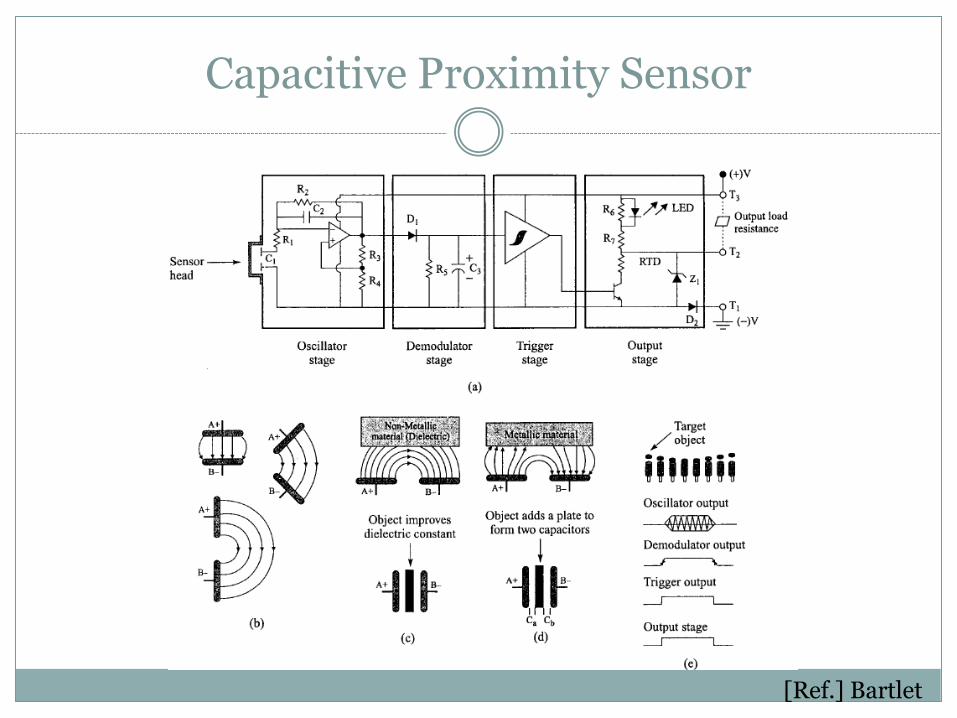
Capacitive Proximity Sensor
[Ref.] Bartlet

Inductive Proximity Sensor
[Ref.] Bartlet

Proximity Sensors
Photoelectric sensors are normally aligned with an infrared light source. The proximity of a moving object interrupts the light beam causing the voltage level to change.
Hall effect voltage is produced when a current-carrying conductor is exposed to a transverse magnetic field. The voltage is proportional to transverse distance between the hall effect sensor and an object in its proximity
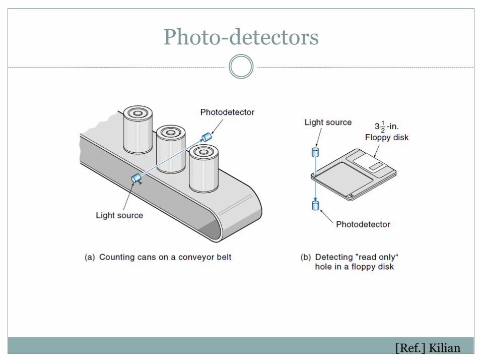
Photo-detectors
[Ref.] Kilian

Hall Effect
Hall effect transducers are used to measure position, displacement, level, and flow. They can be used as an analog motion sensing device as well as a digital device.
The Hall effect occurs when a strip of conducting material carries current in the presence of a transverse magnetic field.
An electron of charge, e, traveling in a magnetic field, B, with a
velocity v, experiences a Lorenz force F, and it is represented by F = e ( v x B)
An electric field, known as Hall’s field, counterbalances Lorenz’s
force and is represented by an electric potential. The voltage produced may be used to produce field strength or a current.

Hall Effect Sensors
[Ref.] Kilian

Light Sensors
Light intensity and full field vision are two important measurements used in many control applications.
Phototransistors, photoresistors, and photodiodes are
some of the more common type of light intensity sensors. When the photoresistor is exposed to light, its resistance
drops in proportion to the intensity of light. When interfaced with a circuit and balanced, the change in light intensity will show up as change in voltage.
These sensors are simple, reliable, and cheap, used
widely for measuring light intensity.

Light Sensors

Optical Slotted Coupler
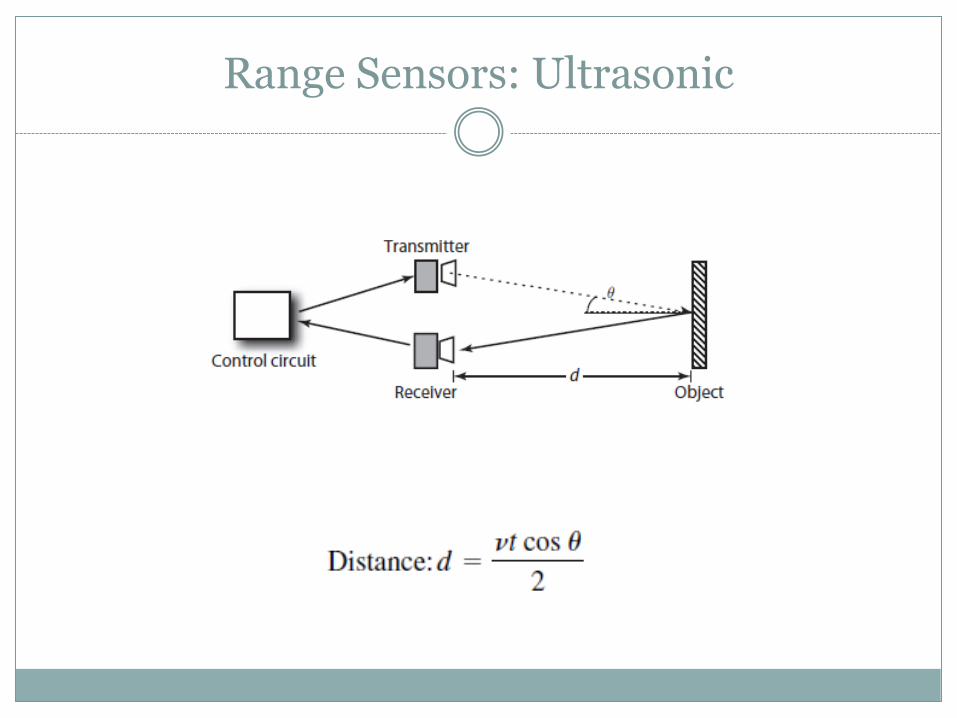
Range Sensors: Ultrasonic

Range Sensors: Laser

Smart Material Sensors
New smart materials are being used as sensors.
Examples are: Optic fibers, piezoelectric, and magnetostrictive materials
Optic fibers Can be used to sense strain, liquid level, force, and temperature with
very high resolution. They have found numerous applications in smart structure applications
such as damage sensors, vibration sensors, and cure-monitoring sensors.
The basic principle of operation of an embedded optic fiber used to sense displacement, force, or temperature. The relative change in the transmitted intensity or spectrum is proportional to the change in the sensed parameter.

Optical Fiber Sensing

Piezoelectric Transducer
Piezoelectric materials, when subjected to mechanical force or stress along specific planes, generate electric charge.
The best-known natural material is quartz crystal (SiO2).
Rochelle salt is also considered a natural piezoelectric material.
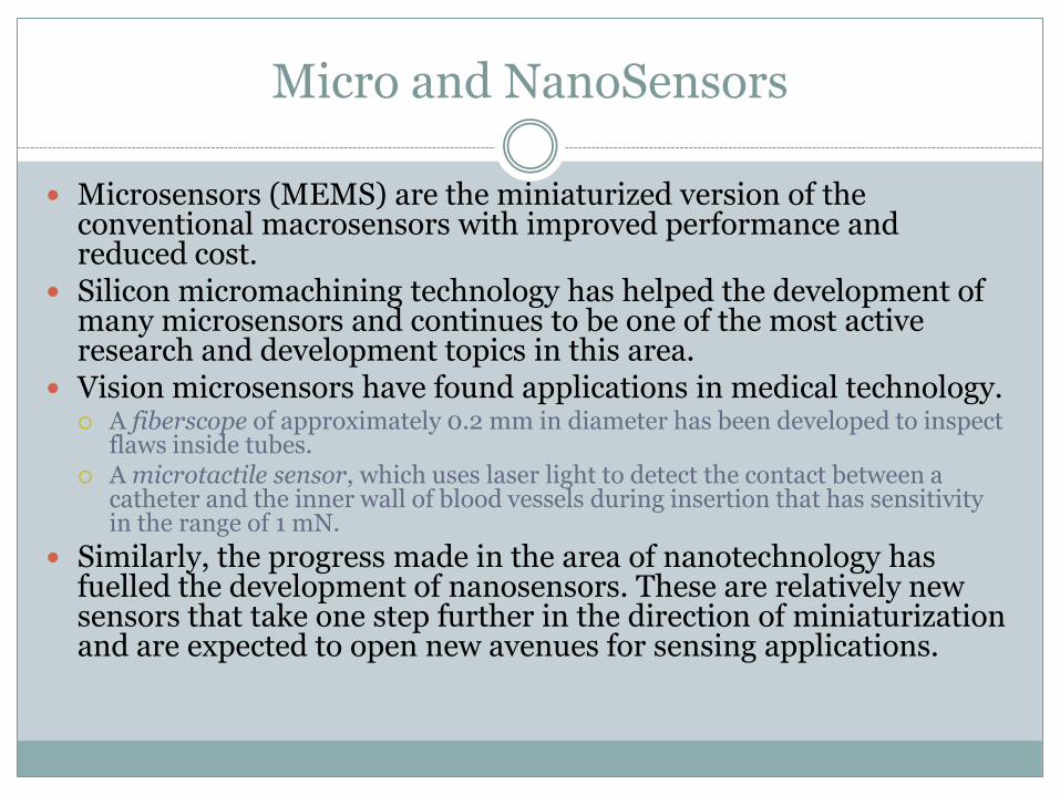
Micro and NanoSensors
Microsensors (MEMS) are the miniaturized version of the conventional macrosensors with improved performance and reduced cost.
Silicon micromachining technology has helped the development of many microsensors and continues to be one of the most active research and development topics in this area.
Vision microsensors have found applications in medical technology. A fiberscope of approximately 0.2 mm in diameter has been developed to inspect
flaws inside tubes. A microtactile sensor, which uses laser light to detect the contact between a
catheter and the inner wall of blood vessels during insertion that has sensitivity in the range of 1 mN.
Similarly, the progress made in the area of nanotechnology has fuelled the development of nanosensors. These are relatively new sensors that take one step further in the direction of miniaturization and are expected to open new avenues for sensing applications.
Signal Conditioning
Output from a sensors require signal processing before sent to the controller. Such as Amplification
Filtering
Demodulation
Linearization
Some sensors are available with integrated signal conditioners, such as the microsensors. All the electronics are integrated into one microcircuit and can be directly interfaced with the controllers

Calibration
The sensor manufacturer usually provides the calibration curves. If the sensors are stable with no drift, there is no need to recalibrate. However, often the sensor may have to be recalibrated after integrating it with a signal conditioning system.
This essentially requires that a known input signal is provided to the sensor and its output recorded to establish a correct output scale. This process proves the ability to measure reliably and enhances the confidence.
Calibration
If the sensor is used to measure a time-varying input, dynamic calibration becomes necessary.
Use of sinusoidal inputs is the most simple and reliable way of dynamic calibration.
Another test is looking at the transient behavior of step response.

Summary
Sensors and transducers are essential elements in mechatronic systems because they are used to measure the controlled variable and transmit to the controller as feedback
Sensors can be divided according to the variable that they
measure: Position/Velocity Acceleration Force/Torque/Pressure Flow Temperature Proximity/Range

References
Mechatronics System Design 2nd edition by Shetty and Kolk. Cenage Learning 2011
Modern Control Technology: Components and Systems 2nd edition by Kilian. Delmer Publication