Embed Size (px)
Citation preview
@IJMTER-2016, All rights Reserved 270
Sensorless control of BLDC motor based on Hysteresis comparator
with PI control for speed regulation
Thirumoni.T1,Femi.R2
PG Student1, Assistant Professor2, Department of Electrical and Electronics Engineering,
Anna University College of Engineering, Nagercoil, India,
Abstract— Now a days, road vehicles and medical applications are more equipped with permanent
magnet synchronous motors. Particularly interesting are brushless dc (BLDC) motors, which, due to
their inherently sensorless operation, are considered as viable candidates in large scale production
industries such as the automotive one. Within this trend, this paper deals with the synthesis and
implementation of a novel sensorless control strategy dedicated to the control of BLDC motor drives.
Compared with the most recent and highly performed strategy, the proposed one offers improved
reliability due to the achievement of balanced switching frequencies of the inverter upper and lower
insulated-gate bipolar transistors, on one hand, and the reduction in the average value of the motor
common mode voltage, on the other hand. Furthermore, the torque ripple is significantly damped
during sector-to-sector commutations using a three-level hysteresis torque controller. An
experientially based comparative study of the most recent and highly performed sensorless control
strategy from one side and the closed loop speed control is achieved by using PI controller. This
project is implemented in matlab simulation.
Keywords- BLDC motor, Sensorless control, PI control, Hysteresis comparator, Hysteresis current
controller.
I. INTRODUCTION
During several decades, electrical ac machines have been designed accounting for the fact
that they will be connected to the network. This has led to the well-known conventional ac machines
(induction and dc-excited synchronous machines) in which the stator windings are sinusoidally
distributed in slots around the air gap to couple optimally with the sinusoidal supply. Starting from
the 1980s, the emergence of power electronic converters has removed the need for such a concept as
the basis for ac machine design. A new approach based on the principle that the best machine design
is the one that simply produces the optimum match between the ac electrical machine and the power
electronic converter has led to the so-called “converter-fed machines” (CFMs). A typical example of
CFMs is the brushless dc (BLDC) machine. With its trapezoidally shaped back electromotive forces
(EMFs), such a machine has to be fed by 120◦ rectangular currents leading to a six-sequence
operation, in order to produce a ripple-free torque. In recent years, variable speed drives equipped
with BLDC motors have been extensively integrated in various applications, particularly in
automotive industry utilities. BLDC motors are characterized by a high power factor, high efficiency,
and simple sensorless control strategies, which represent a crucial cost benefit for different large-
scale production industries. Dealing with BLDC motor control strategies, it is quite commonly
believed that they are based on the current and torque control approaches. Among the most popular
strategies is a generalized harmonic injection to find out optimal current waveforms minimizing the
torque ripple. However, since the torque is not directly controlled, its fast dynamic could not be
achieved. Furthermore, the implementation of such strategies requires expensive position sensors. In
hysteresis current controllers are used to drive BLDC motors. However, the proposed control
strategy requires several transformations in order to synthesize the abc frame optimum reference
currents, which complicates the control scheme without an effective direct control of the torque.
Among the control strategies that exhibit a high torque dynamic, one can distinguish the sensorless
torque control. SLC strategies have been extensively implemented in induction machine drives. They

International Journal of Modern Trends in Engineering and Research (IJMTER) Volume 03, Issue 01, [January– 2016] ISSN (Online):2349–9745 ; ISSN (Print):2393-8161
@IJMTER-2016, All rights Reserved 271
allow a direct control of the electromagnetic torque and the stator flux through the application of
suitable combinations of the inverter control signals. Since then, many DTC strategies founded on
analytical basis have been developed so far, considering conventional and unconventional topologies
of the inverter in the stator. Such a strategy exhibits a vector selection table simply reduced to the
torque control with a two phase conduction mode during sequences and three-phase conduction
mode during sector-to-sector commutations. Although a notable attenuation of the torque ripple has
been gained using this strategy, it has been noticed that it yields unbalanced switching frequencies of
the inverter upper and lower insulated gate bipolar transistors (IGBTs), on one hand, and a relatively
high average value of the common-mode voltage (CMV) of the BLDC motor, on the other hand.
These limitations compromise the drive reliability. CMV creates significant common mode
conducted currents in motor drives. These currents contribute to many unwanted problems such as
coupling to nearby systems creating electromagnetic interference, damaging the machine bearings
and the bearing lubrification, and heating the conduit carrying the armature conductors. This paper
proposes an improved DTC strategy that enables the eradication of the previously depicted
limitations, considering both clockwise and counterclockwise rotations. Moreover, a further
attenuation of the torque ripple during sector-to-sector commutations has been gained due to the
implementation of a three-level torque controller.
II. SENSORLESS OPERATION The stator flux is not orthogonal to the rotor flux generated by the permanent-magnet at the
beginning of the start-up point if the conventional alignment method is used. Thus, the initial motor
torque can’t obtain the maximum value at this time. Also, the stator winding incurs a high
uncontrollable current by means of the fixed dc power supply and motor parameters. This might
damage the stator winding of the motor if the active time for aligning a rotor position is too long.
The conventional start-up method reveals some unexpected drawbacks that might degrade the
performance of the BLDC motor. To overcome these restrictions, a simple start-up method not only
to achieve the maximum starting motor torque but also to control the stator current is proposed.
Unlike the case in the conventional method where only two stator windings are excited, all three
stator windings are energized in the case of the proposed start-up scheme by using a specific initial
voltage vector Vi(1,0,0). As the rotor is located between voltage vector V1 and V2 , the voltage
vector V3 is orthogonal to Vi. It is chosen as the next applied voltage vector in order to achieve
maximum starting motor torque at start-up. It should be noted that the amplitude of the stator current
for alignment of the rotor position can be easily adjusted by modulating the pulse width of the
switching devices. It depicts the three-phase current responses of the BLDC motor, when turning on
switch A+ and modulating the pulse-width of the two switches B- and C- at the same time.
The duty cycles of PWM signals when a switching period Ts is 100μsec. Obviously, the
magnitude of the stator current can be easily governed by adjusting the duty cycle, which can be
decided by considering the initial torque required at alignment. This method can prevent a surge of
current that may damage the motor as in the case of utilizing the conventional method, and also it is
robust with motor parameter changes. The motor may rotate reversely during alignment according to
the rotor position before alignment. However, as a maximum reverse rotating angle is only 90
mechanical degrees, it does not have the influence on operation. After aligning the rotor position, the
start-up procedure is considered for accelerating the BLDC motor from standstill up to a specific
speed, 3000rpm which is a minimum speed at maximum torque application. As the sensorless
scheme is not self-starting, the motor should be started and can be brought to a certain speed at
which the zero-crossing point of the back-EMF can be detected.
The I-f starting method, where the current is specified and maintained constant during
accelerating the motor, is proposed at the back-EMF based sensorless control of a permanent-magnet
synchronous motor. The v/f starting method is used at this paper, which is suitable for the BLDC
motor drive. The open loop starting based on v/f control is accomplished by producing the rotating
electric field with a specific relationship to the reference voltage in terms of a rotor speed. As the

International Journal of Modern Trends in Engineering and Research (IJMTER) Volume 03, Issue 01, [January– 2016] ISSN (Online):2349–9745 ; ISSN (Print):2393-8161
@IJMTER-2016, All rights Reserved 272
frequency is gradually increased, the rotor speed also increases. The magnitude of a reference
voltage is adjusted as proportional to the rotor speed. A phase angle can be obtained from integrating
the rotor speed and the pulse width of the gating signals is modulated with the reference voltage
magnitude. The six PWM signals with 60° phase displacement are generated corresponding to the
phase angle without any rotor position information. When the rotor speed reaches at 3000rpm, the
back-EMF can be sensed to provide the rotor position information and the system is switched to the
sensorless control.
This project presents a sensorless control based on a hysteresis comparator of terminal
voltage and a potential start-up method with a high starting torque application. As the maximum
commutation phase lag is significantly reduced from -13° to -3° by adjusting both the resistance ratio
and the output voltage level of the hysteresis comparator, the commutation signal is nearly in phase
with the back-EMF. If a peak of ripple voltage in the terminal voltage is within the hysteresis band
+1V regardless of magnitude of the terminal voltage, it can prevent multiple output transitions at a
hysteresis comparator by high frequency ripples in the terminal voltage. After aligning the rotor
position for achieving the maximum starting torque, the BLDC motor accelerates from a standstill up
to a nominal speed within 1.2sec. The magnitude of the stator current for aligning the rotor position
can be easily controlled by modulating the pulse width of specific switching devices. Through the
experimental results, it can be seen that the proposed sensorless and start-up techniques are ideally
suited for the automotive fuel pump application. Brushless dc motor is one kind of permanent
magnet synchronous motor, having permanent magnets on the rotor and trapezoidal shape back
EMF. The BLDC motor employs a dc power supply switched to the stator phase windings of the
motor by power devices, the switching sequence being determined from the rotor position. The
phase current of BLDC motor, in typically rectangular shape, is synchronized with the back
EMF to produce constant torque at a constant speed. The mechanical commutator of the brush dc
motor is replaced by electronic switches, which supply current to the motor windings as a
function of the rotor position. This kind of ac motor is called brushless dc motor, since its
performance is similar to the traditional dc motor with commutators. These brushless dc
motors are generally controlled using a three-phase inverter, requiring a rotor position sensor
for starting and for providing the proper commutation sequence to control the inverter. These
position sensors can be Hall sensors, resolvers, or absolute position sensors. Those sensors will
increase the cost and the size of the motor, and a special mechanical arrangement needs to be
made for mounting the sensors. These sensors, particularly Hall sensors, are temperature
sensitive, limiting the operation of the motor to below about 75oC. On the other hand, they could
reduce the system reliability because of the components and wiring. In some applications, it even
may not be possible to mount any position sensor on the motor. Therefore, sensorless control of
BLDC motor has been receiving great interest in recent years.
This project develops the brushless dc (BLDC) motor sensorless control system. The
sensorless techniques that are based on a hysteresis comparator and a potential start-up method with
a high starting torque are suggested. The hysteresis comparator is used to compensate for the phase
delay of the back EMFs due to a low-pass filter (LPF) and also prevent multiple output transitions
from noise or ripple in the terminal voltages. The rotor position is aligned at standstill for maximum
starting torque without an additional sensor and any information of motor parameters. Also, the
stator current can be easily adjusted by modulating the pulse width of the switching devices during
alignment. The input DC voltage is given to the voltage source inverter, this inverter will convert the
DC voltage into AC voltage. To produce the back emf initially sinusoidal V/F control PWM
technique is applied to the BLDC motor, so the motor will start like a Induction motor this emf will
sense by using the voltage sensor and this voltage is fed to the hysteresis comparator. From the
hysteresis comparator we can identify which winding should be energized initially, this comparator
will compare the emfs of two phase and produce the PWM pulses, these pulses is fed to the inverter
so the inverter fed the voltage to the motor but from the voltage sensor it will get trapezoidal back
emf from these we cannot identify the amplitude for that this trapezoidal back emf is given to the low
International Journal of Modern Trends in Engineering and Research (IJMTER) Volume 03, Issue 01, [January– 2016] ISSN (Online):2349–9745 ; ISSN (Print):2393-8161
@IJMTER-2016, All rights Reserved 273
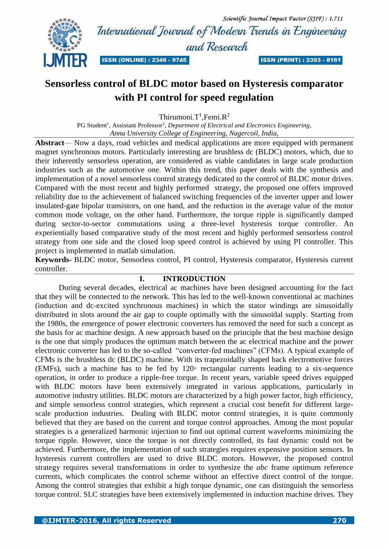
pass filter it will give the sinusoidal back emf. The hysteresis current controller will compare the
actual motor current and reference current waveform; the current controller will produce difference
as PWM pulses. This pulse is given to the voltage source inverter. The inverter will fed the voltage to
the motor so that stator current will decreased.
Fig 1. Block diagram of Sensorless BLDC motor
Sensor less control by using a hysteresis comparator method for consists of the LPFs for
suppressing the high switching frequency ripples, hysteresis comparators for generating three-phase
commutation signals, and a gating signals generator for generating six PWM signals. After sensing
the three-phase terminal voltages, each of the three-phase terminal voltages is fed into an LPF to
suppress the high switching frequency ripple or noise. As only two phases of the BLDC motor are
energized at any time, the back-EMF can be measured from its terminal voltage in the period of an
open phase (60°). During the two-phase conduction period (120°), the only difference between the
back-EMF and its terminal voltage is a stator impedance voltage drop, which may be considerably
small compared with the dc voltage source
. Fig 2. Circuit diagram of Sensorless BLDC motor
Therefore, the waveform of the terminal voltage is nearly the same as that of the back-EMF.
The terminal voltages can be used to detect the commutation points of the BLDC motor instead of
the back-EMFs at the proposed sensorless control. As the rotor speed increases, the percentage
International Journal of Modern Trends in Engineering and Research (IJMTER) Volume 03, Issue 01, [January– 2016] ISSN (Online):2349–9745 ; ISSN (Print):2393-8161
@IJMTER-2016, All rights Reserved 274
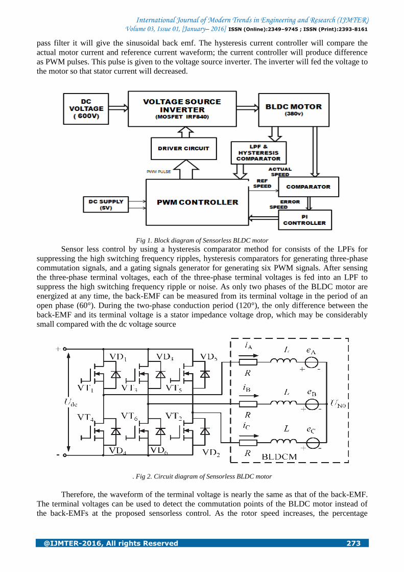
contribution of the phase lag to the overall period increases. The lag will disturb current alignment
with the back-EMF and will cause serious problems for commutation at high speed. The phase lag in
commutation can produce significant pulsating torques in such drive which may cause oscillations of
the rotor speed, and generate extra copper losses. In this paper, the cut-off frequency of the LPF is
determined on 2.5 kHz by considering both the phase lag and harmonic distribution of the back-
EMF. The hysteresis comparator is used to compensate for the phase lag of the back-EMFs due to
the LPF in order to determine the proper commutation sequence of the inverter according to the rotor
position. Also, it can prevent multiple output transitions by high frequency ripples in the terminal
voltages.
Fig 3. Hysteresis comparator
The outputs of the three-phase hysteresis comparators become three commutation signals (Za,
Zb, Zc), and then six gating signals can be generated through some logic equations. The filtered a-
phase terminal voltage is applied to the inverting input, and the filtered c-phase terminal voltage is
applied via R1 to the non-inverting input.
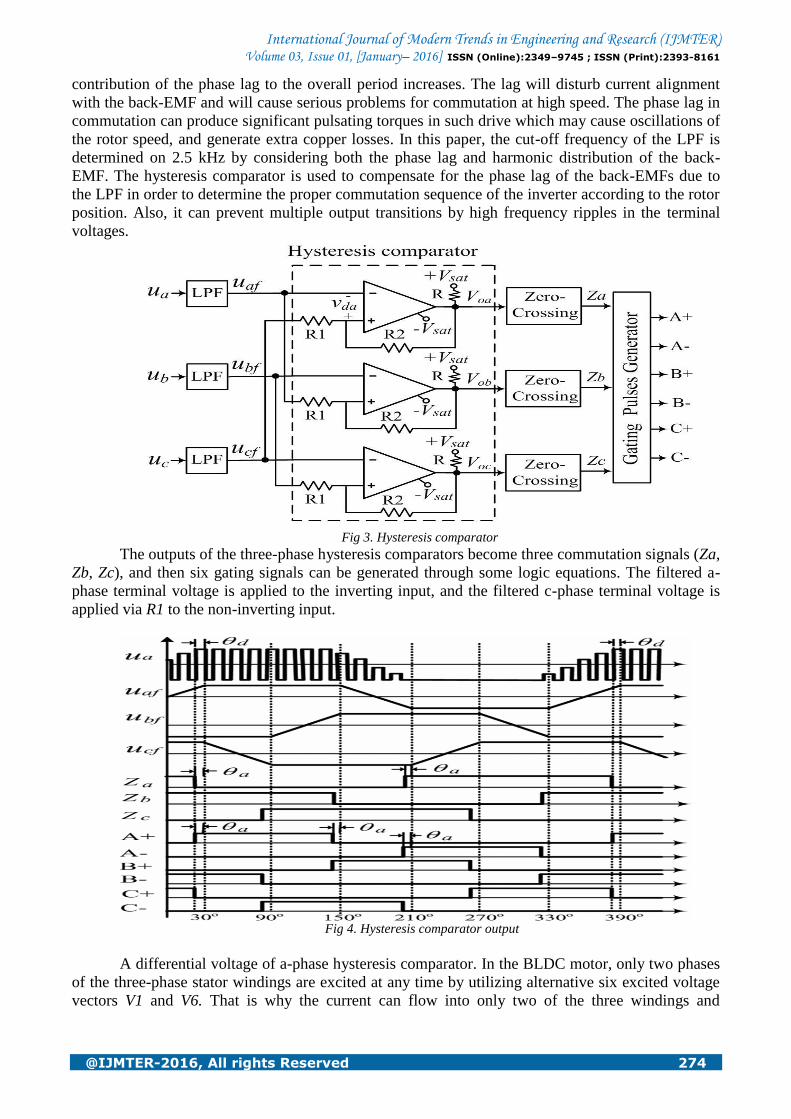
Fig 4. Hysteresis comparator output
A differential voltage of a-phase hysteresis comparator. In the BLDC motor, only two phases
of the three-phase stator windings are excited at any time by utilizing alternative six excited voltage
vectors V1 and V6. That is why the current can flow into only two of the three windings and

International Journal of Modern Trends in Engineering and Research (IJMTER) Volume 03, Issue 01, [January– 2016] ISSN (Online):2349–9745 ; ISSN (Print):2393-8161
@IJMTER-2016, All rights Reserved 275
commutated every 60° of electrical angle. At standstill, the initial rotor position is aligned into one of
six positions that are determined by the six excited voltage vectors to energize two phases of the
BLDC motor. As it is well known, the deviation of these voltage vectors is every 60° of electrical
angle.
Hysteresis-band PWM is basically an instantaneous feedback current control method of
PWM where the actual current continually tracks the command current within a hysteresis band.
Hysteresis control schemes are based on a nonlinear feedback loop with two level hysteresis
comparators. The switching signals are produced directly when the error exceeds an assigned
tolerance band. The following figure shows the operation principle of the hysteresis
modulation/control scheme.
Fig 5. Hysteresis current controller
The controller generates the sinusoidal reference current of desired magnitude and frequency
that is compared with the actual line current. If the current exceeds the upper limit of the hysteresis
band, the upper switch of the inverter arm is turned off and the lower switch is turned on. As a result,
the current starts to decay. If the current crosses the lower limit of the hysteresis band, the lower
switch of the inverter arm is turned off and the upper switch is turned on. As a result, the current gets
back into the hysteresis band. Hence, the actual current is forced to track the reference current within
the hysteresis band.
The speed can be controlled in a closed loop by measuring the actual speed of the motor. The
error in the set speed and actual speed is calculated. A Proportional plus Integral (P.I.) controller can
be used to amplify the speed error and dynamically adjust the PWM duty cycle. For low-cost, low-
resolution speed requirements, the Hall signals can be used to measure the speed feedback. A timer
from the Controller can be used to count between two Hall transitions. With this count, the actual
speed of the motor can be calculated. For high-resolution speed measurements, an optical encoder
can be fitted onto the motor, which gives two signals with 90 degrees phase difference.
Using these signals, both speed and direction of rotation can be determined. Also, most of the
encoders give a third index signal, which is one pulse per revolution. This can be used for
positioning applications. Optical encoders are available with different choices of Pulse Per
Revolution (PPR), ranging from hundreds to thousands. So finally the motor will run at constant
speed by using PI controller.

International Journal of Modern Trends in Engineering and Research (IJMTER) Volume 03, Issue 01, [January– 2016] ISSN (Online):2349–9745 ; ISSN (Print):2393-8161
@IJMTER-2016, All rights Reserved 276
III. SIMULATION RESULTS
To verify the feasibility of the proposed strategy, simulations are carried out.
Fig.6. Proposed system Simulink diagram
Fig.7. Three phase voltage source inverter output and back emf waveform of BLDC motor
Fig.8. Back emf waveform before and after filter

International Journal of Modern Trends in Engineering and Research (IJMTER) Volume 03, Issue 01, [January– 2016] ISSN (Online):2349–9745 ; ISSN (Print):2393-8161
@IJMTER-2016, All rights Reserved 277
Fig.9. Gate pulses to the inverter
Fig.10. Torque waveform of the BLDC motor
Fig.11. Speed waveform using PI controller
IV. CONCLUSIONS
This project presents a sensorless control based on a hysteresis comparator of terminal
voltage and a potential start-up method with a high starting torque for an automotive fuel pump
application. As the maximum commutation phase lag is significantly reduced from -13°to -3°by
adjusting both the resistance ratio and the output voltage level of the hysteresis comparator, The
commutation signal is nearly in phase with the back-EMF It can prevent multiple output transitions
at a hysteresis comparator by high frequency ripples in the terminal voltage. The hysteresis current
controller was reduced the stator current ripples. The closed loop speed control is achieved by using
PI controller.

International Journal of Modern Trends in Engineering and Research (IJMTER) Volume 03, Issue 01, [January– 2016] ISSN (Online):2349–9745 ; ISSN (Print):2393-8161
@IJMTER-2016, All rights Reserved 278
REFERENCES [1] Y.-C. Son, K.-Y. Jang, and B.-S. Suh, “Integrated MOSFET inverter module of low-power drive system,” IEEE
Trans. Ind. Appl., vol. 44, no. 3,pp. 878–886, May/Jun. 2008.
[2] A. Sathyan, N. Milivojevic, Y.-J. Lee, M. Krishnamurthy, and . Emadi,“An DSPIC30F4011-based novel digital
PWM control scheme for BLDC motor drives,” IEEE Trans. Ind. Electron., vol. 56, no. 8, pp. 3040–3049,Aug. 2009.
[3] G. J. Su and J. W. Makeover, “Low-cost sensor less control of brushless DC motors with improved speed range,”
IEEE Trans. Power Electron.,vol. 19, no. 2, pp. 296–302, Mar. 2004.
[4] C.-T. Pan and E. Fang, “A phase-locked-loop-assisted internal model adjustable-speed controller for BLDC motors,”
IEEE Trans. Ind. Electron., vol. 55, no. 9, pp. 3415–3425, Sep. 2008.
[5] C. Xia, Z. Li, and T. Shi, “A control strategy for four-switch three phase brushless dc motor using single current
sensor,” IEEE Trans. Ind. Electron., vol. 56, no. 6, pp. 2058–2066, Jun. 2009.
[6] F. Rodriguez and A. Emadi, “A novel digital control technique for brushless dc motor drives,” IEEE Trans. Ind.
Electron., vol. 54, no. 5, pp. 2365– 2373, Oct. 2007.
[7] T.-H. Kim, W.-T. Lee, C.-M. Lee, and J. Lee, “Finite-element analysis of brushless dc motor considering
freewheeling diodes and dc link voltage ripple,” IEEE Trans. Magn., vol. 39, no. 5, pp. 3274–3276,Sep. 2003.
[8] H.-W. Lee, T.-H. Kim, and M. Ehsani, “Practical control for improving power density and efficiency of the BLDC
generator,” IEEE Trans. PowerE ectron., vol. 20, no. 1, pp. 192–199, Jan. 2005.
[9] R. Carlson, L.-M. Milchel, and J. C. Fagundes, “Analysis of torque ripple due to phase commutation in brushless dc
machines,” IEEE Trans. Ind. Appl., vol. 28, no. 3, pp. 632–638, May/Jun. 1992.
[10] K.-J. Han, H.-S. Cho, D.-H. Cho, and H.-K. Jung, “Optimal core shape design for cogging torque reduction of
brushless dc motor using genetic algorithm,” IEEE Trans. Magn., vol. 36, no. 4, pp. 1927–1931,Jul. 2000.
[11] A. H. Niassar, A. Vahedi, and H. Moghbelli, “Analysis and control of commutation torque ripple in four-switch
three-phase brushless dc motor drive,” in Proc. IEEE Ind. Technol. Conf., 2006, pp. 239–246.
1T.Thirumoni received the B.E. Degree in Electrical and Electronics Engineering from
Anna university College of Engineering, Nagercoil, Anna University, Chennai, India in 2011
and doing final year Post graduation in Power Electronics & Drives in Anna University
College of Engineering, Nagercoil. Anna University, Chennai, India 2016.
2R.Femi received the B.E. Degree in Electrical and Electronics Engineering from CSI
Institute of Technology, Nagercoil, Anna University, Chennai, India in 2009 and Post-
graduation in Applied Electronics Engineering in PSNA College of Engineering &
Technology, Dindugal. Anna University, Chennai, India 2011. Now She is working as a
Assistant Professor in Anna University College of Engineering, Nagercoil.