Embed Size (px)
Citation preview

IJSRD - International Journal for Scientific Research & Development| Vol. 2, Issue 09, 2014 | ISSN (online): 2321-0613
All rights reserved by www.ijsrd.com 798
Sensor Less Control of Z-Source Inverter Fed BLDC Motor Using Sliding
Mode Observer K.Kalpanadevi
1, M.Ramesh kanna
2, Mrs.S.Sivaranjani
3
1,2PG scholar,
3Assistant Professor
1,2M.E. Power Systems Engineering,
3Department of EEE
1,2,3V.S.B.Engineering College, Karur-639111
Abstract— Z – source inverters have been recently proposed
as an alternative power conversion concept as they have
both voltage buck and Boost capabilities. These inverters
use a unique impedance network, coupled between the
power source and converter circuit, to provide both voltage
buck and boost properties, which cannot be achieved with
conventional voltage source and current source inverters. This paper deals with sensor less control of Z-source
inverter under Direct torque control to get an instantaneous
torque control. Sliding mode observer is a parameter for
estimating the phase to phase trapezoidal back-EMF in
sensor less mode. Z-source inverter is used to boost up the
voltage. The simulation results of Z-source inverter is
shown.
Key words: BLDC motor, Z-source inverter(ZSI),Sliding
mode observer, Direct Torque Control
I. INTRODUCTION
BLDC motors are becoming so popular in industrial
applications. Because of its High efficiency, High torque,
Low acoustic noise, Less maintenance, longer life time and
large inertia ratio when compared to brushless AC motors.
BLDC motor is also known as electronically commutated
motors are synchronous motors. A BLDC motor is an inside
out DC commutator motor with mechanical commutator
replaced by an electronic switching converters. The existing
two converters are voltage source inverter and current
source inverters. In voltage source inverter and current
source inverter the reliability is low, complexity is high and
the power factor is low with decreasing speed. To overcome
these limitations z-source inverter is used
II. Z- SOURCE INVERTER
Z-Source inverter is a type of power inverter that converts
direct current into alternating current. It works as Buck-
boost inverter. Z-source inverter eliminates the problems of
voltage source inverter and current source inverter. Z-source
inverter is a two-port network that consists of inductance
and capacitance which are connected in x-shape to provide
an impedance source.. With the unique LC network, we can
intentionally add the shoot through state to boost the output
voltage.. Z-source inverters has some advantages when
compared to voltage source inverters and current source
inverters. By using z-source inverter the switching losses
can be reduced. The z-source inverter is applied to all DC-AC,
AC-DC, AC-C and DC-DC power conversion.
Fig. 1: Z-Source Inverter
A. Operation of z-source inverter
The figure 1 shows the Z-source inverter. It consists of
inductor, capacitor and diode which are connected in series
with the supply. The function of diode is to block the
reverse current. Z-source inverter has the capability of
allowing the power switches of a phase leg to be turned on
when compared to voltage source inverter.
Fig. 2: Non Shoot Through Mode Of Zsi
Z-source inverter can produced the high output
voltage even for lower input voltage. The z-source inverter
has two operating modes. Due to some additional special
structure, the ZSI has an additional switching state, when the
load terminals are shorted through upper and lower
switching devices of any one phase leg, which is known as
shoot through. The input diode is reverse biased during the
shoot through mode. There are shoot-through mode and
non-shoot through mode. The block diagram of non-shoot
through mode is shown in figure 2. The figure 3 shows
shoot through mode of Z-source inverter
Fig. 3: Shoot Through Mode Of Zsi
Sensor Less Control of Z-Source Inverter Fed BLDC Motor Using Sliding Mode Observer
(IJSRD/Vol. 2/Issue 09/2014/186)
All rights reserved by www.ijsrd.com 799
At that time the input dc source is isolated from the
load and two capacitors are discharges the energy to the
inductors and to the load. This mode is not allowed to
inverter control strategies. In order to reduce the volume and
cost of passive elements of Z-source inverter, it is important
to keep the shoot through duty ratio constant.
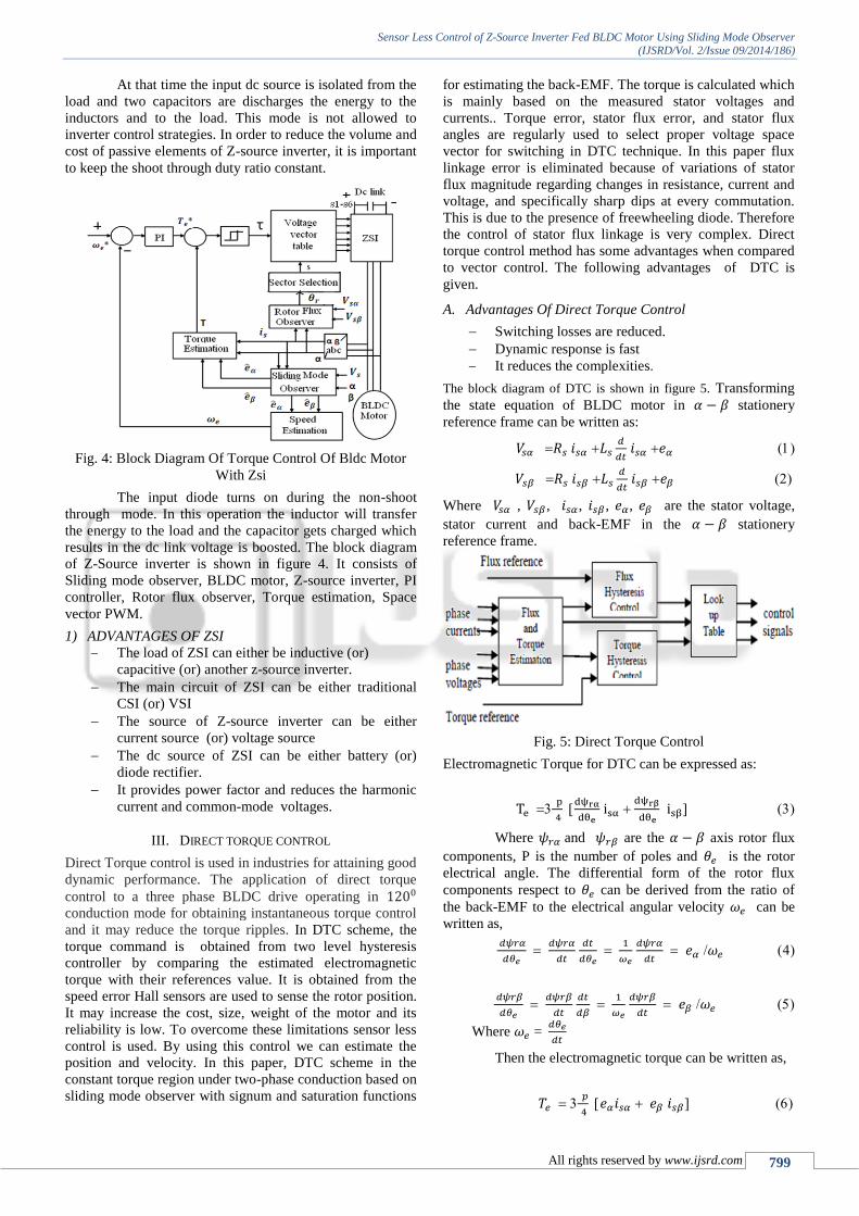
Fig. 4: Block Diagram Of Torque Control Of Bldc Motor
With Zsi
The input diode turns on during the non-shoot
through mode. In this operation the inductor will transfer
the energy to the load and the capacitor gets charged which
results in the dc link voltage is boosted. The block diagram
of Z-Source inverter is shown in figure 4. It consists of
Sliding mode observer, BLDC motor, Z-source inverter, PI
controller, Rotor flux observer, Torque estimation, Space
vector PWM.
1) ADVANTAGES OF ZSI
The load of ZSI can either be inductive (or)
capacitive (or) another z-source inverter.
The main circuit of ZSI can be either traditional
CSI (or) VSI
The source of Z-source inverter can be either
current source (or) voltage source
The dc source of ZSI can be either battery (or)
diode rectifier.
It provides power factor and reduces the harmonic
current and common-mode voltages.
III. DIRECT TORQUE CONTROL
Direct Torque control is used in industries for attaining good
dynamic performance. The application of direct torque
control to a three phase BLDC drive operating in
conduction mode for obtaining instantaneous torque control
and it may reduce the torque ripples. In DTC scheme, the
torque command is obtained from two level hysteresis
controller by comparing the estimated electromagnetic
torque with their references value. It is obtained from the
speed error Hall sensors are used to sense the rotor position.
It may increase the cost, size, weight of the motor and its
reliability is low. To overcome these limitations sensor less
control is used. By using this control we can estimate the
position and velocity. In this paper, DTC scheme in the
constant torque region under two-phase conduction based on
sliding mode observer with signum and saturation functions
for estimating the back-EMF. The torque is calculated which
is mainly based on the measured stator voltages and
currents.. Torque error, stator flux error, and stator flux
angles are regularly used to select proper voltage space
vector for switching in DTC technique. In this paper flux
linkage error is eliminated because of variations of stator
flux magnitude regarding changes in resistance, current and
voltage, and specifically sharp dips at every commutation.
This is due to the presence of freewheeling diode. Therefore
the control of stator flux linkage is very complex. Direct
torque control method has some advantages when compared
to vector control. The following advantages of DTC is
given.
A. Advantages Of Direct Torque Control
Switching losses are reduced.
Dynamic response is fast
It reduces the complexities.
The block diagram of DTC is shown in figure 5. Transforming
the state equation of BLDC motor in stationery
reference frame can be written as:
Where , , , , , are the stator voltage,
stator current and back-EMF in the stationery
reference frame.
Fig. 5: Direct Torque Control
Electromagnetic Torque for DTC can be expressed as:
Where and are the axis rotor flux
components, P is the number of poles and is the rotor
electrical angle. The differential form of the rotor flux
components respect to can be derived from the ratio of
the back-EMF to the electrical angular velocity can be
written as,
Where =
Then the electromagnetic torque can be written as,

Sensor Less Control of Z-Source Inverter Fed BLDC Motor Using Sliding Mode Observer
(IJSRD/Vol. 2/Issue 09/2014/186)
All rights reserved by www.ijsrd.com 800
Rotor angle velocity calculation can be obtained from the
estimation of sliding mode observer.
B. ROTOR FLUX OBSERVER
The rotor flux components can be calculated by using rotor
flux observer
∫(
)
∫(
)
omagnetic torque in DTC scheme, the
rotor flux vector position can be obtained as,
(
)
IV. SLIDING MODE OBSERVER
Sliding mode observer is used to estimate the stator flux. It
is a non-linear control method that may modifies the system
performance. The SMO can be designed with two
approaches. In the first approach the system equations can
be converted into two suitable sub systems. The second
approach is for designing the state observer. SMO is also
used to estimate the back-EMFs accurately. The equations
of SMO is stated as,
Where, , , , are the estimation of
axes stator currents and back-EMFs respectively. In
the conventional method, a single observer gain value is
selected for estimating back EMF which suits well only for
particular range of speeds for which the observer gain is
deigned. The invariable observer gain produces multiple
zero crossing for low speeds and a phase delay for large
range of speeds. In the proposed method, value of the
observer gain varies in accordance with the variation of
speed to match the estimated back EMF with actual. When
SMO with signum functions is implemented to estimate the
back-EMF of BLDC motor. So chattering occurs when
using signum function. In order to reduce the chattering ,
instead of signum functions saturation is given.
A. Rotor Position And Speed Estimation
The rotor position can be determined from the
estimation of back-EMFs. The rotor position can be
calculated by using the following equation.
= (
) (12)
The rotor angular velocity can be estimated by the
following formula
( )
Where, ( ) is the amplitude of phase to
phase back-EMFs and is the back-EMF s constant.
V. SIMULATION AND RESULTS
The proposed sensor less control of Z-source inverter fed
BLDC motor using sliding mode observer has been verified
through the simulation diagram. The reference speed is set
by 1500 rpm. The supply voltage is set by 250v. By
controlling the current speed can be controlled. The theta
value is estimated by integrating the speed. The flux value
can be obtained through the stator voltage and current. The
reference speed is compared with the calculated speed.
Similarly, the reference torque is compared with the
measured torque. Figure (6) shows the simulation diagram.
Fig. 6: Simulation Diagram
The simulation diagram of Z-Source Inverter is shown in the
following figure. The Z-Source Inverter is to boost the
voltage.
Fig. 7: Simulation Diagram For Z-Source Inverter
Fig. 8: Three Phase To Two Phase Stator Current
Conversion

Sensor Less Control of Z-Source Inverter Fed BLDC Motor Using Sliding Mode Observer
(IJSRD/Vol. 2/Issue 09/2014/186)
All rights reserved by www.ijsrd.com 801
Fig. 9: Simulation Of Space Vector Pulse Width Modulation
Fig. 10: Stator Voltage
Fig. 11: Stator Current
Fig. 12: Rotor Speed
Fig. 13: Trapezoidal Back-Emf
Fig. 14: Torque Waveform
VI. CONCLUSION
This paper describes about the Sensor less control of Z-
Source Inverter fed BLDC motor with Sliding Mode
Observer. The torque ripples and losses can be minimized
when using the Direct Torque control scheme. The
Trapezoidal back-EMF waveform is estimated by using
SMO technique. Space vector pulse width modulation is
used as a modulation technique. The efficiency has been
increased by reducing the total harmonic distortion. Voltage
has been increased while implementing the Z-source
inverter. The speed can be controlled by controlling the
current. By integrating the speed the value of theta has to be
estimated. The estimated speed is compared with the
reference speed. Similarly, the calculated torque is
compared with the reference torque. The flux value can be
estimated from the stator voltage and current. Sliding mode
observer is implemented to reduce the overall system error
and estimates the back-EMF.
From the simulated results it is evident that the
torque ripples are reduced. The main advantage of this
method is it uses sensor less technique for the three phases.
So it reduces the cost, size and weight.
REFERENCES
[1] Hyun Lee and Jangmyung Lee, “Design of iterative
sliding mode observer for sensorless PMSM
control,” IEEE Trans. on Control Syst. Technol.,
vol. 21,no. 4, pp. 1394-1399, Jul. 2013.
[2] Salih Baris Ozturk and Hamid A. Toliyat, “Direct
torque control of brushless dc motor with non-
sinusoidal back-EMF,”IEEE Int. Electric machines
and Drives Conf., vol. 1, pp. 165-171, 2007.
[3] Salih Baris Ozturk and Hamid A. Toliyat, “Direct
torque and indirect flux control of brushless dc
motor,” IEEE/ASME Trans. on Mechatronics, vol.
16, no. 2, Apr. 2011
[4] A. Deenadayalan and G. Saravana Ilango,
“Modified sliding mode observer for position and
speed estimations in brushless dc motor,” IEEE
Annu. India Conf. (INDICON), pp. 1-4, 2011.
[5] Chen Wei, Chen Yankun, Li Hongfeng and Song
Zhanfeng, “Sensorless control of permanent
magnet synchronous motor based on sliding mode
observer,”IEEE 7th Int. Power Electron. and
Motion Control Conf., Jun. 2012.
[6] Vidya Sojan, and Mrs. Lekshmi A “Performance
Analysis of Z-Source Inverter fed PM BLDC
Motor Drive” R.

Sensor Less Control of Z-Source Inverter Fed BLDC Motor Using Sliding Mode Observer
(IJSRD/Vol. 2/Issue 09/2014/186)
All rights reserved by www.ijsrd.com 802
[7] Krishnan, Electric Motor Drives-Modeling
Analysis
and Control” Prentice Hall,2005.
[8] Poh Chiang Loh, D. M. Vilathgamuwa, Y. S. Lai,
G. T. Chua and Y.W.Li, “PWM of Z-Source
Inverter”,
IEEE Transactions on Power
Electronics,Volume20, pp. 1346-1355,
November2005.
[9] Miaosen shen, Jin Wang, Alan Joseph, FangZ.
Peng, Leon M. Tolbert, and Donald J. Adams,
“Comparison
of Traditional Inverter and Z-Source Inverter for
Fule Cell Vehicles,” in Proceedings IEEE WPET
2004, pages 125-132.