Embed Size (px)
Citation preview

University of Pennsylvania University of Pennsylvania
ScholarlyCommons ScholarlyCommons
Departmental Papers (ESE) Department of Electrical & Systems Engineering
October 2006
Sensor Data Fusion for Body State Estimation in a Hexapod Robot Sensor Data Fusion for Body State Estimation in a Hexapod Robot
With Dynamical Gaits With Dynamical Gaits
Pei-Chun Lin University of Pennsylvania
Haldun Komsuoglu University of Pennsylvania
Daniel E. Koditschek University of Pennsylvania, [email protected]
Follow this and additional works at: https://repository.upenn.edu/ese_papers
Recommended Citation Recommended Citation Pei-Chun Lin, Haldun Komsuoglu, and Daniel E. Koditschek, "Sensor Data Fusion for Body State Estimation in a Hexapod Robot With Dynamical Gaits", . October 2006.
Copyright IEEE 2006. Reprinted from IEEE Transactions on Robotics, Volume 22, Issue 5, October 2006, pages 932-943.
This material is posted here with permission of the IEEE. Such permission of the IEEE does not in any way imply IEEE endorsement of any of the University of Pennsylvania's products or services. Internal or personal use of this material is permitted. However, permission to reprint/republish this material for advertising or promotional purposes or for creating new collective works for resale or redistribution must be obtained from the IEEE by writing to [email protected]. By choosing to view this document, you agree to all provisions of the copyright laws protecting it.
This paper is posted at ScholarlyCommons. https://repository.upenn.edu/ese_papers/202 For more information, please contact [email protected].

Sensor Data Fusion for Body State Estimation in a Hexapod Robot With Sensor Data Fusion for Body State Estimation in a Hexapod Robot With Dynamical Gaits Dynamical Gaits
Abstract Abstract We report on a hybrid 12-dimensional full body state estimator for a hexapod robot executing a jogging gait in steady state on level terrain with regularly alternating ground contact and aerial phases of motion. We use a repeating sequence of continuous time dynamical models that are switched in and out of an extended Kalman filter to fuse measurements from a novel leg pose sensor and inertial sensors. Our inertial measurement unit supplements the traditionally paired three-axis rate gyro and three-axis accelerometer with a set of three additional three-axis accelerometer suites, thereby providing additional angular acceleration measurement, avoiding the need for localization of the accelerometer at the center of mass on the robot’s body, and simplifying installation and calibration. We implement this estimation procedure offline, using data extracted from numerous repeated runs of the hexapod robot RHex (bearing the appropriate sensor suite) and evaluate its performance with reference to a visual ground-truth measurement system, comparing as well the relative performance of different fusion approaches implemented via different model sequences.
Keywords Keywords extended kalman filter (ekf), hybrid estimation model, inertial measurement unit (imu), legged robot, leg pose sensor (lps), sensor fusion
Comments Comments Copyright IEEE 2006. Reprinted from IEEE Transactions on Robotics, Volume 22, Issue 5, October 2006, pages 932-943.
This material is posted here with permission of the IEEE. Such permission of the IEEE does not in any way imply IEEE endorsement of any of the University of Pennsylvania's products or services. Internal or personal use of this material is permitted. However, permission to reprint/republish this material for advertising or promotional purposes or for creating new collective works for resale or redistribution must be obtained from the IEEE by writing to [email protected]. By choosing to view this document, you agree to all provisions of the copyright laws protecting it.
This journal article is available at ScholarlyCommons: https://repository.upenn.edu/ese_papers/202

932 IEEE TRANSACTIONS ON ROBOTICS, VOL. 22, NO. 5, OCTOBER 2006
Sensor Data Fusion for Body State Estimation in aHexapod Robot With Dynamical Gaits
Pei-Chun Lin, Member, IEEE, Haldun Komsuoglu, Member, IEEE, and Daniel E. Koditschek, Fellow, IEEE
Abstract—We report on a hybrid 12-dimensional full body stateestimator for a hexapod robot executing a jogging gait in steadystate on level terrain with regularly alternating ground contact andaerial phases of motion. We use a repeating sequence of contin-uous time dynamical models that are switched in and out of an ex-tended Kalman filter to fuse measurements from a novel leg posesensor and inertial sensors. Our inertial measurement unit supple-ments the traditionally paired three-axis rate gyro and three-axisaccelerometer with a set of three additional three-axis accelerom-eter suites, thereby providing additional angular acceleration mea-surement, avoiding the need for localization of the accelerometer atthe center of mass on the robot’s body, and simplifying installationand calibration. We implement this estimation procedure offline,using data extracted from numerous repeated runs of the hexapodrobot RHex (bearing the appropriate sensor suite) and evaluate itsperformance with reference to a visual ground-truth measurementsystem, comparing as well the relative performance of different fu-sion approaches implemented via different model sequences.
Index Terms—Extended Kalman filter (EKF), hybrid estimationmodel, inertial measurement unit (IMU), legged robot, leg posesensor (LPS), sensor fusion.
I. INTRODUCTION
THE hexapod RHex [1] exhibits unprecedented mobility fora legged autonomous robot [2]. Using an open loop feed-
forward control strategy, the machine runs at speeds exceedingfive body lengths per second on even terrain [3], and negoti-ates badly broken and unstable surfaces, as well as stairs [4],[5]. Initial empirical studies of controllers relying on cheap andinaccurate sensory feedback cues have resulted in significantlyimproved performance (inclinometers on slopes [6]; leg touch-down cues over broken terrain [7]) and entirely new behaviors(body-pitch-sensitive accelerometers for flips [8] and bipedalgaits [9]; leg touchdown cues for pronking gaits [10]). Theo-retical considerations and simulation evidence [11] suggest thatthe availability of accurate, full body state estimates, as well asforce interactions with the surrounding environment throughoutthe stance and aerial phases of locomotion, should confer con-siderably greater agility still.
However, building a sensor suite that can deliver full bodystate information—six configuration coordinates together with
Manuscript received June 21, 2005; revised February 21, 2006. This paperwas recommended by Associate Editor G. Sukhatme and Editor H. Araiupon evaluation of the reviewers’ comments. This work was supported byDARPA/SPAWAR under Contract N66001-00-C-8026 and under ContractN66001-03-C-8045. This paper was presented in part at the IEEE InternationalConference on Robotics and Automation, Barcelona, Spain, April 2005.
The authors are with the Department of Electrical and Systems Engi-neering, University of Pennsylvania, Philadelphia, PA 19104 USA (e-mail:[email protected]; [email protected]; [email protected]).
Digital Object Identifier 10.1109/TRO.2006.878954
Fig. 1. RHex with 4-bar compliant legs equipped with strain-based leg config-uration sensors (LPS) stands on the meadow.
their six time derivatives—at data rates relevant to motor con-trol ( 1 kHz) remains a challenging problem in legged roboticsbecause of the limitation of onboard instrumentation combinedwith extreme variations in operating regime. The traditional in-ertial measurement unit (IMU) for rigid bodies in flight typicallylies out of the range of robotics applications because of its costand excessive volume. Appropriately low-cost and small IMUpackages typically suffer severe drift and saturation/sensitivityproblems. Moreover, while ballistic flight models are quite ac-curate, legged machines by definition spend a large fraction oftheir locomotion duty cycle in ground contact. Therefore, thedetermination of an appropriate model is greatly complicated bythe uncertainty in ground conditions (local terrain shape, slip-periness, and damping and compliance properties) and leg con-tact conditions (which legs are in stance).
Recently, we introduced a novel leg-strain-based full bodypose estimator [hereafter referred to as the leg pose sensor(LPS)] for a hexapod robot in tripod stance1 [12] with practicalimplementation on RHex, pictured in Fig. 1. In that paper,we demonstrated that a memoryless transformation built from(data-driven phenomenological) models relating leg strain toconfiguration, coupled with a conventional kinematic modelof leg configuration to body pose, can accurately estimatebody position and orientation when the robot’s three non-collinear legs are fixed on the ground (i.e., in each tripodstance). In walking gaits with no aerial phase, a complete6-degree-of-freedom (DOF) body pose in continuous time caneasily be extended from the above tripod-stance body pose,in principle, from a purely kinematic model without velocitystate estimation [12]. In contrast, an alternating tripod runner
1This term denotes the mode of leg contact wherein the three toes of the frontand rear ipsilateral legs and the middle contralateral leg of a tripod are all incontact with the ground.
1552-3098/$20.00 © 2006 IEEE

LIN et al.: SENSOR DATA FUSION FOR BODY STATE ESTIMATION 933
experiencing significant aerial phases (with the concomitanttouchdown/liftoff transients)2 would seem to require full bodystate estimation, both velocity and configuration information.In order to build the required estimators, of course, the sensorsuite must incorporate enough information to allow the recon-struction of full state from the record of past measurement filledin by some dynamical model.
During stance, complete 12-DOF continuous-time body stateestimates can be computed from the LPS by means of directmeasurement and recourse to online differentiation. Absentany other available sensors, these stance state estimates maybe carried through the transient and flight phases only by theadoption of some dynamical prediction model. Although theLPS delivers accurate high-bandwidth body pose estimatesduring stance (potentially marred by drift effects resulting fromtoe slippage [12]), overall performance throughout a completestride is limited by inaccuracies in the transient phase modelsand the deleterious effects of online differentiation [14]. Incontrast, an IMU continuously delivers derivative (typicallytranslational/linear acceleration and rotational/angular velocity)information over all phases of a stride. Saturation and drifteffects in the physical sensor, however, can dramatically reducethe accuracy of the resulting integrated position estimates. Thecomplementary strengths and weaknesses of the LPS and IMUpromise a better body state estimate than either, alone, couldachieve. In this paper, we demonstrate that that promise can beachieved.
The traditional IMU (TIMU), comprised of three accelerom-eters (for linear acceleration) and three gyros (for angularvelocity), can readily provide full 12-DOF body state esti-mates when it is precisely located, carefully calibrated, andits output filtered appropriately. Unlike the translational statecomponents, whose estimates require double integration ofthe accelerometer data, the rotational component estimates,requiring only a single integration step, might be imagined toincur smaller errors. However, these available sensory sourcesdo not well subserve estimation models that take second-orderdynamics into account. In the absence of angular accelerationmeasurements, the literature reveals a strong predilection forfirst-order dynamics [15] (usually assuming constant velocity),in preference to the direct differentiation that would be other-wise required without very accurate (and formally observable)dynamical models. Moreover, the general attitude toward con-temporary low-cost microelectromechanical system (MEMS)gyros suggests that their inferior drift and saturation propertiesrelative to MEMS accelerometers may vitiate any advantage atthe signal processing stage. The considerable effort requiredto calibrate gyros3 detracts further from their inclusion in anIMU. These facts all suggest the utility of angular acceleration
2Note that hexapedal running gaits need not entail an aerial phase to be “dy-namical” in the sense of requiring careful management of kinetic energy to in-sure balance and steady progress [13]. However, RHex develops its greatest en-ergy efficiency and highest speeds in gaits with long aerial phases; hence, inthis paper, we focus our empirical tests on a “jogging” gait with an aerial phaseexceeding 25% of the complete stride. By “touchdown” and “liftoff” transients,we refer to intermediate configurations where some number of legs fewer thanthree are in ground contact.
3Acquiring for these low-cost MEMS devices the necessary gyro calibrationdata (the map from raw sensor output to angular rate with temperature com-pensation) generally provided by high-end commercial gyros requires a vari-able-speed-controlled turntable with temperature adjustment capability.
data and angular velocity data, if possible, from MEMS ac-celerometers for fusion. These considerations motivated King’s[16] introduction of a novel nine-axis accelerometer suite,designed to measure angular acceleration and possibly angularvelocity with no need for accompanying gyros. Unfortunately,this scheme requires that the accelerometer suite be very accu-rately installed in a specific spatial configuration. The fallingcost and volume of MEMS-based accelerometers, togetherwith the possibility of eliminating entirely such (theoreticallyinnocent, but pragmatically onerous) installation requirements[16] motivates our introduction of a new 12-axis accelerom-eter suite—an advanced IMU (AIMU) capable of deliveringlinear/angular acceleration and angular velocity. We will showin Section III-B and Appendix I that the 12-axis accelerometersuite is theoretically capable of estimating all three aspectsof body state with no recourse to gyros, but is impractical inour setting as a result of numerical ill-conditioning dependentupon the small baseline RHex’s body affords. Therefore, alongwith the traditional 3-axis rate gyro, this 12-axis accelerometercomprises the AIMU that we join in this paper to our previousLPS.
Developing an effective approach to modeling a legged robotwhose running gait is to be stabilized by state feedback esti-mates raises the prospect of entering upon a circular path withno clear starting point. For an -legged machine, there arepossible formal Lagrangian models: touchdown-stick, touch-down-slip, and liftoff on each leg. These models include kine-matic and dynamic properties of the legs whose small relativemass lends them at best negligible influence upon the body,apart from the actuators’ effects. Hence, the adoption of an ap-propriately abstracted (12-dimensional or lower) family of ap-proximate models has strong appeal. Moreover, the approach togait stabilization that we favor provides growing theoretical [11]and empirical [8] justification for the validity of these lower-di-mensional “template” control models. These abstracted modelsapply to the steady-state conditions that emerge from well-regu-lated gaits. On the one hand, tractable feedback controllers thatrestore these gaits rely upon accurate estimates; on the otherhand, tractable filters based upon familiar dynamical models canbe expected to yield accurate estimates only within well-con-trolled gaits. For the purposes of intelligent sensor develop-ment, we rely upon open-loop stabilizing gaits developed byoffline tuning experiments [3] to bring the robot to a reliablesteady-state condition, wherein familiar, tractable models canbe readily implemented. Having established and verified the ef-ficacy of these procedures for extracting reliable state estimatesfrom the available sensor suite, future research will address theneed for and possibility of introducing more accurate physicalmodels, as well as switching them in and out as the leg contactconditions change during transients.
The idea of sensor fusion has spread widely within themobile robotics community, largely for application to wheeledvehicles, addressing algorithm development [17], controllerdesign [18], and some practical implementation. This literatureincludes navigation systems equipped with IMU alone usingKalman filtering [15], IMU/GPS fusion, sensor fault detection[19], model selection [20], and IMU/vision fusion [21]. How-ever, for legged robots, we have found only a very few accountsof sensor fusion, addressing such problems as sonar-basedlocalization [22] and multilayered-decision algorithms [23].
934 IEEE TRANSACTIONS ON ROBOTICS, VOL. 22, NO. 5, OCTOBER 2006
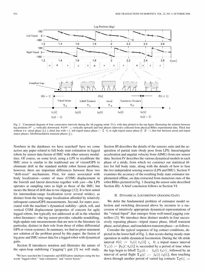
Fig. 2. Conceptual diagram of four consecutive intervals during the ith jogging stride S(i), with data plotted in the top figure illustrating the relation betweenleg positions (0 = vertically downward; �180 = vertically upward) and four phases (intervals) collected from physical RHex experimental data. Thick linewithout / .: aerial phase (jAj); thick line with / .: left tripod stance phase (` L a) or right tripod stance phase (` R a); thin line between aerial and tripodstance phases: liftoff/touchdown transient phases (k).
Nowhere in the databases we have searched4 have we comeacross any paper related to full body state estimation in leggedrobots by sensor data fusion of IMU with other sensory modal-ities. Of course, on some level, using a LPS to recalibrate theIMU error is similar to the traditional use of vision/GPS toeliminate drift in the standard mobile robot fusion problem;however, there are important differences between these two“drift-reset” mechanisms. First, for states associated withbody localization—center of mass (COM) displacement inthe fore/aft and lateral directions together with yaw—the LPSoperates at sampling rates as high as those of the IMU, butincurs the threat of drift due to toe slippage [12]. It is best suitedfor intermediate-range localization (over several strides), asdistinct from the long-range localization afforded by relativelyinfrequent camera/GPS measurements. Second, for states asso-ciated with the machine’s dynamical stability—pitch, roll, andvertical COM displacement (properties of concern for agilelegged robots, but typically not addressed at all in the wheeledrobot literature)—the leg sensor provides valuable nondrifting,high-update-rate measurements that are new to the literature (inparticular, distinct in their role from those of either differentialGPS or vision systems). In summary, we find no prior statementnor solution of the problem posed by this paper: the fusion ofleg pose and IMU sensor data for a legged robot with dynamicalgaits.
Section II introduces notation and illustrates the nature ofthe open-loop stabilizing (“jogging”) gait [3] we will study.
4We have searched the Compendex and IEEExplore databases using the keywords “legged robot,” “state estimation,” and “sensor fusion.”
Section III describes the details of the sensory suite and the ac-quisition of partial state (body pose from LPS; linear/angularacceleration and angular velocity from AIMU) from raw sensordata. Section IV describes the various dynamical models in eachphase of a stride, from which we construct our statistical fil-ters for full body state, along with the details of how to fusethe two independent sensing sources (LPS and IMU). Section Vexamines the accuracy of the resulting body state estimator im-plemented offline, on data extracted from numerous runs of therobot RHex pictured in Fig. 1 (bearing the sensor suite describedSection III). A brief conclusion follows in Section VI.
II. DYNAMICAL LOCOMOTION (JOGGING GAIT)
We defer the fundamental problem of estimator model se-lection and switching discussed above by recourse to a suc-cession of intuitively appropriate dynamical representations ofthe “virtual biped” that emerges from well-tuned jogging con-trollers [3]. We introduce three distinct models in four succes-sively repeating phases—tripod stance phase, liftoff transientphase, aerial phase, and touchdown transient phase—as follows.
Consider the typical sequence of leg contact conditions, de-picted in the lower half of Fig. 2, that occurs during steady-stateoperation in stable dynamical locomotion. During the th strideinterval , a tripod stance interval
is succeeded by a period of time whenthe legs begin to liftoff , followed by aninterval of aerial flight , then touchingdown through another period of varied leg contacts

LIN et al.: SENSOR DATA FUSION FOR BODY STATE ESTIMATION 935
to the fixed tripod stance interval of thenext stride . We consider the liftoff and touchdownintervals and “transients” because they typicallyexhibit complex sequences of successive leg contacts that re-veal little consistent pattern from run to run (or, often, evenfrom stride to stride). In practical implementation, the crucialleg contact information required to detect the onset and termi-nation of each of these phases of a stride may be gleaned di-rectly from the individual leg-strain-based touchdown/configu-ration sensors [12]. The top half of Fig. 2 shows the relationbetween these four phases and leg positions of two tripods gen-erated by the custom Buehler Clock [2].
III. PARTIAL-STATE MEASUREMENTS OUTPUT
DIRECTLY FROM SENSOR
A. Body Pose From LPS
A full 6-DOF body pose (COM displacement in lateral ,fore/aft , vertical directions, and body orientation inpitch , roll , and yaw ) for a hexapod robot in eachtripod stance can be obtained from a recently developed novelleg-strain-based configuration measurement system [12]. Thisbody pose estimate is computed using a conventional (memory-less) kinematic model generally expressed in the form
(1)
where or denotes left/right tripod,denotes the sensory measurements available regarding the con-figuration of the kinematic chain connecting the robot body tothe th toe, and denotes the vector from COM to hip ofthe th leg. In the case of RHex, with one actuated rotationalDOF associated with each compliant leg, can be denoted
, where denotes the thleg position from encoder measurement, , and denotes amemoryless transformation from (data-driven phenomenolog-ical) models relating leg strain to the th leg configuration,detailed in [12].
B. Linear/Angular Acceleration and Angular Velocity FromAIMU With 12-Axis Accelerometer Suite and 3-Axis Gyro
The TIMU consisting of a 3-axis accelerometer installed atthe COM and a 3-axis gyro on the body delivers COM linear ac-celeration ( ) and body angular velocity ( ) in sixindependent dimensions. In order to obtain angular accelerationdata ( ) as an input to a complete second-order dynamicalmodel for the rotational state, we propose a general method thatalgebraically computes six independent (translational and rota-tional) acceleration measurements, as well as three independentangular velocity measurements from a 12-axis accelerometersuite using the kinematic relationships of rigid body motion, asfollows.
The acceleration vector in an inertial “world” frame of apoint , rigidly attached to an accelerating “body” frame with
origin , is a function of the body’s angular velocity and an-gular acceleration , as well as the translational acceleration ofthe origin given by
(2)
where , the fixed position vector of relative to the body, ispresumed known a priori. In general, we are interested in themotion of the body relative to the world; hence, we seek to ex-tract from measurements of the left-hand quantities informationsufficient to derive the right-side unknowns: the COM transla-tional acceleration (usually equal to the origin of bodyframe)
and the angular acceleration and velocity
Note that the latter three variables appear in a quadratic form;hence, (2) defines a function that is linear in the six unknowns,
, , and linear in
the six distinct second-degree monomials of formed fromthe three unknowns of . In Appendix I-A, we show how to in-vert the quadratic map from to , thereby establishingthat the determination of the nine unknowns in (2) reduces to alinear computation that we will proceed to detail, at the expenseof requiring three additional measurements beyond the nine in-trinsic dimensions of the data.
The proposed accelerometer suite depicted in Fig. 3 yields a12-dimensional vector of measurements
comprised of four distinct spatial acceleration vectors(following upon a very simple calibration procedurefrom raw accelerometer outputs detailed in Appendix II)
, obtained at the four locationsspecified by the position vectors
In each case, , the measured acceleration vectoris linearly related to the 12 unknowns

936 IEEE TRANSACTIONS ON ROBOTICS, VOL. 22, NO. 5, OCTOBER 2006
Fig. 3. 12-axis accelerometer suite: measuring 3-axis acceleration in four loca-tions on robot body frame (thick arrows denote the acceleration to be measured).
by a copy of (2), where the role of is played by , givingrise to the 12 12 linear system of equations
(3)
Since is known a priori, the extraction of the desired acceler-ation and angular velocity data now hinges upon the rankand numerical condition of the “structure” matrix .
We observe that the determinant of the 12 12 matrix ,, is given by the determinant of the “sensor simplex”
array,
where . Hence, so long as theaccelerometer suite of Fig. 3 defines a spatial tetrahedron withnonzero volume (that is, the four accelerometers are in a gen-eral position, such that there is no coplanar subset of any threeof them), it provides, in principle, a complete AIMU: a meansof extracting full 6-DOF rigid-body acceleration and 3-DOF an-gular velocity data, with no recourse to rate gyros at all.
Although the determinant of the structure matrix can beshown to reduce to that of the “simplex matrix” , its conditionnumber (i.e., the ratio of the largest to the smallest eigenvaluesof the symmetric square ) is a more complicated functionof the shape of the tetrahedron (or, equivalently, the frame ofreference) the simplex matrix defines. Not surprisingly, the con-dition number is invariant to rotations of this tetrahedron aroundthe COM; hence, the optimal condition occurs when it is placedsymmetrically coincident with the corners of a cube. However,because the structure matrix combines entries with and withoutphysical scale (length and both in the same rows), itturns out there is actually a preferred linear dimension of thiscube at which the resulting condition number is optimal. More-over, since the singular values (functions of the eigenvalues ofthe of symmetric square ) are determined by high-orderpolynomials (in the entries of the tetrahedron ), there is everyreason to expect that the condition would be very sensitive to the“shape” and “size” of the tetrahedron and its location relative toCOM.
Indeed, in practice, numerical exploration suggests that unitdimensions whose associated cubes lie completely within therobot’s body cannot be sufficiently accurately resolved spatiallyby simple physical measurement to derive adequate advantagefrom the improved condition of the resulting structure matrix.In particular, as we detail in Appendix I-B, the largest volumetetrahedron inscribed within RHex’s rectangular body yields avery stiff structure matrix , whose large singular valuesare associated with the translational and rotational accelerationcomponents of , and whose (uselessly small) singular valuesare associated with the rotational velocity components of
. Consequently, we rely upon measurements of arisingfrom a MEMS gyro, retaining only the acceleration components( and ) of the accelerometer suite’s estimate for
, namely
(4)
IV. FUSION ALGORITHMS FOR FULL BODY STATE ESTIMATION
Tradeoffs between the performance (accuracy, reliability) andcost (actual dollars, required “real estate,” and ease of use) of asensor suite are governed by tightly interrelated issues arisingfrom geometric, as well as technological, considerations. Oncethe sensor is chosen, however, the only possibility for improvedstate estimates depends on the choice of estimation model andalgorithm. The design of estimation algorithms for nonlinear dy-namical systems has spawned a huge body of literature whoseconsideration lies well beyond the scope of this paper. Hence,we concentrate our efforts on a well-understood and highly re-garded standard, the EKF, and devote the remainder of the paperto a comparison of estimates arising from different dynamicalmodels that make varying use of the available sensor suite.
As discussed in Section II, we adopt a greatly simplified viewof hexapod jogging by positing a succession of low-dimensionalmodels presumed to capture the essential features of the robot’srigid body dynamics, as determined by an idealized periodic se-quence of leg contact conditions. We trigger the succession ofone model by the next using a “hard switch,” a deterministicpredicate over the raw sensory data, and initialize the successorusing an exact copy of the predecessor’s final state. In futurework, we will take a more formal point of view, and seek toimplement theoretically motivated switching procedures basedupon a comparison of the multiple models’ prediction errors,against which the results of this preliminary inquiry may becompared.
We are also interested in assessing the relative value of thetwo sensing modalities, and will adjust the details of the suc-cessive estimation models to accommodate the presence or ab-sence of appropriate subsets of the complete sensorium. We findit most natural to treat the LPS system, operative only duringintermittent stance phases, as a “drift corrector” for the IMUsensors that runs continually through aerial, as well as groundcontact, phases. We seek to determine whether one of these twosubsystems is “better” than the other, and whether two operatingtogether in this manner are better than either one alone.
In this section, we first briefly review the EKF structureas a means of establishing notational conventions. Models

LIN et al.: SENSOR DATA FUSION FOR BODY STATE ESTIMATION 937
and resulting filters for the rotational DOFs are presented inSection IV-B, and those addressing the translational DOFs inSection IV-C. Finally, Section IV-D presents our methodologyto compute full body state from each of the two independentsensing sources alone.
A. Notation Associated With the EKF
Given a discrete time-invariant plantwith measurement , where the process noise
and measurement noise are white with zero means andcovariance defined by and , anEKF incorporates two steps: a time update (a priori estimate)
with and (5)
and a measurement update (a posteriori estimate)
with (6)
where is the error covariance matrix, is the so-calledKalman gain, and is the sensor measurement (partialstate measured directly from sensors of the kind discussedin Section III, and to be detailed in the succeeding two sub-sections). Upon initializing the value of state and errorcovariance matrix , the EKF continuously delivers the “op-timal” state estimates by consecutively performing these twoupdates at each time stamp.
The body pose measurement noise covariance arising fromthe LPS , along with the linear/angular accelerationnoise covariance arising from the 12-axis accelerometer suite
are propagated at nominal points ( and ) of rawsensor noise ( and ) from empirical measurement
with or
with
with
where is defined in (1), and and are defined in (4). Thenoise covariance of angular velocity from gyro is directlymeasured from sensor noise empirically.
B. A Posteriori Models for Estimation of Rotational State
We find it convenient to adopt the quaternion representationof rigid body rotations, (i.e., unit vectors in ), inwhich case velocities are tangent vectors to the sphere ,yielding the complete rotational state representation as
(7)
When we introduce angular acceleration inputs from the 12-axisaccelerometer suite to this model, we require an appropriately“inflated” view of state
(8)For purposes of sensor fusion in all phases of the recurring
gait cycle, our choice of a priori model (5) follows the longtradition in the inertial guidance literature [15] of constant ac-celeration, which simply asserts that the position is the integralof velocity, which is, in turn, the integral of acceleration. Dif-fering sensory feedback structures yield different a posterioriestimates through the substitution of differing output mapsand , as follows.
1) Fusion of LPS and AIMU: For the aerial and transientphases with only the AIMU (angular velocity and acceleration)available, sensor measurement vector and measurement ma-trix shown in (6) are
where and are the zero and identity matrices withdimension . In tripod stance phase with data from the LPSas well, sensor measurement available in all 10-element stateyields being exactly the same as the state vector shown in (8),which results in being identity
The addition of LPS data in the tripod stance phase renders thisversion of the EKF observable; the formal interpretation of itsintuitive “drift-killing” effect relative to the nominal (formallyunobservable) version of the EKF endowed with only IMU datain the prior aerial and transient phases.
2) Fusion of LPS and TIMU: We also fuse the LPS data withthe TIMU in order to evaluate the effect of angular accelera-tion by comparing the performance of this system with the pre-vious system with extra angular acceleration input in AIMU. Inthis case, , in (7), is adopted as the state representation. Forthe aerial and transient phases with only the TIMU (angular ve-locity) available, sensor measurement vector and measure-ment matrix shown in (6) are
(9)
In tripod stance phase with data from the LPS, as well, andyield
where is the quaternion represen-tation of orientation obtained from the LPS.

938 IEEE TRANSACTIONS ON ROBOTICS, VOL. 22, NO. 5, OCTOBER 2006
C. A Posteriori Models for Estimation of Translational State
Proceeding with the same naive assumption of constant ac-celeration, translational motion along three principal axes can bemodeled independently. In contrast to the rotational DOFs, thereis no intrinsic sensory measure of translational velocity, and theuse of body acceleration data must be mediated by the rotationalestimates relative to the inertial frame with appropriate gravitycompensation.
For each translational DOF, we require a 3-D state includingacceleration given by
due to the fact that acceleration is the principal measurement.The translational state only has two kinds of sensor feedback:acceleration from IMU and body pose from LPS (for transla-tional state AIMU is equal to TIMU). Similar to the rotationalcase, in aerial and transient phases with only IMU available,yields as
In tripod stance phase with data from LPS as well, becomes
D. A Priori and A Posteriori Models for Estimation of FullBody State From Each Sensor Alone
We finally detail the nature of the models (5) and (6) usedto form full body state estimates for the LPS and IMU sensors,each in isolation.
1) Body State From LPS: During the tripod stance phase, the LPS delivers 6-DOF body pose data with respect
to the initial touchdown frame of reference. The stance pose andvelocity (formed by differentiating recent pose data) state esti-mates at the moment of takeoff are handed off as the initial con-dition for the subsequent transient phase. In this transient phase,state estimates arise from a constant velocity model, which re-places the constant acceleration model of the previous phase toavoid noisy initial conditions associated with doubly differen-tiated takeoff acceleration data. A ballistic flight model of thesucceeding flight phase is again initialized by the state of theestimator at the conclusion of the transient phase. Another tran-sient phase, structured in the same way as the first, then precedesa touchdown event that initiates the next stance phase. These es-timates, based on carrying forward the most recent stance phasedata via abstract kinematic models, assuming the absence of anyphysical measurements during transient and aerial phases, cannow be compared with those obtained using an EKF to processsupplemental IMU data.
2) Body State From TIMU: Full body state from TIMU canbe directly obtained by double/single integration of raw ac-celerometer/gyro data, or by using the Kalman filter (KF)/EKF
described in Section IV-A, based upon the naive constant ac-celeration model already discussed in Section IV-B and C. Thea posteriori model (6) using a sensor measurement projectedappropriately from the components in (7) is exactly the sameas (9). It has long been remarked in the literature that since itsdynamical model is unobservable, the associated KF of this“IMU only” system does not guarantee better performance thandirect integration. Of course, the naive assumption of whitenoise and likely inaccurate initial error covariance matrix addto the accumulation of error.
V. EXPERIMENT RESULTS
A. Experiment Setup
We have evaluated these estimators using offline data gath-ered during numerous physical experimental jogging runswith a version of RHex (25 cm 50 cm 30 cm) picturedin Fig. 1, incorporating the required sensors, which includethe customized LPS (delivering full 6-DOF body pose) de-tailed in [12], a 3-axis rate gyro (by three 1-axis MEMS gyroADXRS300 from Analog Device, delivering angular velocity),and a 12-axis accelerometer suite (by eight 2-axis MEMSaccelerometer ADXL210 from Analog Device, deliveringlinear/angular acceleration). All three kinds of sensors, legpose, gyro, and accelerometer, have turn-on bias calibrationsetup implemented in the software. In principle, as we havediscussed in Section III-B and detailed in Appendix I, the12-axis accelerometer suite can play the role of a completeAIMU, delivering three components of body state (linear andangular acceleration, as well as angular velocity) without theneed for a gyro as long as the “sensor simplex” satisfies thevolume property introduced in Section III-B. While RHex’sdimensions permit a sensor arrangement that formally satisfiesthis requirement, we detail in Appendix I-B how the robot’srelatively small body constrains the numerical conditioning ofthe resulting regression problem severely enough to precludethe use of angular velocity estimates so derived. Consequently,we find it essential to use the rate gyro data included in theIMU package.
To assess performance improvements resulting from the fu-sion of leg pose and IMU data, we have run RHex under theGround Truth Measurement System (GTMS), the independentvisual GTMS detailed in [12] and [24]. This yields another setof 12-DOF body state (6 DOFs from position measurement and6 DOFs from their derivatives) for comparison. We quantify per-formance by presenting the standard root mean squared (rms)error given by
where represents the state from GTMS, denotes the samestate from output of the algorithm, and is the length of thedata.
The common sensor data for all models and associated GTMSoutput is recorded over the course of 2-m-long experimentalruns and then processed offline to assess model performance.We observed neither saturation nor even noticeable changes in
LIN et al.: SENSOR DATA FUSION FOR BODY STATE ESTIMATION 939
TABLE IEMPIRICAL PHASE RELATIONS IN RHEX JOGGING GAIT
acceleration magnitude due to leg impacts (at our 1-kHz sam-pling rate), which we attribute to energy absorption by the com-pliant legs and rubber feet. RHex’s relatively constrained kine-matics precludes the exercise of its yaw DOF, barring intentionalexcitation of slipping motion on particular toes, such as wouldbe required for turning. In consequence, we perform straight-line experimental runs on flat terrain, because turns are dif-ficult to execute repeatably under the current open-loop gaitcontroller. This simplified evaluation protocol avoids the needfor another (complex and necessarily empirical) model that de-scribes turning. Similarly, since we are only concerned withstable gaits in this paper, we analyze data gathered only duringsteady-state conditions, following the transient from standstillto exclude irregular model switching sequences and the atten-dant model errors that would not be captured well within theEKF’s Gaussian noise framework. Table I summarizes RHex’sabsolute and relative phase timing measured at 1 KHz averagedover 10 experimental runs, providing a feel for how quickly thephases switch and how many data points are available in eachphase. Individual leg strain measurements are used to estimatethe constituent leg touchdown and liftoff times. The small varia-tion of total time in one complete stride demonstrates the overallreliability of the steady-state stride excited by the Buehler clock[2], whereas the larger relative variations of each phase suggestthe imperfections in the gait stability that result from this feed-forward control scheme.
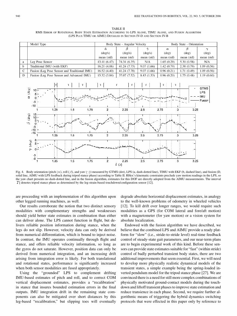
B. Performance Evaluation of Rotational State
Table II presents the rms difference (mean and standard devi-ation from 10 experimental runs) between the GTMS output andeach of four alternative algorithms (filtering only the LPS data,only the TIMU, or fusion of data from both the LPS and TIMUor AIMU) for all six rotational states, including body orientationin pitch , roll , yaw , and their derivatives ( ).The LPS alone offers good orientation estimation in the tripodstance phase [12]. However, its performance in overall jogginglocomotion is poor due to the absence of output throughout theremaining three phases, where state estimates are simply pre-dictions from a very imperfect model applied to those estimatedat takeoff. This distinction is evident in Fig. 4, a plot of the fourtraces (those of the GTMS and the three algorithms) over onestride of one of the runs. The LPS-based estimates match wellthe GTMS data during stance , but do fail to track in theremaining phases. In contrast, the TIMU alone exhibits good an-gular velocity estimates, but suffers the expected drift in angularposition accuracy in consequence of blind integration. These
complementary strengths and weaknesses are nicely exploitedby the fused algorithm in which the LPS acts as a “recalibra-tion” mechanism during the tripod stance phase to kill the driftin the IMU computation, yielding the significant improvementof the orientation estimates. Moreover, with the contribution ofadditional angular acceleration data,5 fusion system further im-proves the performance of velocity estimates.6
C. Performance Evaluation of Translational State
Table III presents the rms difference (mean and standard de-viation from 10 experimental runs) between the GTMS outputand the same three alternative algorithms (filtering only the LPSdata, only the TIMU, and fusion of the LPS and IMU mea-surements)7 for all 6-DOF translational body states, includingCOM displacement in lateral , fore/aft , verticaldirections, and their derivatives ( ). Fig. 5 plots COMdisplacement estimates produced by each algorithm and GTMS(dot) for one of the typical experimental runs. Estimates pro-duced by filtering only the LPS data (dash-dotted line) exhibitperformance that is good in displacement, but poor in velocity,due to the noise-amplifying differentiation it entails. Thoughperformance of velocity estimation by IMU only in Table IIIseems to be similar to that by LPS in consequence of integra-tion error, Fig. 5 does reveal good tracking ability in the velocitystate from IMU (slope or high-frequency components in plot,especially noticeable in in Fig. 5). This further suggests thatwith proper “recalibration” to kill the integration error, the IMUwill deliver better velocity estimation. Thus, the dramaticallydifferent strengths of these two sensors provide the underlyingmotivation for fusing sensor data in the first place, with the an-ticipated improvements in performance.8
VI. CONCLUSION
We have developed a hybrid full 12-DOF body state estimatorfor a hexapod robot executing a steady jogging gait with a sig-nificant aerial phase. The estimator is presently implementedoffline on data collected by a low-cost MEMS-based IMU and anovel leg-strain-based body pose estimator installed on a copyof the robot RHex [2]. The proper fusion of these data yieldstate estimates that agree with measurements taken by an off-board GTMS (up to its noise floor), whereas, in contrast, nei-ther sensing modality yields comparable accuracy when used inisolation. The associated computational costs are not excessive,and the algorithm is now ready for online implementation onRHex in conjunction with more aggressive state-based feedbackcontrollers [11], [26]. The sensor suite is quite generic, and we
5More detailed comparisons of results formed using angular acceleration datafrom the AIMU against results using angular velocity from gyro only can befound in [25].
6Although there is no algorithmic obstacle to fusing yaw data, RHex kine-matics precludes yaw output from the LPS, so the fused filter actually producesyaw and yaw velocity estimates directly from the AIMU.
7Recall that the AIMU differs from the TIMU by incorporating extra angularacceleration data, whereas for the translational state, these two systems are thesame.
8Instead of the constant acceleration model, in the aerial phase, we alsoevaluate the performance of a physical-based ballistic model which, expectably,results in similar performance. This further confirms correct calibration andgravity compensation of accelerometers, since measurement of accelerationshould show “ballistic flight” in the aerial phase [25].
940 IEEE TRANSACTIONS ON ROBOTICS, VOL. 22, NO. 5, OCTOBER 2006
TABLE IIRMS ERROR OF ROTATIONAL BODY STATE ESTIMATION ACCORDING TO LPS ALONE, TIMU ALONE, AND FUSION ALGORITHM
(LPS PLUS TIMU OR AIMU) DETAILED IN SECTION IV-D AND SECTION IV-B
Fig. 4. Body orientation (pitch (�), roll (�), and yaw ( )) measured by GTMS (dot), LPS (a, dash-dotted line), TIMU with EKF (b, dashed line), and fusion (D,solid line, AIMU with LPS feedback during tripod stance phase) according to Table II. RHex’s kinematic constraints preclude yaw motion readings in the LPS, sothe yaw chart presents no dash-dotted line, and in the fusion algorithm, estimates for this DOF are directly adopted from the AIMU measurements. The intervaljT j denotes tripod stance phase as determined by the leg-strain-based touchdown/configuration sensor [12].
are proceeding with an implementation of this algorithm uponother legged running machines, as well.
Our results corroborate the notion that two distinct sensorymodalities with complementary strengths and weaknessesshould yield better state estimates in combination than eithercan deliver alone. The LPS cannot function in flight, but de-livers reliable position information during stance, when thelegs do not slip. However, velocity data can only be derivedfrom numerical differentiation, which is bound to inject noise.In contrast, the IMU operates continually through flight andstance, and offers reliable velocity information, so long asthe gyros do not saturate. However, position data can only bederived from numerical integration, and an increasing driftarising from integration error is likely. For both translationaland rotational states, performance is significantly increasedwhen both sensor modalities are fused appropriately.
Using the “grounded” LPS to complement driftingIMU-based estimates of pitch and roll, and to correct COMvertical displacement estimates, provides a “recalibration”in stance that insures bounded estimation errors in the finaloutputs. IMU integration drift in the remaining state com-ponents can also be mitigated over short distances by thisleg-based “recalibration,” but slipping toes will eventually
degrade absolute horizontal displacement estimates, in analogyto the well-known problems of odometry in wheeled vehicles[12]. To kill drift over longer ranges, we would require suchmodalities as a GPS (for COM lateral and fore/aft motion)with a magnetometer (for yaw motion) or a vision system forabsolute localization.
Endowed with the fusion algorithm we have described, webelieve that the combined LPS and AIMU provide a ready plat-form for “slow” (i.e., stride-to-stride level) real-time feedbackcontrol of steady-state gait parameters, and our near-term plansare to begin experimental work of this kind. Before these sen-sors can provide state estimates suitable for “fast” (within stride)control of badly perturbed transient body states, there are twoadditional improvements that seem essential. First, we will needto develop more physically realistic dynamical models of thetransient states, a simple example being the spring-loaded in-verted pendulum model for the tripod stance phase [27]. We areconvinced there is a need for still more complex combinations ofphysically motivated ground-contact models during the touch-down and liftoff transient phases to improve state estimation andreduce transience in each phase. Second, we require further al-gorithmic means of triggering the hybrid dynamics switchingprotocols that were effected in this paper only by reference to

LIN et al.: SENSOR DATA FUSION FOR BODY STATE ESTIMATION 941
TABLE IIIRMS ERROR OF TRANSLATIONAL BODY STATE ESTIMATION ACCORDING TO LPS ALONE, IMU ALONE, AND
FUSION ALGORITHM DETAILED IN SECTION IV-D AND SECTION IV-C
Fig. 5. Translational COM displacement [lateral (r ), fore/aft (r ), and vertical (r )] measured by GTMS (dot), LPS (a, dash-dotted line), IMU with KF (b,dashed line), and fusion algorithm (D, solid line) according to Table III. The interval jT j denotes tripod stance phase determined by the leg-strain-based touchdown/configuration sensor [12].
the LPS’s cues. We believe that the interacting multiple modelapproach [28] holds significant promise in this context.
APPENDIX IANALYSIS OF A 12-AXIS ACCELEROMETER SUITE
A. Angular Velocity From 12-Axis Accelerometer Suite
The process to obtain an invertible mapping for this quadraticsystem from to cannot be solved kinematically by thesix available equations alone, since there exists at least one signambiguity for the unknowns. However, this is feasible, given theinitial condition along with the availability of angular accelera-tion derived from the other six equations in the same 12-axis ac-celerometer suite. Without loss of generality, assuming at timethe state of angular acceleration and angular velocity are avail-able, the procedure to solve angular velocity at is as fol-lows. First, derive “estimated” angular velocity by angular ve-locity and angular acceleration at using a constant acceler-ation model. Second, adopt the sign of this estimated angularvelocity as the correct sign identification for angular velocity at
. Finally, choose three scalar components from solved ,either or , where , , to solveangular velocity , or combine both to construct a completesquare and solve the “fused”angular velocity.
B. Structure Matrix
Without loss of generality, consider the shape of the robotbody as a “rectangular prism” and the availability of space in-side it. Numerical exploration reveals the condition number ofthe structure matrix is minimized when four 3-axis ac-celerometer packages occupy four of eight corners of this prismwith specific and equal distances, as well as when the geomet-rical center of the prism coincides with the COM, as shown inFig. 6.
The “best” condition number can be achieved in RHex’s bodysize (25 cm 50 cm 15 cm) is 13.33. However, the practical im-plementation of the accelerometer suite within the limited avail-able space left in RHex, as well as having been designed to RHexto keep COM low (does not matching geometrical center) forstability, yields the high condition number of 41 in the currentsetup. From singular value decomposition of the structure ma-trix , we observe that the subspaces spanned by small sin-gular values are those that effectively span the last four elementson unknown vector in (3), resulting in deteriorating theestimation of angular velocity. Therefore, we adopt the gyro’soutput as the only data source of angular velocity .
C. Short Discussion
Since in current practical implementation, we need the extra3-axis gyro to provide angular velocity data due to an ill-struc-

942 IEEE TRANSACTIONS ON ROBOTICS, VOL. 22, NO. 5, OCTOBER 2006
Fig. 6. Ideal locations of four 3-axis accelerometer suites with respect to theCOM.
tured matrix, we attempt an alternate method of applying 6-axisaccelerometer suite data and 3-axis gyro data into the right-handside of rearranged dynamic equation (2)
and to solve linear and angular acceleration on the left-hand sideby constructing a new 6 6 “structure” matrix , where
and operate the matrix inverse. This newstructure matrix is only nonsingular if the 6-axis accel-eration is measured from at least three locations. However, thisindicates that the coupled calibration detailed in Appendix II,used to compensate the misaligned installation error, is not fea-sible unless all locations have 3-axis acceleration measures (atleast 9-axis total). In this situation, we prefer to install yet an-other 3-axis acceleration measure (12 total) to let the computa-tion of linear/angular acceleration remain independent of gyromeasurement. We can now treat angular acceleration and an-gular velocity as two independent sensing data to incorporateinto the EKF, detailed in Section IV-A.
APPENDIX IICOUPLED CALIBRATION
Theoretically, acceleration along a specific direction (usuallythe principal axis of the body frame; ex: ) can be obtainedby a 1-axis accelerometer installed on the body framewith known body orientation ( ), as shown in Fig. 7,left. From the reverse point of view, the sensor readingdepends on body orientation and acceleration of that specificdirection only (ex: ). However, in practical implementation,the misalignment between desired and measured directionsdue to installation error causes the sensor reading to bedependent on the acceleration along all three principal axesshown in Fig. 7, left: .For this reason, in the general case, a 3-DOF accelerationreading is required for a single accelerationalong a specific direction (ex: ). If only one accelerom-eter measurement is applied, the acceleration measurement
Fig. 7. Left: sketch of misalignment between accelerometer measuring di-rections (� ; � ; � ) and principal axes. Right: sketch of acceleration measurealong z by a misaligned accelerometer � .
in the specified direction will be contaminated by the ac-celeration in the remaining two directions. This practicalconcern motivates us to use a 3-axis accelerometer suite asthe basic unit for acceleration measurement, which allows usto construct a 3-DOF coupled mapping from sensor space toorthogonal acceleration space along three principal axeswith known body orientation, expressed in the general form
.Considering the case that acceleration is measured
by only one misaligned 1-axis accelerometer pointingshown in Fig. 7, right,
the percentage error (%) of measuring is given by
. In the case of , (only 5 misalignment)and (acceleration has the same range along withthree orthogonal components), the percentage error is 11.9%.The error will increase greatly when the range of accelerationdue to motion is much less than that due to gravity. For ex-ample, if , (the same, only 5 misalignment)and (assume gravity is along the direction of
and the range of acceleration due to motion is only 20% ofgravity), then the percentage error goes up to 36.5%.
ACKNOWLEDGMENT
The authors would like to thank S. Skaff and A. Rizzi forseveral useful discussions. They thank G. Sharp for his GTMSimplementation. Also, they thank J. Weingarten and J. Raisanenfor jogging gait tuning.
REFERENCES
[1] M. Buehler, U. Saranli, and D. E. Koditschek, “Single actuator per legrobotic hexapod,” U.S. Patent 6 481 513, 2002, McGill Univ., Regentsof the Univ. Michigan.
[2] U. Saranli, M. Buehler, and D. E. Koditschek, “Rhex—A simple andhighly mobile hexapod robot,” Int. J. Robot. Res., vol. 20, no. 7, pp.616–631, 2001.
[3] J. D. Weingarten, G. A. Lopes, and D. E. Koditschek, “Automated gaitgeneration and optimization for legged robots,” in Proc. IEEE Int. Conf.Robot. Autom., 2004, vol. 3, pp. 2153–2158.
[4] E. Z. Moore and M. Buehler, “Stable stair climbing in a simplehexapod,” in 4th Int. Conf. Climbing, Walking Robots, 2001, pp.603–610.
[5] D. Campbell and M. Buehler, “Stair descent in the simple hexapod‘RHex’,” in Proc. IEEE Int. Conf. Robot. Autom., 2003, vol. 1, pp.1380–1385.
[6] H. Komsuoglu, D. McMordie, U. Saranli, N. Moore, M. Buehler, andD. E. Koditschek, “Proprioception based behavioral advances in ahexapod robot,” in Proc. IEEE Int. Conf. Robot. Autom., Seoul, Korea,2001, vol. 4, pp. 3650–3655.
LIN et al.: SENSOR DATA FUSION FOR BODY STATE ESTIMATION 943
[7] J. D. Weingarten, R. E. Groff, and D. E. Koditschek, “A framework forthe coordination of legged robot gaits,” in Proc. IEEE Int. Conf. Robot.,Autom., Mechatron., 2004, pp. 679–686.
[8] U. Saranli, A. Rizzi, and D. Koditschek, “Model-based dynamic self-righting maneuvers for a hexapedal robot,” Int. J. Robot. Res., vol. 23,no. 9, pp. 903–918, 2004.
[9] N. Neville and M. Buehler, “Towards bipedal running of a six leggedrobot,” in Proc. 12th Yale Workshop Adaptive, Learning Syst., May2003.
[10] D. McMordie and M. Buehler, “Towards pronking with a hexapodrobot,” in Proc. 4th Int. Conf. Climbing, Walking Robots, 2001, pp.659–666.
[11] U. Saranli, “Dynamic locomotion in a hexapod robot,” Ph.D. disserta-tion, Univ. Michigan, Ann Arbor, Aug. 2002.
[12] P. Lin, H. Komsuoglu, and D. E. Koditschek, “A leg configuration mea-surement system for full body pose estimates in a hexapod robot,” IEEETrans. Robot., vol. 21, no. 3, pp. 411–422, Jun., 2005.
[13] R. Altendorfer, N. Moore, H. Komsuoglu, H. B. Brown, D. McMordie,U. Saranli, R. Full, and D. E. Koditschek, “RHex: A biologically in-spired hexapod runner,” Auton. Robots, vol. 11, no. 3, pp. 207–213,2001.
[14] P. Lin, H. Komsuoglu, and D. E. Koditschek, “Toward a 6-DOF bodystate estimator for a hexapod robot with dynamical gaits,” in Proc.IEEE/RSJ Int. Conf. Intell. Robots Syst., 2004, pp. 2265–2270.
[15] B. Barshan and H. F. Durrant-Whyte, “Inertial navigation systems formobile robots,” IEEE Trans. Robot. Autom., vol. 11, no. 3, pp. 328–342,Jun. 1995.
[16] A. J. Padgaonkar, K. W. Krieger, and A. I. King, “Measurement of an-gular accelerarion of a rigid body using linear accelerometers,” Trans.ASME, vol. 42, pp. 552–556, 1975.
[17] P. J. Escamilla-Ambrosio and N. Mort, “A hybrid Kalman filter–fuzzylogic architecture for multisensor data fusion,” in Proc. Int. Symp. In-tell. Control, 2001, pp. 364–369.
[18] M. Abdelrahman and P. Abdelrahman, “Integration of multiple sensorfusion in controlled design,” in Proc. Amer. Control Conf., 2002, pp.2609–2614.
[19] S. Sukkarieh, E. M. Nebot, and H. F. Durrant-Whyte, “A high-integrityIMU/GPS navigation loop for autonomous land vehicle application,”IEEE Trans. Robot. Autom., vol. 15, no. 3, pp. 572–578, Jun. 1999.
[20] G. Dissanayaka, S. Sukkarieh, E. M. Nebot, and H. F. Durrant-Whyte,“The aiding of a low-cost strapdown inertial measurement unit usingvehicle model constraints for land vehicle applications,” IEEE Trans.Robot. Autom., vol. 17, no. 5, pp. 731–747, Oct. 2001.
[21] S. I. Roumeliotis, A. E. Johnson, and J. F. Montgomery, “Augmentinginertial navigation with image-based motion estimation,” in Proc. IEEEInt. Conf. Robot. Autom., 2002, vol. 4, pp. 4326–4333.
[22] O. Wijk and H. I. Christensen, “Triangulation-based fusion of sonardata with application in robot pose tracking,” IEEE Trans. Robot.Autom., vol. 16, no. 6, pp. 740–752, Dec. 2000.
[23] R. C. Ren, S. H. Phang, and K. L. Su, “Multilevel multisensor baseddecision fusion for intelligent animal robot,” in Proc. IEEE Int. Conf.Robot. Autom., 2001, vol. 4, pp. 4226–4231.
[24] G. C. Sharp, Univ. Michigan, “Ground Truth Measurement System.”(2003) [Online]. Available: http://www.sourceforge.net/projects/gtms/
[25] P. Lin, “Proprioceptive sensing for a legged robot,” Ph.D. dissertation,Univ. Michigan, Ann Arbor, Aug. 2005.
[26] U. Saranli and D. E. Koditschek, “Template based control of hexapedalrunning,” in Proc. IEEE Int. Conf. Robot. Autom., 2003, vol. 1, pp.1374–1379.
[27] R. Altendorfer, D. E. Koditschek, and P. Holmes, “Stability analysisof a clock-driven rigid-body slip model for RHex,” Int. J. Robot. Res.,vol. 23, no. 11, pp. 1001–1012, 2004.
[28] S. Skaff, A. Rizzi, H. Choset, and P. Lin, “Context-based state esti-mation technique for hybrid systems,” in Proc. IEEE Int. Conf. Robot.Autom., Apr. 2005, pp. 3935–3940.
Pei-Chun Lin (S’02–M’05) received the B.S.and M.S. degrees in mechanical engineering fromNational Taiwan University (NTU), Taipei, Taiwan,R.O.C., in 1996 and 1998, respectively, and the M.S.degree in electrical engineering and computer sci-ence and the Ph.D. degree in mechanical engineeringfrom The University of Michigan, Ann Arbor, in2005.
Currently, he is a Postdoctoral Research Fellowwith the University of Pennsylvania, Philadelphia.His research interests include mechanical design,
sensor design, sensor fusion, and analysis of robot dynamic behaviors.
Haldun Komsuoglu (S’95–M’04) received the B.S.degree from the Department of Electrical and Elec-tronics Engineering, Middle East Technical Univer-sity (METU), Ankara, Turkey, in 1997. He receivedthe M.S. degree in 1998 with a controls major andthe Ph.D. degree in 2004, with a dissertation enti-tled “Toward a formal framework for open-loop con-trol of rhythmic tasks,” from the Department of Elec-trical Engineering and Computer Science, Universityof Michigan, Ann Arbor.
His research interests include open-loop control ofhybrid dynamical systems, design and characterization of self-stabilizing mech-anisms with applications in legged locomotion, as well as design of embeddedsensory and actuation systems for robotic platforms.
Daniel E. Koditschek (S’80–M’83–SM’93–F’04)received the Ph.D. degree in electrical engineeringfrom Yale University, New Haven, CT, in 1983.
He served on the faculty of the Department ofElectrical Engineering, Yale University, for 10years, and then joined the Department of ElectricalEngineering and Computer Science, University ofMichigan, Ann Arbor, in 1993. He joined the Univer-sity of Pennsylvania, Philadelphia, in January 2005,where he holds secondary appointments with theDepartments of Computer and Information Science
and Mechanical Engineering and Applied Mechanics. He is also the AlfredFitler Moore Professor and Chairman of Electrical and Systems Engineering atthe School of Engineering and Applied Science. His research interests includerobotics, the application of dynamical systems theory to intelligent machines,and nonlinear control.


![Distributed Dimensionality Reduction Fusion Estimation with ...1802.03122v1 [cs.SY] 9 Feb 2018 1 Distributed Dimensionality Reduction Fusion Estimation with Communication Delays in](https://img.dokumen.tips/doc/110x75/5adb5b417f8b9a6d7e8ddabc/distributed-dimensionality-reduction-fusion-estimation-with-180203122v1-cssy.jpg)