Embed Size (px)
Citation preview

Sonic Degassing of Paper Pulp
Paper Mill Modification Members:
Matthew FergusonAustin Sims
William StaffordJohn Troxell
Submitted to:
Dr. Mir AtiqullahAdvisor
on
December 4, 2015
ME 4202: Senior Design IIFall, 2015
Mechanical Engineering DepartmentKennesaw State UniversityMarietta Campus, Marietta GA.
Table of Contents

1
Abstract
1.0 Introduction
1.1 Background information
Initial Needs/Design Statement
Initial Design Statement
2.0 Customer Needs Assessment
2.1 Weighing of Customer Requirements
3.0 Revised Needs Statement and Target Specifications
4.0 External Search
4.1 Benchmarking
4.2 Applicable Patents
4.3 Applicable Standards
4.4 Applicable Constraints
4.5 Business Opportunity
5.0 Concept Generation
5.1 Problem Clarification
5.2 Concept Generation Process
5.3 Initial Screening
6.0 Concept Selection
6.1 Concept Screening
6.2 Concept Development, Scoring, and Selection
6.3 Data and Calculations for Feasibility and Effectiveness Analysis
7.0 Final design
7.1 Capabilities and Functionality
7.2 Design Revisions
7.3 Materials Research and Selection
7.4 Manufacturing, Assembly, and Cost
7.5 Cost Analysis
7.4 Design Drawings, Parts List, and Bill of Materials

2
7.5 Design Validation
7.6 Finite Element Analysis/Simulation
7.7 Prototype Test
8.0 Conclusions
Acknowledgement
References
Appendices

3
Abstract
When the felt, that holds liquid paper in place, travels around the forming rolls of the wet
end of the machine, some of the stock, aka liquid paper, is lifting off of the felt and striking the
next layer of stock being applied that is traveling out of the head box (applicator of stock) and
along the surface of the forming roll (which removes water). This causes quality issues that not
only result in quality claims by the customer, but can also be severe enough to cause the paper
sheet to break further in the system, causing lost time. After using a high-speed camera to
observe the stock lifting from the forming rolls, it was found that the stock is always lifting at
locations where air bubbles are present in the stock. These air bubbles create a weak point in the
surface of the stock, allowing some of it to separate due to the angular velocity created by
passing around the roll. These bubbles are caused by various turbulent points in the stock
preparation and runoff recovery systems, so the company in question focused on eliminating the
bubbles after the stock has been applied to the felt.
Figure 1: Slinging on Forming Cylinder

4
The engineers at the paper mill in San Jose have attempted to implement a wipe system to
eliminate the bubbles. However, dried stock builds up on the wipe very quickly, which causes
more defects than it eliminates after approximately 30 minutes of operation.
In order to eliminate the bubbles without affecting the formation of the stock, we are
proposing the use of a sonic system to pop the bubbles that are both on the surface and still
trapped within the layers of stock. The system will consist of directed sound emitters suspended
close to the stock, emitting a specific sound profile. This system aims to vibrate both the fluid
and the felt below to cause slight variations in the velocity of the fluid at different depths. These
variations in velocity will create shear stresses that will overcome the surface tension of the
bubbles, causing them to collapse and separate into smaller bubbles. These smaller bubbles will
then collapse in a similar way until they are either small enough to not cause any slinging of the
stock, or will make their way to the surface of the solution and escape before reaching the point
of the roll where they can cause stock to sling.

5
1.0 Introduction
1.1 Background information
The ultimate goal of the papermaking process is to take a slurry-like mix of 98% water
and 2% dissolved paper pulp, called stock, and dry it into commercial paper. This drying is done
by applying the paper stock to a mesh of woven fibers that have been waterproofed with a
polymer coating, referred to as the felt. The felt is passed through a series of hot rolls called drier
cans, to evaporate off the excess water. This section of the machine is known as the ‘Dry End’,
and is not within the scope of our project. We will focus on solving a problem in the wet end
because this is where the slinging issue occurs.
This specific type of paper machine, known as a forming cylinder machine, applies the
stock to the felt in eight layers. Other machines could have as few as two applicators. The area
in which the stock is applied is known as the wet end. Aside from the first layer, each of the next
seven layers is applied in an identical fashion to the first. Those next seven layers are applied by
applicators known as head boxes, which are suspended above seven different forming rolls
throughout the wet end. The stock exits the head box via a uniform slit at the bottom of the head
box. The width of this slit spans just short of the width of the felt (roughly 138 inches) . At each
instance of the time of stock application, the felt is traveling around a cylinder, known as the
forming rolls (FR).
The forming roll is, from a side view of the machine (where the wet end is on the left and
the dry end is on the right) located to the left of the outlet of the head box. The new layer of
stock is applied to the forming cylinder (FC) - a different roll which is located directly under the

6
head box. The new stock travels a short distance along the forming cylinder before being
squeezed between the forming cylinder and the felt, pushing the new layer of stock against the
previously-placed layer. The felt then circles this roll before being squeezed between the forming
cylinder and a third roll, known as the couch roll (CR), pronounced “cooch roll”. The felt then
follows this roll part of the way around and travels up to the next forming roll, and the cycle is
repeated.
The significant differences in the first head box system are that 1) the head box faces in
the opposite direction from the others and 2) there is no forming roll or forming roll, only a roll
to redirect the felt.
(Note: see appendix ‘A’ for a visual representation of this stage, referencing the 2 letter
abbreviations. Courtesy of Graphic Packaging International)
1.2 Initial Needs/Design Statement
Our objective, given by Graphic Packaging International, is to reduce the slinging to a
great enough degree that the speed of the paper machine can be increased from 680 feet per
minute to at least 715 feet per minute. The machine is capable of running up to 740 feet per
minute but is meant to be run at 500 feet per minute; the slinging problem is the one limiting
factor preventing the machine from running faster. The solution must also cost under $40,000.
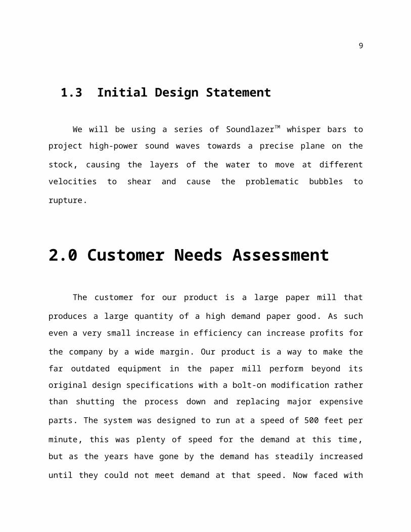
1.3 Initial Design Statement

7
We will be using a series of SoundlazerTM whisper bars to project high-power sound
waves towards a precise plane on the stock, causing the layers of the water to move at different
velocities to shear and cause the problematic bubbles to rupture.
2.0 Customer Needs Assessment
The customer for our product is a large paper mill that produces a large quantity of a high
demand paper good. As such even a very small increase in efficiency can increase profits for the
company by a wide margin. Our product is a way to make the far outdated equipment in the
paper mill perform beyond its original design specifications with a bolt-on modification rather
than shutting the process down and replacing major expensive parts. The system was designed to
run at a speed of 500 feet per minute, this was plenty of speed for the demand at this time, but as
the years have gone by the demand has steadily increased until they could not meet demand at
that speed. Now faced with needing more speed without time to purchase a newer machine with
a higher top speed, they pushed the machine they had past the designed production speed. At
speeds of over 680 feet per minute, they began having quality problems as well as sheet breaks
due to bubbles forming from running the pump and felt at such a high speed. The customer
wants to increase the speed to 715 Feet per minute.Using a device that prevents problematic bubbles without extensive modification to the
machine or its working components is a must if the company aims to run the machine at its
highest speed of 715 feet per minute. The stated need is around an extra 35 feet per minute which
could generate another 2 million dollars for the company per year. The need therefore, is to
either allow the full speed increase with only as many problems as they face now or to reduce the
number of issues faced at the current speed. The ideal goal is to reduce the amount of issues as
well as increasing the speed though unnecessary, if achieved we can increase the budget
allowed.

8
2.1 Weighing of Customer Requirements
As far as our customer is concerned there are three main requirements, namely increase
in efficiency, increase in speed, and reasonable cost. These three requirements can be met in
various ways to resolve the needs of the mill and allow for a wide variety of solutions. This
offered the team many paths to choose from.
The highest priority is cost in that making a ridiculously high price tag to solve a less
costly problem will have the mill reject our idea outright. However, the cost is flexible
depending on how well we can meet the other two requirements. This cost can be reduced
greatly by focusing on making a design they can make in house this is why we felt it was
necessary to design the project to this mill’s specific needs and supplies. That way we match the
needs at least with room to profit for us. It also gives us more potential customers as we can
custom design a solution for any mill.
The secondary need is for speed, as the speed increase is the reason our project is needed. The Mill holds this at second place because even if we only allow them to have as many
problems as they do now at a higher speed it will be worth the $40,000 we are budgeting for the
project. This was the original number for the bare minimum of solutions to the problem
presented. If we allow them even faster than they want or with higher quality then it will be
worth more to the mill giving us a bigger profit margin. We are hoping to exceed the bare
requirement for speed by a wide margin just to help make sure we can actually maintain this idea
and see our solution be fruitful.
Finally there is efficiency, though this efficiency can be quantified in many different
ways. One way is improving the quality of the paper produced so they don’t need to speed up as
9
more of the product they produce is of sellable quality. Also if we can allow the quality to go up
as well as increasing the speed we will far exceed the worth of our product and grant us more
pricing options. However, the efficiency is ironically the lowest priority as we could not improve
the efficiency at all and still meet, or even exceed the customer requirements.
3.0 Revised Needs Statement and Target
Specifications
The original core customer requirements have remained the same but the specifics have
been modified significantly from where they started. In the beginning we were told by the mill
that it was turbulence in the stock causing the flinging and we had to try and find a way to make
the stock more laminar. This involved quite a bit of calculation to discover an approximate
Reynolds number and how much we would have to change to result in a laminar flow of the
stock. However, as we had our group members travel to the mill to get a better idea of what was
really happening the mill provided us with the true problem was bubbles created by running the
system beyond the specifications it was designed for. This completely changed the needs of the
customer, though still seeking to increase at least the speed but also efficiency and quality of the
paper, the method would have to change.
The altered specifications list is as follows:
1. The speed of the felt is 700 feet per minute
2. The average viscosity of the pulp is a kinematic viscosity of whitewater: 0.7-1.0 centistokes
3. A sheet break resulting from the flinging occurs about 8 times per month, 30 minutes per
incident
4. The forming roll is 72 inches in diameter, 19 inches on the couch roll

10
5. The base weight is 62 lbs/1000 square feet
6. The web width is 150 inches
7. The vertical clearance for the wipe is 8 inches
8. The vacuum strength of the forming cylinder is 1.4in water column, and 0 on the couch roll
9. The length of felt between the meeting point of the two rolls and where the current wipe is
located 4 feet
10. The thickness of paper, where 14 point paper is the primary product, and is 0.014 inches
11. The temperature of the stock when it's applied to the felt is120F
12. The maximum cost for the design is $40,000
13. The current hours needed to repair/clean wipe and (rough) frequency of cleaning is 20
minutes to clean every 18-20 hours
14. The concentration at the head box is roughly 1.2% stock, 98.8%
15. The limiting factor above wipe is the head box
16. The ambient humidity is 100%
17. The vibrations of nearby bearings indicate 0 frame vibration (Emerson vibration
instrumentation)
We had already settled on the possible idea using acoustics for whatever solution we
could come up with for the minimal effect it would have on the formation of the paper fibers
flowing in the stock. When it came to popping bubbles we had to research if it was possible to do
so with sound waves. Not to mention we had to be sure our system was not already made now
that the precise purpose had changed so much. We have to now have bubble popping as our
highest priority as the bubbles are allowing stock an easy route to lift up off the felt and continue
moving forward as the angular velocity changes around the roll. Our criterion is to allow the
machine to run faster than it is now while maintaining the amount of troubles they are facing. Though not as important another need we assessed is to reduce the quality issues as well as speed
up the machine to squeeze the most effectiveness as possible, and add as much worth in the

11
product as we can. However, we must insure we do not cause a different quality concern with the
introduction of our sonic power being introduced.
4.0 External Search
The exact layout of the paper machine we have been investigating is very unique; only
two of these specific machines, manufactured by Kobayashi, are still running today. This
machine is an inverted fourdrinier paper machine. In most fourdrinier paper machines, the felt
runs underneath the wet end rolls. In this machine, the felt runs over the top of the wet und rolls.
Therefore, the exact dimensions that we develop will not carry over to different facilities, but by
altering the support structure, the premise of this design can be applied to other inverted
fourdrinier paper machines
The exact source of the problem remained unclear, so through the aid of Facility
Integrations, a maintenance consulting firm, Matthew Ferguson and John Troxell were provided
with a flight and accommodations at the Graphic Packaging Santa Clara mill, as well as
introductions to various employees at different levels. These included mill manager Jose,
maintenance personnel Terry Barker and Joel Sanchez, and production manager, Jeff Mih.
Through their assistance, we were able to clear up various misunderstandings about the problem
and were able to narrow down our design ideas to the sonic system.
Once the bubbles had been identified as the source of the problem, we looked into the
details behind the cause of the bubbles. During the trip to California, we spoke with Jose, the
mill manager, about what he thought the causes of the bubbles were. He assured us that the cause
of the bubbles was not a concern, but rather, the bubbles needed to be popped after the stock had
left the head box. We then spoke with Terry, who is mostly responsible for maintenance in the

12
coating section, but who had worked there a long time and was very familiar with the whole
system. He walked us through the process in more detail and gave us a more real perspective on
what was happening. We discovered that the bubbles are introduced to the system from a number
of sources – turbulence from the runoff recovery system, air injected by the positive
displacement pump used to bring the water up to the head box, air stirred into the stock when it’s
first being broken down from recycled paper, and potentially other source that we may have
missed. Therefore, Jose’s was correct in saying that the bubbles would be best dealt with after
the stock had exited the head box.
4.1 Benchmarking
At this point in time there is really no competition to our device to improve quality and
productivity at the machine speeds the mill needs to run at. When we began this project the paper
mill had placed a wipe system in an attempt to counteract the bubbling of the stock. We believed
that would be the competing design, which was cheap and initially showed promise. However, as of this semester the wipe was removed as it was beginning to cause more harm than good as
well as adding a cleaning job to perform. As such we only have the standard machine
performance at the current running speed with whatever performance the machine has at the
desired speed to compare to. This is actually a complication for our designing as we must
calculate the savings our product will create and see how we can reduce cost to the customer
while maintaining profit for our potential manufacturer and ourselves without any real set point
to gauge off of.

13
4.2 Applicable Patents
For the project we will be using the SoundLazer ™ system as designing a whole new
sonic oscillator would be a senior design project all its own. Also the SoundLazer system will be
able to perform the task quite well for not being specifically designed for this purpose. They
meet many of our specifications for safety, functionality, and power. Therefore, we will keep in
close contact with the SoundLazer Company and perhaps even partner with them should this
project lead to a business venture.
4.3 Applicable Standards
As this device will be installed in an industrial worksite we will have many standards. OSHA standards will need to be at least met but hopefully significantly exceeded to avoid the
standard being tightened and needing a complete overhaul of our design. Along with that we
need to meet or exceed the Mill’s safety standards, which are often more strict than those of
OSHA. This was a considerable factor in our design process as we knew the seriousness of
dealing with safety standards, and the potential repercussions of not understanding fully and
following these standards in an industrial setting.
For OSHA we must comply with the sound pollution standard as follows.1910.95(a)
Protection against the effects of noise exposure shall be provided when the sound levels
exceed those shown in Table G-16 when measured on the A scale of a standard sound level
meter at slow response. When noise levels are determined by octave band analysis, the
equivalent A-weighted sound level may be determined as follows:

14
Equivalent sound level contours. Octave band sound pressure levels may be converted to
the equivalent A-weighted sound level by plotting them on this graph and noting the A-weighted
sound level corresponding to the point of highest penetration into the sound level contours. This
equivalent A-weighted sound level, which may differ from the actual A-weighted sound level of
the noise, is used to determine exposure limits from Table 1.G-16. Additionally, we made sure

15
our cleaning procedure does not force people to breach any climbing standard, work standard,
chemical standard, or PPE standard.
Cleaning and working: 1910.22(b)(1)
Where mechanical handling equipment is used, sufficient safe clearances shall be
allowed for aisles, at loading docks, through doorways and wherever turns or passage must be
made. Aisles and passageways shall be kept clear and in good repairs, with no obstruction across
or in aisles that could create a hazard.
PPE: 1910.132(a)
Application. Protective equipment, including personal protective equipment for eyes,
face, head, and extremities, protective clothing, respiratory devices, and protective shields and
barriers, shall be provided, used, and maintained in a sanitary and reliable condition wherever it
is necessary by reason of hazards of processes or environment, chemical hazards, radiological
hazards, or mechanical irritants encountered in a manner capable of causing injury or impairment
in the function of any part of the body through absorption, inhalation or physical contact.
4.4 Applicable Constraints
The constraints for this project come in various formats from mechanical, financial, and
even power constraints. As with all design projects these were a set of hurdles we had to
overcome but in our case it was especially important because it set a precedent for one of our
potential business models. We also learned though constraints often limit your ability to resolve

16
a problem they also allow you to focus your design into a coherent project and allow you to
remove suggested designs.
First we had some obvious mechanical constraints such as the height we have to work in . This was actually our only purely negative constraint as it left us with very little room to work
with and a large span of felt to cover. Also with how tight the spacing is we are at high risk of
buildup and corrosion from the extreme environment inside the machine. Along with that we had
to come up with a way to mount our design as heavy as it will be to something sturdy enough to
hold the weight while it oscillates. Another mechanical constraint is in the mechanics of bubbles
where you cannot truly pop a submerged bubble. We have to place our device at point where the
bubbles are at the surface and can be popped and the gas released.
Financially our product has a great market to infiltrate as the paper mill industry is rife
with problems that minimal improvements can save and earn a lot of money. Our product has to
balance on the edge of increasing efficiency and speed while keeping cost underneath the worth. We could really lose a lot of practicality by adding certain expenses that add little to improving
the running of the machine. So we had to make sure we keep that minimal improvement value as
our budget while planning to outperform those minimal specifications. If we can make it for
cheaper and add higher quality to the mill we stand to make higher profit from the customer.
Finally our power constraints are a unique to the papermaking process. At this point in
the process the paper is more a watery slurry that has little floating fibers trying to form into a
coherent grain. As such we must limit the amount of disturbance to these fibers at all cost.
However, we have to have enough power to pop the bubbles on the top of the stock. This
constraint is the worst kind as it has limits on the high end as well as the low end, forcing more
design.

17
4.5 Business Opportunity
Though this project was begun for one paper mill with a specific problem it is a problem
every paper mill with this particular Kobayashi machine will eventually face without replacing
the machine. From the meeting with Jeff Mih, the estimated opportunity was approximately
$1,850,000, as seen in the appendix. On top of that once our device is completed it can be
modified to fit multiple machines with speed constraints due to bubble accumulation from
speeding up the process. With this in mind we even have a market with brand new designs
improving their efficiency “out of the box” as it were. If this design and idea take off it may even
be a design added to all new machines by all companies using this method of stock preparation .
As such the market is full of potential expansion, opening opportunities not only in the paper
industry but also in all industry where bubbles are problematic. The use of sonic waves to pop
bubbles is not new but we are doing it in a way previously unexplored in industry , as such we
may even be able to design a system using sonic waves to perform our task more efficiently
adding acoustics to our field of business. Also as we improve designs for oscillators we improve
the effectiveness of our flagship paper industry products that can be easily replaced as they are
designed to be easy on easy off. Then with improvements on our design in paper industry we can
better focus our acoustic designs to a specific purpose. With this all in mind we feel our project
has great potential to begin a self-fueling business model.
Also we have designed specifically to cater to our specific mill, and the supplies they
have on hand. This greatly reduces cost for the mill and may be an equally effective business
model specially designing models for the mill and selling them the plan. In this model we allow

18
the mill to effectively cut out the middle man and gives us a bigger profit margin with minimal
upfront cost. This model still allows for expansion from improvement on the oscillator at a later
date, as well as allowing our small group to open shop without needing a partner on the business
venture. As such all these options should be weighed equally.
5.0 Concept Generation
In this section, the different possibilities of solving the problem will be discussed.
Several options were explored and removed in Senior Design I. Before a trip was arranged to
San Jose, the cause of the problems, bubbles in the pulp, were unknown to the group. Therefore,
we tried to remove the slinging in other manners as opposed to the final solution. Potential
solutions included drying out the pulp earlier before it reached the location of the problem,
decrease the angular velocity at the point of infraction, or control the turbidity of the stock by
applying a force on the stock.
Methods of accomplishing these goals were thought up which included better dewatering,
less change in direction, shielding, decreasing vertical felt movement, adjusting the speed of the
machine, and sticking the stock to the felt better. Here is the original concept generation list:
1. Methods for preventing splatter onto paper
a. better dewatering
i. physical contact
1. remove excess water
2. create choke point
3. compress the stock

19
4. create more laminar flow
5. hoover dam pillars for lamination
ii. heat
1. resistance
a. direct
i. heat the felt
b. indirect
i. gas
ii. wood fir
iii. nuclear reactor
iv. heat sinks
iii. vacuum
1. actually remove water
a. above the felt
i. proximity
b. below the felt
i. vacuum box below felt
2. hold the stock down more firmly
iv. oscillation
1. mechanical
a. oscillate the felt
b. oscillate any added component
2. acoustical
a. oscillate the felt
b. oscillate any added component
3. using vacuum remove from odd angles to redirect forces
a. vacuum pulled according to sin function (oscillation)
v. weak universal forces
1. sponge
2. reverse gravity (or increase at a point)
b. less change in direction

20
i. increase diameter of the rolls
c. shield
i. shield at beginning of drier section
d. decrease felt movement
i. allow the surface tension the best possible chance to hold together
ii. increase felt rigidity
e. adjust speed
f. stick it the mesh better
i. adjust composition of stock
ii. change material composition of felt
iii. add adhesives later in the process
An initial Screening would weed out options such as using a nuclear reactor to heat the
pulp for a better dewatering. After other obvious removals, e.g. sponges and wood fires, the
following list was what remained for a closer look:
1. Acoustic Oscillation
a. Above the felt
i. Subwoofer
ii. focused sound emitter
b. Horizontal to the felt
i. Reciprocating Subwoofer
ii. Focused sound emitter
2. Mechanical Oscillation of Felt
a. Oscillate the felt
i. Roller underneath
ii. Roller on top of felt
iii. Horizontal felt oscillation
1. Clamping rollers on edge
iv. Oscillate the couch roll
3. Wipe

21
a. Flexible wipe
b. Rigid wipe
4. Compress Stock
a. Compression rollers
5. Pillars
a. Vertical hanging pillars
b. Pillars on felt
6. Indirect water heater
a. Inductive heater
7. Heat Felt
a. Heating coils in felt
Some options were removed that seemed like good ideas, but went against what the
customer would have wanted. Increasing the diameter of the forming roll is a prime example of
this. It would have not only been out of budget, but they have already tried that right before the
last headbox. The San Jose plant stated that although the new roll had a positive effect on the
quality of the paper and the reduction of slinging, it was not as much as they would have liked
and could only be done at the section eight location. The other sections were unviable due to a
lack of real estate.
Using a shield to catch the slinging made it into the viable options. It would not have made it
past this initial screen if we had known that the plant had already implemented one . It worked
well in the spot our group had decided it should have gone.This “Viable Options” list will influence the creations described in the Tables shown in Section
5.3.
5.1 Problem Clarification

22
Figure 2 shows a flowchart that better represents our main goal and how we wish to
accomplish this goal. This flowchart was influenced by the Viable Options list and is used to
influence the Tables shown is Section 5.3.
Figure 2 - Flowchart of how to accomplish decreasing maintenance and increase productivity.
5.2 Concept Generation Process
The main goal of the project is to decrease slinging on the Kobayashi Paper Maker, and
we were given freedom on how to accomplish the goal. The largest restricting factor is a budget
of $40,000 to work with. To accomplish the objective, the group decided that brainstorming
ideas was the best path. The ideas that were generated were:
· Acoustic Oscillation
o This device will be comprised of several subwoofers, or speakers, that will oscillate the
water/stock on the felt. In theory, this should create waves at a frequency opposing that of the
stock and pull the bubbles out of solution. The now larger bubbles will then have enough
buoyancy force to rise to the surface on their own and be ruptured by the sound pressure waves.

23
· Mechanical Oscillation
o This device will be comprised of an oscillating machine that will cause the felt to shake. In
theory through the same way listed above, this should create laminar flow and rupture the
bubbles through vibration.
· Wipe
o The device currently being used is a wipe. It requires maintenance around every 20 hours.
The goal is to create a better wipe that will require less maintenance. The goal of this device is
that it will remove excess water from going into the dryer section by keeping the water on one
side of the wipe, where it will then drain through the felt and pop bubbles both on the surface
and within the stock.
· Compression
o This device will work similar to the wipe. It will be comprised of two rollers where the felt
will move between them. Water will be compressed and will be pushed through the felt. This
should also push some of the stock into the mesh, caused better paper fiber formation while
forcing some of the bubbles out of the solution.
· Pillars
o This device will be comprised of many spikes that will float millimeters above the felt so it
will not harm it. The water will pass between them and the turbulent water will bounce between
the edges of the pillars. The turbulent waves will cancel as they class, and in theory, this should
create laminar flow.
· Indirect Water Heater

24
o This device will be comprised of an indirect water heater. Because this will create heated
water earlier in the system, this should cause the water should evaporate earlier and allow a more
laminar flow and rupture the surface bubbles through indirect heating.
· Heated Felt
o To create this device, the current felt will have to be removed and will have to be replaced
with one with heating coil wire in place of the regular felt. This should heat up the water and
allow evaporation and create a more laminar flow by drying out the bubbles until they rupture
from direct heating.
· Vacuum
o This device will be comprised of many vacuums that will be located over or under the felt, and
collect excess to eliminate a large portion of the water. This will create a more laminar flow and
should pull the bubbles out of solution through the felt.
· Blower
o This device will act like an air knife. It should push excess water away from the felt or
through the felt. This will create a more laminar flow and eliminate bubbles.
· Shield
o This device will not create a laminar flow. The goal of this creation is to capture any flying
water/stock that will create a paper break. After the stock hits it, it will slide down towards the
felt but be swept away by a gutter-like system to eliminate the problem.

25
5.3 Initial Screening
The Flowchart used provided us with ten options on how to solve the problem.
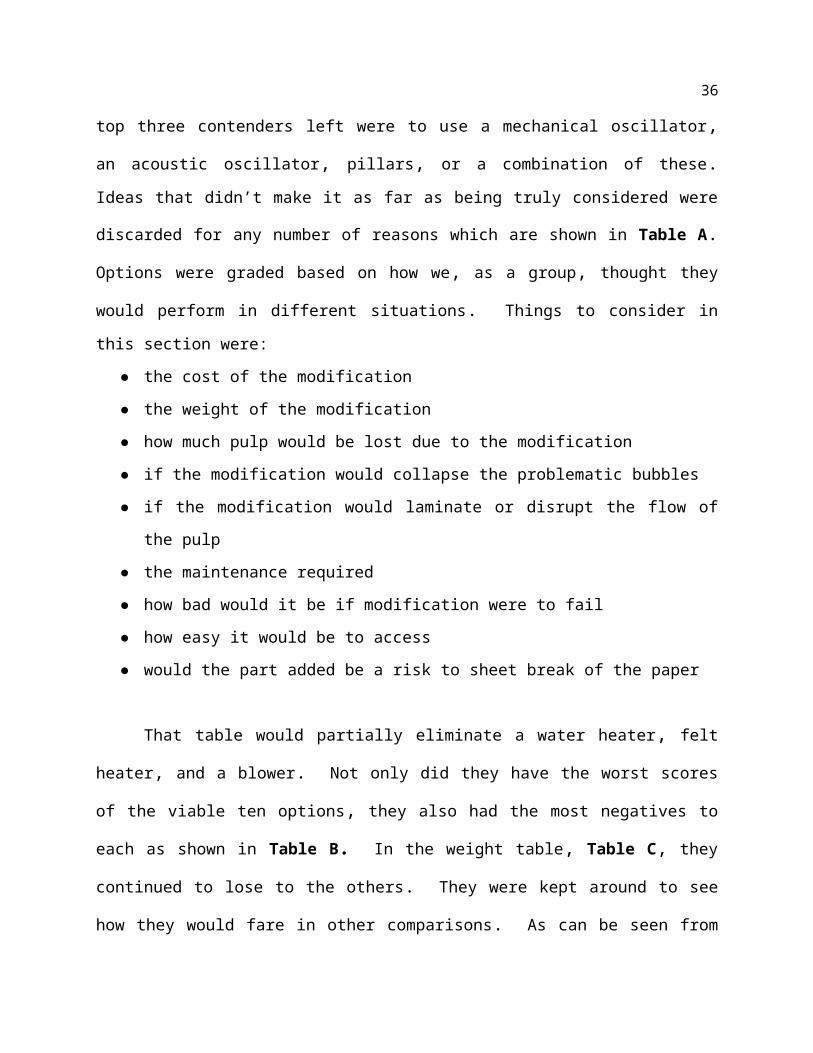
Screening moved that number to three. The top three contenders left were to use a mechanical
oscillator, an acoustic oscillator, pillars, or a combination of these. Ideas that didn’t make it as
far as being truly considered were discarded for any number of reasons which are shown in
Table A. Options were graded based on how we, as a group, thought they would perform in
different situations. Things to consider in this section were:
● the cost of the modification
● the weight of the modification
● how much pulp would be lost due to the modification
● if the modification would collapse the problematic bubbles
● if the modification would laminate or disrupt the flow of the pulp
● the maintenance required
● how bad would it be if modification were to fail
● how easy it would be to access
● would the part added be a risk to sheet break of the paper
That table would partially eliminate a water heater, felt heater, and a blower. Not only
did they have the worst scores of the viable ten options, they also had the most negatives to each
as shown in Table B. In the weight table, Table C, they continued to lose to the others. They
were kept around to see how they would fare in other comparisons. As can be seen from these
previous three tables, the best options were the acoustic oscillator, mechanical oscillator, and
pillars. Although the shield was rated in the middle of the others, it was a good enough idea that
we learned it was already in place at the San Jose plant.

26
After speaking with customers, two of three contenders were disqualified. The
mechanical oscillator and the pillars were the options that were discarded. The mechanical
oscillator was discarded because it would wear down the felt according to the paper plant.
Replacing the felt would be very costly and applying the oscillator would also be problematic .
Applying the pillars would in fact pop the bubbles that were the cause of their problems.
However, the consultants with Facility Integrations, operating within the paper mill, informed us
that on the back side of the pillars, jetties would most likely occur and lessen the quality of the
paper which is totally against our goal of increasing the machine speed. The acoustic oscillator
was the only viable option left and the group proceeded with this goal in mind to eliminate the
problems.
6.0 Concept Selection
6.1 Concept Screening
Feedback was generally received through intermediate discussion with consultants
working for Facility Integrations, the maintenance and consulting firm at which Matthew

27
Ferguson was an intern over the summer of 2014. This was done because Graphic Packaging did
not have any engineers dedicated to the wipe project anymore and could not spare the time to
discuss the parameters of the project. Facility Integrations had more interest in furthering this
specific project because helping facilitate a project with as great of a potential impact as this one
would help them to secure more projects with Graphic Packaging in the future.
Feedback was also received during the visit to the Santa Clara facility on September 11,
2015. During this visit, Jeff Mih, the production engineer.
6.2 Concept Development, Scoring, and Selection
In Table A, these creations were rated on how it was thought they would compare
against each other in different areas. The areas include:
· Cost
o How much the cost of each part will be comparatively
o Weighted at 3
· Weight
o How heavy each part will be
o Weighted at 1
· Material Loss
o How much stock will be accidently removed when removing water
o Weighted at 4
· Water Removal
o How much water will be removed
o Weighted at 4
· Laminating
o How well will the device create laminar flow
o Weighted at 4

28
· Maintenance
o How often will the device need service
o Weighted at 4
· Criticality of Failure
o How bad would it be if the item broke
o Weighted at 3
· Ease of Access
o How easy will servicing the part be
o Weighted at 2
· Risk of Sheet Break
o How often will the sheet break
o Weighted at 5
Table A and Table B use a rating system based on if it was believe the object will have
an adverse, neutral, or positive effect on the end goal. Zeros are attributed to adverse effects,
Ones are attributed to normal effects, and Twos are attributed to positive effects.
After adding the combined scores and finding an average in Table A, a baseline was determined
to decide if an object should perform well comparatively. 5 good designs, 3 bad designs, and 2
normal designs were determined from this method. On Table B, the Zeros and Twos were
counted. Comparing the numbers with averages, good and bad designs were determined. The
only design to receive a high number in both good and bad was the Shield.
Comparing these tables and values, the Indirect Water Heater, the Heated Felt, and the Blower were eliminated but used in future tables and graphs.

29
Multiplying the weighted ratings for each of the nine rating categories by the ratings that
were given to them, the values in Table C were found. Adding across the row, a Total Score
was determined and given to each design. Both of the Oscillators and the Pillars fared well
against the competition. Once again, both of the Heaters and the Blower were found to be bad
choices but kept for comparison purposes.
To increase the chances of reaching the core goal, Table D was created to show what
combinations of designs were best. The combinations were determined by what design was
thought to complement another design. The green cells represent good ideas, the yellow cells
represent neutral ideas, the red cells represent bad ideas, and the grey cells represent ideas that
we did not pair with others because either the combination does not contain laminating
properties, or they were the same concepts.
Adding the good ideas and their respective scores together, Table E shows which design
combinations were best. It also showed that all of the combination designs were all better than
even the best individual design. The green cells represent good combination ideas, the yellow
cells represent ideas that almost reached the average total score, and the blue cells represent
ideas that were worse than the average total score but better than individual total scores.
Table E – This determines how well design combinations rank against each other.

30
To further determine which of these combinations is best, a weighted combination score
and a modified weighted combination score were given to each of these setups and can be found
in Table F. The weighted combination score was determined by:
· adding both of the costs
· the highest weight
· best material loss prevention
· the best water removal score
· the best laminating properties
· the best maintenance scores
· the best criticality of failure
· the easiest to access for service
· the best prevention against sheet break score
The modified combination score was determined by:
· adding both of the costs
· adding both of the weights
· the average for the material loss prevention
· the best water removal score
· the best laminating score
· the worst maintenance score
· the worst criticality of failure
· the worst ease of access
· the worst risk of sheet break
When the calculations for the Weighted Combination Score were determined, the ranking
was congruent with how it was in Table E, However, the numbers were very close, and a winner
could not be decided. To sort out the top three candidates, a Modified Weighted Combination
Score was created. This score was also congruent with Table E. The top candidates in each

31
section are represented in green cells, the neutral in yellow cells, and the worst in red cells. To
sum up these tests, the “Pillars + Mechanical Oscillator” won the bid for being the most
promising combination of designs.
6.3 Data and Calculations for Feasibility and Effectiveness
Analysis
The feasibility of the design was first investigated by finding the exact output of the
SoundlazerTM system. Using the manufacturer-given output of 120.5 dB, the sound pressure was
found to be 21.185Pa. The wavelength of the sound traveling through the air above the machine,
considering the 300K ambient temperature and the 100% air humidity is 0.8835 cm or 0.3478 in.
The sound velocity under these conditions was then found to be 353.42 m/s. The pressure
created by the weight of the stock was found and used as a reference metric. This value was
found to be 30.51Pa, showing that the force of the SoundlazerTM was quite significant in this
setting. The surface tension required for a 1/16” diameter bubble to stay together under this
added pressure was found to be 0.0168N, which is quite significant for a bubble. The actual
outward pressure of a bubble of this size was found to be 0.000801N, so a bubble of this size
would certainly collapse under the added pressure.

32
7.0 Final design
Figure 3 - Final Design with SoundlazerTM Mount
Figure 4 - Mill Support Bracket

33
7.1 Capabilities and Functionality
This device is capable of rupturing bubbles of radii of 1/32”, and potentially smaller, on
the surface of paper pulp traveling on a felt traveling at speeds below 740 feet per minute. Due to
the high frequency oscillation, it is also capable of drawing bubbles trapped within the solution
to the surface, combining them into larger bubbles, and then popping these larger bubbles once
they have reached a large enough size. According to our estimations, this will allow the machine
to be ran at 715 feet per minute without encountering the slinging issues seen before.
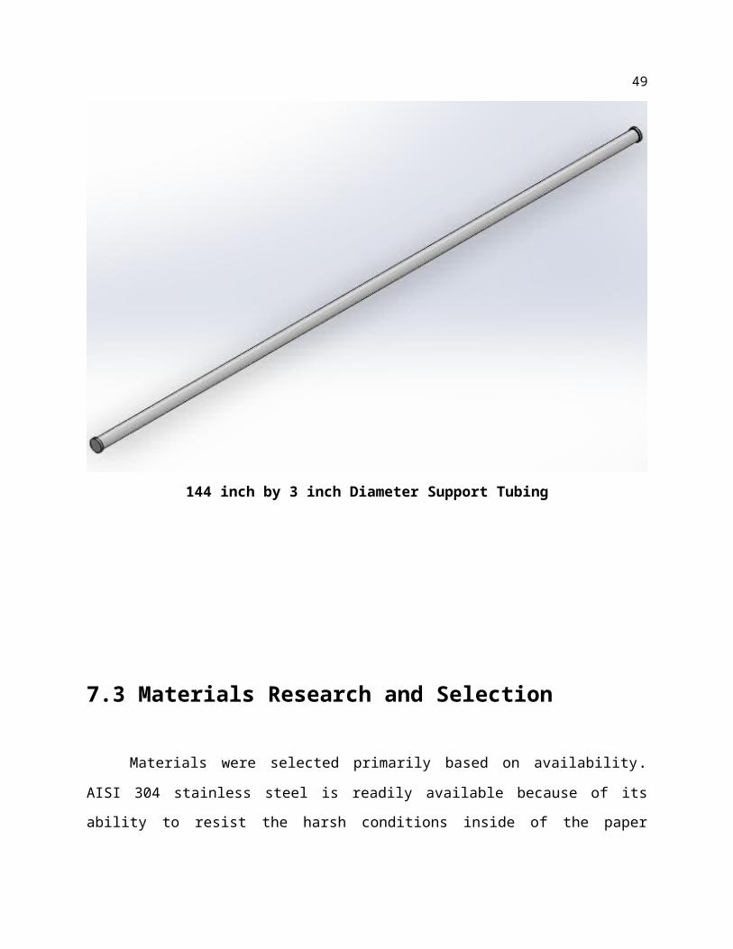
7.2 Design RevisionsThe initial design consisted on a 144 inch x 2 inch diameter AISI 304 SS tube with a wall
thickness of 0.25 inches. This was found to perform well in all the simulations, except when it
came to the displacement created in the static simulation. The displacement was found to be
around 0.3 inches across the center of the 144 inch span of the tubing. To counter this, a new
diameter of 3 inches and a wall thickness of 0.25 inches was used. This brought the displacement
across the span down from 0.3 inches to around 0.1 inches. Additionally, the Factor of Safety
increased from a value of 3.62 to a new value of 4.8. Although this is double the minimum of a
Factor of Safety of 2.0, it is assumed that this member will be under the greatest stresses overall.

34
144 inch by 3 inch Diameter Support Tubing
7.3 Materials Research and Selection
Materials were selected primarily based on availability. AISI 304 stainless steel is readily
available because of its ability to resist the harsh conditions inside of the paper machine at a
reasonable cost. The heat and humidity inside of the machine create corrosive conditions on their
own, but the felt is also occasionally washed with a pervasive acid in order to remove caked on

35
stock. This acid is detrimental to many metals, but the 304 stainless steel can resist it. Thus, the
framing for the machine will be composed of this variety of stainless.
To reduce the impact of the SoundlazerTM vibration, damping steel is used to separate the
emitters from the stainless frame.
7.4 Manufacturing, Assembly, and CostThe cost of manufacturing will be kept at a minimum by having all of the assembly and
machining work done by the millwrights at any facility that requires this design. The average pay
rate for an experienced millwright is $35/hour, which is far cheaper than what it would cost to
have the machining and assembly done off site. The hollow tubing for the support rod would be
ordered as is and cut to length if necessary. All surface finishing, which would receive a high
polish finish to avoid unnecessary moisture and acid penetration. The framework would be
manufactured from AISI 304N stainless steel stock of the proper thickness, and would be shaped
in-house using a pneumatic vice. The emitter systems would then be bolted to the assembly, the
wires would be fed through the hollow tube, and the amplifiers would be attached at the ends and
bolted to the machine frame. The total manufacturing time would be at most 3 hours with 2
millwrights and 1 hour with 3 millwrights.
7.5 Cost Analysis
The overall design will consist of 26 emitter system and the 13 acoustic generator devices
for the system. The pricing of these are $200 and $300 respectively. In the end, total cost for
36
these specific entities come to a total of $9100. With the cost of cost of labor priced at $35 for 6
hours in total manufacturing and installation with 2 people, and the material cost of the around
$2450 in total, at $7000 per ton, the total cost of the entire construction would be $11,865. To
match the number of wipes and construct 3 of these units, it would cost $35,595. This is $4,405
under estimated $40,000 price line set by the customer.
7.4 Design Drawings, Parts List, and Bill of Materials
Full Assembly
Item Units Unit Cost Total Cost
Emitters 26 $200 $5200
Generators 13 $300 $3900
Labor 9 $35/hr $315
Steel 712 pounds $7000/ton $2450

37
Total Cost: $11,865/unit, $35,595 for 3 units to match the number of wipes
7.5 Design Validation
Through the use of the prototype, we found very important non-quantified information.
The prototype showed that it was possible to pop bubbles using sound, and therefore prove the
basics of our concept.Solidworks simulations were then used to find many of the critical values for the design
validation, namely the factor of safety. This ensured that the design would maintain its strength
and be able to perform its required function for a long period of time.
Calculations supporting the exact output values needed can be found in the appendix.
These values include the pressure output of the sonic system, the pressure on the bubbles, the
pressure which each bubble can withstand, and the pressure created by the weight of the stock
itself.
7.6 Finite Element Analysis/Simulation
Figure 1 and 2 below shows our test for the plain static load of the weight of our design
frame. This is a very critical simulation as we had such limited space and so few mounting points
to support a very heavy object. Our design turned out very sturdy and with a factor of safety of
3.67 we know it will hold very firm. There is room to lighten our device as we have plenty of
room in the factor of safety, however, we have decided to keep the machine as designed because
of the environment and the interests of the customer. In the highly corrosive environment it will
be in will corrode the device no matter how well we design it, so we want to ensure no matter
how aggressive the environment becomes it will hold firm unless something very drastic

38
happens. On top of that the mill will be very reluctant to pay the money we will need to ask if
they cannot be sure it will last long enough to pay for itself.
Static Stress Simulation Fig 1.

39
Static Strain Simulation Fig 2.Figure 3 is our displacement simulation from the static loading on our device so we can
see how much it will move from the plain static load. This turned out to be minimal thankfully as
the more movement we have the more variation of power the stock will feel. Our movement
from the static load is a mere two tenths of an inch, allowing us to set a fairly precise spacing for
our device. With this knowledge and our understanding of the wave produced by the
SoundlazerTM device we were able to place it in the ideal height and know that it will stay in the
right power range for the oscillator.

40
Static Displacement Simulation Fig 3.
Below are several figures showing the strains at various frequency loading. This is very
necessary in our project as we will be producing a fair bit of vibration using sound at the power
we will be using. There was a chance that the frequencies our calculations said would be most
effective would also cause some resonance in our product or worse the machine itself. We
discovered two hundred and eighty hertz and eleven thousand hertz should be the most effective
for bubble popping at different consistencies. We want our device to provide the option to pick
what frequency so the mill can increase effectiveness no matter the conditions of the day. At the
lower frequency you have a little more push for days where the stock is a little more viscous so
the fibers are less likely to be effected. At the higher frequencies the fibers will be less effective
and with the lower viscosity the bubbles will more readily pop from the rapid cycling.

41
Dynamic Stress @ Frequency ~ 40 kHz Fig 4.
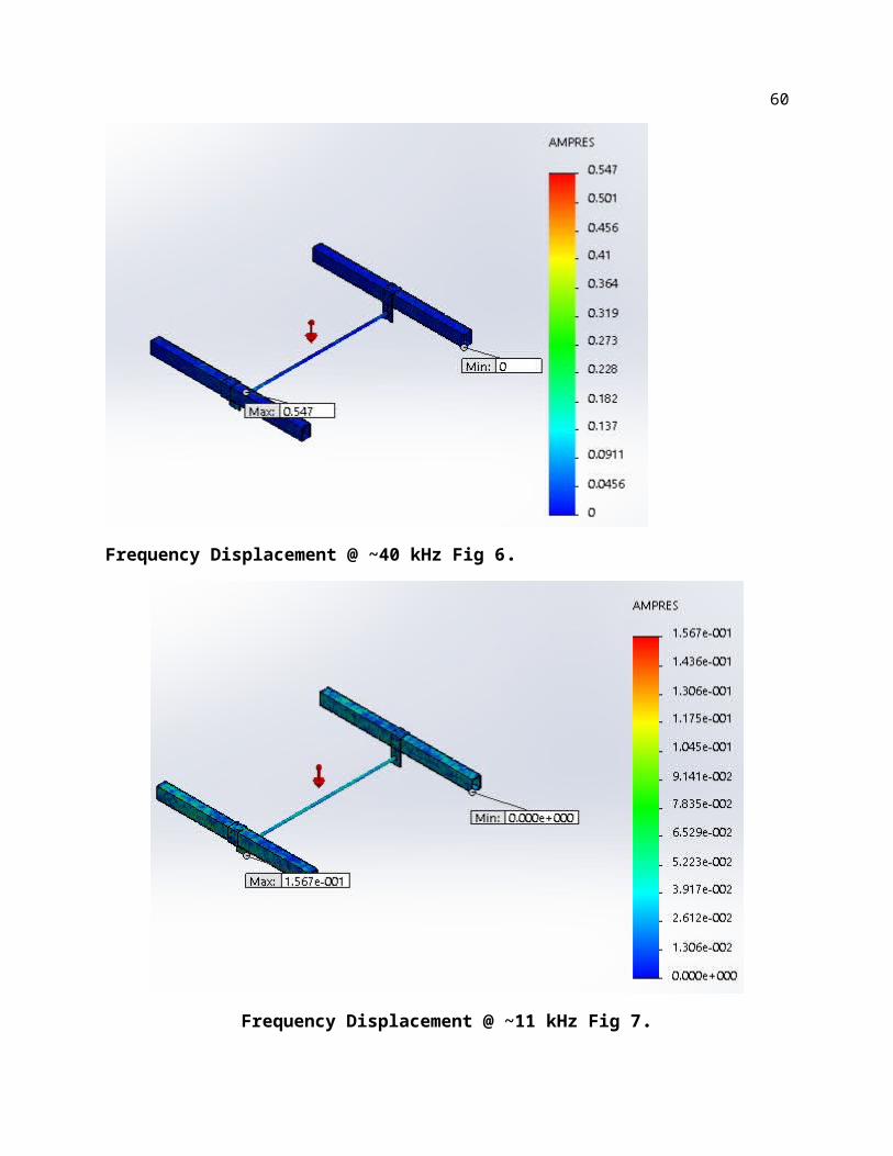
Figure 5, 6, and 7 below show displacement from the frequency loading on our support. This was a primary concern with the possibility of this vibration reaching resonance with our
support, and the frame of the machine. If we had any kind of resonance it could cause serious
repercussions on the longevity of the machine as well as our design. Reaching resonance on our
support for the sound emitters could cause an increasing vibration that eventually warps, breaks,
or loosens our bar support, this can lead to jamming up the mechanics or have pieces fall into the
stock. However, if we had resonance with the frame there are much more severe consequences
like irreparably damaging the well over one hundred million dollar machine from excessive
fatigue by our small device. The results of the simulation give a great factor of safety, enough
that we could comfortably even increase power without fear of affecting the overall design.
Though this is not the limiting force on our model it still enforces the solidity of our design.

42
Dynamic Displacement Simulation @ ~40 kHz Fig 5.
Frequency Displacement @ ~40 kHz Fig 6.

43
Frequency Displacement @ ~11 kHz Fig 7.

44
7.7 Prototype Test
The goal behind creating the prototype was to prove the concept of popping bubbles using
sound. The prototype was made using a food processing conveyor belt, metal stock, and two
computer speakers. The conveyor belt was loaned to us by Brian Garland, owner of Garland
Venture Group. The metal stock and speakers were purchased by us. Soap bubbles are used to
represent the bubbles that will be in the stock. These are not the same type of bubbles, but the
prototype focuses on proving the concept of collapsing bubbles using sound. The bubbles can be
seen vibrating and collapsing during operation.
Paper stock with the proper amount of dissolved bubbles would have been extremely
difficult to simulate and we could not recreate the bubble that would be found at the paper mill. We decided to use a simulant that would be significantly harder to pop to show if we can pop
those, we can definitely pop the stock bubbles. We used soap bubbles on cardboard to simulate
the bubbles in the stock running on the felt, this allowed us to vary the speed without fear of
throwing stock off the belt, or having too much fluid seep through our conveyor belt while still
having the absorbent trait of the felt below the stock. However, we also decided on soap bubbles
because they were much harder to pop than the bubbles in the stock that is mostly water. This
was known, as soap forms significantly stronger bonds to itself than water and has a higher
surface tension, therefore, the bubble created in it will be more difficult to pop. Our tests on the
soap bubbles succeeded in showing the ability of sound waves to pop bubbles not in contact with
the emitter itself. We also confirmed our beliefs about soap bubbles as opposed to stock bubbles
as we watched the bubbles flex and warp in shape rather than pop on occasion. We know from
the wipe design we are replacing that on pressure being applied to the bubbles in the stock they

45
will pop rather than deform and stay solid. As such we feel popping soap bubbles is more than
enough evidence that it will pop stock bubbles.
As for the test we discovered that lower frequency seemed to be more effective for
moving the bubbles around where high frequency tended to visually move it less but did not have
a drastic effect on how many or how fast the bubbles were ruptured. However, we also know that
may be from hitting the acoustic saturation of the speakers we were using. This is not too big of
a concern as we want the official design to have a wide variance of frequency for other design
needs and the most effective frequency can be dialed in for that mill and that particular product. We were able to show that the bubbles are popping immediately upon facing the pressure from
the sound waves, this confirms our belief that the speed should not matter to our device and as
the bubble is impacted by the sound wave it will pop immediately allowing our product to be
continually used if another speed up is needed.

46
Prototype 1

47
Prototype 2

48
Prototype 3
49
Prototype 4

50
8.0 Conclusions
Our project was an interesting combination of acoustic theory and mechanical design
with stress and strain from both weight and the movement caused by the oscillating speakers
producing sound waves. The SoundlazerTM system produces plenty of pressure to pop bubbles
on the paper stock especially with the shock factor on the bubbles moving under the emitters
from a previously relaxed state. Our prototype was a key factor in proving that the theory is
sound. We discovered it was very difficult to simulate the paper stock itself without the
proprietary chemicals used at the mill and, therefore, had to use stand in bubbles that would be
much harder to pop to prove the validity of our prototype. We used soap bubbles on cardboard to
simulate the mostly liquid stock stuck to the absorbent felt, we felt this would be a great test of
the idea and prove our theory of the device. We know that the power from the actual speaker will
far exceed our prototype speakers and could be cranked up if we miscalculated the surface
tension of the stock and needed to brute force a little bit. We discovered just how tough the soap
bubbles really were, assuring them as a viable simulation of the stock bubbles.
The simulations and calculations we have done point to our design working well and
effectively far below the maximum ability. This means we can up power, pressure, and overall
effectiveness of our device if it needs to, or we can run it at a lower state to save power and
stress on our system, with less vibration acting on the welds and mounts. We have calculated the
approximate surface tension of the bubbles we will be facing and the amount of tension needed
for the bubbles to stay together. We also know the pressure our system puts out and based on the
bubbles size we are trying to pop we know the pressure needed to pop them. The amount of
pressure being applied is far in excess of what is needed for the design to work. As we cannot
due a large scale test due to cost restrictions and time restrictions we had to confirm with
prototyping, calculation, and simulation that our design should work. As with all conceptual

51
designs the validation of the theory is the key to moving forward and the only part left in our
design is to test it on the machine to see how effective it really is.
Acknowledgement
Jose Saez, Mill Manager, GPI Santa Clara
Jeff Mih, Production Supervisor, GPI Santa Clara
Terry Barker, Quality Supervisor, GPI Santa Clara
Joel Sanchez, Maintenance Forman, GPI Santa Clara
Brian Garland, Owner, Garland Venture Group, for supplying us with the conveyor
Dr. Mir Atiqullah, Advisor, KSU ME Department

52
References
D. Krefting, R. Mettin, W. Lauterborn, “High-speed observation of acoustic cavitation
erosion in multibubble systems”, Drittes Physikalisches Institut, Universitat Gottingen,
Burgerstr. 42-44, 37073 Gottingen, Germany
Mikko O. Lamminen, Harold W. Walker, Linda K. Weavers, “Mechanisms and factors
influencing the ultrasonic cleaning of particle-fouled ceramic membranes”, Department
of Civil and Environmental Engineering and Geodetic Science, The Ohio State
University,
2070 Neil Avenue, Columbus, OH 43210, USA. Received 14 March 2003; received in revised
form 16 February 2004; accepted 24 February 2004
Bogdan Niemczewski, “Observations of water cavitation intensity under practical ultrasonic
cleaning conditions”, Tele- and Radio Research Institute, ul. Ratuszowa 11, 03-450
Warsaw, Poland. Received 8 November 2004; accepted 18 November 2005
Available online 7 February 2006
"Occupational Noise Exposure. - 1910.95." Occupational Noise Exposure. - 1910.95.
N.p., n.d. Web. 01 Dec. 2015.
PPE:"General Requirements. - 1910.132." General Requirements. - 1910.132. N.p., n.d. Web.
01 Dec. 2015.

53
Cleaning and Working: "General Requirements. - 1910.22." General Requirements. - 1910.22.
N.p., n.d. Web. 01 Dec. 2015.
U.S. Patent US4205966 A, http://www.google.com/patents/US4205966
U.S. Patent US4398925 A, http://www.google.com/patents/US4398925
http://sonomechanics.com/applications/liquid_degassing/
http://sonomechanics.com/products_services/3000_w_industrial-scale_processor/

54
AppendicesAppendix A: Wet End Drawing

55
Table A Table B

56
6.2 Table C
6.2 Table D

57
6.2 Table E
Ultrasonic degasser

58
Santa Clara Kobayashi Machine
Wet end complete drawing

59
Forming Roll earlier in the system (no slinging)
Forming roll later in the system (slinging)
60
Hand-held demonstration wipe in place
Effect of hand-held wipe

61
Final Product
Opportunity for GPI Santa Clara facility

62
Feasibility Calculations Page 1

63
Feasibility Calculations Page 2