Embed Size (px)
Citation preview

Seminar ‘Bridge Design with Eurocodes’ – JRC Ispra, 1-2 October 2012 1
EU-Russia Regulatory Dialogue: Construction Sector SubgroupEU-Russia Regulatory Dialogue: Construction Sector Subgroup
Seminar ‘ Bridge Design with Eurocodes’JRC-Ispra, 1-2 October 2012
O i d d t d bOrganized and supported byEuropean Commission
DG Joint Research CentreDG Enterprise and Industry
Russian FederationFederal Highway Agency, Ministry of Transport
European Committee for StandardizationEuropean Committee for StandardizationTC250 Structural Eurocodes

Seminar ‘Bridge Design with Eurocodes’ – JRC Ispra, 1-2 October 2012 2
Actions (loading) on bridges
N. MalakatasChairman of CEN/TC250/SC1
Director for Design & Studies of Road WorksGreek Ministry DCITN
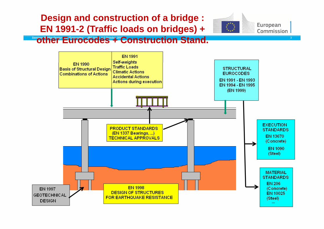
Design and construction of a bridge : EN 1991-2 (Traffic loads on bridges) +
h E d C i S dSeminar ‘Bridge Design with Eurocodes’ – JRC Ispra, 1-2 October 2012 3other Eurocodes + Construction Stand.
ACTIONS ON A BRIDGESeminar ‘Bridge Design with Eurocodes’ – JRC Ispra, 1-2 October 2012 4
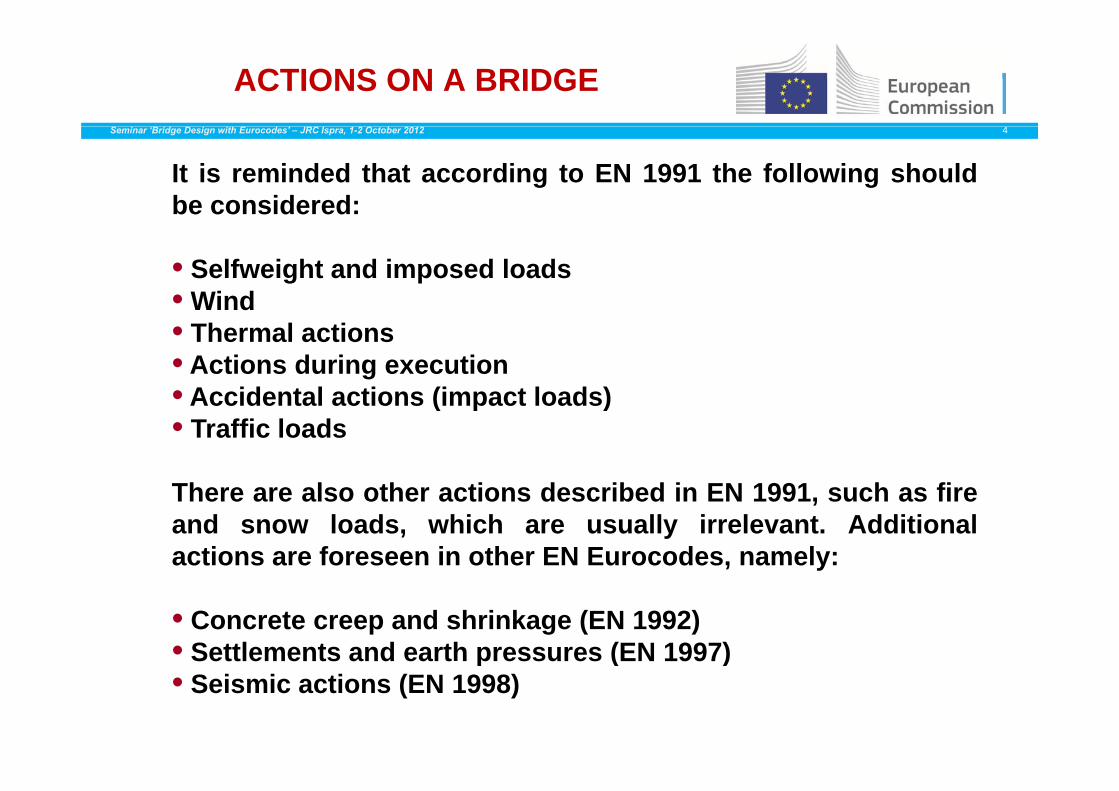
It is reminded that according to EN 1991 the following shouldbe considered:
• Selfweight and imposed loads• WindWind• Thermal actions• Actions during execution• Accidental actions (impact loads)• Accidental actions (impact loads)• Traffic loads
Th l th ti d ib d i EN 1991 h fiThere are also other actions described in EN 1991, such as fireand snow loads, which are usually irrelevant. Additionalactions are foreseen in other EN Eurocodes, namely:
• Concrete creep and shrinkage (EN 1992)• Settlements and earth pressures (EN 1997)p ( )• Seismic actions (EN 1998)

PARTS AND IMPLEMENTATION OF EN 1991
Seminar ‘Bridge Design with Eurocodes’ – JRC Ispra, 1-2 October 2012 5
Part of Eurocode 1 : Actions on structures Title (Subject) Issued
EN 1991-1-1 General actions – Densities, self-weight, imposed loads for buildings
April 2002
EN 1991-1-2 General actions – Actions on structures November 2002exposed to fire
EN 1991-1-3 General actions – Snow loads July 2003
EN 1991 1 4 G l ti Wi d ti A il 2005EN 1991-1-4 General actions – Wind actions April 2005
EN 1991-1-5 General actions – Thermal actions November 2003
EN 1991-1-6 General actions – Actions during execution
June 2005
EN 1991-1-7 General actions – Accidental actions July 2006
EN 1991-2 Traffic loads on bridges September 2003
EN 1991-3 Actions induced by cranes and hi
July 2006machinery
EN 1991-4 Silos and tanks May 2006

ACTIONS : SELFWEIGHTSeminar ‘Bridge Design with Eurocodes’ – JRC Ispra, 1-2 October 2012 6
Safety barrierSafety barrier
Concrete support for the safety barrier
8 cm thick asphat layer8 cm thick asphat layer
Cornice
3 cm thick waterproofing layer
ACTIONS : SELFWEIGHTSeminar ‘Bridge Design with Eurocodes’ – JRC Ispra, 1-2 October 2012 7
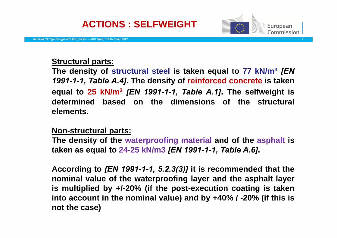
Structural parts:pThe density of structural steel is taken equal to 77 kN/m3 [EN1991-1-1, Table A.4]. The density of reinforced concrete is takenequal to 25 kN/m3 [EN 1991-1-1 Table A 1] The selfweight isequal to 25 kN/m3 [EN 1991-1-1, Table A.1]. The selfweight isdetermined based on the dimensions of the structuralelements.
Non-structural parts:The density of the waterproofing material and of the asphalt istaken as equal to 24-25 kN/m3 [EN 1991-1-1, Table A.6].
According to [EN 1991-1-1, 5.2.3(3)] it is recommended that theg [ ( )]nominal value of the waterproofing layer and the asphalt layeris multiplied by +/-20% (if the post-execution coating is takeninto account in the nominal value) and by +40% / -20% (if this isinto account in the nominal value) and by 40% / 20% (if this isnot the case)
EN 1991-2: TRAFFIC LOADS ON BRIDGES
Seminar ‘Bridge Design with Eurocodes’ – JRC Ispra, 1-2 October 2012 8
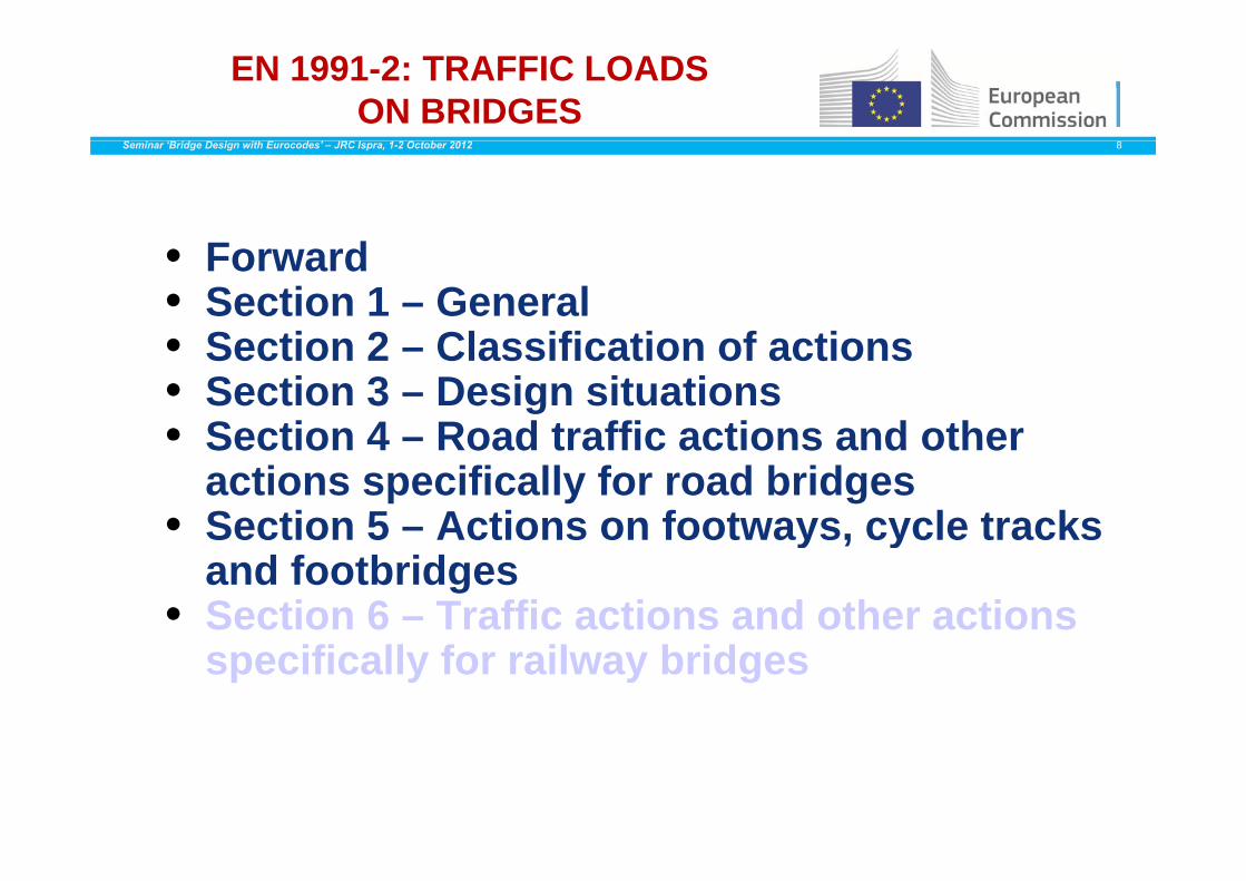
• Forward• Section 1 – General• Section 2 Classification of actions• Section 2 – Classification of actions• Section 3 – Design situations• Section 4 – Road traffic actions and otherSection 4 – Road traffic actions and other
actions specifically for road bridges• Section 5 – Actions on footways, cycle tracks y , y
and footbridges• Section 6 – Traffic actions and other actions
specifically for railway bridges

EN 1991-2: TRAFFIC LOADS ON BRIDGES
Seminar ‘Bridge Design with Eurocodes’ – JRC Ispra, 1-2 October 2012 9
• Annex A (informative) – Models of special vehicles for road bridgesroad bridges
• Annex B (informative) – Fatigue life assessment for road bridges assessment method based on recorded traffic
• Annex C (normative) Dynamic factors 1 + φ for real• Annex C (normative) – Dynamic factors 1 + φ for real trains
• Annex D (normative) – Basis for the fatigue assessment of il t trailway structures
• Annex E (informative) – Limits of validity of load model HSLM and the selection of the critical universal train from HSLM-A
• Annex F (informative) – Criteria to be satisfied if a dynamic analysis is not requiredy y q
• Annex G (informative) – Method for determining the combined response of a structure and track to variable actionsactions
• Annex F (informative) – Load models for rail traffic loads in transient design situations
EN 1991-2: TRAFFIC LOADS ON BRIDGES
Seminar ‘Bridge Design with Eurocodes’ – JRC Ispra, 1-2 October 2012 10
0.05
0.06
0.07
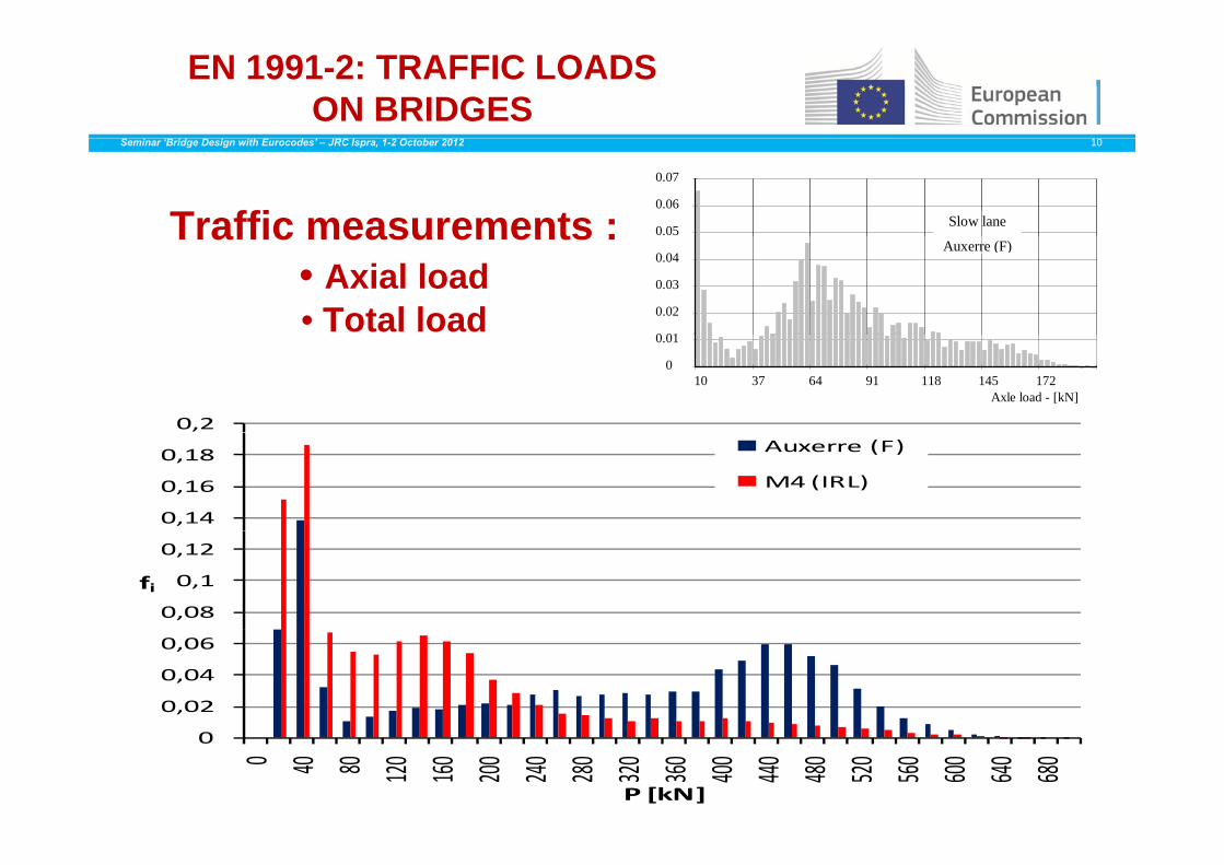
Slow laneTraffic measurements :
0 01
0.02
0.03
0.04Auxerre (F)
Traffic measurements :• Axial load• Total load
0
0.01
10 37 64 91 118 145 172Axle load - [kN]
0,2
0,14
0,16
0,18 Auxerre (F)
M4 (IRL)
0,08
0,1
0,12
fi
0,02
0,04
0,06
0
0 40 80 120 160 200 240 280 320 360 400 440 480 520 560 600 640 680
P [kN]
EN 1991-2: TRAFFIC LOADS ON BRIDGES
Seminar ‘Bridge Design with Eurocodes’ – JRC Ispra, 1-2 October 2012 11
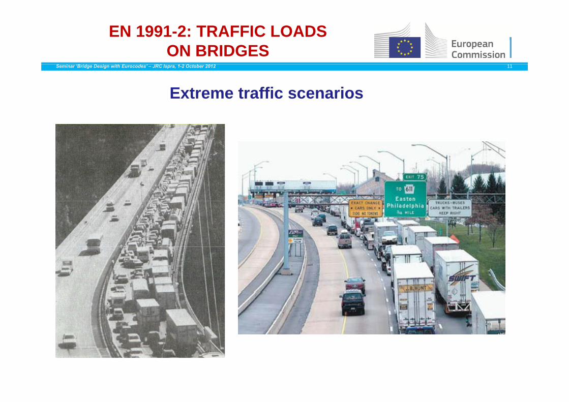
Extreme traffic scenarios

ACTIONS : TRAFFIC LOADS -General organisation for road bridges
Seminar ‘Bridge Design with Eurocodes’ – JRC Ispra, 1-2 October 2012 12
Traffic load models
- Vertical forces : LM1, LM2, LM3, LM4- Horizontal forces : braking and acceleration,Horizontal forces : braking and acceleration,
centrifugal, transverse
Groups of loads
1 1b 2 3 4 5- gr1a, gr1b, gr2, gr3, gr4, gr5- characteristic, frequent and quasi-permanent
valuesvalues
Combination with actions other than traffricCombination with actions other than traffricactions
Load Models (Vertical) for Road BridgesSeminar ‘Bridge Design with Eurocodes’ – JRC Ispra, 1-2 October 2012 13
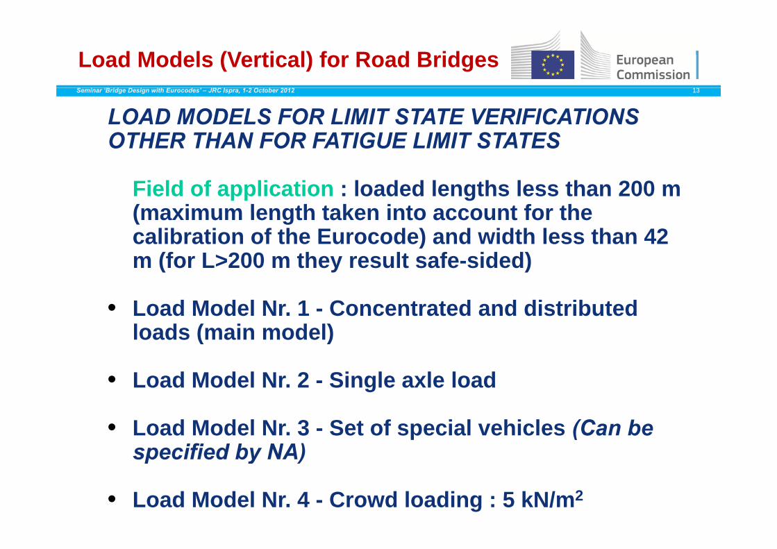
LOAD MODELS FOR LIMIT STATE VERIFICATIONS OTHER THAN FOR FATIGUE LIMIT STATES
Field of application : loaded lengths less than 200 m (maximum length taken into account for the(maximum length taken into account for the calibration of the Eurocode) and width less than 42 m (for L>200 m they result safe-sided)
• Load Model Nr. 1 - Concentrated and distributed loads (main model)loads (main model)
• Load Model Nr. 2 - Single axle load
• Load Model Nr. 3 - Set of special vehicles (Can be specified by NA)p y )
• Load Model Nr. 4 - Crowd loading : 5 kN/m2
Carriageway width wSeminar ‘Bridge Design with Eurocodes’ – JRC Ispra, 1-2 October 2012 14
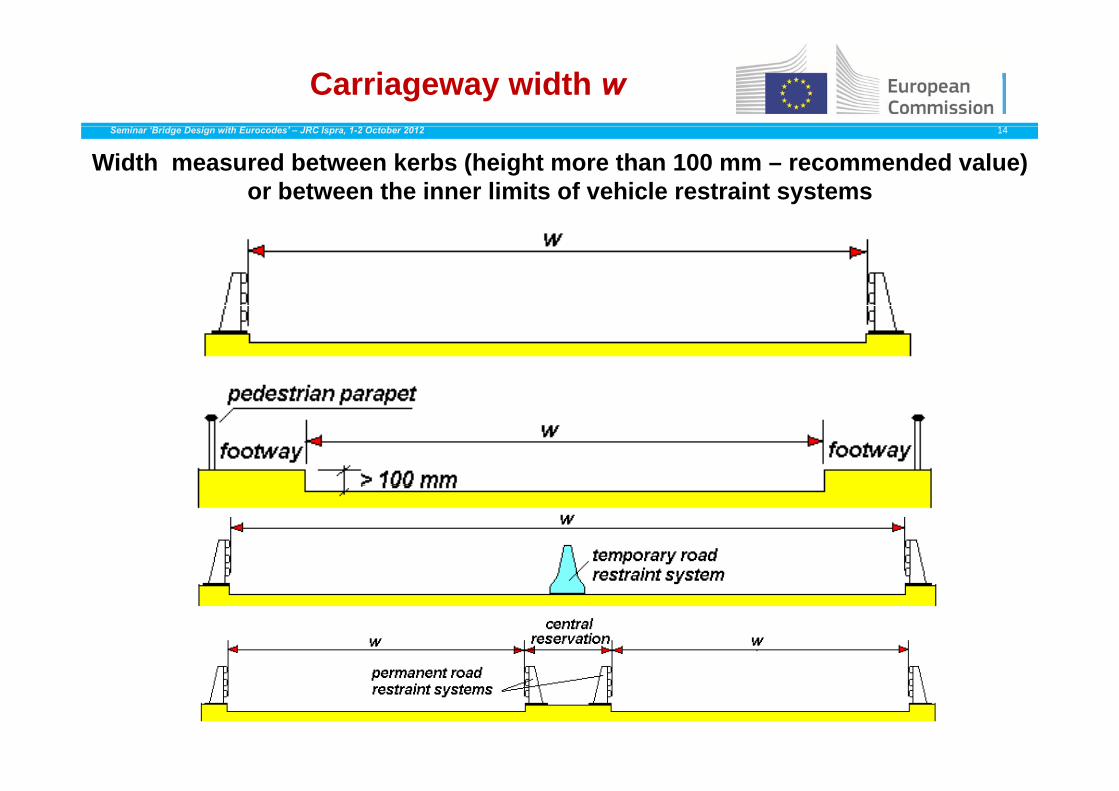
Width measured between kerbs (height more than 100 mm – recommended value) or between the inner limits of vehicle restraint systems

Division of the carriageway into notional lanes
Seminar ‘Bridge Design with Eurocodes’ – JRC Ispra, 1-2 October 2012 15Carriagewaywidth
Number of notional lanes
Notional lane width Width of the remaining area
w < 5,4 m = 1 3 m w – 3 m
5,4 m w < 6 m = 2 02/w
n
n5,4 m w 6 m 2 0
6 m w 3 m w - 3 3/int wn
2/w
n
Remaining area
1 – Lane n° 1 (3m)
2 Lane n° 2 (3m)
Notional lane n. 1
Remaining area
Notional lane n 2
3.0
3 0 2 – Lane n 2 (3m)
3 – Lane n° 3 (3m)Remaining area
Notional lane n. 2
Notional lane n 33 0
3.0w
4 – Remaining areaRemaining area
Notional lane n. 33.0

The main load model (LM1)Seminar ‘Bridge Design with Eurocodes’ – JRC Ispra, 1-2 October 2012 16
qrk = 2,5 kN/mqrk = 2,5 kN/m22
q1k = 9 q1k = 9 kN/kN/ 22kN/mkN/m22
q2k = 2 5 kN/mq2k = 2 5 kN/m22q2k = 2,5 kN/mq2k = 2,5 kN/m22
q3k = 2,5 kN/mq3k = 2,5 kN/m22
qrk = 2,5 kN/mqrk = 2,5 kN/m22
TS T d tq ,q ,
TS : Tandem systemUDL : Uniformly distributed load
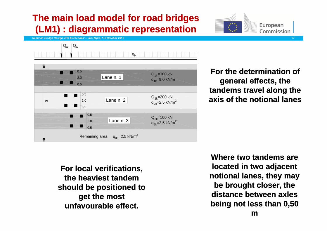
The main The main loadload model for road bridges model for road bridges (LM1) : (LM1) : diagrammaticdiagrammatic representationrepresentation
Seminar ‘Bridge Design with Eurocodes’ – JRC Ispra, 1-2 October 2012 17
QikQik
qik
For the For the determinationdetermination of of generalgeneral effectseffects, the , the
tandemstandems traveltravel alongalong thethe
Lane n. 1Q =300 kNq =9.0 kN/m
1k
1k
0.5
2.0
0.5
tandems tandems traveltravel alongalong the the axis of the axis of the notionalnotional laneslanesLane n. 2
0.5
2.0
0.5
Q =200 kN2kq =2.5 kN/m2k
2
0.5
w
Lane n. 3Q =100 kN3kq =2.5 kN/m3k
2
Remaining area q =2.5 kN/mrk2
0.5
2.0
0.5
For localFor local verificationsverificationsWhereWhere twotwo tandems are tandems are locatedlocated inin twotwo adjacentadjacentFor local For local verificationsverifications, ,
the the heaviestheaviest tandem tandem shouldshould bebe positionedpositioned to to
tt thth tt
locatedlocated in in twotwo adjacent adjacent notionalnotional laneslanes, , theythey maymay
bebe broughtbrought closercloser, the , the distancedistance betweenbetween axlesaxlesgetget the the mostmost
unfavourableunfavourable effecteffect..distance distance betweenbetween axlesaxlesbeingbeing not not lessless thanthan 0,50 0,50
m m

Subdivision of a composite bridge in notional lanes (example)
Seminar ‘Bridge Design with Eurocodes’ – JRC Ispra, 1-2 October 2012 18
12 00 2 00
Modelled girder
1 00
Modelled girder
0,50
2,00 2,00
3,00 3,00 3,001,00
Lane 1 Lane 2 Lane 33,50 3,50
Girder no. 1 Girder no. 2
Axl
e of
the
brid
ge
Girder no. 1 Girder no. 2
he b
ridge
Physical lanes
3,50 3,50
Axl
e of
th
Notional lanes
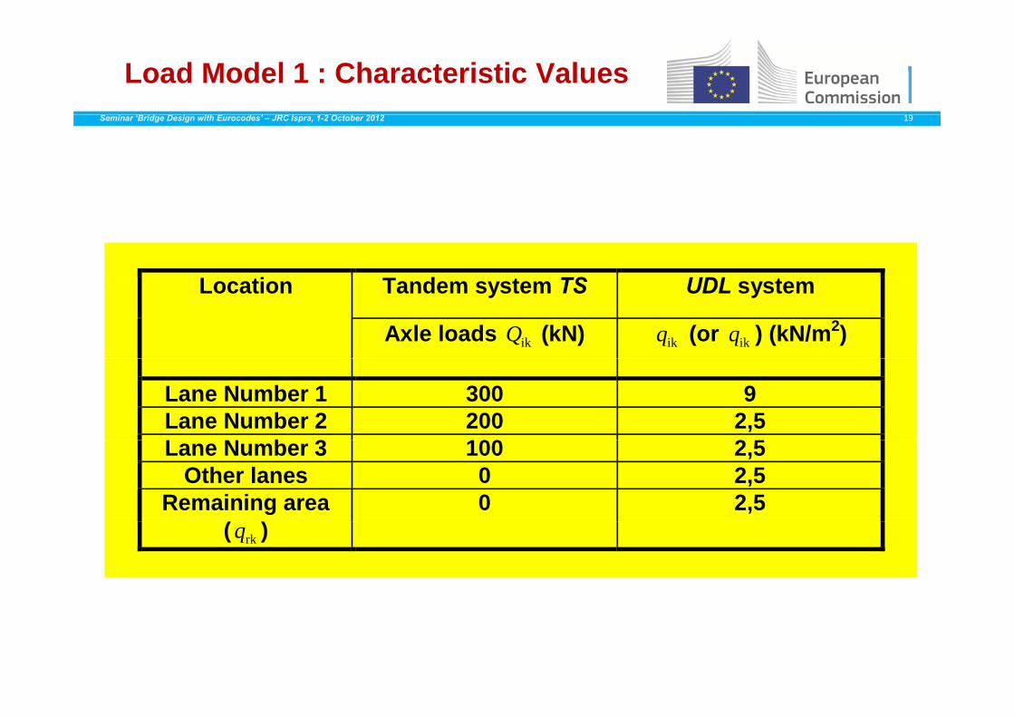
Load Model 1 : Characteristic ValuesSeminar ‘Bridge Design with Eurocodes’ – JRC Ispra, 1-2 October 2012 19
i T d TS UDLLocation Tandem system TS UDL system
Axle loads ikQ (kN) ikq (or ikq ) (kN/m2)
Lane Number 1 300 9 Lane Number 2 200 2,5 L N b 3 100 2 5Lane Number 3 100 2,5
Other lanes 0 2,5 Remaining area 0 2,5
( rkq )
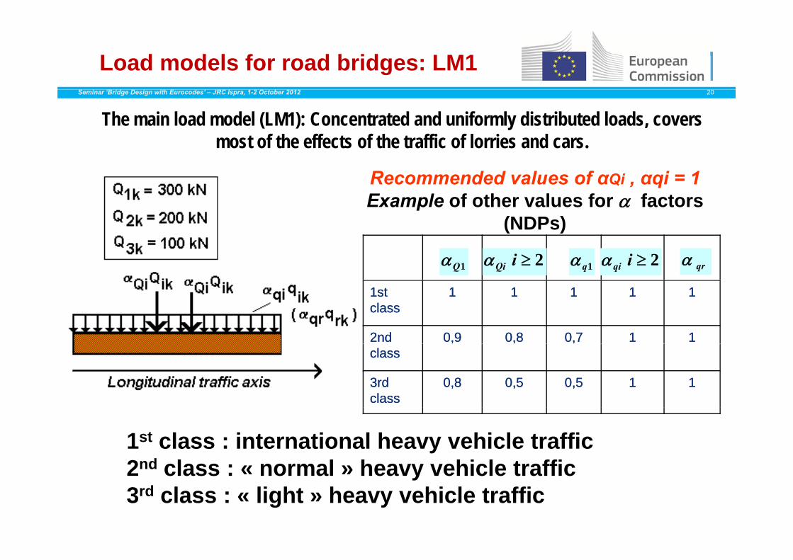
Load models for road bridges: LM1Seminar ‘Bridge Design with Eurocodes’ – JRC Ispra, 1-2 October 2012 20
The main load model (LM1): Concentrated and uniformly distributed loads, covers most of the effects of the traffic of lorries and cars.
Recommended values of αQi , αqi = 1Example of other values for factors
(NDP )
1Q 2iQi 1q 2iqi qr
(NDPs)
1st 1st classclass
11 11 11 11 11
2nd 2nd 0,90,9 0,80,8 0,70,7 11 11classclass
3rd 3rd classclass
0,80,8 0,50,5 0,50,5 11 11
1st class : international heavy vehicle traffic2nd class : « normal » heavy vehicle traffic2 class : « normal » heavy vehicle traffic3rd class : « light » heavy vehicle traffic
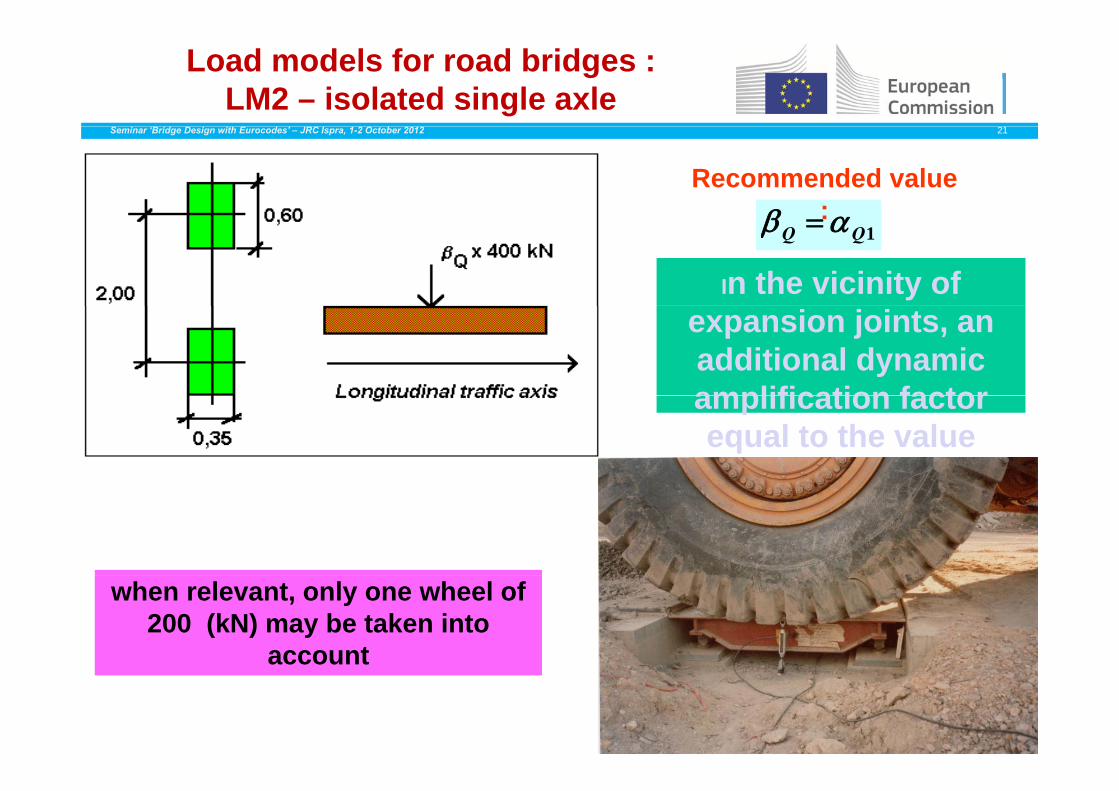
Load models for road bridges : LM2 – isolated single axle
Seminar ‘Bridge Design with Eurocodes’ – JRC Ispra, 1-2 October 2012 21
Recommended value
:1QQ :
In the vicinity of expansion joints, an additional dynamic amplification factoramplification factor equal to the value defined in 4.6.1(6) de ed 6 (6)should be applied.
when relevant, only one wheel of 200 (kN) may be taken into
account
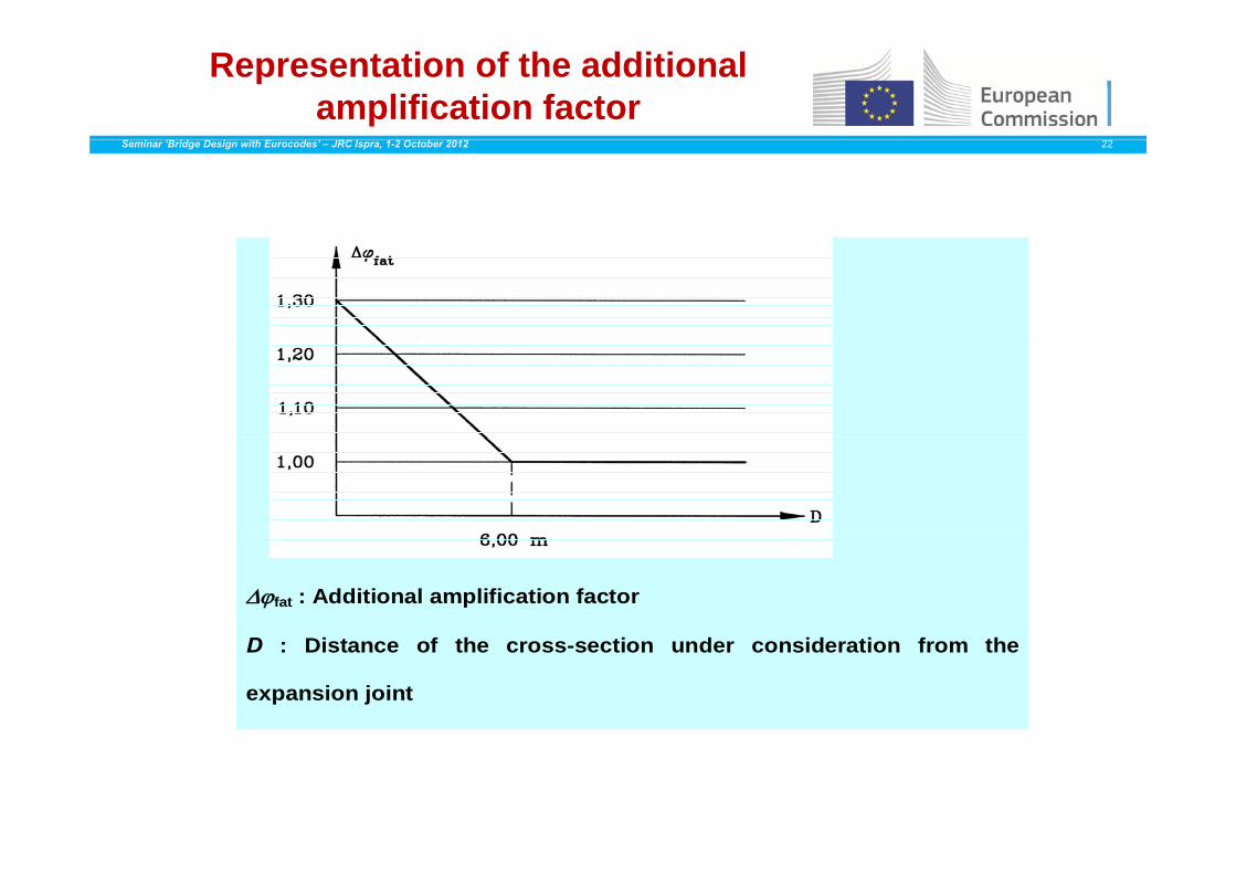
Representation of the additional amplification factor
Seminar ‘Bridge Design with Eurocodes’ – JRC Ispra, 1-2 October 2012 22
fat : Additional amplification factor
D : Distance of the cross-section under consideration from the
expansion joint
Load models for road bridgesSeminar ‘Bridge Design with Eurocodes’ – JRC Ispra, 1-2 October 2012 23
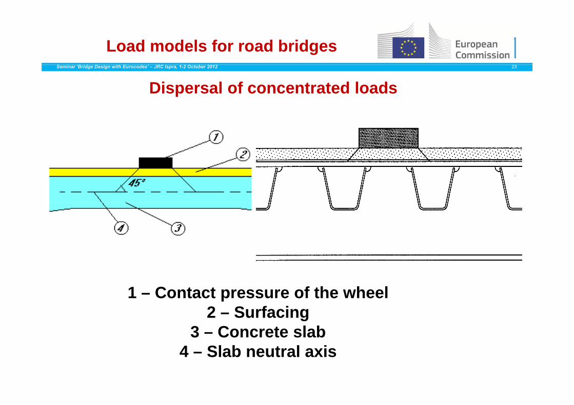
Dispersal of concentrated loads
1 – Contact pressure of the wheel1 – Contact pressure of the wheel2 – Surfacing
3 – Concrete slab4 – Slab neutral axis
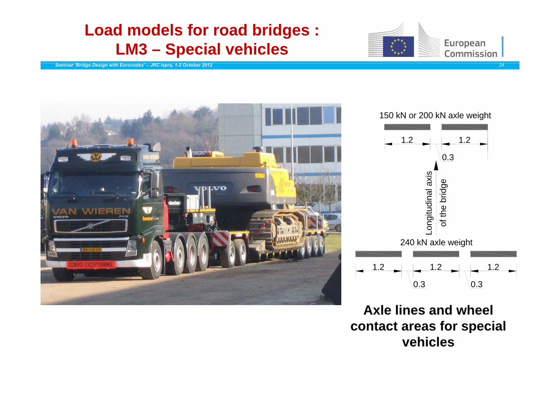
Load models for road bridges : LM3 – Special vehicles
Seminar ‘Bridge Design with Eurocodes’ – JRC Ispra, 1-2 October 2012 24
1.2 1.2
150 kN or 200 kN axle weight
nal a
xis
ridge
0.3
Long
itudi
nof
the
b
240 kN axle weight
1.2
0.3
1.2
240 kN axle weight
1.2
0.3 0 30 3
Axle lines and wheel contact areas for special p
vehicles

Load models for road bridges : LM3 – Special vehicles
Seminar ‘Bridge Design with Eurocodes’ – JRC Ispra, 1-2 October 2012 25
Arrangement of special vehicle onspecial vehicle on the carriageway
Simultaneity of special vehicles and load model n. 1and load model n. 1
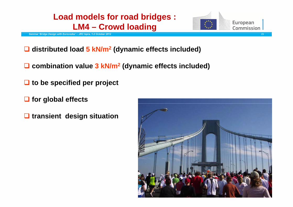
Load models for road bridges : LM4 – Crowd loading
Seminar ‘Bridge Design with Eurocodes’ – JRC Ispra, 1-2 October 2012 26
distributed load 5 kN/m2 (dynamic effects included)
combination value 3 kN/m2 (dynamic effects included)
b ifi d j to be specified per project
for global effects
transient design situation
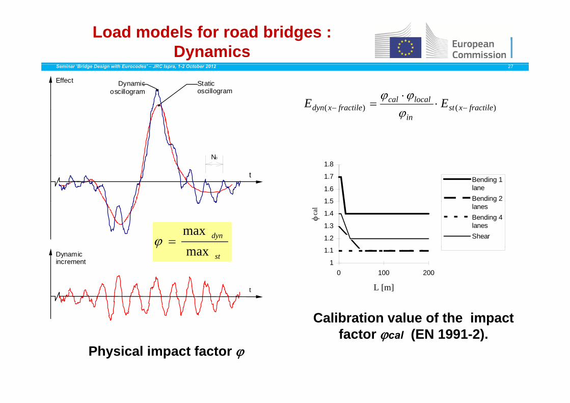
Load models for road bridges : Dynamics
Seminar ‘Bridge Design with Eurocodes’ – JRC Ispra, 1-2 October 2012 27
Static oscillogram
Effect Dynamic oscillogram
)()( fractilexstlocalcal
fractilexdyn EE
N
)()( fractilexstin
fractilexdyn
N0
t
1 5
1.6
1.7
1.8
Bending 1laneBending 2
dynmax 1.2
1.3
1.4
1.5
cal
glanesBending 4lanesShear
Dynamic increment
t
stmax
1
1.1
0 100 200
L [m]
Calibration value of the impact factor cal (EN 1991-2).acto ca ( 99 )
Physical impact factor
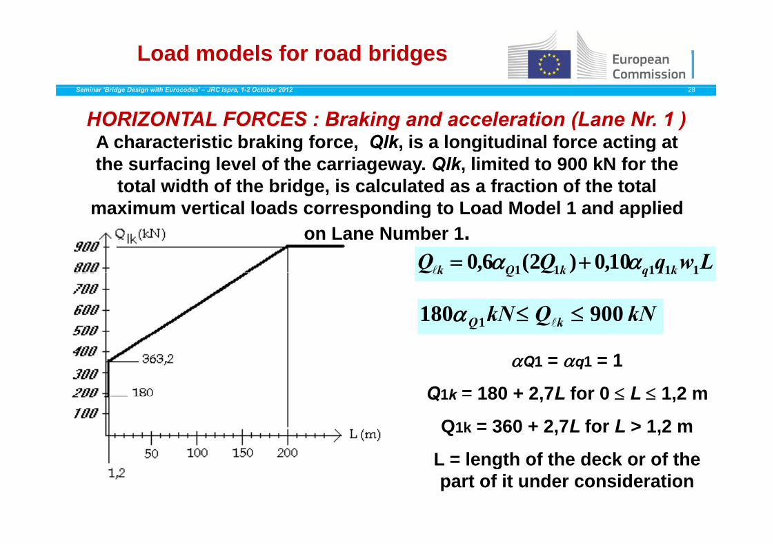
Load models for road bridgesSeminar ‘Bridge Design with Eurocodes’ – JRC Ispra, 1-2 October 2012 28
HORIZONTAL FORCES : Braking and acceleration (Lane Nr. 1 )A characteristic braking force, Qlk, is a longitudinal force acting at g , Q , g gthe surfacing level of the carriageway. Qlk, limited to 900 kN for the
total width of the bridge, is calculated as a fraction of the total maximum vertical loads corresponding to Load Model 1 and applied
LwqQQ kqkQk 11111 10,0)2(6,0
maximum vertical loads corresponding to Load Model 1 and applied on Lane Number 1.
qQQ kqkQk 11111 )(
kNQkN kQ 900180 1
Q1 = q1 = 1
Q1k = 180 + 2 7L for 0 L 1 2 mQ1k 180 + 2,7L for 0 L 1,2 m
Q1k = 360 + 2,7L for L > 1,2 m
L = length of the deck or of theL = length of the deck or of the part of it under consideration

Load models for road bridgesSeminar ‘Bridge Design with Eurocodes’ – JRC Ispra, 1-2 October 2012 29
HORIZONTAL FORCES : Centrifugal forces
for r < 200 mkNQQ vfk 2,0
for 200 r < 1500 mkNrQQ vfk /40
for r > 1500 m0fkQ
r : horizontal radius of curvature of the carriageway centreline [m] Qfk should be taken as a
transverse force acting at theQv : total maximum weight of vertical concentrated loads of the tandem systems of LM1
finished carriageway level andradially to the axis of thecarriageway.y
i
ikQi Q )2(
ca age ay
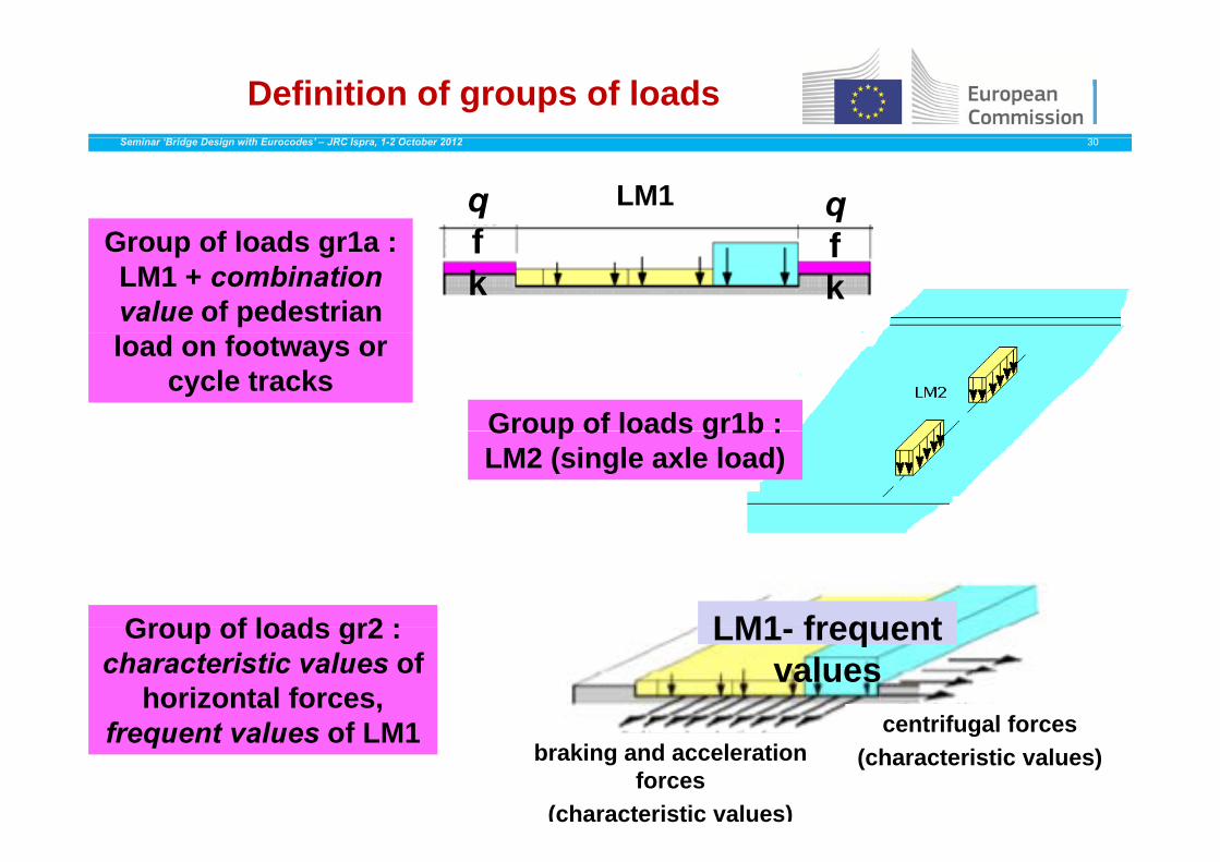
Definition of groups of loadsSeminar ‘Bridge Design with Eurocodes’ – JRC Ispra, 1-2 October 2012 30
G f l d 1LM1q
fqfGroup of loads gr1a :
LM1 + combination value of pedestrian
fk
fk
load on footways or cycle tracks
Group of loads gr1b :Group of loads gr1b : LM2 (single axle load)
Group of loads gr2 : LM1 frequentGroup of loads gr2 : characteristic values of
horizontal forces, f t l f LM1 centrifugal forces
LM1- frequent values
frequent values of LM1 centrifugal forces(characteristic values)braking and acceleration
forces(characteristic values)
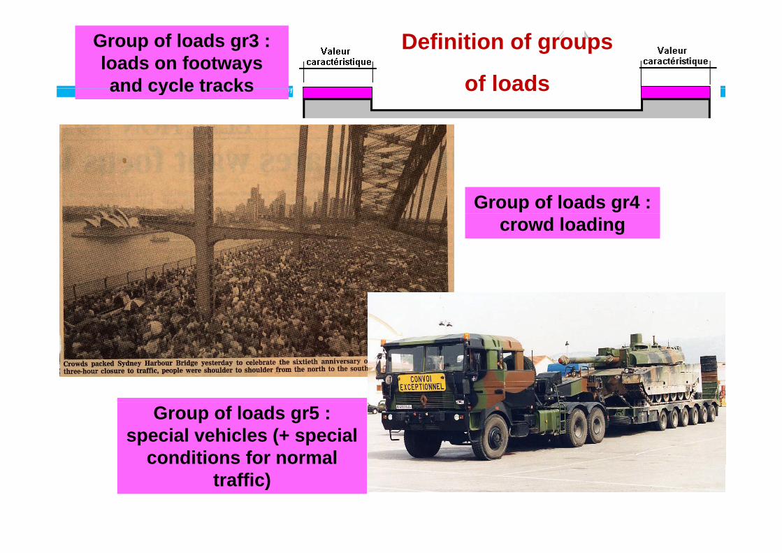
Group of loads gr3 : loads on footways and cycle tracks
Definition of groups
of loadsSeminar ‘Bridge Design with Eurocodes’ – JRC Ispra, 1-2 October 2012 31and cycle tracks of loads
Group of loads gr4 : crowd loading
Group of loads gr5 : special vehicles (+ special
conditions for normal traffic)

Table 4.4a – Assessment of groups of traffic loads (characteristic values of
h l i i )Seminar ‘Bridge Design with Eurocodes’ – JRC Ispra, 1-2 October 2012 32the multi-component action)
CARRIAGEWAY FOOTWAYS AND
CYCLE TRACKS
Load type Vertical forces Horizontal forces Vertical forces only
Reference 4 3 2 4 3 3 4 3 4 4 3 5 4 4 1 4 4 2 5 3 2-(1)Reference 4.3.2 4.3.3 4.3.4 4.3.5 4.4.1 4.4.2 5.3.2 (1)Load system LM1
(TS and UDL systems)
LM2 (Single axle)
LM3 (Special vehicles)
LM4 (Crowd loading)
Braking and acceleration forces
Centrifugal and transverse forces
Uniformly Distributed load
gr1a Characteristic a) a) Combination b)values value b)
gr1b Characteristic value
gr2 Frequent valuesb)
Characteristic value
Characteristic value
d)Groups of Loads
gr3 d) Characteristic value c)
gr4 Characteristic value
Characteristic value b)
gr5 See Annex A Characteristic value
value
Dominant component action (designated as component associated with the group) a) If specified, may be defined in the National Annex. b) May be defined in the National Annex. Recommended value : 3 kN/m2. c) See 5.3.2.1-(3). One footway only should be considered to be loaded if the effect is more unfavourable than the effect of two loaded footways.footways.d) This group is irrelevant if gr4 is considered.
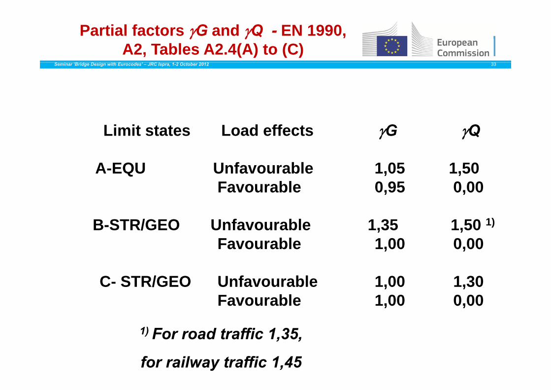
Partial factors G and Q - EN 1990, A2, Tables A2.4(A) to (C)
Seminar ‘Bridge Design with Eurocodes’ – JRC Ispra, 1-2 October 2012 33
Limit states Load effects G Q
A-EQU Unfavourable 1,05 1,50Favourable 0,95 0,00
B-STR/GEO Unfavourable 1,35 1,50 1)
F bl 1 00 0 00Favourable 1,00 0,00
C- STR/GEO Unfavourable 1 00 1 30C- STR/GEO Unfavourable 1,00 1,30Favourable 1,00 0,00
1) ff 1 31) For road traffic 1,35,
for railway traffic 1,45

factors for road bridgesSeminar ‘Bridge Design with Eurocodes’ – JRC Ispra, 1-2 October 2012 34
Action Symbol 0 1 2
gr 1a (LM1) TS 0 75 0 75 0
Traffic loads (see EN 1991 2
gr 1a (LM1) TS 0,75 0,75 0gr 1a (LM1) UDL 0,40 0,40 0gr1b (single axle) 0 0 75 0(see EN 1991-2,
Table 4.4)gr1b (single axle) 0 0,75 0
gr2 (horizontal forces) 0 0 0gr3 (pedestrian loads) 0 0,4 0gr3 (pedestrian loads) 0 0,4 0gr4 (LM4 crowd) 0 0 0gr5 (LM3 spec.vehicl.) 0 1 0g ( p )
Wind forces Fw persistent (execut.) 0,6 (0,8) 0,2 0
Thermal actions T 0,6 0,6 0,5Thermal actions T 0,6 0,6 0,5Snow loads Sn (during execution) 0,8 - 0Construction Qca 1 - 1loads
ca

Combination rules for ULSSeminar ‘Bridge Design with Eurocodes’ – JRC Ispra, 1-2 October 2012 35
• Persistent and transient design situation –
fundamental action combinations
)10.6(k011
1k1kk iii
Qij
QPjGj QQPG
or
(A)
)a10.6(k011
kk iii
Qij
PjGj QPG
or
(B)j
(6.10b)k011
1k1kk iii
Qij
QPjGjj QQPG
)b11.6()( k21k2111dkk iij QQorAPG • Accidental design situation
)()( k1
21
1k2111dkk ii
ij
j QQ
• Seismic design situation
)b12.6(k1
21
Edkk ii
ij
j QAPG
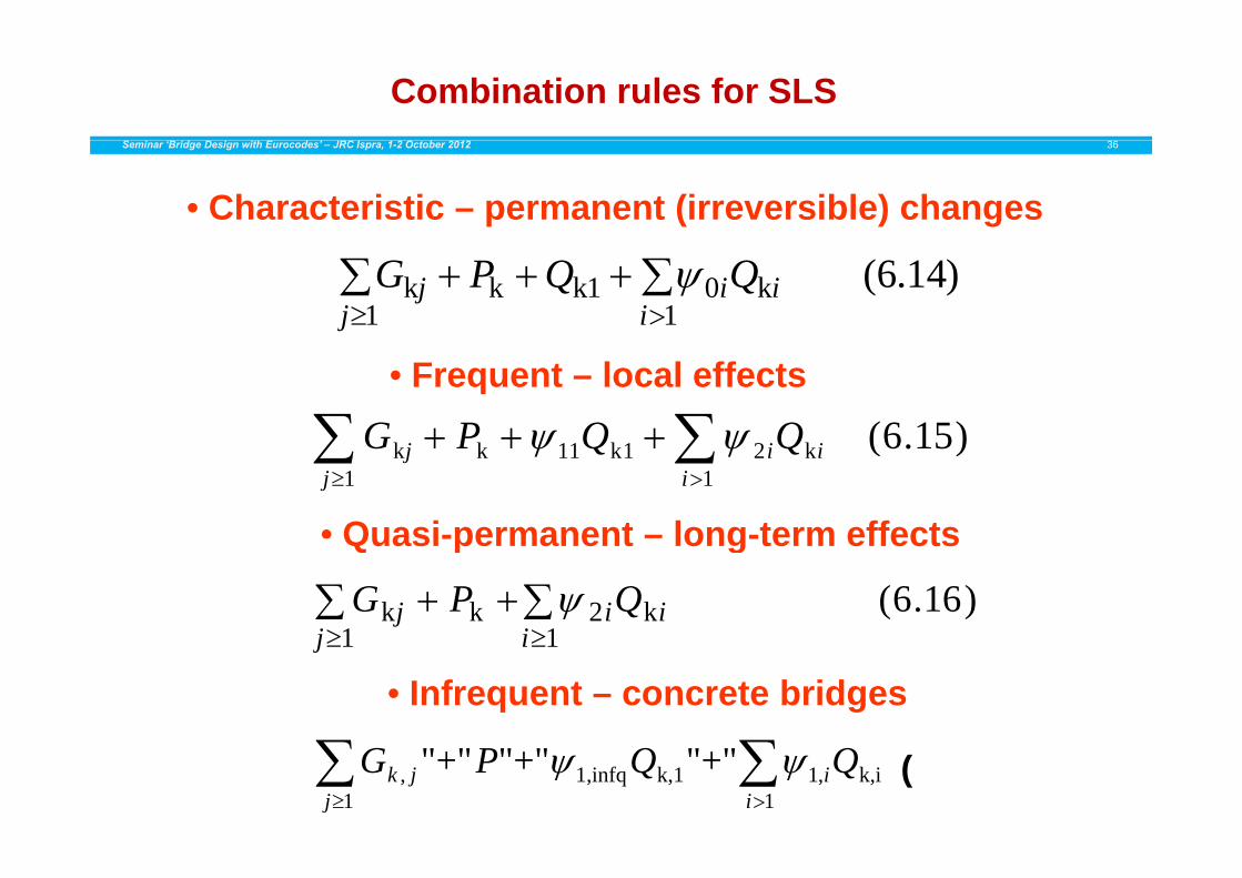
Combination rules for SLSSeminar ‘Bridge Design with Eurocodes’ – JRC Ispra, 1-2 October 2012 36
• Characteristic – permanent (irreversible) changes
)14.6(k1
01
1kkk ii
ij
j QQPG
)156(QQPG • Frequent – local effects
)15.6(k1
21
1k11kk ii
ij
j QQPG
• Quasi-permanent – long-term effectsQuasi-permanent long-term effects
)16.6(k1
21
kk ii
ij
j QPG
11 ij
• Infrequent – concrete bridges
k,i1
,1k,11,infq1
, "+""+""+" QQPGi
ij
jk
(A2.1b)
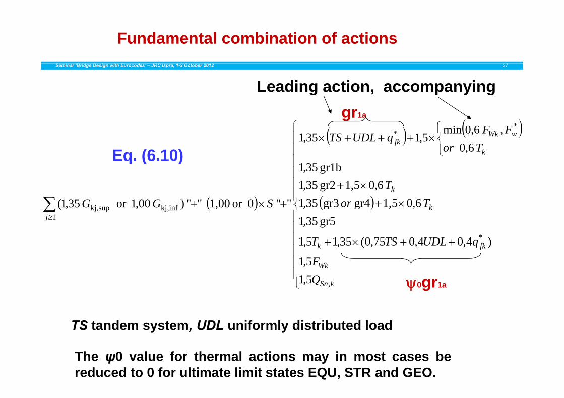
Fundamental combination of actions Seminar ‘Bridge Design with Eurocodes’ – JRC Ispra, 1-2 October 2012 37
Leading action, accompanying
k
wWkfk Tor
FFqUDLTS
**
6,0 , 6,0min
5,135,1Eq (6 10)
gr1a
k
k
T6014331
6,01,5gr2 35,1gr1b 35,1
Eq. (6.10)
fkk
kj
qUDLTST
TorSGG
*
1kj,infkj,sup
)4,04,075,0(35,15,1
gr5 35,16,01,5gr4gr3 35,1""0or 1,00"") 00,1or 35,1(
kSn
Wk
fkk
QF
qUDLTST
,5,15,1
)4,04,075,0(35,15,1
0gr1a g
TS tandem system, UDL uniformly distributed load
The ψ0 value for thermal actions may in most cases bereduced to 0 for ultimate limit states EQU, STR and GEO.

Characteristic combination of actions (SLS) Seminar ‘Bridge Design with Eurocodes’ – JRC Ispra, 1-2 October 2012 38
Leading action, accompanying
k
wWkfk Tor
FFqUDLTS
**
60, 6,0min
gr1a
k
k
T
Tor
6,0gr2gr1b
6,0
k
k
jTorSGG
1kj,infkj,sup
gr5 6,0gr4 gr3
,g""0or 00,1"")or(
Wk
fkk
F
qUDLTST * )4,04,075,0(
gr1 kSnQ ,
0gr1a
TS tandem system, UDL uniformly distributed load
The ψ0 value for thermal actions may in most cases bereduced to 0 for ultimate limit states EQU, STR and GEO.
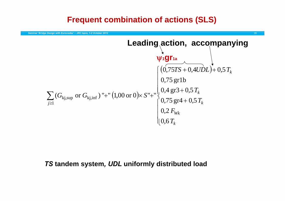
Frequent combination of actions (SLS) Seminar ‘Bridge Design with Eurocodes’ – JRC Ispra, 1-2 October 2012 39
Leading action, accompanying
kTUDLTS
1b0 75 5,04,075,0
1gr1a
k
TT
SGG50gr4750 5,0gr3 0,4
gr1b0,75
""0or 00,1"")or( kj,infkj,sup
k
Wk
kj
TF
T
6,0 2,0
5,0gr475,01
k,
TS tandem system, UDL uniformly distributed load

Quasi permanent-combination of actions (SLS) Seminar ‘Bridge Design with Eurocodes’ – JRC Ispra, 1-2 October 2012 40
Leading action (no accompanying)
kTSGG 5,0""0or 00,1"")or( kj,infkj,sup j 1
j,j, p
FatigueSeminar ‘Bridge Design with Eurocodes’ – JRC Ispra, 1-2 October 2012 41
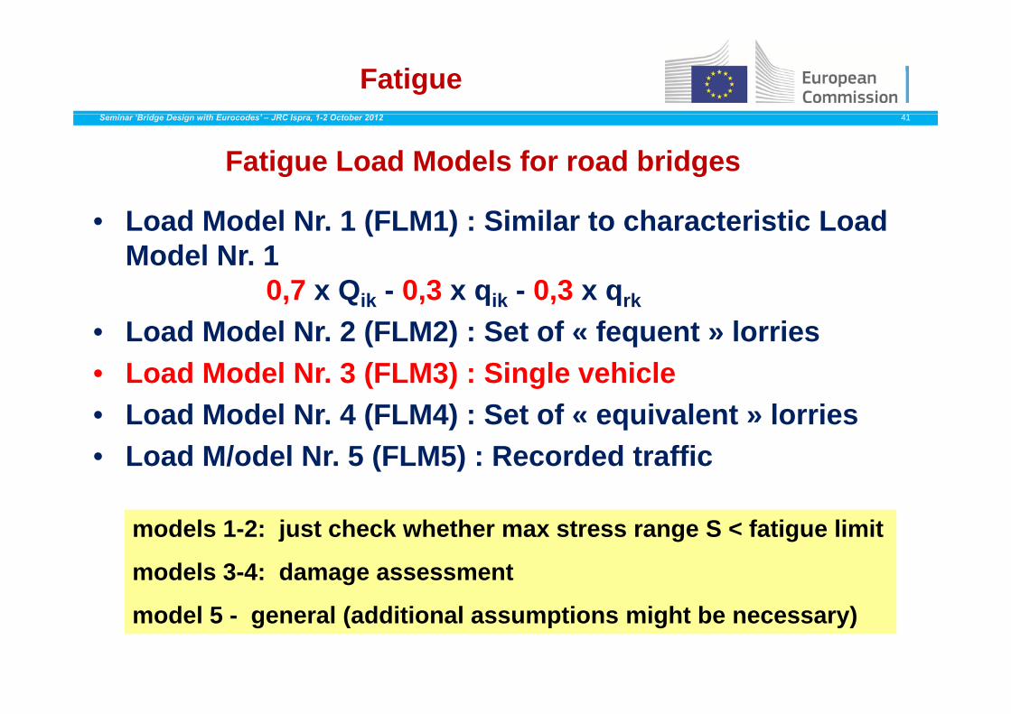
Fatigue Load Models for road bridges
• Load Model Nr. 1 (FLM1) : Similar to characteristic Load Model Nr. 1
0,7 x Qik - 0,3 x qik - 0,3 x qrk
• Load Model Nr. 2 (FLM2) : Set of « fequent » lorries• Load Model Nr. 3 (FLM3) : Single vehicle• Load Model Nr. 4 (FLM4) : Set of « equivalent » lorries• Load M/odel Nr. 5 (FLM5) : Recorded traffic
models 1-2: just check whether max stress range S < fatigue limit
models 3-4: damage assessment
model 5 - general (additional assumptions might be necessary)
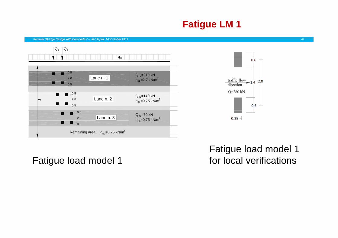
Fatigue LM 1Seminar ‘Bridge Design with Eurocodes’ – JRC Ispra, 1-2 October 2012 42
QikQik
qik
Lane n. 1Q =210 kNq =2.7 kN/m
1k
1k
0.5
2.0
0.5
2
Lane n. 20.5
2.0
0.5
Q =140 kN2kq =0.75 kN/m2k
2
Lane n. 3Q =70 kN3kq =0 75 kN/m2
0.5
2.0
w
F ti l d d l 1
Lane n. 3 q =0.75 kN/m3k2
Remaining area q =0.75 kN/mrk2
0.5
Fatigue load model 1Fatigue load model 1 for local verifications

Fatigue LM 2Seminar ‘Bridge Design with Eurocodes’ – JRC Ispra, 1-2 October 2012 43
Fatigue load model n. 2 – frequent set of lorriesLORRY
SILHOUETTEInteraxles
[m]Frequentaxle loads
[kN]
Wheel type (see table 3)
4 5 90 A
Wheel axle type Geometrical definition
s4.5 90190
AB
4.201.30
80140140
ABB
A
Long
itudi
nal a
xis
of th
e br
idge
1.782 2
3.205,201.301.30
90180120120
ABCC
20.220.
32 0.22 0.32
axis
ge2 2120 C
3.406.001 80
90190140
ABB
B
Long
itudi
nal
of th
e br
idg
2 0 22
0.32
0.22
0.32
0.220 22
0.54 0.54
1.80 140140
BB
4.803.604 40
90180120
ABC
2 0.220.22
C tudi
nal a
xis
he b
ridge
4.401.30
120110110
CCC
Long
itof
th
2
1.730.270.
32 0.27 0.32
Fatigue LM 3Seminar ‘Bridge Design with Eurocodes’ – JRC Ispra, 1-2 October 2012 44
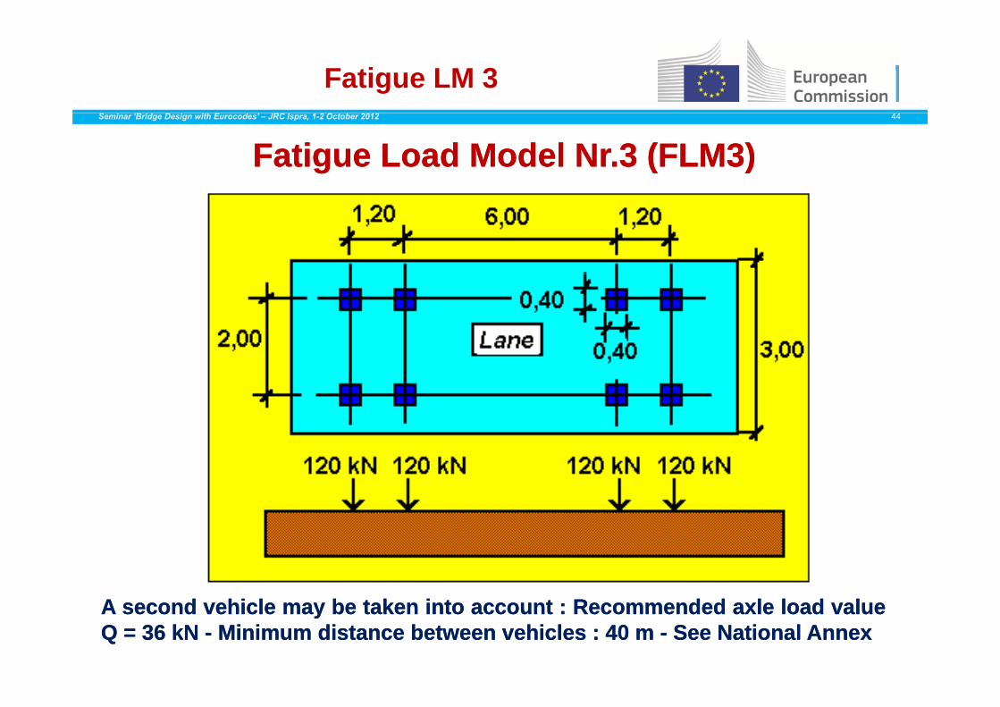
Fatigue Fatigue LoadLoad Model Nr.3 (FLM3)Model Nr.3 (FLM3)
AA secondsecond vehiclevehicle maymay bebe takentaken intointo accountaccount :: RecommendedRecommended axleaxle loadload valuevalueQQ == 3636 kNkN -- MinimumMinimum distancedistance betweenbetween vehiclesvehicles :: 4040 mm -- SeeSee NationalNational AnnexAnnex
Fatigue LM 4Seminar ‘Bridge Design with Eurocodes’ – JRC Ispra, 1-2 October 2012 45
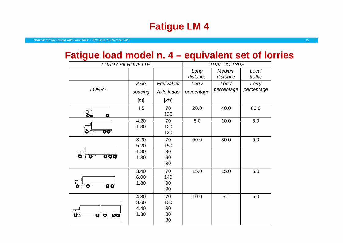
Fatigue load model n. 4 – equivalent set of lorriesLORRY SILHOUETTE TRAFFIC TYPE
Longdistance
Mediumdistance
Localtraffic
LORRYAxle
spacing
Equivalent
Axle loads
Lorry
percentage
Lorry percentage
Lorry percentagep g
[m] [kN]
p g
4.5 70130
20.0 40.0 80.0
4 20 70 5 0 10 0 5 04.201.30
70120120
5.0 10.0 5.0
3.205.20
70150
50.0 30.0 5.0
1.301.30
909090
3.406 00
70140
15.0 15.0 5.06.001.80
1409090
4.803.60
70130
10.0 5.0 5.0
4.401.30
908080
EN 1991-1-5: THERMAL ACTIONSSeminar ‘Bridge Design with Eurocodes’ – JRC Ispra, 1-2 October 2012 46
• Forward• Section 1 General• Section 1 – General• Section 2 – Classification of actions• Section 3 – Design situations• S ti 4 R t ti f ti• Section 4 – Representation of actions• Section 5 – Temperature changes in buildings• Section 6 – Temperature changes in bridges• Section 7 – Temperature changes in industrial chimneys,
pipelines, silos, tanks and cooling towers• Annex A (normative) – Isotherms of national minimum and ( )
maximum shade air temperatures.• Annex B (normative) – Temperature differences for various
surfacing depthssurfacing depths• Annex C (informative) – Coefficients of linear expansion• Annex D (informative) – Temperature profiles in buildings and
other construction worksother construction works
EN 1991-1-5: THERMAL ACTIONSSeminar ‘Bridge Design with Eurocodes’ – JRC Ispra, 1-2 October 2012 47
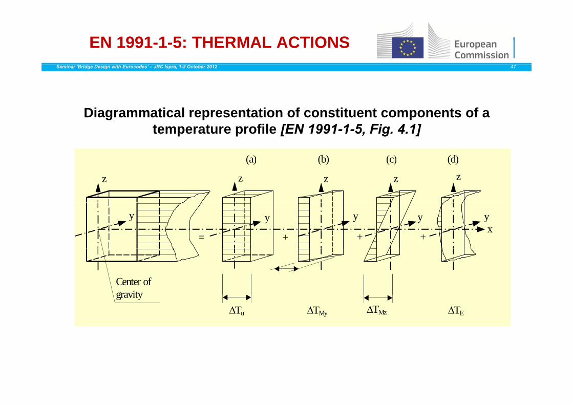
Diagrammatical representation of constituent components of a
( ) (b) ( ) (d)
Diagrammatical representation of constituent components of a temperature profile [EN 1991-1-5, Fig. 4.1]
z z z z z
(a) (b) (c) (d)
x y y y y y
= + + +
Center of gravitygravity
Tu TMy TMz TE
EN 1991-1-5: THERMAL ACTIONS -Bridge Types
Seminar ‘Bridge Design with Eurocodes’ – JRC Ispra, 1-2 October 2012 48
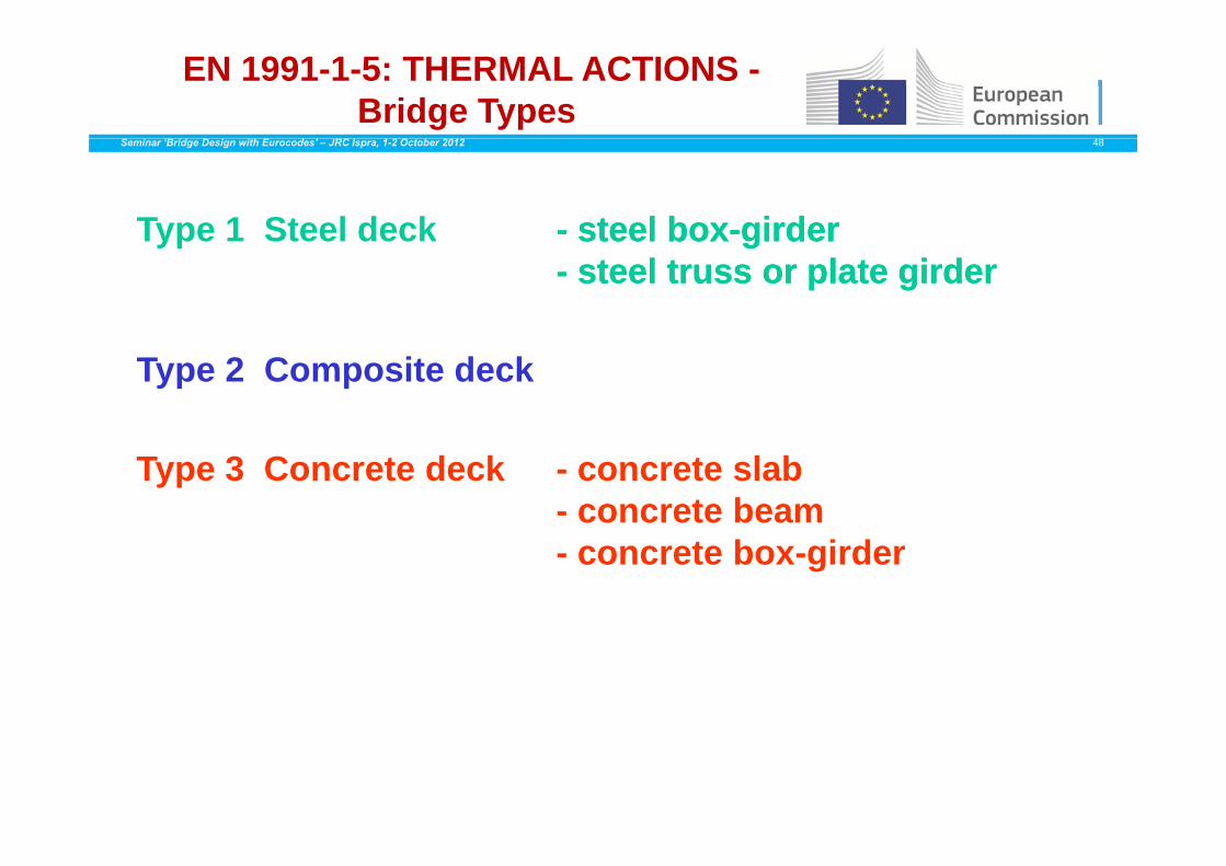
Type 1 Steel deck - steelsteel boxbox--girdergirderType 1 Steel deck steelsteel boxbox girdergirder-- steelsteel trusstruss or plate or plate girdergirder
Type 2 Composite deck
Type 3 Concrete deck - concrete slab- concrete beam- concrete box-girder

EN 1991-1-5: THERMAL ACTIONS Determination of thermal effects
Seminar ‘Bridge Design with Eurocodes’ – JRC Ispra, 1-2 October 2012 49
70maximum
Te.maxTe.min
T 1 t l
50
60Type 1 - steel
Type 2 - compositeType 3 concrete
30
40Type 3 - concrete
Correlation betweenCorrelation between
0
10
20min/max shade air min/max shade air
temperature temperature ((Tmin/TmaxTmin/Tmax))
-20
-10
0 ((Tmin/TmaxTmin/Tmax))
AndAnd
i / if b idi / if b id
-40
-30
20
TT
min/max uniform bridge min/max uniform bridge temperature component temperature component
((Te.min/Te.maxTe.min/Te.max))
-50-50 -40 -30 -20 -10 0 10 20 30 40 50
minimumTmaxTmaxTminTmin
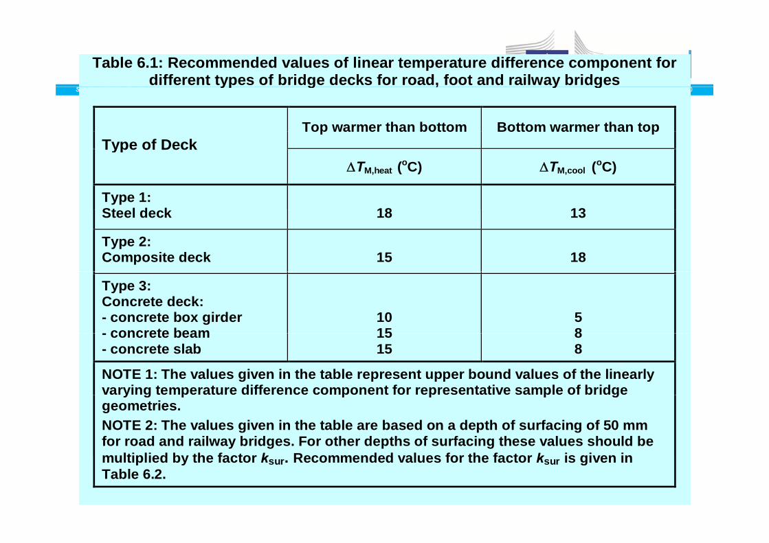
Table 6.1: Recommended values of linear temperature difference component for different types of bridge decks for road, foot and railway bridges
Seminar ‘Bridge Design with Eurocodes’ – JRC Ispra, 1-2 October 2012 50yp g , y g
Top warmer than bottom Bottom warmer than top Type of DeckType of Deck
TM,heat (oC) TM,cool (oC)
Type 1: St l d k
18
13Steel deck 18 13
Type 2: Composite deck
15
18
Type 3: Concrete deck: - concrete box girder - concrete beam
10 15
5 8- concrete beam
- concrete slab 1515
88
NOTE 1: The values given in the table represent upper bound values of the linearly varying temperature difference component for representative sample of bridge y g p p p p ggeometries. NOTE 2: The values given in the table are based on a depth of surfacing of 50 mm for road and railway bridges. For other depths of surfacing these values should be multiplied by the factor k Recommended values for the factor k is given inmultiplied by the factor ksur. Recommended values for the factor ksur is given in Table 6.2.
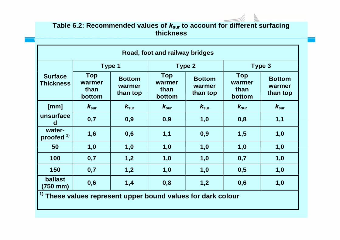
Table 6.2: Recommended values of ksur to account for different surfacing thickness
Seminar ‘Bridge Design with Eurocodes’ – JRC Ispra, 1-2 October 2012 51
Road, foot and railway bridges
Type 1 Type 2 Type 3Type 1 Type 2 Type 3Surface
ThicknessTop
warmer than
Bottom warmer than top
Top warmer
than Bottom warmer than top
Top warmer
than Bottom warmer than topbottom than top bottom than top bottom than top
[mm] ksur ksur ksur ksur ksur ksur unsurface 0 7 0 9 0 9 1 0 0 8 1 1d 0,7 0,9 0,9 1,0 0,8 1,1
water-proofed 1) 1,6 0,6 1,1 0,9 1,5 1,0
50 1 0 1 0 1 0 1 0 1 0 1 050 1,0 1,0 1,0 1,0 1,0 1,0
100 0,7 1,2 1,0 1,0 0,7 1,0
150 0,7 1,2 1,0 1,0 0,5 1,0 ballast
(750 mm) 0,6 1,4 0,8 1,2 0,6 1,0 1) These values represent upper bound values for dark colour

STEEL BRIDGESSeminar ‘Bridge Design with Eurocodes’ – JRC Ispra, 1-2 October 2012 52
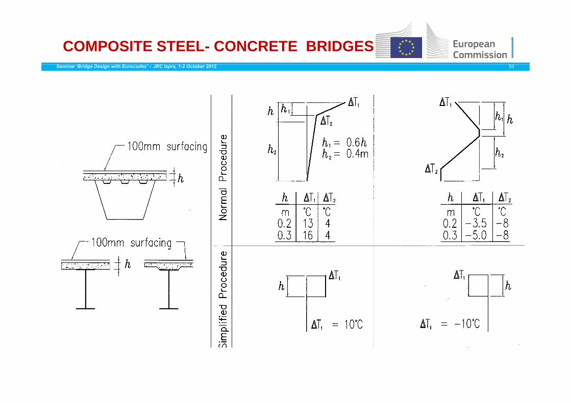
COMPOSITE STEEL- CONCRETE BRIDGESSeminar ‘Bridge Design with Eurocodes’ – JRC Ispra, 1-2 October 2012 53
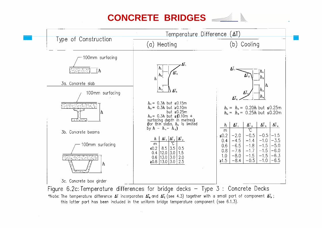
CONCRETE BRIDGES
Seminar ‘Bridge Design with Eurocodes’ – JRC Ispra, 1-2 October 2012 54

EN 1991-1-5: THERMAL ACTIONSAdditional rules
Seminar ‘Bridge Design with Eurocodes’ – JRC Ispra, 1-2 October 2012 55
Simultaneity of uniform and temperature differencecomponents (recommended values)
)()(750
)(35,0)( ,exp,,, conNNcoolMheatM
TTTT
TorTTorT
components (recommended values)
)()(75,0 ,exp,,, conNNcoolMheatM TorTTorT
Differences in the uniform temperature component between different structural elements :- 15°C between main structural elements (e.g. tie and arch); andarch); and- 10°C and 20°C for light and dark colour respectively between suspension/stay cables and deck (or tower).between suspension/stay cables and deck (or tower).
Temperature differences between the inner and outer web walls of large concrete box girder bridges :web walls of large concrete box girder bridges :Recommended value 15°C
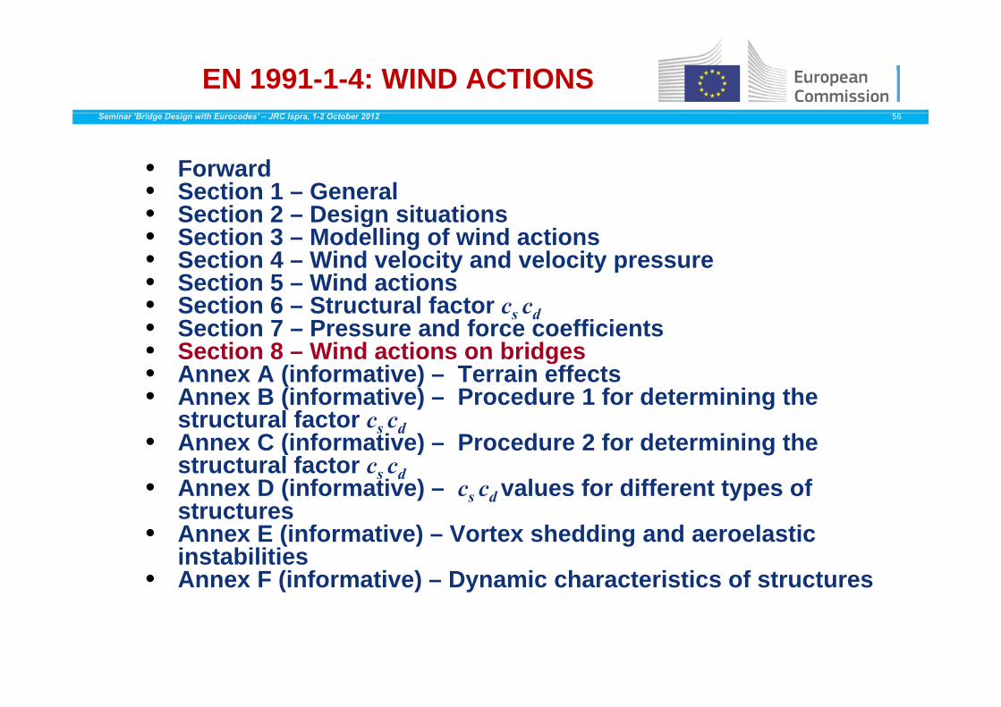
EN 1991-1-4: WIND ACTIONSSeminar ‘Bridge Design with Eurocodes’ – JRC Ispra, 1-2 October 2012 56
• Forward• Section 1 – General• Section 1 – General• Section 2 – Design situations• Section 3 – Modelling of wind actions• Section 4 – Wind velocity and velocity pressure
S• Section 5 – Wind actions• Section 6 – Structural factor cs cd• Section 7 – Pressure and force coefficients• Section 8 – Wind actions on bridgesSection 8 – Wind actions on bridges• Annex A (informative) – Terrain effects• Annex B (informative) – Procedure 1 for determining the
structural factor cs cdA C (i f ti ) P d 2 f d t i i th• Annex C (informative) – Procedure 2 for determining the structural factor cs cd• Annex D (informative) – cs cdvalues for different types of structuresstructures
• Annex E (informative) – Vortex shedding and aeroelasticinstabilities
• Annex F (informative) – Dynamic characteristics of structures
EN 1991-1-4: WIND ACTIONS (ON BRIDGE DECK AND PIERS)
Seminar ‘Bridge Design with Eurocodes’ – JRC Ispra, 1-2 October 2012 57
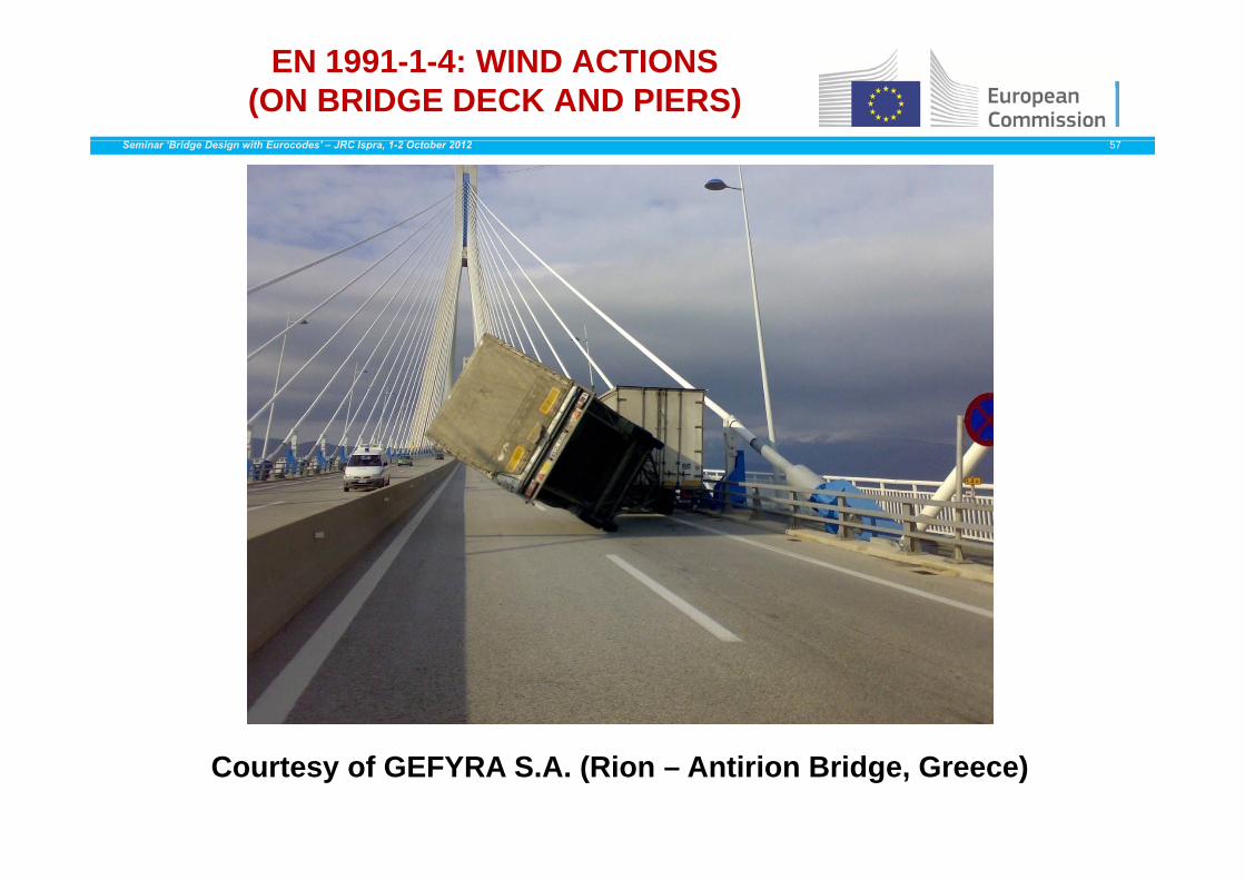
Courtesy of GEFYRA S.A. (Rion – Antirion Bridge, Greece)

EN 1991-1-4: WIND ACTIONS (ON BRIDGE DECK AND PIERS)
Seminar ‘Bridge Design with Eurocodes’ – JRC Ispra, 1-2 October 2012 58
The following cases should typically be handled :The following cases should typically be handled :
• Bridge during its service life, without traffic
• Bridge during its service life, with traffic
• Bridge under construction (finished and most critical case)This design situation might be critical in case of varyingt t l tstructural system
EN 1991-1-4: WIND ACTIONS (ON BRIDGE DECK AND PIERS)
Seminar ‘Bridge Design with Eurocodes’ – JRC Ispra, 1-2 October 2012 59
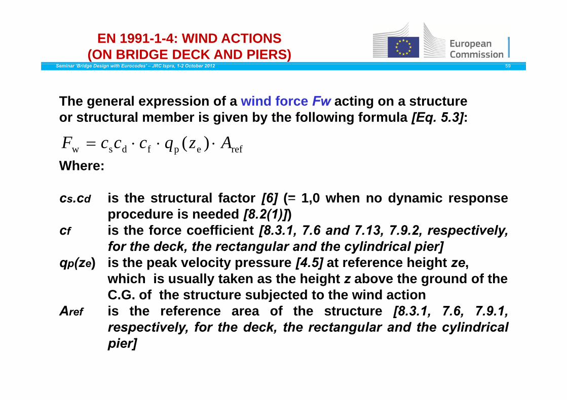
The general expression of a wind force Fw acting on a structureor structural member is given by the following formula [Eq. 5.3]:
refepfdsw )( AzqcccF Where:
cs cd is the structural factor [6] (= 1 0 when no dynamic responsecs.cd is the structural factor [6] ( 1,0 when no dynamic responseprocedure is needed [8.2(1)])
cf is the force coefficient [8.3.1, 7.6 and 7.13, 7.9.2, respectively,for the deck the rectangular and the cylindrical pier]for the deck, the rectangular and the cylindrical pier]
qp(ze) is the peak velocity pressure [4.5] at reference height ze, which is usually taken as the height z above the ground of the C G f th t t bj t d t th i d tiC.G. of the structure subjected to the wind action
Aref is the reference area of the structure [8.3.1, 7.6, 7.9.1,respectively, for the deck, the rectangular and the cylindricalpier]

EN 1991-1-4: WIND ACTIONS (ON BRIDGE DECK AND PIERS)
Seminar ‘Bridge Design with Eurocodes’ – JRC Ispra, 1-2 October 2012 60
The peak velocity pressure qp(z) at height z, includes the mean andthe short-term (turbulent) fluctuations and is expressed by theformula [4.8]:
Where:
be2mvp )()(
21)(71)( qzczvzIzq
Where:
ρ is the air density (which depends on the altitude, temperatureand barometric pressure to be expected in the region duringand barometric pressure to be expected in the region duringwind storms; the recommended value used is 1,25 kg/m3
vm(z) is the mean wind velocity at a height z above the ground [4.3]I ( ) i th t b l i t it t h i ht d fi d [4 4(1)] thIv(z) is the turbulence intensity at height z, defined [4.4(1)] as the
ratio of the standard deviation of the turbulence divided bethe mean velocity, and is expressed by the following formula[4.7]
ce(z) is the exposure factor at a height z
EN 1991-1-4: WIND ACTIONS (ON BRIDGE DECK AND PIERS)
Seminar ‘Bridge Design with Eurocodes’ – JRC Ispra, 1-2 October 2012 61
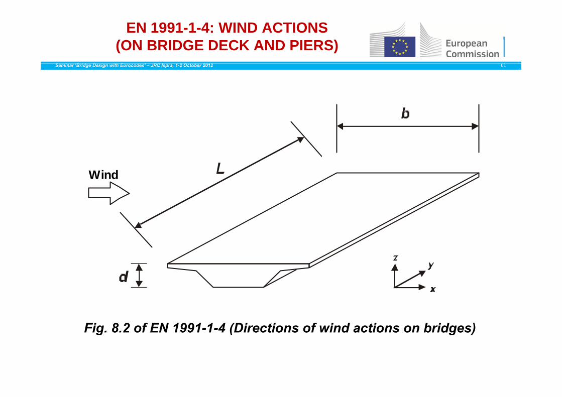
Wind
Fig. 8.2 of EN 1991-1-4 (Directions of wind actions on bridges)g ( g )
EN 1991-1-4: WIND ACTIONS (ON BRIDGE DECK AND PIERS)
Seminar ‘Bridge Design with Eurocodes’ – JRC Ispra, 1-2 October 2012 62
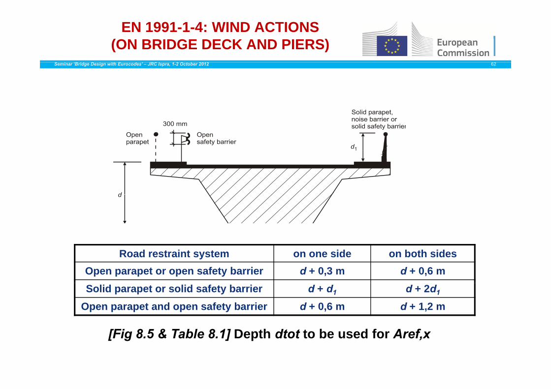
Road restraint system on one side on both sidesOpen parapet or open safety barrier d + 0,3 m d + 0,6 mSolid parapet or solid safety barrier d + d1 d + 2d1
Open parapet and open safety barrier d + 0,6 m d + 1,2 m
[Fig 8.5 & Table 8.1] Depth dtot to be used for Aref,x

EN 1991-1-4: WIND ACTIONS (ON BRIDGE DECK AND PIERS)
Seminar ‘Bridge Design with Eurocodes’ – JRC Ispra, 1-2 October 2012 63
AdditionalAdditional heightsheights forfor thethe calculationcalculation ofof AAref xref x (d*(d* == 22 mm ;; d**d** == 44 m)m)AdditionalAdditional heightsheights forfor thethe calculationcalculation ofof AAref,xref,x (d(d == 22 mm ;; dd == 44 m)m)
forfor bridgesbridges duringduring theirtheir serviceservice lifelife withwith traffictraffic

EN 1991-1-4: WIND ACTIONS (ON BRIDGE DECK AND PIERS)
Seminar ‘Bridge Design with Eurocodes’ – JRC Ispra, 1-2 October 2012 64
bridge type
a) construction phase or open parapets
trusses separately
construction phase or open parapets (more than 50% open) b) with parapets or barrier or traffic
[Fig. 8.3] Force coefficient cfx,0 for bridges
EN 1991-1-4: WIND ACTIONS (ON BRIDGE DECK AND PIERS)
Seminar ‘Bridge Design with Eurocodes’ – JRC Ispra, 1-2 October 2012 65
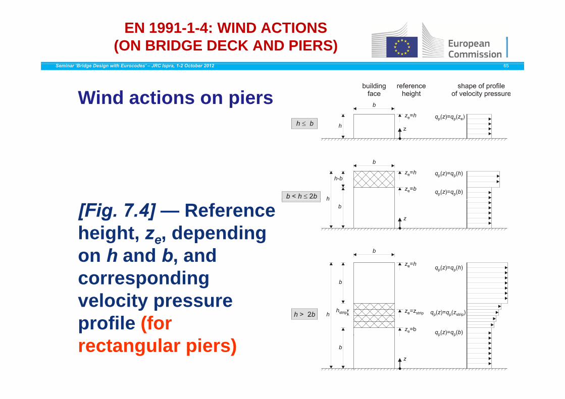
Wind actions on piers
[Fig. 7.4] — Reference height, ze, depending on h and b, and corresponding velocity pressure profile (for rectangular piers)

EN 1991-1-4: WIND ACTIONS (ON BRIDGE DECK AND PIERS)
Seminar ‘Bridge Design with Eurocodes’ – JRC Ispra, 1-2 October 2012 66
To resume:
To determine the wind actions on bridge decks and piers, itgseems convenient to follow successively the following steps:
• Determine vb (by choosing vb,0, cdir,cseason and cprob, ifDetermine vb (by choosing vb,0, cdir,cseason and cprob, ifrelevant); qb may also be determined at this stage
• Determine vm (z) (by choosing terrain category and referenceheight z to evaluate cr (z) and co (z))height z to evaluate cr (z) and co (z))
• Determine qp(z) (either by choosing directly ce(z), wherepossible, either by evaluating Iv(z), after choosing co(z))
• Determine F (after evaluating A f and by choosing cf and• Determine Fw (after evaluating Aref and by choosing cf andcs.cd, if relevant)

EN 1991-1-6: ACTIONS DURING EXECUTION
Seminar ‘Bridge Design with Eurocodes’ – JRC Ispra, 1-2 October 2012 67
• ForwardS G• Section 1 – General
• Section 2 – Classification of actions• Section 3 – Design situations and limit states• Section 3 – Design situations and limit states• Section 4 – Representation of actions• Annex A1 (normative) – Supplementary rules for ( ) pp y
buildings• Annex A2 (normative) – Supplementary rules for
b idbridges• Annex B (informative) – Actions on structures
during alteration reconstruction or demolitionduring alteration, reconstruction or demolition

ACTIONS DURING EXECUTION : CONSTRUCTION LOADS
Seminar ‘Bridge Design with Eurocodes’ – JRC Ispra, 1-2 October 2012 68
Construction Loads - QcSix different sourcesSix different sources
Qca Personnel and hand tools
Qcb Storage of movable items
Qcc Non-permanent equipment in position for use
Qcd Movable heavy machinery and equipment
Qce Accumulation of waste materials
Q Loads from part of structure in a temporary stateQcf Loads from part of structure in a temporary state
Construction loads Qc may be represented in the appropriate designsituations (see EN 1990), either, as one single variable action, or whereappropriate different types of construction loads may be grouped andapplied as a single variable action. Single and/or a grouping ofpp g g g p gconstruction loads should be considered to act simultaneously withnon construction loads as appropriate.
ACTIONS DURING EXECUTION : CONSTRUCTION LOADS Qca
Seminar ‘Bridge Design with Eurocodes’ – JRC Ispra, 1-2 October 2012 69
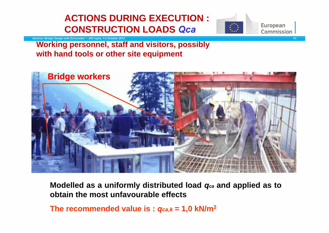
Working personnel, staff and visitors, possibly with hand tools or other site equipment
Bridge workersBridge workers
Modelled as a uniformly distributed load qca and applied as toobtain the most unfavourable effectsobtain the most unfavourable effects
The recommended value is : qca,k = 1,0 kN/m2

ACTIONS DURING EXECUTION : CONSTRUCTION LOADS: Qcb
Seminar ‘Bridge Design with Eurocodes’ – JRC Ispra, 1-2 October 2012 70
Storage ofStorage of moveablemoveable items,items, egeg. Building and. Building andStorage of Storage of moveablemoveable items, items, egeg. Building and . Building and construction construction materialsmaterials, , precastprecast elementselements, ,
and and equipmentequipment
Modelled as a free action and represented by a uniform deadload Qcb and a concentrated load Fcb
For bridges, the following values are recommended minimumvalues:
qcb,k = 0,2 kN/m2
Fcb,k = 100 kN

ACTIONS DURING EXECUTION : CONSTRUCTION LOADS: Qcc
Seminar ‘Bridge Design with Eurocodes’ – JRC Ispra, 1-2 October 2012 71
• Actions to be taken into account simultaneously during the casting of concrete may include:
• working personnel withworking personnel with small site equipment (Qca);
• formwork and load-bearing members (Qcc);
• the weight of fresh concrete (which is one example of(which is one example of Qcf), as appropriate.
ACTIONS DURING EXECUTION : casting of concrete
eSeminar ‘Bridge Design with Eurocodes’ – JRC Ispra, 1-2 October 2012 72e
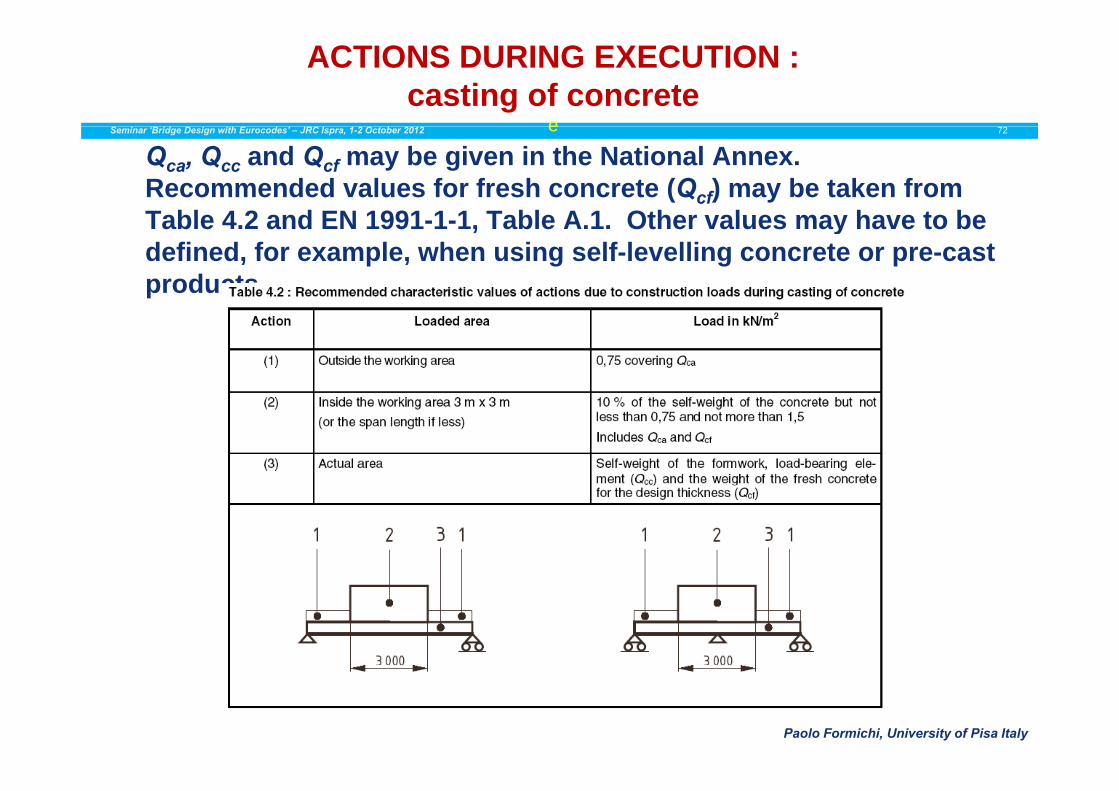
Qca, Qcc and Qcf may be given in the National Annex.Recommended values for fresh concrete (Qcf) may be taken from Table 4 2 and EN 1991 1 1 Table A 1 Other values may have to beTable 4.2 and EN 1991-1-1, Table A.1. Other values may have to be defined, for example, when using self-levelling concrete or pre-cast products.
Paolo Formichi, University of Pisa Italy

ACTIONS DURING EXECUTION: CONSTRUCTION LOADS Qcc
Seminar ‘Bridge Design with Eurocodes’ – JRC Ispra, 1-2 October 2012 73
Non permanent in position for use duringexectuion, either: - static (e.g. formwork panels,scaffolding falsework machinery containers)scaffolding, falsework, machinery, containers)or – during movement (e.g. travelling forms,launching girders and nose, counterweights
Unless more accurate information is available they may be modelledUnless more accurate information is available, they may be modelledby a uniformly distributed load with a recommended minimumcharacteristic value of qcc,k = 0,5 kN/m2
ACTIONS DURING EXECUTION :CONSTRUCTION LOADS Qcd
Seminar ‘Bridge Design with Eurocodes’ – JRC Ispra, 1-2 October 2012 74
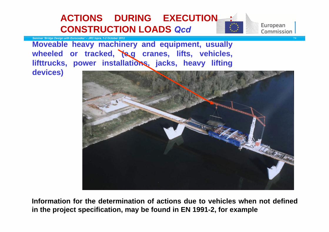
Moveable heavy machinery and equipment, usuallywheeled or tracked, (e.g cranes, lifts, vehicles,lifttrucks power installations jacks heavy liftinglifttrucks, power installations, jacks, heavy liftingdevices)
Information for the determination of actions due to vehicles when not definedin the project specification, may be found in EN 1991-2, for example

ACTIONS DURING EXECUTION : CONSTRUCTION LOADS Qce & Qcf
Seminar ‘Bridge Design with Eurocodes’ – JRC Ispra, 1-2 October 2012 75
Accumulation of waste materials (e.g. surplus construction Qmaterials excavated soil, or demolition Qce : materials
These loads are taken into account by considering
possible mass effects onpossible mass effects on horizontal, inclined and
vertical elements (such as walls)walls).
These loads may vary significantly, and over short ti i d d ditime periods, depending on types of materials, climatic
conditions, build-up and clearance rates.

ACTIONS DURING EXECUTION : CONSTRUCTION LOADS Qce & Qcf
Seminar ‘Bridge Design with Eurocodes’ – JRC Ispra, 1-2 October 2012 76
Qcf : Loads from parts of a structure in temporary states(under execution) before the final design actions take(under execution) before the final design actions takeeffect, such as loads from lifting operations.Taken into account and modelled according to the plannedexecution sequences, including the consequences of thosesequences (e.g. Loads and reverse load effects due to
ti l f t ti h bl )particular processes of construction, such as assemblage).

ACTIONS : SETTLEMENTSSeminar ‘Bridge Design with Eurocodes’ – JRC Ispra, 1-2 October 2012 77
C0 P1 C3P2
60 m 80 m 60 m
dset,0 dset,1 dset,2 dset,3
Theoritically, all possible combinations should be considered but in most cases their effects are notconsidered, but in most cases their effects are not
critical for a bridge of that type.

EN 1991-1-7: ACCIDENTAL ACTIONSSeminar ‘Bridge Design with Eurocodes’ – JRC Ispra, 1-2 October 2012 78
• Forward• Section 1 – General• Section 2 – Classification of actions• Section 3 – Design situationsSection 3 Design situations• Section 4 – Impact• Section 5 – Internal explosions• Anne A (informati e) Design for conseq ences of• Annex A (informative) – Design for consequences of
localised failure in buildings from an unspecified cause
• Annex B (informative) – Information on risk assessment
• Annex C (informative) – Dynamic design for impact• Annex C (informative) – Dynamic design for impact• Annex D (informative) – Internal explosions
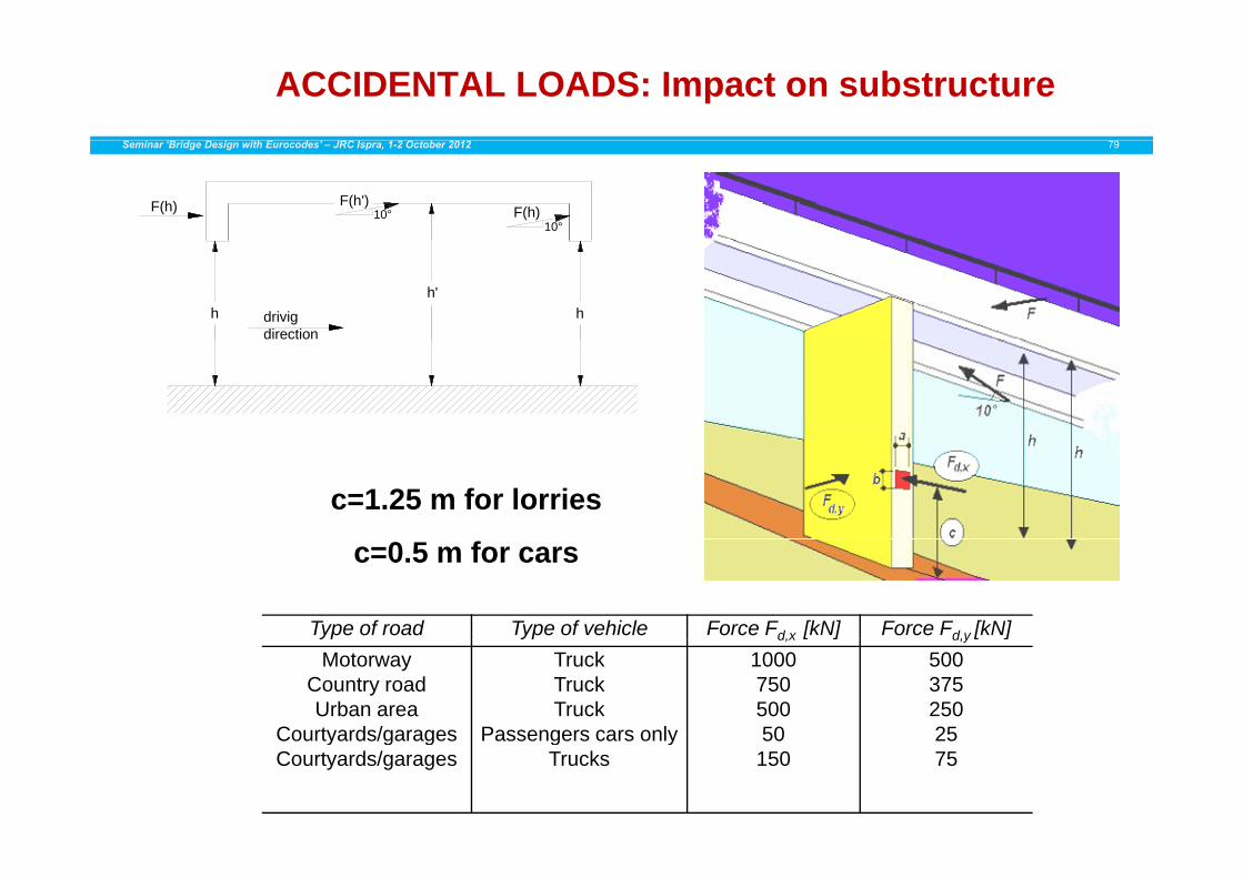
ACCIDENTAL LOADS: Impact on substructureSeminar ‘Bridge Design with Eurocodes’ – JRC Ispra, 1-2 October 2012 79
F(h)10°
F(h')10°F(h)
hh'
hdrivigdirection
c=1.25 m for lorries
c=0.5 m for cars
Type of road Type of vehicle Force Fd x [kN] Force Fd y [kN]yp yp d,x [ ] d,y [ ]Motorway
Country roadUrban area
Courtyards/garages
TruckTruckTruck
Passengers cars only
100075050050
50037525025Courtyards/garages
Courtyards/garagesPassengers cars only
Trucks50
1502575

ACCIDENTAL LOADS: Impact on substructureSeminar ‘Bridge Design with Eurocodes’ – JRC Ispra, 1-2 October 2012 80
t t
d d
structure
meanvalue
standard deviation
m mass 20 ton 12 tonv velocity 80 km/hr 10 km/hr
road
structure
d
kF
v velocity 80 km/hr 10 km/hrk equivalent stiffness 300 kN/m
Statistical parameters for input values
m=32 ton, v= 90 km/hr=25 m/s
road
v0
s
d
road
road structure mkvF r m 32 ton, v 90 km/hr 25 m/sF = 25 (300 32)0.5 = 2400 kN
vr = (v02– 2 a s )0.5 if a=4 m/s2 s=80 m15° d 20
structure=15° d=20 m
F = Fo bdd /1 (for d < db).
Type of road Type of vehicle Force F [kN] Force F [kN]
Situation sketch for impact by vehicles (top view and cross sections for upward slope, flat terrain and downward slope)
Type of road Type of vehicle Force Fd,x [kN] Force Fd,y [kN]Motorway
Country roadUrban area
Courtyards/garages
TruckTruckTruck
Passengers cars only
100075050050
50037525025Courtyards/garages
Courtyards/garagesPassengers cars only
Trucks50
1502575
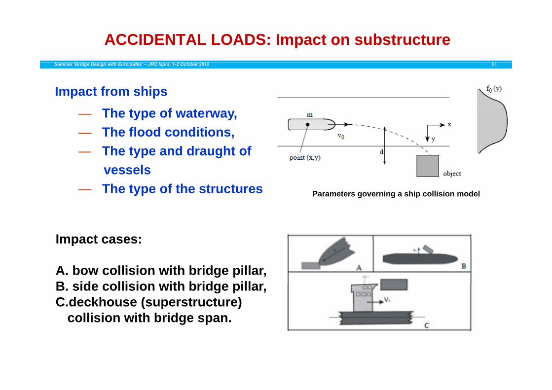
ACCIDENTAL LOADS: Impact on substructureSeminar ‘Bridge Design with Eurocodes’ – JRC Ispra, 1-2 October 2012 81
Impact from ships— The type of waterway, — The flood conditions, — The type and draught of— The type and draught of
vessels— The type of the structures Parameters governing a ship collision modelyp Parameters governing a ship collision model
Impact cases:Impact cases:
A. bow collision with bridge pillar,B id lli i ith b id illB. side collision with bridge pillar,C.deckhouse (superstructure)
collision with bridge span.

ACCIDENTAL LOADS: Impact on substructureSeminar ‘Bridge Design with Eurocodes’ – JRC Ispra, 1-2 October 2012 82
m [t ]
v [ / ]
k [MN/ ]
Fd[MN] F [MN]
Fd[MN][ton] [m/s] [MN/m] [MN] Fd [MN] [MN]
Table 4.5 of EN 1991-1-7
eq (C.1) of EN 1991-1-7
eq (C.9) of EN 1991-1-7
300 3 5 2 4 51250 3 5 5 8 74500 3 5 10 14 9
20000 3 5 20 30 18
Design forces Fd for inland shipsDesign forces Fd for inland ships
m[ton] v [m/s] k [MN/m]
Fd[MN]
Fd[MN]
Fd[MN]
Table 4.6 of EN 1991-1-7
eq(C.1) of EN 1991-1-7
eq (C.11) of EN 1991-1-7
3000 5 15 50 34 3310000 5 30 80 87 8440000 5 45 240 212 23840000 5 45 240 212 238
100000 5 60 460 387 460
Design forces Fd for seagoing vesselsg d g g

EN 1991-2 - Traffic loads on bridgesSeminar ‘Bridge Design with Eurocodes’ – JRC Ispra, 1-2 October 2012 83
Load models for footbridges
•LOAD MODEL Nr.1Uniformly distributed load qfk
•LOAD MODEL Nr.2Concentrated load Qfwk
(10 kN recommended)
•LOAD MODEL Nr.3Service vehicle Qserv

Load models for footbridgesSeminar ‘Bridge Design with Eurocodes’ – JRC Ispra, 1-2 October 2012 84
Recommended characteristic value for :footways and cycle tracks on road bridges- footways and cycle tracks on road bridges,
- short or medium span length footbridges :2
Recommended expression for long span length
2fk kN/m0,5q
footbridges :
2kN/12002 2fk kN/m
300,2
Lq
2 2
L is the loaded length [m]
2fk kN/m5,2q 2
fk kN/m0,5q
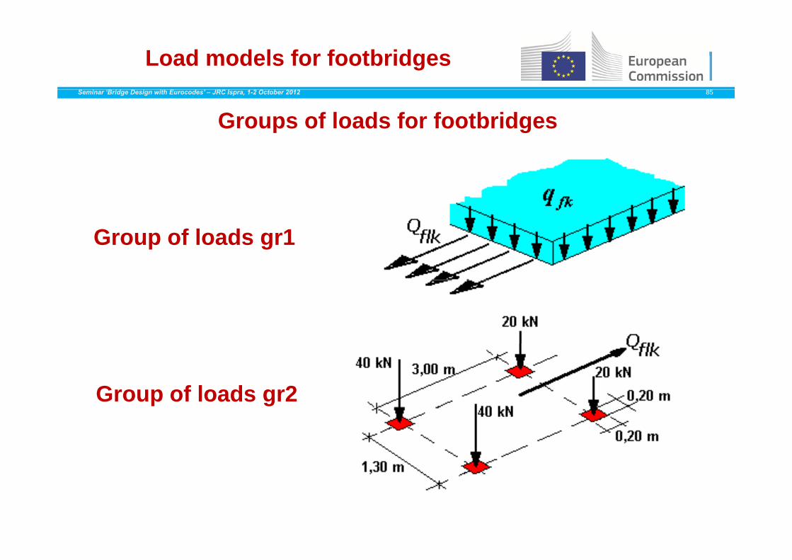
Load models for footbridgesSeminar ‘Bridge Design with Eurocodes’ – JRC Ispra, 1-2 October 2012 85
Groups of loads for footbridges
Group of loads gr1
Group of loads gr2
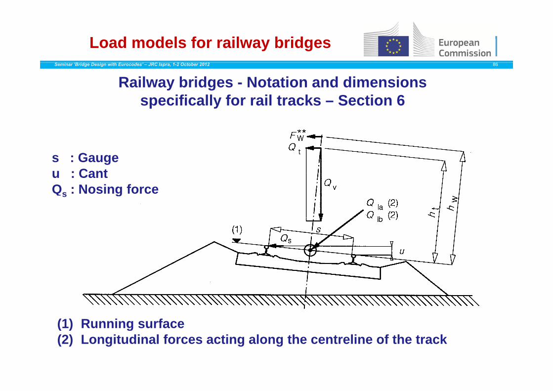
Load models for railway bridgesSeminar ‘Bridge Design with Eurocodes’ – JRC Ispra, 1-2 October 2012 86
Railway bridges - Notation and dimensions specifically for rail tracks – Section 6p y
s : Gaugeu : CantQs : Nosing forces g
(1) Running surface( ) g(2) Longitudinal forces acting along the centreline of the track

Load models for railway bridgesSeminar ‘Bridge Design with Eurocodes’ – JRC Ispra, 1-2 October 2012 87
Load Model LM 71Load Model LM 71
The characteristic values may be adjusted to the expected traffic on the bridge by a multiplication factor which shall be one of the following :0,75 - 0,83 - 0,91 - 1,00 - 1,10 - 1,21 - 1,33 – 1,461,33 is the recommended value for important and international lines.When selected, the same factor shall be applied to the other rail e se ected, t e sa e acto s a be app ed to t e ot e atraffic action components, in particular to centrifugal forces, nosingforces, and acceleration and braking.
Load models for railway bridgesSeminar ‘Bridge Design with Eurocodes’ – JRC Ispra, 1-2 October 2012 88
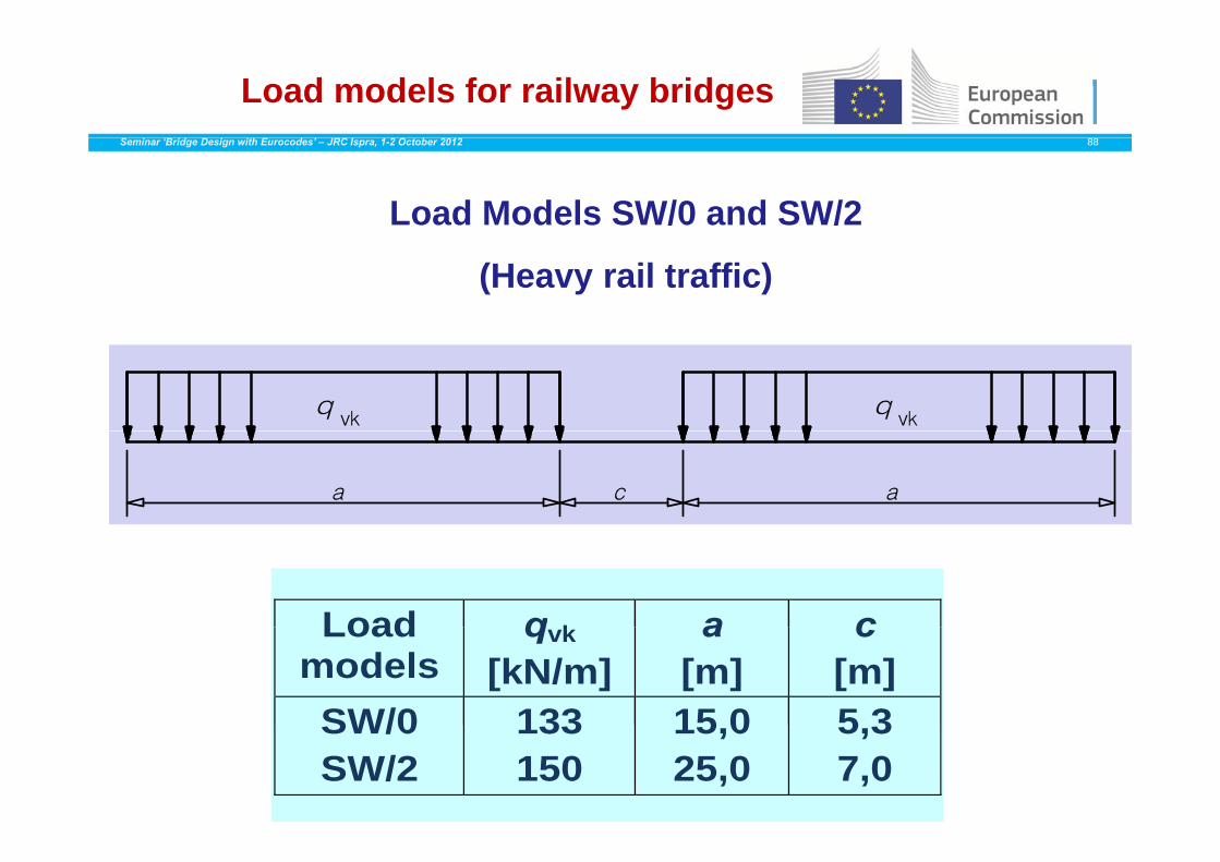
Load Models SW/0 and SW/2
(Heavy rail traffic)
Load q k a cLoad models
qvk
[kN/m] a
[m] c
[m] SW/0 133 15 0 5 3SW/0SW/2
133150
15,025,0
5,37,0

Load models for railway bridgesSeminar ‘Bridge Design with Eurocodes’ – JRC Ispra, 1-2 October 2012 89
Models HSLM-A et HSLM-B for international
high speed lines
Load models for railway bridgesSeminar ‘Bridge Design with Eurocodes’ – JRC Ispra, 1-2 October 2012 90
Dynamic effectsStresses and strains in a bridge deck due to rail traffic (including the associated acceleration) are amplified or reduced by the followingphenomena :p
- Loading celerity due to the speed of rail traffic crossing the bridge and the bridge inertia,and the bridge inertia,
- Successive loads crossing the bridge with more or less regularspacings which can excite the structure and in some cases lead tospacings, which can excite the structure and, in some cases, lead to resonance,
Variations of wheel loads due to imperfection of tracks or of the- Variations of wheel loads due to imperfection of tracks or of the vehicle (including wheel irregularities).
T h ff EN 1991 2 d fi 3 d i lifi iTo cover these effects, EN 1991-2 defines 3 dynamic amplification factors

Load models for railway bridgesSeminar ‘Bridge Design with Eurocodes’ – JRC Ispra, 1-2 October 2012 91
MaximumMaximum permissiblepermissible verticalvertical deflectiondeflection forfor railwayrailway bridgesbridges withwith 33 orormoremore successivesuccessive simplysimply supportedsupported spansspans correspondingcorresponding toto aap yp y pppp pp p gp gpermissiblepermissible verticalvertical accelerationacceleration ofof bbvv == 11 m/s²m/s² inin aa coachcoach forfor speedspeed VV[km/h][km/h]
91
N. MalakatasChairman
CEN/TC250/SC1Seminar ‘Bridge Design with Eurocodes’ – JRC Ispra, 1-2 October 2012 92
THANK YOU FOR YOUR ATTENTIONTHANK YOU FOR YOUR ATTENTION