Embed Size (px)
Citation preview

Semi-Custom Design Flow:Leveraging Place and Route Tools
in Custom Circuit Design
Nadeem Eleyan [email protected]
Ken Lin [email protected]
Masud Kamal [email protected]
Baker Mohammad [email protected]
Paul Bassett [email protected]

2
Outline
Motivation for semi-custom
Flow overview
Usage model
Better visibility
Flow details
Examples
Conclusion

3
Introduction
IC designers have two options to implement a circuit block:
Synthesis / Auto place and route (ASIC)
Custom circuit design / Custom Layout (Full Custom)
Choice is based on the following:
Design complexity
Timing requirements
Area requirements
Power requirements
Project Schedule and Resources
Problem: designers tend to think of a hard boundary between the two flows:
Block containing some non-static circuits (SRAM or dynamic) end up as Full Custom
In reality only a portion of that block is non-static
Most blocks also contain some standard CMOS circuits (data path and control logic)
These portions can be built as ASIC or tiled standard cells.
Goal: allow designers to mix and match aspect from both ASIC and Full Custom approaches to improve productivity
4
Full-Custom vs. Semi-Custom vs. ASIC

5
Semi-Custom flow overview
The Semi-Custom block partitioning:
True Custom Macro Sub-block:
Smallest portion of design that has to be Full Custom
Ex: SRAM array with non-static, small swing circuits
Primary interface to sub-block is fully static
Soft Macro Wrapper:
Place and Route unit using standard Place and Route flow
Uses custom pitch matching, tiling and off grid pre-routing
Different portions of design handled in different ways:
SRAM and non-static periphery still Full Custom
Non-critical logic handled as standard ASIC
Timing critical data-paths tiled and pitch-matched to SRAM

6
Semi-Custom flow usage model
Problem: Full Custom design has long iteration time and upfront planning:
Circuit designer has to plan every single detail of the block
Mask designer has to draw every polygon of the layout before we can have fully routed design
Semi-custom flow uses an iterative approach:
First pass:
Create a simple floor plan
Only pre-place True Custom Sub-Blocks
Let the standard place and route tool finish off the design
First pass normally yields bad timing and routing results, but is used as a reference point
Next Iteration:
Tile and/or pre-route top critical portions of the design
Don’t have to address all the critical paths at once
Since iteration time is short (few hours) we can have a fully routed first pass design very quickly
Keep iterating until acceptable results are reached
At any point during this process we can stop and have a fully routed design
Result: better trade off between ‘how much to optimize’ vs. ‘how quick to finish’
Extreme usage case:
Manually size and pre-place each cell in the design
Pre-route each net.
Both results and effort will be comparable to a Full Custom Block.

7
Better Visibility
Top level analysis flows (Timing / Power / Noise) have more visibility into Semi-Custom Blocks
Top level:
Uses gate level tools (PrimeTime, BlastFusion, Talus, RedHawk)
Full Custom Blocks:
Block level analyzed with transistor level tools (HSpice, HSim , Nanotime, Totum)
Black box Timing / Noise / Power / Physical Abstract
Black boxing can cause miscommunication and inaccuracies
Semi-Custom blocks allow top level visibility down to standard cells and custom sub-block
Abstraction still needed for True Custom Macro Sub block
That portion of design is much smaller and can be analyzed more easily

8
Semi-Custom flow details
Semi-Custom flow is an Auto Place & Route flow with additional hooks:
Force-Keep cells and nets
Custom tiling
Custom pre-routing
Special netlist requirements:
Cells to be tiled must have predictable names
Nets to be pre-routed must have predictable names
Synthesis flows do not guarantee these conditions
Methods to create the netlist:
RTL macros expand to predetermined gate level structures
Write netlist manually by hand or script
Schematic entry using standard cells
We chose the schematic entry method because our designers were more comfortable with it

9
Semi-Custom flow details (cont.)
Force-Keep Cells & Nets:
Default behavior of standard Place and Route flows is to optimize any gate or net in the design
Problem: tiling scripts may fail if instances disappear or change
Same is true for nets we intend to pre-route if the flow inserts buffers in them
Solution: mark cells to be tiled and nets to be pre-routed with “Force Keep”
This ensures that they are still in the netlist when we reach the tiling and routing stages
This however does not prevent the flow from upsizing / downsizing the gates as need

10
Semi-Custom flow details (cont.)
Custom Tiling:
Tile critical parts of design
Use different algorithms depending on the context
Ex: Tile cells in reference to a custom sub block’s pins
Diagram shows typical pitch matching/tiling example:
Left side has Memory array with non-standard pitch
Tile next stage of logic to minimizes vertical routing
Place each cell in the same row as the custom pin it needs to be routed to
Might end up with collisions:
Both Inv<0> and Inv<1> need to be in second row
Use collision detections code to legalizes locations

11
Semi-Custom flow details (cont.)
Custom Pre-Routing:
Pre-route critical nets in the design
Standard auto router is timing driven:
Tends to give certain bits of a regular structure higher priority than others
This results in non-uniform routing and congestion
Pre-routing ensure uniformity and congestion relief
Pre-routing also used to guide router through off-grid routing resource in sub-arrays:
net<0:3> needs to be routed through the sub-array
Each bit has only one metal 4 off-grid open track available
Pre-route metal 4 wires over the sub-array
Run standard router to finish off the route

12
Semi-Custom Examples
Semi-Custom flow successfully use in Qualcomm high performance DSP core in 45nm technology
The two areas the flow was used:
Memory blocks tiling
Pure data-path tiling
Memory block tiling example:
4 K Bit, 6 Read, 4 Write multi-port register file.
four 1K Full Custom sub arrays
Tiled first stage muxing between sub-arrays
Pre-routed mux outputs through sub-arrays
Tiled design

13
Semi-Custom Examples / Register file
Pre-routed design Fully placed and routed design

14
Semi-Custom Examples / Register file (cont.)
The goal of the tiling and pre-routing in this case was to guide the Auto Place & Route flow out of the congested region between the sub arrays.
Congestion map w/o tiling Congestion map with tiling

15
Semi-Custom Examples / Register file (cont.)
Table shows the following three cases:
No custom tiling or pre-routing (ASIC case)
With custom tiling only
With both custom tiling and pre-routing
no tiling or
pre-routing
with tiling only with tiling & pre-routing
Total cell count 10120 10923 10910
Total cell area 0.042 mm2 0.039 mm2 0.038 mm2
Total wire count 140946 174025 139375
Total wire length 0.92459 m 1.01119 m 0.80323 m
Cells tiled 0 (0%) 1536 (14%) 1536 (14%)
Wires pre-routed 0 (0%) 0 (0%) 3388 (3%)
Short/Open/DRC 339/42/135 0/0/0 0/0/0
Note: only 14% of cells tiled
Note: only 3% of wires pre-routed
Tiling alone helped reduce the total cell area and eliminate shorts, opens and DRC
However, tiling alone increased the total wire count and length
Router can not utilize off-grid routing tracks in sub-array
Ends up routing around sub-array
Pre-routing critical nets through the non-standard pitch open tracks was needed

16
Semi-Custom Examples / Pure Data-Path example
Pure Data-Path block tiling example:
32 bit data path consisting of 6 stages of 2:1 muxs
Block was implemented first as pure ASIC
Block was rebuilt using custom tiling to align each data path bit in straight line
In ASIC case BlastFusion optimized the circuit using different types of cells
ASIC case tiling and routing Semi-Custom case tiling and routing

17
Semi-Custom Examples / Pure Data-Path example (cont.)
Table shows the two cases:
Full ASIC and
Tiled data-path
Note: cell count went down by 70% as result of custom tiling
ASIC case has high utilization which cases worse placement and routing
Tiling reduced utilization by 34%
Tiling also resulted in cleaner routing
No custom pre-routing was needed
no tiling with tiling % smaller
Total cell count 842 247 70.6%
Total cell area 0.001763 mm2 0.001161 mm2 34.1%
Utilization 89.3% 58.5% 34.5%
Total wire count 6558 2650 59.6%
Total wire length 0.00930 m 0.00523 m 43.7%
Cells tiled 0 (0%) 196 (77%) -
Wires pre-routed 0 (0%) 0 (0%) -
Short/Open/DRC 0/0/0 0/0/0 -
18
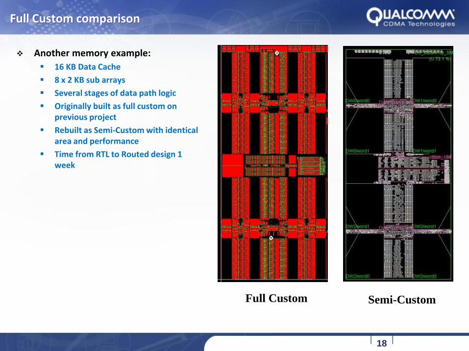
Full Custom comparison
Another memory example:
16 KB Data Cache
8 x 2 KB sub arrays
Several stages of data path logic
Originally built as full custom on previous project
Rebuilt as Semi-Custom with identical area and performance
Time from RTL to Routed design 1 week
Full Custom Semi-Custom

19
Full Custom comparison (cont.)
Fully routed
Semi-CustomMetal 4 routes Metal 5 routes
20
Conclusion
Semi-Custom flow is a powerful design tool:
Improves custom circuit designers’ productivity
Allows control over custom placement and routing
Encourages designers to focus on critical parts of the design
Utilizes standard Place and Route tools for non-critical parts of design


![Augmenting Static Visualizations with PapARVis Designer · mar [18], leveraging its simplicity and expressiveness to spec-ify 2D visualizations.PapARVis Designer enables designers](https://img.dokumen.tips/doc/110x75/5f282968de10112bf8053bb5/augmenting-static-visualizations-with-paparvis-designer-mar-18-leveraging-its.jpg)