Embed Size (px)
Citation preview
NASA CR-121244J
SELF-HEALING FUSE DEVELOPMENT
by
N. D. Jones, R. E. Kinsinger and L. P. Harris
GENERAL ELECTRIC COMPANY
prepared for
NATIONAL AERONAUTICS AND SPACE ADMINISTRATIONReproduced by
NATIONAL TECHNICALINFORMATION SERVICEUS Department of Commerce
Springfield, VA. 22151
NASA Lewis Research Center ae1
Contract NAS3-14388G. R. Sundberg, Project Manager T j 1g2)
(NASA-CR-121244) SELF-HEALING FUSEDEVELOPMENT Final Report (GeneralElectric Co.) CSCL 09A
N73-3019
UnclasG3/09 12778
https://ntrs.nasa.gov/search.jsp?R=19730021459 2018-08-30T13:48:24+00:00Z

NOTICE
This report was prepared as an account of Government-sponsoredwork. Neither the United States, nor the National Aeronauticsand Space Administration (NASA), nor any person acting onbehalf of NASA:
A.) Makes any warranty or representation, expressed orimplied, with respect to the accuracy, completeness,or usefulness of the information contained in thisreport, or that the use of any information, apparatus,method, or process disclosed in this report may notinfringe privately-owned rights; or
B.) Assumes any liabilities with respect to the use of,or for damages resulting from the use of, any infor-mation, apparatus, method or process disclosed inthis report.
As used above, 'person acting on behalf of NASA" includesany employee or contractor of NASA, or employee of such con-tractor, to the extent that such employee or contractor of NASAor employee of such contractor prepares, disseminates, orprovides access to any information pursuant to his employmentor contract with NASA, or his employment with such contractor.
Requests for copies of this report should be referred to
National Aeronautics and Space AdministrationScientific and Technical Information FacilityP.O. Box 33College Park, Md. 20740
FINAL REPORT
SELF-HEALING FUSE DEVELOPMENT
by
N. D. Jones, R. E. Kinsinger and L. P. Harris
GENERAL ELECTRIC COMPANYTube Products DepartmentMicrowave Tube Operation
Schenectady, New York
prepared for
NATIONAL AERONAUTICS AND SPACE ADMINISTRATION
January 30, 1973
CONTRACT NAS3-14388
NASA Lewis Research Center
Cleveland, OhioG. R. Sundberg, Project Manager
I

PRECEDING PAGE BLANK NOT FILMFD
FORE WORD
The work described herein was performed by the General ElectricMicrowave Tube Operation under NASA Contract NAS3-14388 with N. D. Jonesas the principal investigator. G. R. Sundberg, NASA-Lewis Research Centerwas Project Manager.
iii
PRECEDING PAGE BLANK NOT FILMSID
TABLE OF CONTENTS
Page
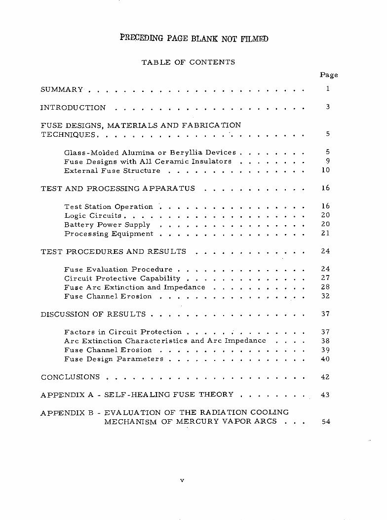
. . . . . . 1SUMMARY . . . . . . . . . . . . . . . . .
INTRODUCTION . . . . . . . . . . .
FUSE DESIGNS, MATERIALS AND FABRICATIONTECHNIQUES . . . . . . . . . . . . . . .
Glass-Molded Alumina or Beryllia Devices ........ 5Fuse Designs with All Ceramic Insulators . . . . . . . . 9External Fuse Structure . . ............ 10
TEST AND PROCESSING APPARATUS
Test Station Operation ......Logic Circuits . .........Battery Power Supply .....Processing Equipment ......
TEST PROCEDURES AND RESULTS . .
Fuse Evaluation Procedure ....
Circuit Protective Capability . . .Fuse Arc Extinction and ImpedanceFuse Channel Erosion ......
DISCUSSION OF RESULTS . . . . . .
Factors in Circuit Protection ........ .Arc Extinction Characteristics and Arc ImpedanceFuse Channel Erosion ........... . .Fuse Design Parameters ............
CONCLUSIONS .
APPENDIX A - SELF-HEALING FUSE THEORY ......
APPENDIX B - EVALUATION OF THE RADIATION COOLINGMECHANISM OF MERCURY VAPOR ARCS
v
3
5
16
16202021
. . . . . . . . . . . ...24
. . . . . . . . . . . ...24
. . . . . . . . . . . . ..27
. . . . . . . . . . . . ..28
. . . . . . . . . . . ...32
37
37383940
42
43
54
. . . . . . .
. . . . . . .
. . . . . . .
. . . . . . . : :
I I
O
0 : :

PRECEDING PAGE BLANK NOT FILMD
ABSTRACT
The mercury-filled self-healing fuses developed for this programafford very good protection from circuit faults with rapid reclosure. Fuseperformance and design parameters have been characterized. Life testsindicate a capability of 500 fuse operations. Fuse ratings are 150 volts at5, 15, 25 and 50 circuit amperes. A series of sample fuses using aluminaand beryllia insulation have been furnished to NASA for circuit evaluation.
vii

SUMMARY
The purpose of this program was to design, fabricate, test and evalu-ate mercury-filled self-healing fuses. The nominal fuse ratings were 5, 15,25 and 50 amperes at 150 dc circuit volts. Fuses should tolerate 600 voltsurges and be capable of 1000 or more operations.
Earlier work on these devices had shown that the fuse action occursin three stages: (1) an energy limiting stage defined by the energy requiredto heat the liquid mercury to its boiling temperature, causing the channelto fill with mercury vapor and break down to a mercury arc discharge; (2)a transition stage where voltage rises rapidly to a high peak value whilecurrent decays and explosive forces expel all liquid mercury from the fusechannel; (3) an arc stage when the mercury arc persists for times of theorder of 10-5 to 10 - 2 second with an arc impedance 100 or more timesgreater than the resistance of the liquid mercury column.
Two factors are important to the selection of materials and designsfor these devices: (1) the device must withstand the explosive transitionforces and (2) the fuse channel materials must withstand a very large fluxof heat energy dissipated while the fuse arc persists. Alumina andberyllia ceramics were selected as fuse channel materials for this work.
External metal rings were designed to pre-compress the ceramics, thuspreventing the ceramic from being damaged by the explosive transitionforces. Fuses using channel diameters ranging from 0. 15 to 1.2 mm werefabricated and tested. Larger channel fuses had only one channel, whilethe smaller channel devices had up to twelve. The smaller diameterchannels using extruded ceramic tubing molded in glass presented formi-dable problems in fuse fabrication. However, the larger channel devicesare machined from solid alumina and fewer fabrication problems are en-countered. Fuses of both designs have been furnished to NASA for furtherevaluation.
A simple bellows, heavily spring-loaded and mechanically restrained toresist impact forces, adequately provides the elastic characteristics requiredof the fuse container. These devices are sealed off by means of a noveltechnique utilizing silicone rubber.
A fuse test station with an SCR-switched test circuit was designed
and fabricated for testing these devices. Fuse tests under a variety ofsimulated fault conditions can be accomplished with this versatile circuit.
A standardized set of test procedures was established to evaluateand compare the performance of the various fuses tested. Three majorfuse characteristics were evaluated: circuit protective capability, fusearc extinction and impedance, and fuse channel erosion.
This program has provided a better understanding of the extinctioncharacteristics and the impedance of confined metal-vapor arcs througha combination of theoretical analysis and experimental evaluation. Goodagreement was obtained between analysis and test-data. Results showthat faster switching action and higher arc impedance are characteristicof smaller diameter fuse channels. This characteristic high arc imped-ance coupled with the fast-switching capability of the self-healing fuseprovide excellent circuit protection. In addition these factors will permitthe use of lighter auxiliary switching devices in the protected circuit.
The explosive mechanical forces created during fuse operation werecontained by structures embodying all-ceramic insulators, pre-stressedby force-fitted external metal rings. Fuses with a simpler ceramic con-figuration molded in glass were less durable. Life tests indicate capa-bility of 500 operations when the fuse channel experiences 5 kW/cm2 en-ergy for 1 millisecond or less.
Fuse design parameters are described in relation to fuse cold resist-ance, fault current limiting action, arc extinction and arc impedance.
2

INTRODUCTION
The purpose of this program was to develop, design, fabricate, testand evaluate mercury-filled self-healing fuses. These devices interrupt anelectric current under overload conditions and then automatically reestab-lish the conduction path within a time of the order of a millisecond. Thegeneral form of the fuse is a mercury-filled, closed container consistingof two end reservoirs electrically insulated but connected by a smallchannel. When excessive current flows through the channel, mercury isvaporized and the current is interrupted. The mercury conduction path isthen restored by gravity-independent forces supplied by the container.
The nominal fuse ratings sought were 5, 15, 25 and 50 amperes at150 nominal d-c circuit volts. Fuses should tolerate 600 volt surges andbe capable of 1000 or more operations without failure. The fuse is to bestorable between - 65 C and +1500°C and operable at ambient temperaturesfrom - 300°C to +80°C. This report describes the work performed towardachieving these objectives.
This program is an extension of earlier work performed under NASAcontract NAS12-675 and described in report NASA CR-72868. Backgroundalso was provided by prior art which has been documented.*
The self-healing fuse takes advantage of the large increase in elec-trical resistivity going from the liquid state to the gaseous vapor state forliquid metals. Thus, these devices have also been termed "Change ofState Current Limiters". The operation of these fuses can be describedin three stages: (1) The energy-limiting stage is defined by the energy re-quired to heat the liquid mercury in the channel to its boiling temperature.The channel cross-section is then filled very rapidly by a bubble of neutralmercury vapor, which simultaneously breaks downtoa mercury arc dis-charge. (2) In the transition stage, the fuse voltage initially rises very ra-pidly to a value determined by the circuit parameters, while current simul-taneously decays at a rate determined by these parameters. During thetransition stage explosive forces expel all the liquid mercury from the chan-nel. (3) After the transition, the mercury arc either extinguishes or per-sists fortimes of the order of milliseconds with an arc impedance of 100 ormore times greater than the resistance of the liquid mercury column.
*L. J. Golberg, patent No. 3, 273,018; R. L. Hurtle, patent Nos. 3,117,203and 3,158,786; L. P. Harris, patent No. 3, 389,359; J. J. Keenan, patentNo. 3,389,360
3

The explosive transition forces per unit area are high -- generatingpressures of the order of 10, 000 psi -- although the resulting net force
is quite small due to the very small channel size. Similarly, the currentlimiting arc results in a large flux of heat energy per unit area for the
fuse channel walls, although the circuit energy is limited to very modest
levels by the high arc impedance. Since the transition occurs in a very
short time and most of the transition energy becomes heat at the walls of
the fuse channel, transition stage heat energy also becomes an important
factor.
4

FUSE DESIGNS, MATERIALS AND FABRICATION TECHNIQUES
In terms of technology, the background available from the earlier workcited in the "Introduction" had established the existence of two major factors
as governing the usefulness of these devices: (1) the device must mechani-cally withstand the explosive transition forces, and (2) the fuse materialsmust withstand the large flux of heat energy generated within the fuse chan-nel during the transition explosion and any subsequent current-limiting arc
action. Thus these two factors become primary considerations in selection
of materials and designs for these devices. Because some practicable limitshad to be established relative to the variations of materials and designs thatcould be evaluated, and since the availability and fabrication techniques favor-ed the use of alumina or beryllia as an insulator, these two materials wereestablished as the major candidates.
GLASS-MOLDED ALUMINA OR BERYLLIA DEVICES
Because analytical studies of the high-pressure metal vapor plasmahad indicated some advantage for fuse channels with diameters of 0.2 mm orless (refer to Appendix A), work effort during the early phases of this pro-gram were directed to small diameter, multi-channel devices. These devicesutilized commercially available two- and seven-hole 99 percent pure aluminaand two-hole beryllia tubing.
The tubing was molded in glass having a coefficient of expansion similarto alumina and beryllia. Two design variations of these glass-molded fuses
are shown in cross-section in Figures 1 and 2. The external rings in eachdesign are nickel alloy with a thermal expansion slightly higher than glass orceramic. Thus, the metal rings pre-compress the glass and ceramic as theassembly cools down after molding the glass in place. This pre-compression
prevents the ceramic from being fractured by the tensile stresses induced bythe explosive transition forces.
Several devices were fabricated using these fuse designs, but perform-
ance was inconsistent. X-ray examination showed that small voids (bubbles)had formed in the glass during the molding process, causing fractures in theglass and ceramic tubing. Mercury was filling the voids thus creating someelectrical shorting of the fuse channels.
Fewer voids occurred in fuses of the glass-molded design shown in
Figure 3; however, these voids were less likely to cause electrical shorting
5

PINCHOFF
?.-GLASS
L.~~~~~S - ~~RESTRAININGRING
~~~~~NT BELLOWS
HEAVY SPRING
Figure 1 - Glass-Molded Fuse Design
6

-SIX-HOLEALUMINA
WELDPREP
Figure 2 - Glass-Molded Fuse Configuration
7

NICKEL / ALUMINAALLOY TUBING
TWO-HOLE GLASSBERYLLIA
1 5°TAPER
Figure 3 - Glass-Molded Tapered Fuse Design
8

because the alumina tubing utilized in this design served to insulate the ex-ternal metal rings. Performance of these devices generally was superiorto those of the Figures 1 and 2 design.
The pre-compression of the glass-molded assembly is achieved byforcing accurately fitted metal rings over the machine-tapered exterior ofthe alumina tubing. The design stresses the metal to its yield strength andthe thermal expansions of metal and ceramic are an approximate match overthe operating range.
The glass-molding technique used was relatively simple. Fuse partswere placed ina graphite fixture and heated in an air oven at 950 to 1'0000°Cfor approximately 10 minutes. Moderate pressure was applied by a weightor spring to force the glass into the fuse structure. Since the glass wasalways under compression and not subject to stress failure, heat treatmentfor reducing stresses was unnecessary.
A more critical fabrication technique was to prevent glass from fill-ing holes in the inner ceramic tubing. Graphite rods or copper wires wereplaced in the ends of holes having a diameter larger than 0. 3 mm. Thesewere readily removed after the excess glass was machined off. Oversizegraphite rods were forced into the holes and later drilled out. Copper wiresslightly smaller than the holes were cemented in place with a slurry of iso-butyl methacrylate binder and boron nitride powder and later the copper wasetched out with hot aqua regia. The boron nitride strongly inhibits glassfrom entering the holes.
Smaller holes (0. 15 to 0. 3 mm in diameter) could be kept open withthe copper wire technique, but graphite rods that small were unobtainable.A graphite cap was placed over each end of the small alumina tubing whichextended beyond the outer alumina tubing. After the glass molding processwas completed, the excess length of small tubing was machined off. Becauseof the toxicity of beryllia, machining could not be performed in the MTO shop,and as a result only the copper wire technique could be applied to the smallberyllia tubing.
FUSE DESIGNS WITH ALL-CERAMIC INSULATORS
In order to fabricate fuses completely free of the voids experienced withglass-molded fuse assemblies, ceramic insulators with one, two and twelvesmall holes were fabricated of 'hLltra-pure" (99. 9 percent) alumina body'> pre-pared in General Electric's Microwave Tube Operation (MTO) Ceramic Lab-oratory.
* GE Proprietary
9

The design of the 1- or 2-hole devices is shown in Figure 4, and thefuse parts are shown pictorially in Figure 5. The pre-comrpression of thetapered ceramic member is provided by forcing three 'accurately fittedmetal rings over the ceramic, as described for the glass-molded design ofFigure 3. The use of three metal members allows narrower open spacesbetween rings and locates them near the ends of the fuse channel. Thisplaces the areas of sudden stress change, which will occur in the space be-tween rings, at a location of lesser internal stress as compared to the cen-ter of the fuse channel where internal stress is at a maximum. The three-ring design is more feasible for longer fuses with a 24-mm long ceramicmember. However, the shorter designs (Figure 3) with a ceramic 10-mmlong are mechanically less amenable to the three-ring design, but fortun-ately, internal stresses are reduced because of the shorter length andsmaller hole diameter.
Components for the all-ceramic short fuse design are photographedin Figure 6. The tapered ceramic shown has twelve 0. 17-mm diameterholes. This ceramic was a 99.9 percent pure alumina cast body' fabricatedin MTO ceramic laboratory. Two sample runs were made, but both pro-duced porous ceramic bodies. Since considerable process developmentwould have been required to produce non-porous bodies, the approach wasabandoned. One fuse was assembled and tested briefly, 'but no significantresults were obtained.
EXTERNA'L FUSE STRUCTURE
The mechanical requirements for the external fuse structure are notstringent and consequently cause little difficulty. (The large per unit forcesgenerated in the fuse channel cause only small net forces due to the verysmall area of the channel.) The fuse structure, however, must supply gravi-ty-independent restoring forces to inject mercury back into the fuse channelafter the fuse fires, and must also allow for thermal expansion and contrac-tion of the mercury. To accommodate these requirements, end buffer sectionsconsisting of a rigid cup and a spring-loaded flexible diaphragm in a cup con-figuration, as shown in Figures 4, 5, and 6 were provided on each end of thefuse.
Three completed fuses showing the heavy spring structure can be seenin Figure 7. Only one spring was provided for the shorter fuses, whichhave a smaller volume of mercury and require less flexibility of the endbuffer s.
Because the transition forces are of short duration, the impact effectsof the force are quite high, and the diaphragm structure will be distorted
10

I OR 2FUSECHANNELS
TAPEREDCERAMIC
TAPEREDMETAL RINGS
I
ARC - WELDED
RESTRAINTSTRAP
HEAVY' SPRING
Figure 4 - Design for One- or Two-Channel Devices
11
ENDVIEW
SECTIONA-A

iii!i ! ! % ! ii CERAMIC
,_-.__ii ::METALRINGS
1~::;:~%FUSECHANNEL
INSULAO
:": ; , ; BELLOWS
TUBULATIO
I CM.
Figure 5 - Component Parts for One- or Two-Channel Devices
12

METALRINGS
INSULATOR
BELLOWS
I CM.
Figure 6 - Component Parts for All-Ceramic Short Fuses
13

Figure 7 - Completed Fuses with Heavy Spring Structure
14

unless a strong restoring force is provided. This was accomplished by theheavy spring and a restraint strap which holds the spring almost fully com-pressed. The end buffer sections not only limit the impact-induced flexingof the diaphragm, but allow the diaphragm to move the required four per-cent (in volume) to provide for thermal expansion of the mercury.
A hermetic seal was provided for these fuses by a technique devel-oped in earlier fuse work under NASA contract NAS12-675. This techniqueinvolves coating the interior of the tubulation with a thin layer of siliconerubber (shown at the left in Figure 8) during fuse fabrication. When the fuseis ready for sealing-off, the tubing is flattened and folded, as seen at theright in the figure, thus effecting a hermetic seal.
RUBBER
COATEDTUBULATION
ING
.FLATTENEDAND FOLDEDOVER
AFTERSEAL-OFF
Figure 8 - Silicone Rubber Seal-Off Technique
15

TEST AND PROCESSING APPARATUS
The principal objectives for testing fuses investigated during thisprogram were: (1) realistic evaluation of their circuit protective capabil-ities, and (2) comparison of the performance of various fuse designs andmaterials. In addition, "final design"' fuses were subjected to endurancetests to evaluate fuse durability. Circuit parameters influence fuse oper-ation in important ways: i.e., circuit parameters determine fault currentrise time, the maximum fault current, and the transient overvoltage andenergy the fuse must accommodate during the transition stage. Therefore,circuit parameters were kept constant for most of the fuse tests performed.
TEST STATION OPERATION
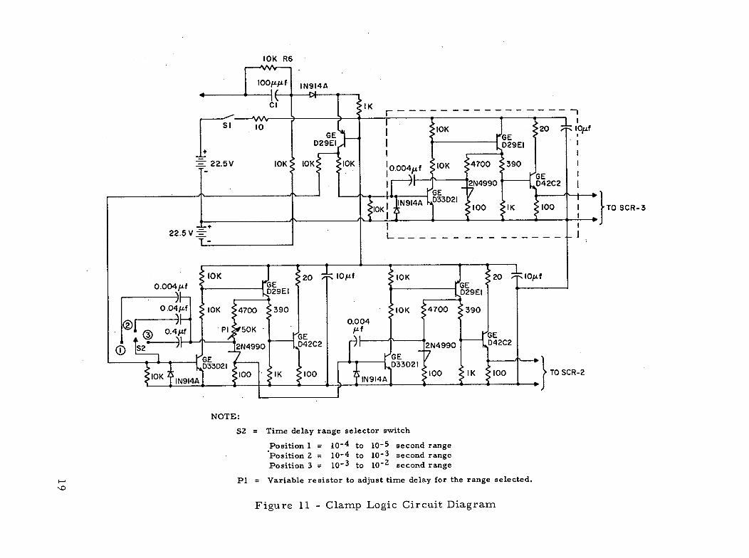
Since one principal application of such fuses would be the protectionof solid-state devices, the fuse test current was passed through siliconcontrolled rectifiers (SCR's) which also served to switch the fault currentduring testing. The test station design is represented by the circuit dia-gram shown in Figure 9. This diagram shows the complete circuit withthe exception of details for power supply switching, safety interlocks, in-strumentation and lamp load switching. The logic circuits are shown inFigures 10 and 11 and their functions are described in the following section.,
The "normal" circuit modes for fuse tests are represented by lampbank R1, rectifier SCR-4 and the fuse under test, Fl. When the normalcurrent is turned on, the bypass through fuse F4 is actuated briefly toavoid fuse Fl firing due to the high "inrush" current of lamp bank R1.
When the fuse is test-fired, the simulated "fault" current is passedthrough fuse F2, variable resistor R2, rectifier SCR-1 and thus throughfuse Fl. When fuse Fl fires, the transient overvoltage appearing acrossF1 is used as a signal to actuate the clamp logic circuit which, after asuitable time delay actuates rectifier SCR-2. This clamp circuit divertscircuit energy from fuse Fl when the fuse arc persists. If the arc ex-tinguishes, the current through SCR-1 and SCR-4 will commutate off after10 - 5 to 10 -
4 second and, therefore, no current will flow through SCR-2.The primary purpose for fuse F2 is to open the high dc fault current whenit is passed by the " clamp" circuit. Thus, the circuit breaker does notrequire the capability of opening these heavy currents, but needs only toopen the normal circuit current. Fuse F2 is selected such that it will notopen if SCR-1 and SCR-4 commutate; therefore, fuse F2 is of larger I 2 tcapacity than fuse Fl.
16

o. 5,Q o.5/fR5 C2
SCR-1, SCR-4SCR -2SCR-3D1DZD3, D11, D41
= C158E= C158PB= 2N3275= A96C= 1N4511= 1N1348
Rectifier (GE)Rectifier (GE)Rectifier (FSC)Rectifier (GE)Rectifier (GE)Rectifier (GE)
Figure 9 - Test Section Circuit Diagram
17
O.5/fC4
BYPASSFOR
LAMPTURN-ON
where:

----- _---_----_--
! IOK I 20 I
TO OSCILLOSCOPETRIGGER
Figure 10 - Start Logic Circuit Diagram
"FUSE TESTSTART"
10 MEG
TOSCR- I
IOK R6
-- I
10K J! F .20 1 I/f
'-~,....,.. LD33D2I Y 1 1 , -,OK 100 IK 100TOSCR-
GE 2D29EI 29EI1
4700 390 | 00K 4700 3900.004
2N4990 - D42C2 2N4990 D42C2
,ED33D21 . t l, Voo I~ oK Z100 100 IK 100TOSCR-2
S2 = Time delay range selector switch
Position 1 = 10-4 to 10-5 second rangePosition 2 = 10-4 to 10-3 second rangePosition 3 = 10-3 to 10-2 second range
P1 = Variable resistor to adjust time delay for the range selected.
Figure 11 - Clamp Logic Circuit Diagram
NOTE

Circuit damping, as required, is provided for all switching elementsof the circuit. Rectifiers SCR-1, SCR-2, and SCR-4 have RC "snubbers"designed to limit the current and voltage rates of rise over the contemplatedrange of inductance. Overvoltage is heavily damped for fuse F2 and the cir-cuit breaker contacts. Inverse overvoltage protective diodes are providedfor SCR-1, SCR-4, L1, L2, and the circuit breaker coil.
LOGIC CIRCUITS
The start logic and clamp logic circuits are shown in Figures 10 and11, respectively.
The start logic module supplies a " start" current pulse to actuateSCR-4 and SCR-1, when S2 and S3 are actuated, respectively. The '"FuseTest Start" circuit also supplies a trigger pulse to synchronize the oscillo-scope used to monitor the fuse operation, and provides a few microsecondsdelay in the "start" pulse so the entire fuse test may be observed on theoscilloscope.
The circuit is designed as three basic modules, plus connecting cir-cuitry and a battery power supply. A basic module is shown within thedashed lines of Figure 10. This module is a simple "one-shot flip-flop"circuit driving an output stage. The relatively large current required bythe SCR gate is supplied from a charged capacitor (10 /if).
The clamp logic module supplies current pulses to actuate the "clamp"rectifier, SCR-2, and SCR-3, which operates the circuit breaker. The"clamp" pulse is provided with a variable time delay adjustment by switchS2 and variable resistor PI as noted in Figure 11.
The same three modules are used for both logic circuits except thetime delay adjustment described above is incorporated in one module.Small batteries supply dc power for this low-drain circuit, with one bat-tery supplying additional voltage to provide a -45 volt bias which the inputsignal from the fuse must exceed in order to initiate the clamp logic. Thisprevents clamp logic initiation by the dc voltage due to fault currents pass-ing through th.e fuse "cold" resistance and viewing resistor R3. This volt-age should not exceed 30 volts.
BATTERY POWER SUPPLY
This power supply consists of fourteen 12-volt lead-acid (automotive)batteries in'series, to.provide up to 168 volts. By suitable switching,
20

12-volt steps from 0 to 168 volts are available. This supply can provideup to 1000 amperes and had a comparatively low internal inductance of
approximately 15 AgH.
The complete fuse test station is illustrated in Figure 12. The "FuseUnder Test" is enclosed in a box which would minimize mercury vapor leak-age in case of a fuse failure. The oscilloscope is used to monitor the fusecurrent and voltage.
PROCESSING EQUIPMENT
Existing vacuum equipment was adapted for use in processing thesefuses, i. e., for evacuating fuses and loading or unloading the mercury fill.The processing station depicted in Figure 13, consists of a mechanical
vacuum pump, liquid nitrogen trap, vacuum gage, glass valve, and rotat-able glass mercury-loading adapter. The glass assembly is heated by heat-
ing tape* to "outgas" the glass and to redistill mercury to obtain mercury ofvery high purity when desired (no improvement in fuse performance could
be noted when commercial triple-distilled mercury was redistilled). The
liquid nitrogen trap improves vacuum pressure as well as effectively pre-
venting mercury from contaminating the vacuum gage and pump.
'"Briskeat" No. B-2 1/2 tape, Briscoe Mfg. Company, Columbus, Ohio
21

ATICOFPANEL UNDER
TEST
BATT
SUPPL
Figure 12 - Complete Fuse Test Station
22

VACUUM
GAGE
Figure 13 - Fuse Processing Apparatus
This page is reproduced at the
back of the report by a different
reproduction method to providebetter detail.
23

TEST PROCEDURES AND RESULTS
For purposes of evaluating fuse performance and comparing variousfuse configurations, a standardized set of test procedures were establishedwith NASA concurrence. These test procedures are described below andtest results are summarized under three headings: " Circuit ProtectiveCapability", "Fuse Arc Extinction" and "Fuse Channel Erosion".
FUSE EVALUATION PROCEDURE
The first step is a determination of the fuse rated current Io . Thiscurrent is defined as the steady-state current which will cause the fuse tofire within 30 to 180 seconds. A steady current of 2 Io will cause the fuseto fire within one to five seconds, and 0.'8 I o current will not cause thefuse to fire.
The second step is a determination of the I2t capability of the fuse,where "I" is the rms current and "t" the length of time current I passesthrough the fuse. This measurement was made at currents of 5 Io, 10 Io,and 20 Io.
The rms current and time were measured from photographed oscillo-scope traces of the fuse tests. A photograph of typical oscilloscope tracesis shown at the top of Figure 14, and for more clarity, the current and volt-age traces are redrawn separately at the bottom. Three traces are record-ed - one to measure the "fault" current, one the arc current, and one thevoltage across the fuse. The upper trace in the photo records only thesmaller currents of the fuse arc state -- typically 3 to 25 amperes -- and
permits accurate measurement of arc current. The lower trace recordscurrent at a resolution typically 1/10 that of the upper trace.
The current is determined graphically by dividing the current wave-form into sinusoidal, triangular and rectangular area segments, and usingfactors of 1/1V', 1/V/ and 1 times maximum current for the respective seg-ments. The I2t "let-through" is determined from total rms current passedbefore the fuse fires, squared and multiplied by the time in seconds fromtest initiation until the fuse fires.
The third step is the determination of arc extinction threshold volt-age. This is defined as the highest fuse voltage at which the arc will self-extinguish within 10 - 3 second, at least 4 out of 5 test firings. The arcextinction is shown in Figure 14 where the arc persisted approximately0.5 x 10 - 3 second. The arc also frequently extinguishes at the end of the"transition" stage, as depicted for a typical fuse test in Figure 15.
24

(a) Photograph of Oscilloscope Traces
240
40-
200 20
2150 -- 15
ro IOX CURRENT -ARC
SO - 5
40
TRANSITION
0 10 Lo110 02 0.4 0.6 _.8 1.0
TIME-MILLISECONDS
(b) Waveforms Separately Redrawn
Figure 14 - Current and Voltage Waveforms for a TypicalFuse Test
25

I
F-
0
wC,
a,4
1cr
0
Ij
z
a-
280
240 -
200
160 -
120
80
40 TRANSITION
ARCEXTINCTION
400
2500 - 'FAULT"CURRENT
200
160 240TIME - MICROSECONDS
400
Figure 15 - Current and Voltage Waveforms IllustratingRapid Arc Extinction
26
Iv\ 80 320
The fuse voltage just before arc extinction is defined as the thresholdvoltage, and is measured from photographed oscilloscope traces. The testfor arc extinction is performed for fuse currents at 2 Io, 5 Io , 10 Io, and20 Io.
For purposes of evaluating fuse channel erosion other measurementsand calculations were made. The fuse channel diameter was determinedperiodically during all fuse tests by measuring the electrical resistance ofthe mercury in the fuse channel when the fuse current is 0.8 Io . The aver-age mercury temperature is approximately 1500 C under these conditions,so a value of resistivity of 1. 1 x 10 - 4 ohm-cm is used. The changes in re-sistance are inversely proportional to the changes in channel cross-sectionalarea, so resistance changes are plotted as depicting channel erosion.
The thermal energy to which the fuse channel is subjected is measuredfrom the photographed oscillograph traces of voltage and current. Duringthe "transition" stage, energy is dissipated at a very high rate for as longas 10 - 4 second. It is reasoned that 2/3 of the total transition energyappears as heat energy at the fuse channel walls (refer to report NASACR-73868, p. 38). When the fuse arc persists after the transition stage,all the arc energy is absorbed by the walls, and these factors are applied tothe energy dissipation calculated. Effectively, negligible energy is dissi-pated in the fuse channel before the fuse fires.
The rms current and voltage are determined as described earlier inthis section. The energy in joules dissipated for a stage of fuse test oper-ation, as depicted by the oscilloscope waveforms, then is (volts) x (amperes)x (time). This energy then can be calculated from any photographed oscillo-scope trace, or energy can be estimated reasonably well from fuse test data,if the arc extinction rate is observed. The latter is feasible because theenergy of the transition and arc stages are reasonably consistent for a givenfuse in a given circuit if circuit voltage is constant.
CIRCUIT PROTECTIVE CAPABILITY
The primary protective function of current limiting devices such asthose investigated here is to limit the energy that other circuit devices aresubjected to during circuit faults. The energy limit for solid-state or othercircuit devices due to joule heating is usually expressed as an I2t rating,which, when multiplied by device impedance, gives the actual joule heating.This applies for a fault current time range from approximately 10 - 2 to 10 - 5
second. For shorter times, time rates of change for current or voltage be-comes important, and for longer times, heat capacity and heat conduction ofthe structural members become important.
27

The average time responses (calculated and measured) of several fusecylindrical channels used for this program are shown in Figure 16. Thecalculated values assume that all I'R heat is absorbed by the heat capacityof the mercury, which appears to hold true at times of 2 x 10 - 3 second orless. For longer periods heat conduction to the channel walls becomes afactor, as illustrated in Figure 16.
The appreciable deviation from calculated values for the 0.75- and0. 070-mm channels is due, in part, to the comparatively high pressureapplied to the mercury by the heavy springs of the end buffer structure ofthe fuse (refer to "External FuseStructure" sub-section). Less mechanicalpressure is applied bythe fuse structure for smaller channel devices, there-fore, the mercury boiling temperature is lower. The calculated valuesassume a pressure of 1. 5 atmospheres.
A summary of test data on I t performance, rated current and arc ex-tinction voltage are reported in Table I. The I 2 t data, including the range,are only for tests.of less than 2 x 10 - 3 second duration.
FUSE ARC EXTINCTION AND IMPEDANCE
The earlier fuse work had indicated that small fuse channels wouldprovide much higher arc extinction voltage than larger channels. This hasbeen borne out, both in the fuse operating data shown in Table I and in fur-ther analytical work (refer to Appendix A). The trend of the recent fuseoperating data for alumina is summarized as "Present Data" in Figure 17,along with curves showing the latest analytical treatment labeled "PresentTheory". Prior experimental data from the NAS12-675 program is labeled"Alumina" and "Sapphire", and prior analytical work is represented by thebars labeled "H".
The trend of the "Present Data" arc extinction voltage, as defined forthe "Fuse Tests Procedure" sub-section, is the voltage at which 80 percentof the fuse tests indicate arc extinction. Assuming that the "Present Theory"curve represents the higher voltage at which 50 percent of the arcs wouldextinguish, the agreement between theory and experience looks very good.Based on observations made during fuse tests, the attaining of a probabilityof arc extinction higher than 80 percent would require correspondingly re-duced fuse voltage. On the other hand, allowing arc times longer than 10 3
second will tend to increase the allowable fuse voltage for a given arc ex-tinction probability.
28

TABLE I - SUMMARY OF DATA OBTAINED FOR FUSE CHANNELS
OF VARIOUS SIZES
FuseChannel
Dia. x Length(mm)
No. RatedChannels Current
(A)
ItAverage 2 Range
(A s)
ArcExtinction
(V/cm)
Fuse ColdResistance
(ohms)
0.18 x 8 8
0.20 x 9 6
0.28 x 8 4
0.35 x 4 1
0.45 x 7.5 1
0.050 x 10 1
0.70 x 25 1
0.75 x 23 1
1.2 x 25 1
0.2 x 10 2
0.75 x 23 2
15
15
15
8
10
15
18
20
35
54
40
40
40
60
5
25
35
120
160
500
2
580
25-50
30-60
50-70
3-8
15-45
25-50
90-150
90-200
400-600
1-3
500-700
130*
120
80
65
50
30*
44
36
120
45
0.052
0. 045
0. 030
0. 046
0. 045
0.050
0. 060
0.050
0. 023
0. 140
0. 026
* Beryllia channel material. Other channels are alumina
29

0.2 0.4 0.6 0
- MEASURED
-- CALCULATED
MM = HOLE DIAMETER
).8 1.0 2.0 4.0 6.0 8.0 10 20 40 60 80 100FIRING TIME - MILLISECONDS
Figure 16 - Time Response for Various Fuse Channels
200 400
w0
in
L'U

ZUU
[ 150 _ _
50 -. ,QI.I,
0.01 0.02 0.04 0.06 Q08 0.1 0.2 0.4 0.6 0.8 1.0CHANNEL DIAMETER - MM
Figure 17 - Analytical and Experimental Fuse Performance vs. Channel Size

The data obtained concerning the impedance of the "stable" arc are
somewhat elusive, due to the arc instability in the first millisecond of arc-
ing. Most fuse tests were limited to 1 ms or less, but those which were
allowed to arc for longer periods indicate somewhat more stable arc behav-ior with time. Thus the data considered representative of stable arc behav-
ior are those exhibited after 0. 3 ms or more of arcing.
The impedance ratio between the observed arc impedance and "cold"(liquid mercury) resistance conforms reasonably well to the analyticalstudy of the arc reported in Contract Report NASA-CR-72868 (p. 41). The
0. 75-mm channel fuses range from 150 to 300 in impedance ratio withapproximately 220 as the most typical ratio. The 0.2-mm channel fusesrange from 350 to 700 impedance ratio with 500 as the most typical ratio.
FUSE CHANNEL EROSION
The two factors involved in enlarging or eroding the fuse channel are,thermal energy which melts or vaporizes material from the channel walls,
and mechanical shock which causes the insulating material to crack or chip.Thermal erosion is a more important factor for devices that are to with-
stand 1000 operations (the desired objective). Therefore, these deviceswere intentionally over-designed, mechanically, to minimize damage causedby mechanical shock. However, fuses fabricated by glass molding techniquesusually experienced some mechanical damage to the fuse channel. The all-ceramic fuse design shown in Figure 4 did not indicate mechanical erosion ofthe channel.
The erosion behavior of a representative group of glass-molded fusesis depicted in Figure 18. As noted in the figure, two of these fuses (MT-1and MB-5) experienced visible mechanical damage. Fuses S-20 and A-22experienced a minimum of erosion, if any. The resistance change probablyrepresents cleaning "debris" from the channel. Fuse MB-7 had 250 fusetests performed, and the data indicated that major erosion was thermal, al-though some mechanical damage was visible in X-rays taken when the devicewas filled with mercury. Under similar test conditions, fuse A-7 showedmore rapid thermal erosion in comparison to fuse MB-7. This probably illus-trates the better durability of beryllia as compared to conventional alumina(99 percent pure).
The data on fuse channel erosion for the ultra-pure (99. 9 percent)alumina indicate performance comparable to beryllia. Test results for thefour fuses tested extensively are listed in Table II.
32

0I I I I I I I I I
100 200CUMULATIVE HEAT ENERGY
x
+ = SINGLE-HOLEO = SINGLE-HOLEO = MULTI-HOLEX = MULTI -HOLE
= MULTI- HOLEo = MULTI-HOLE
ALUMINA* (A-22)SAPPHIRE* (S-20)THORIA** (MT-I)BERYLLIA* (MB-7)BERYLLIA** (MB-5)ALUMINA * (MA-7 )+ FUSE CHANNEL ENLARGES DUE TO
THERMAL EROSION** FUSE CHANNEL DAMAGE IS LARGELY
MECHANICAL
300ABSORBED - JOULES
400
X
500
Figure 18 - Test Results for Self-Healing Fuses
0.05
I
o
0Uz
0.0
3
o
0
U)
0
40
0.02
0.010.01j
0
I
0
0.06I I I
- XI
:+ o-0
I I

U.)
TABLE II - ENDURANCE TEST DATA FOR ALUMINA AND BERYLLIA FUSES
ChannelDia. Length
(mm)
0. 18
0.70
0.45
0. 75
8.0
20.0
7. 5
23.0
Material
BeO
BeO
A1203
A1203
Wall Areacm 2 x 10 - 2
136.2
44. 1
10. 6
54. 2
Typical EnergyDensity**(kW/cm 2 )
5. 8
4.8
6.6
4. 1
No.Tests
250
500
500
400
ErosionStart End
(ohms)
0. 052 0. 042
0. 058 0. 056
0. 045 0. 045
0.052 0.048
*MB-7 had 8 channels. Other fuses were single-channel devices.
**For fuse tests where the arc persists for 10 - 3 seconds.
FuseNo.
MB-7*
B-I
L-16
L-28
Change(Percent)
20
4
0
8

Since the accuracy of the energy measurements may be no better than
± 20 percent, the apparent discrepancy between energy density and erosion
rate for L-16 and L-28 may be largely measurement error. The trend of
the data indicates that an energy density of 5 kW/cm 2 is the approximate
limit for beryllia or high purity alumina. The test duration for all these
tests (before the fuse voltage was "clamped") was approximately one milli-
second. Most tests for fuses MB-7 and L-28 were conducted at 120-150
circuit volts, and fuses B-1 and L-16, which exhibited much lower arc ex-
tinction threshold voltages, were tested at 50 volts.
The following data listed in Table III were obtained prior to shipment
of 24 fuses to NASA for evaluation.
35

TABLE III - FINAL TEST DATA FOR FUSES SHIPPED TO
NASA FOR EVALUATION
Fuse ChannelDia. x Length Material
mm **
1.2 x 25 A1 2 03
0.5 x 20 A1 2 03
0.7 x 20 BeO
0.7 x 25 BeO
0.75 x 20 U
0.75 x 20 U
0.75 x 20 U
0. 75 x 23 U
U
U
U
U
U
U
U
U
U
0.75 x 23 U
0.28 x 8 A1 2 03
0. 15 x 10 U
0.15x 10 U
0. 18 x 8 BeO
0.18 x 8 BeO
0.5 x 10 Sapphire
Fuse RatingAmps. Volts
35 75
20 100
18 50
18 75
20 75
20 60
20 75
20 90
40 80
20 90
40 100
20 100
20 100
20 90
40 90
20 100
20 90
20 90
5 70
5 80
5 50
5 75
5 90
15 50
NOTES: * - Denotes fuses with two channels.All other fuses have one channel.
* *- U denotes ultra-pure alumina.
1 - External fuse structure sealed with expoxy cement,considered the least reliable structure.
2 -All-welded structure, considered highly reliable.
3 - "0"-ring sealed structure, considered moderatelyreliable.
36
FuseNo.
A-22
A-23*
B-i
B-2
L-22
L-26
L-27
L-28
L-29*
L-30
L-31*
L-32
L-33
L-34
L-35*
L-36
L-37
L-38
MA-6
MA-8*
MA-9*
MB-64
MB-7*
S-20
Note s
1
1
1
1
1
1
1
2
2
2
2
2
2
2
2
2
2
2
3
3
3
3
3
1

DISCUSSION OF RESULTS
In discussing the results in this section, four major areas are treatedin the order indicated:
(1) Factors in circuit protection.(2) Arc extinction characteristics and arc impedance.(3) Erosion of the fuse channel.(4) Design parameters for self-healing fuses.
FACTORS IN CIRCUIT PROTECTION
These devices inherently provide circuit protection superior to con-ventional fuses in two respects: 1) the arc impedance is usually largeenough to limit current during the "arc state" to approximately normalcircuit current, 2) the fast-switching capability can very quickly clearshort-term minor faults (such as occasional commutation failures in SCR-operated inverter circuits) without other circuit protective devices oper-ating, and thus, will exhibit only very momentary circuit interruption. Withrespect to arc impedance, conventional fuses exhibit comparatively low imped-ance and long persistence time (the order of 10 - 2 second), although special"rectifier" fuses tend to exhibit much shorter arc persistence -- less than10
-3 second. The high impedance of the self-healing fuse arc also allows the
use of a protective switch of relatively low current interrupting capability;and, for mechanical switches, this becomes a light fast-acting switch com-pared to the heavy contactors required to open large fault currents where nofuse is used.
The I2t capability of these devices can be adjusted over a large range,
depending upon whether a multi-hole or single-hole design is used, or what"cold" resistance is feasible for the fuse. For example, eight-channelfuses with 0. 18 x 8 mm channels have the same resistance and arc extinc-tion capability as single-channel fuses with a 0. 75 x 23 mm channel, but I 2 t
is four times higher for the latter. The I 2 t can be calculated with reasonableaccuracy as I2t - 5 x 10⁶ A 2 Amp 2 seconds, where A is the hole cross-sectional area in cm 2 . This is the basis for the "calculated" lines shown inFigure 15, where the dashed lines are current and time for constant I2t.
As can be seen from the data in Table I, there is generally a 2:1 rangein I2t performance for devices of essentially the same hole diameter. Muchof this difference can be explained by the small variations in diameter, sinceI2t would vary as the fourth power of the hole diameter. The larger diameterdevices also tend to have larger I 2 t than the calculations indicate. This is
37

probably due to the much larger wall area of the channel, which is bothlarger and longer for the same current and voltage rating.
Data on I2t performance was obtained using two circuit conditions.Most test firings were performed with the fuse at an equilibrium tempera-ture with normal circuit current flowing through the fuse and with the fuseelectrical connections (standard fuse "clips") at approximately 80 0 C.Several fuses were also test fired""cold" with no circuit current flowingprior to the "fault" current. As would be expected, the I2t rating was about25 percent higher for the fuses fired "cold" as compared to "normal" con-ditions. The data shown in Tables I and II represent "normal" current con-ditions.
ARC EXTINCTION CHARACTERISTICS AND ARC IMPEDANCE
This work has established a better understanding of the confined metal-vapor arc, both as phenomena and in terms of device design parameters.Due to the erratic nature of the arc, design parameters are not precisely de-fined, but can be approximated reasonably well.
Data most representative of arc extinction behavior are shown inFigure 17 and Table I. There are some additional variations of arc ex-tinction behavior. A substantially lower arc extinction threshold voltage isexhibited by larger single-channel beryllia fuses as compared to the aluminadevices. This is shown in Table I for the 0. 70-mm diameter channel. Theeight-channel, 0. 18-mm diameter beryllia fuses were quite comparable toalumina fuses, however. The single-channel beryllia data then may be astatistical variation in the data (there were two fuses tested, Nos. B-1 andB-2).
The introduction of impurities from the fuse channel into the mercurywould probably produce more reduction in arc voltage for alumina thanberyllia, since aluminum has a first ionization potential of 6.0 versus 9.3for beryllium and 10.4 for mercury. Thus the lower arc voltage for the twosingle-channel beryllia devices is not readily explained except as a statis-tical variation. The introduction of impurities could explain the reductionof arc extinction voltage with time as fuses are life tested, however. Thisreduction occurred for three of the four fuses tested for over 250 firings(refer to Table II). Fuse L-16, which did not experience the reduction inarc extinction voltage, was tested at 48 circuit volts.for most tests, and ex-perienced no measureable fuse channel erosion. The other three fuses ex-perienced arc extinction voltage reduction of approximately 10 to 15 percent.
38

FUSE CHANNEL EROSION
The data obtained during this program indicate that, in terms of fusechannel erosion, at least 500 fuse operations are feasible for self-healingfuses designed for this work. The energy density which ultra-pure aluminaor 99 percent pure beryllia will tolerate for 1 ms is approximately 5 kW/cm(refer to Table II). The earlier fuse work indicated that sapphire (virtually100 percent pure crystalline alumina) is at least as durable as ultra-purealumina. Thus these three insulators are regarded as esentially equal indurability, as fuse channel materials.
The data obtained do not indicate limits of energy tolerance for longertimes, but the acceptable energy would logically be proportionally lowerfor longer arc persistence times. Since relays or other mechanical devicesusually require two or more milliseconds to operate, the use of these fuseswith mechanical switches would require a more conservative fuse design ora suitable voltage derating of the fuse (energy is usually a V2 function).
The discrepancy in energy density versus erosion for fuses L-16 andL-28 may reflect a non-uniform distribution of energy for the longer, high-er voltage fuse. If this holds true, some additional derating of fuses maybe required for operation at higher voltages.
Arc extinction is also a factor in fuse channel erosion, because abouthalf of the energy impinges on the fuse channel during the one millisecondarc stage for the data cited in Table II. Thus, the energy is essentially halfas great for the arc extinction case as for the arc persistence case; there-fore, voltage derating, which increases the likelihood of arc extinction, isdoubly effective in reducing the rate of fuse channel erosion.
The fault current I is also a strong factor in channel erosion becausethe energy due to a fault would. logically fall between I and 12 as a function.The reason being that energy of the "transition" stage is a product of rmsvoltage and current (refer to "Fuse Evaluation Procedure" subsection) andthe voltage is the sum of circuit voltage plus L di/dt overvoltage resultingfrom the rapid decrease in current during the transition stage. The over-voltage may be 1 to 3 times circuit voltage for a fault current of 20 Io, whileovervoltage is usually negligible for a fault current of 2 I o in a low-inductancecircuit. This is because higher current allows more energy to eject mercuryfrom the channel, producing a shorter transition andamuchhigherdi/dt forhigher current faults. The larger single-channel fuses also experience lowerdi/dt compared to smaller multi-channel fuses because the mechanical forcesact more slowly on the larger mass of mercury.
39
The circuit inductance also has some effect on the level of "transition"stage energy for a given fuse firing because of, inductive overvoltage beingproportional to circuit inductance. Added inductance was provided in thefuse test station circuit (refer to Figure 9) to allow evaluation of this factoron fuse arc extinction and fuse channel erosion. However, the limited dataobtained at higher inductance did not provide any conclusive indications ofthe effect of higher inductance in the faulted circuit.
FUSE DESIGN PARAMETERS
The best established fuse design parameter is the cold resistance forthe mercury in the fuse channel, which is simply calculated from the resis-tivity of mercury at 1500 C (1. 1 x 10 - 4 ohm-cm). The cold resistance forthe 15- to 20-ampere fuses has been approximately 0.05 ohm for the devicestested in this program, which is about twice the resistance (or circuit powerloss) of conventional "rectifier " fuses. It is advantageous fo design for highercold resistance, since this allows the use of longer channels which leads tomore reliable arc extinction and the use of larger wall areas which leads tolower fuse channel erosion.
The current rating of these fuses generally is related to the power dis-sipation (P) and wall area (Aw) of the fuse channel. This was found empiri-cally to be a function approximated by the expression: P(watts)= 100 A
w(cm ).
The watts are I2R heating, where R is the fuse channel "cold" resistance andI is approximately 1. 5 times Io, the fuse current rating; i. e., the fuse willfire after 10 to 60 seconds at a steady current of 1. 5 I o . The 100 factor isthe product of the heat transfer coefficient "h" and "AT", the temperaturedrop between the mercury and the fuse channel. "h" would be the order of0. 5 watt/cmZ/°C and "AT" approximately 2000 C to fit these conditions.
The current rating and the response of the fuse would be appreciablyaffected by the thermal impedance of the mechanical support structure ofthe fuse or electrical connections to the fuse. Such factors must be consid-ered for any eventual application of these fuses.
The arc extinction voltage parameter for various channel diameters isdepicted in Figure 17, as a function of voltage gradient in the fuse channel.There is a statistical variation of about ± 20 percent among different devicesfor data shown for arc extinction, as well as variations with the length oftime the arc is permitted to continue. These variations in voltage becomemore important as the desired reliability is increased, or of less importancefor lower reliability.
40

The exception to the arc extinction function as presented above wasthe performance of two 0.70-mm diameter single-channel beryllia fuses,that provided somewhat lower arc extinction voltage than other fuses tested.The other beryllia fuses, having 2 to 8 channels of 0. 16 to 0. 20-mm diame-ter, were comparable to alumina fuses with 0. 20-mm channels. Both sizesof beryllia were extruded two-hole tubing obtained from the same vendorwith the same material specifications (99% +pure). Since the larger diame-ter beryllia channels also exhibited somewhat lower arc impedance, it wouldappear that the behavior of these devices may represent the presence of alower ionization potential impurity in the beryllia; however, this conjecturecould not be verified within the confines of this program.
Brush-Wellman, Inc., Elmore, Ohio 45416.
41

CONCLUSIONS
Extensive self-healing fuse tests were performed in a speciallydesigned solid-state test circuit. These tests demonstrate the superiorityof these fuses in protecting solid-state devices, since they provide betterenergy-limiting action and faster current interruption than commerciallyavailable conventional fuses. Test data shows consistent performance, interms of energy-limiting action, for both single-and multi-channel con-figurations in alumina and beryllia. The available data cover the range of5 to 40 amperes; however, fuse performance can reasonably be projectedto provide protection over wider current and voltage ranges.
It has been found that explosive mechanical forces generated by fuseoperation can be contained by a fuse design embodying all-ceramic insu-lators pre-stressed by force-fitted external metal rings. Fuses utilizingsimpler ceramic configurations molded in glass were less durable. Fusesof both designs have been furnished to NASA for further evaluation.
Life tests were conducted to demonstrate a capability of at least 500operations where the energy impinging on the fuse channel was 5 kW/cm 2
for one millisecond.
The switching capability of these devices has been extensively evalu-ated and compared to an analytical treatment of mercury-vapor arcs, withgood agreement. A high arc impedance, which sharply limits the currentand energy of faulted circuits, has also been demonstrated. Smaller fusechannels provide both better switching performance and higher arc imped-ance.
A simple bellows, heavily spring-loaded and mechanically restrainedto resist impact forces, adequately provides the elastic characteristics re-quired of the fuse container. A novel technique utilizing silicone rubber wasapplied to seal off these devices.
42

APPENDIX A
SELF-HEALING FUSE THEORY
R. E. Kinsinger
In the earlier theoretical work on mercury filled self-healing fuses(see Appendix A of Contract Report NASA CR-72868), L. P. Harris hasconstructed steady state arc characteristics (field versus current densityfor fixed diameter) using a crude model. The arc energy equation, bal-ancing Joule heating against several different dissipation mechanismstreated separately has been taken into consideration.
The cooling mechanisms considered were:
(1) atomic conduction
(2) electron conduction dominated by electron-neutralcollisions
(3) electron conduction dominated by electron-ioncollisions
(4) ion diffusion
(5) radiation.
The conductivity in the channel was determined by electron-neutralcollisions for: (1), (2) and (4) and by electron-atom collisions for (3) and(5). For each case, a simple temperature profile was adopted and a"characteristic" subject to the above assumptions was generated. Thefinal characteristic for a given channel diameter was arrived at by assum-
ing that the results of (2) - (5), with qualitatively similar temperatureprofiles, could be summed in a straightforward manner. The result ofthis summation was plotted for the high temperature - high current densityregime while the result for (1) was adopted for the low temperature - low
current density regime. Since the former gives a generally positive in-cremental resistance and the latter a generally negative incremental resist-ance, there is a field of voltage minimum which is a function of the channeldiameter.
The value of characteristic curves is twofold. They can give a quali-
tative indication of the performance or failure mode of test fuses as wellas providing design information through the determination of a minimum or
43

extinction electric field, Eext' as a function of channel diameter. It wastherefore, decided to improve the theoretical determination of the arccharacteristics.
For the small channels (D < 0. 05 cm) under consideration for thedesign and testing of this study, Harris's results provide justification forthe neglect of radiation as an energy transfer mechanism. For narrowchannels the arc is optically thin, and for the temperature range under con-sideration (T < 1.2 eV) the total power radiated in the continuum is smallin comparison with that transported by conduction. It may be assumed thatin this regime line radiation may be neglected as well.
With radiation neglected, the steady arc energy balance equation forcylindrical arcs can be written
o(p, T)E2 + 1 rK(p, T) aT (1)r ar ar
where T is a local (radius dependent) temperature, E is the arc electricfield, and c((p, T) and K(p, T) are the coefficients of electric and thermalconductivity with local thermal equilibrium assumed throughout. The firstterm, yE , provides Joule heating while the second term must include theenergy transfer mechanisms (1) - (4).
The program ARC3 ( a program listing is included in this appendix)is set up to solve this differential arc cooling equation in the following way.Since for a given solution E is independent of r and T, *we define a newindependent variable.
r = rE (2)e
and write
i+ a( T) +re ar e K(T) r (3)
The boundary conditions are given as
T(r = 0)= T
T(r = R) = Tw (R ~ radius of channel) (4)
44

With these boundary conditions the program integrates the differentialequation from the center, re = 0, to the wall and determines:
R'E - radius of arc channel · electric field
Fw/E = K(Tw) r e (5)
(energy flux at channel wall/electric field)
J/E = = R RE (Fw/E) (6)
(average conductivity of channel and temperatureprofiles, T(re).)
The wall temperature may be chosen as desired. Values as widelyspaced as the boiling point of mercury (629 K) and (0.2 eV = 2321 K) pro-duce minor.changes in the results.
The center temperature is parametrically varied over a run to pro-duce results for the interesting range of current density and channel size.
Pressure is assumed uniform in the arc and is input at the beginningof the run. Pressures of one atmosphere were generally used; however,pressures as high as 10 atm made minor changes in the results.
Transport coefficients,. a(p, T) and K(p, T)are calculated in the sub-routine TRANSP. Both electron-neutral and electron-ion collisions areconsidered in determining the conductivity, o(p, T). The coefficient ofheat conduction, K(p, T) includes electron conduction, atomic conduction,and ionic diffusion components.
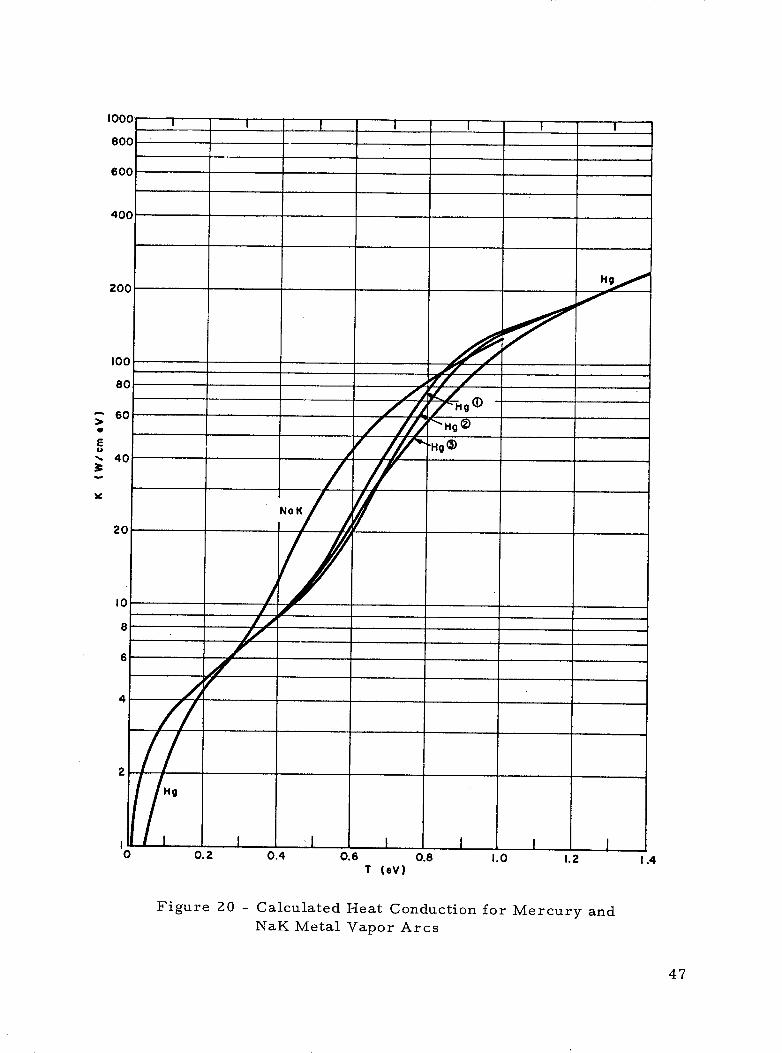
Plots of a(T) and K(T) for p = 1 atm are included as Figures 19 and20. For Hg, the cross sections for electron-atom and ion -atom momentumtransfer are somewhat in doubt; therefore, several alternatives are plotted.
-15 2 -14 2Hg (1) = 3. x 10 cm 2 Q. 1. x 10 cm
ea ia-15 2 -14 2
(2) Q = 6. x 10 cm Q. = 1. x 10 cmea la
-15 2(3) Q = 3. x 10 cm Q. = ox (no ionic diffusion)
ea ia
Plots are also included for eutectic NaK, two atoms.'of K per atom of Na.
45

80 .
60
40
20
'10 .
6
4
2
0.8
0.6
0.4
0.2
P l I ATM
0.1
0.08
0.06
0.04
0.02
0.01 I0 0.2
/0.4 0.6
T (eV)0.8 1.0 1.2
Figure 19 - Calculated Electrical Conductivity for Mercury andNaK Metal Vapor Arcs
U
0
E
b
46
1.4I m I I h I.I I , I I I I
Ij II I I
60 /TH5
- 40
20
10
8
6
4
2
0 0.2 0.4 0.6 0.8 1.0 1.2 1.4T (eV)
Figure 20 - Calculated Heat Conduction for Mercury andNaK Metal Vapor Arcs
47

The results of ARC3 are most usefully plotted as R'E vs a = J/E.Plots of this type are given for Hg (1) with T w = 629 K and eutectic NaKwith Tw = 1058 K, both at 1 atm pressure, in Figure 21. The centertemperature of the arc in eV is indicated on each plot as a parametricvariable.
By choosing a channel size R, Figure 21 could be converted to char-acteristic curves, E vs J. Since we are most interested in the extinctionfield for a given channel size, we record the minimum R E and note thatthis gives a model dependent constant for the product of channel size andextinction field. Converting to channel diameters we find:
D(cm) * Eext(V/cm)
Hg (1); p = 1 atm; T w = 629 K 3. 19 V
Hg (2) ; p = 1 atm; Tw = 629 K 3. 38 V
Hg (3) ; p = 1 atm; Tw = 629 K 3.01 V
Hg (1) ; p = 1 atm; Tw = 2321 K 3. 11 V
Hg (1) ; p = 10atm; T w = 629 K 3. 30 V
NaK ; p = 1 atm; Tw = 1058 K 2.05 V
Note that substantial changes in the electron-neutral cross section,ion-neutral cross section, wall temperature, and pressure produce minorchanges in the result for Hg. The result is sensitive to the atom-atomcross section through the atomic contribution to heat conductivity, however.Note also that for the same channel NaK gives an extinction field signifi-cantly lower than Hg.
The Hg results are compared with Harris's earlier theory and someexperimental data in Figure 17 where extinction field is plotted versuschannel diameter. Harris's results are indicated as horizontal error barsand the data from earlier fuse tests (Figure 22) is summarized as curvesfor alumina and sapphire. Using the results of the above range of Hg models,the uncertainty in the present theory is indicated. The agreement of boththeories and experiment is good.
48

0.2 0.4 0.6 0.8 .1 2 4 6 8 10 20 40 60 8C
a = J/E (mho/cm)
Figure 21 - Results of Computer Program for Mercury and NaK Metal Vapor Arcs
2.
a:

100
90 0 = ALUMINA ONE-CHANNEL FUSES80 · = SAPPHIRE ONE-CHANNEL FUSES
70- = SAPPHIRE ROD MATRIX FUSE
60 O= QUARTZ MATRIX FUSE
50
40
30
00
20
'r 0
z
I
0 7
--0 60
> 5
3
2
0 50 100 150 200 250 300ARC EXTINCTION THRESHOLD VOLTAGE GRADIENT -VOLTS /CM
Figure 22 - Arc Extinction Voltage Variations withChannel Diameter
50

ARC3 PROGRAM
00010 COMMON T¢2).D(2).P.RE.SK00020 DIMENSION TEMP(30)00030 REAL K.KO.JIE00040 FILENAME OF00050 EXTERNAL DERIV_00060 NIT0O00070 MT=000030 PRINTt"(OUTPUT FILENAME"3READOF00090 IOPII NTI" "i PRINTI"* " PRII NT "PRESSURE"00100 1EADtIP00110 IF(PkLE.O.)G6 TO 99900120 TW=0.05421/(l.-0.089*AL(G(P))00130 PRINT 1000I TW00140 100OF6RHMAT(" TW -",IPE9.2)00150 30PRINTr" "JPRINTI" "IPRINT "TO'"00160 READ:TO00170 IF(TO.LE.O.)GO T0 1000180 CALL TRANSPCP,*T0.SO.K0)00190 REOuSORT(4.*KO*TO/SO)00200 NP=2./HEO+1.00210 PHINT 100II.HEO.NP00220 IOOIF(,RMAT("+REO -".IPE9.2.110." NP")00230 READeNP00240 DRE=0.I NP00250 kE=0.00260 T(l)oTO0T(2)"O.00270 FIEO.00280 JIE=SO00290 vWRITE(jF, 2000)P. TO, TW00300 200OjFOGRMAT(///"PRESSURE "",F8.3," ATM"/"CENTER TE'MPERATURE "'·00310 r. IPE10.3." EV"/"WALL TEMPERAfURE -4'.IPE10.3." EV"!'00320 . 5X,"IE(V)".SX,"T(EV)",IX."K(W/CMiEV)".IX."S(MrO,/CM)"00330 . IX, "J/E(M',/C)".IX,"F/E(A/CM)")00340 WRITE(OF,F2010)RE, T( l)KO.SO.JIE.FIE00350 2010FORMAT(6(IPEIO.2))00360 IND=O;NRR=000370 100Na[A=NRR+100380 CALL AMPBI(INDDERIV.TEMP.RE.DHE.T.D.2.NhNI11.MT)00390 IF((I.+DRE*D(I)/T(I)).LT.0.8)IN-I 00400 CALL AMPi2( ND. DERIV .TEMP. HE, DRE, T. D, 2.NHNIT.MT)00410 IF(S.GT.O.)GO TO 11000420 RE=RE*EXPCIO.932*(TW**2-T(I)**2)/T2:))00430 TCI)-TW00440 GO TO 30000450 IIOIF((T(I)+T(2),D/(R E*K)).GT.TW)O'T(eo 20000460 RE=RE+RE*K*CTW-T(I))/T(2)00470 T(I)=TW00480 GO TO 30000490 200IF(MMD(NRRNP).NE.0)G, TO 10000500 300JIE=-2.*T(2)/RE**200510 FIE=-T(2)/RE00520 WRITE((F,2010)RE.T(I).K.S.JIE.FIE00530 IF(T(I).GT.TW)G0 TO 10000540 PRINT 1010IO E.JIEFIE00550 101OFORMATC" RE -",F9.3." V"/" J/E -", PE9.2." MHO/CWM/00560 P. " F/E =".1PE9.2." AMP/CM")00570 GO TO- 3000580 999 STiOP00590 END00600 SUBROUTINE DERIV00610 COMON T(2).D(2),P.RE.SK09620 REAL K00630 CALL TRANSP(P,T(I)S.,K)00640 D(C)=0.00650 IF(RE.GT.O.)D(I)=T(2)/CRE*K)00660 D(2)=-RE*S00670 RETURN00680 END
51
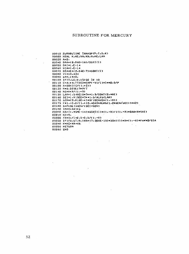
SUBROUTINE FOR MERCURY
00010 SUHROUllNE TRANSPCPPT,SK)00020 REAL KKE.'KAKRPNDNELAM00030 A=2.00040 QAA=(6.96E-i'6)/SQRT(l)00050 0AII-*E-1400060 01A=1.E-1400070 QEAVE=(2.34E-7)*SORT(T)00080 VI=10.43400090 S=O.X=O.00100 IF(T.LE.0.15)G0 TO 1000110 C=4.*4.773E3*EXP(-V1/I)*1**2..b/P00120-X=SORT( C/(. +C))00130 N=6.325E17*P/T00140 NE=N*X/CI.+X)00150 LAM=1.549EO0*T**1.5/S0HT(2-*NE)00160 SEI=1.915E2*T**1.5/AL0(ULAM)00170 SEN=(2-.RIE-4)*X/(OEAVE*(I.-X))00175 F=1.-0.2/(1C(0.-4343*ALOG(I12*SENi/EI))**2)001R0 S=F*SEI*SEN/(SE I +SEN)00190 1OKE=A*T*S00200 KA=(.1 959E-14)*SORT('I')*.(I.-X)/((I.-X)*QAA+X* JAI)00210 KR=O.00220 FR=VI/1+2.5-0.5/(l.-X)00230 IF(FIt.(T.0.)KR=(7-386E-15S)*SOl('l )*X*(I·-X)*FH**2/QIA00240 K=KE+KA+KR.00250 RETURN00260 END
52

SUBROUTINE FOR NaK
SUBROUTINE TRANSP(PTSK)REAL K,KE,KK,KNANNELAMEPS=0.0005A=2.OEKVE=1 .6E-6OENAVE=I.2E-6OKK=5.47E- 5ONANA=3.30E-IS5ONAK=4.32E- 15QKIK=2.E-14QNAINA=1 .5E-14VK=4.3391VNA=5.1 38XK=O.JXKN=O.X NA=O.;XNAN=O.S=0.IFCT.LE.O.I)GO 10 10CK=4.773E3*EXPC-VK/T)*T**2.5/PCNA=4.773E3*EXP(-VNA/T)*T**2.5/P20XKN=CSQRTC(.*CK*(3.+XNA)*(I.+CK)+(CK+XNA*(I-+CK))**2)& -CK-XNA*C(.+CK))/(4.*(1.+CK))XNAN=(SQRT(4.*CNA*C3.+2.*XKN)*(I.+CNA)+(2.*CNA+2-*XKN*& (1.+CNA))**2)-2.*CNA-2.*XKN*(I·+CNA))/(2.*(1 .+CNA))IF(CABS(XKN-XK).LE.(EPS*XK)).AND. (ABS(XNAN-XNA).LE. (EPS*XNA)))& GO TO 30XK=XKN;XNA=XNANG6 TO e030XK=XKN; XNA=XNANN=6.325E17*P/TNE=N* (XK+0.5*XNA)/(1 5+XK+0.5*XNA)LAM=1.549EIO*T** .5/SQORT(2.*NE)SEI=1 .915E2*T**I.5/ALOG(LAM)SEK=(2.818E-4)*(XK+0-5*XNA)/C(EKVE*(I--XK))SENA=(2.818E-4)*(XKO. 5*XNA)/(QENAVE*0.5*(I'-XNA))SEN=SENA*SEK/(SENA+SEK)F=1.-0.09/(1.+(0-4343*ALOG(1.I*SEN/SEI))**2)S=F*SEI*SEN/(SE I+SEN)OKE=A*T*S
KK=(5.021E-14)*SQRT(T)*(I·-XK)/(1.13137*(I;-XK)*QKK& +1.13137*XK**QKIK+1.1868*0.5*QNAK)KNA=C6.548E-14)*SQRT(T)*(1.-XNA)/(1.131i37*(I--XNA)*QNANA& +1.13137*XNA*QNAINNA1.1062*2.*GNAK)K=KE+KK+KNARETURNEND
53
00010000200003000040000500006000070000800009000100001100012000130001400015000160001700018000190002000021000220002300024000250002600027000280002900030000310003200033000340003500036000370003800039000400004100042000430

APPENDIX B
EVALUATION OF THE RADiATION
COOLING MECHANISM OF MERCURY VAPOR ARCS
Dr. L. P. Harris
Although radiation cooling had appeared to be an important factor inthe energy exchange processes of mercury arcs based on earlier calcu-lations some improved calculations indicate that radiation cooling is nota strong factor for arcs experienced in this program. (Refer to Report
CR-72868, p. 81). For a discharge at the blackbody limit (Er = 1),
E<= (z STo4 1 /z
The discharge current is then determined by
J Vt a c(E t,
In these equations E and J are the voltage gradient and current density, t isthe discharge thickness (slab arc) or radius (cylindrical arc), S is the Stefan-Boltzmann constant, T
othe discharge temperature, and cr the plasma con-
ductivity.
Figure 23 shows a comparison with experimental data of the E/vs
Jit characteristic calculated from the preceding equations for mercury.The experiments were done about 1964 with cylindrical discharges of 0. 5to 1.5 millimeter diameter. For values of Jfbelow about 2 x 10 A/cm
the blackbody calculation gives too high a voltage gradient and power dissi-pation, but for JV' > 2 x 10³ A/cm 3 n2 the experimental points appear tofollow the theoretical curve. Thus it appears that mercury arcs over 70amperes in a 1.0 mm diameter channel or over 25.amperes in 0. 5 mmdiameter might be cooled by blackbody radiation.
54

100MERCURY ARCBLACKBODY
80
60
0 0EXP. DATA: Ed IN MM
400 0.5 Go 00 0.75 0 oA 1.025
20 1.25B 1.50
t - 0.5d
0) , , I
E
w
102 103
(A/cm3/2)
Figure 23 - Comparison of Mercury Arc BlackbodyAnalysis with Experimental Data
55

THE FOLLOWING PAGES ARE DUPLICATES OF
ILLUSTRATIONS APPEARING ELSEWHERE IN THIS
REPORT. THEY HAVE BEEN REPRODUCED HERE BY
A DIFFERENT METHOD TO PROVIDE BETTER DETAIL