Embed Size (px)
Citation preview
Nanoscale
COMMUNICATION
Cite this: Nanoscale, 2017, 9, 18194
Received 16th September 2017,Accepted 21st October 2017
DOI: 10.1039/c7nr06902b
rsc.li/nanoscale
Self-assembled nano-leaf/vein bionic structure ofTiO2/MoS2 composites for photoelectric sensors†
Qianyu Wang,a Peng Yu,a Lu Bai,a Ruiying Bao,a Ning Wang,b Chuanbing Cheng,c
Zhengying Liu,a Mingbo Yang, a Wei Yang *a and Zhanhu Guo *c
Inspired by the leaf/vein structure of leaves which effectively sup-
ports the photosynthesis of green plants, a nano-leaf/vein bionic
structure of self-assembled TiO2/MoS2 composites is applied to
induce the reversible photochromic reactions of methylene blue
(MB) for the first time. This reversible photochromic phenomenon
gives a novel performance for the TiO2/MoS2 composites and
expands their applications. Similar to the case where the natural
vein network in leaves ensures the efficient material transfer and
energy exchange for photosynthesis, the bionic internal MoS2 vein
network in the composites ensures the efficient separation and
directional transfer of photo-generated carriers to restrain the
photocatalytic degradation reactions and to enhance the reversible
photochromic reactions. Furthermore, the photosensitive appli-
cations of the TiO2/MoS2/MB systems with such a self-assembled
nano-leaf/vein bionic structure are discussed with two typical
photoelectric sensory models for both controllers and detectors.
1. Introduction
Among the core sensory systems, photoelectric sensors showclear advantages such as high accuracy, rapid response andfavorable stability, owing to their easy control by an artificiallight source, fast detection of light change without physicalcontacts, and quick responses.1 A typical photoelectric sensoris made up of three major elements, i.e., a luminous element,a photosensitive element and a transition element.Photosensitive elements convert photosignals or photoinducedvariates from luminous elements to physical quantity signals,
and finally to electrical signals through transition elements.Thus, the photosensitive element is the most important partthat acts as a bridge to connect the luminous element and thetransition element to ensure the transformation and trans-mission of signals. Nowadays, the most widely applied photo-sensitive elements are photosensitive resistors from varioussemiconductive materials, which give different resistancesunder lumination.2
Methylene blue (MB) is a typical redox dye and exhibits aseries of interesting color switching (bright blue to colorless)reactions through gaining or losing electrons. With thisunique property, MB can be combined with semiconductors toform a reversible photochromic system.3 In this system, therole of the semiconductor is to absorb light and offer photo-generated electrons (e−). Semiconductive TiO2, with its excel-lent photoelectrochemical activity,4,5 has been studied inphotocatalysis6–8 and electrochemistry9–11 including reversiblephotochromic systems with MB.12–15 The irreversible photo-catalytic degradation reaction and reversible color switchingreaction are competing reactions. To ensure color switching,the photocatalytic degradation reactions must be restrained.13
In previous reports, this was generally realized by restrainingthe generation of a hydroxyl radical (*OH) produced by photo-generated holes (h+) and the reaction between the hydroxylradical and the MB solution.16
A typical MB photochromic system, usually containing aMB solution, a semiconductor material (such as TiO2), and asacrificial electron donor (SED, such as poly(ethylene glycol)-b-poly(propylene glycol)-b-poly(ethylene glycol)), has been usedas an oxygen indicator.17,18 In this case, when TiO2 producesphoto-generated electrons and holes under UV lightirradiation, the freely diffusing holes react with the SED.Meanwhile, both low pH13,15 and low oxygen content14,19 canpromote the decoloration process of MB in the TiO2/MB system.O2 has been proved not to be a prerequisite but in that case therole of the SED and strong acidic conditions is indispensable,and the SED material must composite with TiO2 well.16 Manyefforts have been made to release the system from the externalSED but some other materials with SED-like functions such as
†Electronic supplementary information (ESI) available. See DOI: 10.1039/c7nr06902b
aCollege of Polymer Science and Engineering, State Key Laboratory of Polymer
Materials Engineering, Sichuan University, Chengdu 610065, Sichuan, China.
E-mail: [email protected] Multifunctional Composites (EMC) Nanotechnology LLC, Knoxville,
TN 37934, USAcIntegrated Composites Laboratory (ICL), Department of Chemical & Biomolecular
Engineering, University of Tennessee, Knoxville, TN 37996, USA.
E-mail: [email protected]
18194 | Nanoscale, 2017, 9, 18194–18201 This journal is © The Royal Society of Chemistry 2017
Publ
ishe
d on
23
Oct
ober
201
7. D
ownl
oade
d by
Uni
vers
ity o
f T
enne
ssee
at K
noxv
ille
on 3
0/11
/201
7 20
:22:
48.
View Article OnlineView Journal | View Issue
colloidal barium-dopant TiO2 nanocrystals which can produceoxygen vacancies are still needed to consume the photo-gener-ated holes.20,21 In other words, all the previous studies allowedthe photo-generated holes to diffuse to the surface of thematerials freely and then tried to consume them by using somekinds of SED or SED-like materials.
MoS2 with a narrower band gap (1.9 eV) compared with thatof TiO2 (3.2 eV)22,23 has been loaded into TiO2 to enhance itsphotocatalytic activity24,25 because it can form a new hetero-structure with TiO2.
26–28 This heterostructure can realize adirectional transfer of photo-generated carriers under illumi-nation, i.e., the transfer of all photo-generated holes to thevalence band of MoS2 and the simultaneous transfer of allphoto-generated electrons to the conduction band of TiO2.
29,30
Although TiO2/MoS2 composites (TM) have been reported asphotocatalysts for water pollutant degradation26,31–34 andwater splitting hydrogen production,24,35–38 their applicationsin inducing the reversible photochromic reactions of MB havenever been reported. Without MoS2, the TiO2/MB systems aremostly applied in ink-free light-printing.21,39,40
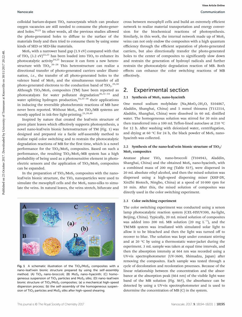
Inspired by nature that created the leaf/vein structure ofgreen plant leaves which effectively supports photosynthesis, anovel nano-leaf/vein bionic heterostructure of TM (Fig. 1) wasdesigned and prepared via a facile self-assembly method torealize rapid color switching and to restrain the photocatalyticdegradation reactions of MB for the first time, which is a novelperformance for the TiO2/MoS2 composites. Based on such aperformance, the resulting TiO2/MoS2-MB system has a highprobability of being used as a photosensitive element in photo-electric sensors and the application of TiO2/MoS2 compositescan be expanded.
In the preparation of TiO2/MoS2 composites with the nano-leaf/vein bionic structure, the TiO2 nanoparticles were used tosimulate the mesophyll cells and the MoS2 nano-silks to simu-late the veins. In natural leaves, the veins stretch, bifurcate and
cross between mesophyll cells and build an extremely efficientnetwork to realize material transportation and energy conver-sion for the biochemical reactions of photosynthesis.Similarly, in this work, the internal network made up of MoS2veins can not only endow the composites with a high quantumefficiency through the efficient separation of photo-generatedcarriers, but also directionally transfer the photo-generatedholes to the center of composites to significantly slow downand restrain the generation of hydroxyl radicals and furtherrestrain the photocatalytic degradation reaction of MB. Botheffects can enhance the color switching reactions of MBeffectively.
2. Experimental section2.1 Synthesis of MoS2 nano-hyacinth
One mmol sodium molybdate (Na2MoO4·2H2O, S104867,Aladdin, Shanghai, China) and 5 mmol thiourea (T112514,Aladdin, Shanghai, China) were dissolved in 60 mL distilledwater. The homogeneous solution was stirred for 30 min andthen transferred into a 100 mL Teflon-lined autoclave at 210 °Cfor 12 h. After washing with deionized water, centrifugation,and drying at 60 °C for 24 h, the black powder of MoS2 nano-hyacinth was collected.
2.2 Synthesis of the nano-leaf/vein bionic structure of TiO2/MoS2 composites
Anatase phase TiO2 nano-broccoli (T104943, Aladdin,Shanghai, China) and the obtained MoS2 nano-hyacinth, witha combined mass of 200 mg (Table S1†), were dispersed in20 mL absolute ethyl alcohol, and then the mixed solution wasdispersed using a high-speed dispersing mixer (XHF-DY,XinZhi Biotech, Ningbo, China) at a speed of 10 000 rpm for10 min. After this, the mixed solution of composites wasdirectly used in the color switching experiment.
2.3 Color switching experiment
The color switching experiment was conducted using a xenonlamp photocatalytic reaction system (CEL-HXUV300, Au-light,Beijing, China). Typically, 20 mL mixed solution of compositeswas added into 200 mL MB solution (20 mg L−1), and theTM/MB system was irradiated with simulated solar light toallow it to be bleached and then the light was turned off torecover to blue. The solution was kept under constant stirringand at 20 °C by using a thermostatic water-jacket during theexperiment. 3 mL sample was taken at equal time intervals, andthen the absorption intensity at 664 nm was recorded using aUV-vis spectrophotometer (UV-3600, Shimadzu, Japan) afterremoving the composites. Each sample was tested through acycle of decoloration and recoloration processes. Because of thelinear relationship between the concentration and the absor-bance at the absorption peak (664 nm) of the visible light waveband of the MB solution (Fig. S6†), the absorbance can bedetected by using a UV-vis spectrophotometer and is used todetermine the concentration of MB (C) in the system.
Fig. 1 A schematic illustration of the TiO2/MoS2 composites with anano-leaf/vein bionic structure prepared by using the self-assemblymethod. (A) TiO2 nano-broccoli; (B) MoS2 nano-hyacinth; (C) homo-geneous suspension of TiO2 particles and MoS2 silks; (D) nano-leaf/veinbionic structure of TiO2/MoS2 composites; (a) a mechanical high-speeddispersion process; (b) the self-assembly of the homogeneous suspen-sion of TiO2 particles and MoS2 silks after high-speed shearing.
Nanoscale Communication
This journal is © The Royal Society of Chemistry 2017 Nanoscale, 2017, 9, 18194–18201 | 18195
Publ
ishe
d on
23
Oct
ober
201
7. D
ownl
oade
d by
Uni
vers
ity o
f T
enne
ssee
at K
noxv
ille
on 3
0/11
/201
7 20
:22:
48.
View Article Online
3. Results and discussion
The TiO2 nano-broccoli (Fig. 1A & Fig. S1a†) and MoS2 nano-hyacinth (Fig. 1B & Fig. S1b†) were selected as the rawmaterials to offer TiO2 nanoparticles and MoS2 nano-silks, anda high-speed dispersing mixer (Fig. 1(a)) was used to achieve ahomogeneous suspension of the nanoparticles and nano-silks(Fig. 1C). The good suspension state was very unstable. Oncethe mixing operation was stopped, the suspended nano-particles and nano-silks quickly rejoined into particle clusters,driven by the high surface energy of good dispersion and sus-pension. In this process, the nano-leaf/vein bionic structure ofTM (Fig. 1D) was built with MoS2 nano-silks inserted betweenthe TiO2 nanoparticles (Fig. 1(b)), and the vein structure canbe regulated by loading different contents of MoS2 nano-silks.
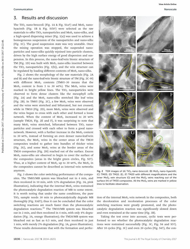
Fig. 2 shows the morphology of the raw materials (Fig. 2Aand B) and the nano-leaf/vein bionic structure of TM (Fig. 2C–H)with different MoS2 contents (TM05–30 means that theMoS2 content is from 5 to 30 wt%). The MoS2 veins weremarked in bright yellow lines. The TiO2 nanoparticles wereobserved to form dense clusters like the mesophyll cells(Fig. 2A) and the MoS2 nano-silks stretched like leaf veins(Fig. 2B). In TM05 (Fig. 2C), a few MoS2 veins were observedand the veins were stretched and bifurcated, but not crossed;while in TM10 (Fig. 2D), more MoS2 veins were observed andthe veins began to cross with each other and formed a loosenetwork. When the content of MoS2 increased to 20 wt%(sample TM20, Fig. 2E and F), it was surprising to note thatmany MoS2 veins stretched, bifurcated between TiO2 nano-particles and crossed with each other to form a good nano-network. However, with a further increase in the MoS2 contentto 30 wt%, instead of forming an even denser nano-leaf/veinstructure, the MoS2 veins in the center areas of the TM30composites tended to gather into bundles of thicker veins(Fig. 2G), and some MoS2 veins at the border areas of theTM30 composites (Fig. 2H) reached out of the surface. ExcessMoS2 nano-silks are observed to begin to cover the surface ofthe composites (areas in the bright green circles, Fig. S2†).Thus, at a higher content of MoS2 up to 30 wt%, the MoS2 inthe composites cannot be described as internal vein networksanymore.
Fig. 3 shows the color switching performance of the compo-sites. The TM05/MB system was bleached out in 4 min, andthen recolored in 10 min, with 12% degradation (Fig. 3A, pinkillustration), indicating that the internal MoS2 veins restrainedthe photocatalytic degradation reaction of MB to some extent.It is worth noting that under the same conditions, the pureTiO2 sample needs 30 min to photocatalytically degrade MBthoroughly (Fig. S3d†); thus it can be concluded that the colorswitching reactions are much faster than the photocatalyticdegradation reactions.38 The TM10/MB system was bleachedout in 2 min, and then recolored in 4 min, with only 4% degra-dation (Fig. 3A, orange illustration); the TM20/MB system wasbleached out as fast as 0.5 min, and then recolored in just1 min, with merely 2% degradation (Fig. 3A, green illustration).These results demonstrate that with the formation and perfec-
tion of the internal MoS2 vein network in the composites, boththe decoloration and recoloration processes of the colorswitching reactions were greatly promoted, and the photo-catalytic degradation reaction was significantly slowed downand even restrained at the same time (Fig. 3B).
Taking the test error into account, cyclic tests were per-formed to see whether the photocatalytic degradation reac-tions were restrained successfully (Fig. 3C, Fig. S4 and S5†).After 10 cycles (Fig. 3C) and even 20 cycles (Fig. S4†), the con-
Fig. 2 TEM images of (A) TiO2 nano-broccoli; (B) MoS2 nano-hyacinth;(C) TM05; (D) TM10; (E), (F) TM20 with different magnifications and theinner MoS2 vein structure (G) and the MoS2 veins reaching out of thesurface (H) of TM30 composites. All the MoS2 veins are marked in yellowlines to facilitate observation.
Communication Nanoscale
18196 | Nanoscale, 2017, 9, 18194–18201 This journal is © The Royal Society of Chemistry 2017
Publ
ishe
d on
23
Oct
ober
201
7. D
ownl
oade
d by
Uni
vers
ity o
f T
enne
ssee
at K
noxv
ille
on 3
0/11
/201
7 20
:22:
48.
View Article Online

centration of MB in TM20/MB was still maintained very closeto the initial value, while after only 10 cycles, the concentrationof MB in TM10/MB showed a clear drop (Fig. S5†) with about9.7% of MB degraded. This result clearly demonstrates thatonly the TM20 composites can effectively restrain the photo-catalytic degradation reaction of MB.
However, the TM30/MB system took 8 min to bleach outbut only 2 min to recover (Fig. 3A, blue illustration) and thedegradation percentage of MB was up to 32%. Apparently, theTM30 composites cannot restrain the photocatalytic degra-dation reaction of MB because the MoS2 veins stretch out ofthe surface of composites and ruin the directional transferringeffect of the internal MoS2 vein network on the photo-gener-ated carriers. These stretched-out MoS2 veins can evenpromote the photocatalytic degradation, and in this case, thecomposite structure is just like the core–shell TiO2–MoS2 struc-tures that were designed for better photocatalytic activity andapplied for enhancing the photocatalytic degradation reac-tions.26,32 The recoloration process of the TM30/MB systemseems to be much faster due to the 66% degradation-induceddecrease of the entire MB content (Fig. 3B) after the firstbleaching process.
The rates of the decoloration/recoloration process of thesamples were also calculated based on the absorbance changein a decoloration or recoloration process and the consumedtime (Fig. 3D). The results demonstrated that the formation ofthe internal MoS2 vein network could sharply increase the rateof both the decoloration and recoloration processes, whichalso clearly proved the extremely high quantum efficiency ofthe designed nano-leaf/vein bionic structures. Compared withthe TiO2/MB systems reported previously,16,39 such a nano-
leaf/vein bionic structured TM/MB system shows a rapid colorrecovery rate as high as 1.1 Abs min−1, much higher thanother samples (Fig. 3D) without any light illumination or extraheating. Because the photocatalytic degradation was not wellrestrained in the TM30/MB system, the color switching ratewas very low. Besides this, bulk MoS2 (Fig. S3a and b†) wasalso used to replace MoS2 nano-hyacinth and to prepare acontrol sample for the TM20 composites, but only a not well-composited structure (Fig. S3c†) with a slightly enhancedphotocatalytic degradation was obtained (Fig. S3d†).
With such an excellent color switching performance, theTM20/MB system can be used as a photosensitive element inphotoelectric sensors (Fig. 4A). Devices of different sizes canbe built (Fig. 4A(a)) according to the requirements of practicalapplications. In particular, this TM20/MB system shows clearadvantages in microminiaturization, which gives the TM20/MBsystem great potential to be used in micron and precisesensors. Furthermore, the color switching performance isimpregnable after scaling (Fig. 4A(b)). A typical photoelectricsensor can be constructed by combining the TM20/MB systemwith a photosource and a photometer (Fig. 4B(a)), and thesensor can realize the transformation of signals (Fig. 4B(b)).This modularized method will certainly endow the system withmore flexibility in applications.
Practically, there are mainly two types of photoelectricsensors, i.e., controllers and detectors. For controllers, thephotosensitive element transforms controllable photosignalsto the given electric signals to control the targets, while fordetectors, the photosensitive element detects the photosignalstransformed from the electric signals given by the target. Foreach type, a typical sensory model was given to expound thepractical applications of the TM20/MB system. “A” means theabsorbance value of the TM20/MB system, and “ΔA” meansthe rate of change of “A”. “A” can be measured by using aphotometer every second, and “ΔA” per second can be calcu-lated at the same time.
In the controller model (Fig. 4C(a)), the TM20/MB systemcan be used to control the traffic light circuit (Fig. 4C(b)). Ineach cycle of the system, when “A” changes from 1.6 (theabsorbance value of 20 mg L−1 MB according to Fig. S6†) to 0,and then recovers from 0 to 1.6, the red, yellow and greentraffic lights can be turned on and off successively. Thisprocess can also be suspended to maintain a signal withoutany energy consumption, unlike the case where the photo-diode needs a sustaining extra illumination and electricity tohold a signal.
In the detector model (Fig. 4D), because of the linearrelationship between the rate of change of absorbance “ΔA”and the optical power density “B” (Fig. S7†), if there exists anyother physical quantity “C” which can lead to a change of “B”and has a relation with “B”, then a relationship between “A”and “C” can be constructed, where “C” is the goal to bedetected. Then, all we need to do is just to detect the rate ofchange of absorbance of the TM20/MB system, and the valueof “C” can be easily detected immediately. Considering somany “C” in this world, such as the material concentration,
Fig. 3 Color switching: (A) the decoloration and recoloration processesof the samples with respect to time; the original data are shown inFig. S9;† (B) color switching/degradation percentage of the samples; (C)cyclic test of TM20/MB; (D) color switching rate of the samples. C/C0:the ratio of the tested concentration and the original concentration ofMB; rate: the absorbance change in a decoloration or recolorationprocess (Abs) within the consumed time (min).
Nanoscale Communication
This journal is © The Royal Society of Chemistry 2017 Nanoscale, 2017, 9, 18194–18201 | 18197
Publ
ishe
d on
23
Oct
ober
201
7. D
ownl
oade
d by
Uni
vers
ity o
f T
enne
ssee
at K
noxv
ille
on 3
0/11
/201
7 20
:22:
48.
View Article Online
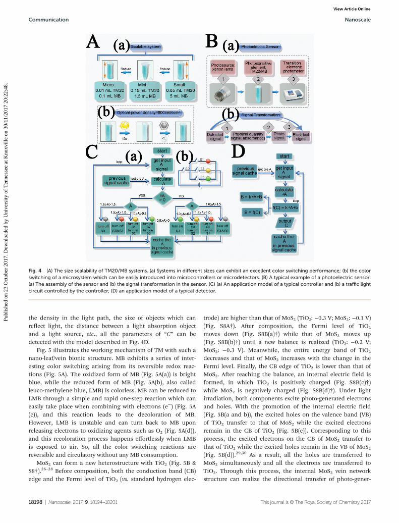
the density in the light path, the size of objects which canreflect light, the distance between a light absorption objectand a light source, etc., all the parameters of “C” can bedetected with the model described in Fig. 4D.
Fig. 5 illustrates the working mechanism of TM with such anano-leaf/vein bionic structure. MB exhibits a series of inter-esting color switching arising from its reversible redox reac-tions (Fig. 5A). The oxidized form of MB (Fig. 5A(a)) is brightblue, while the reduced form of MB (Fig. 5A(b), also calledleuco-methylene blue, LMB) is colorless. MB can be reduced toLMB through a simple and rapid one-step reaction which caneasily take place when combining with electrons (e−) (Fig. 5A(c)), and this reaction leads to the decoloration of MB.However, LMB is unstable and can turn back to MB uponreleasing electrons to oxidizing agents such as O2 (Fig. 5A(d)),and this recoloration process happens effortlessly when LMBis exposed to air. So, all the color switching reactions arereversible and circulatory without any MB consumption.
MoS2 can form a new heterostructure with TiO2 (Fig. 5B &S8†).26–28 Before composition, both the conduction band (CB)edge and the Fermi level of TiO2 (vs. standard hydrogen elec-
trode) are higher than that of MoS2 (TiO2: −0.3 V; MoS2: −0.1 V)(Fig. S8A†). After composition, the Fermi level of TiO2
moves down (Fig. S8B(a)†) while that of MoS2 moves up(Fig. S8B(b)†) until a new balance is realized (TiO2: −0.2 V;MoS2: −0.3 V). Meanwhile, the entire energy band of TiO2
decreases and that of MoS2 increases with the change in theFermi level. Finally, the CB edge of TiO2 is lower than that ofMoS2. After reaching the balance, an internal electric field isformed, in which TiO2 is positively charged (Fig. S8B(c)†)while MoS2 is negatively charged (Fig. S8B(d)†). Under lightirradiation, both components excite photo-generated electronsand holes. With the promotion of the internal electric field(Fig. 5B(a and b)), the excited holes on the valence band (VB)of TiO2 transfer to that of MoS2 while the excited electronsremain in the CB of TiO2 (Fig. 5B(c)). Corresponding to thisprocess, the excited electrons on the CB of MoS2 transfer tothat of TiO2 while the excited holes remain in the VB of MoS2(Fig. 5B(d)).29,30 As a result, all the holes are transferred toMoS2 simultaneously and all the electrons are transferred toTiO2. Through this process, the internal MoS2 vein networkstructure can realize the directional transfer of photo-gener-
Fig. 4 (A) The size scalability of TM20/MB systems. (a) Systems in different sizes can exhibit an excellent color switching performance; (b) the colorswitching of a microsystem which can be easily introduced into microcontrollers or microdetectors. (B) A typical example of a photoelectric sensor.(a) The assembly of the sensor and (b) the signal transformation in the sensor. (C) (a) An application model of a typical controller and (b) a traffic lightcircuit controlled by the controller; (D) an application model of a typical detector.
Communication Nanoscale
18198 | Nanoscale, 2017, 9, 18194–18201 This journal is © The Royal Society of Chemistry 2017
Publ
ishe
d on
23
Oct
ober
201
7. D
ownl
oade
d by
Uni
vers
ity o
f T
enne
ssee
at K
noxv
ille
on 3
0/11
/201
7 20
:22:
48.
View Article Online
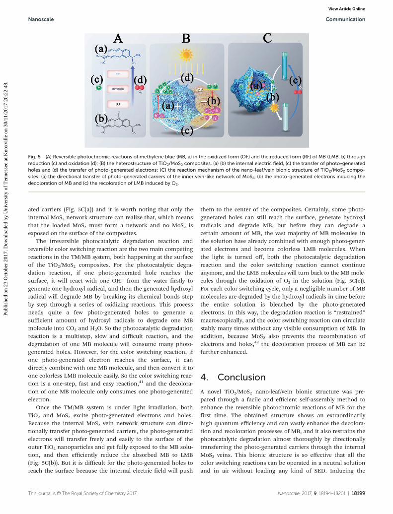
ated carriers (Fig. 5C(a)) and it is worth noting that only theinternal MoS2 network structure can realize that, which meansthat the loaded MoS2 must form a network and no MoS2 isexposed on the surface of the composites.
The irreversible photocatalytic degradation reaction andreversible color switching reaction are the two main competingreactions in the TM/MB system, both happening at the surfaceof the TiO2/MoS2 composites. For the photocatalytic degra-dation reaction, if one photo-generated hole reaches thesurface, it will react with one OH− from the water firstly togenerate one hydroxyl radical, and then the generated hydroxylradical will degrade MB by breaking its chemical bonds stepby step through a series of oxidizing reactions. This processneeds quite a few photo-generated holes to generate asufficient amount of hydroxyl radicals to degrade one MBmolecule into CO2 and H2O. So the photocatalytic degradationreaction is a multistep, slow and difficult reaction, and thedegradation of one MB molecule will consume many photo-generated holes. However, for the color switching reaction, ifone photo-generated electron reaches the surface, it candirectly combine with one MB molecule, and then convert it toone colorless LMB molecule easily. So the color switching reac-tion is a one-step, fast and easy reaction,41 and the decolora-tion of one MB molecule only consumes one photo-generatedelectron.
Once the TM/MB system is under light irradiation, bothTiO2 and MoS2 excite photo-generated electrons and holes.Because the internal MoS2 vein network structure can direc-tionally transfer photo-generated carriers, the photo-generatedelectrons will transfer freely and easily to the surface of theouter TiO2 nanoparticles and get fully exposed to the MB solu-tion, and then efficiently reduce the absorbed MB to LMB(Fig. 5C(b)). But it is difficult for the photo-generated holes toreach the surface because the internal electric field will push
them to the center of the composites. Certainly, some photo-generated holes can still reach the surface, generate hydroxylradicals and degrade MB, but before they can degrade acertain amount of MB, the vast majority of MB molecules inthe solution have already combined with enough photo-gener-ated electrons and become colorless LMB molecules. Whenthe light is turned off, both the photocatalytic degradationreaction and the color switching reaction cannot continueanymore, and the LMB molecules will turn back to the MB mole-cules through the oxidation of O2 in the solution (Fig. 5C(c)).For each color switching cycle, only a negligible number of MBmolecules are degraded by the hydroxyl radicals in time beforethe entire solution is bleached by the photo-generatedelectrons. In this way, the degradation reaction is “restrained”macroscopically, and the color switching reaction can circulatestably many times without any visible consumption of MB. Inaddition, because MoS2 also prevents the recombination ofelectrons and holes,42 the decoloration process of MB can befurther enhanced.
4. Conclusion
A novel TiO2/MoS2 nano-leaf/vein bionic structure was pre-pared through a facile and efficient self-assembly method toenhance the reversible photochromic reactions of MB for thefirst time. The obtained structure shows an extraordinarilyhigh quantum efficiency and can vastly enhance the decolora-tion and recoloration processes of MB, and it also restrains thephotocatalytic degradation almost thoroughly by directionallytransferring the photo-generated carriers through the internalMoS2 veins. This bionic structure is so effective that all thecolor switching reactions can be operated in a neutral solutionand in air without loading any kind of SED. Inducing the
Fig. 5 (A) Reversible photochromic reactions of methylene blue (MB, a) in the oxidized form (OF) and the reduced form (RF) of MB (LMB, b) throughreduction (c) and oxidation (d); (B) the heterostructure of TiO2/MoS2 composites, (a) (b) the internal electric field, (c) the transfer of photo-generatedholes and (d) the transfer of photo-generated electrons; (C) the reaction mechanism of the nano-leaf/vein bionic structure of TiO2/MoS2 compo-sites: (a) the directional transfer of photo-generated carriers of the inner vein-like network of MoS2, (b) the photo-generated electrons inducing thedecoloration of MB and (c) the recoloration of LMB induced by O2.
Nanoscale Communication
This journal is © The Royal Society of Chemistry 2017 Nanoscale, 2017, 9, 18194–18201 | 18199
Publ
ishe
d on
23
Oct
ober
201
7. D
ownl
oade
d by
Uni
vers
ity o
f T
enne
ssee
at K
noxv
ille
on 3
0/11
/201
7 20
:22:
48.
View Article Online
reversible photochromic reactions of MB by the TiO2/MoS2composites for the first time gives a novel performance andpossible application to these composites. Based on such aperformance, the TM20/MB system can be used as a photo-sensitive element in photoelectric sensors, and with its excel-lent performance and flexible application model, this novelsystem holds great potential in practical applications such ascontrollers and detectors.
Conflicts of interest
The authors declared that they have no conflicts of interest tothis work.
Acknowledgements
This research was financially supported by the NationalNatural Science Foundation of China (NNSFC Grant No.51422305 and 51421061), the Sichuan Provincial Science Fundfor Distinguished Young Scholars (2015JQO003), and the StateKey Laboratory of Polymer Materials Engineering (Grant No.sklpme2014-2-02).
References
1 C. J. Zheng, Intelligence Computation and EvolutionaryComputation, Springer, Berlin, Heidelberg, 2013, vol. 180,pp. 671–677.
2 J. H. Li, L. Y. Niu, Z. J. Zheng and F. Yan, Adv. Mater., 2014,26, 5239–5273.
3 H. Yoneyama, H. Tamura and Y. Toyoguch, J. Phys. Chem.,1972, 76(23), 3460.
4 X. Xu, Z. Y. Fan, S. J. Ding, D. M. Yu and Y. P. Du,Nanoscale, 2014, 6(10), 5245–5250.
5 Z. Q. Liu, X. H. Cao, B. Wang, M. Xia, S. Lin, Z. H. Guo,X. M. Zhang and S. Y. Gao, J. Power Sources, 2017, 342, 452–459.
6 K. S. Ranjith and T. Uyar, J. Mater. Chem. A, 2017, 5(27),14206–14219.
7 L. Zhang, W. Yu, C. Han, J. Guo, Q. H. Zhang, H. Y. Xie,Q. Shao, Z. G. Sun and Z. H. Guo, J. Electrochem. Soc., 2017,164(9), H651–H656.
8 Y. M. Zhao, Y. Z. Dong, F. T. Lu, C. G. Ju, L. Liu, J. Zhang,B. Zhang and Y. Q. Feng, J. Mater. Chem. A, 2017, 5(29),15380–15389.
9 S. M. Guo, J. R. Liu, S. Qiu, W. Liu, Y. R. Wang, N. N. Wu,J. Guo and Z. H. Guo, J. Mater. Chem. A, 2015, 3(47), 23895–23904.
10 B. Chen, N. Q. Zhao, L. C. Guo, F. He, C. S. Shi, C. N. He,J. J. Li and E. Z. Liu, Nanoscale, 2015, 7(30), 12895–12905.
11 X. M. Lou, C. F. Lin, Q. Luo, J. B. Zhao, B. Wang, J. B. Li,Q. Shao, X. K. Guo, N. Wang and Z. H. Guo, ChemElectroChem,2017, DOI: 10.1002/celc.201700816, in press.
12 T. Tatsuma, S. Tachibana, T. Miwa, D. Tryk andA. Fujishima, J. Phys. Chem. B, 1999, 103(38), 8033–8035.
13 A. Mills and J. S. Wang, J. Photochem. Photobiol., A, 1999,127(1–3), 123–134.
14 S. Yamazaki and N. Nakamura, J. Photochem. Photobiol., A,2008, 193(1), 65–71.
15 S. Sohrabnezhad, Spectrochim. Acta, Part A, 2011, 81(1),228–235.
16 W. S. Wang, M. M. Ye, L. He and Y. D. Yin, Nano Lett.,2014, 14(3), 1681–1686.
17 S. K. Lee, A. Mills and A. Lepre, Chem. Commun., 2004, 7,1912–1913.
18 S. K. Lee, M. Sheridan and A. Mills, Chem. Mater., 2005,17(10), 2744–2751.
19 A. Mills, A. Belghazi, R. H. Davies, D. Worsley and S. J. Morris,J. Photochem. Photobiol., A, 1994, 79(1–2), 131–139.
20 W. S. Wang, Y. F. Ye, J. Feng, M. F. Chi, J. H. Guo andY. D. Yin, Angew. Chem., Int. Ed., 2015, 54(4), 1321–1326.
21 M. Imran, A. Yousaf, X. Zhou, K. Liang, Y. F. Jiang andA. W. Xu, Langmuir, 2016, 32(35), 8980–8987.
22 W. G. Tu, Y. C. Li, L. B. Kuai, Y. Zhou, Q. F. Xu, H. J. Li,X. Y. Wang, M. Xiao and Z. G. Zou, Nanoscale, 2017, 9(26),9065–9070.
23 J. Hu, Z. K. Guo, P. Mcwilliams, J. Darges, D. Druffel,A. Moran and S. Warren, Nano Lett., 2016, 16(1), 74–79.
24 H. D. Li, Y. N. Wang, G. H. Chen, Y. H. Sang, H. D. Jiang,J. T. He, X. Li and H. Liu, Nanoscale, 2016, 8(11), 6101–6109.
25 A. Rai, A. Valsaraj, A. Roy, R. Ghosh, S. Sonde, S. Kang,J. Chang, T. Trivedi, R. Dey, S. Guchhait, S. Larentis,L. Register, E. Tutuc and S. Baneryee, Nano Lett., 2015,15(7), 4329–4336.
26 C. X. Wang, H. H. Lin, Z. Y. Liu, J. P. Wu, Z. Z. Xu andC. Zhang, Part. Part. Syst. Charact., 2016, 33(4), 221–227.
27 M. M. Ali and K. N. Y. Sandhya, New J. Chem., 2016, 40(9),8123–8130.
28 L. Cao, R. Wang, D. X. Wang, X. Y. Li and H. Y. Jia, Mater.Lett., 2015, 160, 286–290.
29 H. Feng, N. Tang, S. B. Zhang, B. Liu and Q. Y. Cai,J. Colloid Interface Sci., 2017, 486, 58–66.
30 M. X. Sun, Y. Wang, Y. L. Fang, S. F. Sun and Z. S. Yu,J. Alloys Compd., 2016, 684, 335–341.
31 N. Shao, J. N. Wang, D. D. Wang and P. Corvini, Appl.Catal., B, 2017, 203, 964–978.
32 X. F. Liu, Z. P. Xing, Y. Zhang, Z. Z. Li, X. Y. Wu, S. Y. Tan,X. J. Yu, Q. Zhu and W. Zhou, Appl. Catal., B, 2017, 201,119–127.
33 W. Y. Gao, M. Q. Wang, C. X. Ran and L. Li, Chem.Commun., 2015, 51(9), 1709–1712.
34 B. Pourabbas and B. Jamshidi, Chem. Eng. J., 2008,138(1–3), 55–62.
35 H. Y. He, J. H. Lin, W. Fu, X. L. Wang, H. Wang, Q. S. Zeng,Q. Gu, Y. M. Li, C. Yan, B. K. Tay, C. Xue, X. Hu,S. Pantelides, W. Zhou and Z. Liu, Adv. Energy Mater., 2016,6(14), 252–258.
36 R. Lin, Z. H. Zhu, X. Yu, Y. Zhong, Z. L. Wang, S. Z. Tan,C. X. Zhao and W. J. Mai, J. Mater. Chem. A, 2017, 5(2), 814–821.
Communication Nanoscale
18200 | Nanoscale, 2017, 9, 18194–18201 This journal is © The Royal Society of Chemistry 2017
Publ
ishe
d on
23
Oct
ober
201
7. D
ownl
oade
d by
Uni
vers
ity o
f T
enne
ssee
at K
noxv
ille
on 3
0/11
/201
7 20
:22:
48.
View Article Online

37 Y. J. Yuan, Z. J. Ye, H. W. Lu, B. Hu, Y. H. Li, D. Q. Chen,J. S. Zhong, Z. T. Yu and Z. G. Zou, ACS Catal., 2016, 6(2),532–541.
38 S. Bai, L. M. Wang, X. Y. Chen, J. T. Du and Y. J. Xiong,Nano Res., 2015, 8(1), 175–183.
39 W. S. Wang, N. Xie, L. Heand and Y. D. Yin, Nat. Commun.,2014, 5, 5459.
40 W. S. Wang, J. Feng, Y. F. Ye, F. L. Lyu, Y. S. Liu, J. H. Guoand Y. D. Yin, Nano Lett., 2017, 17(2), 755–761.
41 K. Doushita and T. Kawahara, J. Sol-Gel Sci. Technol., 2001,22(1–2), 91–98.
42 T. Z. Lin, B. T. Kang, M. Jeon, C. Huffman, J. Jeon, S. Lee,W. Han, J. Y. Lee, S. Lee, G. Yeom and K. Kim, ACS Appl.Mater. Interfaces, 2015, 7(29), 11589–15892.
Nanoscale Communication
This journal is © The Royal Society of Chemistry 2017 Nanoscale, 2017, 9, 18194–18201 | 18201
Publ
ishe
d on
23
Oct
ober
201
7. D
ownl
oade
d by
Uni
vers
ity o
f T
enne
ssee
at K
noxv
ille
on 3
0/11
/201
7 20
:22:
48.
View Article Online