Embed Size (px)
Citation preview

August 2008
SELECTION OF DESIGN AND CONSTRUCTION STANDARDS
EUROPEAN UNION REPUBLIC OF MOLDOVA
FEASIBILITY STUDY FOR THE REHABILITATION AND EXTENSION OF THE ROAD M3 CHISINAU – GIURGIULESTI/ROMANIAN BORDER
Europe Aid/125919/C/SER/MD
Koblenz, Germany Chisinau, Moldova

Road M3 Chisinau — Giurgiulesti/ Romanian Border Extension and Rehabilitation Project Selection of Design and Construction Standards
Kocks Consult GmbH in association with Universinj ltd
CONTENT 1. Introduction and Background 2. Geometric Road Design Standards 2.1 Geometric Road Design Standards in Moldova 2.2 Selection and Application of Standards 2.2.1 Overview of Cross Section Design Parameters 2.2.1.1 Lane Width 2.2.1.2 Shoulders 2.2.1.3 Cross Slope 2.2.1.4 Shoulder Slopes 2.2.2 Overview of Alignment Design Parameters 2.2.2.1 Design Speed 2.2.2.2 Horizontal Curvature 2.2.2.3 Maximum Gradient 2.2.2.4 Minimum Radius of Crest (Convex) Vertical Curves 2.2.2.5 Minimum Radius of Sag (Concave) Vertical Curves 2.3 Recommendation for Application of Geometric Design Standards 2.4 Relaxation of Standards 3. Pavement Design Standards 3.1 General Design Principles 3.2 Pavement Types 3.3 Design Parameters 3.4 Discussion and Review of Pavement Design Standards 3.5 Assessment of Pavement Design Standards and Recommendations 4. Bridge Design Standards 4.1 Bridge Design Standard in Moldova 4.2 Review of Existing Bridge Design Standard 4.3 Structural Principles according to Standard Drawings 4.4 `Assessment of Bridge Design Standards and Recommendations 5. Construction Standards ANNEXES 1. List of Major Former Soviet Union Standards Related to Roads and Bridges 2. Typical Cross-Sections for Two Lane Arterial and Local Roads

Road M3 Chisinau — Giurgiulesti/ Romanian Border Extension and Rehabilitation Project 1 Selection of Design and Construction Standards
Kocks Consult GmbH in association with Universinj ltd
1. Introduction and Background Geometric road design standards in Moldova are still based on FSU standards, although initiatives are under way to introduce European norms. Therefore the Terms of Reference of the Road M3 Chisinau – Giurgiulesti/Romanian Border Extension and Rehabilitation Project emphasise that the applicable design and construction standards should be consistant with representative international design and construction standards. This document discusses established FSU standards, recent Moldovan modifications to the FSU standards, as well as applicable international standards. The Chisinau - Giurgiulesti road rehabilitation project will rehabilitate a road corridor linking Chisinau with the southern region in Moldova, with Giurgiulesti port, including connections to the borders with Romania and Ukraine. Experience in Western European countries has shown that more appropriate geometric and pavement design standards are just some of the areas where large savings in costs and increases in efficiency can be made. The cost effective road design requires a thorough understanding of the complex interactions of soils, terrain, climate, and traffic. Moreover, creating sustainable solutions to the problems posed by these interactions requires a significant level of engineering judgment, technical skills, and local knowledge. Standard solutions are often insufficient. Terrain conditions can vary considerably within countries and between regions. Traffic types and needs depend on the circumstances of individual communities. To achieve cost-effective solution, it is important to tailor interventions to the specific situation and not to impose rigid designs. One of the principal objectives of this report is to make recommendations about the geometric design and construction standards for the Chisinau - Giurgiulesti Road Rehabilitation Project such that the optimum balance between road construction cost and road user cost is obtained, considering road safety issues and natural and human environmental aspects. 2. Geometric Design Standards Geometric design is the process whereby the layout of the road in the terrain is designed to meet the need of the road users. The principal geometric features are the road cross-section and horizontal and vertical alignment. Geometric design standards are not more than a first approximation to design needs, since it should be accepted that design must be site specific. The optimal design for a given traffic flow will depend on terrain and other characteristics. The use of geometric design standards fulfills three inter-related objectives. Firstly, standards are intended to provide minimum levels of safety and comfort for drivers by the provision of adequate sight distances, coefficients of friction and road space for vehicle maneuvers; secondly, they provide the framework for economic design; and thirdly, they ensure a consistency of alignment. The design standards adopted must take also into account the environmental road conditions, traffic characteristics, and driver behavior. During the last years, an emphasis has been placed on existing flexibility in design guidelines and the use of creative design in addressing the site-specific project needs has been encouraged. This philosophy was coined in the USA as context-sensitive design and represents an approach in which balance is sought between safety, environmental, economic and mobility needs.

Road M3 Chisinau — Giurgiulesti/ Romanian Border Extension and Rehabilitation Project 2 Selection of Design and Construction Standards
Kocks Consult GmbH in association with Universinj ltd
2.1 Geometric Design Standards in Moldova The design, construction, improvement and maintenance of roads in Moldova are still carried out according to the provisions of various technical standards of the former Soviet Union (FSU). According to the Soviet Union Standard (SNIP) 2.05.02-85 roads are classified into five categories. The category of the road is determined according to its importance for the national economy and administrative value of the road. At the same time further traffic volumes are considered. The traffic volume indicated is the projected figure at the end of the design period. Table: Road Categories in the former Soviet Union
Traffic volume (ADT) Road Category PCU Vehicles
Economic and administrative value of roads
I-a 14,000 7,000 Highways of state value (including international connection)
I-b II
> 14,000 6,000 – 14,000
> 7,000 3,000 – 7,000
Highways of state (not referred to I-a cat.), republican and regional value
III 6,000 – 14,000 1,000 – 3,000 Roads of state, republican, regional value (not referred to I-b and II cat.), roads of local importance
IV 200 – 6,000 100- 1,000 Roads of republican, regional and local value
V > 200 > 100 Roads of local value
Source: Soviet Union Standard (SNIP) 2.05.02-85, 1986
Notes: PCU – Passenger Car Units Cars PCU value = 1.0 Truck, 2 tonnes PCU value = 1.5 Truck, 6 tonnes PCU value = 2.0 Truck, 8 tonnes PCU value = 2.5 Truck, 14 tonnes PCU value = 3.0 Truck, > 14 tonnes PCU value = 3.5 Bus PCU value = 2.5 The combination of two parameters of different nature in classifying a road, i.e. administrative value and traffic volumes, leads to confusions about an adequate classification of roads and technically unjustified mix of levels of service and recommendations for upgrading. Based on the selected road category the geometrical elements are defined. The main parameters are summarised in the following table. Table: Geometrical Design Standard
Design Speed (km/h) Lane width
Carriage-way
Width of Shoulder
Width of Median
Total Road Road category
normal rolling terrain
difficult terrain
No. of lanes
(m)
(m)
total (m)
paved (m)
total (m)
paved (m)
Width (m)
I-a 150 120 80 4, 6 or 8
3.75 2 x 7.50 or 2 x 11.25
or 2 x 15.00
3.75 0.75 6.00 1.00 28.50 or 38.00 or
43.50
I-b 120 100 60 4, 6 or 8
3.75 2 x 7.50 or 2 x 11.25
or 2 x 15.00
3.75 0.75 5.00 1.00 27.50 or 35.00 or
42.50
II 120 100 60 2 3.75 7.50 3.75 0.75 - - 15.00
III 100 80 50 2 3.50 7.00 2.50 0.50 - - 12.00
IV 80 60 40 2 3.00 6.00 2.00 0.50 - - 10.00
V 60 40 30 1 - 4.50 1.75 - - - 8.00
Source: SNIP 2.05.02-85, 1986

Road M3 Chisinau — Giurgiulesti/ Romanian Border Extension and Rehabilitation Project 3 Selection of Design and Construction Standards
Kocks Consult GmbH in association with Universinj ltd
According to SNIP 2.05.02-85 standard the project roads are classified from category I to IV road. The proposed main determinants for the project roads according to SNIP standards are summarised below. M 3 Chisinau – Giurgiulesti
Existing Proposed
Section Length
Existing Road Cat.
Design Speed
(1)
Paved Roadway
Width (2)
Gravel Shoulder
Width (3)
Minimum Horizontal
Curves (4)
Max. Grade
(km) (km/h) (m) (m) (m) (%) Chişinău- Porumbrei
34 I 80-100
15.0 3.0 400 6,0
Porumbrei-Valea Perjei, (intersection with R 3) (5)
14 IV 30-60-80
8,0 1,0 30 7,0
Intersection with R 3 – Cimislia (coincides with R3 Chişinău-Hînceşti-Cimişlia-Basarabeasca)
12 III 60-100 8.0 1,0 150 1,5
Cimişlia -Comrat 32 III 60-100 8.0 1,0 60 7,0
Comrat -Ciumai 60 III 60-100 8.0 1,0 200 3,0
Ciumai – Vulcaneşti village (bypass section Ciumai - Burlăceni – Vulcaneşti village)
16 IV 60-80 8.0 0,5 60-100 7,0
St. Vulcaneşti- Vulcaneşti town
9 III 60-80 8.0 0,5 150 6,0
Vulcaneşti town- Giurgiuleşti
40 IV 60-80 8.0 0,5 40 7,0
Notes: (1) Maximum speed pertains to normal terrain, minimum to difficult terrain
(2) Including width of paved shoulder (3) In difficult terrain the shoulder width can be reduced to 1.0 m (4) The minimum radius for serpentines is 20 m (5) On an existent section of 400m the maximum grade reaches 10,5%
2.2 Selection and Application of Standards In order to comment on the consistency of applicable design and construction standards in Moldova with representative international standards, main parameters of the geometrical design standards have been compared with various internationally recognised modern standards. However, it should be noted that the application of design standards for a rehabilitation project is usual inherently different from a new construction project, especially considering that the project roads are expected to follow the existing road alignments. It is widespread practice that for these projects, the existing design elements are maintained at their existing values, with the possible exception of limited improvements of geometric characteristics to eliminate safety hazards.
Road M3 Chisinau — Giurgiulesti/ Romanian Border Extension and Rehabilitation Project 4 Selection of Design and Construction Standards
Kocks Consult GmbH in association with Universinj ltd
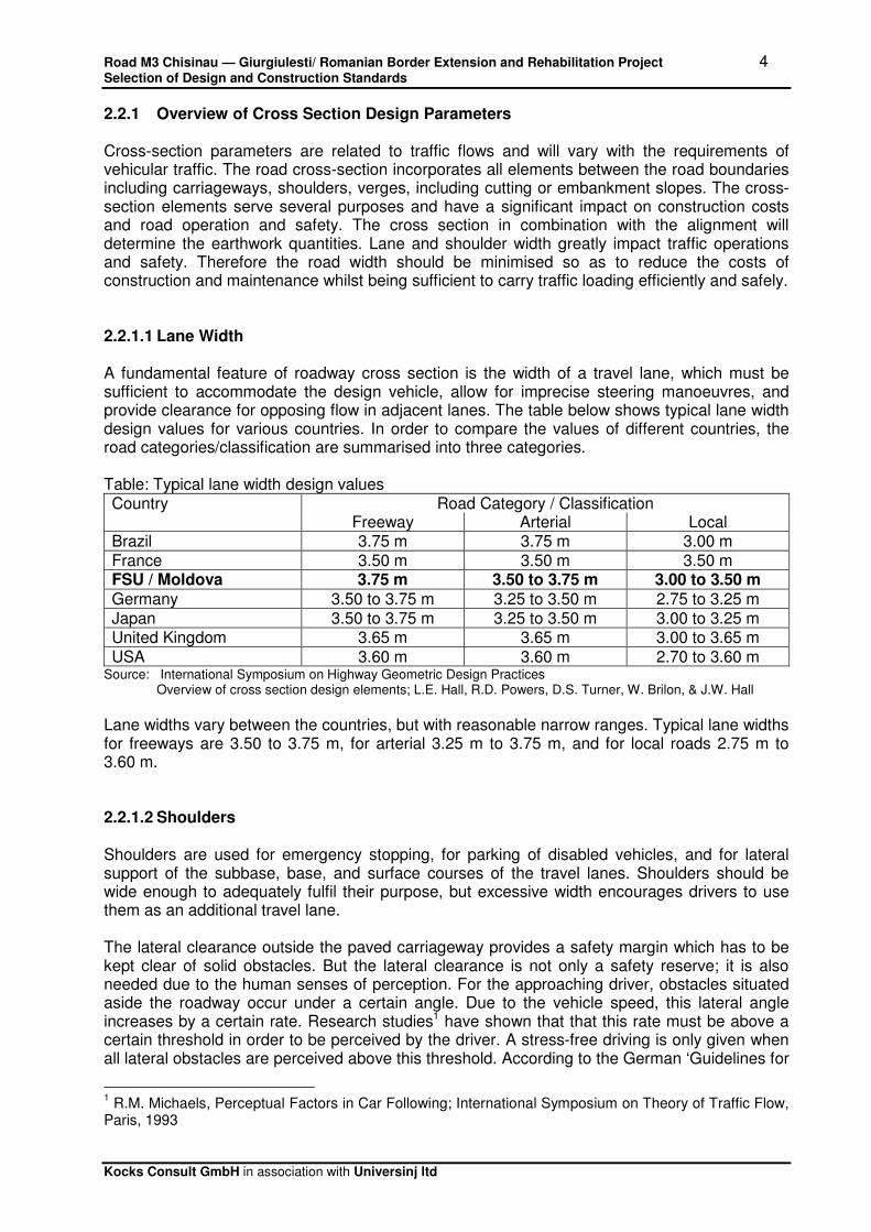
2.2.1 Overview of Cross Section Design Parameters Cross-section parameters are related to traffic flows and will vary with the requirements of vehicular traffic. The road cross-section incorporates all elements between the road boundaries including carriageways, shoulders, verges, including cutting or embankment slopes. The cross-section elements serve several purposes and have a significant impact on construction costs and road operation and safety. The cross section in combination with the alignment will determine the earthwork quantities. Lane and shoulder width greatly impact traffic operations and safety. Therefore the road width should be minimised so as to reduce the costs of construction and maintenance whilst being sufficient to carry traffic loading efficiently and safely. 2.2.1.1 Lane Width A fundamental feature of roadway cross section is the width of a travel lane, which must be sufficient to accommodate the design vehicle, allow for imprecise steering manoeuvres, and provide clearance for opposing flow in adjacent lanes. The table below shows typical lane width design values for various countries. In order to compare the values of different countries, the road categories/classification are summarised into three categories. Table: Typical lane width design values Country Road Category / Classification Freeway Arterial Local Brazil 3.75 m 3.75 m 3.00 m France 3.50 m 3.50 m 3.50 m FSU / Moldova 3.75 m 3.50 to 3.75 m 3.00 to 3.50 m
Germany 3.50 to 3.75 m 3.25 to 3.50 m 2.75 to 3.25 m Japan 3.50 to 3.75 m 3.25 to 3.50 m 3.00 to 3.25 m United Kingdom 3.65 m 3.65 m 3.00 to 3.65 m USA 3.60 m 3.60 m 2.70 to 3.60 m
Source: International Symposium on Highway Geometric Design Practices Overview of cross section design elements; L.E. Hall, R.D. Powers, D.S. Turner, W. Brilon, & J.W. Hall
Lane widths vary between the countries, but with reasonable narrow ranges. Typical lane widths for freeways are 3.50 to 3.75 m, for arterial 3.25 m to 3.75 m, and for local roads 2.75 m to 3.60 m. 2.2.1.2 Shoulders Shoulders are used for emergency stopping, for parking of disabled vehicles, and for lateral support of the subbase, base, and surface courses of the travel lanes. Shoulders should be wide enough to adequately fulfil their purpose, but excessive width encourages drivers to use them as an additional travel lane. The lateral clearance outside the paved carriageway provides a safety margin which has to be kept clear of solid obstacles. But the lateral clearance is not only a safety reserve; it is also needed due to the human senses of perception. For the approaching driver, obstacles situated aside the roadway occur under a certain angle. Due to the vehicle speed, this lateral angle increases by a certain rate. Research studies1 have shown that that this rate must be above a certain threshold in order to be perceived by the driver. A stress-free driving is only given when all lateral obstacles are perceived above this threshold. According to the German ‘Guidelines for
1 R.M. Michaels, Perceptual Factors in Car Following; International Symposium on Theory of Traffic Flow,
Paris, 1993

Road M3 Chisinau — Giurgiulesti/ Romanian Border Extension and Rehabilitation Project 5 Selection of Design and Construction Standards
Kocks Consult GmbH in association with Universinj ltd
Cross Sections’2 the relations between allowed maximum speed and minimum lateral clearance are as follows: Table: Relations between maximum speed and minimum lateral clearance according RAS-Q
Maximum allowed speed Minimum lateral clearance ≤ 50 km/h 0.75 m ≤ 70 km/h 1.00 m > 70 km/h 1.25 m
Source: RAS-Q, Richtlinien fuer die Anlage von Strassen, Teil Querschnitte, 1982
Typical shoulder width design values for selected countries presented in the table below. Table: Typical shoulder width design values Country Road Category / Classification Freeway Arterial Local Brazil 3.00 m 3.50 m 1.50 to 2.50 m France 3.00 m
+ 0.75 m unpaved 2.50 m
+ 0.75 m unpaved 2.50 m
+ 0.75 m unpaved FSU / Moldova 0.75 m
+ 3.00 m unpaved 0.50 to 0.75 m
+2.0 to 3.0 m unpaved 0.50 m
+1.5 to 2.0 m unpaved
Germany 2.50 m + 1.50 m unpaved
0.25 m + 1.50 m unpaved
0.25 m + 1.50 m unpaved
Japan > 2.50 m > 1.75 m > 0.50 m United Kingdom 3.30 m 1.00 m no shoulders USA 3.00 to 3.60 m 1.20 to 2.40 m 0.60 to 2.40 m
Source: International Symposium on Highway Geometric Design Practices Overview of cross section design elements; L.E. Hall, R.D. Powers, D.S. Turner, W. Brilon, & J.W. Hall
There is no international consensus on appropriate shoulder width. However, it should be noted that shoulders in Moldova are in comparison with western standards wider and unpaved. Road category I and II have shoulder width of 3.75 m, whereas lower road categories have 1.75 m – 2.50 m shoulders. Roads with even moderate traffic volumes do need shoulders, especially if there a high occurrence of disabled vehicles, but it is recommended to pave the shoulders in a recent width in order to provide for emergency parking and support of the road pavement. 2.2.1.3 Cross Slope A cross slope is used on traffic lanes to promote drainage of surface water. Divided highways can be treated as two separate roadways. The table below contains typical values of standard lane cross slope. Table: Typical lane slope design values Country Road Category / Classification Freeway Arterial Local Brazil 2.0 % concrete
2.5 % asphalt 2.0 % concrete 2.5 % asphalt
2.0 % concrete 2.5 % asphalt
France 2.5 % 2.5 % 2.5 % FSU / Moldova 1.5 to 2.5 % 1.5 to 2.0 % 1.5 to 2.0 %
Germany 2.5 % 2.5 % 2.5 % Japan 2.0 % 1.5 to 2.0 % 1.5 to 2.0 % United Kingdom 2.5 % 2.5 % 2.5 % USA 1.5 to 2.0 % 1.5 to 3.0 % 1.5 to 6.0 %
2 RAS-Q, Richtlinien fuer die Anlage von Strassen, Teil Querschnitte, 1982
Road M3 Chisinau — Giurgiulesti/ Romanian Border Extension and Rehabilitation Project 6 Selection of Design and Construction Standards
Kocks Consult GmbH in association with Universinj ltd
Source: International Symposium on Highway Geometric Design Practices Overview of cross section design elements; L.E. Hall, R.D. Powers, D.S. Turner, W. Brilon, & J.W. Hall
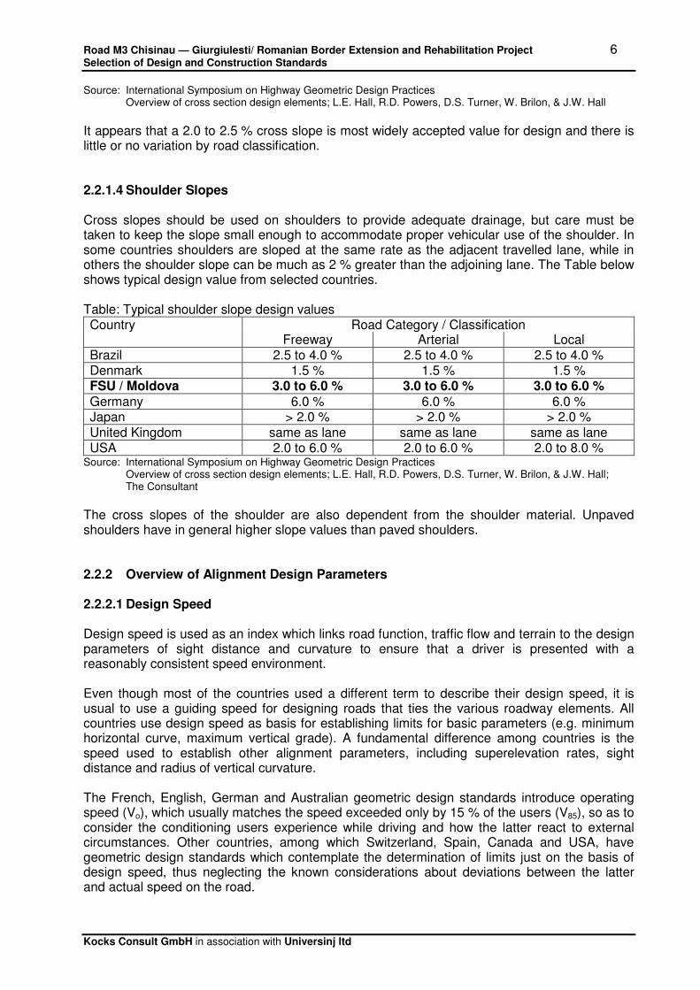
It appears that a 2.0 to 2.5 % cross slope is most widely accepted value for design and there is little or no variation by road classification. 2.2.1.4 Shoulder Slopes Cross slopes should be used on shoulders to provide adequate drainage, but care must be taken to keep the slope small enough to accommodate proper vehicular use of the shoulder. In some countries shoulders are sloped at the same rate as the adjacent travelled lane, while in others the shoulder slope can be much as 2 % greater than the adjoining lane. The Table below shows typical design value from selected countries. Table: Typical shoulder slope design values Country Road Category / Classification Freeway Arterial Local Brazil 2.5 to 4.0 % 2.5 to 4.0 % 2.5 to 4.0 % Denmark 1.5 % 1.5 % 1.5 % FSU / Moldova 3.0 to 6.0 % 3.0 to 6.0 % 3.0 to 6.0 %
Germany 6.0 % 6.0 % 6.0 % Japan > 2.0 % > 2.0 % > 2.0 % United Kingdom same as lane same as lane same as lane USA 2.0 to 6.0 % 2.0 to 6.0 % 2.0 to 8.0 %
Source: International Symposium on Highway Geometric Design Practices Overview of cross section design elements; L.E. Hall, R.D. Powers, D.S. Turner, W. Brilon, & J.W. Hall; The Consultant
The cross slopes of the shoulder are also dependent from the shoulder material. Unpaved shoulders have in general higher slope values than paved shoulders. 2.2.2 Overview of Alignment Design Parameters 2.2.2.1 Design Speed Design speed is used as an index which links road function, traffic flow and terrain to the design parameters of sight distance and curvature to ensure that a driver is presented with a reasonably consistent speed environment. Even though most of the countries used a different term to describe their design speed, it is usual to use a guiding speed for designing roads that ties the various roadway elements. All countries use design speed as basis for establishing limits for basic parameters (e.g. minimum horizontal curve, maximum vertical grade). A fundamental difference among countries is the speed used to establish other alignment parameters, including superelevation rates, sight distance and radius of vertical curvature. The French, English, German and Australian geometric design standards introduce operating speed (Vo), which usually matches the speed exceeded only by 15 % of the users (V85), so as to consider the conditioning users experience while driving and how the latter react to external circumstances. Other countries, among which Switzerland, Spain, Canada and USA, have geometric design standards which contemplate the determination of limits just on the basis of design speed, thus neglecting the known considerations about deviations between the latter and actual speed on the road.

Road M3 Chisinau — Giurgiulesti/ Romanian Border Extension and Rehabilitation Project 7 Selection of Design and Construction Standards
Kocks Consult GmbH in association with Universinj ltd
The following synoptic chart shows how design speed (VP) and operating speed (Vo) have a part in the geometric design of selected countries. Table: Dimensioning of the elements of the road depending on speed Country Horizontal Elements Vertical Elements RH A DS1 DS2 Q Igrade RV,sag RV,crest Australia Vo Vo Vo Vo Vo Vo Vo Vo Canada VP VP VP VP VP VP VP VP FSU / Moldova VP VP VP VP VP VP VP VP Germany VP VP Vo Vo Vo VP VP VP United Kingdom Vo Vo Vo Vo Vo - Vo Vo USA VP VP VP VP VP VP VP VP
Source: An Experimental Investigation on the Relationship between Speed and Road Geometry, A.Bevilacqua, G.DiMino, J.Nigrelli & The Consultant
Note: RH – horizontal radius A – parameter of transition curve DS1 – stopping sight distance DS2 – passing sight distance Q – superelevation rate Igrade – gradient slope RV,sag – radius of sag curve RV,crest – radius of crest curve “ – “ indicates an element independent of speed The establishment of operating speed backgrounds is an important assumption that must be regarded when establishing modern highway geometric design guidelines. Nowadays, a speed parameter capable of better interpreting users’ behaviour is more and more used, thus replacing the traditional design speed. Therefore the operating speed is the more modern parameter of the design speed definition for dimensioning of horizontal and vertical alignment elements. Due to the different approach in defining the design speed, values for individual alignment parameters must be evaluated within the context of a country overall design policy, which demands considerable care in making comparison. 2.2.2.2 Horizontal Curvature The table below summarizes the minimum radius of horizontal curvatures as a function of design speed for various countries. These values are a product of maximum superelevation rates and maximum coefficients of side friction. It should be noted that in mountainous terrain reduced values for horizontal curves are provided in certain design standards. Table: Minimum radius of horizontal curves
Design Speed
Minimum Radius (m) of Horizontal Curves
(km/h) Australia France FSU/Moldova Germany Japan UK USA 50 45 100 100 127 80 60 70 120 150 135 150 180 125 70 95 200 255 175 80 140 240 300 280 280 230 85 360 90 230 380 305 100 360 425 600 500 460 510 395 110 435 500 120 800 800 710 720 665
Source: International Symposium on Highway Geometric Design Practices & Worldwide review of alignment design policies; R.A. Krammes & M.A. Garnham

Road M3 Chisinau — Giurgiulesti/ Romanian Border Extension and Rehabilitation Project 8 Selection of Design and Construction Standards
Kocks Consult GmbH in association with Universinj ltd
Minimum radius of horizontal curvature for a given design speed varies considerable among countries. This range results from differences in maximum superelevation rates and maximum side friction coefficients. 2.2.2.3 Maximum Gradient Maximum gradient guidelines range in complexity, with various countries considering some or all of the following factors: road classification, design speed and terrain. For example in the UK, desirable maximum gradient values are specified for road types: motorway (3 %), dual carriageway (4 %), and single carriageway (6 %). In Switzerland, maximum gradient is a function of design speed (from 10 % for a 60 km/h to 4 % for 120 km/h design speed). In Germany, maximum gradient is a function of road type and design speed. For main rural roads values range from 8 % for 60 km/h to 4 % for 120 km/h design speed. In the USA maximum gradients are based upon road type, topography and design speed. The FSU standard for the maximum gradient is dependent on the design speed, and ranges from 4 % for 120 km/h design speed to 10 % for 30 km/h design speed. Usually gradients in more rolling and mountainous terrain may be 1 to 2 % steeper, particularly where traffic volumes are at the lower end of the range. 2.2.2.4 Minimum Radius of Crest (Convex) Vertical Curves Minimum radii of crest curves are established to satisfy stopping sight distance requirements, whereas most of the countries specify the use of parabolic vertical curves. According to AASHTO the radius corresponds to the K-value, or rate of vertical curvature which is used in several countries. The design is based on minimum allowable ‘K-values’, as defined by the formula:
K =L/A
Where K = rate of vertical curvature per change in grade given as meters per percent grade change
L = Minimum length of vertical curve A = algebraic difference in approach and exist grades (%)
In order to compare values for vertical curves, the AASHTO ‘K-values’ have been converted to the approximate corresponding radii values. Minimum radii for various design speeds of selected countries are presented in the table below.
Table: Minimum radius of crest curves Design Speed
Minimum Radius (m) of Crest Curves
(km/h) Australia France FSU/Moldova Germany Japan UK USA 50 540 1,500 800 1,100 1,000 60 920 1,500 2,500 2,700 1,400 1,900 1,800 70 1,570 3,500 3,300 3,100 80 2,400 3,000 5,000 5,000 3,000 4,900 85 5,900 90 4,200 7,000 7,100 100 6,300 6,000 10,000 10,000 6,500 10,500 10,500 110 9,500 15,100 120 13,500 10,000 15,000 20,000 11,000 18,500 20,200
Source: International Symposium on Highway Geometric Design Practices & Worldwide review of alignment design policies; R.A. Krammes & M.A. Garnham

Road M3 Chisinau — Giurgiulesti/ Romanian Border Extension and Rehabilitation Project 9 Selection of Design and Construction Standards
Kocks Consult GmbH in association with Universinj ltd
2.2.2.5 Minimum Radius of Sag (Concave) Vertical Curves Sag vertical curves are generally considered as less critical from the safety point of view than crest curves. Several countries base their values for minimum sag curves on headlight illumination distances to satisfy stopping sight distance requirements on unlit roadways at night. Other countries base their design values on driver comfort. In Germany, the minimum radius of sag curves is one half the minimum radius of crest curves art a given design speed. Minimum radii of sag curves for various design speeds of selected countries are presented in the table below. Table: Minimum radius of sag curves
Design Speed
Minimum Radius (m) of Sag Curves
(km/h) Australia France FSU/Moldova Germany Japan UK USA 50 1,200 700 1,300 1,200 60 600 1,500 1,500 1,500 1,000 2,000 1,800 70 2,000 2,000 2,500 80 1,000 2,200 2,000 2,500 2,000 3,200 85 2,000 90 3,500 4,000 100 1,600 3,000 3,000 5,000 3,000 2,600 5,100 110 6,200 120 2,300 4,200 5,000 10,000 4,000 3,700 7,300
Source: International Symposium on Highway Geometric Design Practices Worldwide review of alignment design policies; R.A. Krammes & M.A. Garnham
Note: In order to compare values for vertical curves, the AASHTO ‘K-values’ have been converted to the approximate corresponding radii values.
It should be noted that SNIP allows to use reduced radii of sag curves in mountainous terrain, but for comparison of the values these are not considered. 2.3 Recommendation for Application of Geometric Design Standards Designs should be justified economically, and the optimum choice will vary with both construction and road user costs. Construction costs will be related to terrain type and choice of pavement construction, whereas road user costs will be related to level and composition of traffic, journey time, vehicle operation and road accident costs. Currently, the geometric road design standards in Moldova are those which were used throughout the former Soviet Union. Since the last edition of the SNIP for road design was introduced in 1984, this standard is not in keeping with the times, and modern developments and practices are not considered. Design speeds and the resulting geometric road characteristics according SNIP are slightly higher than in Western Europe or North America for certain parameters. This indicated a lesser consideration given to economic justification at the design stage and makes these standards expensive. Drainage, traffic safety, and continuity of road design are not explicit considerations in the SNIP design standard, which leads to inappropriate design solutions. The shortcomings of the current geometric standards are apparent on the project roads and due to inadequate maintenance the effects are getting worse. In particular the lack of drainage has resulted in excessive potholing, leading to a complete destruction of the existing pavement.

Road M3 Chisinau — Giurgiulesti/ Romanian Border Extension and Rehabilitation Project 10 Selection of Design and Construction Standards
Kocks Consult GmbH in association with Universinj ltd
Within this Project we recommend that the design standards and constructions that will be applied, shall correspond to the representative international standards, for the geometrical elements, for pavement, drainage and traffic structures. The Consultant proposes the revision of the current design standards and norms, with special reference to the international standards, economic feasibility and construction costs. If it will be necessary, it will be recommended the use of the international design standards from countries with similar climate conditions for certain design condition. This will be carried out in close cooperation with the Client to ensure support and approval. Feasibility Study Recommendations „Road M3 Chisinau-Giurgiulesti/Romanian Border Extension and Rehabilitation Project” will follow where it is possible, on the existent alignment to minimize the excessive digging, new agriculture land acquisition, demolishing, and realignment of the road on the difficult damaged sections and in urban areas. Resulting from the above mentioned, and taking into account the specific conditions of every road section, in the table below are proposed the following parameters for carriageway and shoulders: Table: Proposed roadway and shoulder width
Existent road sections Paved Roadway
Width (1)
Gravel Shoulder Width (2)
(m) (m)
Chişinău- Porumbrei
15.0+(2x0,75+2x1,0) Existent
Porumbrei-Valea Perjei, (intersection withR 3) 8,0 1,0 intersection with R 3 – Cimislia (coincides with R3 Chişinău-Hînceşti-Cimişlia-Basarabeasca)
8.0 1,0
Cimişlia -Comrat 8.0 1,0
Comrat -Ciumai 8.0 1,0
Ciumai –st. Vulcaneşti (bypass section Ciumai - Burlăceni - st. Vulcaneşti)
8.0 0,5
st. Vulcaneşti- Vulcaneşti town 8.0 0,5
Vulcaneşti town - Giurgiuleşti 8.0 0,5
Notes: (1) Including width of paved shoulder (2) Where existing roadbed is insufficient, shoulders could be narrower
2.4 Relaxation of Standards The proposed design values of the geometric design standards are usually intended to provide guidance for the design rather than to be considered as rigid minima. It should be realized that information and values presented in the design guidelines is considered as a ‘design standard’, but more appropriately described as good engineering practice that should be strived to achieve. But the justification for construction of a particular road will always be based on a detailed technical and economic appraisal, and relaxations of standards may be essential in order to achieve an acceptable level of return on investment. However, safety implication of a substandard road section needs serious consideration. Experience in the UK3 has shown that reduction of design parameters by one design class step, equivalent to a 15 % speed reduction, is likely to have little effect on safety. A relaxation of two
3 Overseas Road Note 6, A guide to geometric design, Overseas Unit Transport and Road Research
Laboratory, UK, 1988

Road M3 Chisinau — Giurgiulesti/ Romanian Border Extension and Rehabilitation Project 11 Selection of Design and Construction Standards
Kocks Consult GmbH in association with Universinj ltd
steps, equivalent two a 30 % speed reduction, should not significantly increase risks where appropriate signing and/or other warning measures are provided. High speeds on rural roads are also a safety issue and attempts are ongoing to control and reduce speeds. A study on speed, speed limits and accidents4 concluded that a reduction of 1.6 km/h (1 mph) in the average speed reduces the incidence of injuries by about 5%. To achieve this objective, higher speeds are scarified to preserve safety. A common approach for improving safety on these roads is the use of narrower lane width, which requires drivers to slow down. 3. Pavement Design Standards Prior to the review and selection of standards for the road pavement design the general design principles, design philosophies and parameters are listed which form the base criteria for all major design standards. 3.1 General design principles Pavement design is a process of selection of appropriate pavement and surfacing materials to ensure that the pavement performs adequately and requires minimal maintenance under the anticipated traffic loading for the design period adopted. This selection process involves adoption of material types, thicknesses and configurations of the pavement layers to meet the design objectives. Performance objectives are to:
� provide safe and comfortable riding conditions to all road users, being motor vehicles, cyclists and pedestrians, optimised for the road’s intended function and the level of use;
� provide low cost of ownership (ie minimum whole of life cost) to the State Road
Authorities (Government);
� comply with the Pavement Standards and other relevant State Road Authorities’ Guidelines and/or Standards.
3.2 Pavement types The Pavement Design Standards set out procedures for the design of the following pavement types:
• flexible pavements consisting of granular pavement materials with thin bituminous surfacing (“granular pavements”);
• flexible pavements that include one or more lightly bound layers, either in situ or in a plant (“stabilised pavements”);
• flexible pavements consisting of predominantly asphalt concrete layers;
• rigid pavements (“concrete pavements”).
4 Speed, Speed Limits and Accidents, D.J.Finch, PR58, Transportation Research Laboratory, 1994

Road M3 Chisinau — Giurgiulesti/ Romanian Border Extension and Rehabilitation Project 12 Selection of Design and Construction Standards
Kocks Consult GmbH in association with Universinj ltd
Flexible pavements consisting of granular pavement materials without dust free surfacing (“gravel pavements”) should be considered only for remote rural roads, minor access roads or temporary roads. 3.3 Design Parameters When designing or selecting pavement, there are three fundamental external design parameters to consider:
• the characteristic of the subgrade upon which the pavement is placed,
• the applied loads and
• the environment. The basic input data for pavement design are design life to be specified, the traffic to be carried and the strength of the subgrade. Design life: Design life is defined in terms of the cumulative traffic that can be carried before strengthening of the pavement is necessary. In this context, design life does not mean that at the end of the period the pavement will be completely worn out and in need of reconstruction; it means that towards the end of the period the pavement will need to be strengthened so that it can continue to carry traffic satisfactorily for a further period. Traffic: The traffic loads are expressed in terms of accumulated equivalent standard axle loads (ESAL) per direction, passing the road during the scheduled design life. Subgrade strength: The strength of road subgrade is commonly assessed in terms of the California Bearing Ratio (CBR) and this is dependent on the type of soil, its density, and its moisture content. 3.4 Discussion and review of pavement design standards For the pavement design of the project road the selection of standards has been limited to standards which have been proposed by the Client or have been used before in Moldova. These are the Russian/Former Soviet Union standards. The European Standards were not introduced officially and at the moment they are not applied in road design. Further we will present a short comparative description of the international standards representative with the pavement design standard used in Republic of Moldova. United Kingdom The relevant standard for the design and construction of roads in the UK is the ‘Design Manual for Roads and Bridges (DMRB, Feb.2006)’. For the assessment of the foundation and the design of the pavement structure Volume 7, ‘Pavement Design and Maintenance’ of the manual has to be used. It is an analytically based calculation method which has her origins in the year 1984. The basis for the calculation forms a multi layer model. Results of empirical studies have been analysed and included to form an analytical-empirical design approach. In the analytical-empirical design method stresses and strains in the pavement are calculated by means of mathematical models and allowable stresses and strain are found from laboratory tests on materials combined with in situ observations/calibrations.
Road M3 Chisinau — Giurgiulesti/ Romanian Border Extension and Rehabilitation Project 13 Selection of Design and Construction Standards
Kocks Consult GmbH in association with Universinj ltd
The difficult but very important part of this analytical-empirical design methodology is the verification with in-situ conditions. Russia /Former Soviet Union (FSU) Russian Standards/FSU for the design of the pavement are the „Instructions for Design of flexible road pavements, VSN 46-83”. This norm is still used in Moldova, even if in Russia is cancelled since 2001 and replaced by the norm „ODN 218.046-01 Non-rigid road systems design”. In the design practice of the non-rigid road systems, the local designers are using ODN 218.046-01, and the results of application of this standard shows that the road complex calculated according to the last instruction, results with a smaller load capacity than with VSN 46-83 for the same calculation conditions (traffic, thickness of pavement layers, type of earth at the road base). To ensure the necessary load capacity, (modulus of elasticity E) from calculation ODN 218.046-01 results a road system with a bigger total thickness comparing to the VSN result. This Russian Design Method is an Analytical Design method, where Stresses and strains are calculated from mathematical models and then compared with design criteria. In many respects the Russian method is taking into considerations much more variables than any western design methodology, and in that respect is much more fundamental. The governing factor for pavement design is the so-called stiffness modulus of the pavement structure. The stiffness modulus is calculated under consideration of E-moduli of the respective pavement layers. The weak point of the method is however that the foundation support (the subgrade) is based on definition of subgrade type only (without any further verification on site), and not on measurable in situ values of the subgrade. The Russian/FSU design procedure is a method using theoretical material values. Although an adequate stiffness of a road structure is an important requirement, this does not necessarily translate into a well designed pavement, comfortable to use and economic in construction and maintenance. USA The major influence on design methods in the USA and even worldwide has the design method developed by the ‘American Association of State Highway and Transportation Officials’ (AASHTO). This design method the ‘AASHTO Guide for Design of Pavement Structures’ is taken here as representing the USA. The AASHTO Design Method is an empirical method and empirical equations have been built into the design method. Major factors are the time of use until first maintenance is required, the reliability and the structural number (layer coefficient) of the pavement layers. For the subgrade the relevant material parameter the E-module is determined by laboratory tests on representative samples or calculated from FWD tests. In the AASHTO design beside the E-module the layer coefficients are basic characteristics of the pavement materials which are required for the dimensioning of the pavement layers based on the structural number. Relations between CBR value and layer coefficient are shown in diagrams or can be calculated using simple equations. Different drainage conditions are taken into consideration by modified layer coefficients. The final pavement design and dimensioning is done using design charts and monographs.

Road M3 Chisinau — Giurgiulesti/ Romanian Border Extension and Rehabilitation Project 14 Selection of Design and Construction Standards
Kocks Consult GmbH in association with Universinj ltd
3.5 Assessment of Pavement Design Standards and Recommendations The design method used in the Russian/FSU standards is a theoretical procedure. Especially the practice using the stiffness modulus and the tensile strength at the bottom of the asphalt layers does not take into consideration the actual subgrade conditions. The subgrade strength or bearing capacity is taken from researches which specify general values and no in-situ verification is required. The criterion for determination of asphalt layer thickness is the limit on the tensile strength at the bottom of the asphalt layer. In European standards the pavement design is based on tolerable stresses induced in the subgrade by traffic load. The different subgrade materials and their behaviour are considered with the respective subgrade bearing capacity (e.g. CBR, plate load test) leading to the total pavement thickness. The total pavement thicknesses result from standardised pavement layer thicknesses which have been empirically determined. In addition the materials requirements are specified and have to be verified on site by regular testing to ensure the required bearing capacity of each layer. The criteria for determination of asphalt layer thickness is to provide a satisfactory service over the planned design life period of the pavement, taking into consideration the effects (climate, traffic) on the road surface. The American pavement design standard is similar to the European standards based on tolerable stresses in the subgrade. The relevant bearing capacity is determined by in-situ and laboratory testing. The total pavement thickness results from standardised layer thicknesses based on a number of parameters which are the result of empirical studies and experience. It is recommended to use a pavement design method more based on values of experience and empirical studies than a pure theoretical design approach where hardly all relevant parameters for variable actual conditions can be included. The Russian/FSU standard has its weak point in not verifying the in-situ subgrade condition and dimensioning is based on the tensile strength at the bottom of the asphalt layer not the actual subgrade strength. The AASHTO design standard, representing the USA standards, is an empirical design method using a number of variable parameters of which some may be subject to the designer’s assessment as not for all countries specific recommendations or guidelines are existing. The UK pavement design standard (representing the European standards) has developed into an analytical-empirical design method. This design method combines the advantages of the theoretical (Russian/FSU) and empirical (USA/AASHTO) pavement design methods. The actual version issued in February 2006 includes the latest level of knowledge derived from theoretical research und empirical studies. Summarising the above it is recommended from the technical point of view to use the UK pavement design standard „Design Manual for Roads and Bridges, HD 26/06“ for the M3 Road Chisinau – Giurgiulesti/Romanian Border Extension and Rehabilitation project. 4. Bridge Design Standards 4.1 Bridge Design Standards in Moldova The bridge design standard in Moldova is based on the former Soviet Union standards. All structures are classified in classes of bridges according to the standards valid during the time of their design/construction. Bridges are divided into classes according design loads. The design load requirements changed over the years to follow the technical development of trucks. Standard truck loads have increased from 18 t to 30 t and heavy loads from 60 t to 80 t.

Road M3 Chisinau — Giurgiulesti/ Romanian Border Extension and Rehabilitation Project 15 Selection of Design and Construction Standards
Kocks Consult GmbH in association with Universinj ltd
Table: Design load Year Design Standard Road Category I, II Road Category III - V
Truck Overweight load Truck Overweight load
1943 - 1953 SNIP 11 N 13 NK 60 N 10 NG 60
1953 – 1962 SNIP 11-A.8-54 N 18 NK 60 N 13 NK 60
1962 – 1984 SNIP 11-A.7-62 N 30 NK 80 N 30 NK 80
Since 1984 SNIP 2-05.03-84 A 11 NK 80 Road cat. III: A 11
Road cat. IV - V: A 8
NK 80
NK 60
The load N 18 is a truck of 18 t with two axles (distance between the axles 4.00 m). The distance between the back axle of the first truck and the front axle of the next truck is 10 m. The load N 30 is a truck of 30 t with 3 axles. The truck has a front axle of 6 t, after a space of 6 m a second axle of 12 t and a third axle of 12 t at a distance of 1.6 m after the second axle. The distance between the back axle of the first truck and the front axle of the next truck is 10 m. The load A 11 is a uniform load includes - one 2-axle truck with a weight of 11 t - a uniform load on spans (0.1 x 11 t) t/m For road category IV and V and local roads the A load is reduced to 8 t and called A 8. The overweight load NK 80 is composed of four single axle loads of 20 t each, total weight 80 t, with 1.20 m distance between the axles. The overweight load NK 60 is designed for A 8 load. This load of 60 t is distributed from a tracked vehicle of 5 m length and 3.30 m width, wheel width 0.70 m. 4.2 Review of existing Bridge Design Standard For detail assessment of the bridge classes and their bearing capacity respectively a comparison with a western European standard was made. For this purpose the German standard DIN 1072 was used and the relevant data are summarised in the table below. Table : Bending moments
Span Bending Moments (KNM) (meter) Germany
Cl. 60/30 (DIN 1072) only main
lane
Germany Cl. 60/30
(DIN 1072) carriageway
width 7m
Germany Cl. 30/30
(DIN 1072) only main
lane
Germany Cl. 30/30
(DIN 1072) carriageway
width 7m
FSU SNIP
2.05.03-84 NK-80
FSU SNIP
2.05.03-84 NG-60
5 612.0 846.4 306.0 504.4 520.0 375.0
10 1,623.0 2,279.1 891.0 1,487.1 1,520.0 1,125.0
15 2,690.0 3,841.0 1,442.4 2,592.9 2,520.0 1,875.0
20 3,794.0 5,524.2 2,129.7 3,850.2 3,520.0 2,625.0
25 4,952.0 7,318.0 2,882.3 5,247.8 4,520.0 3,375.0
30 6,125.0 9,210.0 3,688.8 6,774.3 5,520.0 4,125.0
The bending moments from the loads of the main lane of the bridge classes 60/30 and 30/30 of DIN 1072 as well as the bending moments from the loads of the bridge deck with a width of 7 m of the bridge classes 60/30 and 30/30 of DIN 1072 were analysed, as well as the bending moments of the bridge classes NK-80 and NG-60 corresponding to SNIP standard 2.05.03-84.

Road M3 Chisinau — Giurgiulesti/ Romanian Border Extension and Rehabilitation Project 16 Selection of Design and Construction Standards
Kocks Consult GmbH in association with Universinj ltd
A comparison of the results shows that the bridge classes NK-60 corresponds nearly to the bridge class 30/30 according to DIN 1072. Structures which can be classified into this or a higher class of bearing capacity comply with present bridge requirements as far as the bearing capacity is concerned. However, the review and comparison of SNIP with the German standard DIN: (a) Contrary to DIN for reinforced and pre-stressed concrete (safety factors 1.75 generally)
SNIP is based on a partial safety concept. In iteration comparison of the opposing concepts can estimated by multiplication of load with material safety factors. The bending reinforcement is calculated to SNIP for dead load at 1.1x1.15=1.27, for total load 1.5x1.15=1.73, for 30 t truck groups 1.4x1.15=1.61, and for the 80 t heavy goods vehicle (HGV) 1.1x1.15=1.27. With the HGV applicable for short spans, the highest applicable safety factor is approx, 1.3.
(b) the safety concept provided by SNIP is substantially lower than provided by DIN. This
applies also to the comparison calculation done in accordance with the British Standard BS (as carried out under a separate technical assistance project financed by TACIS), for the British standard HA- and HB traffic loads.
(c) The small difference between working loads and ultimate loads implies that the dynamic
cyclic loading component is relatively larger than the yield point strength load of the reinforcement, increasing fatigue of the reinforcement. In this connection it is important to note that pre-cast bridge deck elements are made using welded reinforcement cages.
4.3 Structural Principles according to Standard Drawings The standard drawings for pre-cast slab bridges (spans of 6 – 9m) and for pre-cast slab-beam-bridges (spans of 12, 15 and 18 m) revealed the structural principles of these bridges insofar as being relevant to the appropriate designs of rehabilitation measures suggest for the project. The structural principles are: (a) Reinforcement made of welded (part-) cages in mats, where horizontal lower and upper
mats do not seem to be welded onto the stirrup, and were anchors as solely provided by the welded joints
(b) Pre-cast elements are bedded on mortar only on the capping beams, fixed with grouted
dowels, with additional concrete stops in transverse direction (c) Pre-cast superstructure elements are shear profiled along longitudinal joints, and
according to the drawing filled with concrete for providing transverse distribution of wheel loads onto adjacent pre-cast slabs.
(d) Transverse joints are without continuation plates, but only with hooks for the sealing,
continued asphalt layer, (e) Capping beams in situ concrete or as precast elements; precast parts are welded to
piles and jointed to the beams by penetration pockets to be closed finally with concrete/mortar
(f) The details provided for bridges equipment (side walks, sealing, drainage, bearings,
joints etc.) are not comparable to international standard, and have been identified as major causes for damages. Improvement is required to avoid continued deterioration.

Road M3 Chisinau — Giurgiulesti/ Romanian Border Extension and Rehabilitation Project 17 Selection of Design and Construction Standards
Kocks Consult GmbH in association with Universinj ltd
4.4 Assessment of Bridge Design Standards and Recommendations The assessment concludes that construction in accordance with SNIP and the typical drawings does not provide from the technical point of view bridges in satisfactory quality compared with today’s accepted state-of-the-art standards, which provides long service life. This is even more important when noting that the minimal structural requirements were often not observed during construction. Considering that international standards specify the latest state-of-the-art in terms of concrete technology and reinforcement arrangement, an advanced standard should be considered for reason of extended service life and reduced maintenance and repair costs. The German standard DIN specifications are equivalent to other international standards such as British BS 5400 Part7 and 8 (Steel, Concrete and Composite Bridges), or equivalent. To be in line with the other design standards it is therefore recommended to use also British bridge design standards. 5. Construction Standards The construction standards lays down the quality of materials, the standards of workmanship, the testing methods and the acceptance criteria for civil engineering works. Since it is envisaged to carry out the design of road and structures according to British standard also the construction standard should follow British standard. To use the same standards as in the design is also essential, due to the inter-relationship between design and construction standards. Structural parameter for pavement and structures requires material specification in accordance with the design standard used and testing procedures tailored for the designated material. Moreover, the best practices governing road and bridge construction shall been followed and every effort should been made to provide specifications that are in keeping with expected traffic demands and needs on roads. Besides the construction standards shall be also in accordance with all applicable environmental, health & safety laws and regulations. Therefore the provisions contained in modern western construction standards needs to be considered in order to reach consistency with representative international standards.

ANNEX 1
List of Major Former Soviet Union Standards Related to Roads and Bridges

The design, construction and maintenance of roads in Moldova are carried out to the provisions of various technical standards of the former Soviet Union. Major former Soviet Union technical standards related to roads and bridges are listed below. In some case FSU standards (shaded in grey)have been modified through updated Moldovan standards. SNiP Standards
SNIP Code
Title in English Title in Russian
SNiP 1.02.07-87 СниП 1.02.07-87
Engineering Survey for Construction Инженерные изыскания для строительства
SNiP ІІІ-4-80* issue 1989 СниП ІІІ-4-80* изд. 1989г
Safety measures in construction Техника безопасности в строительстве.
SNiP 2.01.01-82 СНиП 2.01.01-82
Construction Climatology and Geophysics. Строительная климатология и геофизика
SNiP 2.01.15-90 СНиП 2.01.15-90 Replaced by NCM A.06.01-2006 (MCH 2.03-01-2002)
Engineering protection of territories, houses and structures against dangerous geological processes. Main design provisions. Geological prospection, subgrade and base. Technical protection of the territory, building and constructions against dangerous geological processes. General data (Agency of Construction and Development of the Territory in Republic of Moldova)
Инженерная защита территорий, зданий и сооружений от опасных геологических процессов. Основные положения проектирования
SNiP 2.05.02-85 СНиП 2.05.02-85
Automobile Roads Автомобильные Дороги
SNiP 2.06.15-85 СНиП 2.06.15-85
Engineering protection of territories against flooding and under-flooding.
Инженерная защита территорий от затопления и подтопления.
SNiP ІІ-7-81* issue 1991 СНиП ІІ-7-81* изд. 1991г Replaced by NCM F.03.02-2005
Construction in seismic regions. Designing the buildings with masonry walls (Agency of Construction and Development of the Territory in Republic of Moldova)
Строительство в сейсмических районах. Проектирование зданий с каменными стенами
SNiP ІІ-12-77 СНиП ІІ-12-77 Replaced by NCM D.03.01-2006(2.04-03-2005)
Noise protection Noise protection (Agency of Construction and Development of the Territory in Republic of Moldova)
Защита от шума Защита от шума
SNiP 2.01.07-85 СНиП 2.01.07-85 Replaced by NCM E.01.02-2005
Loading and impacts. Actions in constructions. Regulations establishing the construction importance categories (Construction and Territory Development Department of Republic of Moldova)
Нагрузки и воздействия Положение об определении категории ответственности конструкции
SNiP 3.01.03-84 СНиП 3.01.03-84
Topographical works in construction. Геодезические работы в строительстве.
SNiP 2.02.01-83 СНиП 2.02.01-83
Footing (ground) of houses and structures. Основания зданий и сооружений.
SNiP 2.02.02-85 СНиП 2.02.02-85
Footing (ground) of hydraulic structures. Основания гидротехнических сооружений.
SNiP 2.02.03-85 СНиП 2.02.03-85
Pile foundations Свайные фундаменты
SNiP 2.05.03-84 СНиП 2.05.03-84
Bridges and Culverts. Мосты и трубы

SNiP 2.05.11-83 СНиП 2.05.11-83
Interfarm roads in collective farms, soviet farms and the other agricultural enterprises.
Внутрихозяйственные автомобильные дороги в колхозах, совхозах и других сельскохозяйственных предприятиях и организациях.
SNiP ІІ-44-78 СНиП ІІ-44-78
Railway and road tunnels. Тоннели железнодорожные и автодорожные
SNiP 3.06.04-91 СНиП 3.06.04-91
Bridges and Culverts. Мосты и трубы.
SNiP ІІІ-44-77 СНиП ІІІ-44-77
Railway, road and hydraulic tunnels, subways
Тоннели железнодорожные, автодорожные и гидротехнические. Метрополитены
SNiP 2.01.14-83 СНиП 2.01.14-83 Replaced by CP D.01.04-2007 (МСП 3.04-101-2005)
Calculation of the design hydrological parameters Determination of the main design hydrological parameters. (Agency of Construction and Development of the Territory in Republic of Moldova)
Определение расчётных гидрологических характеристик Определение основных расчетных гидрологических характеристик
SNiP 2.06.01-86 СНиП 2.06.01-86 Replaced by NCM D.01.03-2007
Hydraulic structures. Main provisions. Hydrological structures. Main provisions. (Agency of Construction and Development of the Territory in Republic of Moldova)
Гидротехнические сооружения. Основные положения Гидротехнические сооружения. Основные положения
SNiP 2.06.04-82* issue 1986 СНиП 2.06.04-82* изд. 1986г.
Loadings and impacts on the hydraulic structures (from waves, ice and from ships).
Нагрузки и воздействия на гидротехнические сооружения ( волновые, ледовые и от судов).
SNIP Code
Title in English Title in Russian
SNiP 2.06.07-87 СНиП 2.06.07-87
Retaining walls, ship locks, fishways, and fish protection structures
Подпорные стенки, судоходные шлюзы, рыбопропускные и рыбозащитные сооружения.
SNiP 3.07.01-85 СНиП 3.07.01-85
Hydraulic and river control structures. Гидротехнические сооружения речные.
SNiP 2.03.01-84* issue 1989 СНиП 2.03.01-84* изд. 1989г. Replaced by NCM F.02.02-2006
Concrete and reinforced concrete structures. Calculation, design and composition of the elements of reinforced concrete constructions and prestressed concrete. (Agency of Construction and Development of the Territory in Republic of Moldova)
Бетонные и железобетонные конструкции. Расчет проектирования и методика изготовления элементов из обычного и пренарпяженного железобетона
SNiP 2.03.11-85 СНиП 2.03.11-85
Protection of building structures against corrosion.
Защита строительных конструкций от коррозии.
SNiP 2.06.08-87 СНиП 2.06.08-87
Concrete and reinforced concrete members of hydraulic structures.
Бетонные и железобетонные конструкции гидротехнических сооружений.
SNiP ІІ-23-81* issue. 1990 СНиП ІІ-23-81* изд. 1990г
Steel Structures. Стальные конструкции.
SNiP 3.04.03-85 СНиП 3.04.03-85
Protection of building structures against corrosion.
Защита строительных конструкций от коррозии.
GOST Standards
GOST Code
Title in English Title in Russian
GOST 10807-78 ГОСТ 10807-78
Road signs. General specifications Знаки дорожные. Общие технические условия

GOST 16149-70 ГОСТ 16149-70
Protection of underground structures against stray current corrosion by polarized protectors. Technical requirements
Защита подземных сооружений от коррозии блуждающим током поляризованными протекторами. Технические требования
GOST 18659-81 ГОСТ 18659-81
Bitumen road emulsions. Technical requirements
Эмульсии битумные дорожные. Технические условия
GOST 23457-86 ГОСТ 23457-86
Traffic control devices. Application Технические средства организации дорожного движения. Правила применения
GOST 23740-79 ГОСТ 23740-79
Soils. Methods of laboratory determination of organic composition
Грунты. Методы лабораторного определения содержания органических веществ
GOST 23961-80 ГОСТ 23961-80
Construction, equipment and rolling stock clearance diagrams for USSR Metro
Метрополитены. Габаритные приближения строений, оборудования и подвижного состава
GOST 24143-80 ГОСТ 24143-80
Soils. Laboratory methods for determination of swelling and shrinking characteristics
Грунты. Методы лабораторного определения характеристик набухания и усадки
GOST 24451-80 ГОСТ 24451-80
Highway tunnels. Construction and equipment clearance diagrams
Тоннели автодорожные. Габариты приближения строений и оборудования
GOST 24846-81 ГОСТ 24846-81
Soils. Measuring methods of strains of structures and building bases
Грунты. Методы измерения деформаций оснований зданий и сооружений
GOST 24847-81 ГОСТ 24847-81
Soils. Determination methods of seasonable depth of freezing
Грунты. Методы определения глубины сезонного промерзания
GOST 25358-82 ГОСТ 25358-82
Soils. Field method of determining temperature
Грунты. Метод полевого определения температуры
GOST 25584-90 ГОСТ 25584-90
Soils. Laboratory methods for the determination of a filtration factor
Грунты. Методы лабораторного определения коэффициента фильтрации
GOST 25695-91 ГОСТ 25695-91
Road traffic signals. Types. Basic parameters Светофоры дорожные. Типы. Основные параметры

GOST Code
Title in English Title in Russian
GOST 25869-90 ГОСТ 25869-90
Distinctive signs and information maintenance of traveling stock of passenger overland transport, stops and stations. General technical requirements
Отличительные знаки и информационное обеспечение подвижного состава пассажирского наземного транспорта, остановочных пунктов и пассажирских станций. Общие техни
GOST 26262-84 ГОСТ 26262-84
Soils field methods for determining depth of thawing
Грунты. Методы полевого определения глубины сезонного оттаивания
GOST 26263-84 ГОСТ 26263-84
Soils. Laboratory method for determining thermal conductivity of frozen soils
Грунты. Метод лабораторного определения теплопроводности мерзлых грунтов
GOST 26775-97 ГОСТ 26775-97
Clearances of navigable bridge spans in the inland waterways. Norms and technical requirements
Габариты подмостовые судоходных пролетов мостов на внутренних водных путях. Нормы и технические требования
GOST 27217-87 ГОСТ 27217-87
Soils. Field method for determining of frost-heave specific tangential forces
Грунты. Метод полевого определения удельных касательных сил морозного пучения
GOST 28514-90 ГОСТ 28514-90
Construction geotechnics. Determination of the soil density by volume displacement method
Строительная геотехника. Определение плотности грунтов методом замещения объема
GOST 28622-90 ГОСТ 28622-90
Soils. Laboratory method for determining of froth-heave degree
Грунты. Метод лабораторного определения степени пучинистости
GOST 30412-96 ГОСТ 30412-96
Automobile roads and aerodromes. Uneveness measurement methods for base courses and pavements
Дороги автомобильные и аэродромы. Методы измерений неровностей оснований и покрытий
GOST 30413-96 ГОСТ 30413-96
Automobile roads. Method for determining the coefficient of adhesion between vehicle wheel and road pavement
Дороги автомобильные. Метод определения коэффициента сцепления колеса автомобиля с дорожным покрытием
GOST 4.225-83 ГОСТ 4.225-83
Quality ratings system. Building. Ceramic sewage and drain pipes. Nomenclature of characteristics
Система показателей качества продукции. Строительство. Трубы керамические канализационные и дренажные. Номенклатура показателей
GOST 4641-80 ГОСТ 4641-80
Coal tars for road constructions. Specifications
Дегти каменноугольные для дорожного строительства. Технические условия
GOST 5180-84
Soils. A laboratory methods for determination of physical characteristics
N/A
GOST 5686-78 ГОСТ 5686-78
Piles. Field test methods Сваи. Методы полевых испытаний
GOST 5865-51 ГОСТ 5865-51
Overland and underground narrow gauge railways. Width of gauge
Железные дороги узкоколейные наземные и подземные. Ширина колеи
GOST 9128-97 ГОСТ 9128-97
Asphalt concrete mixtures for roads and aerodromes and asphalt concrete specifications
Смеси асфальтобетонные дорожные, аэродромные и асфальтобетон. Технические условия
GOST R 50597-93 ГОСТ Р 50597-93
Automobile roads and streets. The requirements to the level of maintenance satisfied the traffic safety
Автомобильные дороги и улицы. Требования к эксплуатационному состоянию, допустимому по условиям обеспечения безопасности дорожного движения
GOST R 50970-96 ГОСТ Р 50970-96
Traffic control devices. Guide posts. General specification. Application rules
Технические средства организации дорожного движения. Столбики сигнальные дорожные. Общие технические требования. Правила приемки

GOST Code
Title in English Title in Russian
GOST R 50971-96 ГОСТ Р 50971-96
Traffic control devices. Road reflectors. General specification. Application rules
Технические средства организации дорожного движения. Световозвращатели дорожные. Общие технические требования. Правила приемки
GOST R 51256-99 ГОСТ Р 51256-99
Traffic control devices. Road markings. Types and basic parameters. General technical requirements
Технические средства организации дорожного движения. Разметка дорожная. Типы и основные параметры. Общие технические требования
GOST R 51363-99 ГОСТ Р 51363-99
Vibration hammers and pile extractors. General specifications
Вибропогружатели и сваевыдергиватели. Общие технические требования.
GOST R 51567-2000 ГОСТ Р 51567-2000
Staff of traffic-controller. General specifications
Жезл регулировщика. Общие технические условия
Other Standards
VSN 46-83 ВСН 46-83
Manual for the design of the road paving layers of the not hard type ,issued MINISTRY OF THE TRANSPORT CONSTRUCTION, 1985
Инструкция по проектированию дорожных одежд нежесткого типа
VSN 18-84 ВСН 18-84
Guidelines for the architectural and landscape design of the highways , issued MINAVTODOR, 1986
Указания по архитектурно-ландшафтному проектированию автомобильных дорог
VSN 25-86 ВСН 25-86
Guidelines for the provision of the safety of traffic, issued MINAVTODOR, 1987
Указания по обеспечению безопасности движения на автомобильных дорогах
VSN 20-87 ВСН 20-87
Instruction for the control of the winter slipperiness on the roads, issued MINAVTODOR, GIPRODORNII, 1988
Инструкции по борьбе с зимней скольскостью на автомобильных дорогах
Regional Norms Региональные нормы
Instructions for the survey and design of the roads, issued SOUZDORPROEKT, 1959
Инструкция по изысканиям и проектированию реконструкции автомобильных дорог
Regional Norms Региональные нормы
Guidelines for the determination of the road convey capacity, issued MINAVTODOR of RUSSIA, 1982
Руководство по оценке пропускной способности автомобильных дорог
Regional Norms Региональные нормы
Guidelines for the design and setting out of the serpentine roads, issued SOUZDORPROEKT, 1960
Руководство по расчету и разбивке серпантин
Regional Norms Региональные нормы
Methodical recommendations for design of the road longitudinal inclinations, issued SOUZDORNII, 1975
Методические рекомендации по назначению продольных уклонов при проектировании автомобильных дорог
Regional Norms Региональные нормы
Methodical recommendations for the evaluation of the design of the road safety measures for flat, hilly and mountain terrains, issued SOUZDORNII, 1983
Методические рекомендации по оценке проектных решений по безопасности движения на автомобильных дорогах в равнинной, пересеченной и горной местности
Regional Norms Региональные нормы
Methodical recommendations for the evaluation of the design in the aspect of the vehicle speeds, issued SOUZDORNII, 1982
Методические рекомендации по оценке проектных решений автомобильных дорог по скорости движения

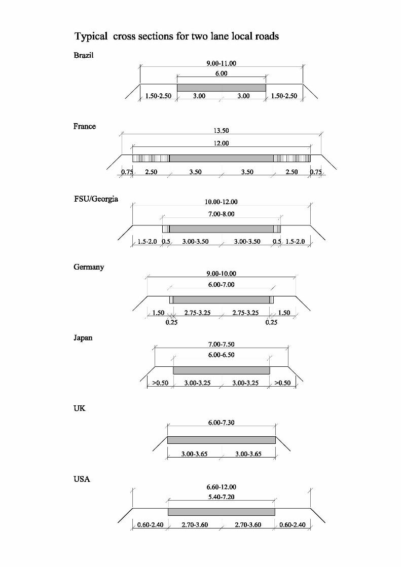
ANNEX 2
Typical Cross-Sections for Two Lane Arterial and Local Roads


![Construction Design Management Policy Design Management Policy.pdfThe Construction (Design and Management) Regulations 2015 [CDM] Introduction The Construction (Design and Management)](https://img.dokumen.tips/doc/110x75/5f21d0ac01944e7e8423b6d6/construction-design-management-policy-design-management-the-construction-design.jpg)