Embed Size (px)
Citation preview
© Faculty of Mechanical Engineering, Belgrade. All rights reserved FME Transactions (2012) 40, 153-164 153
Eugeniusz Rusiński Professor
Wroclaw University of Technology, Poland Faculty of Mechanical Engineering
Jerzy Czmochowski Associate Professor
Wroclaw University of Technology, Poland Faculty of Mechanical Engineering
Damian Pietrusiak Research Assistant
Wroclaw University of Technology, Poland Faculty of Mechanical Engineering
Selected Problems in Designing and Constructing Surface Mining Machinery Contemporary machine design not only needs to meet the applicable requirements, norms and regulations but also requires a novel approach to the designing process. The article presents the essence and role of experimental and numerical analyses, which are becoming increasingly popular in the designing process and in the testing of dynamically loaded structures. What is particularly important in machine modeling is the accuracy of representation and thus the complexity of the model. In order to fully and accurately represent the reality it is necessary to verify and update the models based on experimental tests. Keywords: surface mining, bucket wheel excavator, FEM, experimental techniques
1. INTRODUCTION
Contemporary designs not only have to meet the requirements and standards for surface mining machinery but also should include the results of frequency tests of free and forced vibrations for individual elements and sections.
Owing to the rapidly increasing calculating power of computers it is now possible to solve very complex numerical problems. However, it is also important not to overcomplicate the task if it is possible to obtain sufficiently accurate results using a simpler model. In order to make such a decision one needs expert knowledge of the tested machine. It is important to anticipate the range of potential free vibration frequencies which can influence the use of the machine, and to understand where and how simplifications can be introduced.
The discreet models of steel structures used today are built using either beam elements or shell elements. Using beam elements is not overly complicated and makes it possible to represent the stiffness of the structure. The drawback of this method is that it does not take into consideration the joint stiffness of the superstructure. Most often it is much higher than the stiffness of the beam itself. Neither of these modeling methods includes the influence of the type of joints on the stiffness of the superstructure. In both cases it is crucial that the mass distribution corresponds to the distribution in the stability proof or the one based on machine tests. When analyzing the machine's vibration it is also important to include stress of elements such as elastic and steel lines.
The stress level can influence the stiffness change and thus the frequency of vibrations.
It is possible to update the numerical models so that
they most accurately represent the studied machine. This is initially done already at the stage of mass distribution and introduction of load to the elements of the machine. If there are still large discrepancies with respect to the values obtained during tests, the updating of mass and stress should be verified and repeated. Due to the use of the said simplifications, the updating process may be complicated. It is also possible to change the values of physical parameters such as Young's modulus, stiffness or mass density. Another approach is updating based on purely mathematical methods. Mathematical algorithms directly modify the values of stiffness and mass matrices [1]. Yet such a change in parameters does not provide any physical interpretation. By applying the above methods of updating it is possible to obtain a model which precisely represents the values measured on the machine. However, it is important to realize that a model created in this manner may differ from the real machine with respect to other parameters and in fact does not provide an accurate representation of the real structure.
Models built for the purpose of calculating ultimate and fatigue strength require a more accurate discretization than those built for the purpose of numerical modal analysis. Before a model is created it is important to know what purpose it will serve. Although beam and shell elements are used, which reduces the size of the model, the number of nodes often exceeds 300 000. This may be less problematic in the case of static calculations but hardware and software requirements for eigenvalues solver algorithms are much higher.
However, numerical calculations are based on experimental tests on real machines. It is therefore necessary to verify the assumptions of numerical models. Such verification can justify the chosen calculation method and, most importantly, the boundary conditions for the model. Only after such validation the models may be used by experienced users to only perform numerical analyses in design, to assess the tension level or to perform modal analysis.
Received: June 2012, Accepted: November 2012 Correspondence to: MSc Damian Pietrusiak Wroclaw University of Technology, Lukasiewicza 7/9, 50-371 Wroclaw, Poland E-mail: [email protected]

154 ▪ VOL. 40, No 4, 2012 FME Transactions
2. DESIGNING WITH RESPECT TO THE FATIGUE
When designing superstructures one of the most important elements is the construction joint, which is responsible for the continuous transfer of the flow of tension from one element to another element (or elements). The purpose of each joint is to take components of force through individual elements of the node and to redistribute them evenly on other load-bearing beams. An optimally designed superstructure is one in which all nodes are formed in accordance with ultimate and fatigue strength criteria.
A node, which is part of the superstructure, is composed of several joined elements connected by several various joints of the same or different type [2-6]. The joint in the node is an element of the structure created by connecting flanges of beams via welding, riveting (currently with HUCK bolts) or bolting with fit bolts.
The shape and type of the node are directly related to the kind of elements that will be used to build the superstructure of the machine. Several principles apply to node design, which are related to the strength and durability of the structure.
The first principle requires that all beams (bars) joined in the node, in particular the centers of gravity of their cross sections, should intersect in one point in the node. An eccentric beam joint creates additional bending moments in the node. Another example of unfavorable bending moments occurring in the frame nodes is when the converging beams are on different planes.
The second principle in designing nodes of superstructures requires that frame beams and gusset plates should be positioned on one plane, symmetrically to the plane of the frame. In the case of asymmetrical joint between the beam and the gusset plate there are additional bending stresses caused by the resulting eccentricity.
Beams are connected in the node directly or by means of a gusset plate. Nodes with beams connected directly are used in statically loaded superstructures, such as building structures and machinery in which the variable load does not determine the dimension of the given structure. The nodes of frames without gusset plates have simple structural solutions and are easy to manufacture. The gusset plates themselves do not significantly influence the mass of the structure.
Nodes with gusset plate, shown in Figure 1, are mainly used in superstructures of excavators and stackers.
Figure 1. Connection of load-bearing beam by means of gusset plate
All beams which converge in a given joint are directly connected to the gusset plate. The thickness of gusset plates is chosen depending on the values of forces in beams. A well-designed node delivers load to the gusset plate only in the plane stress state. If the superstructures are dynamically loaded or if the load is variable, then the nodes must be appropriately shaped so as to have the required operational durability. Thus there cannot be any structural notches in the node. Figure 2 shows fatigue cracks on the beam of the bucket wheel boom of an excavator which are the cause of a weld notch [2]. This weld notch could be removed by devising an appropriate post-welding treatment. The gusset plate must be properly shaped and after welding the weld joints should be ground in order to remove the weld notches, as shown in Figure 3.
a)
b)
Figure 2. Fatigue crack on the gusset plate connected to the beam of the bucket wheel boom on an excavator: a) side view, b) top view
Figure 3. Technique of removing weld notches in welded joints
When constructing superstructures of excavators and stackers only joints which are formed according to the
FME Transactions VOL. 40, No 3, 2012 ▪ 155
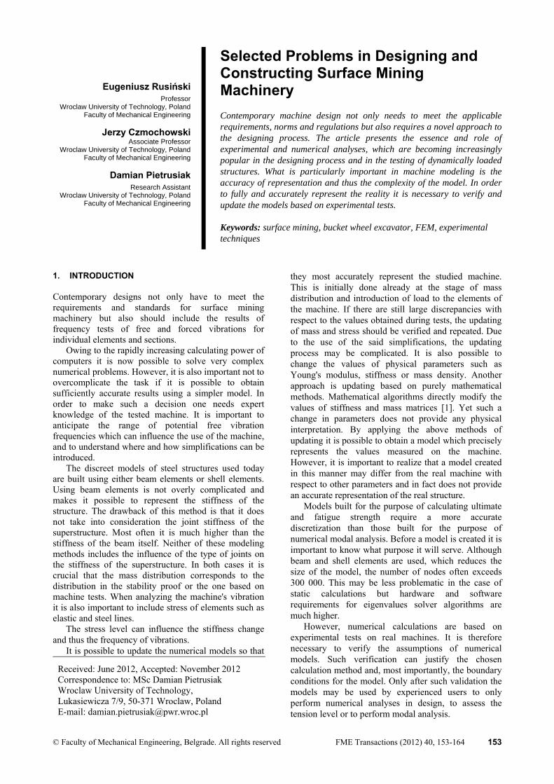
fatigue durability criteria are used because they are subject to variable loads (Figure 4).
a)
b)
c)
Figure 4. Joints used in structures of mining machines
In contemporary superstructures of machinery gusset plates are not used in a traditional way (whenever it is possible) but instead the gusset plate is an integral part of the joint and the beams converging in it. In this case the gusset plate is an extension of webs of appropriately shaped beams, as shown in Figure 4. The structural solution of joints shown in Figure 4 is used in structures which undergo extreme tension and operate under cyclically changing loads.
Additionally, the three solutions for joints, shown in Figure 4 a, b, and c, are characterized by high fatigue strength obtained by connecting beams with gusset plate which is part of the flanges of I-beams. In all cases these nodes create a monolithic structure whose section does not undergo rapid change. The transverse welds are butt welds located away from the points of section change and can easily undergo any mechanical working process (e.g. grinding). The fillet welds which connect flanges with the web of the beams and which are located longitudinally to the direction of the load do not decrease the fatigue strength of the joint.
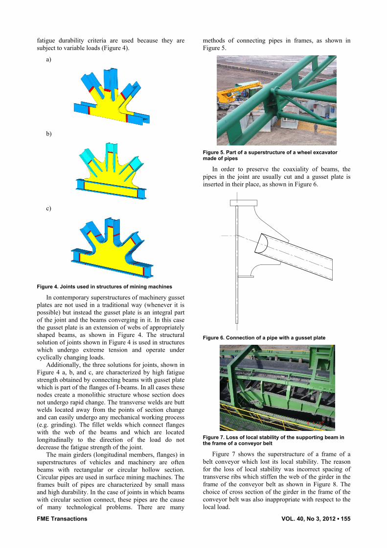
The main girders (longitudinal members, flanges) in superstructures of vehicles and machinery are often beams with rectangular or circular hollow section. Circular pipes are used in surface mining machines. The frames built of pipes are characterized by small mass and high durability. In the case of joints in which beams with circular section connect, these pipes are the cause of many technological problems. There are many
methods of connecting pipes in frames, as shown in Figure 5.
Figure 5. Part of a superstructure of a wheel excavator made of pipes
In order to preserve the coaxiality of beams, the pipes in the joint are usually cut and a gusset plate is inserted in their place, as shown in Figure 6.
Figure 6. Connection of a pipe with a gusset plate
Figure 7. Loss of local stability of the supporting beam in the frame of a conveyor belt
Figure 7 shows the superstructure of a frame of a belt conveyor which lost its local stability. The reason for the loss of local stability was incorrect spacing of transverse ribs which stiffen the web of the girder in the frame of the conveyor belt as shown in Figure 8. The choice of cross section of the girder in the frame of the conveyor belt was also inappropriate with respect to the local load.

156 ▪ VOL. 40, No 4, 2012 FME Transactions
Figure 8. Frame of the conveyor belt with damaged superstructure
The crack shown in Figure 9 is a result of a structural notch which causes a step change in stiffness.
Figure 9. Crack of the gusset plate resulting from a notch caused by a step change in stiffness
3. STRUCTURES DISCREETE MODELS
Superstructures of surface mining machinery are usually modeled using beam and shell elements [8-10]. Mass elements are used to represent the arrangement of mechanical elements and weights, compartments or other elements which do not function as support but as a load to the machine. Numerical models with a complex structural form cannot always be simplified to models entirely made of beam elements. It is often necessary to combine both models. In the case of the model of a feeding bridge of a stacker shown in Figure 10, the main truss is made of beam elements, and the other elements of the superstructure are made of shell elements.
Figure 10. The beam-shell model of the ZGOT 11500 stacker feeding bridge
Surface mining machines are multibody machines [11-12]. The main elements of the body such as booms, masts or jibs are modeled separately. The most important and most difficult is the proper assembly of individual elements so that they represent the real
functioning of machines and properly transfer loads [13]. The greatest difficulty is in the proper connection of all elements by means of lines and pulleys. It is necessary for the forces in all lines to balance out. Over the years various types of hoisting systems have been used, which often requires an individual approach to each machine. (Figures 11 and 12).
Figure 11. Hoisting system of the SRS 1200 excavator
Figure 12. Hoisting system of the SChRs 4600.50 excavator
The next stage is to support the body of the excavator. In many cases a simplified model is used in which the machine undercarriage is substituted by elastic elements of appropriate stiffness. This type of connection is created at the point of support of the upper race of the bearing on balls (Figure. 13). In the case of static calculations of the excavator body this method works well but when conducting numerical modal analysis there is a significant influence of the undercarriage portal on the frequency of free vibrations [14]. A more complex model is needed to perform strength calculations for the bearing areas (Figure 14).
Figure 13. Model of excavator without a portal
FME Transactions VOL. 40, No 3, 2012 ▪ 157
Figure 14. Model of excavator with a portal
In practice the calculations for undercarriage of mining machines are performed separately. However, this approach requires the loads to the body to be properly calculated on the basis of stability proof and operating scenarios.
There is still little knowledge and use in calculations of the influence of the ground stiffness on the structure. This could be relevant in calculations of statics and dynamics of machines.
4. NUMERICAL CALCULATIONS OF ULTIMATE
AND FATIGUE STRENGTH
Calculations of ultimate strength, stability and fatigue strength of brown coal surface mining machines are performed in accordance with the standard [5]. Ultimate strength and stability are tested for loading conditions H, HZ, HZS and HZG with appropriate partial safety coefficients F. The fatigue (operational) strength is performed for loading conditions H with combination coefficient 1b. When assessing fatigue strength the acceptable stress differences are established depending on the type of joint and assessment group.
• Superstructure calculations Because of the substantial dimensions and large span
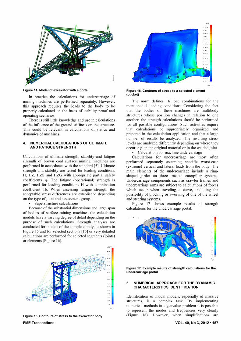
of bodies of surface mining machines the calculation models have a varying degree of detail depending on the purpose of such calculations. Strength analyses are conducted for models of the complete body, as shown in Figure 15 and for selected sections [15] or very detailed calculations are performed for selected segments (joints) or elements (Figure 16).
Figure 15. Contours of stress to the excavator body
Figure 16. Contours of stress to a selected element (bucket)
The norm defines 16 load combinations for the mentioned 4 loading conditions. Considering the fact that the bodies of these machines are multibody structures whose position changes in relation to one another, the strength calculations should be performed for all possible configurations. Such activities require that calculations be appropriately organized and prepared in the calculation application and that a large number of results be analyzed. The resulting stress levels are analyzed differently depending on where they occur, e.g. in the original material or in the welded joint.
• Calculations for machine undercarriage Calculations for undercarriage are most often
performed separately assuming specific worst-case (extreme) vertical and lateral loads from the body. The main elements of the undercarriage include a ring-shaped girder on three tracked caterpillar systems. Undercarriage components such as crawler frames and undercarriage arms are subject to calculations of forces which occur when traveling a curve, including the possibility of blocking or swerving of one of the wheel and steering systems.
Figure 17 shows example results of strength calculations for the undercarriage portal.
Figure 17. Example results of strength calculations for the undercarriage portal
5. NUMERICAL APPROACH FOR THE DYANAMIC
CHARACTERISTICS IDENTIFICATION
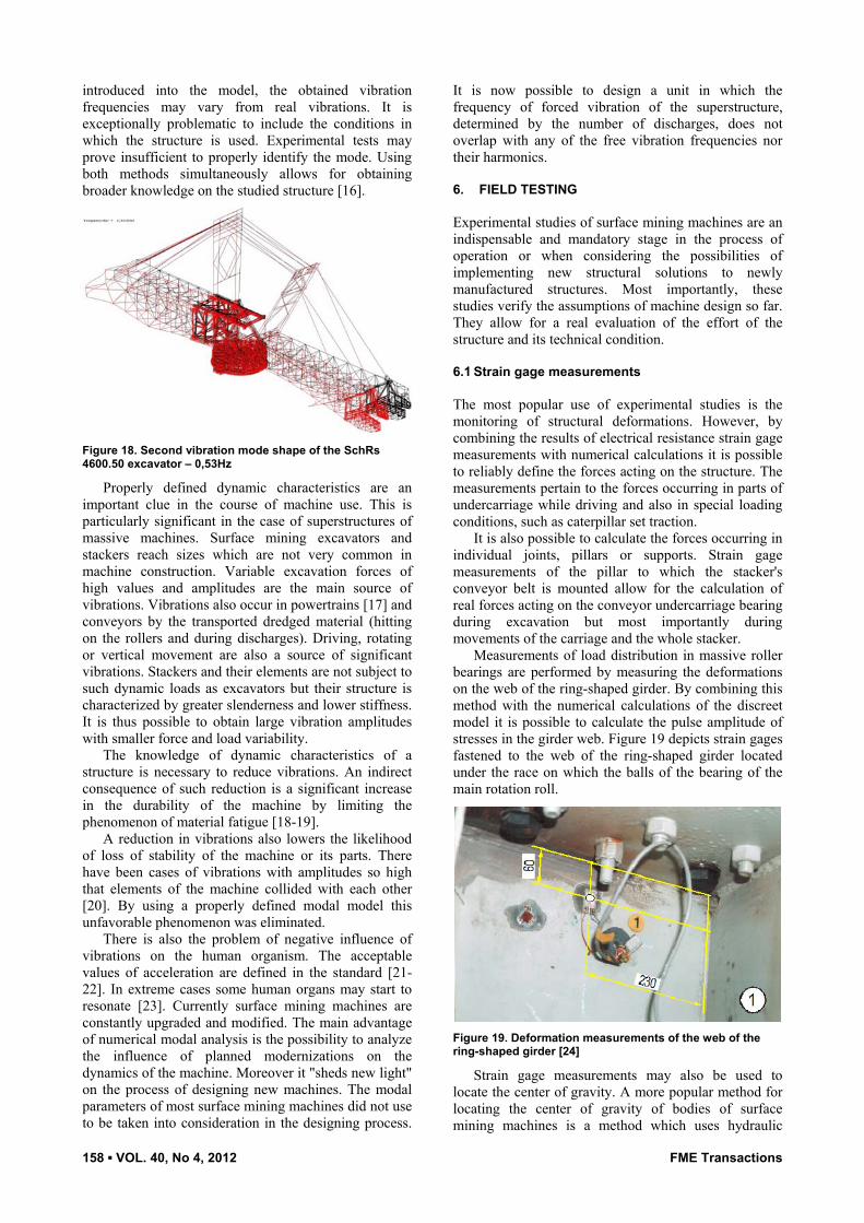
Identification of modal models, especially of massive structures, is a complex task. By implementing numerical methods in eigenvalue problem it is possible to represent the modes and frequencies very clearly (Figure 18). However, when simplifications are
158 ▪ VOL. 40, No 4, 2012 FME Transactions
introduced into the model, the obtained vibration frequencies may vary from real vibrations. It is exceptionally problematic to include the conditions in which the structure is used. Experimental tests may prove insufficient to properly identify the mode. Using both methods simultaneously allows for obtaining broader knowledge on the studied structure [16].
Figure 18. Second vibration mode shape of the SchRs 4600.50 excavator – 0,53Hz
Properly defined dynamic characteristics are an important clue in the course of machine use. This is particularly significant in the case of superstructures of massive machines. Surface mining excavators and stackers reach sizes which are not very common in machine construction. Variable excavation forces of high values and amplitudes are the main source of vibrations. Vibrations also occur in powertrains [17] and conveyors by the transported dredged material (hitting on the rollers and during discharges). Driving, rotating or vertical movement are also a source of significant vibrations. Stackers and their elements are not subject to such dynamic loads as excavators but their structure is characterized by greater slenderness and lower stiffness. It is thus possible to obtain large vibration amplitudes with smaller force and load variability.
The knowledge of dynamic characteristics of a structure is necessary to reduce vibrations. An indirect consequence of such reduction is a significant increase in the durability of the machine by limiting the phenomenon of material fatigue [18-19].
A reduction in vibrations also lowers the likelihood of loss of stability of the machine or its parts. There have been cases of vibrations with amplitudes so high that elements of the machine collided with each other [20]. By using a properly defined modal model this unfavorable phenomenon was eliminated.
There is also the problem of negative influence of vibrations on the human organism. The acceptable values of acceleration are defined in the standard [21-22]. In extreme cases some human organs may start to resonate [23]. Currently surface mining machines are constantly upgraded and modified. The main advantage of numerical modal analysis is the possibility to analyze the influence of planned modernizations on the dynamics of the machine. Moreover it "sheds new light" on the process of designing new machines. The modal parameters of most surface mining machines did not use to be taken into consideration in the designing process.
It is now possible to design a unit in which the frequency of forced vibration of the superstructure, determined by the number of discharges, does not overlap with any of the free vibration frequencies nor their harmonics.
6. FIELD TESTING
Experimental studies of surface mining machines are an indispensable and mandatory stage in the process of operation or when considering the possibilities of implementing new structural solutions to newly manufactured structures. Most importantly, these studies verify the assumptions of machine design so far. They allow for a real evaluation of the effort of the structure and its technical condition.
6.1 Strain gage measurements
The most popular use of experimental studies is the monitoring of structural deformations. However, by combining the results of electrical resistance strain gage measurements with numerical calculations it is possible to reliably define the forces acting on the structure. The measurements pertain to the forces occurring in parts of undercarriage while driving and also in special loading conditions, such as caterpillar set traction.
It is also possible to calculate the forces occurring in individual joints, pillars or supports. Strain gage measurements of the pillar to which the stacker's conveyor belt is mounted allow for the calculation of real forces acting on the conveyor undercarriage bearing during excavation but most importantly during movements of the carriage and the whole stacker.
Measurements of load distribution in massive roller bearings are performed by measuring the deformations on the web of the ring-shaped girder. By combining this method with the numerical calculations of the discreet model it is possible to calculate the pulse amplitude of stresses in the girder web. Figure 19 depicts strain gages fastened to the web of the ring-shaped girder located under the race on which the balls of the bearing of the main rotation roll.
Figure 19. Deformation measurements of the web of the ring-shaped girder [24]
Strain gage measurements may also be used to locate the center of gravity. A more popular method for locating the center of gravity of bodies of surface mining machines is a method which uses hydraulic

FME Transactions VOL. 40, No 3, 2012 ▪ 159
actuators. They are used to lift the body and by reading the values of pressure in each actuator it is possible to calculate the center of the mass. Strain gage measurements enable calculation of the center of mass of the whole machine with the undercarriage. A disadvantage of this method is that it is limited to machines traveling on rails, most of which are rather small. The measurement is made by reading the values on the strain bridges bonded to the rails while the machine is traveling there and back (Figure 20).
Figure 20. Measuring the deformation of rail under a load-stacker [25]
This enables the estimation of distribution of forces in supports, which in turn enables the calculation of center of mass.
It is also often necessary to calculate the real load acting on the excavator in result of the excavation process. This is done by measuring the deformation on the momentum beam of the excavator. As a result we can calculate the courses of digging forces depending on the type of the currently excavated coal overburden or the coal bed. It is also possible to calculate the real values of forces acting on the machine during overloads. Sometime strain gage is measured only on the bucket wheel shaft [26] (Figure 21).
Figure 21. Measurement of excavation forces
6.2 Measurement of vibrations. Experimental and
operational modal analysis.
Modal analysis on a real vehicle is crucial due to the information it provides which can be used to verify the
numerical model. A two-fold approach, experimental and numerical, produces the best results and enables an accurate simulation of the structure's operation.
However, performing this test on such a massive structure is an extremely complicated endeavor. Today the most popular and commonly used method is experimental modal analysis[20,27-29]. By knowing the relationships between energy of excitement and energy of response it is possible to calculate the transfer function which defines the dynamic characteristics. Such test includes the influence of all environmental factors, structural or assembly changes. This method is quite problematic due to the need to excite the machine. It is very difficult to borderline impossible to provide a measurable forced vibration of a magnitude that could excite a structure with a nearly 900 Mg body. So far it has been done by attaching a large mass to the bucket wheel boom (Figures 21 and 22) and quickly releasing it by means of a special device (Figure 21).
Figure 21 Device used to quickly release the mass after reaching the given force
Figure 22. Attaching a bulldozer to the bucket wheel boom
At present the operational modal analysis is becoming widely used [30-31]. It does not require artificial excitement of the structure. In order to determine the transfer function it is sufficient to know the system response. Therefore the vibrations may be recorded during normal operation of the machine. An additional advantage is the fact that the dynamic characteristics measured in this manner take into account the potential influence of digging forces, mass forces (from the excavated material) or the contact of the boom with the surface. This could be crucial

160 ▪ VOL. 40, No 4, 2012 FME Transactions
because dynamic characteristics established without consideration of forces occurring during excavating or stacking may vary from what really happens during operation.
A key aspect of performing accurate measurements is the positioning of accelerometers. The best method is to use a minimum number of sensors to obtain the most information at the same time making sure that spatial aliasing does not occur. It is also very important not to position sensors in the vibration nodes. This is possible by performing numerical analysis beforehand. By anticipating which modes may occur it is possible to fulfill both of the abovementioned requirements. Figure 23 illustrates the positioning of the points and directions of acceleration measurement on the 4600.30 excavator.
Figure 23. SChRs 4600.30 excavator with designated points of accelerometric measurements
This approach clearly shows how the experimental and numerical methods complement each other and how important it is to use both methods simultaneously.
The analysis itself requires excellent preparation and organization. The largest machines are more than 120 meters long and 60 meters tall. Hence, hundreds of meters of wire must be placed on the machine under study in order to connect the sensors with the recorder. The placing and protection of the wires must be carefully planned. Due to many rotating and moving parts and other unfavorable factors it is very easy to break a wire or even damage the equipment.
Based on the experimental analysis conducted in such manner it is possible to determine the dynamic characteristics. Specific frequencies and mode shapes are identified, both global (Figure 24) and local.
Figure 24. First vibration mode shape of the SChRs 4600.30 excavator body – 0.38Hz
The vibration levels of individual components and whole machines are also measured. These allow for the approximate calculation of dynamic loads to the structure and, most importantly, verify if the results are in accordance with the values established in the standard. This is used in the assessment of the technical condition or in the "search" for resonance, and enables the inclusion of dynamic loads in the designing process.
6.3 Nondestructive test
Of popular use in the testing of surface mining machines are various nondestructive methods, i.e. ultrasound, magnetic particle, penetrant testing, etc. Of these the magnetic particle testing is the most popular. With the complexity of structures and difficulty in accessing many areas these tests win over other methods due to their ease of testing. Another aspect worth mentioning is the relatively low cost. By using this method it is possible to locate new cracks or monitor the spread of existing ones (Figure 25)
Figure 25. Nondestructive test of an excavator joint
This is of high importance for the safe use of the machine and the safety of the crew operating it.
7. ASSESMENT OF THE TECHNICAL CONDITION
AFTER MANY YEARS OF OPERATION
In order to establish the degree of degradation of excavators and stackers (surface mining machines) and their technical condition, a comprehensive testing methodology has been devised (Figure 26). An important aspect of this methodology is the tracking of the history of operation, i.e. the operational history of the machine. These machines are used in various geological conditions and thus are subject to various loads. In the course of operation overhauls are scheduled, whose purpose is to renew the unit, section or component before it reaches a limit state caused by wear and aging. In spite of this, between overhauls, ultimate or fatigue cracks occur which may result from rapid overloads. An analysis of the history of such events serves as the basis for structural changes or upgrades of whole sections [32,35].

FME Transactions VOL. 40, No 3, 2012 ▪ 161
In addition to the material effort of the superstructure FEM calculations [3] are performed for loads and loading conditions defined by current norms [5,6]. Therefore, one of the most important stages in the assessment of technical condition are the FEM strength calculations, which enable the verification of the assumed cross sections and location of points of largest material effort. These points are then the subject of tests on a physical object, e.g. nondestructive defectoscopic tests, plate thickness measurements, deformation measurements.
What is also significant in numerical simulations is the measurement of vibrations, i.e. their frequency, amplitude, displacements, deformations and accelerations [20]. If the values resulting from these tests exceed the values defined in norms they should be included in the load models.
Therefore in order to assess the state of degradation of a machine and estimate the period of its potential serviceability it is necessary to perform comprehensive experimental and numerical tests which are outlined in the flow chart (Figure 28).
Currently new machines have monitoring systems are installed in them which record the deformation (stress) changes in selected points of the superstructure, the so-called reference points. An example of such systems is the stress measurement system used in the KWK-910 excavator in PGE GiEK SA Turów Brown Coal Mine branch, which has been monitoring the excavator since the beginning of operation [2]. Based on the stress changes the cycles increments are calculated and cycles of specific value, e.g. using the Rainflow method. This results in a spectrum of stress change ranges shown in Figure 26.
log
n i
i [MPa]
0
1
2 4 7 9 11 13 15 17 20 22 24 26 28 31 33 35 37 39 42 44 46 48 50 52 55 57 59 61 63
2
3
4
5
6
7
8
9
Figure 26. Spectrum of stress change ranges in the reference point of the KWK-910 excavator after 3430h of operation [2]
If the measured data does not span the whole period of machine operation, a long-term measurement of operational stress is performed and the results are extrapolated onto the past and future periods of operation.
This approach is commonly used in all areas of operation of welded structures subject to variable loads: surface mining machines [2,33-35], construction machines [35], hoisting equipment, bridges [36].
Assessment of fatigue strength is conducted based on the S-N curves (Figure 27) which are recommended in guidelines [37] as best suited for the spectrum of variable amplitude stress. The presented fatigue curves use two exponents m and 2m-1 in specific ranges.
NC
N
ND
m
2m-1
D
C
104 105 106
2 106·
107 108
Figure 27. S-N curve for spectrums of variable amplitude stress
The degree of fatigue damage Dr caused by Nr cycles recorded in Tr time of the spectrum in accordance with Miner's hypothesis of linear summation of damages is calculated from the formula:
q
i i
ir N
nD
1 (1)
where:
Dim
D
i
Di dla
NN
12
(2)
Dim
D
i
Di dla
NN
(3)
Thus the level of fatigue damage as a result of Nr cycles is equal to:
12
11
1mq
pi D
ii
mp
i D
ii
Dr nn
ND
(4)
The durability condition is defined as follows:
dr DD (5)
where: Dd = 1,0 according to Eurocode 3, Dd = 0,2 ÷ 0,5 according to Hobbacher (2007) depending on the degree of consequence of damage to a given element.

162 ▪ VOL. 40, No 4, 2012 FME Transactions
Figure 28. Methodology of assessing the technical condition of superstructures of machines
8. CONCLUSIONS
Surface mining machines, i.e. excavators or stackers are designed for 40 to 50 years of operation. In many cases these machines are built for mines for the period of excavation of coal or other deposits. Of special importance are superstructures of excavators or stackers. The steel structure designs in these machines must meet the criteria of ultimate and fatigue strength throughout the operation period and simultaneously meet the standards requirements [5-6]. There have been cases where the structure was designed in accordance with requirements in norms and during operation of excavators and stackers fatigue cracks started to appear in their steel structures (Figures 2.3 and 2.10). In the majority of cases the reasons for this are known and include the following: material faults (currently very rarely), improper technology during manufacture, badly designed joints which do not meet the fatigue strength criterion, frequencies of free vibrations of machine superstructures, cases of random overloads (landslide, fires, etc.)
The basic requirement which should be met in a design of a steel superstructure for an excavator, stacker or other machine is to optimally design the joints of the superstructure in these machines with respect to the fatigue strength criterion. The optimal geometric shape may be obtained if the load spectrum is known and if professional discreet models of superstructures are built using shell elements for discretization of elements with (sub-parametric) high-order shape functions. Additionally it is important to devise the technology of building nodes of this class (Figure 3) with complete control of the created welds.
Most damages to steel superstructures and fatigue cracks are causes by vibrations and resonance of these structures. The applicable standards do not require testing of superstructure of machines against resonance. Therefore in many cases booms of multibucket
excavators, for instance, resonate to some degree during operation. The proper approach is to perform a modal analysis for the undercarriage and body of a machine in the design stage. To do this, discreet models are needed of complete machine structures for which a numerical modal analysis is performed using the FEM method. After constructing the machine, the FEM discreet models of superstructures of machines are tuned by means of experimental studies.
Every newly constructed and approved machine and its components such as body, booms, pylons, undercarriage should undergo experimental testing with respect to free vibration frequencies (an operational modal analysis should be carried out).
ACKNOWLEDGMENT
Research co-financed by the European Union within the European Social Fund.
REFERENCES
[1] Miller B.: Dostrajanie modelu matematycznego konstrukcji do modelu fizycznego, Rozprawa doktorska, Rzeszów, 2001.
[2] Kowalczyk M.: Wymiarowanie spawanych konstrukcji nośnych maszyn podstawowych górnictwa odkrywkowego w zakresie trwałości zmęczeniowej, Praca doktorska, Raport serii PRE 1/2010, IKiEM, Politechnika Wrocławska, Wrocław, 2010.
[3] Rusiński, E., Czmochowski J. and Pietrusiak D.: Problems of steel construction modal models indentification, Eksploatacja i Niezawodność – Maintenance and Reliability Vol. 14, No. 1, pp. 54-61, 2012;
[4] Rusiński, E.: Computer-aided design of basic machines for open-cast mining, in: Proceedings of Manufacturing and management in 21st century.

FME Transactions VOL. 40, No 3, 2012 ▪ 163
Scientific conference, 16-17.9. 2004, Ohrid, Republic of Macedonia, Chapter 2, pp. 65-70.
[5] Standard - DIN 22261-2 Bagger, Absetzer und Zusatzgeräte in Braunkohlentagebauen.
[6] Standard - EN 1993-1-1:2005 Eurocode 3: Design of Steel Structure-Part 1.9-Fatigue, 2005.
[7] Arsić, M., Bošnjak, S., Zrnić, N., Sedmak, A. and Gnjatović, N.: Bucket wheel failure caused by residual stresses in welded joints, Engineering Failure Analysis, Vol. 18, No. 2, pp. 700–712, 2011.
[8] Rusiński, E., Czmochowski, J. and Smolnicki, T.: Advanced Finite Element Method for Load-carrying Structures of Machines, Oficyna Wydawnicza PWr., Wroclaw, 2000.
[9] Smolnicki, T. and Rusiński E.: Superelement - Based modeling of load distribution in large size slewing bearings, Journal of Mechanical Design,, Vol. 129, No. 4, pp. 459-463,2007.
[10] Zienkiewicz, O.C., and Taylor, R.L.: The finite element method. Vol. 1, Vol. 2., McGraw-Hill Bool Company, London, 1991.
[11] Bošnjak, S., Zrnić, N. and Gnjatović, N.: Geometry of the substructure as a cause of bucket wheel excavator failure, Machine Design, edited by S. Kuzmanović, pp. 135-140, University of Novi Sad, 2009.
[12] Bošnjak, S., Petković, Z., Matejić, P., Zrnić, N., Petrić, S. and Simonović, A: Analysis of Stress-Strain State of Bucket Wheel Excavator Revolving Platform Structure – Fundament of Efficient Reconstruction, Structural Integrity and Life, Journal of the Society for Structural Integrity and Life, Vol. 5, No. 3, pp. 129-142, 2005.
[13] Rusiński, E., Moczko, P. and Czmochowski, J.: Numerical and experimental analysis of mines loader boom crack, Automation in Construction, Vol. 17, No. 3, pp. 271-277, 2008.
[14] Smolnicki, T., Rusiński, E. and Przybyłek, G.: Wybrane Aspekty Dostrajania Modeli Dyskretnych Koparki Wielonaczyniowej Kołowej. Górnictwo Odkrywkowe, pp. 7-8, 2006.
[15] Karliński, J., Rusiński, E. and Smolinicki, T.: Protective structures for construction and mining machines operators, Automation in Construction, Vol. 17, No. 3, pp. 232-244, 2008.
[16] Bošnjak, S., Zrnic, N. and Oguamanam, D.: On the dynamic modeling of bucket wheel excavators, FME Transactions, Vol. 34, No. 4, pp. 221-226, 2006.
[17] Wilk, A., Madej, H. and Figlus, T.: Analiza możliwości obniżenia wibroaktywności korpusu przekładni zębatej, Eksploatacja i niezadowność – Maintenance and reliability; Vol. 2, pp. 42-49, 2011.
[18] Bošnjak, S., Zrnić, N., Simonović, A. and Momčilović, D.: Failure analysis of the end eye connection of the bucket wheel excavator portal tie-
rod support, Engineering Failure Analysis, Vol. 16, No. 3, pp. 740-750, 2009.
[19] Rusiński, E., Czmochowski, J., Iluk A. and Kowalczyk M.: An analysis of the causes of a BWE counterweight boom support fracture., Engineering Failure Analysis, Vol. 17, No 1, pp. 179-191, 2010.
[20] Czmochowski, J.: Identyfikacja modeli modalnych maszyn urabiających w górnictwie węgla brunatnego, Oficyna Wydawnicza Politechniki Wrocławskiej, Wrocław, 2008.
[21] Standard - Eurokod 7. Projektowanie geotechniczne. Część 1. Zasady ogólne. PN-EN 1997-1, 2008.
[22] Standard - PN-N-01357:1990, Metody pomiarów i oceny drgań maszyn pod względem bezpieczeństwa i higieny pracy.
[23] Cempel, C.: Wibroakustyka stosowana, Warszawa: PWN, 1989, (in Polish).
[24] Smolnicki, T.: Physical Aspects of the Coherence Between the Large-Size Rolling Bearings and Deformable Support Structures, Wrocław University of Technology Publishing House, Wrocław, 2002.
[25] Smolnicki T, Stańco M. Determination of center of gravity of machines with the rail undercarriage, Solid State Phenomena 2010, 165, 359-364
[26] Bošnjak, S., Zrnić, N. and Petković, Z.: Bucket wheel excavators and trenchers – Computer added calculation of loads caused by resistance to excavation, Machine Design, monograph edited by S. Kuzmanović, University of Novi Sad, pp. 121-128, 2008.
[27] Gottvald, J.: Measuring and Comparison of Natural Frequencies of Bucket Wheel Excavators SchRs 1320 and K 2000, GEMESED’11, in: Proceedings of the 4th WSEAS International Conference on Energy and Development - Environment – Biomedicine, 2011, Corfu Island, Greece, pp. 335-340.
[28] Gottvald J.: The calculation and measurement of the natural frequencies of the bucket wheel excavator schrs 1320 / 4x30, Transport, Vol. 25, No. 3, pp. 269-277, 2010.
[29] Rusiński, E. and Czmochowski, J.: Die Modalanalyse des Oberbaus eines Baggers vom Typ SchRs-800, Surface Minning, Braunkohle other Miner., Vol. 53, No 3, 2001.
[30] Pietrusiak, D., Czmochowski, J., Kowalczyk, M. and Łągwa Ł.: Określenie właściwości dynamicznych koparki KWK1500 metodą eksploatacyjnej analizy modalnej., Górnictwo Odkrywkowe 4/2010.
[31] Rusiński, E., Dragan, S., Moczko, P. and Pietrusiak D.: Implementation of experimental method of determining modal characteristics of surface mining machinery in the modernization of the excavating unit, Archives of Civil and Mechanical Engineering Vol.12, No.4, pp. 471-476, 2012.

164 ▪ VOL. 40, No 4, 2012 FME Transactions
[32] Kowalewski, J.: Assessment of Remaining Fatigue Life for Surface Mining Equipment, Surface Mining, Vol. 53, No. 4, 2001.
[33] Kowalczyk, M., Czmochowski J. and Rusiński E.: Construction of diagnostic model of the states of developing fault for working part of the multi-bucket excavator, Maintenance and reliability, Vol. 42, No. 2, pp. 17-24, 2009.
[34] Rusiński, E., Moczko P. and Kanczewski K.: Numeryczno-doświadczalne prognozowanie trwałości elementów ustrojów nośnych maszyn, Transport Przemysłowy, 4, pp. 25-29, 2003.
[35] Malinowski, J. and Myśliwiec J.: Evaluation of Fatigue Life and Strength of Chosen Sub-Assemblies of Bucket Loader, 1st Conference Off-Road Machines and Vehicles in Theory and Practice, Wrocław, pp. 273- 279, 1996.
[36] Czudek, H. and Pietraszek T.: Trwałość stalowych konstrukcji mostowych przy obciążeniach zmiennych, WKiŁ, Warszawa, 1980.
[37] Hobbacher A.: Recomendations for Fatigue Design of Welded Joints and Components, IIW Document XIII-2151-07/XV-1254-07, Paris, 2007.
ОДАБРАНИ ПРОБЛЕМИ У ПРОЈЕКТОВАЊУ РУДАРСКИХ МАШИНА НА ПОВРШИНСКИМ
КОПОВИМА
Еугениуш Рушински, Јиржи Шмоховски, Дамиан Пиетрушиак
Дизајн савремених машина не треба само да задовољи захтеве, норме и прописе већ захтева и нов приступ процесу пројектовања. У овом раду представљена је суштина и улога експерименталних и нумеричких анализа, које постају све популарније у процесу пројектовања и тестирања динамички оптерећених конструкција. Оно што је нарочито важно у процесу моделирања јесте тачност а самим тим и сложеност модела. Да би се у потпуности и прецизно представилo реално стање потребно је унапређивање модела на основу експеримената.