Embed Size (px)
Citation preview

SEL-RPM Data Sheet
Redundant Power Module
Features and BenefitsThe SEL Redundant Power Module (RPM) combines up to three ac sources and one dc source to provide a single, reliable dc output to power protection, monitoring, and control equipment. Large energy storage capacitors provide ride through and support switch or breaker trip/close applications when all input sources are lost.
Dependable control power and ride through from the SEL-RPM provide the following advantages:
➤ Keeps protection, automation, and SCADA running during battery servicing or power interruptions.
➤ Reduces device restarts.
➤ Increases device availability.
➤ Increases the reliability of control power, especially in stations without batteries.
➤ Provides many advantages of a dual battery system at a fraction of the cost.
➤ Provides energy for 30 A, 200 ms tripping, in accordance with IEEE C37.90 and EN 60255-1.
➤ 1/8 farad (F) capacitor stores 1300 watt-seconds nominal of energy to trip breakers.
➤ Powers a 6-watt SEL-351 Protection System for 3.5 minutes, a 25-watt load for 50 seconds, and a 100-watt load for 12 seconds, typical.
➤ Includes a capacitor output (unregulated) for reliable energy and high surge currents.
Schweitzer Engineering Laboratories, Inc. SEL-RPM Data Sheet

2
OverviewThe SEL-RPM provides reliable dc power as well as ride through to improve the availability of critical systems.
125 Vdc ModelDC Input: One (1) 125 Vdc
AC Input: Three (3) 120 Vac
DC Output: One (1) unregulated 125 Vdc, 100 W
Front-Panel IndicatorsLEDs indicate the status of the four inputs and one output.
Rear-Panel Control and IndicatorA rear-panel jumper connects the capacitor bank to the output (OPERATE) or disconnects the capacitor bank and discharges it (DISCHARGE). An LED adjacent to the jumper indicates when the capacitor bank voltage exceeds 30 Vdc.
Principles of OperationThe dc applied to the dc input terminals passes through a full-wave bridge rectifier to provide a polarity-insensitive input and to prevent the internal dc bus from backfeeding the dc input.
With a dc input only, the 126 mF/250 Vdc capacitor bank charges from the internal dc bus through a current-limit-ing resistor and a blocking diode. The capacitor bank will fully charge from zero in about 3.4 seconds. The SEL-RPM output is protected from backfeed by a block-ing diode.
For a dc-only input, the no-load output voltage is the input voltage minus the diode voltage drops (about 2 Vdc). Thus, an input voltage of 125 Vdc produces an output voltage of approximately 123 Vdc.
The three ac inputs are transformer-isolated and full-wave bridge rectified. The rectifier outputs drive the same internal dc bus as the dc input rectifier.
Under no load, the capacitor bank charges to nearly the peak of the ac inputs, multiplied by the isolation trans-former turns ratio (120/130), minus the diode drops
(about 2 Vdc). With 120 Vac applied to one or more ac inputs, the no-load output voltage reaches approximately 120 • √2 • (120/130) – 2 = 154 Vdc.
A filter reactor smooths the rectified ac and an inrush limiting resistance reduces input current surges upon energization from any source.
Figure 11 shows a plot of the output voltage versus load for various input source configurations.
Fuses on all four inputs protect the SEL-RPM from most internal and external faults. A fuse on the output of the SEL-RPM, in conjunction with a diode across the output, protects the SEL-RPM from accidental reverse polarity voltage being applied to the capacitor bank of the SEL-RPM. The fuses are sized to conservatively handle the surges from energizing the SEL-RPM and from ener-gizing devices connected to the output of the SEL-RPM. The fuses also withstand repeated trip and close opera-tions of circuit breakers.
The SEL-RPM is designed to withstand crowbar short-circuits on the output. One or more fuses will blow under this condition.
Figure 1 SEL-RPM Typical Application
+
–
1/8 FCommunications
Controller
100 WContinuous
DC OUTPUT125 Vdc DC
AC3
Protective Relay
AC1
AC2120 Vac60 Hz
Protective Relay
+
OPERATEDISCHARGE
SEL-RPM Data Sheet Schweitzer Engineering Laboratories, Inc.

3
Features Reliable Control PowerDC control power can be a single point of failure. Con-trol power can be interrupted or lost completely because of dc faults, battery charger failures, testing, and mainte-nance incidents.
When using a single source of control power, any inter-ruption, even as short as 100 ms can cause equipment to restart. Restarts cause a loss of availability. When using the SEL-RPM, in the event of a disturbance of one source, the other sources continue to provide uninter-rupted control power. The SEL-RPM provides many of the advantages of a dual dc system at a fraction of the cost. Common sources to combine include the following:
➤ DC Battery
➤ Station Service
➤ Alternate Station Service
➤ Backup Generator
➤ Instrument Transformers
Normal OperationDuring normal operation, one or more sources are con-nected to a dc output bus via heavy-duty diodes, as shown in Figure 1. AC sources are isolated through transformers. Output combining ensures that the highest voltage source powers the output and maximizes energy storage and ride through. Transition to the next highest voltage source occurs without interruption when any source is lost.
Ride Through DisturbancesThe SEL-RPM energy storage capacitors provide ride through during the loss of all input sources. Ride-through time depends on the load and device dropout voltage.
Some ride-through applications include:
➤ Transfer switch operation, backup generator starting, or automatic reclosing.
➤ Capacitor-trip the breaker when all sources are lost.
➤ Trip-on-loss of control power and other safety schemes.
➤ Power relays long enough to trip breaker and store event record after the loss of control power.
Simple to UseSimply ensure the devices you intend to connect to the SEL-RPM are properly rated to handle the unregulated capacitor voltage output. See Table 2 for typical power supply ratings of SEL devices. The SEL-RPM has no set-tings, and it requires no maintenance because there are no batteries, firmware, or any other components that wear out or need attention.
Parallel OperationTo increase the number of input sources or the ride-through capacity, you can connect SEL-RPM devices in parallel (see Figure 9). Isolation diodes block one SEL-RPM from backfeeding the other.
Safety➤ Capacitors can be discharged manually to a safe
level in less than 10 seconds by using the rear-panel jumper installed in the DISCHARGE position. An LED adjacent to the jumper illuminates when capacitor bank voltage exceeds 30 V.
➤ Input voltage sources are fuse-protected from indefinite output short circuits.
Five Fuses on Rear PanelEach ac input is protected by a 6 A slow-blow fuse (Bel Fuse 0654R6000-51). Both the dc input and output are protected by a 10 A fuse (Schurter 8020.5021 or equiva-lent). Spare fuses for each input and the output are pro-vided on the rear panel.
Rugged and Reliable DesignThe SEL-RPM is designed with oversized diodes rated for 80 A and bridge rectifiers rated for 35 A for reliable performance even after repeated short-circuit conditions.
Front- and Rear-Panel IndicatorsLEDs show the status of each input, the output, and the capacitor charge, as described in Table 1.
Schweitzer Engineering Laboratories, Inc. SEL-RPM Data Sheet
4
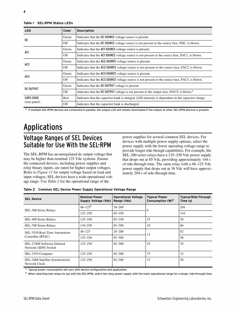
ApplicationsVoltage Ranges of SEL Devices Suitable for Use With the SEL-RPMThe SEL-RPM has an unregulated dc output voltage that may be higher than nominal 125 Vdc systems. Ensure the connected devices, including power supplies and relay binary inputs, are rated for higher output voltages. Refer to Figure 11 for output voltage based on load and input voltages. SEL devices have a wide operational volt-age range. Use Table 2 for the operational range of the
power supplies for several common SEL devices. For devices with multiple power supply options, select the power supply with the lower operating voltage range to provide longer ride-though capabilities. For example, the SEL-300 series relays have a 125–250 Vdc power supply that drops out at 85 Vdc, providing approximately 144 s of ride-through time. The same relay with a 48–125 Vdc power supply that drops out at 38 Vdc will have approxi-mately 204 s of ride-through time.
Table 1 SEL-RPM Status LEDs
LED Color Description
DCGreen Indicates that the DC SOURCE voltage source is present.
Off Indicates that the DC SOURCE voltage source is not present or the source fuse, FDC, is blown.
AC1Green Indicates that the AC1 SOURCE voltage source is present.
Off Indicates that the AC1 SOURCE voltage source is not present or the source fuse, FAC1, is blown.
AC2Green Indicates that the AC2 SOURCE voltage source is present.
Off Indicates that the AC2 SOURCE voltage source is not present or the source fuse, FAC2, is blown.
AC3Green Indicates that the AC3 SOURCE voltage source is present.
Off Indicates that the AC3 SOURCE voltage source is not present or the source fuse, FAC3, is blown.
DC OUTPUTGreen Indicates that the DC OUTPUT voltage is present.
Off Indicates that the DC OUTPUT voltage is not present or the output fuse, FOUT, is blown.a
a If multiple SEL-RPM devices are connected in parallel, the output LED will remain illuminated if the output of other SEL-RPM devices is present.
CAPS CHGD (rear panel)
Red Indicates that the capacitor bank is charged. LED intensity is dependent on the capacitor charge.
Off Indicates that the capacitor bank is discharged.
Table 2 Common SEL Device Power Supply Operational Voltage Range
SEL DeviceNominal Power Supply Voltage (Vdc)
Operational Voltage Range (Vdc)
Typical Power Consumption (W)a
a Typical power consumption will vary with device configuration and application.
Typical Ride-Through Time (s)
SEL-300 Series Relays48–125b
b When selecting new relays to use with the SEL-RPM, select the relay power supply with the lower operational range for a longer ride-through time.
38–2006
204
125–250 85–350 144
SEL-400 Series Relays 125–250 85–350 15 58
SEL-700 Series Relays 110–250 85–300 10 86
SEL-3530 Real-Time Automation Controller (RTAC)
48–125 38–20015
82
125–250 85–300 58
SEL-2740S Software-Defined Network (SDN) Switch
125–250 85–300 25 35
SEL-3355 Computer 125–250 85–300 75 12
SEL-2488 Satellite-Synchronized Network Clock
125–250 85–300 15 58
SEL-RPM Data Sheet Schweitzer Engineering Laboratories, Inc.

5
Source Diversity Connect the SEL-RPM to all three phases of control power or to a potential transformer (see Figure 2). Only a three-phase fault would remove all ac sources. At least one phase will be healthy for all other faults.
Powering Protection and Control DevicesIn Figure 3, the SEL-RPM provides control power to four relays. See Figure 10 for typical run times.
Install in Every PanelInstall one SEL-RPM per panel to power multiple relays, as shown in Figure 4. You can add a second SEL-RPM device in parallel to provide a longer ride-through time. Alternatively, supply System A protection from one SEL-RPM and System B protection from another SEL-RPM for added redundancy.
Trip Breakers An SEL-RPM can trip breakers, even when all sources have been lost. The SEL-RPM stores 1300 watt-seconds nominal of energy. Most trip coils require less than 60 watt-seconds to operate, allowing the SEL-RPM to supply breaker trip coils and power the relay for many seconds after the total loss of all inputs.
Figure 2 SEL-RPM Connected to Diverse Sources
Figure 3 SEL-RPM Providing Control Power to Multiple Relays
AC From Control Power, PT, or Generator
To Loads
+ –SEL-RPM
DC OUTPUT
AC1 SOURCE
AC2SOURCE
AC3 SOURCE
H N H N H N
1 2 3 4 5 6
11 12
DC IN
DC System
7 8
+ –
IED
IED
IED
IED
AC Sources
+ –SEL-RPM
DC OUTPUT
AC1 SOURCE
AC2SOURCE
AC3 SOURCE
H N H N H N
1 2 3 4 5 6
11 12
DC IN
DC System
7 8
+ –
Figure 4 SEL-RPM Installed in a Panel
SEL-RPM
Schweitzer Engineering Laboratories, Inc. SEL-RPM Data Sheet

6
Trip-on-Loss of Control Power Safety SchemeKeep people and equipment safe and protected by designing a safety scheme that trips breakers after the loss of all control power sources. You can use the relay
dc monitor, as shown in Figure 5, and trip at a low volt-age threshold where the SEL-RPM still has energy, as shown in Figure 6.
Monitoring an SEL-RPM With an SEL Relay or Automation ControllerYou can use various SEL relays and automation control-lers to monitor the status of an SEL-RPM. Use binary inputs to determine if an input voltage source is present, and use a dc monitor to monitor the SEL-RPM output voltage, if required. Refer to Figure 7 for typical connec-tions from the SEL-RPM to an SEL relay. When con-necting the ac voltage sources to the relay or automation controller, ensure the binary input debounce or voltage type is set to ac. Refer to Table 3 for summarized appli-cation notes for various SEL devices.
NOTE: Refer to the relay instruction manual for settings details when connecting ac to binary inputs.
Figure 5 SEL-RPM Providing Control Power to the Relay and the Trip Circuit
+ –
Relay TRIPPS
TripCoil
AC Sources
SEL-RPM
DC OUTPUT
AC1 SOURCE
AC2SOURCE
AC3 SOURCE
H N H N H N
1 2 3 4 5 6
11 12
DC IN
DC System
7 8
DC Monitor
+ –
Figure 6 Relay Logic for Low DC Voltage Tripping
PU
DO Trip Breaker
CoordinationTimer
(Vdc < 105)
Figure 7 Installation Example for Monitoring the SEL-RPM Input Status and Output Voltage
Table 3 Options for Monitoring the SEL-RPM (Sheet 1 of 2)
Product LineSEL-RPM DC Input Monitoring
SEL-RPM AC Input Monitoring
SEL-RPM Output Voltage Monitoringa Notes
SEL-300 Series 125 Vdc input 125 Vdc input
Set debounce to PU = 0.125 cyc and DO = 1.00 cyc
Vdc monitor Station battery monitor is integrated with relay power terminals.
SEL-400 Series 125 Vdc input 125 Vdc input
Set debounce to PU = 0.125 cyc and DO = 1.00 cyc
Vdc monitor Main board A with optoisolated inputs are dc only. Main board B can accom-modate ac and dc signals.
AC Sources
–+SEL-RPM
DC OUTPUT
AC1 SOURCE
AC2SOURCE
AC3 SOURCE
H N H N
7 8 1 2 3 4
11 12
DC IN
DC System
5 6H N
+ –SEL Relay
DC MONITOR
IN102 IN103 IN104
Power Vdc
IN101
+ –
To AdditionalLoads
Binary Inputs*SCADA Alarmfor Loss of Source
* Ensure binary input debounce is programmed for ac inputs on IN102–IN104
+ –
SEL-RPM Data Sheet Schweitzer Engineering Laboratories, Inc.

7
Monitoring the SEL-RPM With the SEL-2652Use the SEL-2652 Trip Coil Monitor, as shown in Figure 8, to monitor the status of the SEL-RPM dc input sources. Connect the SEL-2652 alarm contact to SCADA for remote monitoring.
Parallel SEL-RPM Devices for Increased Ride-Through TimesIncrease the ride-through times or further improve source diversity by installing two parallel SEL-RPM devices. Isolation diodes block one SEL-RPM from backfeeding
the other. Use 12 AWG (4.0 mm2) wire and comply with National Electric Code Authority Having Jurisdiction (NEC AHJ).
Reliable Power for ComputersThe SEL-RPM provides reliable power for computers and automation equipment. Computers take minutes to restart after power interruptions. Files may be corrupted or the computer may fail to restart if power is interrupted. The SEL-RPM provides up to 12 seconds of ride through for an SEL-3355 Computer.
SEL-500 Series 125 Vdc input No options No options
SEL-700 Series 125 Vdc input 125 Vdc input
Set debounce to ac
Vdc monitor
SEL-2411 125 Vdc input 125 Vdc input
Set debounce to ac
Use extended range dc transducer
SEL-2420 DPAC 125 Vdc input 125 Vdc input
Set debounce to ac
No options
SEL-3530 RTAC 125 Vdc input 125 Vdc input
Set voltage type to ac
Requires SEL-2240 Axion® node with dc analog input extended-range module
Requires additional I/O board.
SEL-2240 Axion 125 Vdc module 125 Vdc input module
Set voltage type to ac
Use dc analog input extended-range module
Binary input card price is $210 and the ac metering card is $940.
a Refer to Figure 11 for coordinating the unregulated output voltage of the SEL-RPM device with the monitoring port ratings of the relay.
Table 3 Options for Monitoring the SEL-RPM (Sheet 2 of 2)
Product LineSEL-RPM DC Input Monitoring
SEL-RPM AC Input Monitoring
SEL-RPM Output Voltage Monitoringa Notes
Figure 8 Monitoring the SEL-RPM With the SEL-2652 Trip Coil Monitors
–+SEL-RPM
DC OUTPUT
AC1 SOURCE
AC2SOURCE
AC3 SOURCE
H N H N7 8 1 2 3 4
11 12
DC IN
DC System
5 6H N
To ConnectedLoads
4
5
6
1
2
SEL-2652
LED To SCADA
+ –
Figure 9 Two SEL-RPM Devices Connected in Parallel
+ –
+ –
To Loads
AC Sources
SEL-RPM
DC OUTPUT
AC1 SOURCE
AC2SOURCE
AC3 SOURCE
H N H N H N
1 2 3 4 5 6
11 12
DC IN
+ –
DC System
7 8
AC Sources
SEL-RPM
DC OUTPUT
AC1 SOURCE
AC2SOURCE
AC3 SOURCE
H N H N H N
1 2 3 4 5 6
11 12
DC IN
+ –
DC System
7 8
Schweitzer Engineering Laboratories, Inc. SEL-RPM Data Sheet

8
Ride-Through TimeThe SEL-RPM stores energy for riding through interrup-tions of all input sources. The ride-through time depends on the input voltage, the load, and the device dropout voltage. Use Equation 1 or visit selinc.com/products/RPM to use the online ride-through calculator for esti-mating ride-through time. Equation 1 assumes a constant power load, which is an approximation for switching converter loads. Actual ride-through times should be ver-ified through measurement.
Equation 1
Use Figure 10 to estimate the dropout time for the given loads and the initial and dropout voltages. The example point shown in Figure 10 is typical performance with a load of four SEL-351 relays.
Ride-through time V2INITIAL V2
DROPOUT– 16 PLOAD •
---------------------------------------------------------------------=
where:
VINITIAL is the output voltage at the time of inter-ruption (V).
PLOAD is the connected load in W.
VDROPOUT is the dropout voltage of the con-nected device (V). For example, for SEL relays with 48/125 Vdc power supplies, the dropout voltage of the relay is approximately 38 V.
Table 4 Typical Ride-Through Times
Initial Output Voltage (Vdc) Device Dropout Voltage (Vdc)
Load (W)
5 25 50 75 100
Time (s)
14538 245 49 24 16 12
85 173 35 17 12 9
13038 193 39 19 13 10
85 121 24 12 8 6
Figure 10 Ride Through Based on Dropout Voltage, Load Power, and 130 or 145 Vdc Initial Voltage
24 W, 51 s
1E+00
1E+01
1E+02
1E+03
Inte
rrup
t Tim
e (s
)
Load Power (W)
145 Vdc Initial, 38 Vdc Dropout145 Vdc Initial, 85 Vdc Dropout130 Vdc Initial, 38 Vdc Dropout130 Vdc Initial, 85 Vdc Dropout
0 20 40 60 80 100
SEL-RPM Data Sheet Schweitzer Engineering Laboratories, Inc.

9
Ride-Through Time ExamplesNominal Ride ThroughFor a typical installation with 120 Vac three-phase ac connected to the SEL-RPM, the nominal output voltage for a 24 W load is approximately 145 Vdc. At this initial voltage, the ride-through time for four relays measured at 6 watts each, all with dropout voltage ratings of 38 V, is 51 seconds (see Table 5).
Example Nominal Ride-Through Time Calculation
Automation PanelFor a typical automation panel with the devices in Table 6, the ride-through time is calculated for the mea-sured power consumption during normal operation. The highest dropout voltage is used in the calculation to determine ride-through time based on when the first device would shut down. The initial voltage is based on nominal dc input voltage of 125 Vdc.
Table 5 Typical Protection Panel With Four Relays
DeviceMeasured Power Consumption (W)
Dropout Voltage (V)
Relay 1 6 38
Relay 2 6 38
Relay 3 6 38
Relay 4 6 38
Total 24 38
Ride Through 51 seconds
Ride-through time (s) V2INITIAL V2
DROPOUT– 16 PLOAD •
---------------------------------------------------------------------=
1452 382–
16 24 • -------------------------------=
51 seconds=
Table 6 Ride Through for a Typical Automation Panel
DeviceMeasured Power Consumption (W)
Dropout Voltage (Vdc)
Security Gateway 15 40
Automation Con-troller
15 40
Satellite Clock 5 85
Total 35 85a
a Highest dropout voltage used.
Ride Through 15 seconds before clock shuts down
Schweitzer Engineering Laboratories, Inc. SEL-RPM Data Sheet

10
Output VoltageThe output voltage of the SEL-RPM is dependent on the source voltage(s) and load, as shown in Figure 11. Ensure the voltage ratings of all devices connected to the SEL-RPM output are appropriately rated for the possible SEL-RPM volt-age versus loading, as shown in Figure 11.
Trip Energy Ride-Through CalculationWhen applying an SEL-RPM to power relays and pro-vide energy for trip coils with the stored energy, you can use the following section to assist with determining the maximum ride-through time, t1 (seconds), that ensures enough energy is left to energize connected trip coils.
Inputs Needed for Calculation➤ Minimum working voltage of the trip coil
(Vf [volts]).
➤ Resistance of the trip coil (Rcoil [ohms]).
➤ Constant power load connected to the SEL-RPM during the ride through (Pload [watts])
NOTE: A heavily loaded SEL-RPM, when powered from a single, low-line ac input, produces an output voltage that is below the minimum rated input voltage of SEL devices with the 125/250 V power supply option. Carefully review the load device input voltage specifications in coordination with the SEL-RPM output voltage for the given source and load conditions.
Figure 11 DC Output Voltage Based on Source Voltage(s) and Load
70
75
80
85
90
95
100
105
110
115
120
125
130
135
140
145
150
155
160
165
170
175
180
185
Out
put V
olta
ge (
V)
Load Power (W)
140 V / 242 V (3-phase) 120 V / 208 V (3-phase) 125 Vdc
140 Vac 120 Vac 108 Vac
125 Vdc and 120 Vac SEL 125/250 V PS minimum rated input
0 10 20 30 40 50 60 70 80 90 100
SEL-RPM Data Sheet Schweitzer Engineering Laboratories, Inc.

11
➤ Operate time for the breaker (T [seconds])
➤ Initial voltage at the SEL-RPM output at time of power loss of all sources (VINITIAL [volts]).
NOTE: This is dependent on input sources connected and loading on the SEL-RPM output. See Figure 11 for information on estimating the SEL-RPM output voltage for given source and load combinations.
Figure 12 shows the SEL-RPM output voltage after all sources are lost at t = 0. The output voltage decays because of the connected loads.
➤ VINITIAL is the SEL-RPM output voltage at the time of power loss of all sources.
➤ Vt is the voltage at the SEL-RPM output just before the trip coil is energized.
➤ At t = t1, the trip event is triggered and the trip coil is energized.
➤ At t = t2, the trip event is complete and the trip coil is no longer energized.
➤ T is the trip coil operate time, typically 3–5 power system cycles.
➤ The SEL-RPM output voltage drops immediately from Vt to V't after connecting the trip coil to the output.
➤ Vf is the minimum SEL-RPM output voltage required for the trip coil (minimum coil operate voltage)
CalculationUse the following procedure to calculate t1, the maxi-mum time following a loss of all SEL-RPM sources before issuing a trip command to ensure a successful trip operation. Note that the dropout voltage of the relay issu-ing the trip must be less than the minimum operate volt-age of the trip coil to ensure the relay does not turn off before successfully issuing a trip.
Step 1. Calculate R.
Step 2. Calculate V't.
Step 3. Calculate Vt.
Step 4. Calculate t1.
Step 5. Derate t1.
t1 should be derated to 70 percent for compo-nent tolerance and safety margin.
Figure 12 SEL-RPM Output Voltage After Loss of all Sources With Relay Load and Trip Event
Vout
Time
Vt
V't
t2
T
Vf
VINITIAL
0 t1
R 1.1Vf
2 Rcoil•
Vf2 Pload+ Rcoil•
-----------------------------------------------+=
Vt VfeT
0.126R-----------------=
Vt Vt1.1 Vt•
Rcoil---------------------+=
t10.126 VINITIAL
2 Vt2
– •
2 Pload• ------------------------------------------------------------------=
Schweitzer Engineering Laboratories, Inc. SEL-RPM Data Sheet
12
Alternatively, visit selinc.com/products/RPM to use the online calculator to estimate ride-through times with trip coils.
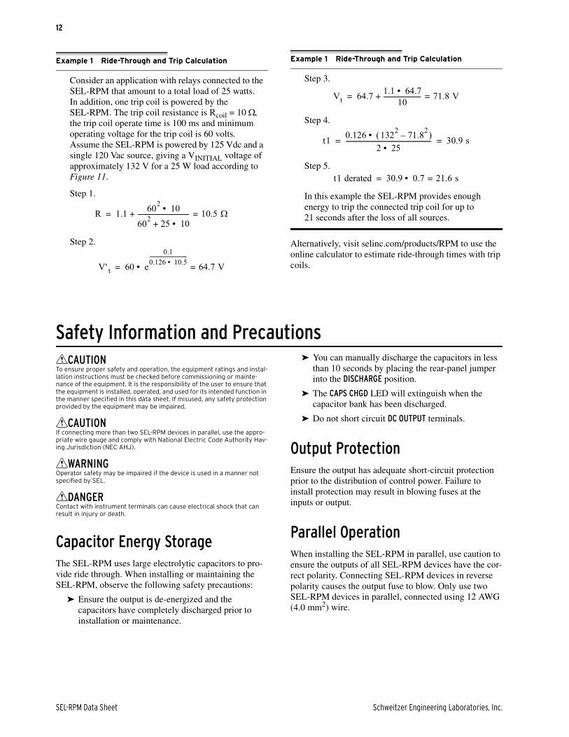
Safety Information and PrecautionsCAUTION
To ensure proper safety and operation, the equipment ratings and instal-lation instructions must be checked before commissioning or mainte-nance of the equipment. It is the responsibility of the user to ensure that the equipment is installed, operated, and used for its intended function in the manner specified in this data sheet. If misused, any safety protection provided by the equipment may be impaired.
CAUTIONIf connecting more than two SEL-RPM devices in parallel, use the appro-priate wire gauge and comply with National Electric Code Authority Hav-ing Jurisdiction (NEC AHJ).
WARNINGOperator safety may be impaired if the device is used in a manner not specified by SEL.
DANGERContact with instrument terminals can cause electrical shock that can result in injury or death.
Capacitor Energy StorageThe SEL-RPM uses large electrolytic capacitors to pro-vide ride through. When installing or maintaining the SEL-RPM, observe the following safety precautions:
➤ Ensure the output is de-energized and the capacitors have completely discharged prior to installation or maintenance.
➤ You can manually discharge the capacitors in less than 10 seconds by placing the rear-panel jumper into the DISCHARGE position.
➤ The CAPS CHGD LED will extinguish when the capacitor bank has been discharged.
➤ Do not short circuit DC OUTPUT terminals.
Output ProtectionEnsure the output has adequate short-circuit protection prior to the distribution of control power. Failure to install protection may result in blowing fuses at the inputs or output.
Parallel OperationWhen installing the SEL-RPM in parallel, use caution to ensure the outputs of all SEL-RPM devices have the cor-rect polarity. Connecting SEL-RPM devices in reverse polarity causes the output fuse to blow. Only use two SEL-RPM devices in parallel, connected using 12 AWG (4.0 mm2) wire.
Example 1 Ride-Through and Trip Calculation
Consider an application with relays connected to the SEL-RPM that amount to a total load of 25 watts. In addition, one trip coil is powered by the SEL-RPM. The trip coil resistance is Rcoil = 10 , the trip coil operate time is 100 ms and minimum operating voltage for the trip coil is 60 volts. Assume the SEL-RPM is powered by 125 Vdc and a single 120 Vac source, giving a VINITIAL voltage of approximately 132 V for a 25 W load according to Figure 11.
Step 1.
Step 2.
R 1.1 602 10•
602 25 10• +--------------------------------- 10.5 =+=
Vt 60 e
0.10.126 10.5• ------------------------------
64.7 V=• =
Step 3.
Step 4.
Step 5.
In this example the SEL-RPM provides enough energy to trip the connected trip coil for up to 21 seconds after the loss of all sources.
Example 1 Ride-Through and Trip Calculation
Vt 64.7 1.1 64.7• 10------------------------ 71.8 V=+=
t1 0.126 1322 71.82– •
2 25• ------------------------------------------------------- 30.9 s= =
t1 derated 30.9 0.7 21.6 s=• =
SEL-RPM Data Sheet Schweitzer Engineering Laboratories, Inc.

13
Output DangerPrior to working on the output of the SEL-RPM, observe the following process to ensure that the capacitors have been fully discharged, and the output has de-energized safely.
Step 1. Disconnect all input sources.
Step 2. Verify on front of the SEL-RPM that all input LEDs are extinguished.
Step 3. On the rear panel of the SEL-RPM, move the jumper into the DISCHARGE position.
Step 4. Verify the CAPS CHGD LED is extinguished.
Step 5. Verify the outputs terminals de-energize by using the following live-dead-live process to verify your voltmeter is functioning properly:
a. (Live) Verify the voltmeter is functional on known source.
b. (Dead) Verify the SEL-RPM output is less than 30 volts.
c. (Live) Confirm the voltmeter is still func-tional on known source.
InstallationThe SEL-RPM mounts by its front vertical flanges in a cutout or a 19-inch vertical relay rack. A 1-inch space should be left directly above and below the SEL-RPM to allow for adequate convection cooling.
Connect the dc output to a fuse or a miniature circuit breaker prior to the distribution of control power (see Figure 13).
Consider adding a fuse or miniature circuit breaker upstream of the SEL-RPM input sources, depending on system configuration and application requirements. Refer to Specifications on page 15 for the SEL-RPM source fuse part numbers to aid fusing coordination.
Functional TestingThe following steps test the SEL-RPM after installation to verify that each input voltage source can power the load:
Step 1. Connect a dc load to the DC OUTPUT terminals, noting the polarity markings on the SEL-RPM and on the load.
Step 2. Connect a rated dc input source to the DC SOURCE and the rated ac input sources to AC1 SOURCE, AC2 SOURCE, and AC3 SOURCE.
Step 3. Apply dc power.
Step 4. Verify:
d. DC and DC OUTPUT LEDs illuminate.
e. DC output voltage is present by using a voltmeter.
Step 5. Disconnect DC SOURCE power and apply ac power to AC1 SOURCE.
Step 6. Verify:
a. AC1 and DC OUTPUT LEDs illuminate.
b. DC output voltage is present by using a voltmeter.
Step 7. Repeat Step 5 and Step 6 for AC2 and AC3 source.
Step 8. Remove power from all input sources.
Step 9. Verify:
a. All four input LEDs extinguish.
b. Connected load stays powered for a period of time, estimated using the connected load and voltage dropout.
Figure 13 SEL-RPM Connections
+ –SEL-RPM
DC OUTPUT
AC1 SOURCE
AC2SOURCE
AC3SOURCE
H N H N H N
To ConnectedLoads
AC Sources
1 2 3 4 5 6
11 12
Ground
13GND
DC IN
+ –
DC System
7 8
Schweitzer Engineering Laboratories, Inc. SEL-RPM Data Sheet

14
Testing Ride-Through TimeRide-through time is based on the connected load, the highest available input voltage, and the dropout voltage of connected loads, as calculated in Equation 1.
Perform the following steps to verify approximate ride-through time for the given installation:
Step 1. Apply power.
Step 2. Once all connected loads are powered, discon-nect power to the SEL-RPM.
Step 3. Start a timer when all input sources have been disconnected.
Step 4. Stop the timer when the connected load alarm contact asserts or for visual shutdown of con-nected load.
Dielectric Strength TestingYou can perform high-potential testing on the SEL-RPM ac sources. See Specifications on page 15 for dielectric strength rating.
Capacitor Discharge TestingTo verify the proper operation of the capacitor manual discharge, perform the following steps:
Step 1. Disconnect all loads from DC OUTPUT.
Step 2. Disconnect all voltage sources (DC SOURCE, AC1 SOURCE, AC2 SOURCE, and AC3 SOURCE).
Step 3. Use a voltmeter to verify that terminals DC SOURCE, AC1 SOURCE, AC2 SOURCE, and AC3 SOURCE are de-energized.
Step 4. Use a voltmeter to verify the DC OUTPUT terminal has more than 30 volts present and the CAPS CHGD LED is illuminated.
Step 5. Remove the rear-panel jumper from the OPERATE position and install in the DISCHARGE position for 10 seconds. Reinstall the jumper in the OPERATE position.
Verify that the voltage on the DC OUTPUT termi-nals is less than 30 volts and the CAPS CHGD LED is no longer illuminated.
Diagrams and Dimensions
Figure 14 SEL-RPM Front- and Rear-Panel Dimensions
18.31[465.1]
4.00[101.6]
9.28[235.8]
1.30[33.0]
19.00[482.6]
6.97[177.0]
SEL-RPM
i9388b
LEGENDin
[mm]
FRONT SIDE
TOP
SEL-RPM Data Sheet Schweitzer Engineering Laboratories, Inc.
15
Specifications
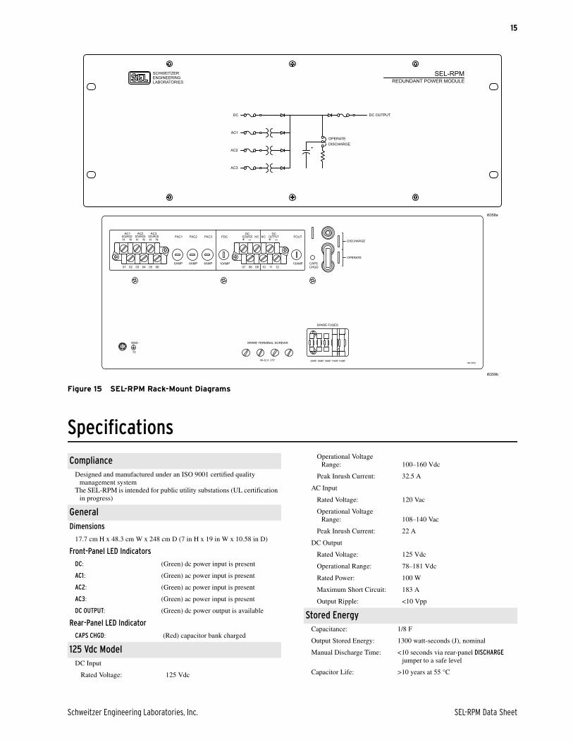
Figure 15 SEL-RPM Rack-Mount Diagrams
i6358a
SEL-RPMREDUNDANT POWER MODULE
SCHWEITZERENGINEERINGLABORATORIES
AC2
AC1
AC3
DC
+
DC OUTPUT
OPERATEDISCHARGE
GND
13
196-0052
121110090807
SOURCEAC3
SOURCEAC2
NHSOURCE
AC1
060504030201
–+OUTPUT
DCN/CN/C
–+SOURCE
DCFAC1 FAC2 FAC3 FDC FOUT
6AMP 6AMP 6AMP 10AMP 10AMP CAPSCHGD
DISCHARGE
OPERATE
6AMP 6AMP 6AMP 10AMP
SPARE FUSES
10AMP#8-32 X .375"
SPARE TERMINAL SCREWS
NH NH
i6359b
ComplianceDesigned and manufactured under an ISO 9001 certified quality
management systemThe SEL-RPM is intended for public utility substations (UL certification
in progress)
GeneralDimensions
17.7 cm H x 48.3 cm W x 248 cm D (7 in H x 19 in W x 10.58 in D)
Front-Panel LED Indicators
DC: (Green) dc power input is present
AC1: (Green) ac power input is present
AC2: (Green) ac power input is present
AC3: (Green) ac power input is present
DC OUTPUT: (Green) dc power output is available
Rear-Panel LED Indicator
CAPS CHGD: (Red) capacitor bank charged
125 Vdc ModelDC Input
Rated Voltage: 125 Vdc
Operational Voltage Range: 100–160 Vdc
Peak Inrush Current: 32.5 A
AC Input
Rated Voltage: 120 Vac
Operational Voltage Range: 108–140 Vac
Peak Inrush Current: 22 A
DC Output
Rated Voltage: 125 Vdc
Operational Range: 78–181 Vdc
Rated Power: 100 W
Maximum Short Circuit: 183 A
Output Ripple: <10 Vpp
Stored EnergyCapacitance: 1/8 F
Output Stored Energy: 1300 watt-seconds (J), nominal
Manual Discharge Time: <10 seconds via rear-panel DISCHARGE jumper to a safe level
Capacitor Life: >10 years at 55 °C
Schweitzer Engineering Laboratories, Inc. SEL-RPM Data Sheet

16
Technical SupportWe appreciate your interest in SEL products and services. If you have questions or comments, please contact us at:
Schweitzer Engineering Laboratories, Inc.2350 NE Hopkins CourtPullman, WA 99163-5603 U.S.A.Tel: +1.509.338.3838Fax: +1.509.332.7990Internet: selinc.com/supportEmail: [email protected]
Fuses125 Vdc Model
DC Input: 10 A (Schurter 8020.5021 or equivalent)
AC Input: 6 A (Bel Fuse 0654R6000-51 or equivalent)
DC Output: 10 A (Schurter 8020.5021 or equivalent)
Environmental
Operating Temperature: –40° to +85°C (–40° to +185°F)
Storage Temperature: –40° to +85°C (–40° to +185°F)
Humidity: 5% to 95% without condensation*
Maximum Altitude: 2,000 m
Pollution Degree: 2
Weight (Maximum)
20.4 kg (45 lb)
Terminal Connections
Rear Screw-Terminal Tightening Torque, #8 Ring Lug, 8-32 Thread Pitch
Minimum: 1.0 Nm (9 in-lb)
Maximum: 2.0 Nm (18 in-lb)
User terminals and stranded copper wire should have a minimum temperature rating of 105°C. Ring terminals are recommended.
Type TestsEnvironmental Tests (Exploratory)
Cold: IEC 60255-27:2013, Section 10.6.1.2Test Ad:16 hours at –40°C
Damp Heat Cyclic: IEC 60255-27:2013, Section 10.6.1.6 Test Db: 25° to 55°C, 6 cycles, 95% humidity
Dry Heat: IEC 60255-27:2013, Section 10.6.1.1 Test Bd:16 hours at +85°C
Vibration: IEC 60255-27:2013, Section 10.6.2.1 Severity Level: Class 2 (endurance); Class 2 (response)
IEC 60255-27:2013, Section 10.6.2.2Severity Level: Class 1 (shock withstand, bump); Class 2 (shock response)
IEC 60255-27:2013, Section 10.6.2.4Severity Level: Class 2 (quake response)
Safety
Dielectric Strength: IEC 60255-27:2013, Section 10.6.4.33,100 Vdc: ac inputs to chassis, dc input to chassis, dc output to chassis
Note: DC input is not isolated from the dc output.
Impulse: IEC 60255-27:2013, Section 10.6.4.20.5 J, 5 kV
Object Penetration: Front: IEC 60255-27:2013, Section 10.6.2.6Protection Class: IP3X
Rear: IEC 60255-27:2013, Section 10.6.2.6Protection Class: IP2X
© 2020 by Schweitzer Engineering Laboratories, Inc. All rights reserved.
All brand or product names appearing in this document are the trademark or registered trademark of their respective holders. No SEL trademarks may be used without written permission. SEL products appearing in this document may be covered by U.S. and Foreign patents.
Schweitzer Engineering Laboratories, Inc. reserves all rights and benefits afforded under federal and international copyright and patent laws in its products, including without lim-itation software, firmware, and documentation.
The information in this document is provided for informational use only and is subject to change without notice. Schweitzer Engineering Laboratories, Inc. has approved only the English language document.
This product is covered by the standard SEL 10-year warranty. For warranty details, visit selinc.com or contact your customer service representative.
*PDSRPM-01*
2350 NE Hopkins Court • Pullman, WA 99163-5603 U.S.A.Tel: +1.509.332.1890 • Fax: +1.509.332.7990selinc.com • [email protected]
SEL-RPM Data Sheet Date Code 20201022