Embed Size (px)
Citation preview

SJKSJKSJKSJK Product BrochureProduct BrochureSEJIN P & S KOREA Co., Ltd.SEJIN P & S KOREA Co., Ltd.
www.sejin-piping.com

how to order .......................................................................................... 4-5
Quality Control ............................................................................................ 5
Pipets® ................................................................................................... 6-18
Bossets® ............................................................................................. 19-21
Vesselets® ........................................................................................... 22-24
Special tees .............................................................................................. 25
Wyes and laterals ..................................................................................... 26
Specialty Products ............................................................................... 27-28
Flanges ..................................................................................................... 29
Consolidation Charts ........................................................................... 30-32
tablE of contEntS

how to order Branch connectionS/wFi PiPetS
1. specify run or Header size (for consolidated run sizes see pages 30-32) 2. specify Branch/outlet size 3. specify class, schedule or thickness:
• Socket-weld & threaded Branches: Specify Header Size, Branch Size and Class (3000, 6000 & 9000) • Buttweld Branches: Specify Schedule or thickness for both header and branch pipes: Std, xS, S160 etc.
4. specify Branch style
Pipet®
Buttweld Pipet® (BWP) threaded Pipet® (thP) Socketweld Pipet® (SWP) BW/SW/thd elbo Pipet®
(BeP, SeP, teP) BW/SW/thd lateral Pipet®
(BlP, SlP, tlP)
5. select Material specification
• Carbon Steel - Sa/a105, Sa/a105n, Sa/a350-lF2 Class___, etc. • Stainless Steels: Sa/a 182 F304l, F316l, F347, F321, F317/l, etc. • Chrome moly: Sa/a182 F11 Class___, F22 Class___, F5, F9, F91, etc. • other: High yield, nickel/nickel alloys, Copper nickel, nickel Copper, Duplex, 6 moly, Super duplex, titanium, etc.

butt-WEld pipEt®
SA/A105 & SA/A350 LF2 CL1
Butt-weLd
ScheduLe 160
xxS
1/2 1-1/8 1-1/4 0.464 0.243/4 1-1/4 1-1/2 0.612 0.391 1-1/2 1-3/4 0.815 0.621-1/4 1-3/4 2-1/4 1.160 1.161-1/2 2 2-3/4 1.338 1.802 2-3/16 3 1.689 2.292-1/2 2-7/16 4 2.125 3.023 2-7/8 4-7/16 2.624 6.344 3-5/16 5 -3/8 3.438 9.946 4-1/8 8-1/2 5.187 25.25
dimensions
A B C*Outlet Size
Inches
Sche
dule
160
Appx. Weight Pounds
each outlet size listed is available to fit any run curvature. Bw ends per B16.9 and B16.25. design per Mss-sP-97.
run PiPe SizeS outlet sizes 6" and less fit a number of run pipe sizes, and the fittings are marked accordingly. See page 30 for Pipet Consolidation Chart. SCheduleS Pipe schedule numbers and weight designations are in accordance with aSMe B36.10.FlatS a flat Butt-Weld Pipet fitting for use on welding caps, elliptical heads and flat surfaces is available.ordering When ordering a fitting, see page 4.
although every attempt has been made to insure that the information contained in these tables is correct, WFI reserves the right to change the “B” and “C” dimensions as deemed necessary.
*the "C" dimension represents the waterway dimension of the fitting and does not include the minimal taper and radius required for manufacturing purposes. installation holes in header should be based on actual fittings.
1/2 1-1/8 1-1/4 0.252 0.233/4 1-1/4 1-1/2 0.434 0.651 1-1/2 1-3/4 0.599 0.781-1/4 1-3/4 2-1/4 0.896 1.161-1/2 2 2-3/4 1.100 1.602 2-3/16 3 1.503 2.462-1/2 2-7/16 4 1.771 3.023 2-7/8 4-7/16 2.300 6.914 3-5/16 5 -3/8 3.152 11.006 4-1/8 8-1/2 4.897 32.94
dimensions
A B C*Outlet Size
Inches
XXS
Appx. Weight Pounds

thrEadEd pipEt®
SA/A105 & SA/A350 LF2 CL1
threaded cL 3000
cL 6000
1/4 3/4 1-1/16 .437 0.143/8 13/16 1-1/16 .563 0.141/2 1 1-15/32 .718 0.283/4 1-1/16 1-45/64 .922 0.391 1-5/16 2-3/32 1.156 0.731-1/4 1-5/16 2-17/32 1.500 0.961-1/2 1-3/8 2-25/32 1.734 1.122 1-1/2 3-5/16 2.218 1.662-1/2 1-13/16 3-29/32 2.625 2.733 2 4-21/32 3.250 3.884 2-1/4 5-13/16 4.250 6.18
dimensions
A B C*Outlet Size
Inches CL
300
0
1/4 3/4 1-1/16 .437 0.143/8 1-1/8 1-5/16 .563 0.141/2 1-1/4 1-3/4 .718 0.283/4 1-7/16 2-1/16 .922 0.391 1-9/16 2-17/32 1.156 0.731-1/4 1-5/8 2-1/2 1.484 0.961-1/2 1-11/16 3-5/16 1.734 1.122 2-1/16 3-31/32 2.218 1.66
dimensions
A B C*Outlet Size
Inches
CL 6
000
Appx. Weight Pounds
Appx. Weight Pounds
each outlet size listed is available to fit any run curvature. threaded ends are in accordance with ansI/asMe B1.20.1 design per Mss-sP-97.
run PiPe SizeS outlet sizes noted above fit a number of run pipe sizes, and the fittings are marked accordingly. See page 30 for Pipet Consolidation Chart.FlatS a flat threaded Pipet for use on welding caps, elliptical heads and flat surfaces is available.ordering When ordering a fitting, see page 4.
although every attempt has been made to insure that the information contained in these tables is correct, WFI reserves the right to change the “B” and “C” dimensions as deemed necessary.
*the "C" dimension represents the waterway dimension of the fitting and does not include the minimal taper and radius required for manufacturing purposes. installation holes in header should be based on actual fittings.

Socket weLd
cL 3000
cL 6000
SockEt-WEld pipEt®
SA/A105 & SA/A350 LF2 CL1
1/4 3/4 1 0.364 3/8 0.143/8 13/16 1-1/16 0.493 7/16 0.141/2 1 1-15/32 0.622 9/16 0.283/4 1-1/16 1-45/64 0.824 9/16 0.391 1-5/16 2-3/32 1.049 25/32 0.731-1/4 1-5/16 2-17/32 1.38 23/32 0.961-1/2 1-3/8 2-25/32 1.61 3/4 1.122 1-1/2 3-5/16 2.067 13/16 1.662-1/2 1-13/16 3-29/32 2.469 3/4 2.733 2 4-21/32 3.068 15/16 3.884 2-1/4 5-13/16 4.026 1-1/16 6.60
dimensions
A B C* EOutlet Size
Inches
1/2 1-1/4 1-3/4 0.464 13/16 0.283/4 1-7/16 2-1/16 0.612 15/16 0.391 1-9/16 2-17/32 0.815 1-1/32 0.731-1/4 1-5/8 2-1/2 1.160 1-1/32 0.961-1/2 1-5/8 3-5/16 1.338 1-1/16 1.632 2-1/16 3-31/32 1.687 1-3/8 1.66
dimensions Outlet Size Inches
CL 3
000
CL 6
000
Appx. Weight Pounds
Appx. Weight Pounds
A B C* E
each outlet size listed is available to fit any run curvature. socket dimensions are in accordance with asMe B16.11. design per Mss-sP-97.
run PiPe SizeS outlet sizes noted above fit a number of run pipe sizes, and the fittings are marked accordingly. See page 30 for Pipet Consolidation Chart.FlatS a flat Socket-Weld Pipet for use on welding caps, elliptical heads and flat surfaces is available.ordering When ordering a fitting, see page 4.
although every attempt has been made to insure that the information contained in these tables is correct, WFI reserves the right to change the “B” and “C” dimensions as deemed necessary.
*the "C" dimension represents the waterway dimension of the fitting and does not include the minimal taper and radius required for manufacturing purposes. installation holes in header should be based on actual fittings.

butt-WEld pipEt®
STAInLeSS & ALLOy
Butt-weLd
Standard weight
extra Strong
3/8 3/4 1 0.493 0.091/2 3/4 1-1/8 0.622 0.123/4 7/8 1-1/2 0.824 0.281 1-1/16 1-3/4 1.049 0.341-1/4 1-1/4 2-1/4 1.38 0.721-1/2 1-5/16 2-1/2 1.610 0.902 1-1/2 3 2.067 1.122-1/2 1-5/8 3-1/2 2.469 2.313 1-3/4 4 3.068 2.504 2 5 4.026 5.896 2-3/8 7-1/2 6.065 10.50
dimensions
A B COutlet Size
Inches
Stan
dard
Appx. Weight Pounds
each outlet size listed is available to fit any run curvature. Bw ends per B16.9 and B16.25. design per Mss-sP-97.
run PiPe SizeS outlet sizes 6" and less fit a number of run pipe sizes, and the fittings are marked accordingly. See page 31 for Pipet Consolidation Chart. SCHeDUleS Standard Weight Fittings are the same as schedule 40 fittings through 10". a schedule 40 Butt-Weld Pipet for sizes 12" and larger is available. dimensions and prices on application. extra Strong Fittings are the same as schedule 80 fittings through 8". a schedule 80 Butt-Weld Pipet for sizes 10" and larger is available. dimensions and prices on application. Pipe schedule numbers and weight designations are in accordance with aSMe B36.10.FlatS a flat Butt-Weld Pipet fitting for use on welding caps, elliptical heads and flat surfaces is available.ordering When ordering a fitting, see page 4.
although every attempt has been made to insure that the information contained in these tables is correct, Bonney Forge reserves the right to change the “B” and “C” dimensions as deemed necessary.
3/8 3/4 1 0.423 0.151/2 3/4 1-1/8 0.546 0.123/4 7/8 1-1/2 0.742 0.211 1-1/16 1-3/4 0.957 0.431-1/4 1-1/4 2-1/4 1.278 0.691-1/2 1-5/16 2-1/2 1.500 0.892 1-1/2 3 1.939 1.252-1/2 1-5/8 3-1/2 2.323 2.633 1-3/4 4 2.900 3.824 2 5 3.826 6.176 3-1/16 7-1/2 5.761 15.06
dimensions A B C
Outlet Size Inches
Extra
Stro
ng
Appx. Weight Pounds

1/4 3/4 7/8 .438 0.143/8 13/16 1 .563 0.141/2 1 1-1/4 .703 0.283/4 1-1/16 1-1/2 .906 0.391 1-5/16 1-7/8 1.141 0.731-1/4 1-5/16 2-1/4 1.484 0.961-1/2 1-3/8 2-1/2 1.719 1.122 1-1/2 3 2.188 1.66
1/4 3/4 1 .438 0.143/8 1-1/8 1-1/4 .563 0.141/2 1-1/4 1-1/2 .703 0.283/4 1-7/16 1-3/4 .906 0.391 1-9/16 2-1/4 1.141 0.731-1/4 1-5/8 2-1/2 1.484 0.961-1/2 1-11/16 3 1.719 1.632 2-1/16 3-5/8 2.188 1.66
each outlet size listed is available to fit any run curvature. threaded ends are in accordance with ansI/asMe B1.20.1 design per Mss-sP-97.
run PiPe SizeS outlet sizes noted above fit a number of run pipe sizes, and the fittings are marked accordingly. See page 31 for Pipet Consolidation Chart.FlatS a flat threaded Pipet for use on welding caps, elliptical heads and flat surfaces is available.ordering When ordering a fitting, see page 4.
although every attempt has been made to insure that the information contained in these tables is correct, WFI reserves the right to change the “B” and “C” dimensions as deemed necessary.
thrEadEd pipEt®
STAInLeSS & ALLOy
threaded
cL 3000
cL 6000 dimensions
A B COutlet Size
Inches CL
300
0
Appx. Weight Pounds
dimensions A B C
Outlet Size Inches
CL 6
000
Appx. Weight Pounds

each outlet size listed is available to fit any run curvature. socket dimensions are in accordance with asMe B16.11. design per Mss-sP-97.
run PiPe SizeS outlet sizes noted above fit a number of run pipe sizes, and the fittings are marked accordingly. See page 31 for Pipet Consolidation Chart.FlatS a flat Socket-Weld Pipet for use on welding caps, elliptical heads and flat surfaces is available.ordering When ordering a fitting, see page 4.
although every attempt has been made to insure that the information contained in these tables is correct, WFI reserves the right to change the “B” and “C” dimensions as deemed necessary.
SockEt-WEld pipEt®
STAInLeSS & ALLOy
Socket weLd
cL 3000
cL 6000
1/4 3/4 7/8 0.364 3/8 0.143/8 13/16 1-1/16 0.493 7/16 0.141/2 1 1-1/4 0.622 9/16 0.283/4 1-1/16 1-1/2 0.824 9/16 0.391 1-5/16 1-7/8 1.049 25/32 0.731-1/4 1-5/16 2-1/4 1.38 23/32 0.961-1/2 1-3/8 2-1/2 1.61 3/4 1.122 1-1/2 3 2.067 13/16 1.66
1/2 1-1/4 1-3/8 .464 13/16 0.283/4 1-7/16 1-3/4 .612 15/16 0.391 1-9/16 2 .815 1-1/32 0.731-1/4 1-5/8 2-1/2 1.16 1-1/32 0.961-1/2 1-11/16 2-3/4 1.338 1-1/16 1.632 2-1/16 3-3/8 1.687 1-3/8 1.66
CL 6
000
Outlet Size Inches
dimensions Appx. Weight Pounds
CL 3
000
Outlet Size Inches
dimensions Appx. Weight Pounds A B C E
A B C E

lightWEight SchEdulE 10S, lW, and cl300 pipEtS®
Butt-weLd
threaded
Socket weLd
*Branch dimensions are in accordance with aSMe B16.11 Cl 3M.
Benefits• reduces Welding reduces weld volume and
welding time by more than 50% compared to traditional designs.
• reduces Header Weld Cross Section allows full penetration groove welds without “suck in” or distortion.
• reduces Heat Build Up reduces run pipe heat distortion.
• Is Used on all run pipe thicknesses (Cl300) S5s/10s & lW design can be used with any schedule or thickness run pipe in B16.5 Class 150 & Class 300 piping systems.
• meets piping Codes & Standards Burst tests, markl Fatigue tests, Finite element analysis, mSS- Sp-97, aSme B31.1 & B31.3, aSme/anSI B16.9 & B16.11.
IdentificationSpecify Butt-Weld as follows: light Wall x Branch Schedule: 10" lW x 2" S10s run Schedule x Branch Schedule: 10" S10s x 2" S10s Cl300 x Branch Schedule: 10" Cl300 x 2" Std Wt*
Specify Socket-Weld & Threaded as follows:light Wall x Branch Class: 10" lW x 2" Cl 3M SWPrun Wall x Branch Class: 10" S10s x 2" Cl 3M thd 10" S40s x 2" Cl 3M SWP S10s
Cl300 x Branch Class: 10" Cl300 x 2" Cl 3M thd
*Fittings designated Cl300 can be installed on any run pipe thickness (S10s, Std, xS, S160, xxS) in B16.5 Class 150 or Class 300 Piping Systems.
**to obtain S10s/lW/Cl300 design for run pipes thicker than S10s, either lW or Cl300 must be specified.
note: although every attempt has been made to insure that the information contained in these tables is correct, WFI reserves the right to change the “C” dimension as deemed necessary.
See page 32 for consolidation chart.
Outlet Size
Inches
BUTT-WELd ThREAdEd* SOCkET WELd
dimensionsAppx. Wt/Lb
dimensionsAppx. Wt/Lb
dimensionsAppx. Wt/Lb A C A C A
C3m 5s 10s
C = id of
specified branch
pipe
3M provided unless
otherwise specified
1/2 3/4 0.10 1 0.703 0.25 1 0.622 0.710 0.674 0.243/4 7/8 0.23 1-1/16 0.906 0.35 1-1/16 0.824 0.920 0.884 0.341 1-1/16 0.26 1-5/16 1.141 0.65 1-5/16 1.049 1.185 1.097 0.631-1/2 1-5/16 0.78 1-3/8 1.719 0.92 1-3/8 1.610 1.770 1.682 0.912 1-1/2 0.89 1-1/2 2.188 1.40 1-1/2 2.067 0.703 2.157 1.373 1-3/4 2.274 2 4.376 2-3/8 10.19
latEral pipEt®
45° connectionS
Forged
45° BRANCh CONNECTIONS ThREAdEd, SOCkET-WELd ANd BUTT-WELd ENdS
also available for run sizes through 36". See footnotes at bottom of page 15.
Nominal Run Pipe
Size
Outlet Size
dimensionsCL 3000 Threaded and Socket-Weld
CL 6000 Threaded and Socket-Weld
STd & XS Butt-Weld
Sch. 160 and XXS Butt-Weld
E E E E2-1/2 - 1-1/4 12 - 3 1/4 1-9/16 1-9/16 1-9/16
2-1/2 - 1-1/4 12 - 3 3/8 1-9/16 1-9/16 1-9/16
2-1/2 - 1-1/4 12 - 3 1/2 1-9/16 1-15/16 1-9/16 1-7/8
1-1/2 - 1-1/4 5 - 2 12 - 6
3/4 1-15/162-1/4 2-1/4
2-5/161-15/16 2-1/8
2-1/2 - 2 5 - 3 12 - 6
12-1/4 2-1/4
2-5/162-1/2
2-1/4 2-1/4
2-5/162-7/16
2-1/2 - 2 5 - 3 12 - 6
1-1/4 2-1/2 2-11/16 2-1/2 2-15/16
2-1/2 - 2 5 - 3 12 - 6
1-1/2 2-11/16 3-3/16 2-11/16 3-1/4
5 - 4 8 - 6 12 - 10
2 3-3/16 3-7/16
order to Specific run Pipe
Sizes
3
4

Elbo pipEt®
90° Long radiuS
Forged
fOR ELBOW OUTLETS ThREAdEd, SOCkET-WELd ANd BUTT-WELd ENdS
footnotes applying to the elbo Pipet and lateral Pipet:Socket dimensions to aSMe B16.11thread dimensions to anSi/aSMe B1.20.1Butt-Weld end Dimensions to aSme B16.9 & B16.25each elbo pipet 2" & smaller is uniquely designed to fit all the elbow sizes shown. the complete size range interchangeability is so marked on the fitting.**available as Butt-Weld outlets only. larger sizes available - Std/xS/S160/xxS.
ordering When ordering fittings - see page 4.
although every attempt has been made to insure that the information contained in these tables is correct, WFI reserves the right to change dimensions as deemed necessary.
the values listed are based on long radius elbows, twice the branch size listed.
Nominal Elbow Size
Inches
Outlet SizeInches
dimensions
STd. Buttweld
XS Buttweld
CL 3000 Thd and Socketweld
CL 6000 Thd and Socketweld
E E E E
36 thru 3/4 36 thru 1
1/2 3/4
1-3/8 1-11/16
1-3/8 1-11/16
1-19/32 1-7/8
1-7/8 2-1/4
36 thru 2 36 thru 2
1 1-1/4
1-15/16 2-1/8
1-15/16 2-1/8
2-1/4 2-1/2
2-1/2 2-11/16
36 thru 2 36 thru 2
1-1/2 2
2-5/16 2-3/4
2-5/16 2-3/4
2-11/16 3-1/4
3-1/4
order to Specific elbow Sizes
**2-1/2 **3 **4
3-3/16 3-1/2 4-5/16
3-3/16 3-1/2 4-5/16
** **
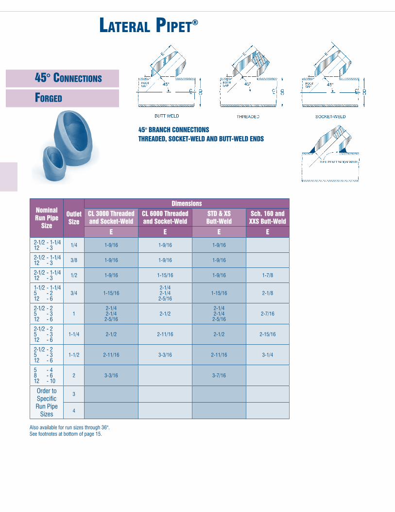
nipplE pipEt®
PLain end
threaded end
*available in lengths 4 1/2", 5 1/2" and 6 1/2"Weights based on Carbon Steel (.283 lbs/in3)
ordering When ordering fittings - see page 4.
although every attempt has been made to insure that the information contained in these tables is correct, WFI reserves the right to change the “C” dimension as deemed necessary.
integrally reinforced branch connection of one piece construction which eliminates costly welds and provides convenience of socket-weld and threaded ends for valves and instruments. available in standard lengths of 3 1/2" and 6 1/2". Special lengths on request.
Thre
aded
& P
lain
End
Outlet Size Inches
dimensions Appx. Weight PoundsA*
BS/80 S/160 XXS
1/2 3-1/2 0.546 0.464 0.252 0.45
3/4 3-1/2 0.742 0.612 0.434 0.64
1 3-1/2 0.957 0.815 0.599 0.92
1-1/4 3-1/2 1.278 1.160 0.896 1.40
1-1/2 3-1/2 1.500 1.338 1.100 1.72
2 3-1/2 1.939 1.687 1.503 2.50
Thre
aded
& P
lain
End
Outlet Size Inches
dimensions Appx. Weight PoundsA*
CS/80 S/160 XXS
1/2 3-1/2 0.464 0.464 0.252 0.45
3/4 3-1/2 0.612 0.612 0.434 0.64
1 3-1/2 0.815 0.815 0.599 0.92
1-1/4 3-1/2 1.160 1.160 0.896 1.40
1-1/2 3-1/2 1.338 1.338 1.100 1.72
2 3-1/2 1.687 1.687 1.503 2.50

flangEd pipEt®
overview
elIMInate welds!
don’t waste time and money making 3 welds... when the single weld wfI® flanged Pipet® performs better!
forged one-PIece constructIon Means less weldIng.
WFI Flanged pipets are available in any length, material, pipe wall thickness and flange rating.
WFI Flanged pipets offer a simplified installation and provide more exacting tolerances where multiple flanges of constant height are required.
one-piece construction eliminates two extra stress points and the clean, seamless bore of-fers better performance. the base is contoured for attachment to a pipe, elbow or vessel.
rF, rtJ and other standard flanged faces are available.
• excellent choice for hot tap applications. (When specified, hot tap configurations will be supplied.)
• Integrally reinforced, weld-on connection.• exclusive design distributes stress more evenly and removes flow interruptions.• available in all sizes, heights, wall thicknesses, and materials.
ordering inFormation
Specify:• Header Size and Schedule• outlet Size and Schedule• Flange rating and Bore• Face Style (rF, rtJ, etc.)• Design Standard (aSme B16.5 unless otherwise requested)
Example: 6" Std. Wt. x 2" 300# RF S80 Bore
avaIlaBle In all forgIng-qualIty MaterIals.
OLd mEThOdBranch Connection–
Pipe-Weld Neck flange
NEW mEThOdWfI® flanged Pipet®

flangEd pipEt®
noteS: Flange dimensions and tolerances are in accordance with published flange standards (aSMe B16.5, aPi6a, etc.) available in all standard facingsoutlet sizes greater than 2" nPs are available upon request.“a” dimensions other than 6" are available upon request.Flange thickness for Class 150 and Class 300 include 1/16" raised face.Flange thickness for Class 600, 1500 and 2500 does not include 1/4" raised face.available under Mil-i-45208 and aSMe Section iii Quality Programs.
*For 1500 and 2500 Class when used as a lateral pipet or elbo pipet, the flange diameter may cause interference with the run pipe. For that reason in these products, WFI offers a standard “a” dimension of 9". if a shorter “a” dimension is required, it is recommended that you contact WFI.
cL 150
cL 300
cL 400 & 600
cL 900 & 1500
cL 2500
elBo-FlangeD pIpet45° FlangeD pIpet
CL 2
500
CL 9
00 &
150
0CL
400
& 6
00CL
300
Outlet flange flange Bolt No. Bolt Size A O.d. Thk. Circle of holes hole
1/2 6 3.50 .44 2.38 4 .62 3/4 6 3.88 .50 2.75 4 .62 1 6 4.25 .56 3.12 4 .62 1 1/4 6 4.62 .62 3.50 4 .62 1 1/2 6 5.00 .69 3.88 4 .62 2 6 6.00 .75 4.75 4 .75 1/2 6 3.75 .56 2.62 4 .62 3/4 6 4.62 .62 3.25 4 .75 1 6 4.88 .69 3.50 4 .75 1 1/4 6 5.25 .75 3.88 4 .75 1 1/2 6 6.12 .81 4.50 4 .88 2 6 6.50 .88 5.00 8 .75 1/2 6 3.75 .56 2.62 4 .62 3/4 6 4.62 .62 3.25 4 .75 1 6 4.88 .69 3.50 4 .75 1 1/4 6 5.25 .81 3.88 4 .75 1 1/2 6 6.12 .88 4.50 4 .88 2 6 6.50 1.00 5.00 8 .75 1/2 6* 4.75 .88 3.25 4 .88 3/4 6* 5.12 1.00 3.50 4 .88 1 6* 5.88 1.12 4.00 4 1.00 1 1/4 6* 6.25 1.12 4.38 4 1.00 1 1/2 6* 7.00 1.25 4.88 4 1.12 2 9 8.50 1.50 6.50 8 1.00 1/2 6* 5.25 1.19 3.50 4 .88 3/4 6* 5.50 1.25 3.75 4 .88 1 6* 6.25 1.38 4.25 4 1.00 1 1/4 6* 7.25 1.50 5.12 4 1.12 1 1/2 9 8.00 1.75 5.75 4 1.25 2 9 9.25 2.00 6.75 8 1.12
CL 1
50

boSSEt®
• Designed in accordance with anSI B16.11• available in Class 3000-6000-9000-10000• available in over 60 different materials• a weld-on connection in socket-weld, threaded or combination threaded and socket-weld designs• Forty different designs and combinations available. please contact WFI for further details or visit our
web site at www.wfi-intl.com.
B-1 BoSSet Combination Socket-Weld & Threaded Boss
3000 LB 6000 LB
Outlet Size
dN 15 20 25 32 40 50 NPS 1/2 3/4 1 1 1/4 1 1/2 2MM 38.1 50.8 50.8 50.8 50.8 63.5 in 1 1/2 2 2 2 2 2 1/2 MM 17.9 23.4 29.4 37.7 43.7 56.0 in 45/64 59/64 1 5/32 1 31/64 1 23/32 2 13/64
A
h
B-1-F BoSSet Combination Socket-Weld & Threaded Insert Type Boss
PLug for Combination Socket-Weld & Threaded Boss
B-2 BoSSet Socket-Weld Boss
3000 LB 6000 LB
Outlet Size
dN 15 20 25 32 40 50 NPS 1/2 3/4 1 1 1/4 1 1/2 2MM 40 65.1 65.1 65.1 65.1 63.5 in 1 1/2 2 2 2 2 2 1/2 MM 65.1 65.1 65.1 65.1 65.1 85.7 in 2 2 2 2 2 3 3/8
BranCh PiPe i.d.
A 3000 LB
A 6000 LB
h
3000 LB 6000 LB
Outlet Size
dN 15 20 25 32 40 50 NPS 1/2 3/4 1 1 1/4 1 1/2 2MM 38.1 50.8 50.8 50.8 50.8 63.5 in 1 1/2 2 2 2 2 2 1/2 MM 17.9 23.4 29.4 37.7 43.7 56.0 in 45/64 59/64 1 5/32 1 31/64 1 23/32 2 13/64
3000 LB 6000 LB
Outlet Size
dN 15 20 25 32 40 50 NPS 1/2 3/4 1 1 1/4 1 1/2 2MM 44.5 46.0 52.4 52.4 52.4 65.1 in 1 3/4 1 13/16 2 1/16 2 1/16 2 1/16 2 9/16 MM 21.3 26.7 33.4 42.2 48.3 60.3 in .840 1.050 1.315 1.660 1.900 2.375
A
h
A
h

boSSEt®
• Designed in accordance with anSI B16.11• available in Class 3000-6000-9000-10000• available in over 60 different materials• a weld-on connection in socket-weld, threaded or combination threaded and socket-weld designs• Forty different designs and combinations available. please contact WFI for further details or visit our
web site at www.wfi-intl.com.
B-3 BoSSet Threaded Boss
3000 LB 6000 LB
Outlet Size
dN 15 20 25 32 40 50 NPS 1/2 3/4 1 1 1/4 1 1/2 2MM 38.1 50.8 50.8 50.8 50.8 63.5 in 1 1/2 2 2 2 2 2 1/2 MM 17.9 23.4 29.4 37.7 43.7 56.0 in 45/64 59/64 1 5/32 1 31/64 1 23/32 2 13/64
A
h
B-4 BoSSet Threaded Boss with Weld Ring
B-5 BoSSet Threaded Thermowell Boss
B-6 BoSSet Socket-Weld Boss with Weld Ring
3000 LB 6000 LB
Outlet Size
dN 15 20 25 32 40 50 NPS 1/2 3/4 1 1 1/4 1 1/2 2MM 33.3 34.9 42.9 47.6 50.8 57.2 in 1 5/16 1 3/8 1 11/16 1 7/8 2 2 1/4 MM 23.8 27.0 33.3 42.9 49.2 61.9 in 15/16 1 1/16 1 5/16 1 11/16 1 15/16 2 7/16
A
E
3000 LB 6000 LB
Outlet Size
dN 15 20 25 32 40 50 NPS 1/2 3/4 1 1 1/4 1 1/2 2MM 47.6 50.8 60.3 66.7 79.4 85.7 in 1 7/8 2 2 3/8 2 5/8 3 1/8 3 3/8 MM 25.4 30.2 36.5 44.5 50.8 63.5 in 1 1 3/16 1 7/16 1 3/4 2 2 1/2
A
E
3000 LB 6000 LB
Outlet Size
dN 15 20 25 32 40 50 NPS 1/2 3/4 1 1 1/4 1 1/2 2MM 33.3 34.9 42.9 47.6 50.8 57.2 in 1 5/16 1 3/8 1 11/16 1 7/8 2 2 1/4 MM 23.8 27.0 33.3 42.9 49.2 61.9 in 15/16 1 1/16 1 5/16 1 11/16 1 15/16 2 7/16
A
E

boSSEt®
• Designed in accordance with anSI B16.11• available in over 60 different materials• a weld-on connection in socket-weld, threaded or combination threaded and socket-weld designs• Forty different designs and combinations available.
B-11 BoSSet Threaded drill-Thru Extended Boss
3000 LB 6000 LB
Outlet Size
dN 15 20 25 32 40 50 NPS 1/2 3/4 1 1 1/4 1 1/2 2MM 47.6 50.8 60.3 66.7 79.4 85.7 in 1 7/8 2 2 3/8 2 5/8 3 1/8 3 3/8 MM 5.6 9.5 15.1 22.2 26.2 35.7 in 7/32 3/8 19/32 7/8 1 1/32 1 13/32
A
f
B-12 BoSSet Socket-Weld drill-Thru Extended Boss
B-13 BoSSet Combination Socket-Weld & Threaded drill-Thru Extended Boss
acceSS hoLe x-ray PLugS
3000 LB 6000 LB
Outlet Size
dN 15 20 25 32 40 50 NPS 1/2 3/4 1 1 1/4 1 1/2 2MM 47.6 50.8 60.3 66.7 79.4 85.7 in 1 7/8 2 2 3/8 2 5/8 3 1/8 3 3/8 MM 5.6 9.5 15.1 22.2 26.2 35.7 in 7/32 3/8 19/32 7/8 1 1/32 1 13/32
3000 LB 6000 LB
Outlet Size
dN 15 20 25 32 40 50 NPS 1/2 3/4 1 1 1/4 1 1/2 2MM 47.6 50.8 60.3 66.7 79.4 85.7 in 1 7/8 2 2 3/8 2 5/8 3 1/8 3 3/8 MM 5.6 9.5 15.1 22.2 26.2 35.7 in 7/32 3/8 19/32 7/8 1 1/32 1 13/32
A
f
A
f
h = Customer Specified length
1" (25) For pipe wall thickness over 1 3/8" (34.9 - 76.2) 1 1/2" (40) For pipe wall thickness over 3" - 5" (76.2 - 127.0) 2" (50) For pipe wall thickness over 5" (127.0)
1" (25) For pipe wall thickness 5/8" - 1 3/8" (15.9 - 34.9)

VESSElEt®
overview
tHe vesselet Is a contoured Integrally reInforced Insert BrancH connectIon
wHen do you sPecIfy a vesselet®?
When you need: • Fully interpretable radiographic or ultrasonic weld examination• longer life under cyclic fatigue loading• an insert fitting that is fully engineered and supported by Markl fatigue tests, burst tests, finite element analysis and years of successful experience in actual service
features of tHe vesselet®
• true butt-weld installation in header• outlets available in butt-weld, socket-weld, threaded & flanged configurations• designed for easy installation• low stress intensification factor (sif)• available in outlet size range to 60”• available in over 60 different alloys• meets all the requirements of the applicable codes & standards
Butt-weld for ease of NdT or inservice inspection
Welds directly into header or vessel for total integral type construction
ordering inFormation
required for all Codes:
1. Header (run) size & schedule or wall thickness2. outlet size & schedule or wall thickness3. Material4. quantity
Note: In the absence of any other information, WFI will supply fittings proven by burst test. Applicable codes are B131.1, B31.3 & ASME III
For aSme VIII, aSme Sec. 1, B31.4 & 8, additional service conditions are required. this enables WFI to insure that the Vesselet® provided meets the code requirements. these codes do not accept product line proof testing. they, as well as some speci-fications, require area replacement as proof of adequacy. these requirements are project specific and require additional ordering information as listed below.
1. design code2. design temperature3. design pressure4. corrosion allowance (if applicable)

VESSElEt®
conFigurationS
SizeS, weightS & dimenSionS
LATERAL & ELBO VESSELETS®
integrally reinforced, contoured-insert type branch connection ideally suited for cyclical and high pres-sure/temperature services. Patented design reduces weld volume, and lends itself to non-destructive examination. May be used to replace seamless re-ducing laterals. available in butt-weld, socket-weld, threaded, and flanged configurations.
ThERmALET®
integrally reinforced contoured-insert type branch connections, threaded (class 3000 and class 6000) and flanged (class150 thru class 2500) for thermowells in heavily insulated pipes. Moves attachment weld away from instrument tap. Patented design reduces weld volume, and lends itself to non-destructive examination.
fLANGEd VESSELET®
integrally reinforced contoured insert type branch connections with integral flange outlet (class 150 thru class 2500). eliminates flange attachment weld. Customized projection heights available.
Special Shapes and Configurations for Problems Specific to the Piping Industrythe following patents apply: 262,397 274,549 4,438,955 282,867 4,450,613 (foreign patents also)
STUddET®
designed for mating flanges to vessels or tanks utilizing contoured insert type connection. available in all flange sizes and pressure ratings. Patented design reduces weld volume, and lends itself to non-destructive examination.
Backed by complete testing programWFI has conducted comprehensive burst tests of Vesselts®. additionally, WFI has conducted fatigue tests to offer more directly applicable data for stress intensification factor (sif) calcu-lations, which are of major importance in piping system analysis.
WFI offers full engineering capability to develop special configurations and designs, and to perform analysis of those designs using in-house finite element analysis.
1/2 1-1/4 0.803/4 1-1/4 0.901 1-1/4 1.101-1/4 1-1/4 1.301-1/2 1-3/4 1.752 1-1/2 3.193 1-11/16 6.904 2-1/16 12.036 2-11/16 24.458 3 44.1410 3-1/8 63.3312 3-5/16 98.3714 3-5/8 122.0016 3-3/4 141.9018 4-5/8 173.7020 5-1/8 208.0024 5-5/8 313.00Bu
tt-W
eld
Vess
elet
- Si
zes,
Wei
ghts
& d
imen
sion
s Outlet Size Inches
dimensions Appx. Weight Pounds A Installation Od
od’s vary by
application
“a” dimensions shown are nominal for Std x Std and xS x xS. other Schedules may vary.

SafEty rEliEf ValVE VESSElEt®
safety relief valve vesselets®
Special support nozzle designed to reduce flow induced vibrations. engineered for tem-perature, pressure and flow conditions. also considers fatigue and is designed to accom-modated stresses induced from opening and closing of the valve and seismic conditions.
Designed by WFI utilizing proven technology from aSme, WrC and SwrI.
a safety relief valve requires more from its attachment nozzle than pressure/temperature protection.
WFI’s Safety relief Valve Vesselt® (SrVV) adds protection for:
• Flow induced vibration
• Seismic loads
• reaction forces
• premature Seat failure
fIll out tHe InforMatIon Below and return to wfI for a quote:
overview
Process fill in below
line Size/Wall thickness
Steam Flow (lbs/hr)
Steam Pressure
Steam temperaturematerial
line Material
SrVV MaterialValve
Weight
Set Pressure
rated Capacity (lbs/hr)
inlet id
Weld Prep (if required)
outlet id
In order to do seismic analysis, WFI needs either the seis-mic acceleration or universal Building Code zone.
In order to analyze the reaction forces, WFI needs a sketch of your layout or the dimensions listed on the typical layout sketch (Figure 1).
A offset of Discharge elbow (24" Default) ___________________
B Height of Seat _________________
C max, min, or WFI optimizes ___________________
d elbow Schedule (S/40 Default) ___________________
E Valve lift time _________________ (from Valve Mfg. .04 sec. default)
note: default Valves are used when none are given to complete the analysis
DeFaUltS outlet nom. Size height used 3" 6" 4" 8" 6" 8" 8" 10"
srvv designed for vibration control plus Pressure/temperature and fatigue endurance

SEamlESS forgEd SpEcial tEES
overview
SEAmLESS SIzE-ON-SIzE TEE
WFI designs and manufactures Seamless tees to meet all aSme Code requirements including aSme Section I, Section III, Section VIII, aSme B31 Codes, aSme B16.9, WFI’s tees are also broadly used in apI and mSS applications.
WFI Seamless tees are ideal for high pressure process and refinery piping, subsea lines, topside manifold piping, subsea risers, steam lines and boiler piping. our manufacturing process allows us to quickly make tees with heavy walls, tees with non standard reductions, and tees in hard to find material grades.
WFI also manufactures true “Seamless” Barred and target/Cushion tees. WFI Seamless Barred tees have integral bars that are not welded into the branch. these are ideal for subsea corrosion resistant alloy tees where welding may affect material properties in heat affected zones. WFI Seamless target/Cushion tees are forged with one end of the run solid. this provides a 90 degree flow path through one end of the run and out the branch. target tees are normally provided with center to end dimensions in accordance with aSMe B16.9 dimensions for buttwelding tees for new piping installations. they can also be manufactured with center to end dimensions equal to those required for buttweld elbows to replace elbows in existing piping systems. target tees are broadly used for erosive flow conditions such as those found in topside or subsea manifolds in offshore oil and gas production.
WFI tees are available in Carbon Steel, low temp, High yield, Chrome moly, Stainless, 6 moly, Duplex, Super Duplex, nickel, nickel alloys, nickel Copper and Copper nickel.
SEAmLESS TARGET TEE

SEamlESS forgEd WyES and latEralS
During the last 5 years, WFI has invested more than $4 million in new nC/CnC machine tools and forging dies to more efficiently produce large seamless Wyes and laterals for the power and energy industries. WFI also utilizes in house programs including Finite element analysis and three-dimensional Cad/CaM to assist in the drawing, design and machining of these parts.
these investments give WFI the ability to produce fittings such as Wyes and laterals with as near as uniform wall as possible while main-taining the strength of the fitting using the pressure area method of design and finite element analysis where required. WFI understands that uniform wall thickness and smooth rounded external and internal surfaces are extremely important as they relate to both thermal stress and stresses from external forces that these parts experience in service. Seamless laterals and Wyes, used primarily in high pressure steam lines and in high pressure subsea piping are subject to high thermal and reaction stresses due to excessive section thickness compared to the mating pipe. WFI’s unique manufacturing process allows us to produce these parts with maximum radiuses and a more uniform wall thickness which results in greatly reducing these stresses.
overview
SEAmLESS REdUCING LATERAL
SEAmLESS SIzE-ON-SIzE WYE

SpEcialty productS
Swage niPPLeS*
available in hard to find material grades and in reducing sizes. designed in accordance with B16.9, B16.11 and B16.28. WFI forged shapes guaranteed to meet minimum wall thickness with no thinning.
Forged ShaPeS
WFI design provides special integral reinforcement at critical stress concentration areas. available as concentric and eccentric in all material grades. all end finishes and special reductions are available. Complies to MSS-SP-95.
StuB endS
* non Commodity items
designed in accordance with B16.9 (aSa) or MSS-SP-43. available in all sizes and material grades.
reducerS & caPS
Forged seamless concentric and eccentric reducers designed in accordance with B16.9 and MSS-SP-75. Caps available in butt-weld and threaded configurations in accordance with B16.9, B16.11, aSMe Sec i and Sec Viii. these products available in all material grades and sizes.
WFI specializes in special forgings and fittings of any shape, size or material. modern forging and machining equipment, in-house engineering and design, in-house heat treatment and a complete metallurgical testing lab make WFI a fast, reliable source for vir tually any type of piping or pressure vessel component. We can build from your drawings and specifications or help recommend a stronger, more versatile design.

SpEcialty productS
FLangeS
Designed and engineered by WFI or to customers specifications. available in all material grades and sizes.
SaFe end/tranSition Piece
Forged flanges available in all B16, mSS, apI, aWWa, and MetriC standards including orifice and anchor flanges. Project specific designs, special materials, and rush deliveries available.
nozzeLet®
a traditional insert welding outlet contoured to fit the inside diameter of the run pipe vessel wall. available in butt-weld and flanged configurations.
Studding outLet
designed for mating flanges to vessels or tanks economically. Manufactured for either i.d. or o.d. installation. available in all flange sizes and pressure ratings. Provides the strength and safety the vessel code requires.

EnginEEring SpEcificationS
StainLeSS - chrome - aLLoy PiPet® conSoLidation chart
How It works
each outlet size indicated on the chart is designed to fit a number of run Pipe sizes, e.g., the 1/2" fitting marked 36 - 1 1/4" x 1/2" will fit all run Pipe sizes from 1 1/4" to 36". When placed on a 36" run Pipe, there will be a maximum radial gap of 1/16" between the top of the run Pipe and the base of the fitting at the crotch as shown on the sketch. this gap is negligible when welding.
tHe PIPet Means reduced Inventory
the chart above outlines the full range of thP, SWP and BWP size consolidation. this chart has been devised and the fitting designed to substantially minimize warehouse inventory. all fittings are manufactured and marked as shown on the chart.
ref. fIg. uw-16.1(a) sectIon vIII dIvIsIon 1 For run pipe Consolidations and Branch pipe Sizes not listed on chart, please contact WFI.
Outlet Size Inches1/4 3/8 1/2 3/4 1 1 1/4 1 1/2 2 2 1/2 3 3 1/2 4
Butt-Weld Pipet, STD (BWP) & Socket-Weld Pipet, 3000# (SWP)1/4 36 - 3/8
1/2 - 3/8 36 - 3/4
1 - 1/2 36 - 1 1/4
2 - 3/4 36 - 2 1/2
1 3 1/2 - 1 1/4 36 - 4
1 1/4 2 - 1 1/2 6 - 2 1/2 36 - 8
1 1/2 3 - 2 8 - 3 1/2 36 - 10
2 3 - 2 1/2 6 - 3 1/2 16 - 8 36 - 18
2 1/2 3 1/2 - 3 5 - 4 12 - 6 24 - 14 36 - 26
3 4 - 3 1/2 6 - 5 14 - 8 36 - 16
3 1/2 4 6 - 5 10 - 8 24 - 12 36- 26
4 5 6 10 - 8 20 - 12 36 - 22
Butt-Weld Pipet, XS (BWP)36 - 1/4 3/8
36 - 1/23/4 - 1/2 36 - 1
1 1/2 - 3/4 36 - 2
1 3 - 1 1/4 36 - 3 1/2
2 - 1 1/4 5 - 2 1/2 36 - 6
1 1/2 2 1/2 - 2 8 - 3 36 - 10
2 3 - 2 1/2 6 - 3 1/2 14 - 8 36 - 16
2 1/2 4 - 3 8 - 5 20 - 10 36 - 22
3 4 - 3 1/2 6 - 5 16 - 8 32 - 18 36 - 34
3 1/2 4 6 - 5 12 - 8 34 - 14 36
4 5 6 10 - 8 20 - 12 36 - 22
Butt-Weld Pipet, S160 (BWP)1/2 36 - 3/4
1 - 3/4 36 - 1 1/4
2 - 1 36 - 2 1/2
1 1/4 4 - 1 1/2 36 - 5
2 1/2 - 1 1/2 6 - 3 36 - 8
2 3 - 2 1/2 10 - 3 1/2 36 - 12
3 - 2 1/2 5 - 3 1/2 18 - 6 36 - 20
3 1/2 - 3 5 - 4 10 - 6 26 - 12 36 - 28
4 5 6 8 14 - 10 36 - 16
Socket-Weld Pipet, 6000# (SWP)36 - 1/4 36 - 3/8 1/2
36 - 3/41 - 3/4 36 - 1 1/4
2 - 1 36 - 2 1/2
1 1/4 4 - 1 1/2 36 - 5
2 1/2 - 1 1/2 6 - 3 36 - 8
2 3 - 2 1/2 10 - 3 1/2 36 - 12
2 1/2 3 - 3 1/2 6 - 4 18 - 8 36 - 20
3 3 1/2 4 5 6 10 - 8 22-12 26 - 24 36 - 30
4 5 6 8 10 14 - 12 20 - 16 36 - 22
Butt-Weld Pipet, XXS (BWP)36 - 1/2 36 - 3/4 1
36 - 1 1/42 1/2 - 1 1/4 36 - 3
4 - 1 1/2 36 - 5
3 1/2 - 2 8 - 4 36 -10
4 - 2 1/2 10 - 5 36 - 12
4 - 3 10 - 5 20 -12 36 - 22
4 6 - 5 14 - 8 36 -16
Socket-Weld Pipet, 9000# (SWP)36 - 1/2 36 - 3/4 1
36 - 1 1/42 1/2 - 1 1/4 36 - 3
4 - 1 1/2 36 - 5
3 1/2 - 2 8 - 4 36 -10
Threaded Pipet, 3000#, 6000# (THP)3/8 - 1/4 36 - 1/2
1 - 3/8 36 -1 1/4
1/2 1 1/2 - 3/4 36 - 2
3/4 2 1/2 - 1 36 - 3
1 1/4 - 1 4 - 1 1/2 36 - 5
1 1/2 - 1 1/4 3 1/2 - 2 8 - 4 36 - 10
1 1/2 2 3 1/2 - 2 1/2 10 - 4 36 - 12
2 2 1/2 4 -3 10 - 5 18 - 12 36 - 20
2 1/2 3 1/2 - 3 5 - 4 10 - 6 26 - 12 36 - 28
3 3 1/2 4 6 - 5 12 - 8 36 - 14
4 5 6 10 - 8 18 - 12 36 - 20
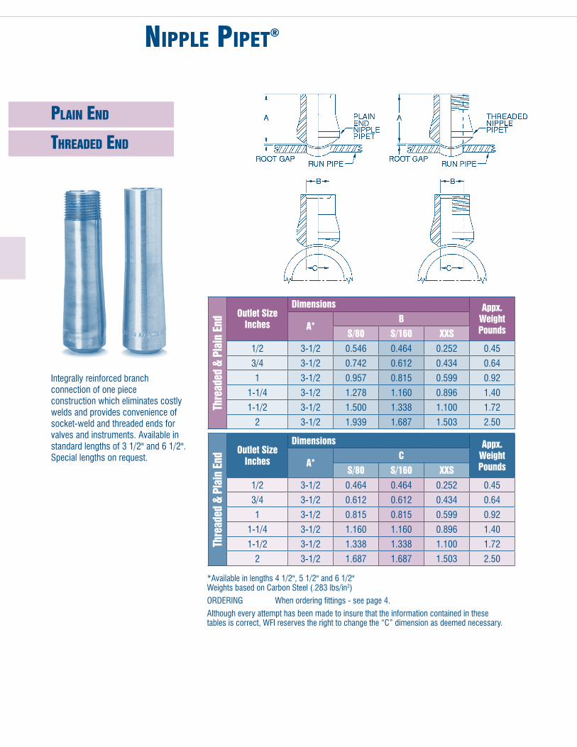
EnginEEring SpEcificationS
Lightweight ScheduLe 10S, Lw, and cLaSS 300 - StainLeSS PiPet conSoLidation chart
How It works
each outlet size indicated on the chart is designed to fit a number of run Pipe sizes, e.g., the 1/2" fitting marked 36 - 1 1/4" x 1/2" will fit all run Pipe sizes from 1 1/4" to 36". When placed on a 36" run Pipe, there will be a maximum radial gap of 1/16" between the top of the run Pipe and the base of the fitting at the crotch as shown on the sketch. this gap is negligible when welding.
tHe PIPet Means reduced Inventory
the chart above outlines the full range of thP, SWP and BWP size consolidation. this chart has been devised and the fitting designed to substantially minimize warehouse inventory. all fittings are manufactured and marked as shown on the chart.
Outlet Size Inches1/2 3/4 1 1 1/2 2 3 4
Butt-Weld Pipet, LW or CL300 and Sch. 10S1 1/4 - 1/2 36 - 1 1/2
2 1/2 - 1 36 - 3
1 1/2 - 1 4 - 2 36 - 5
2 3 - 2 1/2 10 - 3 1/2 36 - 12
3 - 2 1/2 5 - 3 1/2 18 - 6 36 - 20
3 1/2 4 5 8 - 6 14 - 10 42 - 16
5 6 10 - 8 18 - 12 44 - 20 72 - 46
Butt-Weld Pipet, CL300 x STd.1 -1/2 36 - 1 1/4
2 - 3/4 36 - 2 1/2
3 1/2 - 1 1/4 36 - 4
3 - 2 8 - 3 1/2 36 - 10
3 - 2 1/2 6 - 3 1/2 16 - 8 36 - 18
4 - 3 1/2 6 - 5 14 - 8 36 - 16
5 6 10 - 8 20 - 12 36 - 22
Socket Weld Pipet, LW or CL300 x CL 3000, and 10S x CL30001 -1/2 36 - 1 1/4
2 - 3/4 36 - 2 1/2
3 1/2 - 1 1/4 36 - 4
3 - 2 8 - 3 1/2 36 - 10
3 - 2 1/2 6 - 3 1/2 16 - 8 36 - 18
4 - 3 1/2 6 - 5 14 - 8 36 - 16
5 6 10 - 8 18 - 12 44 - 20 72 - 46
Threaded Pipet, LW or CL300 x CL 3000, and 10S x CL30001 1/2 - 3/4 36 - 2
2 1/2 - 1 36 - 3
1 1/4 - 1 4 - 1 1/2 36 - 5
2 3 1/2 - 2 1/2 10 - 4 36 - 12
2 1/2 4 - 3 10 - 5 18 - 12 36 -20
3 1/2 4 6 - 5 12 - 8 36 - 14
4 5 6 10 - 8 18 - 12 36 - 20


![[Cc Korea]License Usages In Korea](https://img.dokumen.tips/doc/110x75/5554f617b4c90566278b5408/cc-korealicense-usages-in-korea.jpg)