Embed Size (px)
Citation preview
Seismic Suspension System SolutionsTechnical Guide
CertainTeed Ceilings | Acoustic Ceilings & Suspension Systems

PURPOSE OF SEISMIC INSTALLATION REQUIREMENTS FOR SUSPENDED CEILINGS
• Provide a suspension system strong enough to resist lateral forces imposed upon it without failing
• Prevent panels from falling during a seismic event
• Limit structural damage to ceiling grid during a seismic event
• Provide life safety to building occupants during seismic events
ADOPTION OF THE INTERNATIONAL BUILDING CODE
Currently all 50 states as well as Washington, D.C., Guam, Northern Marianas Territories, Puerto Rico, the Virgin Islands, and all Federal Agencies use the International Building Code (IBC).
CODE ENFORCEMENT
The building code presents minimum design/performance requirements and in some instances prescriptive guidance. The code also sets forth limitations and conditions of use. It is important to know that while the building code establishes the requirements, the code official has the power to enforce its provisions. The code official also has the latitude to allow materials and methods of construction that are not addressed in the code. As with all code issues, the local authority having jurisdiction (AHJ) is the final arbiter for application of the IBC at that location.
CTSPC-2
Technical Support | 1-800-233-8990 | www.certainteed.com/ceilings

HOW SEISMIC DESIGN CATEGORIES ARE DETERMINED
The seismic design category A-F must be specified by a professional engineer or registered architect on the project drawings. The project requirements, which include the seismic design category, can be found in Section 1 of the specification and on the first page of the structural drawings. Jurisdictions using the 2009 IBC follow ASCE 7-05, Section 13.5.6 and the appropriate CISCA recommendations/guidelines. International Building Code allows two paths to determine Seismic Design category — IBC Section 1613 or ASCE 7 Section 11.6. The IBC states that a Seismic Design Category must be established for each construction project based on:
• Anticipated ground motion
• Soil type in a specified geographic area
• Occupancy category
These factors are used to evaluate and establish a Seismic Design Category of A, B, C, D, E or F. The installation of ceilings can be divided into three tiers of increasing requirements:
• Categories A & B are installed to meet requirements established in ASTM C636. There are no additional seismic requirements.
• Category C projects must follow ASTM C636 and ASTM E580 (CISCA Recommendations for zones 0-2 can be used if 2009 IBC governs)
• Categories D, E & F must follow ASTM C636, ASCE 7 Section 13.5.6 and ASTM E580 (CISCA Guidelines for zones 3-4 can be used if 2009 IBC governs)
Jurisdictions using the 2012 and 2015 IBC follow ASCE 7-10, Section 13.5.6 and ASTM E580 (which has replaced the CISCA documents).
p3 Technical Support | 1-800-233-8990 | www.certainteed.com/ceilings

IBC CONVENTIONAL SEISMIC INSTALLATION REQUIREMENTS SUMMARY
Technical Support | 1-800-233-8990 | www.certainteed.com/ceilings
SEISMIC DESIGN CATEGORY
Category C per 2009 IBC
Categories D, E, F per 2009 IBC
Category C per 2012 & 2015 IBC
Categories D,E,F per 2012 & 2015 IBC
REFERENCES
Corresponding American Society of Civil Engineers
(ASCE) Reference StandardASCE 7-05 ASCE 7-05 ASCE 7-10 ASCE 7-10
Corresponding CISCA or ASTM Reference Standard CISCA Zones 0-21 CISCA Zones 3-42 ASTM E 580 ASTM E 580
LIMITATIONS Weight Limitations 2.5 psf 4 psf 2.5 psf 4 psf
EXEMPTIONS
Ceiling areas less than 144 ft2 Exempt Exempt Exempt Exempt
Plaster and lath ceilings Exempt Exempt Not exempt, detailsmust be specified
Not exempt, detailsmust be specified
Drywall ceilings (screw-attached) Exempt Exempt Exempt Exempt
BASIC INSTALLATIONREQUIREMENT
Minimum strength of vertical wire connection device to the structure
Not required 100 lbs. Not required 90 lbs.
Vertical hanger wire 12-gauge @ 4’ o.c. Required Required Required Required
1 in 6 max plumb of verticalhanger wires Required Required Required Required
Rigid bracing for ceiling plane elevation changes Not required Required Not required Required
Partition attachmentAllowed only if ceiling
is allowed to move laterally
Bracing independent of ceiling splay bracing
Allowed only if ceiling is allowed to move
laterally
Bracing independent of ceiling splay bracing
GRIDREQUIREMENTS
Main runner classifications3 Intermediate or Heavy Duty Heavy Duty Intermediate or
Heavy Duty Heavy Duty
Minimum main runner and cross tee connection
strength60 lbs. 180 lbs. 60 lbs. 180 lbs.
PERIMETERREQUIREMENTS
Perimeter vertical hanger wires not more than 8"
from wall
Not required unless angle is less than 7/8" Required Not required unless
angle is less than 7/8" Required
Grid end/wall detailsMinimum 3/8"
clearance on all 4 walls
Two adjacent walls must be tight and two
adjacent walls must have a minimum 3/4" clearance
Minimum 3/8" clearance on all 4 walls
Two adjacent walls must be tight and two
adjacent walls must have a minimum 3/4" clearance
Perimeter closure (angle trim) width
Minimum 7/8"(or use perimeter wires) Minimum 2" Minimum 7/8" (or use
perimeter wires) Minimum 2"
Perimeter tees ends prevented from spreading
(Stabilizer Bars)Required Required Required Required
LATERAL BRACINGREQUIREMENTS
Horizontal restraint (splay wires or rigid bracing) within
2" of intersection and splayed 90° apart at 45° an-
gles (areas over 1,000 ft2)
Not required Required Not required Required
Compression posts (struts) 12' o.c. in both directions,
starting 6' from wallsNot required Required Not required Required
Splay bracing connection strength Not required Required
(200 lbs.) Not required Required(250 lbs.)
Seismic separation joint Not required
Required for areas larger than 2,500 ft2
(or full height partition).
Not required
Required for areas larger than 2,500 ft2 (or
full height partition). The ratio of the length to width must be less than or equal to 4:1

p5
IBC CONVENTIONAL SEISMIC INSTALLATION REQUIREMENTS SUMMARY
Technical Support | 1-800-233-8990 | www.certainteed.com/ceilings
SEISMIC DESIGN CATEGORY
Category C per 2009 IBC
Categories D, E, F per 2009 IBC
Category C per 2012 & 2015 IBC
Categories D, E, F per 2012 & 2015 IBC
LIGHT FIXTURE ATTACHMENT
Light fixture (all types) mechanically attached
to grid is required per NEC 410-16
(two per fixture unless independently
supported)
Required Required Required Required
Surface-mounted fixtures attached to grid Not required
Must be attached to ceiling with positive
clamping devices that are connected to the structure or vertical
hanger wires
Must be attached to ceiling with positive
clamping devices that are connected to the structure or vertical
hanger wires
Must be attached to ceiling with positive
clamping devices that are connected to the structure or vertical
hanger wires
Pendant-hung fixtures directly supported from structure with 9-gauge
wire (or approved alternate)
Not required Required Required Required
Rigid lay-in or can light fixtures
< 10 lbs. - one wire to structure (may be slack) Required Required Required Required
10 to 56 lbs. - two wires from fixture to structure
(may be slack)Required Required Required Required
> 56 lbs. - supported directly to structure by
approved hangersRequired Required Required Required
Rigid conduit attached to light fixtures Forbidden Permitted Forbidden Permitted
SERVICES WITHIN THE CEILING
Air Terminals
< 20 lbs. - positively attached to grid Not required Required Required Required
20 to 56 lbs. - positively attached to grid and two
12-gauge wires to structure (may be slack)
Not required Required Required Required
> 56 lbs. - directly supported to the
structureNot required Required Required Required
Sprinkler heads and otherpenetration clearance
Minimum 3/8" on all sides
Minimum 2" diameter opening or a swing joint
Minimum 3/8" on all sides
Minimum 2" diameter opening or flexible
sprinkler hose fitting
Cable trays and electrical conduit independently supported and braced
Not required Not required Not required Required
NOTES:1. Recommendations for Direct-Hung Acoustical Tile and Lay-In Panel Ceilings - CISCA 20042. Guidelines for Seismic Restraint for Direct Hung Suspended Ceilings - CISCA 20043. Per ASTM C635
Consult your local authority having jurisdiction for information specific to your region.Note that some installations do not fall under the jurisdiction of the IBC in many states, such as schools and hospitals.
Technical Support | 1-800-233-8990 | www.certainteed.com/ceilings
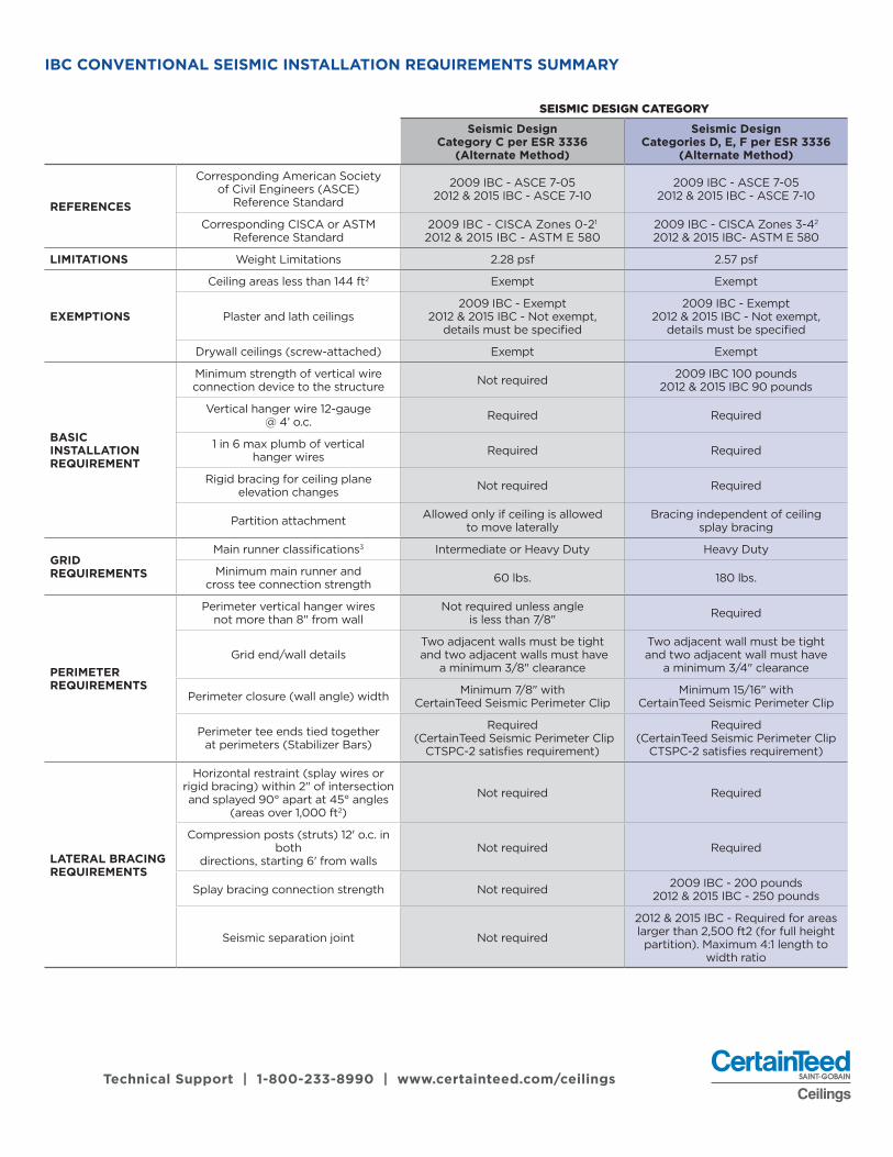
IBC CONVENTIONAL SEISMIC INSTALLATION REQUIREMENTS SUMMARY
SEISMIC DESIGN CATEGORY
Seismic DesignCategory C per ESR 3336
(Alternate Method)
Seismic DesignCategories D, E, F per ESR 3336
(Alternate Method)
REFERENCES
Corresponding American Society of Civil Engineers (ASCE)
Reference Standard
2009 IBC - ASCE 7-05 2012 & 2015 IBC - ASCE 7-10
2009 IBC - ASCE 7-05 2012 & 2015 IBC - ASCE 7-10
Corresponding CISCA or ASTMReference Standard
2009 IBC - CISCA Zones 0-21 2012 & 2015 IBC - ASTM E 580
2009 IBC - CISCA Zones 3-42 2012 & 2015 IBC- ASTM E 580
LIMITATIONS Weight Limitations 2.28 psf 2.57 psf
EXEMPTIONS
Ceiling areas less than 144 ft2 Exempt Exempt
Plaster and lath ceilings2009 IBC - Exempt
2012 & 2015 IBC - Not exempt, details must be specified
2009 IBC - Exempt 2012 & 2015 IBC - Not exempt,
details must be specified
Drywall ceilings (screw-attached) Exempt Exempt
BASIC INSTALLATIONREQUIREMENT
Minimum strength of vertical wire connection device to the structure Not required 2009 IBC 100 pounds
2012 & 2015 IBC 90 pounds
Vertical hanger wire 12-gauge@ 4’ o.c. Required Required
1 in 6 max plumb of verticalhanger wires Required Required
Rigid bracing for ceiling planeelevation changes Not required Required
Partition attachment Allowed only if ceiling is allowed to move laterally
Bracing independent of ceiling splay bracing
GRIDREQUIREMENTS
Main runner classifications3 Intermediate or Heavy Duty Heavy Duty
Minimum main runner and cross tee connection strength 60 lbs. 180 lbs.
PERIMETERREQUIREMENTS
Perimeter vertical hanger wires not more than 8" from wall
Not required unless angle is less than 7/8" Required
Grid end/wall detailsTwo adjacent walls must be tight
and two adjacent walls must have a minimum 3/8" clearance
Two adjacent wall must be tight and two adjacent wall must have
a minimum 3/4" clearance
Perimeter closure (wall angle) width Minimum 7/8" withCertainTeed Seismic Perimeter Clip
Minimum 15/16" withCertainTeed Seismic Perimeter Clip
Perimeter tee ends tied together at perimeters (Stabilizer Bars)
Required (CertainTeed Seismic Perimeter Clip
CTSPC-2 satisfies requirement)
Required (CertainTeed Seismic Perimeter Clip
CTSPC-2 satisfies requirement)
LATERAL BRACINGREQUIREMENTS
Horizontal restraint (splay wires or rigid bracing) within 2" of intersection and splayed 90° apart at 45° angles
(areas over 1,000 ft2)
Not required Required
Compression posts (struts) 12' o.c. in both
directions, starting 6' from wallsNot required Required
Splay bracing connection strength Not required 2009 IBC - 200 pounds 2012 & 2015 IBC - 250 pounds
Seismic separation joint Not required
2012 & 2015 IBC - Required for areas larger than 2,500 ft2 (for full height partition). Maximum 4:1 length to
width ratio

p7 Technical Support | 1-800-233-8990 | www.certainteed.com/ceilings
IBC CONVENTIONAL SEISMIC INSTALLATION REQUIREMENTS SUMMARY
SEISMIC DESIGN CATEGORY
Seismic DesignCategory C per ESR 3336
(Alternate Method)
Seismic DesignCategories D, E, F per ESR 3336
(Alternate Method)
LIGHT FIXTURE ATTACHMENT
Light fixture (all types) mechanically attached to grid is required
per NEC 410-16 (two per fixture unless independently supported)
Required Required
Surface-mounted fixtures attached to grid
2012 & 2015 IBC - Must be attached to ceiling with positive clamping
devices that are connected to the structure or vertical hanger wires
2012 & 2015 IBC - Must be attached to ceiling with positive clamping
devices that are connected to the structure or vertical hanger wires
Pendant-hung fixtures directlysupported from structure with
9-gauge wire (or approved alternate)Not required Required
Rigid lay-in or can light fixtures
< 10 lbs. - one wire to structure (may be slack) Required Required
10 to 56 lbs. - two wires from fixture to structure (may be slack) Required Required
> 56 lbs. - supported directly to structure by approved hangers Required Required
Rigid conduit attached to light fixtures Forbidden Permitted
SERVICES WITHIN THE CEILING
Air Terminals
< 20 lbs. - positively attached to grid Not required Required
20 to 56 lbs. - positively attached to grid and two 12-gauge wires to structure
(may be slack)Not required Required
> 56 lbs. - directly supported to the structure Not required Required
Sprinkler heads and other penetration clearance Minimum 3/8" on all sides
2009 IBC - Minimum 2" diameter or swing joint 2012 & 2015 IBC -
Minimum 2" diameter opening or flexible sprinkler hose fitting
Cable trays and electrical conduit independently supported and braced Not required Not required
NOTES:1. Recommendations for Direct-Hung Acoustical Tile and Lay-In Panel Ceilings - CISCA 20042. Guidelines for Seismic Restraint for Direct Hung Suspended Ceilings - CISCA 20043. Per ASTM C635
Consult your local authority having jurisdiction for information specific to your region.Note that some installations do not fall under the jurisdiction of the IBC in many states, such as schools and hospitals.

Technical Support | 1-800-233-8990 | www.certainteed.com/ceilings
ADDITIONAL RESOURCES ON SEISMIC CODES AND REQUIREMENTS
Contact CertainTeed Ceilings Technical Services• Phone: 1-800-233-8990
Visit these code related websites:American Society for Testing and Materials (ASTM): www.astm.org
• National Institute of Building Sciences: www.nibs.org
• International Code Council: www.icc-es.org
• U.S. Geological Survey: www.usgs.gov
• Ceilings Interior Systems Construction Association (CISCA): www.CISCA.org
• American Society of Civil Engineers (ASCE): www.ASCE.org
• City of Los Angeles Department of Building and Safety:http://netinfo.ladbs.org/rreports.nsf (RR 25978)
CERTAINTEED’S SEISMIC SUSPENSION SYSTEMS (ESR-3336)
International Code Council (ICC-ES) recognizes CertainTeed’s Seismic Suspension Systems as a code-compliant solution (ESR-3336). This evaluation and confirmation by ICC-ES provides evidence supporting the CertainTeed Suspension System and Perimeter Clip System as a code-compliant alternative to IBC requirements. CertainTeed’s ICC-ES evaluation allows the utilization of 15/16" wall angle for ceiling installations in IBC Categories D, E, and F when used with the CertainTeed Perimeter Clip (CTSPC-2). 0The ICC-ES allows you to meet seismic code requirements without the risk of delaying your construction schedule and eliminating the need for the conventional IBC installation components (2" wall angle and stabilizer bars). CertainTeed’s ICC-ES evaluation also allows the use of two fixed walls instead of a floating ceiling when used with the CertainTeed Perimeter Clip for Category C.
CATEGORIES A-F: CERTAINTEED SEISMIC SUSPENSION SYSTEMS
Product Categories CategoriesA-B
CategoryC
Categories D-F ESR-3336
15/16" Classic Stab x x x x
15/16" Classic Aluminum Capped Stab x x x x
15/16" Classic Environmental Stab x x x x
9/16" Elite Narrow Stab x x x x
9/16" EZ Stab Bolt Slot (1/8" & 1/4") x x x x
9/16" EZ Stab Tier Drop x x x x
p9 Technical Support | 1-800-233-8990 | www.certainteed.com/ceilings
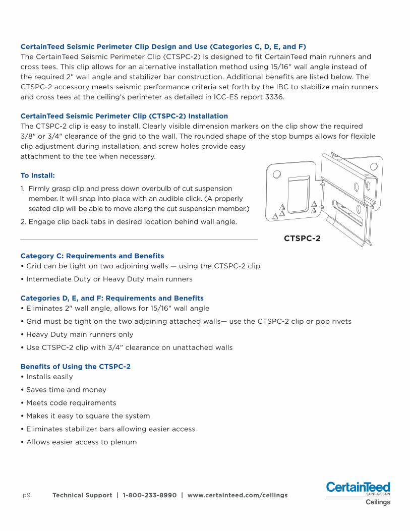
CertainTeed Seismic Perimeter Clip Design and Use (Categories C, D, E, and F) The CertainTeed Seismic Perimeter Clip (CTSPC-2) is designed to fit CertainTeed main runners and cross tees. This clip allows for an alternative installation method using 15/16" wall angle instead of the required 2" wall angle and stabilizer bar construction. Additional benefits are listed below. The CTSPC-2 accessory meets seismic performance criteria set forth by the IBC to stabilize main runners and cross tees at the ceiling’s perimeter as detailed in ICC-ES report 3336.
CertainTeed Seismic Perimeter Clip (CTSPC-2) InstallationThe CTSPC-2 clip is easy to install. Clearly visible dimension markers on the clip show the required 3/8" or 3/4" clearance of the grid to the wall. The rounded shape of the stop bumps allows for flexible clip adjustment during installation, and screw holes provide easy attachment to the tee when necessary.
To Install:
1. Firmly grasp clip and press down overbulb of cut suspension member. It will snap into place with an audible click. (A properly seated clip will be able to move along the cut suspension member.)
2. Engage clip back tabs in desired location behind wall angle.
Category C: Requirements and Benefits • Grid can be tight on two adjoining walls — using the CTSPC-2 clip
• Intermediate Duty or Heavy Duty main runners
Categories D, E, and F: Requirements and Benefits • Eliminates 2" wall angle, allows for 15/16" wall angle
• Grid must be tight on the two adjoining attached walls— use the CTSPC-2 clip or pop rivets
• Heavy Duty main runners only
• Use CTSPC-2 clip with 3/4" clearance on unattached walls
Benefits of Using the CTSPC-2 • Installs easily
• Saves time and money
• Meets code requirements
• Makes it easy to square the system
• Eliminates stabilizer bars allowing easier access
• Allows easier access to plenum
CTSPC-2
Technical Support | 1-800-233-8990 | www.certainteed.com/ceilings
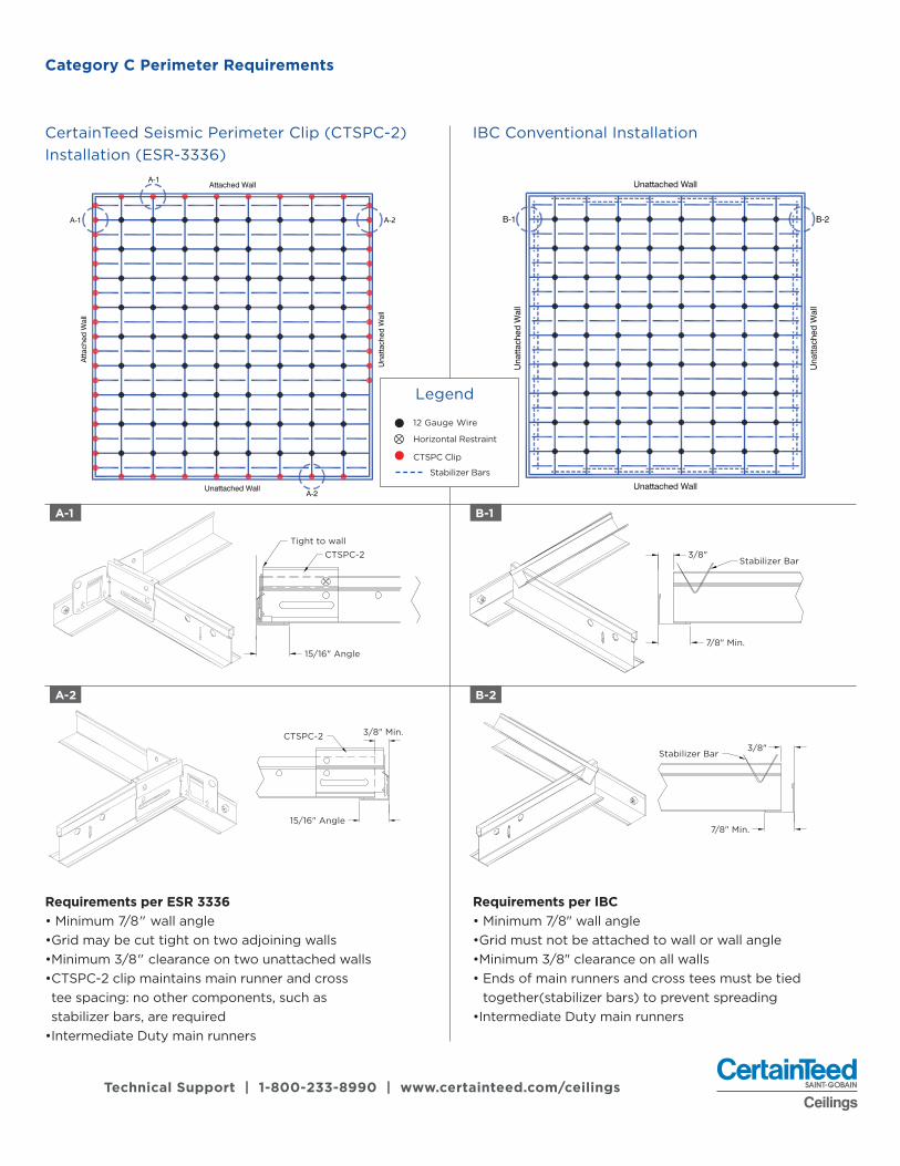
Category C Perimeter Requirements
CertainTeed Seismic Perimeter Clip (CTSPC-2) Installation (ESR-3336)
IBC Conventional Installation
Legend
12 Gauge Wire
Horizontal Restraint
CTSPC Clip
Stabilizer Bars
A-1
A-2
B-1
B-2
Tight to wallCTSPC-2
15/16" Angle7/8" Min.
Stabilizer Bar3/8"
CTSPC-2
15/16" Angle
3/8" Min.
3/8"Stabilizer Bar
7/8" Min.
Requirements per ESR 3336• Minimum 7/8" wall angle•Grid may be cut tight on two adjoining walls•Minimum 3/8" clearance on two unattached walls• CTSPC-2 clip maintains main runner and cross tee spacing: no other components, such as stabilizer bars, are required
•Intermediate Duty main runners
Requirements per IBC• Minimum 7/8" wall angle•Grid must not be attached to wall or wall angle•Minimum 3/8" clearance on all walls• Ends of main runners and cross tees must be tied
together(stabilizer bars) to prevent spreading•Intermediate Duty main runners
p11
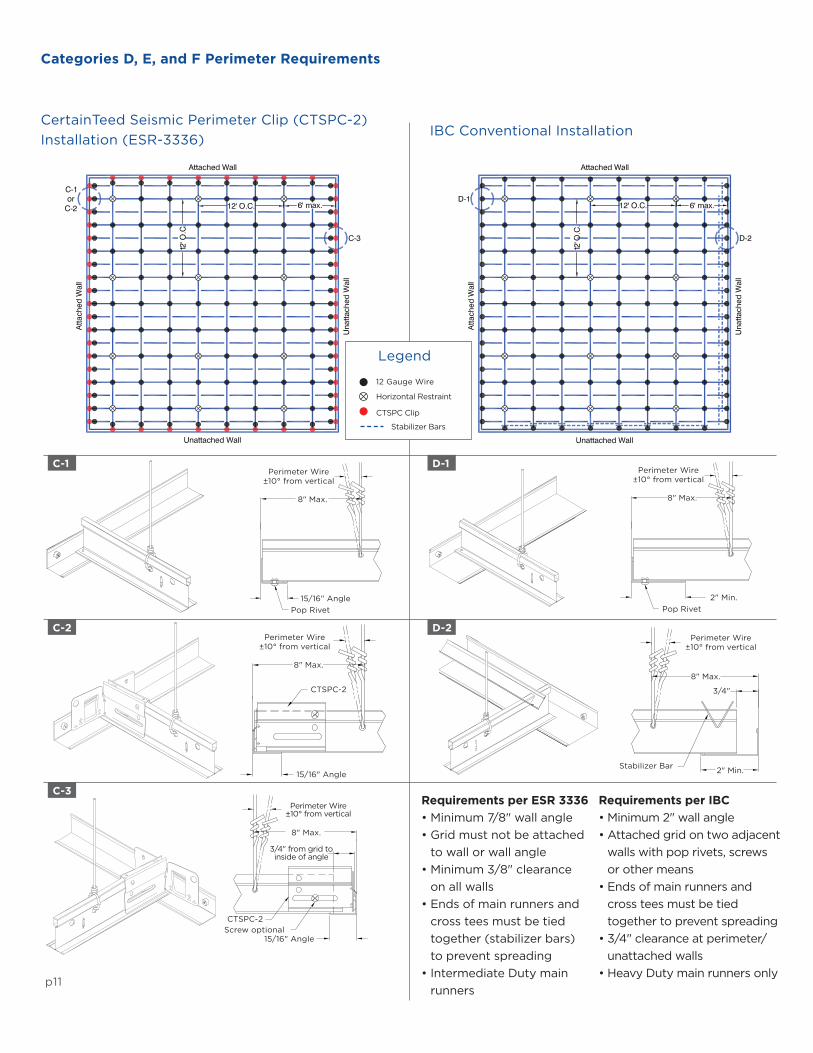
Categories D, E, and F Perimeter Requirements
IBC Conventional Installation
Legend
12 Gauge Wire
Horizontal Restraint
CTSPC Clip
Stabilizer Bars
C-1
C-2
C-3
D-1
D-2
Perimeter Wire ±10° from vertical
8" Max.
15/16" AnglePop Rivet
Requirements per ESR 3336• Minimum 7/8" wall angle• Grid must not be attached
to wall or wall angle• Minimum 3/8" clearance
on all walls• Ends of main runners and
cross tees must be tied together (stabilizer bars) to prevent spreading
• Intermediate Duty main runners
Requirements per IBC • Minimum 2" wall angle• Attached grid on two adjacent
walls with pop rivets, screws or other means
• Ends of main runners and cross tees must be tied together to prevent spreading
• 3/4" clearance at perimeter/unattached walls
• Heavy Duty main runners only
Perimeter Wire ±10° from vertical
8" Max.
2" Min.Pop Rivet
Perimeter Wire ±10° from vertical
8" Max.
CTSPC-2
15/16" Angle
Perimeter Wire ±10° from vertical
8" Max.
Stabilizer Bar 2" Min.
3/4"
15/16" AngleScrew optionalCTSPC-2
8" Max.
3/4" from grid to inside of angle
Perimeter Wire ±10° from vertical
CertainTeed Seismic Perimeter Clip (CTSPC-2) Installation (ESR-3336)

Technical Support | 1-800-233-8990 | www.certainteed.com/ceilings
ADDITIONAL RESOURCES ON SEISMIC CODES AND REQUIREMENTS
Seismic Separation Joint Requirements (Categories D, E, and F)Seismic separation joints are prescribed for seismic design categories D, E and F by the International Building Code (IBC) through reference to ASCE 7 mandates that ceiling areas exceeding 2,500 ft2 (232m2), must have seismic separation joints or full height partitions that divide the ceiling into areas not exceeding 2,500 ft2. The length to width ratios in these areas must not be greater than 4:1.
CertainTeed Seismic Transition Joint Clip (CTSTJ)Benefits
• Aesthetically masks presence of separation joint
• Saves time with a reliable installation method
• Non-directional and can be used on either main tees or cross tees
• Allows for full acoustical panel at the joint
• Easier to keep the ceiling system square
• Eliminates the need for additional hanger wires
• Has clip placement (over the bulb of the tee) that does not interfere with typical light fixtures)
Construction (Cross Tee Separation Joint)
Seismic Separation Joint ZoneCross Tee Separation JointMain Runner Separation Joint4-way Separation Joint
Main RunnerCross Tee Fastener CTSTJ
Cut or Remove Cross Tee Clips

p13 Technical Support | 1-800-233-8990 | www.certainteed.com/ceilings
Construction (Main Runner Separation Joint)
Construction (Main Runner Separation Joint)
Seismic Separation Joint ZoneCross Tee Separation JointMain Runner Separation Joint4-way Separation Joint
Seismic Separation Joint ZoneCross Tee Separation JointMain Runner Separation Joint4-way Separation Joint
Fields Cut Main Runner 3/4" Min. Type
One Side of Sleeve Crimped to Allow Movement Only on Opposite End
FastenerCTSTJCross Tee Main Runner
Main Runner
CTSTJ
Fastener
Cross Tee
One Side of Sleeve Crimped to Allow Movement Only on Opposite End
3/4" Gap Between Field Cut Main Runner Sleeve
Fastener
CTSTJ
OPTION 1
OPTION 2
Cross Tee Main Runner
3/4" Gap Between Field Cut Main Runner Sleeve
One Side of Sleeve Crimped to Allow Movement Only on Opposite End
Cross Tee Main Runner
3/4" Gap Between Field
Cut Main Runner Sleeve
CTSTJFastener

Technical Support | 1-800-233-8990 | www.certainteed.com/ceilings
Bracing and Restraint for Seismic InstallationsTypical seismic bracing for wall-to-wall ceilings consists of individual clusters of four, 12-gauge wires arrayed 90˚ from one another and attached to the main runner within 2" of a cross tee intersection. The wires are to be angled no more than 45˚ from the plane of the ceiling. The compression post is attached to the grid at the cluster of wires and extends to the overhead structure.
The compression post should be engineered for the application and the longer its length, the more substantial it must be. Typical post material can be made of EMT conduit or steel stud (see Horizontal Restraint below).
Note: Information regarding maximum lengths of vertical compression posts is available upon request.
The code also allows for the use of rigid bracing. When a rigid member is used in place of wires it can handle loads in two directions (push and/or pull), so only two lateral bracing members at 90˚ to each other are required.
The exemption from lateral force bracing for ceilings less than or equal to 1,000 ft2 (93 m2) should not be confused with the exemption for ceilings less than or equal to 144 ft2
(13.4 m2). The 144 ft2 (13.4 m2) exemption is a blanket exemption from all seismic force requirements (2-inch wall angle, heavy duty main runners, lateral force bracing wires compression posts, etc.). The 1,000 ft2 exemption is only for lateral bracing.
The lateral force bracing consists of both the splay wires and the compression post. Exempting lateral bracing exempts both the splay wires and the compression post. The lateral force bracing must start within 6 feet of two adjacent walls. It is not necessary to end the lateral force bracing within 6 feet of the opposite two walls. The last lateral force brace must only be within 12 feet of the opposite walls.
It is not necessary to run the lateral force bracing wires parallel to the grid layout in plan view. They can be at any arbitrary angle. It is also not necessary that all the lateral force braces have the same orientation. Lateral force bracing should be taut to function correctly.
Island (Clouds) or Sloped Ceiling Seismic ApplicationsFor Island or Sloped Applications, please reference the CISCA Seismic Construction Handbook and local authority having jurisdiction.
Horizontal Restraint
Main RunnerCross Tee
Compression Post
12 GA. Hanger Wire

Technical Support | 1-800-233-8990 | www.certainteed.com/ceilingsp15
Seismic Grid Accessories Ease Installation • Easily integrates with multiple grid profiles
• Two-sided design of CTSPC -2 allows for implementation near any corner
• The CTSTJ clip simplifies installation of single clip in certain seismic applications.
• For more information on CertainTeed Ceilings accessories and add this link: https://www.certainteed.com/resources/CTC_Grid_Installation_Accessories_DataPage.pdf.
Seismic Grid Accessories
Item # Description Packaging
SLEEVE 1516 15/16” Sleeve 100 per carton
SLEEVE 916 9/16” Sleeve 100 per carton
CTSPC-2 Seismic Perimeter Clip 100 per carton
CTSTJ Seismic Transition Joint Clip 100 per carton
CTSPC-2
SLEEVE 1516 SLEEVE 916
CTSTJ

© 02/18 CertainTeed. Printed in U.S.A. CTC-06-301
CertainTeed Ceilings | Acoustic Ceilings & Suspension Systems20 Moores Road Malvern, PA 19355 Professional: 800-233-8990 Consumer: 800-782-8777 certainteed.com/ceilings


![[ International Code ] Seismic Design Manual - IBC 2009 Vol 2](https://img.dokumen.tips/doc/110x75/55cf979d550346d033929502/-international-code-seismic-design-manual-ibc-2009-vol-2.jpg)


![[ International Code ] Seismic Design Manual - IBC 2012 Vol 1](https://img.dokumen.tips/doc/110x75/55cf979d550346d033929509/-international-code-seismic-design-manual-ibc-2012-vol-1.jpg)


![[ International Code ] Seismic Design Manual - IBC 2012 Vol 2](https://img.dokumen.tips/doc/110x75/55cf979d550346d03392950e/-international-code-seismic-design-manual-ibc-2012-vol-2.jpg)