Embed Size (px)
Citation preview

2012 SEATTLE EXISTING BUILDING CODE 85
Appendix A: Guidelines for the Seismic Retrofit of Existing Buildings
CHAPTER A1
SEISMIC STRENGTHENING PROVISIONS FOR UNREINFORCED MASONRY BEARING WALL BUILDINGS
SECTION A101PURPOSE
[B] A101.1 Purpose. The purpose of this chapter is to pro-mote public safety and welfare by reducing the risk of deathor injury that may result from the effects of earthquakes onexisting unreinforced masonry bearing wall buildings.
The provisions of this chapter are intended as minimumstandards for structural seismic resistance, and are establishedprimarily to reduce the risk of life loss or injury. Compliancewith these provisions will not necessarily prevent loss of lifeor injury, or prevent earthquake damage to rehabilitatedbuildings.
SECTION A102SCOPE
[B] A102.1 General. The provisions of this chapter shallapply to all existing buildings having at least one unrein-forced masonry bearing wall. The elements regulated by thischapter shall be determined in accordance with Table A1-A.Except as provided herein, other structural provisions of thebuilding code shall apply. This chapter does not apply to thealteration of existing electrical, plumbing, mechanical or firesafety systems.
[B] A102.2 Essential and hazardous facilities. The provi-sions of this chapter shall not apply to the strengthening ofbuildings in Risk Categories III or IV. Such buildings shallbe strengthened to meet the requirements of the InternationalBuilding Code for new buildings of the same risk category orother such criteria approved by the code official.
SECTION A103DEFINITIONS
For the purpose of this chapter, the applicable definitions inthe building code shall also apply.
[B] COLLAR JOINT. The vertical space between adjacentwythes. A collar joint may contain mortar or grout.
[B] CROSSWALL. A new or existing wall that meets therequirements of Section A111.3 and the definition of SectionA111.3. A crosswall is not a shear wall.
[B] CROSSWALL SHEAR CAPACITY. The unit shearvalue times the length of the crosswall, νcLc.
[B] DIAPHRAGM EDGE. The intersection of the horizon-tal diaphragm and a shear wall.
[B] DIAPHRAGM SHEAR CAPACITY. The unit shearvalue times the depth of the diaphragm, νuD.
[B] FLEXIBLE DIAPHRAGM. A diaphragm of wood oruntopped metal deck construction.
[B] NORMAL WALL. A wall perpendicular to the directionof seismic forces.
[B] OPEN FRONT. An exterior building wall line withoutvertical elements of the lateral force-resisting system in oneor more stories.
[B] POINTING. ((The partial reconstruction of the bedjoints of an unreinforced masonry wall as defined in UBCStandard 21-8.)) The process of removal of deteriorated mor-tar from between masonry units and placement of new mor-tar. Also known as repointing or tuckpointing for purposes ofthis chapter.
REPOINTING. See Pointing.
[B] RIGID DIAPHRAGM. A diaphragm of concrete con-struction.
TUCKPOINTING. See Pointing.
[B] UNREINFORCED MASONRY. Includes burned clay,concrete or sand-lime brick; hollow clay or concrete block;plain concrete; and hollow clay tile. These materials shallcomply with the requirements of Section A106 as applicable.
[B] UNREINFORCED MASONRY BEARING WALL. AURM wall that provides the vertical support for the reactionof floor or roof-framing members.
[B] UNREINFORCED MASONRY (URM) WALL. Amasonry wall that relies on the tensile strength of masonryunits, mortar and grout in resisting design loads, and in whichthe area of reinforcement is less than 25 percent of the mini-mum ratio required by the building code for reinforcedmasonry.
[B] YIELD STORY DRIFT. The lateral displacement ofone level relative to the level above or below at which yieldstress is first developed in a frame member.
SECTION A104SYMBOLS AND NOTATIONS
For the purpose of this chapter, the following notations sup-plement the applicable symbols and notations in the buildingcode.
an = Diameter of core multiplied by its length or thearea of the side of a square prism.
A = Cross-sectional area of unreinforced masonry pieror wall, square inches (10-6 m2).
Ab = Total area of the bed joints above and below thetest specimen for each in-place shear test, squareinches (10-6 m2).
�
�
17_ChA1_Seattle_Existing_12.fm Page 85 Thursday, October 31, 2013 12:36 PM

APPENDIX A
86 2012 SEATTLE EXISTING BUILDING CODE
D = In-plane width dimension of pier, inches (10-3 m),or depth of diaphragm, feet (m).
DCR = Demand-capacity ratio specified in SectionA111.4.2.
f'm = Compressive strength of masonry.
fsp = Tensile-splitting strength of masonry.
Fwx = Force applied to a wall at level x, pounds (N).
H = Least clear height of opening on either side of apier, inches (10-3 m).
h/t = Height-to-thickness ratio of URM wall. Height, h,is measured between wall anchorage levels and/orslab-on-grade.
L = Span of diaphragm between shear walls, or spanbetween shear wall and open front, feet (m).
Lc = Length of crosswall, feet (m).
Li = Effective span for an open-front building specifiedin Section A111.8, feet (m).
P = Applied force as determined by standard test methodof ASTM C 496 or ASTM E 519, pounds (N).
PD = Superimposed dead load at the location underconsideration, pounds (kN). For determination ofthe rocking shear capacity, dead load at the top ofthe pier under consideration shall be used.
PD+L = Press resulting from the dead plus actual live loadin place at the time of testing, pounds per squareinch (kPa).
Pw = Weight of wall, pounds (N).
R = Response modification factor for Ordinary plainmasonry shear walls in Bearing Wall System fromTable 12.2-1 of ASCE 7, where R = 1.5.
SDS = Design spectral acceleration at short period, in gunits.
SD1 = Design spectral acceleration at 1-second period, ing units.
va = The shear strength of any URM pier, νmA/1.5pounds (N).
vc = Unit shear capacity value for a crosswall sheathedwith any of the materials given in Table A1-D orA1-E, pounds per foot (N/m).
vm = Shear strength of unreinforced masonry, poundsper square inch (kPa).
Vaa = The shear strength of any URM pier or wall,pounds (N).
Vca = Total shear capacity of crosswalls in the directionof analysis immediately above the diaphragm levelbeing investigated, νcLc, pounds (N).
Vcb = Total shear capacity of crosswalls in the directionof analysis immediately below the diaphragm levelbeing investigated, vcLc, pounds (N).
Vp = Shear force assigned to a pier on the basis of itsrelative shear rigidity, pounds (N).
Vr = Pier rocking shear capacity of any URM wall orwall pier, pounds (N).
vt = Mortar shear strength as specified in SectionA106.3.3.5, pounds per square inch (kPa).
Vtest = Load at incipient cracking for each in-place sheartest ((per UBC Standard 21-6)) performed inaccordance with Section A106.3.3.1, pounds (kN).
vto = Mortar shear test values as specified in SectionA106.3.3.5, pounds per square inch (kPa).
vu = Unit shear capacity value for a diaphragm sheathedwith any of the materials given in Table A1-D orA1-E, pounds per foot (N/m).
Vwx = Total shear force resisted by a shear wall at thelevel under consideration, pounds (N).
W = Total seismic dead load as defined in the buildingcode, pounds (N).
Wd = Total dead load tributary to a diaphragm level,pounds (N).
Ww = Total dead load of a URM wall above the levelunder consideration or above an open-front building,pounds (N).
Wwx = Dead load of a URM wall assigned to level xhalfway above and below the level underconsideration, pounds (N).
ΣvuD = Sum of diaphragm shear capacities of both ends ofthe diaphragm, pounds (N).
ΣΣvuD = For diaphragms coupled with crosswalls, νuDincludes the sum of shear capacities of both ends ofdiaphragms coupled at and above the level underconsideration, pounds (N).
ΣWd = Total dead load of all the diaphragms at and abovethe level under consideration, pounds (N).
SECTION A105GENERAL REQUIREMENTS
[B] A105.1 General. The seismic force-resisting systemspecified in this chapter shall comply with the building code,except as modified herein.
[B] A105.2 Alterations and repairs. Alterations and repairsrequired to meet the provisions of this chapter shall complywith applicable structural requirements of the building codeunless specifically provided for in this chapter.
[B] A105.3 Requirements for plans. The following con-struction information shall be included in the plans requiredby this chapter:
1. Dimensioned floor and roof plans showing existingwalls and the size and spacing of floor and roof-fram-ing members and sheathing materials. The plans shallindicate all existing and new crosswalls and shear wallsand their materials of construction. The location ofthese walls and their openings shall be fully dimen-sioned and drawn to scale on the plans.
17_ChA1_Seattle_Existing_12.fm Page 86 Thursday, October 31, 2013 12:36 PM

APPENDIX A
2012 SEATTLE EXISTING BUILDING CODE 87
2. Dimensioned wall elevations showing openings, piers,wall classes as defined in Section A106.3.3.8, thick-ness, heights, wall shear test locations, cracks or dam-aged portions requiring repairs, the general condition ofthe mortar joints, and if and where pointing is required.Where the exterior face is veneer, the type of veneer, itsthickness and its bonding and/or ties to the structuralwall masonry shall also be noted.
3. The type of interior wall and ceiling materials, andframing.
4. The extent and type of existing wall anchorage to floorsand roof when used in the design.
5. The extent and type of parapet corrections that werepreviously performed, if any.
6. Repair details, if any, of cracked or damaged unrein-forced masonry walls required to resist forces specifiedin this chapter.
7. All other plans, sections and details necessary to delin-eate required retrofit construction.
8. The design procedure used shall be stated on both theplans and the permit application.
9. Details of the anchor prequalification program requiredby ((UBC Standard 21-7)) Section A107.5.3, if used,including location and results of all tests.
[B] A105.4 Structural observation, testing and inspection.Structural observation, in accordance with Section 1709 ofthe International Building Code, shall be required for allstructures in which seismic retrofit is being performed inaccordance with this chapter. Structural observation shallinclude visual observation of work for conformance with theapproved construction documents and confirmation of exist-ing conditions assumed during design.
Structural testing and inspection for new constructionmaterials shall be in accordance with the building code,except as modified by this chapter.
SECTION A106MATERIALS REQUIREMENTS
[B] A106.1 General. Materials permitted by this chapter,including their appropriate strength design values and thoseexisting configurations of materials specified herein, may beused to meet the requirements of this chapter.
[B] A106.2 Existing materials. Existing materials used aspart of the required vertical load-carrying or lateral force-resisting system shall be in sound condition, or shall berepaired or removed and replaced with new materials. Allother unreinforced masonry materials shall comply with thefollowing requirements:
1. The lay-up of the masonry units shall comply with Sec-tion A106.3.2, and the quality of bond between theunits has been verified to the satisfaction of the ((build-ing official)) code official;
2. Concrete masonry units are verified to be load-bearingunits complying with ((UBC Standard 21-4)) ASTM
C90 or such other standard as is acceptable to the((building official)) code official; and
3. The compressive strength of plain concrete walls shallbe determined based on cores taken from each class ofconcrete wall. The location and number of tests shall bethe same as those prescribed for tensile-splittingstrength tests in Sections A106.3.3.3 and A106.3.3.4, orin Section A108.1.
The use of materials not specified herein or in SectionA108.1 shall be based on substantiating research data or engi-neering judgment, with the approval of the ((building offi-cial)) code official.
[B] A106.3 Existing unreinforced masonry.
[B] A106.3.1 General. Unreinforced masonry walls usedto carry vertical loads or seismic forces parallel and per-pendicular to the wall plane shall be tested as specified inthis section. All masonry that does not meet the minimumstandards established by this chapter shall be removed andreplaced with new materials, or alternatively, shall have itsstructural functions replaced with new materials and shallbe anchored to supporting elements.
[B] A106.3.2 Lay-up of walls.
[B] A106.3.2.1 Multiwythe solid brick. The facing andbacking shall be bonded so that not less than 10 percentof the exposed face area is composed of solid headersextending not less than 4 inches (102 mm) into the back-ing. The clear distance between adjacent full-lengthheaders shall not exceed 24 inches (610 mm) vertically orhorizontally. Where the backing consists of two or morewythes, the headers shall extend not less than 4 inches(102 mm) into the most distant wythe, or the backingwythes shall be bonded together with separate headerswith their area and spacing conforming to the foregoing.Wythes of walls not bonded as described above shall beconsidered veneer. Veneer wythes shall not be includedin the effective thickness used in calculating the height-to-thickness ratio and the shear capacity of the wall.
Exception: Where SD1 is not more than 0.3,((Veneer)) veneer wythes anchored as specified inthe building code and made composite with backupmasonry may be used for calculation of the effectivethickness ((, where SD1 exceeds 0.3)).
[B] A106.3.2.2 Grouted or ungrouted hollow concreteor clay block and structural hollow clay tile. Groutedor ungrouted hollow concrete or clay block and structuralhollow clay tile shall be laid in a running bond pattern.
[B] A106.3.2.3 Other lay-up patterns. Lay-up pat-terns other than those specified in Sections A106.3.2.1and A106.3.2.2 above are allowed if their performancecan be justified.
[B] A106.3.3 Testing of masonry.
[B] A106.3.3.1 Mortar tests. The quality of mortar inall masonry walls shall be determined by performingin-place shear tests in accordance with the following:
1. The bed joints of the outer wythe of the masonry((should)) shall be tested in shear by laterally dis-
17_ChA1_Seattle_Existing_12.fm Page 87 Thursday, October 31, 2013 12:36 PM

APPENDIX A
88 2012 SEATTLE EXISTING BUILDING CODE
placing a single brick relative to the adjacentbricks in the same wythe. The head joint oppositethe loaded end of the test brick ((should)) shall becarefully excavated and cleared. The brick adja-cent to the loaded end of the test brick ((should))shall be carefully removed by sawing or drillingand excavating to provide space for a hydraulicram and steel loading blocks. Steel blocks, thesize of the end of the brick, ((should)) shall beused on each end of the ram to distribute the loadto the brick. The blocks ((should)) shall not con-tact the mortar joints. The load ((should)) shall beapplied horizontally, in the plane of the wythe.The load recorded at first movement of the testbrick as indicated by spalling of the face of themortar bed joints is Vtest in Equation A1-3.
2. Alternative procedures for testing shall be usedwhere in-place testing is not practical because ofcrushing or other failure mode of the masonryunit (see Section A106.3.3.2).
[B] A106.3.3.2 Alternative procedures for testingmasonry. The tensile-splitting strength of existingmasonry, fsp, or the prism strength of existing masonry,f'm, may be determined in accordance with one of thefollowing procedures:
1. Wythes of solid masonry units shall be tested bysampling the masonry by drilled cores of not lessthan 8 inches (203 mm) in diameter. A bed jointintersection with a head joint shall be in the cen-ter of the core. The tensile-splitting strength ofthese cores should be determined by the standardtest method of ASTM C 496. The core should beplaced in the test apparatus with the bed joint 45degrees from the horizontal. The tensile-splittingstrength should be determined by the followingequation:
(Equation A1-1)
2. Hollow unit masonry constructed of through-the-wall units shall be tested by sampling themasonry by a sawn square prism of not less than18 inches square (11 613 mm2). The tensile-split-ting strength should be determined by the stan-dardtest method of ASTM E 519. The diagonal ofthe prism should be placed in a vertical position.The tensile-splitting strength should be deter-mined by the following equation:
(Equation A1-2)
3. An alternative to material testing is estimation ofthe f'm of the existing masonry. This alternativeshould be limited to recently constructedmasonry. The determination of f'm requires thatthe unit correspond to a specification of the unitby an ASTM standard and classification of themortar by type.
[B] A106.3.3.3 Location of tests. The shear tests shallbe taken at locations representative of the mortar condi-tions throughout the entire building, taking into accountvariations in workmanship at different building heightlevels, variations in weathering of the exterior surfaces,and variations in the condition of the interior surfacesdue to deterioration caused by leaks and condensationof water and/or by the deleterious effects of other sub-stances contained within the building. The exact testlocations shall be determined at the building site by theengineer or architect in responsible charge of the struc-tural design work. An accurate record of all such testsand their locations in the building shall be recorded, andthese results shall be submitted to the building depart-ment for approval as part of the structural analysis.
[B] A106.3.3.4 Number of tests. The minimum num-ber of tests per class shall be as follows:
1. At each of both the first and top stories, not lessthan two tests per wall or line of wall elementsproviding a common line of resistance to lateralforces.
2. At each of all other stories, not less than one testper wall or line of wall elements providing acommon line of resistance to lateral forces.
3. In any case, not less than one test per 1,500square feet (139.4 m2) of wall surface and not lessthan a total of eight tests.
[B] A106.3.3.5 Minimum quality of mortar.
1. Mortar shear test values, νto, in pounds per squareinch (kPa) shall be obtained for each in-placeshear test in accordance with the following equa-tion:
vto = (Vtest/Ab) - PD+L (Equation A1-3)
2. Individual unreinforced masonry walls with νto
consistently less than 30 pounds per square inch(207 kPa) shall be entirely pointed prior to retest-ing.
3. The mortar shear strength, νt, is the value inpounds per square inch (kPa) that is exceeded by80 percent of the mortar shear test values, νto.
4. Unreinforced masonry with mortar shear strength,νt, less than 30 pounds per square inch (207 kPa)shall be removed, pointed and retested or shallhave its structural function replaced, and shall beanchored to supporting elements in accordancewith Sections A106.3.1 and A113.8. When exist-ing mortar in any wythe is pointed to increase itsshear strength and is retested, the condition of themortar in the adjacent bed joints of the innerwythe or wythes and the opposite outer wytheshall be examined for extent of deterioration. Theshear strength of any wall class shall be no greaterthan that of the weakest wythe of that class.
[B] A106.3.3.6 Minimum quality of masonry.
1. The minimum average value of tensile-splittingstrength determined by Equation A1-1 or A1-2
fsp2Pπan--------=
fsp0.494Pan
-----------------=
17_ChA1_Seattle_Existing_12.fm Page 88 Thursday, October 31, 2013 12:36 PM

APPENDIX A
2012 SEATTLE EXISTING BUILDING CODE 89
shall be 50 pounds per square inch (344.7 kPa).The minimum value of f'm determined by catego-rization of the masonry units and mortar shouldbe 1,000 pounds per square inch (6895 kPa).
2. Individual unreinforced masonry walls with aver-age tensile-splitting strength of less than 50pounds per square inch (344.7 kPa) shall beentirely pointed prior to retesting.
3. Hollow unit unreinforced masonry walls withestimated prism compressive strength of less than1,000 pounds per square inch (6895 kPa) shall begrouted to increase the average net area compres-sive strength.
[B] A106.3.3.7 Collar joints. The collar joints shall beinspected at the test locations during each in-placeshear test, and estimates of the percentage of adjacentwythe surfaces that are covered with mortar shall bereported along with the results of the in-place sheartests.
[B] A106.3.3.8 Unreinforced masonry classes. Exist-ing unreinforced masonry shall be categorized into oneor more classes based on shear strength, quality of con-struction, state of repair, deterioration and weathering.A class shall be characterized by the allowable masonryshear stress determined in accordance with SectionA108.2. Classes shall be defined for whole walls, notfor small areas of masonry within a wall.
[B] A106.3.3.9 Pointing. Deteriorated mortar joints inunreinforced masonry walls shall be pointed ((accord-ing to UBC Standard 21-8)) in accordance with the fol-lowing requirements.
1. Joint preparation. The deteriorated mortar shallbe cut out by means of a toothing chisel or non-impact power tool to a depth at which sound mor-tar is reached but not less than 3/4-inch (19 mm).Care shall be taken not to damage the brickedges. After cutting is complete, all loose mate-rial shall be removed with a brush, air stream, orwater stream.
2. Mortar preparation. The mortar mix shall beproportioned as required by the registered designprofessional. The pointing mortar shall be prehy-drated by first thoroughly mixing all ingredientsdry and then mixing again, adding only enoughwater to produce a damp workable mix whichwill retain its form when pressed into a ball. Themortar shall be kept in a damp condition for oneand one-half hours; then sufficient water shall beadded to bring it to a consistency that is some-what drier than conventional masonry mortar.
3. Packing. The joint into which the mortar is to bepacked shall be damp but without freestandingwater. The mortar shall be tightly packed into thejoint in layers not exceeding 1/4-inch (6.4 mm) indepth until it is filled; then it shall be tooled to asmooth surface to match the original profile.
Nothing shall prevent pointing of any deterioratedmasonry wall joints before ((the tests are made)) testingin accordance with Section A106.3.3 is performed,except as required in Section A107.1.
SECTION A107QUALITY CONTROL
[B] A107.1 Pointing. Preparation and mortar pointing shallbe performed with special inspection.
Exception: At the discretion of the building official, inci-dental pointing may be performed without special inspec-tion.
[B] A107.2 Masonry shear tests. In-place masonry sheartests shall comply with Section A106.3.3.1. Testing ofmasonry for determination of tensile-splitting strength shallcomply with Section A106.3.3.2.
[B] A107.3 Existing wall anchors. Existing wall anchorsused as all or part of the required tension anchors shall betested in pullout according to ((UBC Standard 21-7)) SectionA107.5.1. The minimum number of anchors tested shall befour per floor, with two tests at walls with joists framing intothe wall and two tests at walls with joists parallel to the wall,but not less than 10 percent of the total number of existingtension anchors at each level.
[B] A107.4 New bolts. All new embedded bolts shall be sub-ject to periodic special inspection in accordance with thebuilding code, prior to placement of the bolt and grout oradhesive in the drilled hole. Five percent of all bolts that donot extend through the wall shall be subject to a direct-ten-sion test, and an additional 20 percent shall be tested using acalibrated torque wrench. Testing shall be performed inaccordance with ((UBC Standard 21-7)) Section A107.5.1.New bolts that extend through the wall with steel plates onthe far side of the wall need not be tested.
Exception: Special inspection in accordance with thebuilding code may be provided during installation of newanchors in lieu of testing.
All new embedded bolts resisting tension forces or a combi-nation of tension and shear forces shall be subject to periodicspecial inspection in accordance with the building code, priorto placement of the bolt and grout or adhesive in the drilledhole. Five percent of all bolts resisting tension forces shall besubject to a direct-tension test, and an additional 20 percentshall be tested using a calibrated torque wrench. Testing shallbe performed in accordance with ((UBC Standard 21-7)) Sec-tion A107.5.1 New through-bolts need not be tested.
[B]A107.5 Tests of anchors in unreinforced masonrywalls.
[B]A107.5.1 Direct tension testing of existing anchorsand new bolts. The test apparatus shall be supported bythe masonry wall. The distance between the anchor andthe test apparatus support shall not be less than one-halfthe wall thickness for existing anchors and 75 percent ofthe embedment for new embedded bolts. Existing wallanchors shall be given a preload of 300 pounds (1335 N)prior to establishing a datum for recording elongation.
17_ChA1_Seattle_Existing_12.fm Page 89 Thursday, October 31, 2013 12:36 PM

APPENDIX A
90 2012 SEATTLE EXISTING BUILDING CODE
The tension test load reported shall be recorded at 1/8 inch(3.2 mm) relative movement between the existing anchorand the adjacent masonry surface. New embedded ten-sion bolts shall be subject to a direct tension load of notless than 2.5 times the design load but not less than 1,500pounds (6672 N) for five minutes (10 percent deviation).
[B]A107.5.2 Torque testing of new bolts. Bolts embed-ded in unreinforced masonry walls shall be tested using atorque-calibrated wrench to the following minimumtorques:
1/2-inch-diameter (13 mm) bolts: 40 foot pounds (54.2N-m) 5/8-inch-diameter (16 mm) bolts: 50 foot pounds (67.8N-m) 3/4-inch-diameter (19 mm) bolts: 60 foot pounds (81.3N-m)
[B]A107.5.3 Prequalification test for bolts and othertypes of anchors. This section is applicable when it isdesired to use tension or shear values for anchors greaterthan those permitted by Table A1-E. The direct-tensiontest procedure set forth in Section A107.5.1 for existinganchors shall be used to determine the allowable tensionvalues for new embedded through bolts, except that nopreload is required. Bolts shall be installed in the samemanner and using the same materials as will be used inthe actual construction. A minimum of five tests for eachbolt size and type shall be performed for each class ofmasonry in which they are proposed to be used. Theallowable tension values for such anchors shall be thelesser of the average ultimate load divided by a factor ofsafety of 5.0 or the average load at which 1/8-inch (3.2mm) elongation occurs for each size and type of bolt andclass of masonry.
The test procedure for prequalification of shear boltsshall comply with ASTM E 488 or another approved pro-cedure.
The allowable values determined in this manner shall bepermitted to exceed those set forth in Table A1- E.
[B]A107.5.4 Reports. Results of all tests shall bereported. The report shall include the test results as relatedto anchor size and type, orientation of loading, details ofthe anchor installation and embedment, wall thickness,and joist orientation.
SECTION A108DESIGN STRENGTHS
[B] A108.1 Values.
1. Strength values for existing materials are given inTable A1-D and for new materials in Table A1-E.
2. Capacity reduction factors need not be used.
3. The use of new materials not specified herein shall bebased on substantiating research data or engineeringjudgment, with the approval of the building official.
[B] A108.2 Masonry shear strength. The unreinforcedmasonry shear strength, vm, shall be determined for eachmasonry class from one of the following equations:
1. The unreinforced masonry shear strength, vm, shall bedetermined by Equation A1-4 when the mortar shearstrength has been determined by Section A106.3.3.1.
(Equation A1-4)
The mortar shear strength values, vt, shall be deter-mined in accordance with Section A106.3.3.((5 andshall not exceed 100 pounds per square inch (689.5kPa) for the determination of vm.))
2. The unreinforced masonry shear, vm, shall be deter-mined by Equation A1-5 when tensile-splitting strengthhas been determined in accordance with Section A106.3.3.2, Item 1 or 2.
(Equation A1-5)
3. When f'm has been estimated by categorization of theunits and mortar in accordance with Section 2105.2.2.1of the International Building Code, the unreinforcedmasonry shear strength, vm, shall not exceed 200pounds per square inch (1380 kPa) or the lesser of thefollowing:
a) or
b) 200 psi or
c) (Equation A1-6)
For SI: 1 psi = 6.895 kPa.
where:
v = 62.5 psi (430 kPa) for running bond masonrynot grouted solid.
v = 100 psi (690 kPa) for running bond masonrygrouted solid.
v = 25 psi (170 kPa) for stack bond grouted solid.
[B] A108.3 Masonry compression. Where any increase indead plus live compression stress occurs, the compressionstress in unreinforced masonry shall not exceed 300 poundsper square inch (2070 kPa).
[B] A108.4 Masonry tension. Unreinforced masonry shallbe assumed to have no tensile capacity.
[B] A108.5 Existing tension anchors. The resistance valuesof the existing anchors shall be the average of the tensiontests of existing anchors having the same wall thickness andjoist orientation.
[B] A108.6 Foundations. For existing foundations, new totaldead loads may be increased over the existing dead load by25 percent. New total dead load plus live load plus seismicforces may be increased over the existing dead load plus liveload by 50 percent. Higher values may be justified only inconjunction with a geotechnical investigation.
vm 0.56vt0.75PDA
-----------------+=
vm 0.8fsp 0.5PDA
------+=
2.5 f′m
v 0.75PDA
------+
17_ChA1_Seattle_Existing_12.fm Page 90 Thursday, October 31, 2013 12:36 PM

APPENDIX A
2012 SEATTLE EXISTING BUILDING CODE 91
SECTION A109ANALYSIS AND DESIGN PROCEDURE
[B] A109.1 General. The elements of buildings herebyrequired to be analyzed are specified in Table A1-A.
[B] A109.2 Selection of procedure. Buildings with rigid dia-phragms shall be analyzed by the general procedure of Sec-tion A110, which is based on the building code. Buildingswith flexible diaphragms shall be analyzed by the generalprocedure or, when applicable, may be analyzed by the spe-cial procedure of Section A111.
SECTION A110GENERAL PROCEDURE
[B] A110.1 Minimum design lateral forces. Buildings shallbe analyzed to resist minimum lateral forces assumed to actnonconcurrently in the direction of each of the main axes ofthe structure in accordance with the following:
(Equation A1-7)
[B] A110.2 Lateral forces on elements of structures. Partsand portions of a structure not covered in Sections A110.3shall be analyzed and designed per the current building code,using force levels defined in Section A110.1.
Exceptions:
1. Unreinforced masonry walls for which height-to-thickness ratios do not exceed ratios set forth inTable A1-B need not be analyzed for out-of-planeloading. Unreinforced masonry walls that exceedthe allowable h/t ratios of Table A1-B shall bebraced according to Section A113.5.
2. Parapets complying with Section A113.6 need notbe analyzed for out-of-plane loading.
3. Where walls are to be anchored to flexible floor androof diaphragms, the anchorage shall be in accor-dance with Section A113.1.
[B] A110.3 In-plane loading of URM shear walls andframes. Vertical lateral load-resisting elements shall be ana-lyzed in accordance with Section A112.
[B] A110.4 Redundancy and overstrength factors. Anyredundancy or overstrength factors contained in the buildingcode may be taken as unity. The vertical component of earth-quake load (Ev) may be taken as zero.
SECTION A111SPECIAL PROCEDURE
[B] A111.1 Limits for the application of this procedure.The special procedures of this section may be applied only tobuildings having the following characteristics:
1. Flexible diaphragms at all levels above the base of thestructure.
2. Vertical elements of the lateral force-resisting systemconsisting predominantly of masonry or concrete shearwalls.
3. Except for single-story buildings with an open front onone side only, a minimum of two lines of vertical ele-ments of the lateral force-resisting system parallel toeach axis of the building (see Section A111.8 for open-front buildings).
[B] A111.2 Lateral forces on elements of structures. Withthe exception of the provisions in Sections A111.4 throughA111.7, elements of structures shall comply with SectionsA110.2 through A110.4.
[B] A111.3 Crosswalls. Crosswalls shall meet the require-ments of this section.
[B] A111.3.1 Crosswall definition. A crosswall is awood-framed wall sheathed with any of the materialsdescribed in Table A1-D or A1-E or other system asdefined in Section A111.3.5. Crosswalls shall be spacedno more than 40 feet (12 192 mm) on center measured per-pendicular to the direction of consideration, and shall beplaced in each story of the building. Crosswalls shallextend the full story height between diaphragms.
Exceptions:
1. Crosswalls need not be provided at all levels whenused in accordance with Section A111.4.2, Item 4.
2. Existing crosswalls need not be continuous below awood diaphragm at or within 4 feet (1219 mm) ofgrade, provided:
2.1. Shear connections and anchorage require-ments of Section A111.5 are satisfied at alledges of the diaphragm.
2.2. Crosswalls with total shear capacity of0.5SD1ΣWd interconnect the diaphragm to thefoundation.
2.3. The demand-capacity ratio of the diaphragmbetween the crosswalls that are continuous totheir foundations does not exceed 2.5, calcu-lated as follows:
(Equation A1-8)
[B] A111.3.2 Crosswall shear capacity. Within any 40feet (12 192 mm) measured along the span of the dia-phragm, the sum of the crosswall shear capacities shall be atleast 30 percent of the diaphragm shear capacity of thestrongest diaphragm at or above the level under consider-ation.
[B] A111.3.3 Existing crosswalls. Existing crosswallsshall have a maximum height-to-length ratio betweenopenings of 1.5 to 1. Existing crosswall connections to dia-phragms need not be investigated as long as the crosswallextends to the framing of the diaphragms above and below.
[B] A111.3.4 New crosswalls. New crosswall connectionsto the diaphragm shall develop the crosswall shear capac-ity. New crosswalls shall have the capacity to resist anoverturning moment equal to the crosswall shear capacitytimes the story height. Crosswall overturning momentsneed not be cumulative over more than two stories.
V0.75SDSW
R------------------------=
DCR2.1SD1Wd Vca+( )
2vuD-------------------------------------------=
17_ChA1_Seattle_Existing_12.fm Page 91 Thursday, October 31, 2013 12:36 PM

APPENDIX A
92 2012 SEATTLE EXISTING BUILDING CODE
[B] A111.3.5 Other crosswall systems. Other systems,such as moment-resisting frames, may be used as cross-walls provided that the yield story drift does not exceed 1inch (25.4 mm) in any story.
[B] A111.4 Wood diaphragms.
[B] A111.4.1 Acceptable diaphragm span. A diaphragmis acceptable if the point (L,DCR) on Figure A1-1 fallswithin Region 1, 2 or 3.
[B] A111.4.2 Demand-capacity ratios. Demand-capac-ity ratios shall be calculated for the diaphragm at any levelaccording to the following formulas:
1. For a diaphragm without qualifying crosswalls atlevels immediately above or below:
(Equation A1-9)
2.For a diaphragm in a single-story building withqualifying crosswalls, or for a roof diaphragm cou-pled by crosswalls to the diaphragm directly below:
(Equation A1-10)
3. For diaphragms in a multistory building with quali-fying crosswalls in all levels:
(Equation A1-11)
DCR shall be calculated at each level for the setof diaphragms at and above the level under consid-eration. In addition, the roof diaphragm shall alsomeet the requirements of Equation A1-10.
4. For a roof diaphragm and the diaphragm directlybelow, if coupled by crosswalls:
(Equation A1-12)
[B] A111.4.3 Chords. An analysis for diaphragm flexureneed not be made, and chords need not be provided.
[B] A111.4.4 Collectors. An analysis of diaphragm col-lector forces shall be made for the transfer of diaphragmedge shears into vertical elements of the lateral force-resisting system. Collector forces may be resisted by newor existing elements.
[B] A111.4.5 Diaphragm openings.
1. Diaphragm forces at corners of openings shall beinvestigated and shall be developed into the dia-phragm by new or existing materials.
2. In addition to the demand-capacity ratios of SectionA111.4.2, the demand-capacity ratio of the portionof the diaphragm adjacent to an opening shall becalculated using the opening dimension as the span.
3. Where an opening occurs in the end quarter of thediaphragm span, the calculation of vuD for thedemand-capacity ratio shall be based on the netdepth of the diaphragm.
[B] A111.5 Diaphragm shear transfer. Diaphragms shall beconnected to shear walls with connections capable of devel-oping the diaphragm-loading tributary to the shear wall givenby the lesser of the following formulas:
(Equation A1-13)
using the Cp values in Table A1-C, or
(Equation A1-14)
[B] A111.6 Shear walls (In-plane loading).
[B] A111.6.1 Wall story force. The wall story force dis-tributed to a shear wall at any diaphragm level shall be thelesser value calculated as:
(Equation A1-15)
but need not exceed
(Equation A1-16)
[B] A111.6.2 Wall story shear. The wall story shear shallbe the sum of the wall story forces at and above the levelof consideration.
(Equation A1-17)
[B] A111.6.3 Shear wall analysis. Shear walls shall com-ply with Section A112.
[B] A111.6.4 Moment frames. Moment frames used inplace of shear walls shall be designed as required by thebuilding code, except that the forces shall be as specified inSection A111.6.1, and the story drift ratio shall be limited to0.015, except as further limited by Section A112.4.2.
[B] A111.7 Out-of-plane forces-unreinforced masonry walls.
[B] A111.7.1 Allowable unreinforced masonry wallheight-to-thickness ratios. The provisions of SectionA110.2 are applicable, except the allowable height-to-thickness ratios given in Table A1-B shall be determinedfrom Figure A1-1 as follows:
1. In Region 1, height-to-thickness ratios for buildingswith crosswalls may be used if qualifying cross-walls are present in all stories.
2. In Region 2, height-to-thickness ratios for buildingswith crosswalls may be used whether or not quali-fying crosswalls are present.
3. In Region 3, height-to-thickness ratios for “all otherbuildings” shall be used whether or not qualifyingcrosswalls are present.
[B] A111.7.2 Walls with diaphragms in differentregions. When diaphragms above and below the wallunder consideration have demand-capacity ratios in differ-ent regions of Figure A1-1, the lesser height-to-thicknessratio shall be used.
[B] A111.8 Open-front design procedure. A single-storybuilding with an open front on one side and crosswalls parallelto the open front may be designed by the following procedure:
1. Effective diaphragm span, Li, for use in Figure A1-1shall be determined in accordance with the followingformula:
Li = 2[(Ww/Wd)L + L] (Equation A1-18)
2. Diaphragm demand-capacity ratio shall be calculated as:
DCR = 2.1SD1(Wd + Ww)/[(vuD) + Vcb](Equation A1-19)
DCR 2.1SD1Wd/ΣvuD=
DCR 2.1SD1Wd/ΣvuD Vcb+=
DCR 2.1SD1ΣWd/ ΣΣvuD Vcb+( )=
DCR 2.1SD1ΣWd/ΣΣvuD=
V 1.2SD1CpWd=
V vuD=
Fwx 0.8SD1 Wwx Wd/2+( )=
Fwx 0.8SD1Wwx vuD+=
Vwx ΣFwx=
17_ChA1_Seattle_Existing_12.fm Page 92 Thursday, October 31, 2013 12:36 PM

APPENDIX A
2012 SEATTLE EXISTING BUILDING CODE 93
SECTION A112ANALYSIS AND DESIGN
[B] A112.1 General. The following requirements are appli-cable to both the general procedure and the special procedurefor analyzing vertical elements of the lateral force-resistingsystem.
[B] A112.2 Existing unreinforced masonry walls.
[B] A112.2.1 Flexural rigidity. Flexural components ofdeflection may be neglected in determining the rigidity ofan unreinforced masonry wall.
[B] A112.2.2 Shear walls with openings. Wall piers shallbe analyzed according to the following procedure, whichis diagramed in Figure A1-2.
1. For any pier,
1.1. The pier shear capacity shall be calculated as:Va = vmA/1.5 (Equation A1-20)
1.2. The pier rocking shear capacity shall be cal-culated as:
Vr = 0.9PDD/H (Equation A1-21)
2. The wall piers at any level are acceptable if theycomply with one of the following modes of behavior:
2.1. Rocking controlled mode. When the pier rock-ing shear capacity is less than the pier shearcapacity, i.e., Vr < Va for each pier in a level,forces in the wall at that level, Vwx, shall be dis-tributed to each pier in proportion to PDD/H.
For the wall at that level:
0.7Vwx < ΣVr (Equation A1-22)
2.2. Shear controlled mode. Where the pier shearcapacity is less than the pier rocking capac-ity, i.e., Va < Vr in at least one pier in a level,forces in the wall at the level, Vwx, shall bedistributed to each pier in proportion to D/H.
For each pier at that level:Vp < Va (Equation A1-23)
andVp < Vr (Equation A1-24)
If Vp < Va for each pier and Vp > Vr for one ormore piers, such piers shall be omitted from theanalysis, and the procedure shall be repeatedfor the remaining piers, unless the wall isstrengthened and reanalyzed.
3. Masonry pier tension stress. Unreinforced masonrywall piers need not be analyzed for tension stress.
[B] A112.2.3 Shear walls without openings. Shear wallswithout openings shall be analyzed the same as for wallswith openings, except that Vr shall be calculated as follows:
Vr = 0.9(PD + 0.5Pw)D/H (Equation A1-25)
[B] A112.3 Plywood-sheathed shear walls. Plywood-sheathed shear walls may be used to resist lateral forces forbuildings with flexible diaphragms analyzed according toprovisions of Section A111. Plywood-sheathed shear walls
may not be used to share lateral forces with other materialsalong the same line of resistance.
[B] A112.4 Combinations of vertical elements.
[B] A112.4.1 Lateral-force distribution. Lateral forcesshall be distributed among the vertical-resisting elementsin proportion to their relative rigidities, except thatmoment-resisting frames shall comply with SectionA112.4.2.
[B] A112.4.2 Moment-resisting frames. Moment-resist-ing frames shall not be used with an unreinforced masonrywall in a single line of resistance unless the wall has piersthat have adequate shear capacity to sustain rocking inaccordance with Section A112.2.2. The frames shall bedesigned in accordance with the building code to carry 100percent of the lateral forces tributary to that line of resis-tance, as determined from Equation A1-7. The story driftratio shall be limited to 0.0075.
SECTION A113DETAILED SYSTEM DESIGN REQUIREMENTS
[B] A113.1 Wall anchorage.
[B] A113.1.1 Anchor locations. Unreinforced masonrywalls shall be anchored at the roof and floor levels asrequired in Section A110.2. Ceilings of plaster or similarmaterials, when not attached directly to roof or floor fram-ing and where abutting masonry walls, shall either beanchored to the walls at a maximum spacing of 6 feet(1829 mm), or be removed.
[B] A113.1.2 Anchor requirements. Anchors shall con-sist of bolts installed through the wall as specified in TableA1-E, or an approved equivalent at a maximum anchorspacing of 6 feet (1829 mm). All wall anchors shall besecured to the joists to develop the required forces.
[B] A113.1.3 Minimum wall anchorage. Anchorage ofmasonry walls to each floor or roof shall resist a minimumforce determined as 0.9SDS times the tributary weight or200 pounds per linear foot (2920 N/m), whichever isgreater, acting normal to the wall at the level of the flooror roof. Existing wall anchors, if used, must meet therequirements of this chapter or must be upgraded.
[B] A113.1.4 Anchors at corners. At the roof and floorlevels, both shear and tension anchors shall be providedwithin 2 feet (610 mm) horizontally from the inside of thecorners of the walls.
[B] A113.2 Diaphragm shear transfer. Bolts transmittingshear forces shall have a maximum bolt spacing of 6 feet(1829 mm) and shall have nuts installed over malleable ironor plate washers when bearing on wood, and heavy-cut wash-ers when bearing on steel.
[B] A113.3 Collectors. Collector elements shall be providedthat are capable of transferring the seismic forces originatingin other portions of the building to the element providing theresistance to those forces.
[B] A113.4 Ties and continuity. Ties and continuity shallconform to the requirements of the building code.
17_ChA1_Seattle_Existing_12.fm Page 93 Thursday, October 31, 2013 12:36 PM

APPENDIX A
94 2012 SEATTLE EXISTING BUILDING CODE
[B] A113.5 Wall bracing.
[B] A113.5.1 General. Where a wall height-to-thicknessratio exceeds the specified limits, the wall may be laterallysupported by vertical bracing members per SectionA113.5.2 or by reducing the wall height by bracing perSection A113.5.3.
[B] A113.5.2 Vertical bracing members. Vertical brac-ing members shall be attached to floor and roof construc-tion for their design loads independently of required wallanchors. Horizontal spacing of vertical bracing membersshall not exceed one-half of the unsupported height of thewall or 10 feet (3048 mm). Deflection of such bracingmembers at design loads shall not exceed one-tenth of thewall thickness.
[B] A113.5.3 Intermediate wall bracing. The wall heightmay be reduced by bracing elements connected to the flooror roof. Horizontal spacing of the bracing elements andwall anchors shall be as required by design, but shall notexceed 6 feet (1829 mm) on center. Bracing elements shallbe detailed to minimize the horizontal displacement of thewall by the vertical displacement of the floor or roof.
[B] A113.6 Parapets. Parapets and exterior wall appendagesnot conforming to this chapter shall be removed, or stabilizedor braced to ensure that the parapets and appendages remainin their original positions.
The maximum height of an unbraced unreinforcedmasonry parapet above the lower of either the level of tensionanchors or the roof sheathing shall not exceed the height-to-thickness ratio shown in Table A1-F. If the required parapetheight exceeds this maximum height, a bracing systemdesigned for the forces determined in accordance with thebuilding code shall support the top of the parapet. Parapetcorrective work must be performed in conjunction with theinstallation of tension roof anchors.
The minimum height of a parapet above any wall anchorshall be 12 inches (305 mm).
Exception: If a reinforced concrete beam is provided atthe top of the wall, the minimum height above the wallanchor may be 6 inches (152 mm).
[B] A113.7 Veneer.
1. Veneer shall be anchored with approved anchor tiesconforming to the required design capacity specified inthe building code and shall be placed at a maximumspacing of 24 inches (610 mm) with a maximum sup-ported area of 4 square feet (0.372 m2).
Exception: Existing anchor ties for attaching brickveneer to brick backing may be acceptable, providedthe ties are in good condition and conform to the fol-lowing minimum size and material requirements.
Existing veneer anchor ties may be consideredadequate if they are of corrugated galvanized ironstrips not less than 1 inch (25.4 mm) in width, 8inches (203 mm) in length and 1/16 inch (1.6 mm) inthickness, or the equivalent.
2. The location and condition of existing veneer anchorties shall be verified as follows:
2.1. An approved testing laboratory shall verify thelocation and spacing of the ties and shall submita report to the building official for approval aspart of the structural analysis.
2.2. The veneer in a selected area shall be removed toexpose a representative sample of ties (not lessthan four) for inspection by the building official.
[B] A113.8 Nonstructural masonry walls. Unreinforcedmasonry walls that carry no design vertical or lateral loads andthat are not required by the design to be part of the lateralforce-resisting system shall be adequately anchored to new orexisting supporting elements. The anchors and elements shallbe designed for the out-of-plane forces specified in the build-ing code. The height- or length-to-thickness ratio betweensuch supporting elements for such walls shall not exceed nine.
[B] A113.9 Truss and beam supports. Where trusses andbeams other than rafters or joists are supported on masonry,independent secondary columns shall be installed to supportvertical loads of the roof or floor members.
Exception: Secondary supports are not required where SD1
is less than 0.3g.
[B] A113.10 Adjacent buildings. Where elements of adja-cent buildings do not have a separation of at least 5 inches(127 mm), the allowable height-to-thickness ratios for “allother buildings” per Table A1-B shall be used in the directionof consideration.
SECTION A114WALLS OF UNBURNED CLAY,ADOBE OR STONE MASONRY
[B] A114.1 General. Walls of unburned clay, adobe or stonemasonry construction shall conform to the following:
1. Walls of unburned clay, adobe or stone masonry shallnot exceed a height- or length-to-thickness ratio speci-fied in Table A1-G.
2. Adobe may be allowed a maximum value of 9 poundsper square inch (62.1 kPa) for shear unless higher val-ues are justified by test.
3. Mortar for repointing may be of the same soil composi-tion and stabilization as the brick, in lieu of cement-mortar.
17_ChA1_Seattle_Existing_12.fm Page 94 Thursday, October 31, 2013 12:36 PM

APPENDIX A
2012 SEATTLE EXISTING BUILDING CODE 95
[B] TABLE A1-AELEMENTS REGULATED BY THIS CHAPTER
a. Applies only to buildings designed according to the general procedures of Section A110. b. Applies only to buildings designed according to the special procedures of Section A111.
BUILDING ELEMENTS SD1
≥ 0.067g < 0.133g ≥ 0.133g < 0.20g ≥ 0.20g < 0.30g > 0.30g
Parapets Walls, anchorage Walls, h/t ratios Walls, in-plane shear Diaphragmsa Diaphragms, shear transferb Diaphragms, demand-capacity ratiosb
X X
X X X X
X
X X X X X X X
X X X X X X X
[B] TABLE A1-BALLOWABLE VALUE OF HEIGHT-TO-THICKNESS RATIO OF UNREINFORCED MASONRY WALLS
a. Applies to the special procedures of Section A111 only. See Section A111.7 for other restrictions. b. This value of height-to-thickness ratio may be used only where mortar shear tests establish a tested mortar shear strength, νt, of not less than 100 pounds per
square inch (690 kPa). This value may also be used where the tested mortar shear strength is not less than 60 pounds per square inch (414 kPa), and where avisual examination of the collar joint indicates not less than 50-percent mortar coverage.
c. Where a visual examination of the collar joint indicates not less than 50-percent mortar coverage, and the tested mortar shear strength, νt, is greater than 30pounds per square inch (207 kPa) but less than 60 pounds per square inch (414 kPa), the allowable height-to-thickness ratio may be determined by linearinterpolation between the larger and smaller ratios in direct proportion to the tested mortar shear strength.
WALL TYPES 0.13g ≤ SD1 < 0.25g 0.25g ≤ SD1 < 0.4g SD1 ≥ 0.4g
BUILDINGS WITH CROSSWALLSa SD1 > 0.4g
ALL OTHER BUILDINGS
Walls of one-story buildings 20 16 16b,c 13
First-story wall of multistory building 20 18 16 15
Walls in top story of multistory building 14 14 14b,c 9
All other walls 20 16 16 13
[B] TABLE A1-CHORIZONTAL FORCE FACTOR, Cp
CONFIGURATION OF MATERIALS Cp
Roofs with straight or diagonal sheathing and roofing applied directly to the sheathing, or floors with straight tongue-and-groove sheathing.
Diaphragms with double or mulitple layers of boards with edges offset, and blocked plywood systems. Diaphragms of metal deck without topping: Minimal welding or mechanical attachment. Welded or mechanically attached for seismic resistance.
0.50
0.75
0.60.68
17_ChA1_Seattle_Existing_12.fm Page 95 Thursday, October 31, 2013 12:36 PM

APPENDIX A
96 2012 SEATTLE EXISTING BUILDING CODE
[B] TABLE A1-DSTRENGTH VALUES FOR EXISTING MATERIALS
For SI: 1 inch = 25.4 mm, 1 square inch = 645.16 mm2, 1 pound = 4.4 N.a. Material must be sound and in good condition. b. Shear values of these materials may be combined, except the total combined value should not exceed 900 pounds per foot (4380 N/m).c. Minimum 22-gage steel deck with welds to supports satisfying the standards of the Steel Deck Institute. d. Minimum 22-gage steel deck with 3/4 φ plug welds at an average spacing not exceeding 8 inches (203 mm) and with sidelap welds appropriate for the deck span.
EXISTING MATERIALS OR CONFIGURATION OF MATERIALSa STRENGTH VALUES
x 14.594 for N/m
Horizontaldiaphragms
Roofs with straight sheathing and roofing applied directly to the sheathing. 300 lbs. per ft. for seismic shear
Roofs with diagonal sheathing and roofing applied directly to the sheathing. 750 lbs. per ft. for seismic shear
Floors with straight tongue-and-groove sheathing. 300 lbs. per ft. for seismic shear
Floors with straight sheathing and finished wood flooring with board edges offset or perpendicular.
1,500 lbs. per ft. for seismic shear
Floors with diagonal sheathing and finished wood flooring. 1,800 lbs. per ft. for seismic shear
Metal deck welded with minimal welding.c 1,800 lbs, per ft. for seismic shear
Metal deck welded for seismic resistance.d 3,000 lbs. per ft. for seismic shear
Crosswallsb
Plaster on wood or metal lath. 600 lbs. per ft. for seismic shear
Plaster on gypsum lath. 550 lbs. per ft. for seismic shear
Gypsum wallboard, unblocked edges. 200 lbs. per ft. for seismic shear
Gypsum wallboard, blocked edges. 400 lbs. per ft. for seismic shear
Existing footing, wood framing, structural steel, reinforcing steel
Plain concrete footings. f'c = 1,500 psi (10.34 MPa) unless other-wise shown by tests
Douglas fir wood. Same as D.F. No. 1
Reinforcing steel. Fy= 40,000 psi (124.1 N/mm2) maximum
Structural steel. Fy= 33,000 psi (137.9 N/mm2) maximum
17_ChA1_Seattle_Existing_12.fm Page 96 Thursday, October 31, 2013 12:36 PM

APPENDIX A
2012 SEATTLE EXISTING BUILDING CODE 97
[B] TABLE A1-ESTRENGTH VALUES OF NEW MATERIALS USED IN CONJUNCTION WITH EXISTING CONSTRUCTION
For SI: 1 inch = 25.4 mm, 1 square inch = 645.16 mm2, 1 pound = 4.4 N. a. Embedded bolts to be tested as specified in Section A107.4. b. Bolts to be 1/2 inch (12.7 mm) minimum in diameter. c. Drilling for bolts and dowels shall be done with an electric rotary drill; impact tools should not be used for drilling holes or tightening anchors and shear bolt
nuts. d. No load factors or capacity reduction factor shall be used. e. Other bolt sizes, values and installation methods may be used, provided a testing program is conducted in accordance with ((UBC Standard 21-7)) Section
A107.5.3. The ((useable)) strength value shall be determined by multiplying the calculated allowable value, ((as)) determined ((by UBC Standard 21-7)) inaccordance with Section A107.5.3, by 3.0, and the useable value shall be limited to a maximum of 1.5 times the value given in the table. Bolt spacing shall notexceed 6 feet (1829 mm) on center and shall not be less than 12 inches (305 mm) on center.
NEW MATERIALS OR CONFIGURATION OF MATERIALS STRENGTH VALUES
Horizontal diaphragms
Plywood sheathing applied directly over existing straight sheathing with ends of plywood sheets bearing on joists or rafters and edges of plywood located on center of individual sheathing boards.
675 lbs. per ft.
Crosswalls
Plywood sheathing applied directly over wood studs; no value should be given to plywood applied over existing plaster or wood sheathing.
1.2 times the value specified in the current building code.
Drywall or plaster applied directly over wood studs. The value specified in the current building code.
Drywall or plaster applied to sheathing over existing wood studs. 50 percent of the value specified in the current building code.
Tension boltse Bolts extending entirely through unreinforced masonry wall secured with bearing plates on far side of a three-wythe- minimum wall with at least 30 square inches of area.b,c
5,400 lbs. per bolt.2,700 lbs. for two-wythe walls.
Shear boltse Bolts embedded a minimum of 8 inches into unreinforced masonry walls; bolts should be centered in 21/2-inch-diameter holes with dry-pack or non-shrink grout around the circumference of the bolt.
The value for plain masonry specified for solid masonry in the current building code; no value larger than those given for 3/4-inch bolts should be used.
Combined tension and shear bolts
Through-bolts—bolts meeting the requirements for shear and for tension bolts.b,c
Tension—same as for tension bolts.Shear—same as for shear bolts.
Embedded bolts—bolts extending to the exterior face of the wall with a 21/2-inch round plate under the head and drilled at an angle of 221/2 degrees to the horizontal; installed as specified for shear bolts.a,b,c
Tension—3,600 lbs. per bolt.Shear—same as for shear bolts.
Infilled walls Reinforced masonry infilled openings in existing unreinforced masonry walls; provide keys or dowels to match reinforcing.
Same as values specified for unreinforced masonry walls.
Reinforced masonryd
Masonry piers and walls reinforced per the current building code. The value specified in the current building code for strength design.
Reinforced concreted
Concrete footings, walls and piers reinforced as specified in the current building code.
The value specified in the current building code for strength design.
[B] TABLE A1-FMAXIMUM ALLOWABLE HEIGHT-TO-THICKNESS RATIOS FOR PARAPETS
SD1
0.13g ≤ SD1 < 0.25g 0.25g ≤ SD1 < 0.4g SD1 ≥ 0.4g
Maximum allowable height-to-thickness ratios 2.5 2.5 1.5
[B] TABLE A1-GMAXIMUM HEIGHT-TO-THICKNESS RATIOS FOR ADOBE OR STONE WALLS
SD1
0.13g ≤ SD1 < 0.25g 0.25g ≤ SD1 < 0.4g SD1 ≥ 0.4g
One-story buildings Two-story buildings First story Second story
12
1412
10
1110
8
98
17_ChA1_Seattle_Existing_12.fm Page 97 Thursday, October 31, 2013 12:36 PM

APPENDIX A
98 2012 SEATTLE EXISTING BUILDING CODE
[B] FIGURE A1-1ACCEPTABLE DIAPHRAGM SPAN
17_ChA1_Seattle_Existing_12.fm Page 98 Thursday, October 31, 2013 12:36 PM

APPENDIX A
2012 SEATTLE EXISTING BUILDING CODE 99
[B] FIGURE A1-2ANALYSIS OF URM WALL IN-PLANE SHEAR FORCES
17_ChA1_Seattle_Existing_12.fm Page 99 Thursday, October 31, 2013 12:36 PM

100 2012 SEATTLE EXISTING BUILDING CODE
17_ChA1_Seattle_Existing_12.fm Page 100 Thursday, October 31, 2013 12:36 PM

2012 SEATTLE EXISTING BUILDING CODE 101
CHAPTER A2
EARTHQUAKE HAZARD REDUCTION IN EXISTINGREINFORCED CONCRETE AND REINFORCED MASONRY
WALL BUILDINGS WITH FLEXIBLE DIAPHRAGMS
SECTION A201 PURPOSE
[B] A201.1 Purpose. The purpose of this chapter is to pro-mote public safety and welfare by reducing the risk of deathor injury that may result from the effects of earthquakes onreinforced concrete and reinforced masonry wall buildingswith flexible diaphragms. Based on past earthquakes, thesebuildings have been categorized as being potentially hazard-ous and prone to significant damage, including possible col-lapse in a moderate to major earthquake. The provisions ofthis chapter are minimum standards for structural seismicresistance established primarily to reduce the risk of life lossor injury on both subject and adjacent properties. These pro-visions will not necessarily prevent loss of life or injury, orprevent earthquake damage to an existing building that com-plies with these standards.
SECTION A202 SCOPE
[B] A202.1 Scope. The provisions of this chapter shall applyto wall anchorage systems that resist out-of-plane forces andto collectors in existing reinforced concrete or reinforcedmasonry buildings with flexible diaphragms. Wall anchoragesystems that were designed and constructed in accordancewith the 1997 Uniform Building Code, 1999 BOCA NationalBuilding Code, 1999 Standard Building Code or the 2000 andsubsequent editions of the International Building Code shallbe deemed to comply with these provisions.
SECTION A203 DEFINITIONS
[B] A203.1 Definitions. For the purpose of this chapter, theapplicable definitions listed in Chapters 16, 19, 21, 22 and 23of the International Building Code and the following shallapply:
[B] FLEXIBLE DIAPHRAGMS. Roofs and floorsincluding, but not limited to, those sheathed with plywood,wood decking (1-by or 2-by) or metal decks without con-crete topping slabs.
SECTION A204 SYMBOLS AND NOTATIONS
[B] A204.1 General. For the purpose of this chapter, theapplicable symbols and notations in the International Build-ing Code shall apply.
SECTION A205 GENERAL REQUIREMENTS
[B] A205.1 General. The seismic-resisting elements speci-fied in this chapter shall comply with provisions of Section1613 of the International Building Code, except as modifiedherein.
[B] A205.2 Alterations and repairs. Alterations and repairsrequired to meet the provisions of this chapter shall complywith applicable structural requirements of the building codeunless specifically modified in this chapter.
[B] A205.3 Requirements for plans. The plans shall accu-rately reflect the results of the engineering investigation anddesign and shall show all pertinent dimensions and sizes forplan review and construction. The following shall be pro-vided:
1. Floor plans and roof plans shall show existing framingconstruction, diaphragm construction, proposed wallanchors, cross-ties and collectors. Existing nailing,anchors, cross-ties and collectors shall also be shownon the plans if they are considered part of the lateralforce-resisting systems.
2. At elevations where there are alterations or damage,details shall show roof and floor heights, dimensions ofopenings, location and extent of existing damage andproposed repair.
3. Typical wall panel details and sections with panelthickness, height, pilasters and location of anchors shallbe provided.
4. Details shall include existing and new anchors and themethod of developing anchor forces into the diaphragmframing, existing and/or new cross-ties, and existingand/or new or improved support of roof and floor gird-ers at pilasters or walls.
5. The basis for design and the building code used for thedesign shall be stated on the plans.
[B] A205.4 Structural observation, testing and inspection.Structural observation, in accordance with Section 1709 ofthe International Building Code, shall be required for allstructures in which seismic retrofit is being performed inaccordance with this chapter. Structural observation shallinclude visual observation of work for conformance to theapproved construction documents and confirmation of exist-ing conditions assumed during design.
Structural testing and inspection for new constructionmaterials shall be in accordance with the building code,except as modified by this chapter.
Appendix A2 is not adopted by The City of Seattle.
18_ChA2_Seattle_Existing_12.fm Page 101 Thursday, October 31, 2013 12:36 PM
APPENDIX A
102 2012 SEATTLE EXISTING BUILDING CODE
SECTION A206 ANALYSIS AND DESIGN
[B] A206.1 Reinforced concrete and reinforced masonrywall anchorage. Concrete and masonry walls shall beanchored to all floors and roofs that provide lateral supportfor the wall. The anchorage shall provide a positive directconnection between the wall and floor or roof constructioncapable of resisting 75 percent of the horizontal forces speci-fied in Section 1613 of the International Building Code.
[B] A206.2 Special requirements for wall anchorage sys-tems. The steel elements of the wall anchorage system shallbe designed in accordance with the building code without theuse of the 1.33 short duration allowable stress increase whenusing allowable stress design.
Wall anchors shall be provided to resist out-of-planeforces, independent of existing shear anchors.
Exception: Existing cast-in-place shear anchors areallowed to be used as wall anchors if the tie element canbe readily attached to the anchors, and if the engineer orarchitect can establish tension values for the existinganchors through the use of approved as-built plans or test-ing and through analysis showing that the bolts are capableof resisting the total shear load (including dead load) whilebeing acted upon by the maximum tension force due to anearthquake. Criteria for analysis and testing shall be deter-mined by the building official.
Expansion anchors are only allowed with special inspec-tion and approved testing for seismic loading.
Attaching the edge of plywood sheathing to steel ledgers isnot considered compliant with the positive anchoring require-ments of this chapter. Attaching the edge of steel decks tosteel ledgers is not considered as providing the positiveanchorage of this chapter unless testing and/or analysis areperformed to establish shear values for the attachment per-pendicular to the edge of the deck. Where steel decking isused as a wall anchor system, the existing connections shallbe subject to field verification and the new connections shallbe subject to special inspection.
[B] A206.3 Development of anchor loads into the dia-phragm. Development of anchor loads into roof and floordiaphragms shall comply with Section 1613 of the Interna-tional Building Code using horizontal forces that are 75 per-cent of those used for new construction.
Exception: If continuously tied girders are present, themaximum spacing of the continuity ties is the greater ofthe girder spacing or 24 feet (7315 mm).
In wood diaphragms, anchorage shall not be accomplishedby use of toenails or nails subject to withdrawal. Wood led-gers, top plates or framing shall not be used in cross-grainbending or cross-grain tension. The continuous ties requiredin Section 1613 of the International Building Code shall be inaddition to the diaphragm sheathing.
Lengths of development of anchor loads in wood dia-phragms shall be based on existing field nailing of the sheath-ing unless existing edge nailing is positively identified on theoriginal construction plans or at the site.
[B] A206.4 Anchorage at pilasters. Anchorage at pilastersshall be designed for the tributary wall-anchoring load perSection A206.1, considering the wall as a two-way slab. Theedges of the two-way slab shall be considered fixed whenthere is continuity at pilasters and shall be considered pinnedat roof and floor. The pilasters or the walls immediately adja-cent to the pilasters shall be anchored directly to the roofframing such that the existing vertical anchor bolts at the topof the pilasters are bypassed without permitting tension orshear failure at the top of the pilasters.
Exception: If existing vertical anchor bolts at the top ofthe pilasters are used for the anchorage, additional exteriorconfinement shall be provided as required to resist thetotal anchorage force.
The minimum anchorage force at a floor or roof betweenthe pilasters shall be that specified in Section A206.1.
[B] A206.5 Symmetry. Symmetry of wall anchorage andcontinuity connectors about the minor axis of the framingmember is required.
Exception: Eccentricity may be allowed when it can beshown that all components of forces are positivelyresisted. The resistance must be supported by calculationsor tests.
[B] A206.6 Minimum member size. Wood members used todevelop anchorage forces to the diaphragm must be at least 3-inch (76 mm) nominal members for new construction andreplacement. All such members must be checked for gravityand earthquake loading as part of the wall-anchorage system.
Exception: Existing 2-inch (51 mm) nominal membersmay be doubled and internailed to meet the strengthrequirement.
[B] A206.7 Combination of anchor types. New anchorsused in combination on a single framing member shall be ofcompatible behavior and stiffness.
[B] A206.8 Anchorage at interior walls. Existing interiorreinforced concrete or reinforced masonry walls that extendto the floor above or to the roof diaphragm shall be anchoredfor out-of-plane forces per Sections A206.1 andA206.3.Walls extending through the roof diaphragm shall beanchored for out-of-plane forces on both sides, and continuityties shall be spliced across or continuous through the interiorwall to provide diaphragm continuity.
[B] A206.9 Collectors. If collectors are not present at reen-trant corners or interior shear walls, they shall be provided.Existing or new collectors shall be designed for the capacityrequired to develop into the diaphragm a force equal to thelesser of the rocking or shear capacity of the reentrant wall orthe tributary shear based on 75 percent of the horizontalforces specified in Chapter 16 of the International BuildingCode. The capacity of the collector need not exceed thecapacity of the diaphragm to deliver loads to the collector. Aconnection shall be provided from the collector to the reen-trant wall to transfer the full collector force (load). If a trussor beam other than a rafter or purlin is supported by the reen-trant wall or by a column integral with the reentrant wall, thenan independent secondary column is required to support the
18_ChA2_Seattle_Existing_12.fm Page 102 Thursday, October 31, 2013 12:36 PM

APPENDIX A
2012 SEATTLE EXISTING BUILDING CODE 103
roof or floor members whenever rocking or shear capacity ofthe reentrant wall is less than the tributary shear.
[B] A206.10 Mezzanines. Existing mezzanines relying onreinforced concrete or reinforced masonry walls for verticaland/or lateral support shall be anchored to the walls for thetributary mezzanine load. Walls depending on the mezzaninefor lateral support shall be anchored per Sections A206.1,A206.2 and A206.3.
Exception: Existing mezzanines that have independentlateral and vertical support need not be anchored to thewalls.
SECTION A207 MATERIALS OF CONSTRUCTION
[B] A207.1 Materials. All materials permitted by the build-ing code, including their appropriate strength or allowablestresses, may be used to meet the requirements of this chap-ter.
18_ChA2_Seattle_Existing_12.fm Page 103 Thursday, October 31, 2013 12:36 PM

104 2012 SEATTLE EXISTING BUILDING CODE
18_ChA2_Seattle_Existing_12.fm Page 104 Thursday, October 31, 2013 12:36 PM

2012 SEATTLE EXISTING BUILDING CODE 105
CHAPTER A3
PRESCRIPTIVE PROVISIONS FOR SEISMIC STRENGTHENING OF CRIPPLE WALLS AND SILL PLATE ANCHORAGE OF LIGHT,
WOOD-FRAME RESIDENTIAL BUILDINGS
SECTION A301GENERAL
[B] A301.1 Purpose. The provisions of this chapter areintended to promote public safety and welfare by reducingthe risk of earthquake-induced damage to existing wood-frame residential buildings. The requirements contained inthis chapter are prescriptive minimum standards intended toimprove the seismic performance of residential buildings;however, they will not necessarily prevent earthquake dam-age.
This chapter sets standards for strengthening that may beapproved by the code official without requiring plans or cal-culations prepared by a registered design professional. Theprovisions of this chapter are not intended to prevent the useof any material or method of construction not prescribedherein. The code official may require that construction docu-ments for strengthening using alternative materials or meth-ods be prepared by a registered design professional.
[B] A301.2 Scope. The provisions of this chapter apply toresidential buildings of light-frame wood construction con-taining one or more of the structural weaknesses specified inSection A303.
Exception: The provisions of this chapter do not apply tothe buildings, or elements thereof, listed below. Thesebuildings or elements require analysis by a registereddesign professional in accordance with Section A301.3 todetermine appropriate strengthening:
1. Group R-1, R-2 or R-4 occupancies with more thanfour dwelling units.
2. Buildings with a lateral force-resisting systemusing poles or columns embedded in the ground.
3. Cripple walls that exceed 4 feet (1219 mm) inheight.
4. Buildings exceeding three stories in height and anythree-story building with cripple wall studs exceed-ing 14 inches (356 mm) in height.
5. Buildings where the code official determines thatconditions exist that are beyond the scope of theprescriptive requirements of this chapter.
6. Buildings or portions thereof constructed on con-crete slabs on grade.
[B] A301.3 Alternative design procedures. The details andprescriptive provisions herein are not intended to be the onlyacceptable strengthening methods permitted. Alternativedetails and methods may be used where designed by a regis-tered design professional and approved by the code official.Approval of alternatives shall be based on a demonstrationthat the method or material used is at least equivalent in terms
of strength, deflection and capacity to that provided by theprescriptive methods and materials.
Where analysis by a registered design professional isrequired, such analysis shall be in accordance with allrequirements of the building code, except that the seismicforces may be taken as 75 percent of those specified in thebuilding code.
SECTION A302DEFINITIONS
For the purpose of this chapter, in addition to the applicabledefinitions in the building code, certain additional terms aredefined as follows:
[B] ADHESIVE ANCHOR. An assembly consisting of athreaded rod, washer, nut, and chemical adhesive approvedby the code official for installation in existing concrete ormasonry.
[B] COMPOSITE PANEL. A wood structural panel productcomposed of a combination of wood veneer and wood-basedmaterial, and bonded with waterproof adhesive.
[B] CRIPPLE WALL. A wood-frame stud wall extendingfrom the top of the foundation to the underside of the lowestfloor framing.
[B] EXPANSION ANCHOR. An approved post-installedanchor, inserted into a pre-drilled hole in existing concrete ormasonry, that transfers loads to or from the concrete ormasonry by direct bearing or friction or both.
[B] ORIENTED STRAND BOARD (OSB). A mat-formedwood structural panel product composed of thin rectangularwood strands or wafers arranged in oriented layers andbonded with waterproof adhesive.
[B] PERIMETER FOUNDATION. A foundation systemthat is located under the exterior walls of a building.
[B] PLYWOOD. A wood structural panel product composedof sheets of wood veneer bonded together with the grain ofadjacent layers oriented at right angles to one another.
[B] SNUG-TIGHT. As tight as an individual can torque anut on a bolt by hand, using a wrench with a 10-inch-long(254 mm) handle, and the point at which the full surface ofthe plate washer is contacting the wood member and slightlyindenting the wood surface.
[B] WAFERBOARD. A mat-formed wood structural panelproduct composed of thin rectangular wood wafers arrangedin random layers and bonded with waterproof adhesive.
[B] WOOD STRUCTURAL PANEL. A structural panelproduct composed primarily of wood and meeting therequirements of United States Voluntary Product Standard PS
�
�
�
19_ChA3_Seattle_Existing_12.fm Page 105 Thursday, October 31, 2013 12:37 PM

APPENDIX A
106 2012 SEATTLE EXISTING BUILDING CODE
1 and United States Voluntary Product Standard PS 2. Woodstructural panels include all-veneer plywood, composite pan-els containing a combination of veneer and wood-basedmaterial, and mat-formed panels such as oriented strandboard and waferboard.
SECTION A303STRUCTURAL WEAKNESSES
[B] A303.1 General. For the purpose of this chapter, struc-tural weaknesses shall be as specified below.
1. Sill plates or floor framing that are supported directlyon the ground without a foundation system that con-forms to the building code.
2. A perimeter foundation system that is constructed onlyof wood posts supported on isolated pad footings.
3. Perimeter foundation systems that are not continuous.
Exceptions:
1. Existing single-story exterior walls notexceeding 10 feet (3048 mm) in length, form-ing an extension of floor area beyond the lineof an existing continuous perimeter founda-tion.
2. Porches, storage rooms and similar spaces notcontaining fuel-burning appliances.
4. A perimeter foundation system that is constructed ofunreinforced masonry or stone.
5. Sill plates that are not connected to the foundation orthat are connected with less than what is required by thebuilding code.
Exception: Where approved by the code official,connections of a sill plate to the foundation madewith other than sill bolts may be accepted if thecapacity of the connection is equivalent to thatrequired by the building code.
6. Cripple walls that are not braced in accordance with therequirements of Section A304.4 and Table A3-A, orcripple walls not braced with diagonal sheathing orwood structural panels in accordance with the buildingcode.
SECTION A304STRENGTHENING REQUIREMENTS
[B] A304.1 General.
[B] A304.1.1 Scope. The structural weaknesses noted inSection A303 shall be strengthened in accordance with therequirements of this section. Strengthening work mayinclude both new construction and alteration of existingconstruction. Except as provided herein, all strengtheningwork and materials shall comply with the applicable provi-sions of the building code.
[B] A304.1.2 Condition of existing wood materials. Allexisting wood materials that will be a part of the strength-ening work (sills, studs, sheathing, etc.) shall be in a sound
condition and free from defects that substantially reducethe capacity of the member. Any wood material found tocontain fungus infection shall be removed and replacedwith new material. Any wood material found to beinfested with insects or to have been infested with insectsshall be strengthened or replaced with new materials toprovide a net dimension of sound wood at least equal to itsundamaged original dimension.
[B] A304.1.3 Floor joists not parallel to foundations. Floorjoists framed perpendicular or at an angle to perimeter foun-dations shall be restrained either by an existing nom-inal 2-inch-wide (51 mm) continuous rim joist or by anominal 2-inch-wide (51 mm) full-depth block betweenalternate joists in one-and two-story buildings, and betweeneach joist in three-story buildings. Existing blocking formultistory buildings must occur at each joist space above abraced cripple wall panel.
Existing connections at the top and bottom edges of anexisting rim joist or blocking need not be verified in one-story buildings. In multistory buildings, the existing topedge connection need not be verified; however, the bottomedge connection to either the foundation sill plate or the topplate of a cripple wall shall be verified. The minimum exist-ing bottom edge connection shall consist of 8d toenailsspaced 6 inches (152 mm) apart for a continuous rim joist,or three 8d toenails per block. When this minimum bottomedge-connection is not present or cannot be verified, a sup-plemental connection installed as shown in Figure A3-8Aor A3-8C shall be provided.
Where an existing continuous rim joist or the minimum exist-ing blocking does not occur, new 3/4-inch (19 mm) or 23/32-inch (18 mm) wood structural panel blocking installedtightly between floor joists and nailed as shown in Figure A3-9 shall be provided at the inside face of the cripple wall. In lieuof wood structural panel blocking, tight fitting, full-depth2-inch (51 mm) blocking may be used. New blocking may beomitted where it will interfere with vents or plumbing that pene-trates the wall.
[B] A304.1.4 Floor joists parallel to foundations. Where exist-ing floor joists are parallel to the perimeter foundations,the end joist shall be located over the foundation and,except for required ventilation openings, shall be continuousand in continuous contact with the foundation sill plate orthe top plate of the cripple wall. Existing connections at thetop and bottom edges of the end joist need not be verifiedin one-story buildings. In multistory buildings, the existingtop edge connection of the end joist need not be verified;however, the bottom edge connection to either the foundationsill plate or the top plate of a cripple wall shall be verified.The minimum bottom edge connection shall be 8d toenailsspaced 6 inches (152 mm) apart. If this minimum bottomedge connection is not present or cannot be verified, a sup-plemental connection installed as shown in Figure A3-8B,A3-8C or A3-9 shall be provided.
[B] A304.2 Foundations.
[B] A304.2.1 New perimeter foundations. New perime-ter foundations shall be provided for structures with thestructural weaknesses noted in Items 1 and 2 of Section
19_ChA3_Seattle_Existing_12.fm Page 106 Thursday, October 31, 2013 12:37 PM

APPENDIX A
2012 SEATTLE EXISTING BUILDING CODE 107
A303. Soil investigations or geotechnical studies are notrequired for this work unless the building is located in aspecial study zone as designated by the code official orother authority having jurisdiction.
[B] A304.2.2 Evaluation of existing foundations. Partialperimeter foundations or unreinforced masonry founda-tions shall be evaluated by a registered design professionalfor the force levels specified in Section A301.3. Testreports or other substantiating data to determine existingfoundation material strengths shall be submitted to thecode official. Where approved by the code official, theseexisting foundation systems may be strengthened in accor-dance with the recommendations included with the evalua-tion in lieu of being replaced.
Exception: In lieu of testing existing foundations todetermine material strengths, and where approved bythe code official, a new nonperimeter foundation sys-tem designed for the forces specified in Section A301.3may be used to resist lateral forces from perimeterwalls. A registered design professional shall confirmthe ability of the existing diaphragm to transfer seismicforces to the new nonperimeter foundations.
[B] A304.2.3 Details for new perimeter foundations. All newperimeter foundations shall be continuous and constructedaccording to either Figure A3-1 or A3-2. All new construc-tion materials shall comply with the requirements of build-ing code. Where approved by the code official, the existingclearance between existing floor joists or girders and existinggrade below the floor need not comply with the buildingcode.
Exception: Where designed by a registered design pro-fessional and approved by the code official, partialperimeter foundations may be used in lieu of a continu-ous perimeter foundation.
[B] A304.2.4 New concrete foundations. New concretefoundations shall have a minimum compressive strengthof 2,500 pounds per square inch (17.24 MPa) at 28 days.
[B] A304.2.5 New hollow-unit masonry foundations.New hollow-unit masonry foundations shall be solidlygrouted. The grout shall have minimum compressivestrength of 2,000 pounds per square inch (13.79 MPa).Mortar shall be Type M or S.
[B] A304.2.6 New sill plates. Where new sill plates areused in conjunction with new foundations, they shall beminimum 2x nominal thickness and shall be preservative-treated wood or naturally durable wood permitted by thebuilding code for similar applications, and shall be markedor branded by an approved agency. Nails in contact withpreservative-treated wood shall be hot-dip galvanized orother material permitted by the building code for similarapplications. Metal framing anchors in contact with pre-servative treated wood shall be galvanized in accordancewith ASTM A 653 with a G185 coating.
[B] A304.3 Foundation sill plate anchorage.
[B] A304.3.1 Existing perimeter foundations. Wherethe building has an existing continuous perimeter founda-tion, all perimeter wall sill plates shall be anchored to the
foundation with adhesive anchors or expansion anchors inaccordance with Table A3-A.
Anchors shall be installed in accordance with FigureA3-3, with the plate washer installed between the nut andthe sill plate. The nut shall be tightened to a snug-tightcondition after curing is complete for adhesive anchorsand after expansion wedge engagement for expansionanchors. All anchors shall be installed in accordance withmanufacturer’s recommendations. Where existing condi-tions prevent anchor installations through the sill plate,this connection may be made in accordance with FigureA3-4A, A3-4B, or A3-4C. The spacing of these alternateconnections shall comply with the maximum spacingrequirements of Table A3-A. Expansion anchors shall notbe used where the installation causes surface cracking ofthe foundation wall at the locations of the bolt.
[B] A304.3.2 Placement of anchors. Anchors shall beplaced within 12 inches (305 mm), but not less than 9inches (229 mm), from the ends of sill plates and shall beplaced in the center of the stud space closest to therequired spacing. New sill plates may be installed inpieces where necessary because of existing conditions. Forlengths of sill plates greater than 12 feet (3658 mm),anchors or bolts shall be spaced along the sill plate asspecified in Table A3-A. For other lengths of sill plate,anchor placement shall be in accordance with Table A3-B.
Exception: Where physical obstructions such as fire-places, plumbing or heating ducts interfere with theplacement of an anchor, the anchor shall be placed asclose to the obstruction as possible, but not less than 9inches (229 mm) from the end of the plate. Center-to-center spacing of the anchors shall be reduced as neces-sary to provide the minimum total number of anchorsrequired based on the full length of the wall. Center-to-center spacing shall not be less than 12 inches (305mm).
[B] A304.3.3 New perimeter foundations. Sill plates fornew perimeter foundations shall be anchored in accor-dance with Table A3-A and as shown in Figure A3-1 orA3-2.
[B] A304.4 Cripple wall bracing.
[B] A304.4.1 General. Exterior cripple walls not exceed-ing 4 feet (1219 mm) in height shall be permitted to bespecified by the prescriptive bracing method in SectionA304.4. Cripple walls over 4 feet (1219 mm) in heightrequire analysis by a registered design professional inaccordance with Section A301.3.
[B] A304.4.1.1 Sheathing installation requirements.Wood structural panel sheathing shall not be less than15/32-inch (12 mm) thick and shall be installed in accor-dance with Figure A3-5 or A3-6. All individual piecesof wood structural panels shall be nailed with 8d com-mon nails spaced 4 inches (102 mm) on center at alledges and 12 inches (305 mm) on center at each inter-mediate support with not less than two nails for eachstud. Nails shall be driven so that their heads are flushwith the surface of the sheathing and shall penetrate thesupporting member a minimum of 11/2 inches (38 mm).
19_ChA3_Seattle_Existing_12.fm Page 107 Thursday, October 31, 2013 12:37 PM

APPENDIX A
108 2012 SEATTLE EXISTING BUILDING CODE
When a nail fractures the surface, it shall be left inplace and not counted as part of the required nailing. Anew 8d nail shall be located within 2 inches (51 mm) ofthe discounted nail and be hand-driven flush with thesheathing surface. Where the installation involves hori-zontal joints, those joints shall occur over nominal 2-inch by 4-inch (51 mm by 102 mm) blocking installedwith the nominal 4-inch (102 mm) dimension againstthe face of the plywood.
Vertical joints at adjoining pieces of wood structuralpanels shall be centered on studs such that there is aminimum 1/8 inch (3.2 mm) between the panels, andsuch that the nails are placed a minimum of 1/2 inch(12.7 mm) from the edges of the existing stud. Wheresuch edge distances cannot be maintained because ofthe width of the existing stud, a new stud shall be addedadjacent to the existing studs and connected in accor-dance with Figure A3-7.
[B] A304.4.2 Distribution and amount of bracing. SeeTable A3-A and Figure A3-10 for the distribution andamount of bracing required for each wall line. Each bracedpanel length must be at least two times the height of thecripple stud. Where the minimum amount of bracing pre-scribed in Table A3-A cannot be installed along any walls,the bracing must be designed in accordance with SectionA301.3.
Exception: Where physical obstructions such as fire-places, plumbing or heating ducts interfere with theplacement of cripple wall bracing, the bracing shallthen be placed as close to the obstruction as possible.The total amount of bracing required shall not bereduced because of obstructions.
[B] A304.4.3 Stud space ventilation. When bracingmaterials are installed on the interior face of studs formingan enclosed space between the new bracing and the exist-ing exterior finish, each braced stud space must be venti-lated. Adequate ventilation and access for futureinspection shall be provided by drilling one 2-inch to 3-inch-diameter (51 mm to 76 mm) round hole through thesheathing, nearly centered between each stud at the topand bottom of the cripple wall. Such holes should bespaced a minimum of 1 inch (25 mm) clear from the sill ortop plates. In stud spaces containing sill bolts, the holeshall be located on the center line of the sill bolt but notcloser than 1 inch (25 mm) clear from the nailing edge ofthe sheathing. When existing blocking occurs within thestud space, additional ventilation holes shall be placedabove and below the blocking, or the existing block shallbe removed and a new nominal 2-inch by 4-inch (51 mmby 102 mm) block shall be installed with the nominal 4-inch (102 mm) dimension against the face of the plywood.For stud heights less than 18 inches (457 mm), only oneventilation hole need be provided.
[B] A304.4.4 Existing underfloor ventilation. Existingunderfloor ventilation shall not be reduced without provid-ing equivalent new ventilation as close to the existing ven-tilation as possible. Braced panels may include underfloor
ventilation openings when the height of the opening, mea-sured from the top of the foundation wall to the top of theopening, does not exceed 25 percent of the height of thecripple stud wall; however, the length of the panel shall beincreased a distance equal to the length of the opening orone stud space minimum. Where an opening exceeds 25percent of the cripple wall height, braced panels shall notbe located where the opening occurs. See Figure A3-7.
Exception: For homes with a post and pier foundationsystem where a new continuous perimeter foundationsystem is being installed, new ventilation shall be pro-vided in accordance with the building code.
[B] A304.5 Quality control. All work shall be subject toinspection by the code official including, but not limited to:
1. Placement and installation of new adhesive or expan-sion anchors installed in existing foundations. Specialinspection is not required for adhesive anchors installedin existing foundations regulated by the prescriptiveprovisions of this chapter.
2. Installation and nailing of new cripple wall bracing.
3. Any work may be subject to special inspection whenrequired by the code official in accordance with thebuilding code.
[B] A304.5.1 Nails. All nails specified in this chapter shallbe common wire nails of the following diameters andlengths: 8d nails shall be 0.131 inch by 21/2 inches. 10dnails shall be 0.148 inch by 3 inches. 12d nails shall be0.148 inch by 31/4 inches. 16d nails shall be 0.162 inch by31/2 inches. Nails used to attach metal framing connectorsdirectly to wood members shall be as specified by the con-nector manufacturer in an approved report. �
19_ChA3_Seattle_Existing_12.fm Page 108 Thursday, October 31, 2013 12:37 PM

APPENDIX A
2012 SEATTLE EXISTING BUILDING CODE 109
[B] TABLE A3-ASILL PLATE ANCHORAGE AND CRIPPLE WALL BRACING
a. Sill plate anchors shall be chemical anchors or expansion bolts in accordance with Section A304.3.1. b. All washer plates shall be 2 inches by 2 inches by 3/16 inch (51 mm by 51 mm by 4.8 mm) minimum. c. See Figure A3-10 for braced panel layout. d. Braced panels at ends of walls shall be located as near to the end as possible. e. All panels along a wall shall be nearly equal in length and shall be nearly equal in spacing along the length of the wall. f. The minimum required underfloor ventilation openings are permitted in accordance with Section A304.4.4.
NUMBER OF STORIESABOVE CRIPPLE WALLS
MINIMUM SILL PLATE CONNECTIONAND MAXIMUM SPACINGa, b
AMOUNT OF BRACING FOR EACH WALL LINEc,d,e
A Combination of Exterior Walls Finished with Portland Cement Plaster
and Roofing Using Clay Tile or Concrete Tile Weighing More than 6 psf
(287 N/m2)
All Other Conditions
One story
1/2 inch (12.7 mm) spaced 6 feet, 0inch (1829 mm) center-to-center withwasher plate
Each end and not less than 50 percent of the wall length
Each end and not less than 40 percent of the wall length
Two stories
1/2 inch (12.7 mm) spaced 4 feet, 0inch (1219 mm) center-to-center withwasher plate; or 5/8 inch (15.9 mm)spaced 6 feet, 0 inch (1829 mm) cen-ter-to-center with washer plate
Each end and not less than 70 percent of the wall length
Each end and not less than 50 percent of the wall length
Three stories
5/8 inch (15.9 mm) spaced 4 feet, 0inch (1219 mm) center-to-center withwasher plate
100 percent of the wall lengthf Each end and not less than 80 percent of the wall lengthf
[B] TABLE A3-BSILL PLATE ANCHORAGE FOR VARIOUS LENGTHS OF SILL PLATEa,b
a. Connections shall be either chemical anchors or expansion bolts. b. See Section A304.3.2 for minimum end distances. c. Connections shall be placed as near to the center of the length of plate as possible.
NUMBER OF STORIES
LENGTHS OF SILL PLATE
Less than 12 feet (3658 mm) to6 feet (1829 mm)
Less than 6 feet (1829 mm) to 30 inches (762 mm)
Less than 30 inches(762 mm)c
One story Three connections Two connections One connection
Two stories Four connections for 1/2-inch (12.7 mm) anchors orbolts or three connections for 5/8-inch (15.9 mm)anchors or bolts
Two connections One connection
Three stories Four connections Two connections One connection
19_ChA3_Seattle_Existing_12.fm Page 109 Thursday, October 31, 2013 12:37 PM
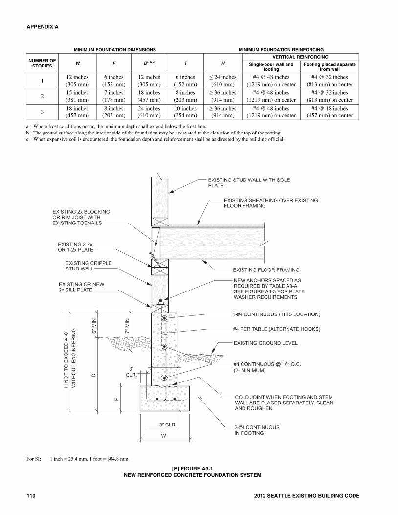
APPENDIX A
110 2012 SEATTLE EXISTING BUILDING CODE
a. Where frost conditions occur, the minimum depth shall extend below the frost line. b. The ground surface along the interior side of the foundation may be excavated to the elevation of the top of the footing. c. When expansive soil is encountered, the foundation depth and reinforcement shall be as directed by the building official.
MINIMUM FOUNDATION DIMENSIONS MINIMUM FOUNDATION REINFORCING
NUMBER OF STORIES W F Da, b, c T H
VERTICAL REINFORCING
Single-pour wall and footing
Footing placed separate from wall
112 inches(305 mm)
6 inches(152 mm)
12 inches(305 mm)
6 inches(152 mm)
≤ 24 inches(610 mm)
#4 @ 48 inches(1219 mm) on center
#4 @ 32 inches(813 mm) on center
215 inches(381 mm)
7 inches(178 mm)
18 inches(457 mm)
8 inches(203 mm)
≥ 36 inches(914 mm)
#4 @ 48 inches(1219 mm) on center
#4 @ 32 inches(813 mm) on center
318 inches(457 mm)
8 inches(203 mm)
24 inches(610 mm)
10 inches(254 mm)
≥ 36 inches(914 mm)
#4 @ 48 inches(1219 mm) on center
#4 @ 18 inches(457 mm) on center
For SI: 1 inch = 25.4 mm, 1 foot = 304.8 mm.
[B] FIGURE A3-1NEW REINFORCED CONCRETE FOUNDATION SYSTEM
19_ChA3_Seattle_Existing_12.fm Page 110 Thursday, October 31, 2013 12:37 PM

APPENDIX A
2012 SEATTLE EXISTING BUILDING CODE 111
a. Where frost conditions occur, the minimum depth shall extend below the frost line. b. The ground surface along the interior side of the foundation may be excavated to the elevation of the top of the footing. c. When expansive soil is encountered, the foundation depth and reinforcement shall be as directed by the building official.
MINIMUM FOUNDATION DIMENSIONS MINIMUM FOUNDATION REINFORCINGNUMBER OF
STORIES W F D a, b, c T H VERTICAL REINFORCING
HORIZONTAL REINFORCING
1 12 inches (305 mm)
6 inches (152 mm)
12 inches (305 mm)
6 inches (152 mm)
≤ 24 inches (610 mm)
#4 @ 24 inches(610 mm) on center
#4 continuous at top of stem wall
2 15 inches (381 mm)
7 inches (178 mm)
18 inches (457 mm)
8 inches (203 mm)
≥ 24 inches(610 mm)
#4 @ 24 inches(610 mm) on center
#4 @ 16 inches (406 mm) on center
3 18 inches (457 mm
8 inches (203 mm)
24 inches (610 mm)
10 inches (254 mm)
≥ 36 inches (914 mm)
#4 @ 24 inches(610 mm) on center
#4 @ 16 inches (406 mm) on center
For SI: 1 inch = 25.4 mm, 1 foot = 304.8 mm.
[B] FIGURE A3-2NEW MASONRY CONCRETE FOUNDATION
19_ChA3_Seattle_Existing_12.fm Page 111 Thursday, October 31, 2013 12:37 PM

APPENDIX A
112 2012 SEATTLE EXISTING BUILDING CODE
For SI: 1 inch = 25.4 mm. NOTES:1. Plate washers shall comply with the following:
1/2 in. anchor or bolt—3 in. x 3 in. x 0.229 in. minimum.5/8 in. anchor or bolt—3 in. x 3 in. x 0.229 in. minimum.
2. See Figure A3-5 or A3-6 for cripple wall bracing.
[B] FIGURE A3-3SILL PLATE BOLTING TO EXISTING FOUNDATION
19_ChA3_Seattle_Existing_12.fm Page 112 Thursday, October 31, 2013 12:37 PM

APPENDIX A
2012 SEATTLE EXISTING BUILDING CODE 113
For SI: 1 inch = 25.4 mm, 1 foot = 304.8 mm.NOTES:1. If shim space exceeds 11/2 in., alternate details will be required.2. Where required, single piece shim shall be foundation grade redwood or preservative-treated wood. If perservative-treated wood is used, it shall be isolated
from the foundation system with a moisture barrier.
[B] FIGURE A3-4AALTERNATE SILL PLATE ANCHORING IN EXISTING FOUNDATION—
WITHOUT CRIPPLE WALLS AND FLOOR FRAMING NOT PARALLEL TO FOUNDATIONS
19_ChA3_Seattle_Existing_12.fm Page 113 Thursday, October 31, 2013 12:37 PM

APPENDIX A
114 2012 SEATTLE EXISTING BUILDING CODE
For SI: 1 inch = 25.4 mm.
[B] FIGURE A3-4BALTERNATE SILL PLATE ANCHOR TO EXISTING FOUNDATION WITHOUT CRIPPLE
WALL AND FLOOR FRAMING PARALLEL TO FOUNDATIONS
For SI: 1 inch = 25.4 mm.
[B] FIGURE A3-4CSILL PLATE ANCHORING TO EXISTING FOUNDATION—ALTERNATE CONNECTION FOR BATTERED FOOTING
19_ChA3_Seattle_Existing_12.fm Page 114 Thursday, October 31, 2013 12:37 PM

APPENDIX A
2012 SEATTLE EXISTING BUILDING CODE 115
For SI: 1 inch = 25.4 mm. NOTE: See Figure A3-3 for sill plate anchoring.
[B] FIGURE A3-5CRIPPLE WALL BRACING WITH NEW WOOD STRUCTURAL PANEL ON EXTERIOR FACE OF CRIPPLE STUDS
19_ChA3_Seattle_Existing_12.fm Page 115 Thursday, October 31, 2013 12:37 PM

APPENDIX A
116 2012 SEATTLE EXISTING BUILDING CODE
For SI: 1 inch = 25.4 mm.
[B] FIGURE A3-6CRIPPLE WALL BRACING WITH WOOD STRUCTURAL PANEL ON INTERIOR FACE OF CRIPPLE STUDS
19_ChA3_Seattle_Existing_12.fm Page 116 Thursday, October 31, 2013 12:37 PM

APPENDIX A
2012 SEATTLE EXISTING BUILDING CODE 117
For SI: 1 inch = 25.4 mm.
[B] FIGURE A3-7PARTIAL CRIPPLE STUD WALL ELEVATION
19_ChA3_Seattle_Existing_12.fm Page 117 Thursday, October 31, 2013 12:37 PM

APPENDIX A
118 2012 SEATTLE EXISTING BUILDING CODE
NEW FRAMING CLIP (FLAT) AT EACHBLOCK TO PLATE WITH A MINIMUMHORIZONTAL CAPACITY OF 450POUNDS. SPACE AS INDICATED ABOVE
NEW 2x SOLID BLOCKING INSTALLEDTO FIT TIGHTLY BETWEEN FLOORJOISTS
EXISTING CRIPPLE STUD WALLSEE FIGURE A3-5 FOR BRACING
EXISTING 2-2x OR 1-2x PLATE
EXISTING RIM JOIST OR BLOCKINGWITH EXISTING NAILING TO BEVERIFIED PER A304.1.3
WHERE AN EXISTING RIM JOISTOR BLOCKING NAILING CAN NOTBE VERIFIED, PROVIDE A NEWFRAMING CLIP FROM BLOCKS TOTOP PLATE WITH A MINIMUMHORIZONTAL CAPACITY OF 450POUNDS AS FOLLOWS:
3-STORY: 16 O.C.
2-STORY: 32 O.C.
1-STORY: 48 O.C.
�
�
�
WHERE AN EXISTING RIM JOISTOR BLOCKING IS NOT PRESENT,PROVIDE NEW 2x SOLID BLOCKINGAS FOLLOWS:3-STORY: EVERY JOIST SPACE2-STORY: EVERY JOIST SPACE
ABOVE BRACED PANELS,ALTERNATE JOIST SPACESAT OTHER LOCATIONS
1-STORY: 2-2x OR 1-2x PLATE
ALTERNATE DETAIL FOR FLUSH CONDITION
For SI: 1 inch = 25.4 mm, 1 pound = 4.4 N. NOTE: See manufacturing instructions for nail sizes associated with metal framing clips.
[B] FIGURE A3-8ATYPICAL FLOOR TO CRIPPLE WALL CONNECTION (FLOOR JOISTS NOT PARALLEL TO FOUNDATIONS)
19_ChA3_Seattle_Existing_12.fm Page 118 Thursday, October 31, 2013 12:37 PM

APPENDIX A
2012 SEATTLE EXISTING BUILDING CODE 119
For SI: 1 inch = 25.4 mm, 1 pound = 4.4 N. NOTE: See manufacturing instructions for nail sizes associated with metal framing clips.
[B] FIGURE A3-8BTYPICAL FLOOR TO CRIPPLE WALL CONNECTION (FLOOR JOISTS PARALLEL TO FOUNDATIONS)
19_ChA3_Seattle_Existing_12.fm Page 119 Thursday, October 31, 2013 12:37 PM

APPENDIX A
120 2012 SEATTLE EXISTING BUILDING CODE
WHERE AN EXISTING RIM JOISTOR BLOCKING IS NOT PRESENT,PROVIDE NEW 2x SOLID BLOCKINGAS FOLLOWS:3-STORY: EVERY JOIST SPACE2-STORY: EVERY JOIST SPACE ABOVE
BRACED PANELS, ALTERNATE JOISTSPACES AT OTHER LOCATIONS
1-STORY: ALTERNATE JOIST SPACES
EXISTING END FLOOR JOISTOR BLOCKING WITH EXISTINGTOENAILS TO BE VERIFIEDPER A304.1.3
EXISTING 2x MUDSILL
EXISTING END JOIST WITHEXISTING TOENAILS TO BEVERIFIED PER A304.1.4
EXISTING 2x MUDSILL
EXISTING FOUNDATION WALL
EXISTING GROUND LEVEL
WHERE AN EXISTING END JOISTOR BLOCK TOE NAILING CAN NOTBE VERIFIED, PROVIDE A NEWFRAMING CLIP FROM END JOISTOR BLOCK TO MUDSILL ASFOLLOWS:
3-STORY: 16 O.C.
2-STORY: 32 O.C.
1-STORY: 48 O.C.NEW FRAMING CLIP MINIMUMALLOWABLE CAPACITY IS 450POUNDS
�
�
�
WHERE AN EXISTING END JOISTOR BLOCK TOE NAILING CAN NOTBE VERIFIED, PROVIDE A NEWFRAMING CLIP FROM END JOISTOR BLOCK TO MUDSILL ASFOLLOWS:
3-STORY: 16 O.C.
2-STORY: 32 O.C.
1-STORY: 48 O.C.NEW FRAMING CLIP MINIMUMALLOWABLE CAPACITY IS 450POUNDS
�
�
�
FLOOR JOISTS NOT PARALLEL TO FOUNDATIONS
FLOOR JOISTS PARALLEL TO FOUNDATIONS
For SI: 1 inch = 25.4 mm.NOTES:1. See Section A304.3 for sill plate anchorage.2. See manufacturing instructions for nail sizes associated with metal framing clips.
[B] FIGURE A3-8CTYPICAL FLOOR TO MUDSILL CONNECTIONS
19_ChA3_Seattle_Existing_12.fm Page 120 Thursday, October 31, 2013 12:37 PM

APPENDIX A
2012 SEATTLE EXISTING BUILDING CODE 121
NEW 2x BLOCK WITH 3-10d NAILSPRE-DRILL BLOCK TO PRECLUDE SPLITTING
NEW 2x BLOCKING. SEE REQUIREMENTSABOVE
FLOOR JOISTS PARALLEL TO FOUNDATION
WHERE EXISTING NAILING FROM EXISTING RIMJOIST TO TOP PLATE CAN NOT BE VERIFIED,
PROVIDE NEW ¾ WOOD STRUCTURAL PANELBLOCKING. SEE REQUIREMENTS ABOVE.
�
EXISTING RIM JOIST WITHEXISTING NAILING TO BEVERIFIED PER A304.1.4
WHERE AN EXISTING RIM JOIST OR BLOCKING
IS NOT PRESENT, PROVIDE NEW ¾ WOODSTRUCTURAL PANEL BLOCKING INSTALLED TOFIT TIGHTLY BETWEEN FLOOR JOISTS. NAIL
WITH 8d NAILS AT 4 ON CENTER TO TOPPLATE AND SILL PLATE. SPACE BLOCKS ASFOLLOWS:3-STORY: EVERY JOIST SPACE2-STORY: EVERY JOIST SPACE ABOVE
BRACED PANELS, ALTERNATE JOISTSPACES AT OTHER LOCATIONS
1-STORY: ALTERNATE JOIST SPACE
�
�EXISTING CRIPPLE STUD WALL.SEE FIGURE A3.5 FOR BRACING
NEW 2x BLOCK BETWEEN EACHSTUD WHEN EXISTING CRIPPLESTUD WALL HAS SINGLE TOP PLATE.NAIL TO TOP PLATE WITH 3-10dNAILS. (PRE-DRILL BLOCK)
EXISTING 2-2x OR 1-2x PLATE
FLOOR JOISTS NOT PARALLEL TO FOUNDATION
For SI: 1 inch = 25.4 mm, 1 pound = 4.4N. NOTE: See Section A304.4 for cripple wall bracing.
[B] FIGURE A3-9ALTERNATE FLOOR FRAMING TO CRIPPLE WALL CONNECTION
19_ChA3_Seattle_Existing_12.fm Page 121 Thursday, October 31, 2013 12:37 PM

APPENDIX A
122 2012 SEATTLE EXISTING BUILDING CODE
2 FT.8 IN.
2 FT.8 IN.
Bracing determination:1-story building each end and not less than 40% of wall length.1⎯
Transverse wall 30 ft. 0.40 = 12 ft. minimum panel length = 4 ft. 0 in.⎯ ×2-story building each end and not less than 50% of wall length.1⎯
Longitudinal wall 40 ft. 0.50 = 20 ft. 0 in. minimum of bracing.⎯ ×3-story building each end and not less than 80% of wall length.1⎯
Transverse wall 30 ft. 0.80 = 24 ft. 0 in. minimum of bracing.⎯ ×1 2See Table A3-A for buildings with both plaster walls and roofing exceeding 6 psf (287 N/m ).
NOTES:Bracing shown assumes cripple stud height of 24 in.
Minimum panel length shall be two times the cripple studwall height.
All panels along a wall shall be nearly equal in length andnearly equal in spacing along the wall. Wherever possible,panels should be laid out to begin and end on studs whilemaintaining required panel lengths. This may require theoccasional addition of a new stud.
1.
2.
3.
REQUIRED BRACING FOR 1-STORY BUILDING
RE
QU
IRE
D B
RA
CIN
G N
OT
SH
OW
N F
OR
TH
ISW
ALL
30 FT.
11 FT. 10 IN. 11 FT. 10 IN.
8 FT. 8 FT. 8 FT.
4 FT. 5 FT. 4 IN.5 FT. 4 IN.
4 FT.
4 FT.
4 FT.
4 FT.
4 FT.
4 FT.
4 FT.
5 FT. 4 IN.
5 FT. 4 IN.
(4' E
AC
H)
(4 F
T.E
AC
H)
40 F
T.
RE
QU
IRE
D B
RA
CIN
G F
OR
2-S
TOR
Y B
UIL
DIN
G
REQUIRED BRACING FOR 3-STORY BUILDING
For SI: 1 inch = 25.4 mm, 1 foot = 304.8 mm.
[B] FIGURE A3-10—FLOOR PLAN-CRIPPLE WALL BRACING LAYOUT
19_ChA3_Seattle_Existing_12.fm Page 122 Thursday, October 31, 2013 12:37 PM

2012 SEATTLE EXISTING BUILDING CODE 123
CHAPTER A4
EARTHQUAKE RISK REDUCTIONIN WOOD-FRAME RESIDENTIAL BUILDINGSWITH SOFT, WEAK OR OPEN FRONT WALLS
SECTION A401GENERAL
[B] A401.1 Purpose. The purpose of this chapter is to pro-mote public welfare and safety by reducing the risk of deathor injury that may result from the effects of earthquakes onexisting wood-frame, multiunit residential buildings. Theground motions of past earthquakes have caused the loss ofhuman life, personal injury and property damage in thesetypes of buildings. This chapter creates minimum standardsto strengthen the more vulnerable portions of these structures.When fully followed, these minimum standards will improvethe performance of these buildings but will not necessarilyprevent all earthquake-related damage.
[B] A401.2 Scope. The provisions of this chapter shall applyto all existing Occupancy Group R-1 and R-2 buildings ofwood construction or portions thereof where the structure hasa soft, weak, or open-front wall line, and there exists one ormore stories above.
SECTION A402 DEFINITIONS
Notwithstanding the applicable definitions, symbols andnotations in the building code, the following definitions shallapply for the purposes of this chapter:
[B] ASPECT RATIO. The span-width ratio for horizontaldiaphragms and the height-length ratio for shear walls.
[B] GROUND FLOOR. Any floor whose elevation is imme-diately accessible from an adjacent grade by vehicles orpedestrians. The ground floor portion of the structure doesnot include any floor that is completely below adjacentgrades.
[B] NONCONFORMING STRUCTURAL MATERIALS.Wall bracing materials other than wood structural panels ordiagonal sheathing.
[B] OPEN-FRONT WALL LINE. An exterior wall line,without vertical elements of the lateral force-resisting system,that requires tributary seismic forces to be resisted by dia-phragm rotation or excessive cantilever beyond parallel linesof shear walls. Diaphragms that cantilever more than 25 per-cent of the distance between lines of lateral force-resistingelements from which the diaphragm cantilevers shall be con-sidered excessive. Exterior exit balconies of 6 feet (1829 mm)or less in width shall not be considered excessive cantilevers.
[B] RETROFIT. An improvement of the lateral force-resist-ing system by alteration of existing structural elements oraddition of new structural elements.
[B] SOFT WALL LINE. A wall line whose lateral stiffnessis less than that required by story drift limitations or deforma-
tion compatibility requirements of this chapter. In lieu ofanalysis, a soft wall line may be defined as a wall line in astory where the story stiffness is less than 70 percent of thestory above for the direction under consideration.
[B] STORY. A story as defined by the building code, includ-ing any basement or underfloor space of a building with crip-ple walls exceeding 4 feet (1219 mm) in height.
[B] STORY STRENGTH. The total strength of all seismic-resisting elements sharing the same story shear in the direc-tion under consideration.
[B] WALL LINE. Any length of wall along a principal axisof the building used to provide resistance to lateral loads. Par-allel wall lines separated by less than 4 feet (1219 mm) shallbe considered one wall line for the distribution of loads.
[B] WEAK WALL LINE. A wall line in a story where thestory strength is less than 80 percent of the story above in thedirection under consideration.
SECTION A403 ANALYSIS AND DESIGN
[B] A403.1 General. All modifications required by the provi-sions in this chapter shall be designed in accordance with theInternational Building Code provisions for new construction,except as modified by this chapter.
Exception: Buildings for which the prescriptive measuresprovided in Section A404 apply and are used.
No alteration of the existing lateral force-resisting systemor vertical load-carrying system shall reduce the strength orstiffness of the existing structure, unless the altered structurewould remain in conformance to the building code and thischapter.
[B] A403.2 Scope of analysis. This chapter requires thealteration, repair, replacement or addition of structural ele-ments and their connections to meet the strength and stiffnessrequirements herein. The lateral-load-path analysis shallinclude the resisting elements and connections from the wooddiaphragm immediately above any soft, weak or open-frontwall lines to the foundation soil interface or to the uppermoststory of a podium structure comprised of steel, masonry, orconcrete structural systems that supports the upper, wood-framed structure. Stories above the uppermost story with asoft, weak, or open-front wall line shall be considered in theanalysis but need not be modified. The lateral-load-pathanalysis for added structural elements shall also include eval-uation of the allowable soil-bearing and lateral pressures inaccordance with the building code. Where any portion of abuilding within the scope of this chapter is constructed on orinto a slope steeper than one unit vertical in three units hori-
�
�
20_ChA4_Seattle_Existing_12.fm Page 123 Thursday, October 31, 2013 12:37 PM

APPENDIX A
124 2012 SEATTLE EXISTING BUILDING CODE
zontal (33-percent slope), the lateral force-resisting system atand below the base level diaphragm shall be analyzed for theeffects of concentrated lateral forces at the base caused bythis hillside condition.
Exception: When an open-front, weak or soft wall lineexists because of parking at the ground floor of a two-story building and the parking area is less than 20 percentof the ground floor area, then only the wall lines in theopen, weak or soft directions of the enclosed parking areaneed comply with the provisions of this chapter.
[B] A403.3 Design base shear and design parameters. Thedesign base shear in a given direction shall be permitted to be75 percent of the value required for similar new constructionin accordance with the building code. The value of R used inthe design of the strengthening of any story shall not exceedthe lowest value of R used in the same direction at any storyabove. The system overstrength factor, Δ0, and the deflectionamplification factor, Cd, shall not be less than the largestrespective value corresponding to the R factor being used inthe direction under consideration.
Exceptions:
1. For structures assigned to Seismic Design CategoryB, values of R, Δ0 and Cd shall be permitted to bebased on the seismic force-resisting system beingused to achieve the required strengthening.
2. For structures assigned to Seismic Design CategoryC or D, values of R, Δ0 and Cd shall be permitted tobe based on the seismic force-resisting systembeing used to achieve the required strengthening,provided that when the strengthening is complete,the strengthened structure will not have an extremeweak story irregularity defined as Type 5b in ASCE7 Table 12.3-2.
3. For structures assigned to Seismic Design CategoryE, values of R, Δ0 and Cd shall be permitted to bebased on the seismic force-resisting system beingused to achieve the required strengthening, pro-vided that when the strengthening is complete, thestrengthened structure will not have an extreme softstory, a weak story, or an extreme weak story irreg-ularity defined, respectively, as Types 1b, 5a and5b in ASCE 7 Table 12.3-2.
[B] A403.4 Story drift limitations. The calculated storydrift for each retrofitted story shall not exceed the allowabledeformation compatible with all vertical load-resisting ele-ments and 0.025 times the story height. The calculated storydrift shall not be reduced by the effects of horizontal dia-phragm stiffness but shall be increased when these effectsproduce rotation. Drift calculations shall be in accordancewith the building code.
[B] A403.4.1 Pole structures. The effects of rotation andsoil stiffness shall be included in the calculated story driftwhere lateral loads are resisted by vertical elements whoserequired depth of embedment is determined by pole for-mulas. The coefficient of subgrade reaction used indeflection calculations shall be based on a geotechnical
investigation conducted in accordance with the buildingcode.
[B] A403.5 P Δ effects. The requirements of the buildingcode shall apply, except as modified herein. All structuralframing elements and their connections not required bydesign to be part of the lateral force-resisting system shall bedesigned and/or detailed to be adequate to maintain supportof design dead plus live loads when subjected to the expecteddeformations caused by seismic forces. The stress analysis ofcantilever columns shall use a buckling factor of 2.1 for thedirection normal to the axis of the beam.
[B] A403.6 Ties and continuity. All parts of the structureincluded in the scope of Section A403.2 shall be intercon-nected as required by the building code.
[B] A403.7 Collector elements. Collector elements shall beprovided that can transfer the seismic forces originating inother portions of the building to the elements within the scopeof Section A403.2 that provide resistance to those forces.
[B] A403.8 Horizontal diaphragms. The strength of anexisting horizontal diaphragm sheathed with wood structuralpanels or diagonal sheathing need not be investigated unlessthe diaphragm is required to transfer lateral forces from verti-cal elements of the seismic force-resisting system above thediaphragm to elements below the diaphragm because of anoffset in placement of the elements.
Wood diaphragms with stories above shall not be allowedto transmit lateral forces by rotation or cantilever except asallowed by the building code; however, rotational effectsshall be accounted for when unsymmetric wall stiffnessincreases shear demands.
Exception: Diaphragms that cantilever 25 percent or lessof the distance between lines of lateral load-resisting ele-ments from which the diaphragm cantilevers may transmittheir shears by cantilever, provided that rotational effectson shear walls parallel and perpendicular to the load aretaken into account.
[B] A403.9 Wood-framed shear walls. Wood-framed shearwalls shall have strength and stiffness sufficient to resist theseismic loads and shall conform to the requirements of thissection.
[B] A403.9.1 Gypsum or cement plaster products. Gyp-sum or cement plaster products shall not be used to pro-vide lateral resistance in a soft or weak story or in a storywith an open-front wall line, whether or not new elementsare added to mitigate the soft, weak or open-front condi-tion.
[B] A403.9.2 Wood structural panels.
[B] A403.9.2.1 Drift limit. Wood structural panelshear walls shall meet the story drift limitation of Sec-tion A403.4. Conformance to the story drift limitationshall be determined by approved testing or calculation.Individual shear panels shall be permitted to exceed themaximum aspect ratio, provided the allowable storydrift and allowable shear capacities are not exceeded.
[B] A403.9.2.2 Openings. Shear walls are permitted tobe designed for continuity around openings in accor-
�
�
20_ChA4_Seattle_Existing_12.fm Page 124 Thursday, October 31, 2013 12:37 PM

APPENDIX A
2012 SEATTLE EXISTING BUILDING CODE 125
dance with the building code. Blocking and steel strap-ping shall be provided at corners of the openings totransfer forces from discontinuous boundary elementsinto adjoining panel elements. Alternatively, perforatedshear wall provisions of the building code are permittedto be used.
[B] A403.9.3 Hold-down connectors.
[B] A403.9.3.1 Expansion anchors in tension. Expan-sion anchors that provide tension strength by frictionresistance shall not be used to connect hold-downdevices to existing concrete or masonry elements.
[B] A403.9.3.2 Required depth of embedment. Therequired depth of embedment or edge distance for theanchor used in the hold-down connector shall be pro-vided in the concrete or masonry below any plain con-crete slab unless satisfactory evidence is submitted tothe code official that shows that the concrete slab andfootings are of monolithic construction.
SECTION A404 PRESCRIPTIVE MEASURES FOR WEAK STORY
[B] A404.1 Limitation. These prescriptive measures shallapply only to two-story buildings and only when deemedappropriate by the code official. These prescriptive measuresrely on rotation of the second floor diaphragm to distributethe seismic load between the side and rear walls of the groundfloor open area. In the absence of an existing floor diaphragmof wood structural panel or diagonal sheathing, a new woodstructural panel diaphragm of minimum thickness of 3/4 inch(19 mm) and with 10d common nails at 6 inches (152 mm) oncenter shall be applied.
[B] A404.1.1 Additional conditions. To qualify for theseprescriptive measures, the following additional conditionsneed to be satisfied by the retrofitted structure:
1. Diaphragm aspect ratio L/W is less than 0.67, whereW is the diaphragm dimension parallel to the soft,weak or open-front wall line and L is the distance inthe orthogonal direction between that wall line andthe rear wall of the ground floor open area.
2. Minimum length of side shear walls = 20 feet (6096mm).
3. Minimum length of rear shear wall = three-fourthsof the total rear wall length.
4. No plan or vertical irregularities other than a soft,weak or open-front wall line.
5. Roofing weight less than or equal to 5 pounds persquare foot (240 N/m2).
6. Aspect ratio of the full second floor diaphragmmeets the requirements of the building code fornew construction.
[B] A404.2 Minimum required retrofit.
[B] A404.2.1 Anchor size and spacing. The anchor sizeand spacing shall be a minimum of 3/4 inch (19 mm) indiameter at 32 inches (813 mm) on center. Where existinganchors are inadequate, supplemental or alternative
approved connectors (such as new steel plates bolted to theside of the foundation and nailed to the sill) shall be used.
[B] A404.2.2 Connection to floor above. Shear wall topplates shall be connected to blocking or rim joist at upperfloor with a minimum of 18-gage galvanized steel angleclips 41/2 inches (114 mm) long with 12-8d nails spaced nofarther than 16 inches (406 mm) on center, or by equiva-lent shear transfer methods.
[B] A404.2.3 Shear wall sheathing. The shear wallsheathing shall be a minimum of 15/32 inch (11.9 mm) 5-PlyStructural I with 10d nails at 4 inches (102 mm) on centerat edges and 12 inches (305 mm) on center at field; blockedall edges with 3 by 4 board or larger. Where existing sillplates are less than 3-by thick, place flat 2-by on top of sillbetween studs, with flat 18-gage galvanized steel clips 41/2
inches (114 mm) long with 12-8d nails or 3/8-inch-diameter(9.5 mm) lags through blocking for shear transfer to sillplate. Stagger nailing from wall sheathing between existingsill and new blocking. Anchor new blocking to foundationas specified above.
[B] A404.2.4 Shear wall hold-downs. Shear walls shallbe provided with hold-down anchors at each end. Twohold-down anchors are required at intersecting corners.Hold-downs shall be approved connectors with a mini-mum 5/8-inch-diameter (15.9 mm) threaded rod or otherapproved anchor with a minimum allowable load of 4,000pounds (17.8 kN). Anchor embedment in concrete shallnot be less than 5 inches (127 mm). Tie-rod systems shallnot be less than 5/8 inch (15.9 mm) in diameter unlessusing high-strength cable. Threaded rod or high-strengthcable elongation shall not exceed 5/8 inch (15.9 mm) usingdesign forces.
SECTION A405 MATERIALS OF CONSTRUCTION
[B] A405.1 New materials. New materials shall meet therequirements of the International Building Code, exceptwhere allowed by this chapter.
[B] A405.2 Allowable foundation and lateral pressures.The use of default values from the building code for continu-ous and isolated concrete spread footings shall be permitted.For soil that supports embedded vertical elements, SectionA403.4.1 shall apply.
[B] A405.3 Existing materials. The physical condition,strengths, and stiffnesses of existing building materials shallbe taken into account in any analysis required by this chapter.The verification of existing materials conditions and theirconformance to these requirements shall be made by physicalobservation, material testing or record drawings as deter-mined by the registered design professional subject to theapproval of the code official.
[B] A405.3.1 Wood-structural-panel shear walls.
[B] A405.3.1.1 Existing nails. When the required cal-culations rely on design values for common nails orsurfaced dry lumber, their use in construction shall beverified by exposure.
�
�
�
20_ChA4_Seattle_Existing_12.fm Page 125 Thursday, October 31, 2013 12:37 PM

APPENDIX A
126 2012 SEATTLE EXISTING BUILDING CODE
[B] A405.3.1.2 Existing plywood. When verificationof the existing plywood is by use of record drawingsalone, plywood shall be assumed to be of three plies.
[B] A405.3.2 Existing wood framing. Wood framing ispermitted to use the design stresses specified in the build-ing code under which the building was constructed orother stress criteria approved by the code official.
[B] A405.3.3 Existing structural steel. All existingstructural steel shall be permitted to be assumed to complywith ASTM A 36. Existing pipe or tube columns shall beassumed to be of minimum wall thickness unless verifiedby testing or exposure.
[B] A405.3.4 Existing concrete. All existing concretefootings shall be permitted to be assumed to be plain con-crete with a compressive strength of 2,000 pounds persquare inch (13.8 MPa). Existing concrete compressivestrength taken greater than 2,000 pounds per square inch(13.8 MPa) shall be verified by testing, record drawings ordepartment records.
[B] A405.3.5 Existing sill plate anchorage. The analysisof existing cast-in-place anchors shall be permitted toassume proper anchor embedment for purposes of evaluat-ing shear resistance to lateral loads.
SECTION A406 INFORMATION REQUIRED TO BE ON THE PLANS
[B] A406.1 General. The plans shall show all informationnecessary for plan review and for construction and shall accu-rately reflect the results of the engineering investigation anddesign. The plans shall contain a note that states that this ret-rofit was designed in compliance with the criteria of thischapter.
[B] A406.2 Existing construction. The plans shall showexisting diaphragm and shear wall sheathing and framingmaterials; fastener type and spacing; diaphragm and shearwall connections; continuity ties; and collector elements. Theplans shall also show the portion of the existing materials thatneeds verification during construction.
[B] A406.3 New construction.
[B] A406.3.1 Foundation plan elements. The foundationplan shall include the size, type, location and spacing of allanchor bolts with the required depth of embedment, edgeand end distance; the location and size of all shear wallsand all columns for braced frames or moment frames; ref-erenced details for the connection of shear walls, bracedframes or moment-resisting frames to their footing; andreferenced sections for any grade beams and footings.
[B] A406.3.2 Framing plan elements. The framing planshall include the length, location and material of shearwalls; the location and material of frames; references ondetails for the column-to-beam connectors, beam-to-wallconnections and shear transfers at floor and roof dia-phragms; and the required nailing and length for wall topplate splices.
[B] A406.3.3 Shear wall schedule, notes and details.Shear walls shall have a referenced schedule on the plans
that includes the correct shear wall capacity in pounds perfoot (N/m); the required fastener type, length, gauge andhead size; and a complete specification for the sheathingmaterial and its thickness. The schedule shall also showthe required location of 3-inch (76 mm) nominal or two 2-inch (51 mm) nominal edge members; the spacing of sheartransfer elements such as framing anchors or added sillplate nails; the required hold-down with its bolt, screw ornail sizes; and the dimensions, lumber grade and speciesof the attached framing member.
Notes shall show required edge distance for fastenerson structural wood panels and framing members; requiredflush nailing at the plywood surface; limits of mechanicalpenetrations; and the sill plate material assumed in thedesign. The limits of mechanical penetrations shall also bedetailed showing the maximum notching and drilled holesizes.
[B] A406.3.4 General notes. General notes shall show therequirements for material testing, special inspection andstructural observation.
SECTION A407 QUALITY CONTROL
[B] A407.1 Structural observation, testing and inspection.Structural observation, in accordance with Section 1709 ofthe International Building Code, shall be required for allstructures in which seismic retrofit is being performed inaccordance with this chapter. Structural observation shallinclude visual observation of work for conformance to theapproved construction documents and confirmation of exist-ing conditions assumed during design.
Structural testing and inspection for new constructionmaterials shall be in accordance with the building code,except as modified by this chapter. �
20_ChA4_Seattle_Existing_12.fm Page 126 Thursday, October 31, 2013 12:37 PM

2012 SEATTLE EXISTING BUILDING CODE 127
CHAPTER A5
EARTHQUAKE HAZARD REDUCTION IN EXISTING CONCRETE BUILDINGS
SECTION A501 PURPOSE
[B] A501.1 Purpose. The purpose of this chapter is to pro-mote public safety and welfare by reducing the risk of deathor injury that may result from the effects of earthquakes onconcrete buildings and concrete frame buildings.
The provisions of this chapter are intended as minimumstandards for structural seismic resistance, and are establishedprimarily to reduce the risk of life loss or injury. Compliancewith the provisions in this chapter will not necessarily pre-vent loss of life or injury or prevent earthquake damage to therehabilitated buildings.
SECTION A502 SCOPE
[B] A502.1 Scope. The provisions of this chapter shall applyto all buildings having concrete floors or roofs supported byreinforced concrete walls or by concrete frames and columns.This chapter shall not apply to buildings with roof dia-phragms that are defined as flexible diaphragms by the build-ing code, and shall not apply to concrete frame buildings withmasonry infilled walls.
Buildings that were designed and constructed in accor-dance with the seismic provisions of the 1993 BOCANational Building Code, the 1994 Standard Building Code,the 1976 Uniform Building Code, the 2000 InternationalBuilding Code or later editions of these codes shall bedeemed to comply with these provisions, unless the seismic-ity of the region has increased since the design of the build-ing.
Exception: This chapter shall not apply to concrete build-ings where Seismic Design Category A is permitted.
SECTION A503 GENERAL REQUIREMENTS
[B] A503.1 General. This chapter provides a three-tieredprocedure to evaluate the need for seismic rehabilitation ofexisting concrete buildings. The evaluation shall show thatthe existing building is in compliance with the appropriatepart of the evaluation procedure as described in SectionsA505, A506 and A507, or shall be modified to conform to therespective acceptance criteria. This chapter does not precludea building from being evaluated or modified to conform tothe acceptance criteria using other well-established proce-dures, based on rational methods of analysis in accordancewith principles of mechanics and approved by the authorityhaving jurisdiction.
[B] A503.2 Properties of cast-in-place materials. Exceptwhere specifically permitted herein, the stress-strain relation-
ship of concrete and reinforcement shall be determined frompublished data or by testing. All available information,including building plans, original calculations and design cri-teria, site observations, testing and records of typical materi-als and construction practices prevalent at the time ofconstruction, shall be considered when determining materialproperties.
For Tier 3 analysis, expected material properties shall beused in lieu of nominal properties in the calculation ofstrength, stiffness and deformabiltity of building components.
The procedure for testing and determination of materialproperties shall be from Section 6.2 of ASCE 41-06.
[B] A503.3 Structural observation, testing and inspection.Structural observation, in accordance with Section 1709 ofthe International Building Code shall be required for allstructures in which seismic retrofit is being performed inaccordance with this chapter. Structural observation shallinclude visual observation of work for conformance to theapproved construction documents and confirmation of exist-ing conditions assumed during design.
Structural testing and inspection for new constructionmaterials shall be in accordance with the building code,except as modified by this chapter.
SECTION A504 SITE GROUND MOTION
[B] A504.1 Site ground motion for Tier 1 analysis. Theearthquake loading used for the determination of demand onelements of the structure shall correspond to that required byASCE 31 Tier 1.
[B] A504.2 Site ground motion for Tier 2 analysis. Theearthquake loading used for the determination of demand onelements and the structure shall conform to 75 percent of thatrequired by the building code.
[B] A504.3 Site ground motion for Tier 3 analysis. The siteground motion shall be an elastic design response spectrumprepared in conformance to the building code but havingspectral acceleration values equal to 75 percent of the codedesign response spectrum. The spectral acceleration valuesshall be increased by the occupancy importance factor whenrequired by the building code.
SECTION A505 TIER 1 ANALYSIS PROCEDURE
[B] A505.1 General. Structures conforming to the require-ments of the ASCE 31 Tier 1, Screening Phase, are permittedto be shown to be in conformance to this chapter by submis-sion of a report to the building official as described in thissection.
21_ChA5_Seattle_Existing_12.fm Page 127 Thursday, October 31, 2013 12:37 PM

APPENDIX A
128 2012 SEATTLE EXISTING BUILDING CODE
[B] A505.2 Evaluation report. The registered design profes-sional shall prepare a report summarizing the analysis con-ducted in compliance with this section. As a minimum, thereport shall include the following items:
1. Building description.
2. Site inspection summary.
3. Summary of reviewed record documents.
4. Earthquake design data used for the evaluation of thebuilding.
5. Completed checklists.
6. Quick-check analysis calculations.
7. Summary of deficiencies.
SECTION A506 TIER 2 ANALYSIS PROCEDURE
[B] A506.1 General. A Tier 2 analysis includes an analysisusing the following linear methods: Static or equivalent lat-eral force procedures. A linear dynamic analysis may be usedto determine the distribution of the base shear over the heightof the structure. The analysis, as a minimum, shall address allpotential deficiencies identified in Tier 1, using proceduresspecified in this section.
If a Tier 2 analysis identifies a nonconforming condition,such condition shall be modified to conform to the accep-tance criteria. Alternatively, the design professional maychoose to perform a Tier 3 analysis to verify the adequacy ofthe structure.
[B] A506.2 Limitations. A Tier 2 analysis procedure may beused if:
1. There is no in-plane offset in the lateral force-resistingsystem.
2. There is no out-of-plane offset in the lateral force-resisting system.
3. There is no torsional irregularity present in any story. Atorsional irregularity may be deemed to exist in a storywhen the maximum story drift, computed includingaccidental torsion, at one end of the structure transverseto an axis is more than 1.2 times the average of thestory drifts at the two ends of the structure.
4. There is no weak story irregularity at any floor level onany axis of the building. A weak story is one in whichthe story strength is less than 80 percent of that in thestory above. The story strength is the total strength ofall seismic-resisting elements sharing the story shearfor the direction under consideration.
Exception: Static or equivalent lateral force proceduresshall not be used if:
1. The building is more than 100 feet (30 480 mm) inheight.
2. The building has a vertical mass or stiffness irregu-larity (soft story). Mass irregularity shall be consid-ered to exist where the effective mass of any storyis more than 150 percent of the effective mass of
any adjacent story. A soft story is one in which thelateral stiffness is less than 70 percent of that in thestory above or less than 80 percent of the averagestiffness of the three stories above.
3. The building has a vertical geometric irregularity.Vertical geometric irregularity shall be consideredto exist where the horizontal dimension of the lat-eral force-resisting system in any story is more than130 percent of that in an adjacent story.
4. The building has a nonorthogonal lateral force-resisting system.
[B] A506.3 Analysis procedure. A structural analysis shallbe performed for all structures in accordance with therequirements of the building code, except as modified in Sec-tion A506. The response modification factor, R, shall beselected based on the type of seismic force-resisting systememployed and shall comply with the requirements of Section304.4.1 ((301.1.4.1)).
[B] A506.3.1 Mathematical model. The three-dimen-sional mathematical model of the physical structure shallrepresent the spatial distribution of mass and stiffness ofthe structure to an extent that is adequate for the calcula-tion of the significant features of its distribution of lateralforces. All concrete and masonry elements shall beincluded in the model of the physical structure.
Exception: Concrete or masonry partitions that are iso-lated from the concrete frame members and the floorabove.
Cast-in-place reinforced concrete floors with span-to-depth ratios less than three-to-one may be assumed to berigid diaphragms. Other floors, including floors con-structed of precast elements with or without a reinforcedconcrete topping, shall be analyzed in conformance to thebuilding code to determine if they must be consideredsemi-rigid diaphragms. The effective in-plane stiffness ofthe diaphragm, including effects of cracking and disconti-nuity between precast elements, shall be considered. Park-ing structures that have ramps rather than a single floorlevel shall be modeled as having mass appropriately dis-tributed on each ramp. The lateral stiffness of the rampmay be calculated as having properties based on theuncracked cross section of the slab exclusive of beams andgirders.
[B] A506.3.2 Component stiffness. Component stiffnessshall be calculated based on the approximate values shownin Table 6-5 of ASCE 41.
[B] A506.4 Design, detailing requirements and structuralcomponent load effects. The design and detailing of newcomponents of the seismic force-resisting system shall com-ply with the requirements of the International Building Code,unless specifically modified herein.
[B] A506.5 Acceptance criteria. The calculated strength of amember shall not be less than the load effects on that mem-ber.
[B] A506.5.1 Load combinations. For load and resistancefactor design (strength design), structures and all portions
21_ChA5_Seattle_Existing_12.fm Page 128 Thursday, October 31, 2013 12:37 PM

APPENDIX A
2012 SEATTLE EXISTING BUILDING CODE 129
thereof shall resist the most critical effects from the com-binations of factored loads prescribed in the building code.
Exception: For concrete beams and columns, the sheareffect shall be determined based on the most criticalload combinations prescribed in the building code. Theshear load effect, because of seismic forces, shall bemultiplied by a factor of Cd, but combined shear loadeffect need not be greater than Ve, as calculated inaccordance with Equation A5-4. Mpr1 and Mpr2 are theend moments, assumed to be in the same direction(clockwise or counter clockwise), based on steel tensilestress being equal to 1.25 fy, where fy is the specifiedyield strength.
(Equation A5-1)
where:
Wg = Total gravity loads on the beam
[B] A506.5.2 Determination of the strength of mem-bers. The strength of a member shall be determined bymultiplying the nominal strength of the member by astrength reduction factor, φ. The nominal strength of themember shall be determined in accordance with the build-ing code.
SECTION A507TIER 3 ANALYSIS PROCEDURE
[B] A507.1 General. A Tier 3 evaluation shall be performedusing the nonlinear procedures of Section 6.3.1.2.2. of ASCE41. The general assumptions and requirements of Section 6.0,excluding concrete frames with in-fills shall be used in theevaluation. Site-ground motions in accordance with SectionA504.3 are permitted for this evaluation.
VeMpr1 Mpr2+
L-----------------------------
Wg2
-------±=
21_ChA5_Seattle_Existing_12.fm Page 129 Thursday, October 31, 2013 12:37 PM

130 2012 SEATTLE EXISTING BUILDING CODE
21_ChA5_Seattle_Existing_12.fm Page 130 Thursday, October 31, 2013 12:37 PM

2012 SEATTLE EXISTING BUILDING CODE 131
CHAPTER A6
REFERENCED STANDARDS
ASCE/SEI American Society of Civil EngineersStructural Engineering Institute1801 Alexander Bell DriveReston, VA 20191-4400
Standard Referencedreference in codenumber Title section number
7—10 Minimum Design Loads for Buildings and Other Structures with Supplement No. 1 . . . . . . . . . . .A104, A403.331—03 Seismic Evaluation of Existing Buildings . . . . . . . . . . . . . . . . . . . . . . . . . . . . . . . . . . . . . . . . . . . A504.1, A505.141—06 Seismic Rehabilitation of Existing Buildings . . . . . . . . . . . . . . . . . . . . . . . . . . . . . . . . A503.2, A506.3.2, A507.1
ASTM ASTM International 100 Barr Harbor Drive West Conshohocken, PA 19428-2959
Standard Referencedreference in codenumber Title section number
A653/A653M—08 Standard Specification for Steel Sheet, Zinc Coated (Galvanized) or Zinc-Iron Alloy-Coated (Galvannealed) by Hot-Dip Process . . . . . . . . . . . . . . . . . . . . . . . . . . . . . . . . .A304.2.6
C90—2003 Standard Specification for Load-bearing Concrete Masonry Units. . . . . . . . . . . . . . . . . . . . . . . . . . . . . .A505.2.3C496—96 Standard Test Method for Splitting Tensile Strength of Cylindrical Concrete Specimens . . . . .A104, A106.3.3.2E 488—10 Test Method for Strength of Anchors in Concrete and Masonry Elements. . . . . . . . . . . . . . . . . . . . . . . . . A107.5E519—00e1 Standard Test Method for Diagonal Tension (Shear) in Masonry Assemblages. . . . . . . . . . . . .A104, A106.3.3.2
DOC U.S. Department of Commerce National Institute of Standards and Technology 100 Bureau Drive Stop 3460 Gaithersburg, MD 20899
Standard Referencedreference in codenumber Title section number
PS-1—95 Construction and Industrial Plywood. . . . . . . . . . . . . . . . . . . . . . . . . . . . . . . . . . . . . . . . . . . . . . . . . . . . . . . .A302 PS-2—92 Performance Standard for Wood-based Structural-use Panels . . . . . . . . . . . . . . . . . . . . . . . . . . . . . . . . . . . .A302
ICC International Code Council 500 New Jersey Avenue, NW, 6th Floor Washington, DC 20001
Standard Referencedreference in codenumber Title section number
BNBC—93 BOCA National Building Code® . . . . . . . . . . . . . . . . . . . . . . . . . . . . . . . . . . . . . . . . . . . . . . . . . . . . . . . . . . .A502 BNBC—96 BOCA National Building Code® . . . . . . . . . . . . . . . . . . . . . . . . . . . . . . . . . . . . . . . . . . . . . . . . . . . . . . . . . . .A502 BNBC—99 BOCA National Building Code® . . . . . . . . . . . . . . . . . . . . . . . . . . . . . . . . . . . . . . . . . . . . . . . . . . . . . . . . . . .A202 IBC—00 International Building Code® . . . . . . . . . . . . . . . . . . . . . . . . . . . . . . . . . . . . . . . . . . . . . . . . . . . . . A202.1, A502.1IBC—03 International Building Code® . . . . . . . . . . . . . . . . . . . . . . . . . . . . . . . . . . . . . . . . . . . . . . . . . . . . . A202.1, A502.1IBC—06 International Building Code® . . . . . . . . . . . . . . . . . . . . . . . . . . . . . . . . . . . . . . . . . . . . . . . . . . . . . A202.1, A502.1IBC—09 International Building Code® . . . . . . . . . . . . . . . . . . . . . . . . . . . . . . . . . . . . . . . . . . . . . . . . . . . . . A202.1, A502.1
22_ChA6_RefStand_Seattle_Existing_12.fm Page 131 Thursday, October 31, 2013 12:37 PM

APPENDIX A
132 2012 SEATTLE EXISTING BUILDING CODE
ICC—continuedIBC—12 International Building Code® . . . . . . . . . . . . . . . . . . . . . . . . . . A102.2, A108.2, A202.1, A203, A206.3, A206.9,
A403.1, A405.1, A407.1, A502.1, A503.3, A506.4,SBC—94 Standard Building Code® . . . . . . . . . . . . . . . . . . . . . . . . . . . . . . . . . . . . . . . . . . . . . . . . . . . . . . . . . . . . . . . . A502 SBC—97 Standard Building Code® . . . . . . . . . . . . . . . . . . . . . . . . . . . . . . . . . . . . . . . . . . . . . . . . . . . . . . . . . . . . . . . . A502 SBC—99 Standard Building Code® . . . . . . . . . . . . . . . . . . . . . . . . . . . . . . . . . . . . . . . . . . . . . . . . . . . . . . . . . . . . . . . . A202 UBC—76 Uniform Building Code®. . . . . . . . . . . . . . . . . . . . . . . . . . . . . . . . . . . . . . . . . . . . . . . . . . . . . . . . . . . . . . . . . A502 UBC—97 Uniform Building Code®. . . . . . . . . . . . . . . . . . . . . . . . . . . . . . . . . . A102.2, A103, A104, A108.2, A202, A203,
A206.2, A301.2, A401.2, A403.1, A403.2, A403.3,A403.4, A403.7, A403.11.2.2, A405.2.3,
A406.2, A406.3.2.1, A408.1, A502UBC—Standard 21-4 Hollow and Solid Load-bearing Concrete Masonry Units . . . . . . . . . . . . . . . . . . . . . . . . . . . . . . . . . . . . . .A106.2 UBC—Standard 21-6 In-place Masonry Shear Tests. . . . . . . . . . . . . . . . . . . . . . . . . . . . . . . . . . . . . . . . . . . . . . . . . . . . . . . . . . . . . A104 UBC—Standard 21-7 Tests of Anchors in Unreinforced Masonry . . . . . . . . . . . . . . . . . . . . . . . . A105.3, A107.3, A107.4, Table A1-EUBC—Standard 21-8 Pointing of Unreinforced Masonry Walls. . . . . . . . . . . . . . . . . . . . . . . . . . . . . . . . . . . . . . . . . . A103, A106.3.3.9UBC—Standard 23-2 Construction and Industrial Plywood . . . . . . . . . . . . . . . . . . . . . . . . . . . . . . . . . . . . . . . . . . . . . . . . . .A403.11.2.1
22_ChA6_RefStand_Seattle_Existing_12.fm Page 132 Thursday, October 31, 2013 12:37 PM