Embed Size (px)
Citation preview

Ain Shams Engineering Journal (2011) 2, 33–42
Ain Shams University
Ain Shams Engineering Journal
www.elsevier.com/locate/asejwww.sciencedirect.com
CIVIL ENGINEERING
Seismic response of base isolated liquid storage
ground tanks
Ayman A. Seleemah *, Mohamed El-Sharkawy 1
Structural Engineering Department, Faculty of Engineering, Tanta University, Tanta, Egypt
Received 3 December 2010; revised 5 February 2011; accepted 5 May 2011
Available online 14 June 2011
*
E-
els1
20
El
Pe
do
KEYWORDS
Ground liquid storage tanks;
Seismic isolation systems;
Aspect ratio;
Isolation period;
Broad;
Slender
Corresponding author. Tel.:
mail addresses: seleemah55@
[email protected] (M. E
Tel.: +20 10 00 73 131.
90-4479 � 2011 Ain Shams
sevier B.V. All rights reserve
er review under responsibilit
i:10.1016/j.asej.2011.05.001
Production and h
+20 10
yahoo.co
l-Sharka
Universit
d.
y of Ain
osting by E
Abstract In this paper, the seismic responses of base-isolated broad and slender cylindrical liquid
storage ground tanks are investigated. Three types of isolation systems are considered. The seismic
responses are compared with the corresponding responses of non-isolated tanks. Moreover, a para-
metric study was conducted to evaluate the effect of tank aspect ratio, isolation period, and friction
coefficient of the FPS system on key responses of the tank. It was found that, base isolation is quite
effective in reducing the earthquake response of ground liquid storage tanks. Generally speaking,
50–90% reductions in both base shear and impulsive displacement responses were observed. The
convective displacement was observed to be 20–70% higher than that associated with fixed base
tanks leading to an essential need of increasing the clear height above the liquid surface. Base iso-
lation was found to be more effective for slender tanks in comparison with broad tanks.� 2011 Ain Shams University. Production and hosting by Elsevier B.V.
All rights reserved.
66 19 311.
m (A.A. Seleemah), eng_ms_
wy).
y. Production and hosting by
Shams University.
lsevier
1. Introduction
Liquid storage tanks have always been an important link in the
distribution of water, chemical and refined petroleum prod-ucts. The seismic performance of these tanks has been a matterof special importance, beyond the economic value of the struc-
ture, due to the requirement to remain functional after a majorearthquake event. Water supply is essential immediately fol-lowing destructive earthquakes, not only to cope with possible
subsequent fires, but also to avoid outbreaks of disease. An-other reason is the potential danger associated with the failureof tanks containing highly inflammable products, which canlead to extensive uncontrolled fire, while possible spillage of
such contents might cause extensive environmental damageand affect populated areas.
In the past, failure of a number of ground supported liquid
storage tanks occurred. Such failures generated lot of interest

34 A.A. Seleemah, M. El-Sharkawy
to safeguard these tanks against seismic forces. Due to the fact
that conventional strengthening of tanks does not ensure abso-lute safety during strong earthquake ground motions, engi-neering researchers are developing other techniques such asbase isolation for the protection of liquid storage tanks. For
example, Malhotra [1] presented a new method for seismic iso-lation of cylindrical, ground-supported, liquid storage steeltanks by disconnecting the wall of the tank from the base plate
and supporting it on a ring of horizontally flexible bearings.Wang et al. [2] studied the seismic isolation of rigid cylindricalground tanks using friction pendulum bearings (FPS). Shri-
mali and Jangid [3] investigated the seismic response of liquidstorage tanks isolated by lead-rubber bearings under bi-direc-tional earthquake excitation. Shrimali and Jangid [4] studied
the response of liquid storage ground tanks isolated by slidingsystems. Seleemah [5] studied the performance of various de-grees of frictional coefficients of sliding isolation systems dueto short and long-term contamination of the sliding interfaces.
Shrimali and Jangid [6] presented three analytical studies forthe seismic response of base-isolated ground liquid storagetanks. Cho et al. [7] studied the seismic response of base-iso-
lated liquid storage tanks considering fluid–structure–soilinteraction in the time domain using a coupling method thatcombines the finite elements and boundary elements. Grego-
riou et al. [8] conducted a seismic analysis of liquefied naturalgas tanks isolated by rubber bearings. The problem was solvednumerically by means of a detailed finite element model, takinginto account fluid–structure interaction effects. Shekari et al.
[9] studied seismically isolated cylindrical liquid storage tanksusing a coupled boundary element-finite element to representthe fluid–structure interaction. Abalı and Uckan [10] studied
both broad and slender tanks isolated by FPS bearings. Theyutilized Haroun and Housner’s [11] model to represent thefluid. Moreover, they took the effects of overturning moments
and vertical accelerations on the variation of the axial load ofthe bearings into consideration.
In this paper, the seismic response of cylindrical liquid stor-
age ground tanks isolated by elastomeric or sliding bearings isinvestigated. The specific objectives of the study are: (i) toinvestigate the effectiveness of elastomeric or sliding bearingsfor seismic isolation of liquid storage tanks by comparing
the response of the tank with and without isolation; (ii) toinvestigate the influence of various parameters, such as tankaspect ratio, isolation period, and the friction coefficient of
an FPS system, on peak responses of the tanks. The presentstudy includes two types of elastomeric bearings (NZ andHDRB systems) and one type of sliding bearings (FPS system).
Figure 1 Mechanical analog proposed by Haroun and Housner
[11] for flexible cylindrical tank.
2. Simplified fluid–structure interaction
The seismic analysis of liquid storage tanks is complicated dueto fluid–structure interaction of the system. Therefore, com-plex actions must be taken into account. First of all, the con-
tained liquid is interacting with the tank wall. Seismic energy istransferred from the ground to the fluid through the motion ofthe tank. A portion of the liquid accelerates with the tank, act-ing as an added mass; the remaining liquid is assumed to slosh.
Sloshing occurs in the upper part of the liquid, which does notdisplace laterally with the tank wall, generating seismic waves.In an effort to simplify the analysis, Haroun and Housner [11]
developed a three-degree-of-freedom model of a ground-sup-
ported cylindrical tank that takes tank wall flexibility into ac-
count. Following is a review of this model.The contained liquid is considered as incompressible, invis-
cous and has irrotational flow. During the base excitation, theentire tank liquid mass (m) vibrates in three distinct patterns,
such as sloshing or convective mass (mc) (i.e. top liquid masswhich changes the free liquid surface), impulsive mass (mi) (i.e.intermediate liquid mass vibrating along with tank wall) and ri-
gidmass (mr) (i.e. the lower liquidmasswhich rigidlymoveswiththe tank wall). While there are several modes in which sloshingand impulsive masses vibrates, the response can be predicted by
considering only the first sloshing mode and the first impulsivemode. Therefore, the continuous liquid with flexible tank canbe modeled as three lumped masses (see Fig. 1).
The convective and impulsive masses are connected to thetank by corresponding equivalent springs. The various equiva-lent masses and associated natural frequencies of the tank li-quid are expressed as:
Yc ¼mc
mð1Þ
Yi ¼mi
mð2Þ
Yr ¼mr
mð3Þ
m ¼ pR2Hqw ð4Þ
xi ¼P
H
ffiffiffiffiffiE
qs
sð5Þ
xc ¼ffiffiffiffiffiffiffiffiffiffiffiffiffiffiffiffiffiffiffiffiffiffiffiffiffiffiffiffiffiffiffiffiffiffiffiffiffiffiffiffiffiffiffi1:84
g
R
� �tanhð1:84SÞ
rð6Þ
where H is the liquid height, R is the tank radius, S=H/R is
the aspect ratio (ratio of the liquid height to radius of thetank), the non-dimensional parameters Yc, Yi and Yr are massratios associated with convective, impulsive and rigid masses
of the tank liquid, respectively; qw is the mass density of liquid;xc and xi are the convective and impulsive frequencies, respec-tively; E and qs are the modulus of elasticity and density oftank wall, respectively; g is the gravity acceleration and P is
a non-dimensional parameter associated with frequency ofimpulsive mass. The parameters Yc, Yi, Yr and P are functionof the aspect ratio of the tank S, given by the following
relation.

Yc
Yi
Yr
P
8>>><>>>:
9>>>=>>>;¼
1:01327 �0:8757 0:35708 0:06692 0:00439
�0:15467 1:21716 �0:62839 0:14434 �0:0125�0:01599 0:86356 �0:30941 0:04083 0
0:037085 0:084302 �0:05088 0:012523 �0:0012
26664
37775
1
S
S2
S3
S4
8>>>>>><>>>>>>:
9>>>>>>=>>>>>>;
ð7Þ
Seismic response of base isolated liquid storage ground tanks 35
The centeroid of the equivalent masses mc, mi and mr are ata height Hc, Hi and Hr from bottom of the tank, respectively.They are expressed in terms of non-dimensional form as:
lc
li
lr
8><>:
9>=>; ¼
0:52410 �0:10792 0:33958 �0:19357 0:04791 �0:00450:44086 �0:11972 0:16752 �0:06089 0:00751 0
0:44233 0:08445 0:07916 �0:02677 0:00326 0
264
375
1
S
S2
S3
S4
S5
8>>>>>>>><>>>>>>>>:
9>>>>>>>>=>>>>>>>>;
ð8Þ
The effective heights Hc, Hi and Hr in terms of liquid height,H, are expressed as:
Hc ¼ lcH ð9ÞHi ¼ liH ð10ÞHr ¼ lrH ð11Þ
The equivalent stiffness and damping of the convective andimpulsive masses are expressed as:
Kc ¼ mcx2c ð12Þ
Ki ¼ mix2i ð13Þ
Cc ¼ 2fcmcxc ð14ÞCi ¼ 2fimixi ð15Þ
where fc and fi are the damping ratios of convective and
impulsive masses, respectively.
3. Modeling of isolation systems
Program 3D-BASIS-ME designed by Tsopelas et al. [12] wasutilized in this study to model the tanks including the isolation
Figure 2 Idealized hysteretic force–displacement relation of NZ
system.
system. Following is a brief review of the models of differentisolation systems used in this study.
3.1. Lead rubber bearing system (NZ system)
The behavior of lead-rubber bearings is represented by a bilin-
ear hysteretic model. Fig. 2 shows an idealized force–displace-ment relation of a lead-rubber bearing. The characteristicstrength, Qd, is related to the lead plug area. The model is char-acterized by three parameters, namely, the post-to-pre-yielding
stiffness ratio a, the yield force Fy, and the yield displacementDy for lead-rubber bearings in which the elastic stiffness Kelastic
is approximately equal to 6.5 the post yield stiffness Kpost-elastic,
i.e., a = 0.154, the yield displacement and yield force can beestimated utilizing the expressions given by FEMA [13], Yanget al. [14], and ASCE [15].
3.2. High damping rubber bearing system (HDRB system)
The behavior of HDRB system is represented by stiffeninghysteretic model. Fig. 3 shows an idealized force–displacementrelation of a high-damping rubber bearing. The model is char-acterized by six parameters, namely, the characteristic strength
Q, tangent stiffness K1, tangent stiffness K2, Displacement lim-it D1, displacement limit D2, and yield displacement Dy.
3.3. Friction pendulum system (FPS system)
The behavior of friction pendulum bearings is represented by
hysteretic model. Fig. 4 shows an idealized force–displacement
DISPLACEMENT
FORCE
D2D1
K1
K2
-D2 -D1
DY
Q
Figure 3 Stiffening hysteretic model of HDRB system.

Figure 4 Modeling of a friction pendulum bearings: (a) idealized
force–displacement loop and (b) relation of friction coefficient
with velocity of sliding and pressure.
36 A.A. Seleemah, M. El-Sharkawy
loop of a friction pendulum bearing. The model is character-ized by six parameters, namely, the radius of curvature ofthe concave surface of the bearing R, maximum coefficientof sliding friction at almost zero pressure fmax, minimum coef-
ficient of sliding friction fmin, constant which controls the tran-
Table 1 Properties of tanks.
Type of tank H
(ft)
R
(ft)
S=H/R ts of wall
(in.)
ts of basemat
(ft)
Broad 40 60 0.667 1 1.5
Slender 74.4 44 1.69 1.898 1.75
Figure 5 Idealized tank model of (a)
sition of coefficient of sliding friction from maximum to
minimum, a; yield displacement, Dy; and initial normal forceat the sliding interface (static condition), N. The coefficientof sliding friction is modeled by the equation suggested byTsopelas et al. [12] as following:
ls ¼ fmax � ðfmax � fminÞ expð�ajU�jÞ ð16Þwhere U� is the velocity of sliding, a is a parameter which con-trols the variation of the coefficient of friction with velocity.Values of parameters fmax, fmin and a have been reported in
Tsopelas et al. [12], and Mokha et al. [16]. In general, param-eters fmax, fmin and a are functions of bearing pressure as shownin Fig. 4b. While the overturning effect was taken into consid-
eration, the frictional properties were assumed to be onlydependent on the instantaneous sliding velocity.
4. Numerical analysis of broad and slender tanks
The properties of the studied cylindrical broad and slender
tanks are given in Table 1. The tank is considered as filled toa height H with water. For steel wall the modulus of elasticityis taken as E = 29000 Kips/in.2 and the unit weight,qs = 0.49 Kips/ft3. The liquid storage tank is represented by
the mechanical system illustrated in Fig. 1 for broad or slendertanks on the basis of the theory of Haroun and Housner [11]which takes into account the deformability of the tank wall
and sloshing of the fluid. For the convective mass, damping ra-tio is considered to be 0.005 (damping for water) and for theimpulsive mass, damping is defined to be 0.02 for a steel cylin-
drical tank responding in the linear elastic range.Fig. 5 represents the model of broad and slender tanks that
were used in this study. The oscillators in Fig. 5 are repre-
sented as single storey, shear-type structures connected to thecenter of mass of the basemat. The rigid mass is rigidly at-tached to the concrete basemat, raising its weight. For com-plete investigation of the seismic behavior of liquid storage
tanks, key response parameters will be compared. The main re-sponse quantities of interest are the base shear over weight ofthe tank (Vs/W), the convective displacement (Xc), the impul-
sive displacement (Xi) and the isolation system displacement(Xb).
broad tank and (b) slender tank.

-7.0
-3.5
0.0
3.5
7.0
-1.0
-0.5
0.0
0.5
1.0
-15.0
-7.5
0.0
7.5
15.0
Non-isolated N-ZHDRB FPS
(Bas
e di
sp.)
,Xb
(in)
(I
mpu
lsiv
e di
sp.)
,Xi (
in)
(Con
vect
ive
disp
.), X
c (i
n)
Seismic response of base isolated liquid storage ground tanks 37
5. Results and discussions
5.1. Effect of base isolation
Time variations of various response quantities of broad andslender tanks subjected to El-Centro ground excitation are
illustrated in Figs. 6 and 7, respectively. The responses areshown for both isolated and non-isolated conditions. It is ob-served that base shear over weight (Vs/W) and impulsive dis-
placement (Xi) of the isolated tanks for all isolation systemsare significantly reduced in comparison to those without isola-tion system. These results are in agreement with those observed
by Wang et al. [2], Shrimali and Jangid [3,4], Seleemah [5],Gregoriou et al. [8], Shekari et al. [9] and Abalı and Uckan[10]. The reduction in base shear leads to reduction in the tank
wall thickness and hence more economic design. Moreover, thereduction in the impulsive displacement means reduction in theactions that cause local buckling in the tank wall. Suchreductions will, of course, lead to a superior tank performance
during earthquakes. It is also observed that, as a result of iso-lation, there is a moderate increase in the convective displace-ment. This is due to the high flexibility associated with the
convective mass which brings its natural period closer to that
0 5 10 15 20-0.70
-0.35
0.00
0.35
0.70
Time (sec)
(Bas
e sh
ear/
wei
ght)
,Vs/
W
Figure 7 Time variation of response quantities of slender ground
tank under El-Centro earthquake (Tb = 2 s, fb = 0.1,
fmax = 4.5% and fmin = 3%).
0 5 10 15 20-0.4
-0.2
0.0
0.2
0.4
(Bas
e sh
ear/
wei
ght)
,Vs/
W
-4
-2
0
2
4
(Bas
e di
sp.)
,Xb
(in)
-0.50
-0.25
0.00
0.25
0.50
Time (sec)
(Im
puls
ive
disp
.),X
i (in
)
-15-10
-505
1015
Non-isolated N-ZHDRB FPS
(Con
vect
ive
disp
.),X
c (i
n)
Figure 6 Time variation of response quantities of broad ground
tank under El-Centro earthquake (Tb = 2 s, fb = 0.1,
fmax = 4.5% and fmin = 3%).
of the isolated tank period. However, such behavior has nopractical consequences except for the need to increase the clear
height above the liquid surface.The peak response quantities for broad and slender tanks
under the earthquakes considered are tabulated in Table 2. It
is observed that, the average reduction percentage in the baseshear are 63% and 81%; and in the impulsive displacement are73% and 88% for broad and slender tanks, respectively. Fur-
ther, the reduction of base shear and impulsive displacementfor slender tank is significantly greater than that for the broadtank, implying that the seismic isolation is more effective forslender tanks. This observation is in agreement with that re-
ported by Shekari et al. [9]. Overall results indicate that theFPS system is more effective to reduce both base shear andbase displacement responses in comparison to NZ or HDRB
systems.
5.2. Effect of tank aspect ratio
In order to investigate the behavior for a wide practical rangeof liquid storage tanks, the effect of change aspect ratio (H/R)
from 0.5 to 4.0 on the peak response quantities are shown inFigs. 8 and 9. It should be mentioned that in all cases of aspectratios the volume of the water tank was kept constant at452389 ft3 and the total isolated weight was kept constant at

(a) (b)
0 1 2 3 40
1
2
3Kobe, 1995
Vs/
W
(Aspect ratio),(H/R)
0 1 2 3 40
1
2
3Northridge, 1994
Vs/
W
0 1 2 3 40
1
2
3Imperial Valley, 1940 Non-isolated N-Z
HDRB FPS
Vs/
W
0 1 2 3 40
5
10
15
20Kobe, 1995
Xb(
in)
(Aspect ratio),(H/R)
0 1 2 3 40
5
10
15
20Northridge, 1994
Xb(
in)
0 1 2 3 40
5
10
15
20Imperial Valley, 1940
N-Z HDRB FPS
Xb(
in)
Figure 8 Effect of aspect ratio on peak response of the isolated ground tank (Tb = 2 s, fb = 0.1, fmax = 4.5% and fmin = 3%): (a) base
shear over weight and (b) base displacement..
(a) (b)
0 1 2 3 40
10
20
30
40Kobe, 1995
Xc
(in)
(Aspect ratio), (H/R)
0 1 2 3 40
10
20
30
40Northridge, 1994
Xc
(in)
0 1 2 3 40
10
20
30
40Imperial Valley, 1940 Non-isolated N-Z
HDRB FPS
Xc
(in)
0 1 2 3 40
5
10
15
20Kobe, 1995
Xi (
in)
(Aspect ratio), (H/R)
0 1 2 3 40
5
10
15
20Northridge, 1994
Xi (
in)
0 1 2 3 40
5
10
15
20Imperial Valley, 1940 Non-isolated N-Z
HDRB FPS
Xi (
in)
Figure 9 Effect of aspect ratio on peak response of the isolated ground tank (Tb = 2 s, fb = 0.1, fmax = 4.5% and fmin = 3%): (a)
impulsive displacement and (b) convective displacement.
38 A.A. Seleemah, M. El-Sharkawy

0
3
6
9
12
15
18
Xb
(in)
7
14
21
28
35Broad tank (H/R=0.67)
Xc
(in)
Slender tank (H/R=1.69)
2.0 2.5 3.0 3.5 4.0 4.5 5.0 2.0 2.5 3.0 3.5 4.0 4.5 5.00.0
0.2
0.4
0.6
Vs/
W
Tb (sec) Tb (sec)
Imperial Valley, 1940Northridge, 1994Kobe, 1995
NZHDRBFPS
Figure 10 Effect of isolation period on peak seismic response of isolated tanks.
Table 2 Peak responses of broad and slender ground tanks.
Earthquake Type
of tank
Non-isolated tank Isolated tank
Xc (in.) Xi (in.) Vs/W N-Z system HDRB system FPS system
Xc (in.) Xi (in.) Xb (in.) Vs/W Xc (in.) Xi (in.) Xb (in.) Vs/W Xc (in.) Xi (in.) Xb (in.) Vs/W
Imperial
Valley 1940
Broad 10.91 0.38 0.39 10.70 0.05 3.30 0.10 10.26 0.06 2.62 0.10 10.90 0.07 2.32 0.10
Slender 8.50 0.93 0.64 10.95 0.15 6.67 0.17 10.53 0.14 4.88 0.16 10.26 0.19 4.23 0.15
Northridge
N90S 1994
Broad 14.30 0.64 0.75 16.30 0.12 8.15 0.20 16.91 0.14 8.62 0.26 16.86 0.14 6.46 0.21
Slender 16.30 3.80 2.41 29.30 0.26 13.00 0.31 27.15 0.34 10.98 0.38 25.10 0.25 8.63 0.26
Kobe
N00S 1995
Broad 8.93 0.51 0.78 15.50 0.18 14.80 0.34 20.20 0.30 14.74 0.57 15.70 0.22 13.50 0.39
Slender 11.10 3.54 2.19 17.95 0.28 12.55 0.30 17.93 0.51 13.60 0.51 16.11 0.30 11.10 0.33
Seismic response of base isolated liquid storage ground tanks 39
31550 Kips. It is observed that the base shear of the non-iso-lated tank is very sensitive to the change of the aspect ratioand to the change of the driving motion also. On the other
hand, using any of the three isolation systems considerably re-duced the base shear. Moreover, the base shear of isolatedtanks is not significantly influenced by the aspect ratio and it
0
10
20
30
40Broad tank (H/R=0.67)
Xc
(in)
0
8
16
24
Xb
(in)
0.050 0.075 0.100 0.125 0.1500.0
0.2
0.4
0.6
0.8
1.0
1.2
Slender tank (H/R=1.69)
Vs/
W
µmax (sec)
0.050 0.075 0.100 0.125 0.150
Imperial Valley, 1940Northridge, 1994Kobe, 1995
µmax (sec)
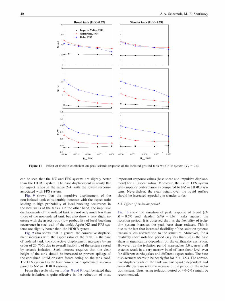
Figure 11 Effect of friction coefficient on peak seismic response of the isolated ground tank with FPS system (Tb = 2 s).
40 A.A. Seleemah, M. El-Sharkawy
can be seen that the NZ and FPS systems are slightly better
than the HDRB system. The base displacement is nearly flatfor aspect ratios in the range 2–4, with the lowest responseassociated with FPS system.
Fig. 9 shows that the impulsive displacement of thenon-isolated tank considerably increases with the aspect ratioleading to high probability of local buckling occurrence in
the steel walls of the tanks. On the other hand, the impulsivedisplacements of the isolated tank are not only much less thanthose of the non-isolated tank but also show a very slight in-crease with the aspect ratio (low probability of local buckling
occurrence in steel wall of the tank). Again NZ and FPS sys-tems are slightly better than the HDRB system.
Fig. 9 also shows that in general the convective displace-
ment increases with the aspect ratio of the tank. In the caseof isolated tank the convective displacement increases by anorder of 20–70% due to overall flexibility of the system caused
by seismic isolation. Such increase requires that the clearheight of the tank should be increased to prevent spillage ofthe contained liquid or extra forces acting on the tank roof.
The FPS system has the least convective displacement as com-pared to NZ or HDRB systems.
From the results shown in Figs. 8 and 9 it can be stated thatseismic isolation is quite effective in the reduction of most
important response values (base shear and impulsive displace-
ment) for all aspect ratios. Moreover, the use of FPS systemgives superior performance as compared to NZ or HDRB sys-tems. Nevertheless, the clear height over the liquid surface
should be increased especially in slender tanks.
5.3. Effect of isolation period
Fig. 10 show the variation of peak response of broad (H/R= 0.67) and slender (H/R= 1.69) tanks against theisolation period. It is observed that, as the flexibility of isola-
tion system increases the peak base shear reduces. This isdue to the fact that increased flexibility of the isolation systemstransmits less acceleration to the structure. Moreover, for a
relatively short isolation period (say less than 3.0 s) the baseshear is significantly dependent on the earthquake excitation.However, as the isolation period approaches 5.0 s, nearly all
systems result in a very narrow band of base shear level evenfor different earthquakes and different aspect ratios. The basedisplacement seems to be nearly flat for T > 3.5 s. The convec-
tive displacements of the tank are earthquake dependent andgenerally decrease with the increase of the period of the isola-tion system. Thus, using isolation period of 4.0–5.0 s might berecommended.

0
10
20
30
40Broad tank (H/R=0.67)
Xc
(in)
0
8
16
24
Xb
(in)
0.1 0.2 0.3 0.4 0.50.0
0.2
0.4
0.6
Slender tank (H/R=1.69)
Vs/
W
ξb (sec)0.1 0.2 0.3 0.4 0.5
Imperial Valley, 1940Northridge, 1994Kobe, 1995
ξb (sec)
Figure 12 Effect of bearing damping on peak seismic response of isolated ground tank with NZ system (Tb = 2 s).
Seismic response of base isolated liquid storage ground tanks 41
5.4. Effect of friction coefficient of FPS system and damping of
NZ system
The effect of coefficient of friction, lmax, and bearing dampingof NZ system on the resulting response of isolated broad and
slender tanks are shown in Figs. 11 and 12, respectively. Gen-erally speaking, increase of the friction coefficient or bearingdamping dissipates more seismic energy and hence causes mostresponse parameters to decrease.
6. Conclusions
From the results of the present study, the following conclu-sions can be stated:
� Base isolation is quite effective in reducing the earthquakeresponse of ground liquid storage tanks, base shear reduc-tions ranged between 50% and 90% and impulsive displace-
ment reductions ranged between 65% and 90%.� The base isolation is more effective for slender tanks incomparison with broad tanks.
� There is a moderate increase (20–70%) in the convectivedisplacement when the tank is seismically isolated especially
for high aspect ratios. Nevertheless, the clear height overthe liquid surface should be increased to overcome such
disadvantage.� Performance of FPS system proved to be better as com-pared to the other isolation systems.� For the non-isolated tanks, the base shear and the impulsive
displacement are significantly affected by the aspect ratioand the exciting earthquake also. On the other hand, forthe isolated tanks, these response parameters are signifi-
cantly reduced and show negligible dependency on theaspect ratio. This holds true for all types of utilized isola-tion systems.
� The impulsive displacements of the non-isolated tanks con-siderably increase with the aspect ratio leading to highprobability of local buckling occurrence in the steel walls
of the tanks. On the other hand, for the isolated tanks theyare not only significantly reduced but also show a negligibleincrease with the aspect ratio leading to low probability oflocal buckling occurrence in steel walls of the tanks.
� Increase in the friction coefficient of FPS system or bearingdamping of NZ system dissipate more seismic energy andhence causes most response parameters to decrease.
� Isolation period of 4.0–5.0 s can be recommended.

42 A.A. Seleemah, M. El-Sharkawy
References
[1] Malhotra PK. New method for seismic isolation of liquid-storage
tanks. J Earthquake Eng Struct Dyn 1997;26:839–47.
[2] Wang YP, Teng MC, Chung KW. Seismic isolation of rigid
cylindrical tanks using friction pendulum bearings. Earthquake
Eng Struct Dyn 2001;30:1083–99.
[3] Shrimali MK, Jangid RS. Non-linear seismic response of base-
isolated liquid storage tanks to bi-directional excitation. Nucl Eng
Des 2002;217:1–20.
[4] Shrimali MK, Jangid RS. Seismic response of liquid storage tanks
isolated by sliding bearings. Eng Struct 2002;24:909–21.
[5] Seleemah AA. Effect of frictional variations of sliding isolation
systems on seismic behavior of isolated liquid storage tanks. Tenth
International Colloquium on Structural and Geotechnical Engi-
neering, Ain Shams Univ., Egypt, 2003.
[6] Shrimali MK, Jangid RS. Seismic analysis of base-isolated liquid
storage tanks. J Sound Vib 2004;275:59–75.
[7] Cho KH, Kim MK, Lim YM, Cho SY. Seismic response of base-
isolated liquid storage tanks considering fluid–structure-soil inter-
action in time domain. J Soil Dyn Earthquake Eng 2004;24:839–52.
[8] Gregoriou VP, Tsinopoulos SV, Karabalis DL. Seismic analysis of
base isolated liquefied natural gas tanks. 5th GRACM Interna-
tional Congress on Computational Mechanics, Limassol., 2005.
[9] Shekari MR, Khaji N, Ahmadi MT. A coupled BE–FE study for
evaluation of seismically isolated cylindrical liquid storage tanks
considering fluid–structure interaction. J Fluids Struct 2009;25:
567–85.
[10] Abalı E, Uckan E. Parametric analysis of liquid storage tanks base
isolated by curved surface sliding bearings. Soil Dyn Earthquake
Eng 2010;30:21–31.
[11] Haroun MA, Housner GW. Seismic design of liquid storage
tanks. J Tech Councils ASCE 1981;107(1):191–207.
[12] Tsopelas PC, Constantinou MC, Reinhorn AM. 3D-BASIS-ME.
Computer program for nonlinear dynamic analysis of seismically
isolated single and multiple structures and liquid storage tanks.
Technical Report MCEER-94-0010, University at Buffalo, State
University of NY, USA, 1994.
[13] Federal Emergency Management Agency (FEMA) 274, 1997.
Chapter 9: Seismic isolation and energy dissipation, October,
Washington, DC.
[14] Yang YB, Chang KC, Yau JD. Earthquake engineering hand-
book. Boca Raton: CRC Press; 2002.
[15] American Society of Civil Engineers (ASCE), 2005. Chapter 17:
Seismic design requirements for seismically isolated structures,
ASCE 7-05.
[16] Mokha AS, Constantinou MC, Reinhorn AM. Experimental
study of friction pendulum isolation system. J Struct Eng
1991;117(4):1201–17.
Ayman Ahmed Seleemah graduated from
Cairo University in 1986 and obtained his
M.Sc. degree from the same university. He
obtained his Ph.D. degree jointly from Cairo
University and the State University of New
York at Buffalo, USA. His fields of interest
include earthquake engineering for buildings
and bridges, seismic isolation of buildings,
tanks, and bridges; seismic energy dissipation
systems and development; offshore structures;
and neural network applications in structural engineering.
Mohamed El-Sayed El-Sharkawy obtained his
M.Sc. degree from Tanta University. His
fields of interest include earthquake engineer-
ing for buildings and bridges, seismic isolation
of buildings, tanks and seismic energy dissi-
pation systems.