Embed Size (px)
Citation preview

Citation: Shinde, J.K. and Symans, M.D. (2010). “Seismic Performance of Light-Framed Wood Structures with Toggle-Braced Fluid Dampers," Proc. of 2010 ASCE Structures Congress, Orlando, FL, May, 2010.
1
Seismic Performance of Light-Framed Wood Structures with Toggle-Braced Fluid Dampers
Jayesh K. Shinde1 and Michael D. Symans2
1Doctoral Student, Dept. of Civil and Environmental Engineering, Rensselaer Polytechnic Institute, 110 Eighth St, Troy, NY 12180; Email: [email protected] 2Associate Professor, Dept. of Civil and Environmental Engineering, Rensselaer Polytechnic Institute, 110 Eighth St, Troy, NY 12180; Tel: (518) 276-6938; Fax: (518) 276-4833; Email: [email protected] (Contact Author) ABSTRACT In recent years, seismic damping systems have been employed in numerous steel and concrete framed buildings. Such systems dissipate a significant portion of the seismic input energy, thereby relieving the energy dissipation demand on the structural framing system and thus reducing damage. As part of a NEESR project to develop a performance-based approach to seismic design of multi-story light-framed wood structures, the application of damping systems to such structures has been evaluated via seismic shaking table tests and numerical simulations. This paper focuses on the results from shaking table tests of wood shear walls employing toggle-braced fluid dampers. Within the context of performance-based seismic design, the effect of the fluid dampers on the deformation demand and hysteretic energy dissipation demand is emphasized. The results demonstrate that toggle-braced fluid dampers provide a significant increase in the seismic resistance of the walls, allowing them to achieve high levels of performance when subjected to strong ground motions. INTRODUCTION Application of seismic protection systems in light-framed wood structures is virtually non-existent within the U.S. as woodframed construction has generally been considered to perform well during earthquakes. However, the 1994 Northridge Earthquake clearly demonstrated the vulnerability of such construction in that extensive, and in many cases unrepairable, damage occurred in thousands of woodframed buildings (Kircher et al. 1997). A comprehensive literature review on the application of advanced seismic protection systems (both base isolation and supplemental damping systems) to woodframed structures is presented by Symans et al. (2002). This study clearly identified the various challenges of the application of seismic protection systems to woodframed structures.
The installation of fluid viscous dampers (Symans and Constantinou 1998) in stiff structures is often less efficient than applications to relatively flexible structures due to potentially small deformations transferred to the dampers. Note that these problems are amplified for woodframed structures where there can be significant displacement transmission losses from different sources (Shinde et al. 2007, Shinde 2009). Different displacement magnification configurations have been proposed in the literature to address the problems associated with stiff structures. Taylor Devices,

Citation: Shinde, J.K. and Symans, M.D. (2010). “Seismic Performance of Light-Framed Wood Structures with Toggle-Braced Fluid Dampers," Proc. of 2010 ASCE Structures Congress, Orlando, FL, May, 2010.
2
Inc., proposed and patented one such system called “the toggle-brace damper system” in 1996 (“Toggle Linkage Seismic Isolation Structure,” U.S. Patent Nos. 5870863 and 5934028, 1996). Constantinou et al. (2001) further verified this system via testing of a single degree-of-freedom steel model.
Phase 2 of the NEESWood benchmark structure test program involved implementation and evaluation of a seismic damping system with a chevron brace configuration (Shinde et al. 2007). Due to a number of factors, including the inherent flexibility in the connections of wood framing systems, engagement of the dampers was limited during these tests and thus the full effectiveness of the dampers was not realized. Based on what was learned from this testing, a new design for the modular damper walls with a toggle-braced configuration was developed. The objective of the study described herein is to experimentally and numerically evaluate the seismic response of light-framed wood shearwalls retrofitted with toggle-braced fluid viscous dampers. A major advantage of using fluid viscous dampers is their capability of dissipating a large amount of energy relative to their size. Studies conducted by Dutil and Symans (2004) have demonstrated the potential of fluid viscous dampers to reduce the energy dissipation demand in woodframed structures. The results of the testing described herein demonstrated that the retrofit provide a significant increase in the seismic resistance of the walls, allowing them to achieve high levels of performance when subjected to strong ground motions. However, the full potential of the retrofit was not realized due to losses in transmission of wall drift to the toggle-bracing system.
SHAKE TABLE TEST PROGRAM Test Specimens and Experimental Setup Specimens were constructed with conventional framing and with modified framing to accomodate a toggle-braced damper assembly (see Figure 1). All shearwalls were designed to simulate the first-story shearwall in a typical two-story woodframed residential structure located in Southern California and were constructed in accordance with the specifications of the 2006 International Building Code (ICC 2006). As shown in Figure 1a and 1b, a single 1.22 m (4 ft) sheathing panel was used in each wall of the test specimens and no finish materials were used.
(a) (b) (c) (d)
Figure 1. Test Specimens on Seismic Shaking Table: (a) Conventional Walls and (b) Retrofitted
Walls (note black steel toggle-braced framing inside of left shearwall) (c) Modular Damper Walls with Toggle Brace Design and (d) Chevron Brace Design (used in Phase 2 Benchmark Tests).
Citation: Shinde, J.K. and Symans, M.D. (2010). “Seismic Performance of Light-Framed Wood Structures with Toggle-Braced Fluid Dampers," Proc. of 2010 ASCE Structures Congress, Orlando, FL, May, 2010.
3
To replicate the seismic loading conditions the shearwall may experience during earthquakes, gravity loading of 58.71 kN (13200 lbs) (or 12.04 kN/m (825 lb/ft)) was applied to both shearwalls. The details of the construction of the test specimens, the test specimen anchorage, the applied dead load and instrumentation are provided by Shinde (2009). Based on what was learned from the Phase 2 Benchmark structure testing (Shinde et al. 2007) (chevron-braced damper design shown in Figure 1d), a new design for the modular damper walls with toggle brace configuration was developed by Taylor Devices, Inc. (see Figure 1c). The new design employs a light steel frame mechanism that surrounds a toggle-braced damper (see Figure 1c). The toggle brace provides a displacement amplification factor, f, of 1.65 which is 65% larger than a chevron-braced configuration. The dampers have force capacity of 11.12 kN (2.5 kips) and a damping coefficient of 1.285 kN-sec/mm (0.225 kip-sec/in).
Seismic Ground Motions For the benchmark structure seismic tests, two historical ground motions were used: an ordinary ground motion and a near-field ground motion (see Table 1). The ordinary ground motion (OGM) (i.e., far-field motion) represented a Design Basis Earthquake (DBE) and the near-field ground motion (NGM) represented a Maximum Credible Earthquake (MCE). The 1994 Northridge Earthquake ground motion recorded at Canoga Park, scaled by a factor of 1.2, was selected as the DBE (10%/50 yr event) and the unscaled 1994 Northridge Earthquake ground motion (Level 5 excitation) recorded at Rinaldi was selected as the MCE (2%/50 yr event). Per Table 1, the DBE and MCE motions are defined as Level 4 and 5 excitation. Due primarily to shaking table limitations, the ground motions used in the toggle-braced damper tests were weaker versions of the Level 4 and 5 motions used in the Phase 2 Benchmark Structure testing (see Table 2).
Table 1 Ground Motions for Benchmark Structure Seismic Shaking Table Tests. Excitation
Level Ground Motions Hazard Level
Scale Factor
PGA (g) E-W N-S Vertical
1 1994 Northridge,
Canoga Park
99.99%/50 years 0.12 0.04 0.05 0.06 2 50%/50 years 0.53 0.19 0.22 0.26 3 20%/50 years 0.86 0.31 0.36 0.42 4 10%/50 years 1.2 0.43 0.50 0.59
5 1994 Northridge,
Rinaldi 2%/50 years 1 0.47 0.84 0.85
Table 2 Ground Motions for Toggle-braced Damper Shaking Table Tests. Note that, in the toggle-braced damper tests, only the y-direction (N-S) motions (stronger component) from the Benchmark Tests were used. Also, for the conventional walls, the Level 4 (60%) test was not carried out since damage in the
No. Seismic Test Scale Factor Return Period (years) Hazard Level 1 Level 4 (10%) 0.12 3 99.9%/50 years 2 Level 4 (33%) 0.40 38 73.2%/50 years 3 Level 5 (40%) 0.40 150 28.4%/50 years 4 Level 4 (60%) 0.72 150 28.4%/50 years

Citation: Shinde, J.K. and Symans, M.D. (2010). “Seismic Performance of Light-Framed Wood Structures with Toggle-Braced Fluid Dampers," Proc. of 2010 ASCE Structures Congress, Orlando, FL, May, 2010.
4
prior seismic test (Level 5 (40%)) resulted in severe damage (test specimen appeared to be near collapse). Also note that Level 4 (60%) is considered to be equivalent to Level 5 (40%) based on the code recommendation (i.e., DBE = (2/3) MCE) and non-linear dynamic response-history analysis results from SAWS analysis. In addition to the seismic motions described above, each test specimen was also excited with white noise and sine sweep excitations to identify the dynamic characteristics of the test specimens both before and after each test.
Practical Testing Issues For the toggle-braced damper configuration shown in Figure 1c, a fully effective damper would be subjected to more than 100% of the story drift. However, during the testing, the displacement of the dampers was less than the story drift (about 60% loss was observed). Some likely reasons for this include: Manufacturing tolerances in clevis pin connections at damper ends, out-of-plane displacement of dampers and steel bracing, bending deformation of shear wall, uplifting of modular damper walls, sill plate slippage, inherent flexibility of wood framing connections and joints, and, finally, a portion of the measured drift is due to global overturning, resulting in high story drifts but low shear deformations and thus low damper displacements.
DESIGN AND ANALYSIS Code-Based Design For design purposes and in accordance with the IBC 2006, the test structure was designed for a location in Southern California with stiff soil (Site Class D). The design 5%-damped spectral acceleration values for MCE hazard Level were determined in accordance with ASCE/SEI-41 (2006). The MCE spectral response acceleration for short-period, MSS , value was taken equal to 1.5g and its value for one-second period, 1MS , was taken as 0.9g. Note that these values are higher than those based on the shaking table motions used for testing (see Table 1) and thus one would expect better performance of the conventional test specimen designed based on the aforementioned values. However, as will be shown later when peak drift response is examined, this was not the case. The final design had 11.11 mm (7/16 in) thick OSB with 8d common nails and with 152.4/304.8 mm (6/12 in) spacing. Note that the construction of the retrofitted shearwalls was similar to the conventional shearwalls except for the two interior studs used for field nailing of the OSB sheathing (see Figure 1c). For the retrofitted wall, two 50.8 mm x 101.6 mm (2 in x 4 in) studs were used and oriented parallel to the plane of the wall, thus leaving a free space having a width of 101.6 mm (4 in) to accommodate a toggle-braced fluid viscous damper assembly. Numerical Modeling and Analysis Nonlinear dynamic analysis of the test structure, both with and without fluid viscous dampers installed in shearwalls, was performed using the SAWS (Seismic Analysis of Wood Structures) program (Folz and Filiatrault 2004). The hysteretic parameter values were obtained using the companion analysis program CASHEW (Folz and Filiatrault 2001). In addition, inherent rate-dependent damping was accounted for via a Rayleigh damping formulation (based on the initial stiffness matrix) in which a damping ratio of 1% was assumed in the first and second modes. A numerical model

Citation: Shinde, J.K. and Symans, M.D. (2010). “Seismic Performance of Light-Framed Wood Structures with Toggle-Braced Fluid Dampers," Proc. of 2010 ASCE Structures Congress, Orlando, FL, May, 2010.
5
for the conventional and retrofitted walls was calibrated by reducing the initial stiffness and force intercept values in the hysteretic parameters obtained from CASHEW until the predicted displacement response reasonably matched the experimental data for Level 4 (33%) excitation. The resulting natural frequencies are shown in Table 3. The calibration produced reasonably accurate prediction of displacement and acceleration response for subsequent seismic excitation tests and thus validated the calibration process (Shinde 2009). The accumulation of damage from multiple seismic tests was accounted for by subjecting the calibrated SAWS model to the associated train of ground motions. Table 3 Summary of Natural Frequencies from Experimental Testing and Numerical Modeling.
EXPERIMENTAL Frequency obtained from Low
Amplitude System Identification Tests (prior to seismic testing)
NUMERICAL Frequency of calibrated SAWS
model (calibrated against measured seismic response)
Conventional 3.88 Hz 3.33 Hz
Retrofitted 4.50 Hz 3.85 Hz
EXPERIMENTAL RESULTS Dynamic Properties of Structure System identification tests were conducted between the seismic tests to determine the variations of the dynamic properties (natural frequency and damping ratio) of the test structure as it experienced increasing levels of damage. Table 4 shows the results obtained from free vibration response of the test structure. Note that Level 4 (60%) test was not carried out for the conventional test structure (without dampers) due to the possibility of collapse. The small difference in damping ratios of the conventional and retrofitted test specimens can be explained as follows. The dampers were not activated during low-amplitude system identification tests and thus damping in the retrofitted wall represents low-amplitude equivalent viscous damping for a different configuration of the wood framing system (i.e. rotated inner studs and different field nailing) along with the toggle-brace framing. The natural frequency of the retrofitted test specimen obtained by system identification tests was higher than the conventional test specimen (about 15% higher). Note that previous research also indicated an increase in natural frequency due to bracing systems (Hwang et al. 2005). Thus, the inclusion of the toggle-braced damper assembly added stiffness to the walls. Thus, the improvement in seismic performance due to retrofitting the walls can be attributed to viscoelastic behavior.
Table 4 Influence of Retrofit on Dynamic Properties.
No. Seismic Test Properties Measured during Post-Test Free Vibration
Natural Frequency (Hz) Damping (%) Conventional Retrofitted Conventional Retrofitted
1 Level 4 (10%) 3.88 4.50 2.37 2.57 2 Level 4 (33%) 3.38 4.38 3.42 3.81 3 Level 5 (40%) 2.00 4.37 4.74 3.94 4 Level 4 (60%) NA 4.17 NA 4.95

Citation: Shinde, J.K. and Symans, M.D. (2010). “Seismic Performance of Light-Framed Wood Structures with Toggle-Braced Fluid Dampers," Proc. of 2010 ASCE Structures Congress, Orlando, FL, May, 2010.
6
Drift Response Figure 2 shows that the peak wall drift is significantly reduced in the retrofitted test specimen as compared to the conventional test specimen (63% reduction for Level 4 (33%) excitation and 78% reduction for Level 5 (40%) excitation). Figure 3a and 3b show representative wall damage in the conventional and retrofitted walls, respectively, after Level 5 (40%) excitation. Note the significant pullout of nails and separation of sheathing from the studs in Figure 3.8a indicating significant damage in the conventional wall (peak drift of 3.48%) as compared to the virtually undamaged retrofitted wall (peak drift of 0.77%). Due to the clear relation between story drifts and damage in wood-frame structures (Porter et al. 2001), reduction of story drifts is a key goal for seismic retrofit. The high peak drift reduction clearly indicates that the performance of the retrofitted walls with the toggle-braced damper assembly is significantly improved as compared to the conventional walls.
(a) (b) Figure 2 Comparison of Experimental Drift: (a) Level 4 (33%) and (b) Level 5 (40%) Excitation.
(a) (b)
Figure 3 Representative Wall Damage after Level 5 (40%) Test: (a) Conventional Wall and b) Retrofitted Wall.
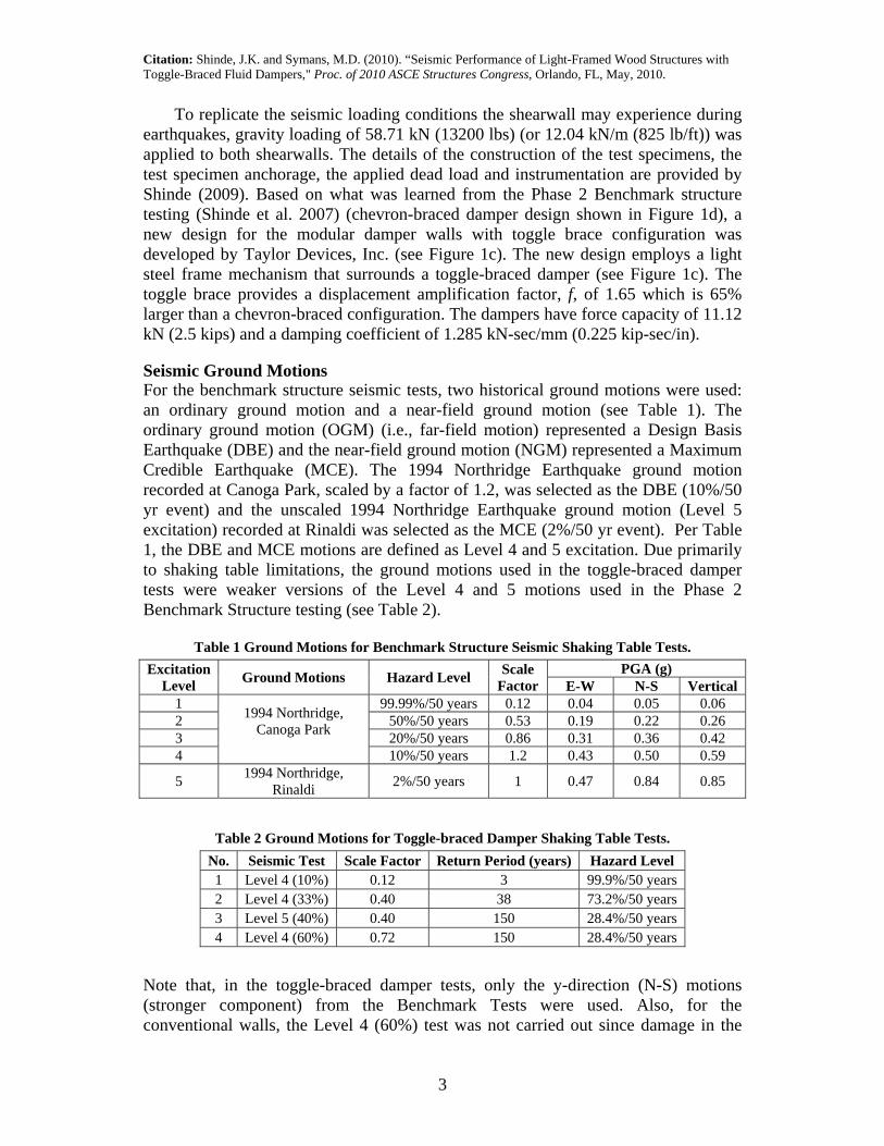
Acceleration Response Figure 4a and 4b shows the acceleration response for Level 4 (33%) excitation and Level 5 (40%) excitation, respectively. Note that the acceleration was significantly increased in the case of the retrofitted test specimen as compared to the conventional test specimen, especially beyond the time corresponding to the peak response. The
Citation: Shinde, J.K. and Symans, M.D. (2010). “Seismic Performance of Light-Framed Wood Structures with Toggle-Braced Fluid Dampers," Proc. of 2010 ASCE Structures Congress, Orlando, FL, May, 2010.
7
increase can be attributed to the higher natural frequency of the retrofitted specimen (see Table 4), due both to increased inherent stiffness of the retrofitted specimen and the reduction in damage that consequently minimizes the progressive reduction in stiffness. Since the peak acceleration is related to non-structural and contents damage, reduction of this quantity is desirable. For the retrofitted test specimen, the contribution of the toggle-braced assembly to the total structural stiffness was about 32%. If this contribution were significantly lower (e.g., if the dampers were installed within a full size building rather than in single shear wall components), a peak acceleration reduction on the order of 40% (based on numerical simulations of a two-story woodframed building) can be expected in woodframed structures retrofitted with fluid viscous dampers (Shinde et al. 2008).
(a) (b) Figure 4 Comparison of Experimental Acceleration: (a) Level 4 (33%) and (b) Level 5 (40%)
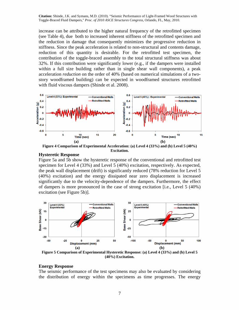
Excitation. Hysteretic Response Figure 5a and 5b show the hysteretic response of the conventional and retrofitted test specimen for Level 4 (33%) and Level 5 (40%) excitation, respectively. As expected, the peak wall displacement (drift) is significantly reduced (78% reduction for Level 5 (40%) excitation) and the energy dissipated near zero displacement is increased significantly due to the velocity-dependence of the dampers. Furthermore, the effect of dampers is more pronounced in the case of strong excitation [i.e., Level 5 (40%) excitation (see Figure 5b)].
(a) (b) Figure 5 Comparison of Experimental Hysteretic Response: (a) Level 4 (33%) and (b) Level 5
(40%) Excitation.
Energy Response The seismic performance of the test specimens may also be evaluated by considering the distribution of energy within the specimens as time progresses. The energy
Citation: Shinde, J.K. and Symans, M.D. (2010). “Seismic Performance of Light-Framed Wood Structures with Toggle-Braced Fluid Dampers," Proc. of 2010 ASCE Structures Congress, Orlando, FL, May, 2010.
8
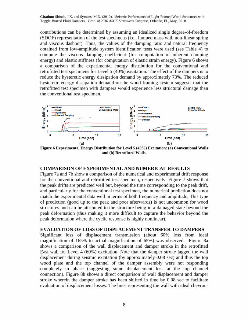
contributions can be determined by assuming an idealized single degree-of-freedom (SDOF) representation of the test specimens (i.e., lumped mass with non-linear spring and viscous dashpot). Thus, the values of the damping ratio and natural frequency obtained from low-amplitude system identification tests were used (see Table 4) to compute the viscous damping coefficient (for computation of inherent damping energy) and elastic stiffness (for computation of elastic strain energy). Figure 6 shows a comparison of the experimental energy distribution for the conventional and retrofitted test specimens for Level 5 (40%) excitation. The effect of the dampers is to reduce the hysteretic energy dissipation demand by approximately 73%. The reduced hysteretic energy dissipation demand on the wood framing system suggests that the retrofitted test specimen with dampers would experience less structural damage than the conventional test specimen.
(a) (b) Figure 6 Experimental Energy Distribution for Level 5 (40%) Excitation: (a) Conventional Walls
and (b) Retrofitted Walls.
COMPARISON OF EXPERIMENTAL AND NUMERICAL RESULTS Figure 7a and 7b show a comparison of the numerical and experimental drift response for the conventional and retrofitted test specimen, respectively. Figure 7 shows that the peak drifts are predicted well but, beyond the time corresponding to the peak drift, and particularly for the conventional test specimen, the numerical prediction does not match the experimental data well in terms of both frequency and amplitude, This type of prediction (good up to the peak and poor afterwards) is not uncommon for wood structures and can be attributed to the structure being in a damaged state beyond the peak deformation (thus making it more difficult to capture the behavior beyond the peak deformation where the cyclic response is highly nonlinear). EVALUATION OF LOSS OF DISPLACEMENT TRANSFER TO DAMPERS Significant loss of displacement transmission (about 60% loss from ideal magnification of 165% to actual magnification of 65%) was observed. Figure 8a shows a comparison of the wall displacement and damper stroke in the retrofitted East wall for Level 4 (60%) excitation. Note that the damper stroke lagged the wall displacement during seismic excitation (by approximately 0.08 sec) and thus the top wood plate and the top channel of the damper assembly were not responding completely in phase (suggesting some displacement loss at the top channel connection). Figure 8b shows a direct comparison of wall displacement and damper stroke wherein the damper stroke has been shifted in time by 0.08 sec to facilitate evaluation of displacement losses. The lines representing the wall with ideal chevron-

Citation: Shinde, J.K. and Symans, M.D. (2010). “Seismic Performance of Light-Framed Wood Structures with Toggle-Braced Fluid Dampers," Proc. of 2010 ASCE Structures Congress, Orlando, FL, May, 2010.
9
braced configuration ( f = 1.0), ideal toggle-braced configuration ( f = 1.65), and actual toggle-braced configuration ( f = 0.65) are also shown in the figure. The actual displacement magnification factor ( f = 0.65) is calculated directly as the ratio of the maximum damper stroke to the maximum wall displacement.
(a) (b) Figure 7 Comparison of Numerical and Experimental Drift Response: (a) Conventional Walls
and (b) Retrofitted Walls.
(a) (b)
Figure 8 Level 4 (60%) Excitation: (a) Comparison of Wall and Damper Stroke Response and (b) Evaluation of Displacement Transmission Losses.
IBC 2006 provides an analytical expression (Equation 23-2) to predict the total deflection experienced by a shearwall during an earthquake by combining four types of deflection: bending, shear, nail slip, and anchorage slip. Using these expressions, shearwall deflection calculations were performed for the Level 4 (33%), Level 5 (40%), and Level 4 (60%) tests for the retrofitted walls (Shinde 2009). The percentage contribution of each deflection component was then used to determine the amount of deflection that was transferred to the damper and the amount that was lost within the shearwall. It is assumed that only 30% of the deflection due to nail slip will

Citation: Shinde, J.K. and Symans, M.D. (2010). “Seismic Performance of Light-Framed Wood Structures with Toggle-Braced Fluid Dampers," Proc. of 2010 ASCE Structures Congress, Orlando, FL, May, 2010.
10
be lost within the shearwall, leaving 70% to be transmitted in pure shear to the dampers. The 30% value was selected such that it will give reasonable contribution of losses within the shearwalls to the total displacement transmission loss observed (about 60%). Based on these assumptions, the total displacement loss within the shearwall was estimated to be within the range of 30 to 40%. The additional displacement loss observed (i.e., 20 to 30%) may be due to gaps in joints of the toggle-assembly, gaps created due to crushing of holes in wooden top plates due to bolt bearing stress, high aspect ratio of the toggle-braced damper assembly (relative to those that have been used/tested in the past), and gaps in the wall to damper assembly connections. Another important contributor to the additional displacement loss is the deformation (elongation or contraction) of the bracing members in the toggle-braced assembly (Huang 2004). Note that the magnification factor ( f ) of 1.65 was derived assuming small deformations with rigid brace members. Thus, losses due to elongation of the bracing members may be significant. Influence of Displacement Transmission Loss on Peak Drift Table 5 shows the influence of displacement transmission loss on peak drift. Note that the values in Table 5 were obtained by comparing the experimental results from the conventional test specimen with numerical simulation results from the retrofitted test specimen. It is apparent that there is a significant seismic performance improvement in the retrofitted test specimen as compared to the conventional test specimen even with 60% loss in displacement transmission. The reduction in peak drift is in fact good enough to recommend the tested configuration for practical implementation.
Table 5 Influence of Displacement Transmission Loss on Peak Drift. TEST SPECIMEN MODIFICATION TO REDUCE DISPLACEMENT TRANSMISSION LOSS Since the retrofitted test specimen was in good condition after the final shake table test, it was decided to perform one additional seismic test in which a simple modification was made to the test set-up in an effort to reduce the displacement transmission loss to the damper. The modification was made at the connection between the wood top plate and the top steel channel of the damper assembly. Specifically, from the inside of the shear walls, two steel shear plates (9.53 mm (3/8 in) thick) were welded to each top channel and screwed to the top plate (see Figure 9a), the intent of the shear plates being to more directly transfer shear forces from the wood top plate to the steel top channel and thus to reduce displacement transmission losses at that location. The effect of the modified design is shown in Figure 9b for the East wall of the test specimen for Level 4 (60%) excitation. The damper stroke is
Peak Drift Reduction
Level 4 (33%) Level 5 (40%)
Ideal Toggle-Braced Damper (f = 1.65) 86% 93%
Actual Toggle-Braced Damper (f = 0.65) 63% 78%
Actual / Ideal 0.73 0.84

Citation: Shinde, J.K. and Symans, M.D. (2010). “Seismic Performance of Light-Framed Wood Structures with Toggle-Braced Fluid Dampers," Proc. of 2010 ASCE Structures Congress, Orlando, FL, May, 2010.
11
significantly increased, particularly for small displacement response (see Figure 9b), as compared to the test specimen prior to addition of the shear plates (see Figure 8a). The increased damper stroke corresponds to a displacement magnification factor (f ) that is increased by about 10% (from 0.65 to 0.72) resulting in reduced hysteretic energy dissipation demand on the framing system and thus a peak drift reduction of about 10% (from 0.97% to 0.89%). Also note that the time lag between the damper stroke and wall displacement during seismic excitation was reduced by approximately 60% (compare Figure 9b and Figure 8a).
(a) (b)
Figure 9 (a) Close-Up View of Steel Shear Plates for Reducing Displacement Transmission Losses and (b) Effect of Modified Design on Performance of East Wall of Test Specimen for
Level 4 (60%) Excitation. CONCLUDING REMARKS The research presented herein demonstrated the feasibility of implementing modular damper walls within a full-scale shearwall which can be constructed off-site and delivered to the job site for “drop-in” installation. The seismic performance of the retrofitted walls with the toggle-braced assembly was significantly improved as compared to the conventional walls. Evaluation of loss of displacement transmission revealed that there are additional possible sources of displacement loss in woodframed structures (on the order of 30% to 40%) as compared to steel and concrete structures. Additionally, there will be losses within the damper assembly itself. These losses should be taken into consideration during the design process. ACKNOWLEDGEMENTS This work was supported by the National Science Foundation (NSF) under Grant No. CMMI-0529903. Any opinions, findings, and conclusions or recommendations expressed in this material are those of the author(s) and do not necessarily reflect the views of NSF. The fluid viscous dampers and toggle assembly used in the testing were manufactured and donated by Taylor Devices, Inc. of North Tonawanda, NY. Technical assistance provided by Mr. Douglas Taylor (President) and Mr. John Metzger (Engineering Manager) of Taylor Devices, Inc., including design of the toggle-braced damper assembly, is gratefully acknowledged. In addition, Mr. James Knoll, working under an NSF REU Supplement to Grant No. CMMI-0529903, provided assistance with evaluation of losses in the shearwall tests.

Citation: Shinde, J.K. and Symans, M.D. (2010). “Seismic Performance of Light-Framed Wood Structures with Toggle-Braced Fluid Dampers," Proc. of 2010 ASCE Structures Congress, Orlando, FL, May, 2010.
12
REFERENCES ASCE (2006). “Seismic Rehabilitation of Existing Buildings,” ASCE/SEI 41-06, American Society of
Civil Engineers, Reston, VA. Constantinou, M.C., Tsopelas, P., Hammel, W. and Sigaher, A.N. (2001). “Toggle-Brace-Damper
Seismic Energy Dissipation Systems,” Journal of Structural Engineering, 127(2), 105–112. Dutil, D.A. and Symans, M.D. (2004). “Experimental Investigation of Seismic Behavior of Light-
Framed Wood Shear Walls with Supplemental Energy Dissipation,” 13th World Conference on Earthquake Engrg., Vancouver, B.C., Canada.
Folz, B. and Filiatrault, A. (2004). “Seismic Analysis of Woodframe Structures. I: Model Formulation,” Journal of Structural Engineering, 130(9), 1353-1360.
Folz, B. and Filiatrault, A. (2001). “Cyclic Analysis of Wood Shear Walls,” Journal of Structural Engineering, 127(4), 433-441.
Hwang, J. S., Huang, Y. N., Hung, Y. H. and Hung, Y. H. (2005). “Analytical and Experimental Study of Toggle-Brace-Damper Systems,” Journal of Structural Engineering, 131(7), 1035-1043.
Huang, C.H. (2004). “Parametric Study for Motion Amplification Device with Viscous Damper,” 13th World Conference on Earthquake Engineering, Vancouver, B.C., Canada.
ICC (2006). “International Building Code,” International Code Council, Inc., Falls Church, VA. Kircher, C., Reitherman, R., Whitman, R. and Arnold, C. (1997). “Estimation of Earthquake Losses to
Buildings,” Earthquake Spectra, 13(4), 703–720. Porter, K.A., Beck, J.L., Seligson, H.A., Scawthorn ,C.R., Tobin, L.T., Young, R. and Boyd, T. (2001).
“Improving Loss Estimation for Woodframe Buildings”, CUREE Report No. W-18, Consortium of Universities for Research in Earthquake Engineering (CUREE), Richmond, CA.
Shinde, J.K. (2009). “Integration of Seismic Protection Systems in Performance-Based Seismic Design of Woodframed Structures,” Ph.D. Dissertation, Dept. of Civil and Environmental Engineering, Rensselaer Polytechnic Institute, Troy, NY.
Shinde, J.K., Symans, M.D., Liu, H. and van de Lindt, J.W. (2008). “Seismic Performance Assessment of Woodframed Structures with Energy Dissipation Systems,” Proc. of Eighteenth Conf. on Analysis and Computation held in Conjunction with ASCE/SEI Structures Congress 2008, Vancouver, Canada, April.
Shinde, J.K., Symans, M.D., van de Lindt, J.W. and Filiatrault, A. (2007). “Application of Seismic Protection Systems to Woodframed Buildings: Full-Scale Testing and Field Implementation,” Proc. of 5th Annual NEES Meeting, Snowbird, Utah, June.
Symans, M.D., Cofer, W.F. and Fridley, K.J. (2002). “Base Isolation and Supplemental Damping Systems for Seismic Protection of Wood Structures: Literature Review,” Earthquake Spectra, 18(3), 549-572.
Symans, M.D. and Constantinou, M.C. (1998). “Passive Fluid Viscous Damping Systems for Seismic Energy Dissipation,” J. of Earthquake Technology, 35(4), 185-206.