Embed Size (px)
Citation preview

SEISMIC-INDUCED FIRE ANALYSIS OF STEEL-CONCRETE COMPOSITE BEAM-TO-COLUMN JOINTS: WELDED SOLUTIONS
Oreste S. Bursi
Department of Mechanical and Structural Engineering, University of Trento Trento, Italy
Fabio Ferrario Department of Mechanical and Structural Engineering, University of Trento
Trento, Italy [email protected]
Raffaele Pucinotti
Department of Mechanics and Materials, Mediterranean University of Reggio Calabria Reggio Calabria, Italy
[email protected] ABSTRACT A multi-objective design methodology dealing with seismic-induced fire on steel-concrete composite moment resisting frames endowed with concrete filled tubes (CFT) full strength joints is presented in this paper. In order to achieve these goals analytical and FE simulations including thermal analyses were carried out to design the proposed joints: this was followed by experimental tests under monotonic and cyclic loadings. Preliminary, seismic and fire analyses provided valuable information on the performance of moment resisting frames endowed with the chosen joint typology. A total of six specimens was designed and subjected to lateral loads. The specimens were subassemblages of interior beam-to-column joints connected by means of welded connections. Relevant experimental results are presented and commented. Furthermore, since the scope of the project was to promote joint typologies able to survive a seismic-induced fire, specimens were damaged by imposing monotonic loads equivalent to damage induced by seismic excitations, before being subjected to fire loadings. Thus, valuable information was obtained about the endurance of the proposed joint typology.
INTRODUCTION Major earthquakes in urban areas were often followed by significant conflagrations that were difficult to control and resulted in extensive damage to property. For instance in the 1995 Kobe earthquake, more than a few fires occurred in fire-resistant buildings (Kobe City Fire Dept., 1995). Also, various surveys revealed that many fire protection systems, e.g. sprinkler systems, were damaged by earthquakes and lost their function because of mechanical failure and/or deformation by earthquake motion (MFIAJ, 1995). As a result: i) seismic-induced fire risk assessment methods able to evaluate fire risk according to size and type of buildings, installed

fire protection systems and intensity of input earthquake motion have been developed (Yashiro et al., 2000); ii) some studies on the evaluation of the fire resistance rating reduction of perimeter moment-resisting multi-storey frames owing to seismic loading were performed (Della Corte et al., 2003). At the beam-to-column joint level, different studies were carried out to evaluate the performance of steel joints under fire both from a numerical and a design viewpoint (Simoes da Silva et al., 2007, Simoes da Silva et al., 2005, Block et al., 2007). However, research seems to be very limited with respect to the performance of beam-to-column joints under fire loading, even though research is still active in the field of monotonic and cyclic loading (Gil and Bayo, 2007 and 2008, Salvatore et al., 2005). This context of limited information on beam-to-column steel-concrete composite joints under fire and seismic-induced fire, motivated the European Union-financed research project PRECIOUS, devoted to the development of fundamental data, design guidelines and prequalification of two types of fire-resistant composite beam-to-column joints: one endowed with partially reinforced-concrete-encased columns with I-section; one with CFT columns (Bursi et al., 2008). Because fire and earthquake are accidental actions and have been treated most often as independent events (EN Eurocode 1991-1-2, 2004, EN Eurocode 1998-1, 2005), the project fitted in a modern multi-objective performance-based design where fire safety is also considered on a structure characterized by stiffness deterioration and strength degradation owing to seismic actions. In detail: the intensity measures were defined by means of artificial accelerograms and natural fires; engineering indices were defined in terms of joint distortions, interstory drifts and time for fire resistance; damage measures owing to earthquake and fire were considered both at the joint and at the frame level taking into account the interaction between joints and members; decision variables were related to life safety (SEAOC, Vision 2000). The project achieved its objective through a balanced combination of analytical/numerical and experimental work. The present paper only concentrates on Type 2 joints, for which it is presented: i) both frame design and joint design for seismic and fire loadings; ii) the analysis of both mechanical and thermal behavior of this typology by means of experimental tests; iii) results from moment resisting frames endowed with the investigated joint solution under seismic loading.
DESIGN OF REFERENCE FRAMES UNDER EARTHQUAKE AND FIRE In order to obtain design actions on joints, two moment resisting frames were designed with the same structural typology but different slab systems. In the frame design, particular attention was paid to the layout of structural elements according to economic criteria and to their optimization both for vertical and lateral loads. The reference structures are depicted in Figure 1(a) to 1(c) and are made up of three moment resisting frames placed at the distance of 7.5 m each in the longitudinal direction; while they are braced in the transverse direction with an interstorey height of 3.5 m. Two different slab systems were considered: i) a concrete slab composed of electro-welded lattice girders as shown in Figure 2(a); ii) a composite steel-concrete slab with structural profiled steel sheeting as illustrated in Figure 2(b). All slabs were arranged in parallel to main frames. Steel beams and slabs were fully connected with full interaction by means of Nelson 19 mm (3/4 in.) stud connectors with an ultimate tensile strength fu=450 MPa. In both cases, composite beams were realized with S355 (A615 Grade 50) IPE400 steel profiles, while composite columns were realized with 457 mm (18 in.) circular steel tubes with 12 mm thickness. The seismic performance of typical frames was evaluated by means of nonlinear static pushover analysis. Afterwards, the fire design issue was considered and the structural fire performance of the complete frame was evaluated by means of the SAFIR software (Franssen, 2000). In this respect, several simulations were carried out on the frames depicted in Figure 1 to assess the seismic-induced fire performance of the aforementioned moment resisting frames. Along the line of Della Corte et al. (2003), the effect of the seismic loading applied prior to fire

loading was taken into account by imposing one loading-unloading cycle through identical horizontal forces applied at each floor. In addition to an initial imperfection, this loading cycle induced some plasticity in each frame. The impact of the earthquake on the fire resistance of the analysed frames appeared to be not so significant because failure occurred when a beam plastic mechanism formed in the long-span heated beams. Moreover, no global instability modes formed under fire loading with a fire exposure lower than 30 minutes in the majority of cases.
a) b) c)
Figure 1 – Geometric layout of reference structures: a) structure with slabs with prefabricated lattice girders; b) structure with slabs with profiled steel sheeting; c) frame elevation
mesh Ø 6 / 20x200
880
5180
2100
pos.B 3+3 Ø 12
720
560
pos.C 8 Ø 16 / 200
pos.A 5 Ø 12 / 100
400160
5080
2000
1400150
pos.A 5 Ø 12 / 100pos.C 8 Ø 16 / 200
1900
1Ø8
HD
620
mes
hH
D 1
0/14
/8 h
=9,5
cm
1Ø10
1Ø10
pos.
Dpo
s.H
3Ø12
pos
.Bpo
s.E
1Ø10
pos.
D
1Ø10
pos.
H
mesh Ø 6 / 200x200
880
2100
2000
1900
pos.C 7 Ø 16 / 250pos.A 4 Ø 12 / 100
5180
pos.B 3+3 Ø 12
720
560
pos.C 7 Ø 16 / 250
pos.A 4 Ø 12 / 100
1500150300160
5080
HD
620
mes
h
3Ø12
3Ø
12
Figure 2 – Schematic view: a) solution with prefabricated lattice girders; b) solution with steel
sheeting. (Dimensions in mm)
The slabs composed by prefabricated lattice girders illustrated in Figure 2(a) were endowed with 3+3φ12 (3+3#4 in.) longitudinal rebars and 5+5φ12@100 mm (5+5#4@4 in.) plus 8+8φ16@200 mm (8+8#5@8 in.) transversal steel bars. A mesh φ6@200x200 mm (φ6@8x8 in.) completed the slab reinforcement. Conversely, the slab with profiled steel sheeting was endowed with 3+3φ12 (3+3#4 in.) rebars, 4+4φ12@100 mm (4+4#4@4 in.) and 7+7φ16@250 mm (7+7#5@10 in.) transversal steel bars as shown in Figure 2(b); a mesh φ6@200x200 mm (φ6@8x8 in.) was adopted. It should be recalled that longitudinal and transversal rebars are needed to activate strut and tie Mechanism 1 and 2 foreseen in EN Eurocode 1998-1 (2005); one couple of longitudinal rebars was designed to face damage owing to seismic loading. The rebar steel grade was S450B (A615 Grade 60) while the concrete class was C30/37 (4350 psi). Composite beams were of Class 2 (EN 1993-1-1,2005).
The concrete filled tubular (CFT) columns were S355 (A615 Grade 50) endowed with 8φ16 (8#5) longitudinal rebars and φ8@150 mm (φ8@6 in.) stirrups as illustrated in Figure 3. The steel grade was S450B (A615 Grade 60) with concrete class C30/37 (4350 psi). Due to circular CFTs, the seismic design of composite beam-to-column joints was conceived to provide both adequate overstrength and stiffness with respect to connected beams, thus forcing plastic
a) b)
1
5
9
13
17
2
6
10
14
18
3
7
11
15
19
4
8
12
16
20

hinges formation in adjacent beams (EN 1998-1, 2005). Basides that: joints were detailed by using the component method as illustrated in Figure 4a (EN 1993-1-8. 2005).
pos.D 8 Ø 16
pos.E Ø 8 / 15 cm
95
325135
50 2490
150150
150120
2670
9040
Figure 3 - Column stub and reinforcements capable of hosting a through-column web plate
a)
-1400-1200-1000-800-600-400-200
0-3-2.6-2.2-1.8-1.4-1-0.6-0.2
M [k
Nm
]
Rotation [rad]
Hogging Moment (Ozone)t=20°C t=15 min
b)
Figure 4 – (a) Interior Type 2 joint and mechanical model; (b) Moment-rotation relationship of a joint as a function of the time fire resistance
The following components were considered in the method: concrete slab in compression; upper horizontal plate in compression; vertical plate in bending and lower horizontal plate in tension, for sagging moment; reinforcing bars in tension, upper horizontal plate in tension; vertical plate in bending and lower horizontal plate in compression for hogging moment. Eurocode 3 (EN 1993-1-8, 2005) does not provides formulas for some components, specially for tubes, thus, the concrete slab in compression and the upper horizontal plate in tension were characterized by means of FE models set with ABAQUS (Hibbitt et al., 2000), as illustrated in Figure 5 and 6, respectively.
a)
θ=45°
b)
Figure 5 – Strut and tie mechanisms assumed in the slab: a) Mechanism 2; b) Mechanism 1
The effective width b of plates was approximately assumed to be half of the total plate width. In the application of the component method the composite column was assumed to be infinitely rigid. Beam-to-column joints were rigid full-strength joints with respect to adjacent beams satisfying the condition that , ,j pl RdM was at least 1.3 RdplbM ,, (EN 1998-1, 2005). Moreover, full groove and fillet welds were used. In detail, fillet welds satisfied the relationship:
1.1d ov fyR Rγ≥ ⋅ ⋅ (1)
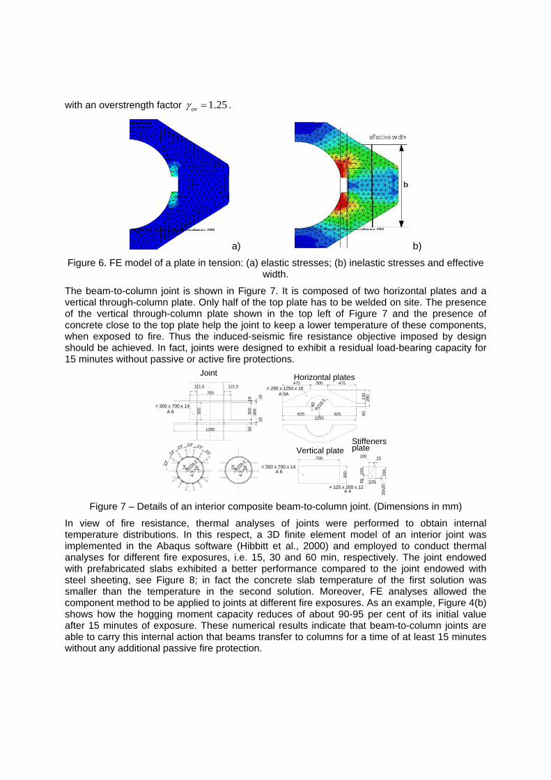
with an overstrength factor 1.25ovγ = .
a) b)
Figure 6. FE model of a plate in tension: (a) elastic stresses; (b) inelastic stresses and effective width.
The beam-to-column joint is shown in Figure 7. It is composed of two horizontal plates and a vertical through-column plate. Only half of the top plate has to be welded on site. The presence of the vertical through-column plate shown in the top left of Figure 7 and the presence of concrete close to the top plate help the joint to keep a lower temperature of these components, when exposed to fire. Thus the induced-seismic fire resistance objective imposed by design should be achieved. In fact, joints were designed to exhibit a residual load-bearing capacity for 15 minutes without passive or active fire protections.
230
60
475 300 475
625 6251250
40R22
8,5
290
= 290 x 1250 x 16A 5A
Horizontal plates
Vertical plate
300
700
= 300 x 700 x 14A 6
1250
700
A 6= 300 x 700 x 14
121,5121,5
300
369
1616
300
1950
Joint
R228,5
4,3
14 18
23°
23° 23° 23° 23°
33°
1814
4,3R22
8,5
Stiffeners
20x2
020
0
150
50
100 25
125= 125 x 200 x 12
A 4
plate
Figure 7 – Details of an interior composite beam-to-column joint. (Dimensions in mm)
In view of fire resistance, thermal analyses of joints were performed to obtain internal temperature distributions. In this respect, a 3D finite element model of an interior joint was implemented in the Abaqus software (Hibbitt et al., 2000) and employed to conduct thermal analyses for different fire exposures, i.e. 15, 30 and 60 min, respectively. The joint endowed with prefabricated slabs exhibited a better performance compared to the joint endowed with steel sheeting, see Figure 8; in fact the concrete slab temperature of the first solution was smaller than the temperature in the second solution. Moreover, FE analyses allowed the component method to be applied to joints at different fire exposures. As an example, Figure 4(b) shows how the hogging moment capacity reduces of about 90-95 per cent of its initial value after 15 minutes of exposure. These numerical results indicate that beam-to-column joints are able to carry this internal action that beams transfer to columns for a time of at least 15 minutes without any additional passive fire protection.

TEST PROGRAM The experimental programme covered the execution of six seismic tests and six fire tests on full-scale substructures representing interior welded beam-to-column joints. Seismic tests were carried out at the University of Trento, Italy, considering both cyclic and monotonic loadings. Fire tests were conducted at the Building Research Establishment, UK, with asymmetric loading on joints to simulate adjacent primary beams of different lengths.
a) b)
Figure 8 - FE model and temperature distribution for an interior joint endowed with: a) prefabricated lattice girder slabs b) profiled steel sheeting slabs.
Table 1 reports the joint specimens subjected to cyclic and monotonic loading up to collapse. Specimens 2-5 were endowed with horizontal Nelson stud connectors welded around the column, see Figure 7, to increase the friction level between the concrete slab and the composite column, thus favouring the Mechanism 2 idealized in Figure 5b. Specimen were tested according to the ECCS stepwise increasing amplitude loading protocol, modified with the SAC procedure (ECCS 1986, SAC 1997). In detail, it was imposed a yield displacement ey= 0.005h = 17.5 mm, where h represents the storey height.
Table 2 reports the test nomenclature of four interior specimens subjected to fire tests. In particular before fire testing, two specimens T21 and T24 were pre-damaged to simulate damage caused by an earthquake, i.e. by means of Type 1 spectrum compatible accelerograms at 0.4g pga (EN 1998-1, 2005). Conversely, Test T22 and T25 were not pre-damaged, to better appreciate seismic damage effects on fire resistance.
Table 1 – Specimens subjected to monotonic and cyclic tests
N. Label Test Protocol Type of Specimen
1 WJ-P1 Cyclic Specimens with electro-welded lattice girder slabs and no Nelson connectors around the column
2 WJ-P2 Cyclic Specimens with electro-welded lattice girder slabs and Nelson connectors around the column
3 WJ-PM Monotonic Specimens with electro-welded lattice girder slabs and no Nelson connectors around the column
4 WJ-S1 Cyclic Specimens with profiled steel sheeting slab and no Nelson connectors around the column
5 WJ-S2 Cyclic Specimens with profiled steel sheeting slab and Nelson connectors around the column
6 WJ-SM Monotonic Specimens with profiled Steel Sheeting slab and no Nelson connectors around the column
To accurately simulate damage owing to seismic events, non-linear dynamic time histories were performed by using the IDARC-2D program (Valles et al., 1996). Experimental data of joints

were used to define both hysteretic laws in IDARC-2D and damage domains according to the Chai & Romstad criterion (Chai et al., 1995).
Table 2 – Specimens subjected to fire tests
N. Label Test Method
Type of Specimen
1 T21 Fire Pre-damaged Specimen endowed with steel sheeting slabs
2 T22 Fire Undamaged Specimen endowed with steel sheeting slabs
3 T24 Fire Pre-damaged Specimen endowed with prefabricated lattice slabs
4 T25 Fire Undamaged Specimen endowed with prefabricated lattice slabs
The corresponding values of damage in joints provided by IDARC-2D simulations are gathered in Table 3 where average values for joints with prefabricated slab and steel sheeting slab are provided owing to the limited number of experimental data. The trend is evident: the damage in joints was limited and repairable.
Table 3 – Damage index for joints with prefabricated slabs and slabs with steel sheeting
Joint typology Damage index D Exterior joint 0.43 Interior joint 0.34
Subsequently, specific deformations were prescribed on joints through monotonic vertical loading to induce the damage identified in Table 3. Hence, specimens were loaded according to the fire load combination (EN 1991-1-2, 2004) and fire tests were undertaken. Typical beam-to-column joint specimens are illustrated in Figure 9. A welding procedure employed in laboratories was conceived to simulate on site welding, taking into account the Type of electrode employed, i.e. OERLIKON-ETC PH355 φ=3.25, with a pre-heating at 80°C.
CFT
Ø 4
57 x
12
A
A
IPE 400
Slab with electro-welded lattice girders
a)
A
150
A
IPE 400
CFT
Ø 4
57 x
12
Slab with profiled steel sheetings
b)Figure 9 - Beam-to-column joint specimens: a) slab with lattice girders; b) slab with sheetings
The experimental set-up employed for seismic tests is shown in Figure 10. A hydraulic actuator endowed with a capacity of ±1000 kN and a stroke ±250 mm were used. Different sensors were utilized: 5 inclinometers to measure rotations of joint and beams; 4 LVDTs to detect interface slip between steel beam and concrete slab; 2 LVDTs to measure joint deformations; 10 LVDTs and 4 Omega strain gauges to assess concrete slab deformations; 8 strain gauges to monitor axial deformations of rebars; 8 strain gauges to measure top and bottom plate deformations and flange strains; 2 load cell located in trusses to measure horizontal and vertical components of reaction forces; 1 digital transducer DT500 to detect top column displacements.

BOTTOM PLATE
TOP PLATE
BEAM
SLAB OMEGA STRAING GAUGELVDTs
STRAING GAUGESGOL
LL LL
LLLLL
SG
SG
SG
SGSG
SG SG
OOO
O
LVDTsINCLINOMETERS I
L
SG
SG
SG
SG
SG
SG
SG
SG
BEAMI I I I I L
LL LL
L
Figure 10 - Lateral view of the test set-up and instrumentation
TEST RESULTS AND ANALYSIS Seismic test results of beam-to-column joints Both the force-interstory drift and moment-rotation relationships of WJ-P1 and WJ-P2 specimens with electro-welded lattice slabs and without/with Nelson connectors around the column are illustrated in Figure 11 and 12, respectively. Plastic hinges developed in beams adjacent to joint and progressive deterioration of strength and stiffness was associated with beam flange buckling. Failure was due to beam flange cracking. A reader can observe that specimens exhibited a similar behaviour and beams developed plastic rotations greater than 25 mrad required by Eurocode 8 (EN 1998-1, 2005) for moment resisting frames of Medium ductility class.
Specimen WJ-P1
-1000-800-600-400-200
0200400600800
1000
-8 -6 -4 -2 0 2 4 6 8
Interstory Drift [%]
Forc
e [k
N]
Specimen WJ-P1
-800-600-400-200
0200400600800
1000
-80 -60 -40 -20 0 20 40 60 80
φ [mrad]
M [k
Nm
m]
Left HingeRight Hinge
Figure 11 – Specimen WJ-P1: Force-Displacement and Moment-Rotation relationship
Specimen WJ-P2
-1000
-500
0
500
1000
-8 -6 -4 -2 0 2 4 6 8
Interstory Drift [%]
Forc
e [k
N]
Specimen WJ-P2
-800-600-400-200
0200400600800
1000
-80 -60 -40 -20 0 20 40 60 80
φ [mrad]
M [k
Nm
m]
Left HingeRight Hinge
Figure 12 – Specimen WJ-P2: Force-Displacement and Moment-Rotation relationship
Similar results were obtained for specimens WJ-S1 and WJ-S2 endowed with slabs with profiled steel sheeting and without/with Nelson connectors around the column, respectively. Experimental results are shown in Figure 13 and Figure 14, respectively. Favourable results can

be observed. Nonetheless differently from previous cases, both in beams and joints, the neutral axis was located in the beam web for sagging moment owing to the greater damage imparted by lateral loads to the slabs endowed with steel sheeting.
Specimen WJ-S1
-1000-800-600-400-200
0200400600800
1000
-8 -6 -4 -2 0 2 4 6 8
Interstory Drift [%]
Forc
e [k
N]
Specimen WJ-S1
-800-600-400-200
0200400600800
1000
-80 -60 -40 -20 0 20 40 60 80
φ [mrad]
M [k
Nm
]
Left HingeRight Hinge
Figure 13 – Specimen WJ-S1: Force-Displacement and Moment-Rotation relationships
Specimen WJ-S2
-1000-800-600-400-200
0200400600800
1000
-8 -6 -4 -2 0 2 4 6 8
Interstory Drift [%]
Forc
e [k
N]
Specimen WJ-S2
-800-600-400-200
0200400600800
1000
-80 -60 -40 -20 0 20 40 60 80
φ [mrad]
M [k
Nm
]
Left HingeRight Hinge
Figure 14 - Specimen WJ-S2: Force-Displacement and Moment-Rotation relationships
Monotonic test results for the specimen WJ-PM endowed with prefabricated slabs with electro-welded lattice girders without Nelson connectors welded around the columns are plotted in Figure 15. Similar results were obtained for the specimen WJ-SM slab endowed with slabs with profiled steel sheeting (Bursi et al., 2008). The electro-welded lattice slabs of WJ-PM exhibited less damage owing a most favourable composite action in the plastic hinge beam section.
Specimen WJ-PM
0
500
1000
0 2 4 6 8 10 12 14 16Interstory Drift [%]
Forc
e [k
N]
Specimen WJ-PM
-1000
-600
-200
200
600
1000
-160 -120 -80 -40 0 40 80 120 160
φ [mrad]
M [k
Nm
]
Right Plastic Hinge
Left Plastic Hinge
Figure 15 - Specimen WJ-PM: Force-Displacement and Moment-Rotation curves
Fire test results of beam-to-column joints Both pre-damaged and undamaged specimens were subjected to fire loading, see Table 2, and some results are presented herein. The temperature vs. time curve imposed to the specimens T21-T22 and T24-T25 is shown in Figure 16(a) and (b), respectively. Specimens T21 and T22 with profiled steel sheeting slabs exhibited failure owing to an excessive rate of deflection at approximately 40 minutes. The test on specimen T21 terminated after approximately 34 minutes owing to runaway deflection. Following the fire test, the profiled steel sheeting separated from the slab; then the slab cracked both along the surface and through the depth with extensive buckling at one hour both of the lower flange and the web of the adjacent east beam, as shown

in Figure 17. T24 and T25 specimens endowed with prefabricated slabs endured one hour of fire; however, in both cases specimens were very close to failure as indicated, in Figure 16b, by an increasing rate of deflections towards the end of the test.
T21 vs. T22
-900
-450
0
450
900
15 30 45 60
Time [min]D
efle
ctio
n [m
m]
-75
-50
-25
0
25
50
75
T21 TemperatureT22 TemperatureT21 West Deflec.T22 West Deflec.T21 East Deflec.T22 East Deflec.
Tem
pera
ture
[°C
]
a)
T24 vs. T25
-900
-450
0
450
900
15 30 45 60 75 90
Time [min]
Def
lect
ion
[mm
]
-75
-50
-25
0
25
50
75
T24 TemperatureT25 TemperatureT24 West Deflec.T25 West Deflec.T24 East Deflec.T25 East Deflec.
Tem
pera
ture
[°C
]
b) Figure 16 – Performance of damaged (T21/T24) and undamaged (T22/T25) specimens.
a) b) Figure 17 – Specimen T21: a) Surface cracking of the slab; b) Local buckling of east beam
However, at this stage, there was no permanent deformation and no sign of any significant damage from fire tests. Hence, it can be underlined that: i) there was no noticeable difference in the fire performance between pre-damaged and undamaged specimens both with precast and steel sheeting slabs; this result is in agreement with damage values reported in Table 3 and with the inherent safety of composite joints (EN 1998-1, 2005; Bursi et al., 2008); ii) precast slabs performed better also in fire tests than the corresponding specimens with steel sheeting at a fire exposure in excess of the 15 minutes required; iii) all specimens exhibited favourable seismic properties by performing in a ductile manner also under fire loading. Supplementary moment resisting frame analyses At the frame level, several simulations were performed to assess both the seismic and fire behaviour of moment resisting frames endowed with the proposed joint both with steel sheeting and prefabricated slabs (Bursi et al., 2008). In detail, specimens subjected to cyclic loadings developed plastic rotations greater than 25 mrad, thus being adequate for moment resisting frames of Medium ductility class (EN 1998-1, 2005). Along the line of the Aribert et al (2006) work, incremental dynamic analyses were performed on the prototype frames depicted in Figure 1, in order to find some correlation between required plastic rotations for high ductility moment frames, i.e. about 35 mrad, interstorey drifts and the demand in p.g.a. It is found that by using artificial accelerograms compatible with Type 1 Eurocode 8 spectrum (EN 1998-1, 2005), interstory drifts between 3.41÷5.80 per cent developed with p.g.a. ranging between 1.40÷1.92g. For brevity, some results provided by these analyses for joints endowed with Nelson studs around the columns are gathered in Table 4 where large p.g.a. values are evident. Moreover, it was shown that energy dissipating mechanisms within frames endowed with the examined joints relied on the formation of plastic hinges at beam ends and that a behaviour factor of about

4 was estimated, thus allowing to adopt the proposed joints for Ductility Class M moment frames.
Table 4 – Seismic demands and drifts for plastic joint rotations from frame analyses
Specimens endowed with electro-welded lattice slabs and with column's Nelson studs Time History pga (g) Plastic Joint Rotation (mrad) Location in Fig.1c Interstorey Drift (%)
Accelerogram 1 1.92 26.1 10 5.80 Accelerogram 2 1.80 26.2 6 4.55 Accelerogram 3 1.50 26.7 2 4.19
Specimens endowed with steel sheeting slabs and with column's Nelson studs Time History pga (g) Plastic Joint Rotation (mrad) Location in Fig.1c Interstorey Drift (%)
Accelerogram 1 1.72 23.0 7 5.36 Accelerogram 2 1.60 29.4 4 3.68 Accelerogram 3 1.40 26.1 1 3.98
CONCLUSIONS A multi-objective design methodology dealing with seismic-induced fire actions on steel-concrete composite moment resisting frames endowed with full strength joints using concrete filled tubes has been presented in this paper. Instead of a traditional single-objective design, where fire safety and seismic safety are achieved independently and the sequence of seismic and fire loadings are not accounted for, in the proposed multi-objective design developed by means of mechanical resistance of members and joints, it has been guaranteed: i) seismic safety with regard to accidental actions; ii) fire safety with regard to accidental actions; iii) fire safety for at least 15 min fire exposure on a structure characterised by stiffness deterioration and strength degradation owing to an earthquake. As a result, the fire design applied to a structure with reduced capacity owing to seismic actions has provided structural, seismic and fire safety as required, but also structural and fire safety and structural and seismic safety, respectively. These objective were achieved through a balanced combination of analytical/numerical and experimental works.
ACKNOWLEDGMENTS The writers are grateful to the European Union for financial support under the project PRECIOUS-RFS-CR-03034 and to the partners as well. Nonetheless, conclusions of this paper are those of the authors and not of the sponsor agency. REFERENCES Aribert J.M., Ciutina A.L., Dubina D., 2006, “Seismic response of composite structures including actual behaviour of beam-to- column joints”, in Composite construction in steel and concrete V, Leon and Lange ed. South Africa. ASCE, 708-717. Block F.M., Burgess I.W., Davison J. B., Plank R. J. 2007 The development of a component-based connection element for endplate connections in fire. Fire Safety Journal 42. 498–506. Bursi O.S., et al. Editors, Final Report PRECIOUS Project Contr. N. RFSCR-03034, 2008. Prefabricated Composite Beam-to-Concrete Filled Tube or Partially Reinforced-Concrete-Encased Column Connections for Severe Seismic and Fire Loadings. Chai Y.H., Romstad K.M., Bird S.M. 1995, “Energy-based linear damage model for high-intensity seismic loading”, Journal of Structural Engineering, ASCE, 121(5), 857-864.
Della Corte G., Landolfo R., Mazzolani F.M. 2003, “Post-earthquake fire resistance of moment resisting steel frames”, Fire Safety Journal, 38, 593-612. ECCS. 1986. Recommended Testing Procedure for Assessing the Behaviour of Structural Steel Elements under Cyclic Loads. Publication n° 45; EN 1991-1-2. 2004. “Eurocode 1: Actions on Structures. Part 1-2 : General Actions – Actions on structures exposed to fire”; EN 1993-1-1. 2005. “Eurocode 3: Design of steel structures. Part 1-1: General rules and rules for buildings; EN 1993-1-2. 2005. “Eurocode 3: Design of steel structures. Part 1-2: General rules - Structural fire design”; EN 1993-1-8. 2005. “Eurocode 3: Design of steel structures - Part 1-8: Design of joints”; EN 1994-1-2. 2005. “Eurocode 4: Design of composite steel and concrete structures - Part 1.2: General rules – Structural fire design”; EN 1998-1. 2005. “Eurocode 8: Design of structures for earthquake resistance - Part 1: General rules, seismic actions and rules for buildings”; Franssen J.-M. 2000. “SAFIR; Non linear software for fire design”. Univ. of Liege; Gil B., Bayo E. 2008. An alternative design for internal and external semi-rigid composite joints. Part I: Experimental research Engineering Structures 30. 218–231 Gil B., Bayo E. 2008. An alternative design for internal and external semi-rigid composite joints. Part II: Finite element modeling and analytical studies. Engineering Structures 30. 232–246 Hibbitt, Karlsson and Sorensen 2000. “ABAQUS User’s manuals”. 1080 Main Street, Pawtucket, R.I. 02860; Kobe City Fire Department 1995 Investigation report on damages fire protection systems caused by the Hanshin-Awaji earthquake in Kobe. SAC 1997, Protocol for Fabrication, Inspection, Testing, and Documentation of Beam-Column Connection Tests and Other Experimental Specimens, report n. SAC /BD-97/02; Salvatore W, Bursi OS, Lucchesi D. 2005. Design, testing and analysis of high ductile partial-strength steel–concrete composite beam-to-column joints. Computers & Structures; 83 (28–30):2334–52. Santiago, A, Simões da Silva L, Vila Real P, Milan Veljkovic. 2007. Numerical study of a steel sub-frame in fire. Computers and Structures. (submitted). SEAOC - Structural Engineers Association of California. 1995. Performance Based Seismic Engineering of Buildings, Vision 2000 Committee, 2 vols. Sacramento, CA. Simões da Silva, L., Santiago, A., Moore, D. e Vila Real, P. 2005. Behaviour of steel joints and fire loading. Int. J. of Steel and Composite Structures 5(6), pp. 485-513 (2005). The Marine and Fire Insurance Association of Japan (MFIAJ) 1995. Study report on reliability of fire protection systems at an earthquake, 1995. Valles R.E., Reinhorn A.M., Kunnath S.K., Li C., Madan A. 1996, IDARC2D Version 4.0: A Program for the Inelastic Damage Analysis of Buildings, Tech. Report NCEER-96-0010, 1-8. Yashiro, Y., Ebihara, M. and Notake, H., 2000, Fire safety Design and Fire Risk Analysis Incorporating Staff Response in Consideration of Fire Progress Stage. 15th meeting of US-Japan Cooperative Program in Natural Resources by Int. Assoc. for Fire Safety Science.