Embed Size (px)
Citation preview

International Research Journal of Engineering and Technology (IRJET) e-ISSN: 2395 -0056
Volume: 03 Issue: 05 | May-2016 www.irjet.net p-ISSN: 2395-0072
© 2016, IRJET | Impact Factor value: 4.45 | ISO 9001:2008 Certified Journal | Page 2139
SEISMIC BEHAVIOUR OF RC FRAME WITH AND WITHOUT MASONRY
INFILL
K.Kalaipandian1, R.Amuthaselvakumar 2
1 Assistant Professor, Civil Department, SVCET, Virudhinagar, TN, India
2 Assistant Professor, Civil Department, SVCET, Virudhinagar, TN, India
---------------------------------------------------------------------***---------------------------------------------------------------------ABSTRACT: In the building construction, framed
structures are frequently used due to ease of construction
and rapid progress of work. Masonry infill panels have
been widely used as interior and exterior partition walls
for aesthetic reasons and functional needs. Generally
designers neglect these infill walls in as ‘non-structural’
and treat the frames as conventional reinforced concrete
frames. However, the presence of infill the frame alters the
overall behavior, especially when the structure is
subjected to later loads. The objective of this study was to
investigate the behavior of one-fifth scale reinforced
concrete frame with and without brick infill under quasi
static loading. In this investigation the performance of
M25 grade of concrete frame mix designed as per IS
method with two types of masonry in filled frames such as
reinforced concrete frames without masonry infill (Bare
frame), reinforced concrete frames with brick masonry
infill were cast and studied. The study discusses the
strength of the frame under ultimate lateral loads till
failure. Conclusions are made based on the experimental
investigations.
KEYWORDS: Seismic behaviour of RC Frame, frame with
and without masonry infill.
1. INTRODUCTION
Vibrations which disturb the earth’s surface caused by
waves generated inside the earth are termed as
earthquakes. It is said that earthquakes will not kill the
life of human but structures which are not constructed in
considering the earthquake forces do. At present a major
importance has given to earthquake resistant structures
in India for human safety. India is a sub-continent which
is having more than 60% area in earthquake prone zone.
A majority of buildings constructed in India are designed
based on consideration of permanent, semi-permanent,
movable loads. But earthquake is an occasional load
which leads to loss of human life but also disturbs social
conditions of India.
2. NEED FOR SEISMIC EVALUATION
It is known that damaging earthquakes are very
often followed by a series of aftershocks and sometimes
by other main shocks. Past earthquakes have shown that
when urban areas are hit by damaging earthquakes, a
significant percentage of structures attain light to
moderate damage. Moreover, it is known that structures
that sustained some damages prior to seismic event may
collapse during a succeeding event. Such unfortunate
events have claimed many lives. Therefore, these
structures impose a potential risk to human life,
economic assets and the environment. Thus, making
decisions regarding the post-earthquake functionality
and repair of the damaged structures is a critical part of
the post-earthquake recovery process. Also, from the
effects of significant earthquakes that has struck the
different parts of country, it is concluded that the seismic
risks in urban areas are increasing and are far from
socio-economically acceptable levels. Therefore, an
accurate estimation of the performance of structure
during an earthquake is crucial for estimating the actual
effects of that earthquake on the existing RC structures.

International Research Journal of Engineering and Technology (IRJET) e-ISSN: 2395 -0056
Volume: 03 Issue: 05 | May-2016 www.irjet.net p-ISSN: 2395-0072
© 2016, IRJET | Impact Factor value: 4.45 | ISO 9001:2008 Certified Journal | Page 2140
The vulnerability of the
structure can be assessed with a higher accuracy and
better informed decisions can be made on the possible
improvement of the seismic resistance of RC structures.
For example, the critical components of the structure
that are likely to sustain significant damages during
future earthquake ground motions may be identified.
Accordingly, the required immediate structural
interventions may be designed to reduce the
deformation demands on these components.
Subsequently, the overall behavior of the structure may
be improved to achieve a satisfactory overall seismic
performance during a future earthquake.
3. PRESENT INVESTIGATION
3.1 DIMENSIONAL AND DETAIL OF R.C FRAME
MODEL
One fifth scale model of single concrete frames
with a total height of 1.4m has been constructed. Each
storey height is 0.6 m. Plan of the reinforced concrete
frame model is shown in figure 1. Beams and columns
are of size 100 X 100 mm and 150 X 100 mm
respectively. The beam reinforcement consists of four
numbers of 8 mm diameter bars. Columns are reinforced
with four numbers of 10mm diameter bars. Lateral ties
in the columns and beams are 6 mm diameter two
legged stirrups at a spacing of 50 mm c/c at middle and
25 mm c/c at edge. The orientation and size of column is
kept same throughout the height of the structure. The
reinforcement has been fabricated conforming to the IS:
13920-1993. Material used are M 25 grade concrete and
Fe 415 steel.
Fig-1: Reinforcement Details of the Frame
Fig-2: Reinforcement Grill for the RC Frame
Fig-3: Closer View of Beam-Column

International Research Journal of Engineering and Technology (IRJET) e-ISSN: 2395 -0056
Volume: 03 Issue: 05 | May-2016 www.irjet.net p-ISSN: 2395-0072
© 2016, IRJET | Impact Factor value: 4.45 | ISO 9001:2008 Certified Journal | Page 2141
4. TEST SETUP
Figure 4 shows the test setup adopted for
testing all the frame specimens. The effectiveness of
instrumentation setup and the loading were checked in
the beginning by loading and unloading the frame with
small loads (of the order of 1.5 KN at the two load
points) till all the readings was repeatable. The two
frames were tested under uni-directional lateral loads in
a quasi-static pattern simulating seismic action. In the
experiments, the lateral load called base shear was
applied at the beam levels using screw jack and the
applied load was measured using proving ring. Since the
main purpose of the experiment was to observe the
frame’s behaviour under lateral loading, no vertical load
was applied on the specimens except for the self-weight
of frames and walls. Initially a base shear of 15 KN was
applied and the loading was progressively increased by
10 KN base shears in successive cycles until the
maximum load-carrying capacity of the specimen was
reached.
During the tests, storey displacements and the
lateral loads were monitored. After each cycle, new
initiated cracks and crack propagations were marked on
the specimens and failure mechanisms were observed. The
deflectometer readings for calculating the error due to
rigid body rotation of foundation block were also
recorded.
FIG – 5: Test setup for both frames
5. INVESTIGATION OF RC FRAME WITHOUT
INFILL
The frame was subjected to lateral loads in a
quasi-static pattern simulating seismic action. The
history of sequence of loading for the bare frame is
shown in Figure 6. The load carrying capacity of the
specimen was named as ultimate load. The ultimate load
of 39 KN was reached in the fifth cycle of loading. The
load-displacement response of the bare frame was
recorded as plotted in Figure 7. At the ultimate base
shear, the top-storey deflection was found to be 28.5
mm. The displacement due to rigid body rotation of the
footing and the foundation block were incorporated in
the calculation of net deflection.
International Research Journal of Engineering and Technology (IRJET) e-ISSN: 2395 -0056
Volume: 03 Issue: 05 | May-2016 www.irjet.net p-ISSN: 2395-0072
© 2016, IRJET | Impact Factor value: 4.45 | ISO 9001:2008 Certified Journal | Page 2142
0
5
10
15
20
25
30
35
40
0 2 4 6
BA
SE
SH
EA
R k
N
LOAD CYCLE
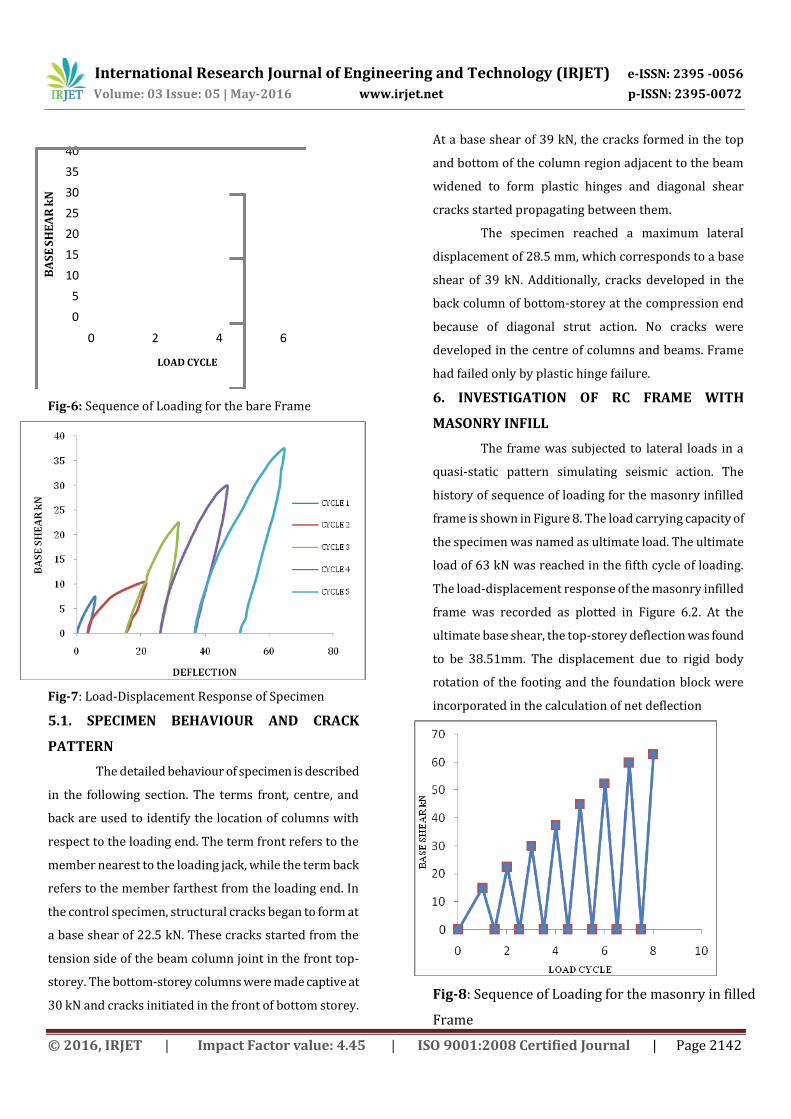
Fig-6: Sequence of Loading for the bare Frame
Fig-7: Load-Displacement Response of Specimen
5.1. SPECIMEN BEHAVIOUR AND CRACK
PATTERN
The detailed behaviour of specimen is described
in the following section. The terms front, centre, and
back are used to identify the location of columns with
respect to the loading end. The term front refers to the
member nearest to the loading jack, while the term back
refers to the member farthest from the loading end. In
the control specimen, structural cracks began to form at
a base shear of 22.5 kN. These cracks started from the
tension side of the beam column joint in the front top-
storey. The bottom-storey columns were made captive at
30 kN and cracks initiated in the front of bottom storey.
At a base shear of 39 kN, the cracks formed in the top
and bottom of the column region adjacent to the beam
widened to form plastic hinges and diagonal shear
cracks started propagating between them.
The specimen reached a maximum lateral
displacement of 28.5 mm, which corresponds to a base
shear of 39 kN. Additionally, cracks developed in the
back column of bottom-storey at the compression end
because of diagonal strut action. No cracks were
developed in the centre of columns and beams. Frame
had failed only by plastic hinge failure.
6. INVESTIGATION OF RC FRAME WITH
MASONRY INFILL
The frame was subjected to lateral loads in a
quasi-static pattern simulating seismic action. The
history of sequence of loading for the masonry infilled
frame is shown in Figure 8. The load carrying capacity of
the specimen was named as ultimate load. The ultimate
load of 63 kN was reached in the fifth cycle of loading.
The load-displacement response of the masonry infilled
frame was recorded as plotted in Figure 6.2. At the
ultimate base shear, the top-storey deflection was found
to be 38.51mm. The displacement due to rigid body
rotation of the footing and the foundation block were
incorporated in the calculation of net deflection
Fig-8: Sequence of Loading for the masonry in filled
Frame

International Research Journal of Engineering and Technology (IRJET) e-ISSN: 2395 -0056
Volume: 03 Issue: 05 | May-2016 www.irjet.net p-ISSN: 2395-0072
© 2016, IRJET | Impact Factor value: 4.45 | ISO 9001:2008 Certified Journal | Page 2143
0
10
20
30
40
50
60
70
0 20 40 60 80 100 120
Fig-9: Load-Displacement Response of Specimen
6.1 SPECIMEN BEHAVIOUR AND CRACK PATTERN
In the specimen, structural cracks began to form at a
base shear of 42 kN. These cracks started from the tension side
of the beam column joint in the front top-storey. The bottom-
storey columns were made captive at 48 kN and cracks initiated
in the front of bottom storey. At a base shear of 50 kN, the
cracks formed in the top and bottom of the column region
adjacent to the beam widened to form plastic hinges and
diagonal shear cracks started propagating between them.
Simultaneously separation of infill took place in the bottom-
storey at the leeward end in each bay. At 52.5 kN, a shear crack
appeared in the masonry infill exactly along the diagonal & the
specimen reached a maximum lateral displacement of 38.51
mm, which corresponds to a base shear of 63 kN. Additionally,
cracks developed in the back column of bottom-storey at the
compression end because of diagonal strut action of the infill.
7. RESULTS AND DISCUSSIONS
7.1 LATERAL DEFLECTION
The masonry infilled frame was subjected to 8 cycles of
loading and the ultimate load is reached in the 8th cycle. After
the 8th cycle there was a drastic reduction of load associated
with large drift values. The observed ultimate load of frame was
63 kN and the corresponding maximum lateral displacement
was 38.51 mm.
The bare frame was subjected to 5 cycles of loading and
the ultimate load is reached in the 5th cycle. After the 5th cycle
there was a drastic reduction of load associated with large drift
values. The observed ultimate load of frame was 39 kN and the
corresponding maximum lateral displacement was 28.5 mm.
7.2 STIFFNESS
The stiffness was calculated as the amount of base
shear required for causing unit deflection at the top-storey
level. The initial stiffness of the masonry in filled frame was
8.85kN/mm. In Figure 5.8, the stiffness was found to decrease
from 8.85 kN/mm during the second cycle to1.27 kN/mm
during the eighth cycle of loading.
The initial stiffness of the bare frame was 6.375
kN/mm. The stiffness was found to decrease from 6.375
kN/mm during the second cycle to 2.58kN/mm during the fifth
cycle of loading.
7.3 ENERGY DISSIPATION CAPACITY
The energy dissipation was determined by calculating the
areas inside the hysteretic load-displacement loops for each
cycle. The energy dissipation may be considered as a measure
of material damage to the specimen. The cumulative energy
dissipated was calculated as the sum of the energy dissipated
in consecutive cycles throughout the test.
7.4 First Crack Load of with and without Infill
The first cracks observed in the experimental results
of the bare frame model were compared with brick infill
frame model results as shown in the figure
Fig-10: First Crack Load of with and without Infill

International Research Journal of Engineering and Technology (IRJET) e-ISSN: 2395 -0056
Volume: 03 Issue: 05 | May-2016 www.irjet.net p-ISSN: 2395-0072
© 2016, IRJET | Impact Factor value: 4.45 | ISO 9001:2008 Certified Journal | Page 2144
7.5 Ultimate Load of with and without Infill
The ultimate load in the experimental results
of the bare frame model was compared with brick infill frame
model results as shown in the figure.11
Fig-11: Ultimate Load of with and without Infill
8. CONCLUSIONS
In the present experimental investigation to
understand the lateral load responses of two storied RC frame
with and without masonry infill Structure; a carefully designed
experimental setup was developed.
Based on the experiments, the following conclusions
can be drawn;
i) The ultimate failure pattern was by way of
development of typical X – type plastic hinges at beam-
column junctions and cracks are transferred through
the masonry infill from one beam to another.
ii) The salient results are lateral deflection, stiffness
degradation & Energy dissipation.
iii) It may also be concluded that this experimental setup
could be utilized for further experimental parameters
involving partial masonry in-fill.
9. REFERENCES
[1] IS 456:2000 Code of practice for Reinforced Concrete
design, BIS, New Delhi, India.
[2] IS: 1893(part1):2002, Criteria for earthquake resistant
design of structures, BIS, New Delhi, India.
[3] IS 13920:1993, code of practice for Ductile detailing of RC structures subjected to seismic forces, BIS, New Delhi, India [4] Park.R and Paulay.T, “Reinforced concrete structures”,