Embed Size (px)
Citation preview

International Research Journal of Engineering and Technology (IRJET) e-ISSN: 2395-0056
© 2018, IRJET | Impact Factor value: 6.171 | ISO 9001:2008 Certified Journal | Page 523
Seismic Behavior of Multi storey Building With and Without Floating
Veeresh hiremath1, Manasa veena2
1Assistant professor, Dept. of civil Engineering, RYMEC Ballari, Karnataka, India 2PG Student, department of civil engineering, RYMEC Ballari, Karnataka, India
---------------------------------------------------------------------***---------------------------------------------------------------------
Abstract - Modern multi-storey buildings are constructed with irregularities such as soft storey, vertical or plan irregularity, floating column and heavy loads. It is observed that most of the RC structures with such irregularities constructed are highly undesirable in seismically active areas from the results of past earthquake studies. These effects occurred due to various reasons, such as non-uniform distribution of mass, stiffness and strength. This study explains the seismic analysis of a multi-storey building with and without floating column constructed in seismically active areas observing its reactions to the external lateral forces exerted on the building in various seismic zones using the software ETABS v15. Thus highlighting the alternative measures involving in improvising the non-uniform distribution in the irregular building such as multi-storied building with floating column, and recommended the safer design of such building in seismically active areas considering the results observed from story drifts, story displacements and shear force comparing equivalent static, response spectrum and time history methods. KeyWords: Floating column, story drift, story displacement, Equivalent static, response spectrum, time history.
1. INTRODUCTION The columns are the vertical structural members which transfer the structural load coming from slabs and beam vertically to the ground. The vertical member which rest on a beam but doesn’t transfer the load to the foundation is known as floating column. It acts as a point load on the beam and the load transfers by these beams to the columns below it. The column may start off on the first or second or any other intermediate floor while resting on a beam. Usually columns rest on the foundation to transfer load from slabs and beams. But the floating column rests on the beam. This means that the beam which supports the column acts as a foundation. That beam is called as a transfer beam. This is widely used in high storied buildings for both commercial and residential purpose. . These buildings are considered to be safe under gravity loads and are designed only for gravity loads not for seismic loads. Hence these buildings may be unsafe in seismic prone areas. When these floating columns are employed in buildings in seismic prone areas, the entire earthquake of the system is shared by the column or the shear walls without considering any contribution from the floating columns.
2. MODELLING DETAILS 2.1 3m span 6bay 10 storey regular model (RM)
PLAN (M1)
ELEVATION
Volume: 05 Issue: 02 | Feb-2018 www.irjet.net p-ISSN: 2395-0072
column
International Research Journal of Engineering and Technology (IRJET) e-ISSN: 2395-0056
Volume: 05 Issue: 02 | Feb-2018 www.irjet.net p-ISSN: 2395-0072
© 2018, IRJET | Impact Factor value: 6.171 | ISO 9001:2008 Certified Journal | Page 524
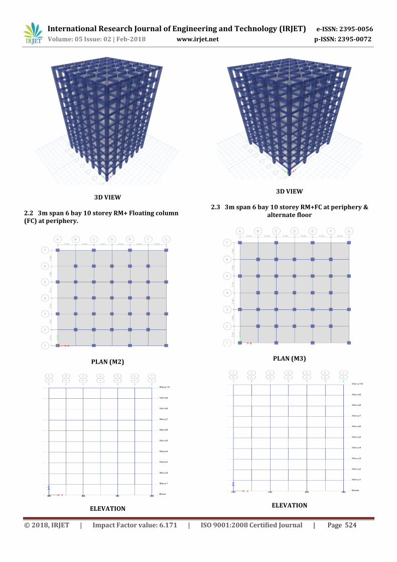
3D VIEW
2.2 3m span 6 bay 10 storey RM+ Floating column (FC) at periphery.
PLAN (M2)
ELEVATION
3D VIEW
2.3 3m span 6 bay 10 storey RM+FC at periphery & alternate floor
PLAN (M3)
ELEVATION

International Research Journal of Engineering and Technology (IRJET) e-ISSN: 2395-0056
Volume: 05 Issue: 02 | Feb-2018 www.irjet.net p-ISSN: 2395-0072
© 2018, IRJET | Impact Factor value: 6.171 | ISO 9001:2008 Certified Journal | Page 525
3D VIEW
2.4 4m span6bay 10 storey regular model.
PLAN (M4)
ELEVATION
3D VIEW
2.5 4m span 6 bay 10 storey RM+FC at periphery
Plan(M5)
ELEVATION

International Research Journal of Engineering and Technology (IRJET) e-ISSN: 2395-0056
Volume: 05 Issue: 02 | Feb-2018 www.irjet.net p-ISSN: 2395-0072
© 2018, IRJET | Impact Factor value: 6.171 | ISO 9001:2008 Certified Journal | Page 526
3D VIEW
2.6 4m span 6 bay 10 storey RM+FC at periphery & at alternate floor
PLAN(M6)
ELEVATION
3D VIEW
3. ANALYSIS OF SELECTED MODELS Dimensions of structural element:
1. Size of the column- 600×600mm.
2. Size of the beam-230×500mm
3. Thickness of slab-150mm
Specifications:
1. Earthquake Zone: 5
2. Soil Type: Medium Type II
3. Structure Type SMRF: R= 5
4. Importance Factor: I =1.5
Material properties:
1. M25 Weight/Unit Volume: 25 kN/m3
2. Modulus of elasticity E: 25000N/mm2
3. Poisson’s ratio, μ: 0.2
4. Co-efficient of thermal expansion,
A: 0.0000055°/c
5. Shear modulus, G: 10416.67N/mm2
6. Fck = 25N/mm²
7. Fy = 415 N/mm²
Loads:
1. LiveLoadonFloor=4kN/m²
2. Floor finish=1.5kN/m2

International Research Journal of Engineering and Technology (IRJET) e-ISSN: 2395-0056
Volume: 05 Issue: 02 | Feb-2018 www.irjet.net p-ISSN: 2395-0072
© 2018, IRJET | Impact Factor value: 6.171 | ISO 9001:2008 Certified Journal | Page 527
3. Live Load on Roof =3 kN/m²
4. Floor finish on roof=1.75kN/m²
Following models are analyzed using E-Tabs 2015 software. The results obtained are discussed further
4. EQUIVALENT STATIC ANALYSIS The equivalent static method is the simplest method of analysis and requires computational effort because , the forces depend on code based fundamental time period of structure with some empirical modifier. The designed base shear shall first computed as whole , the distributed along the height of the buildings based on simple formulas appropriate for buildings with regular distribution on mass and stiffness. This analysis is a technique of substituting the effect of dynamic loading of an expected earthquake by a distribution of static force laterally on the structure for design purposes. 4.1 EQSM-Storey displacement of M1,M2 & M3
Graph.4.1a:Storey displacement at x-direction (EQX)for M1,M2 & M3
Graph.4.1b:Storey displacement at Y-direction (EQY)for M1,M2 & M3
4.2 EQSM-interStorey drift of M1,M2 & M3
Graph.4.2a:Inter storey drift in X-direction (EQX) for M1,M2 & M3
Graph.4.2b:Inter storey drift in Y-direction (EQX) for M1,M2 & M3
TABLE.4.2: Storey Response: displacement in X-direction
Storey X-Dir X-Dir X-Dir M1 M2 M3 mm mm mm
10 41.6 44.9 45.1 9 39.8 42.8 43.2 8 37.0 39.7 40.0 7 33.3 35.7 36.1 6 28.8 31.0 31.1 5 23.9 25.8 25.9 4 18.5 20.1 20.0 3 13.0 14.3 14.3 2 7.6 8.5 8.2 1 2.7 3.2 3.1 0 0.0 0.0 0.0

International Research Journal of Engineering and Technology (IRJET) e-ISSN: 2395-0056
Volume: 05 Issue: 02 | Feb-2018 www.irjet.net p-ISSN: 2395-0072
© 2018, IRJET | Impact Factor value: 6.171 | ISO 9001:2008 Certified Journal | Page 528
4.3 EQSM-Storey shear of M1, M2 & M3
Graph.4.3a :Storey shear in X-direction (EQX) for M1,M2 & M3
Graph.4.3b:Storey shear in Y-direction (EQY) for M1,M2 & M3
5. RESPONSE SPECTRUM ANALYSIS
In response spectrum analysis sufficient number of modes must be considered in analysis such that total mass participation is at least 90%.Elastic Methods can predict elastic capacity of structure and indicate where the first yielding will occur, however they don‘t predict failure mechanism and account for the redistribution of forces that will take place as the yielding progresses. Moreover, force-based methods primarily provide life safety but they can‘t provide damage limitation and easy repair.
5.1 RSM-Storey displacement of M1, M2 & M3
Graph.5.1b:Storey displacement in Y-direction(RY) for M1,M2 & M3
5.2 RSM-Inter storey drift of M1, M2 & M3
Graph.5.2a:Inter storey drift in X-direction(RX) for M1,M2 & M3

International Research Journal of Engineering and Technology (IRJET) e-ISSN: 2395-0056
Volume: 05 Issue: 02 | Feb-2018 www.irjet.net p-ISSN: 2395-0072
© 2018, IRJET | Impact Factor value: 6.171 | ISO 9001:2008 Certified Journal | Page 529
Graph.5.2b:Inter storey drift in Y-direction(RY) for M1,M2 & M3
5.3 RSM-Storey Shear of M1, M2 & M3
Graph 5.3a:Storey shear in X-direction(RX) for M1,M2
& M3
Graph 5.3b:Storey shear in X-direction(RX) for M1,M2 & M3
6.TIME HISTORY ANALYSIS
A linear analysis of time history overcomes the disadvantages in the modal response spectrum analysis, where the non-linear time history analysis behavior is not involved. At discrete time this method calculating the response requires greater computational efforts. The relative signs of response qualities are preserved in the response histories is the one interesting advantage of such procedure. It is important among stress resultants when interaction effects are considered in design.
6.1 THM-Storey displacement of M4, M5 & M6
Graph.6.1a: Storey displacement in X-direction(TX) for
M4,M5 & M6
Graph.6.1b: Storey displacement in Y-direction(TY) for
M4,M5 & M6

International Research Journal of Engineering and Technology (IRJET) e-ISSN: 2395-0056
Volume: 05 Issue: 02 | Feb-2018 www.irjet.net p-ISSN: 2395-0072
© 2018, IRJET | Impact Factor value: 6.171 | ISO 9001:2008 Certified Journal | Page 530
6.2 THM-Storey drift of M4,M5,M6 for M4,M5,M6
Graph 6.2a:Inter storey drift in X-direction(TX) For M4,M5,M6
Graph 6.26:Inter storey drift in Y-direction(T Y) for
M4,M5,M6
7. CONCLUSION
In this project work, analysis of multi storey building with and without floating column is carried out with different analysis method. The seismic parameters like storey displacement, inter storey drift and storey shear are compared between all the selected models
From result it is observed that,
Displacements, in the structures varies with the size of the building as well as the bay size between the columns, as we observe M4, M5 & M6 with 4m bay size have more displacement than M1, M2&M3 with 3m bay size building. This shows increase in the bay size will directly effect on to the global stiffness of the buildings including floating column structural systems which results in higher lateral displacement.
We observed lesser displacements in M1,M4 regular structures when compared to M2,M5 aground floor level floating structural systems and higher displacements in M3,M6 alternate floor level floating structural systems.
This shows alternate floor floating column structural systems will effect much on global stiffness of the structure which results reduction in lateral load resisting capacity.
Inter storey drift,in the structures varies with the size of the building as well as the bay size between the columns, M4, M5 & M6 with 4m bay size between columns is found having higher drift compared to M1, M2& M3 with 3m bay size building .We observed lower inter storey drift in M1,M4 regular structures when compared to M2,M5 floor level floating structural systems and higher inter storey drift in M3,M6 alternate floor level floating structural systems. This shows that alternate floor floating column structural systems will effect much on global stiffness of the structure which results in soft storey effect thus result in higher drift.
Even though the stiffness and soft storey comes into effect here the mass distribution about the structure should be considered seriously structure with evenly distributed mass are less effected to drift than the structures unevenly architected or uneven mass distribution
REFERENCES
1. Maison Bruce F. and Neuss Carl F., “Dynamic analysis of a forty four storey building”, Journal of Structural Engineering, Vol. 111, No. 7, Page No:1559- 572,July, 1985.
2. Maison Bruce F. and Ventura Carlos E., “DYNAMIC ANALYSIS OF THIRTEEN STOREY BUILDING”, Journal of Structural Engineering, Vol. 117, No. 12, Page no: 3783-3803, 1991.
3. Arlekar Jaswant N, Jain Sudhir K. and Murty C.V.R, (1997), “Seismic Response of RC Frame Buildings with Soft First Storeys”. Proceedings of the CBRI Golden Jubilee Conference on Natural Hazards in Urban Habitat, 1997, New Delhi.
4. Mr. P.V. Prasad ,T.Raja Sekhar, “Study Of Behavior Of Seismic Analysis Of Multi Storied Building With And Without Floating Column”, Caribbean Journal of Science and Technology, 2014, Vol2, 697-710
5. Nikhil Bandwal1, Anant Pande2, “To Study Seismic Behavior of RC Building with Floating Columns‟‟, International journal of scientific engineering and technology and research. ISSN 2319-8885 Vol.03, Issue.08, May-2014, Pages: 1593-1596.
6. Pankaj Agarwal, Manish Shrikhande (2006), “Earthquake Resistant Design of Structures”, PHI private limited, New Delhi.

International Research Journal of Engineering and Technology (IRJET) e-ISSN: 2395-0056
Volume: 05 Issue: 02 | Feb-2018 www.irjet.net p-ISSN: 2395-0072
© 2018, IRJET | Impact Factor value: 6.171 | ISO 9001:2008 Certified Journal | Page 531
7. Awkar J. C. and Lui E.M, “Seismic analysis and response of multistory semirigid frames”, Journal of Engineering Structures, Volume 21, Issue 5, Page no: 425-442, 1997.
8. S.K. Duggal (2007), “Earthquake Resistant Design of Structures”, Oxford university press, YMCA library building Jai Singh road, New Delhi.
9. S.S.Bhavikatti, (2005) “Finite Element Analysis”,
New Age International (P) Ltd, Publishers, New Delhi.