Embed Size (px)
Citation preview
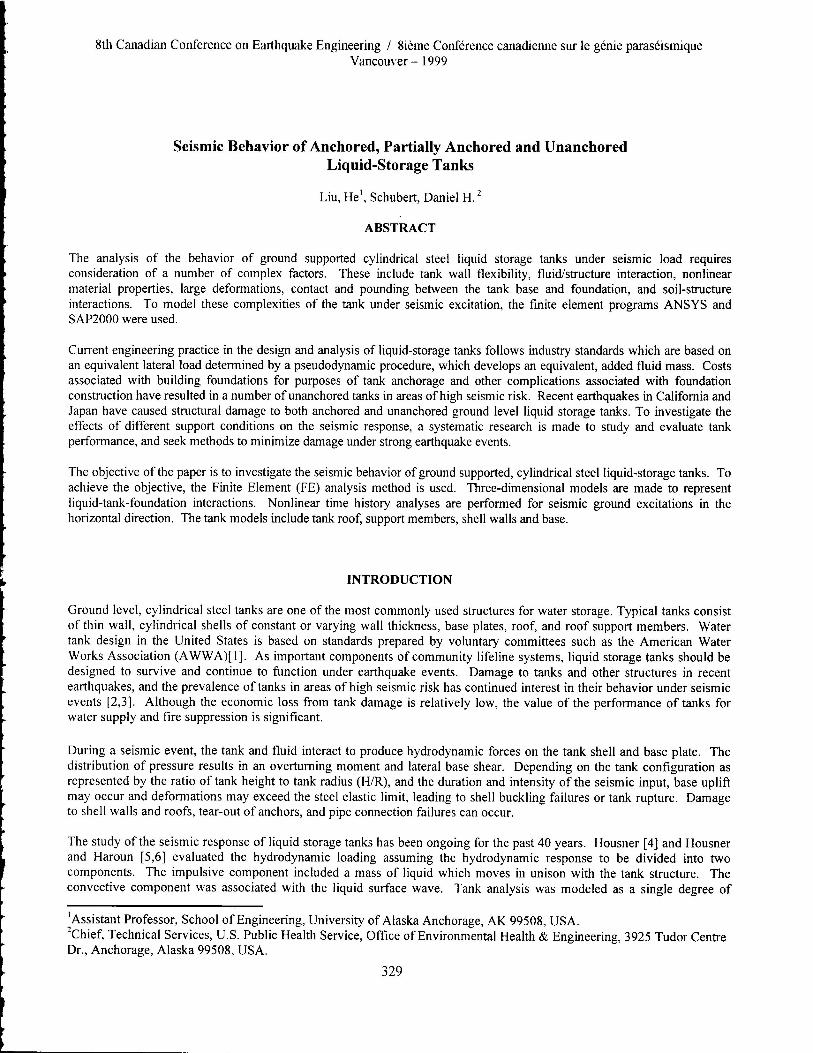
8th Canadian Conference on Earthquake Engineering / 8ieme Conference canadienne sur le genie paraseismique Vancouver — 1999
Seismic Behavior of Anchored, Partially Anchored and Unanchored Liquid-Storage Tanks
Liu, He', Schubert, Daniel H.'
ABSTRACT
The analysis of the behavior of ground supported cylindrical steel liquid storage tanks under seismic load requires consideration of a number of complex factors. These include tank wall flexibility, fluid/structure interaction, nonlinear material properties, large deformations, contact and pounding between the tank base and foundation, and soil-structure interactions. To model these complexities of the tank under seismic excitation, the finite element programs ANSYS and SAP2000 were used.
Current engineering practice in the design and analysis of liquid-storage tanks follows industry standards which are based on an equivalent lateral load determined by a pseudodynamic procedure, which develops an equivalent, added fluid mass. Costs associated with building foundations for purposes of tank anchorage and other complications associated with foundation construction have resulted in a number of unanchored tanks in areas of high seismic risk. Recent earthquakes in California and Japan have caused structural damage to both anchored and unanchored ground level liquid storage tanks. To investigate the effects of different support conditions on the seismic response, a systematic research is made to study and evaluate tank performance, and seek methods to minimize damage under strong earthquake events.
The objective of the paper is to investigate the seismic behavior of ground supported, cylindrical steel liquid-storage tanks. To achieve the objective, the Finite Element (FE) analysis method is used. Three-dimensional models are made to represent liquid-tank-foundation interactions. Nonlinear time history analyses are performed for seismic ground excitations in the horizontal direction. The tank models include tank roof, support members, shell walls and base.
INTRODUCTION
Ground level, cylindrical steel tanks are one of the most commonly used structures for water storage. Typical tanks consist of thin wall, cylindrical shells of constant or varying wall thickness, base plates, roof, and roof support members. Water tank design in the United States is based on standards prepared by voluntary committees such as the American Water Works Association (AWWA)[1]. As important components of community lifeline systems, liquid storage tanks should be designed to survive and continue to function under earthquake events. Damage to tanks and other structures in recent earthquakes, and the prevalence of tanks in areas of high seismic risk has continued interest in their behavior under seismic events [2,3]. Although the economic loss from tank damage is relatively low, the value of the performance of tanks for water supply and fire suppression is significant.
During a seismic event, the tank and fluid interact to produce hydrodynamic forces on the tank shell and base plate. The distribution of pressure results in an overturning moment and lateral base shear. Depending on the tank configuration as represented by the ratio of tank height to tank radius (H/R), and the duration and intensity of the seismic input, base uplift may occur and deformations may exceed the steel elastic limit, leading to shell buckling failures or tank rupture. Damage to shell walls and roofs, tear-out of anchors, and pipe connection failures can occur.
The study of the seismic response of liquid storage tanks has been ongoing for the past 40 years. Housner [4] and Housner and Haroun [5,6] evaluated the hydrodynamic loading assuming the hydrodynamic response to be divided into two components. The impulsive component included a mass of liquid which moves in unison with the tank structure. The convective component was associated with the liquid surface wave. Tank analysis was modeled as a single degree of
'Assistant Professor, School of Engineering, University of Alaska Anchorage, AK 99508, USA. 'Chief, Technical Services, U.S. Public Health Service, Office of Environmental Health & Engineering, 3925 Tudor Centre Dr., Anchorage, Alaska 99508, USA.
329
..... .0.,
I I
Figure 2 ANSYS FE Model
Figure 1 Dimensions and Coordinate System
freedom oscillator, with an equivalent mass located at different heights above the base. This allowed determination of the overturning moment and base shear, and still serves as the basis for the AWWA design standards.
A number of studies and research efforts have continued over the years, including experimental studies and theoretical developments to gain a greater understanding of tank behavior. Several methods are available to determine the dynamic response of liquid tanks. In previous work, the authors developed an approximate method by combining theoretical solutions with FE methods using the program SAP2000 [7]. The approach used in the current analysis, two different FE models are developed. The first model includes shell, beam and fluid finite elements using the ANSYS software. The ANSYS FE program incorporates many advanced features allowing greater emphasis on research and analysis capabilities. This program was used for both comparative purposes, and for greater evaluation into the complexities of tank behavior. The second modeling approach combines theoretically based analytical parameters for the contained fluid represented by convective and impulsive components, with the general purpose FE software, SAP2000. SAP2000 is a FE software developed primarily for structural analysis purposes, with only beam and shell elements available. Because of its analysis efficiency and design features, it is used by many civil engineers. Using this approximate method, the fluid-tank interaction analyses including effects of uplift of tank base by varying support conditions is developed.
ANCHORED TANK SUPPORT
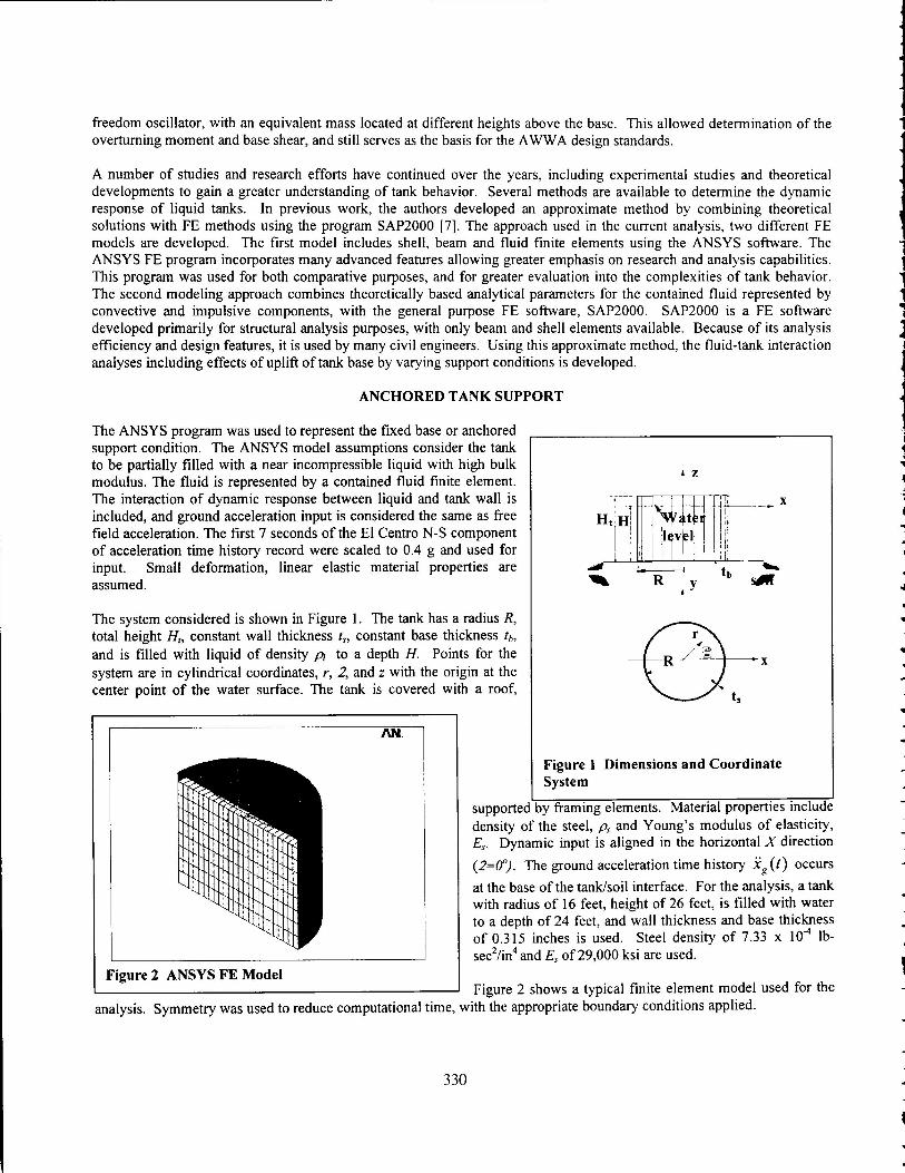
The ANSYS program was used to represent the fixed base or anchored support condition. The ANSYS model assumptions consider the tank to be partially filled with a near incompressible liquid with high bulk modulus. The fluid is represented by a contained fluid fmite element. The interaction of dynamic response between liquid and tank wall is included, and ground acceleration input is considered the same as free field acceleration. The first 7 seconds of the El Centro N-S component of acceleration time history record were scaled to 0.4 g and used for input. Small deformation, linear elastic material properties are assumed.
The system considered is shown in Figure 1. The tank has a radius R, total height H1, constant wall thickness ts, constant base thickness th, and is filled with liquid of density pi to a depth H. Points for the system are in cylindrical coordinates, r, 2, and z with the origin at the center point of the water surface. The tank is covered with a roof,
analysis.
Figure 2 shows a typical finite element model used for the Symmetry was used to reduce computational time, with the appropriate boundary conditions applied.
supported by framing elements. Material properties include density of the steel, p, and Young's modulus of elasticity, E. Dynamic input is aligned in the horizontal X direction
(2=0°). The ground acceleration time history .ig (t) occurs
at the base of the tank/soil interface. For the analysis, a tank with radius of 16 feet, height of 26 feet, is filled with water to a depth of 24 feet, and wall thickness and base thickness of 0.315 inches is used. Steel density of 7.33 x 10⁴ lb-sec2/in4 and E5 of 29,000 ksi are used.
330
1 r, i' r
r, i
A 1
I I 1
r ,
I
, 1 'I'
‘,II) I r i 01 li r ---
1
,-1 II I l A
I
'''h
(I' YI
I
Time (seconds)
8000
Mo
men
t (k
ip-f
t) 4000
0
-4000
-8000
-200 t
600 400
800
200 0
4
-400 _ -600 -800
Time (seconds)
Figure 3 Base Shear Time History — Anchored Tank
Figure 4 Overturning Moment Time History—Anchored Tank
Base S
hear
(kip
s)
:2 40
z- 20
0 E Left side
Rigt side al -20
0 5
V! in -40
Time (seconds)
Figure 5 Water Surface Time History
Distance, (ft)
Figure 6 Water Surface Profile Time History T=5.09s
Dis
pla
cem
ent,
(in
ch)
-20
-40
40
20
18 24 30
0 1 2 3 4 5
Time (seconds)
Figure 7 Pressure Time History — 3 ft. from Base
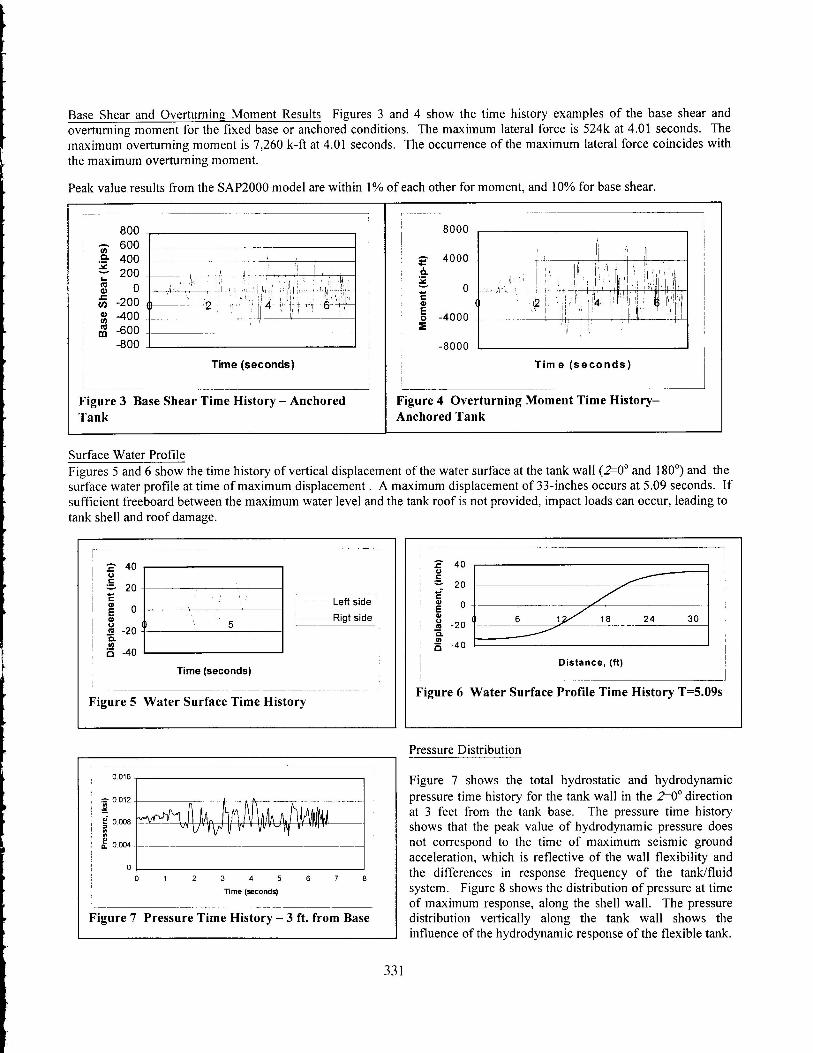
Base Shear and Overturning Moment Results Figures 3 and 4 show the time history examples of the base shear and overturning moment for the fixed base or anchored conditions. The maximum lateral force is 524k at 4.01 seconds. The maximum overturning moment is 7,260 k-ft at 4.01 seconds. The occurrence of the maximum lateral force coincides with the maximum overturning moment.
Peak value results from the SAP2000 model are within 1% of each other for moment, and 10% for base shear.
Surface Water Profile Figures 5 and 6 show the time history of vertical displacement of the water surface at the tank wall (2=0° and 180°) and the surface water profile at time of maximum displacement . A maximum displacement of 33-inches occurs at 5.09 seconds. If sufficient freeboard between the maximum water level and the tank roof is not provided, impact loads can occur, leading to tank shell and roof damage.
Pressure Distribution
Figure 7 shows the total hydrostatic and hydrodynamic pressure time history for the tank wall in the 2=0° direction at 3 feet from the tank base. The pressure time history shows that the peak value of hydrodynamic pressure does not correspond to the time of maximum seismic ground acceleration, which is reflective of the wall flexibility and the differences in response frequency of the tank/fluid system. Figure 8 shows the distribution of pressure at time of maximum response, along the shell wall. The pressure distribution vertically along the tank wall shows the influence of the hydrodynamic response of the flexible tank.
331

ro.
1145 -1,143 OL
U
Figure 9 Von Mises Stress Distribution at T=3.21 Seconds
0 000 0 DOS 0 010 0 015
Reece OW/
Figure 8 Pressure Distribution along Wall T=3.21 Seconds
Tank Wall Stresses
Figure 9 shows an example of the tank deformation and Von Mises stress at time of maximum deformation. Higher stresses are concentrated in the area near the base of the tank, which is consistent with observed deformation or "elephant's foot" phenomena. Similar distributions for vertical compressive, and hoop stress are also available.
PARTIALLY ANCHORED TANK SUPPORT
SAP2000 was used to model partially anchored or restraint in the horizontal direction and unanchored tank support conditions. The SAP2000 FE program is a general purpose, structural analysis and design program, commonly used in civil engineering practice. It incorporates linear and nonlinear features, and includes easy graphical user interfaces to allow rapid model development and load application. The impulsive component is considered coupled with the flexible tank and applied as a spatially varied added nodal mass, based on the first order terms.
The convective component is considered as an uncoupled time varied, applied dynamic load, which is distributed over the tank shell. To obtain this dynamic load, a separate dynamic analysis is conducted with the same seismic ground acceleration. Details of the assumptions and analysis methods are described in reference 7. An initial deformation of the tank structure due to dead and hydrostatic load was used as a starting condition for the dynamic analysis. The dynamic analysis method uses load dependent Ritz vectors. Figure 10 shows the typical model used. The same parameters and dimensions as in the ANSYS model were used.
The gap element is used to represent localized nonlinearities such as base uplifting, and partial lateral restraint during the time history analysis. These elements were connected between the base plate nodes of the structure and the ground to represent restraint and support conditions. The model used a gap element to allow for vertical uplift resistance. Each element consists of up to six separate nonlinear springs of stiffness k, one for each deformational degree of freedom (translation and rotation in each direction).
The gap element allows for vertical uplift and horizontal shear force in the lateral direction. This support condition represents partial horizontal anchorage or restraint, based on the selected stiffness. Each element acts independent of the other nodes. The nonlinear force-deformation relationship is given by
f = k(d+open) if d+open < 0 Eq (I) 0 if d+open > = 0
k is the linear stiffness coefficient, d is the deformation, and "open" is the initial gap conditions. The vertical stiffness is i based on a soil modulus of 5,200 k/ft2 corresponding to a well compacted granular fill material. Horizontal stiffness is
based on elastic half space theory [8]. The equivalent nodal stiffness values were determined by virtual work methods, and distributed in proportion to the finite element mesh area of the base.
1
332
I
O LL co
=
°-
250
150
50
-50 r I
-150 2 11 4
-250
Time (seconds)
Figure 11 Vertical Pounding Force Time History-Partially Anchored
20 15 10
5 0
2 4 6
Time (seconds)
Figure 12 Hoop Stress (S11) Time History — Partially Anchored
ui 112
(7)
10
5
0
-10
Time (seconds)
Figure 13 Horizontal Sliding Time History —Unanchored Tank
Figure 14 Vertical Compression Stress (S22) Time History — Unanchored Tank
Time, seconds
0.003 0.002 0.002 0.001 0.001 0.000
-0.001 0 -0.001 -0.002
Displaceme n
t, in.
2
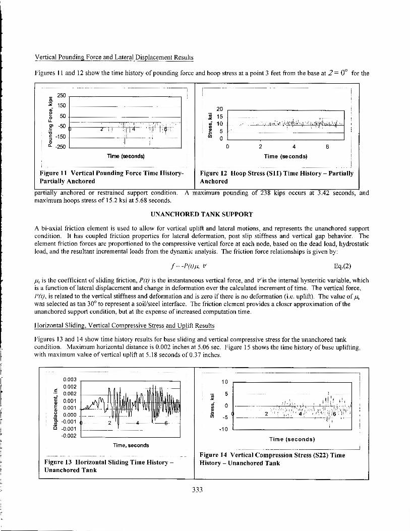
Vertical Pounding Force and Lateral Displacement Results
Figures 11 and 12 show the time history of pounding force and hoop stress at a point 3 feet from the base at 2 = 0° for the
partially anchored or restrained support condition. A maximum pounding of 238 kips occurs at 3.42 seconds, and maximum hoops stress of 15.2 ksi at 5.68 seconds.
UNANCHORED TANK SUPPORT
A bi-axial friction element is used to allow for vertical uplift and lateral motions, and represents the unanchored support condition. It has coupled friction properties for lateral deformation, post slip stiffness and vertical gap behavior. The element friction forces are proportioned to the compressive vertical force at each node, based on the dead load, hydrostatic load, and the resultant incremental loads from the dynamic analysis. The friction force relationships is given by:
f= -PNA Eq.(2)
p, is the coefficient of sliding friction, P(t) is the instantaneous vertical force, and Vis the internal hysteritic variable, which is a function of lateral displacement and change in deformation over the calculated increment of time. The vertical force, P(t), is related to the vertical stiffness and deformation and is zero if there is no deformation (i.e. uplift). The value of dus was selected as tan 30° to represent a soil/steel interface. The friction element provides a closer approximation of the unanchored support condition, but at the expense of increased computation time.
Horizontal Sliding, Vertical Compressive Stress and Uplift Results
Figures 13 and 14 show time history results for base sliding and vertical compressive stress for the unanchored tank condition. Maximum horizontal distance is 0.002 inches at 5.06 sec. Figure 15 shows the time history of base uplifting, with maximum value of vertical uplift at 5.18 seconds of 0.37 inches.
333
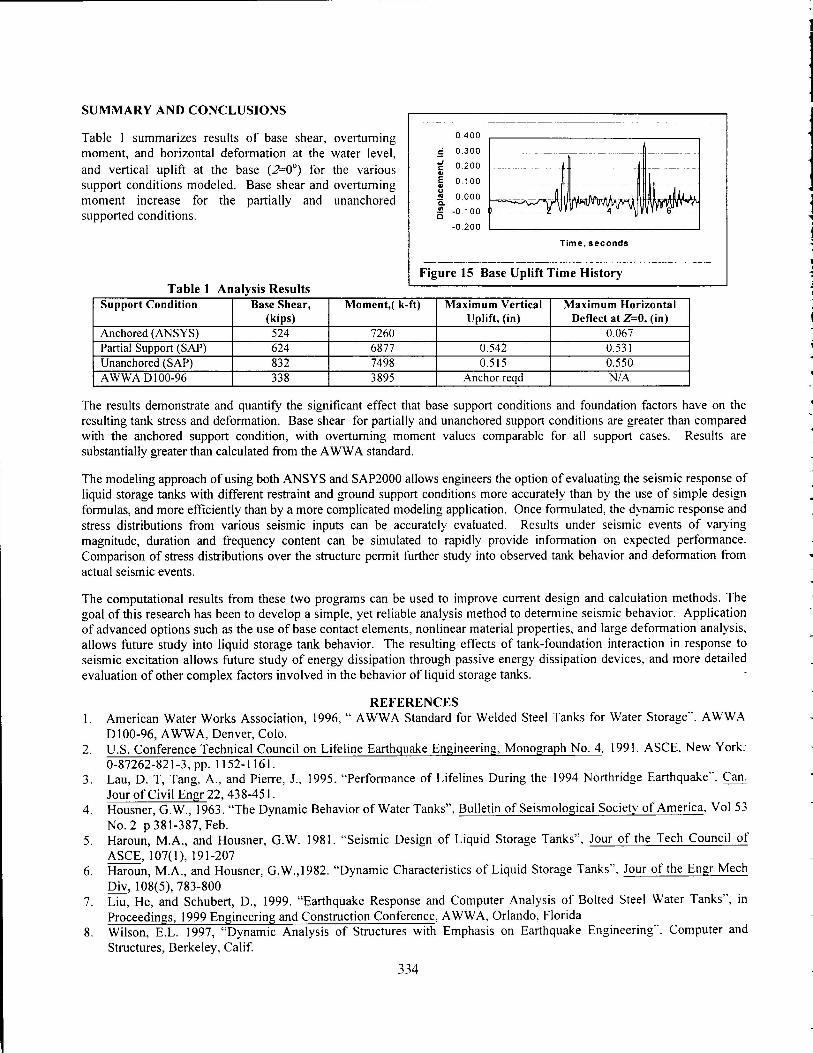
Time, seconds
Figure 15 Base Uplift Time History
Dis
pla
cem
en
t, in
.
0.400
0.300
0.200
0.100
0.000
-0.100
-0.200
SUMMARY AND CONCLUSIONS
Table 1 summarizes results of base shear, overturning moment, and horizontal deformation at the water level, and vertical uplift at the base (2=0°) for the various support conditions modeled. Base shear and overturning moment increase for the partially and unanchored supported conditions.
Table 1 Analysis Results Support Condition Base Shear,
(kips) Moment,( k-ft) Maximum Vertical
Uplift, (in) Maximum Horizontal
Deflect at Z=0, (in)
Anchored (ANSYS) 524 7260 0.067 Partial Support (SAP) 624 6877 0.542 0.531 Unanchored (SAP) 832 7498 0.515 0.550 AWWA D100-96 338 3895 Anchor reqd N/.A
The results demonstrate and quantify the significant effect that base support conditions and foundation factors have on the resulting tank stress and deformation. Base shear for partially and unanchored support conditions are greater than compared with the anchored support condition, with overturning moment values comparable for all support cases. Results are substantially greater than calculated from the AWWA standard.
The modeling approach of using both ANSYS and SAP2000 allows engineers the option of evaluating the seismic response of liquid storage tanks with different restraint and ground support conditions more accurately than by the use of simple design formulas, and more efficiently than by a more complicated modeling application. Once formulated, the dynamic response and stress distributions from various seismic inputs can be accurately evaluated. Results under seismic events of varying magnitude, duration and frequency content can be simulated to rapidly provide information on expected performance. Comparison of stress distributions over the structure permit further study into observed tank behavior and deformation from actual seismic events.
The computational results from these two programs can be used to improve current design and calculation methods. The goal of this research has been to develop a simple, yet reliable analysis method to determine seismic behavior. Application of advanced options such as the use of base contact elements, nonlinear material properties, and large deformation analysis, allows future study into liquid storage tank behavior. The resulting effects of tank-foundation interaction in response to seismic excitation allows future study of energy dissipation through passive energy dissipation devices, and more detailed evaluation of other complex factors involved in the behavior of liquid storage tanks.
REFERENCES 1. American Water Works Association, 1996, " AWWA Standard for Welded Steel Tanks for Water Storage". AWWA
D100-96, AWWA, Denver, Colo. 2. U.S. Conference Technical Council on Lifeline Earthquake Engineering, Monograph No. 4, 1991. ASCE, New York:
0-87262-821-3, pp. 1152-1161. 3. Lau, D. T, Tang, A., and Pierre, J., 1995. "Performance of Lifelines During the 1994 Northridge Earthquake-. Can.
Jour of Civil Engr 22, 438-451. 4. Housner, G.W., 1963. "The Dynamic Behavior of Water Tanks", Bulletin of Seismological Society of America, Vol 53
No. 2 p 381-387, Feb. 5. Haroun, M.A., and Housner, G.W. 1981. "Seismic Design of Liquid Storage Tanks", Jour of the Tech Council of
ASCE, 107(1), 191-207 6. Haroun, M.A., and Housner, G.W.,1982. "Dynamic Characteristics of Liquid Storage Tanks". Jour of the Engr Mech
Div, 108(5), 783-800 7. Liu, He, and Schubert, D., 1999. "Earthquake Response and Computer Analysis of Bolted Steel Water Tanks", in
Proceedings, 1999 Engineering and Construction Conference, AWWA, Orlando, Florida 8. Wilson, E.L. 1997, "Dynamic Analysis of Structures with Emphasis on Earthquake Engineering". Computer and
Structures, Berkeley, Calif.
334