Embed Size (px)
DESCRIPTION
segway project report
Citation preview

CHAPTER 1
INTRODUCTION TO SEGWAY VEHICLE
1.1. INTRODUCTION :
All vehicles that are in the market cause pollution and the fuel cost is also increasing day
by day. In order to compensate the fluctuating fuel cost and the pollution less good remedy is
needed i.e. our transporting system.
Due to ignition of the hydrocarbon fuels, in the vehicle, some time difficulties such as
wear and tear may be high and more attention is needed for proper maintenance. Our vehicle is
easy to handle and no fuel cost to the other existing vehicles.
Since the last two decades the judiciary and policy makers all over the world are deeply
concerned about the urgent need for protection of the environment, ecology and humanity at
large, there has been a steep rise in the accumulation of green house gases particularly CO₂,
which effect global changes in weather. Motor vehicle contribute about 14% of CO₂ from all
sources besides, pollution due to both petrol and diesel engine driven vehicles caused by the
emission of CO, no unburnt hydrocarbons, particulate and oxides of tetra ethyl, Lead are injury
to health and environment.
Regulations on exhaust emission from vehicle engines have been made progressively more and
more stipend towards the year 2000 and beyond, Vehicle manufactures have been hence obliged
to meet these standards by designing cleaner and fuel efficiently engines and through provision
for treatment of exhaust gases to satisfy the specified limits. So to satisfy and overcome these
two problems namely
Pollution and
Efficiency
1

Hence a need for a change in the existing alternative system which can produce higher
efficiency at minimum cost was though about an attempt has been made to design and fabricate
such an alternative system.
So this project “SEGWAY VEHICLE” is very much useful, since it is provided with
good quality of power sources and simple operating mechanism. Hence “EACH AND EVERY
DROP OF FUEL SAVES OUR ECONOMY AND MEET THE NEEDS” is the saturation point
that is to be attained as soon as possible.
In order to achieve this saturation point we have to save and seek for some other source
of power. This power, the alternate power must be much more convenient in availability and
usage.
The next important reason for the search of effective, unadulterated power are to save the
surrounding environments including men, machine and material of both the existing and the next
forth generation from pollution, the cause for many harmful happenings and to reach the
saturation point.
The most talented power against the natural resource is supposed to be the electric and
energies that best suit the automobiles. The unadulterated zero emission electrical and power, is
the only easily attainable alternate source.
Hence we decided to incorporate the power in the field of automobile, the concept of
many Multi National Companies (MNC) and to get relieved from the incorrigible air pollution.
1.2. History of Segway Vehicle :
The Segway was known by the names Ginger and IT before it was unveiled. Ginger came
out of the first product that used Kamen's balancing technology, the iBOT wheelchair.
During development at the University of Plymouth, in conjunction with BAE
Systems and Sumitomo Precision Products, the iBot was nicknamed Fred
2

Upstairs (after Fred Astaire) because it can climb stairs: hence the name Ginger, after
Astaire's regular film partner, Ginger Rogers, for a successor product.
The invention, development, and financing of the Segway was the subject of a narrative
nonfiction book, Code Name Ginger (in paperback as Reinventing the Wheel), by
journalist Steve Kemper. The leak of information from that book led to speculation about
the "IT" device prior to release. The speculation created an unexpected advance buzz
about the product that was, at times, hyperbolic. Steve Jobs was quoted as saying that it
was "as big a deal as the PC",[1] though later sources quoted him as saying when first
introduced to the product that its design "sucked".[2] John Doerr speculated that it would
be more important than the Internet.[1]Articles were written in major publications
speculating on it being a Stirling engine.[3] South Park devoted an episode to making fun
of the hype before the product was released.
The product was unveiled 3 December 2001, in Bryant Park, the privately managed
public park located in the New York City boroughof Manhattan, on the ABC
News morning program Good Morning America.
1.3 Basic Working Principle of Segway Vehicle :
When Dean Kamen unveiled the Segway Vehicle on ABC's Good Morning America, he
described the machine as "the world's first human transporter." When you look at the
machine in motion, you get an idea of what he's talking about. Unlike a car, the Segway
only has two wheels-it looks something like an ordinary hand truck-yet it manages to stay
upright by itself.To move forward,right and left on the Segway, the segway is To move
forward and turn left or right, simply by using switches this switches connected by
control pannel. it is the key to its operation. This vehicle is moved by electrical power.
this power stored in lead acid battries.
3

CHAPTER 2
COMPONENTS OF SEGWAY VEHICLE
SEGWAY VEHICLE COMPONENTS:
SEGWAY VEHICLE Components are mainly classified into two Components they are
given below.
1. Mechanical Components
2. Electrical Components
2.1 MECHANICAL COMPONENTS:
The main mechanical components of SEGWAY VEHICLE are as follows
Body And Frame
Wheels And Tires
Bearings
2.1.1BODY:
The term is usually reserved for bodies built on a separate frame, rather than being of unitary
or monocoque construction. With reference to motor vehicles, auto body is the standard term in
North American English.
2.1.1 FRAME:
A frame is the main structure of the motor vehicle. All other components fasten to it; term for
this design is body-on-frame construction. In which it gives strength to the body of vehicle.
FUNCTIONS:
4
The main functions of a frame in motor vehicle are
1. To support the vehicle’s components and body
2. To deal with static and dynamic loads, without undue deflection or distortion.
These include:
Weight of the body, passenger, and cargo loads.
Vertical and torsion twisting transmitted by going over uneven surfaces.
Torque from the motors.
Sudden impacts from collisions.
DESIGN FEATURES:
While appearing at first glance as a simple hunk of metal, frame encounter great amounts
of stress and are built accordingly. The first issue addressed is beam height and tapper of body.
The body and frame is made of mild steel sheet and hallow square bars with a thickness
of 2mm each.
Fig.2.1 Mild Steel Square Hallow Bar
5
Fig.2.2 Mild Steel Sheet
Fig.2.3 Vehicle body
Fig.2.4 Frame of
Vehicle
2.1.2 WHEEL AND TIRES:
6

Wheels:
Coming to wheels we use two types of wheels to SEGWAY VEHICLE. They are as
follows
To the front of the vehicle we use two electric bike wheels.
To the rear of the vehicle we use single small turning wheel.
Tires:
To the front of the vehicle we use two NYLON bike tires.
To the rear of the vehicle we use single FIBRE turning wheel.
Fig.2.5 Nylon Tired Wheel
7

Fig.2.6 Fiber Turning Wheel
2.1.3 Bearings:
A ball bearing is a type of rolling-element bearing that uses balls to maintain the
separation between the bearing races.
The purpose of a ball bearing is to reduce rotational friction and support radial and
axial loads. It achieves this by using at least two races to contain the balls and transmit the loads
through the balls. In most applications, one race is stationary and the other is attached to the
rotating assembly (e.g., a hub or shaft). As one of the bearing races rotates it causes the balls to
rotate as well. Because the balls are rolling they have a much lower coefficient of friction than if
two flat surfaces were sliding against each other.
Fig.2.7 Inner and Outer Races of Ball Bearing
8

Ball bearings tend to have lower load capacity for their size than other kinds of rolling-
element bearings due to the smaller contact area between the balls and races. However, they can
tolerate some misalignment of the inner and outer races.
Fig.2.8 Ball Bearing
2.2 ELECTRICAL COMPONENTS:
The Electrical components of SEGWAY VEHICLE are as follows
Batteries
Motors
Micro controller
2.2.1 BATTERIES:
INTRODUCTION:
In isolated systems away from the grid, batteries are used for storage of excess energy
converted into electrical energy. The only exceptions are isolated sunshine load such as
irrigation pumps or drinking water supplies for storage. In fact for small units with output less
than one kilowatt. Batteries seem to be the only technically and economically available storage
means. Since both the photo-voltaic system and batteries are high in capital costs. It is
9

necessary that the overall system be optimized with respect to available energy and local demand
pattern. To be economically attractive the storage of electricity requires a battery with a
particular combination of properties:
(1) Low cost
(2) Long life
(3) High reliability
(4) High overall efficiency
(5) Low discharge
(6) Minimum maintenance
(A) Ampere hour efficiency
(B) Watt hour efficiency
We use lead acid battery for storing the electrical energy from the battery for lighting the
street and so about the lead acid cells are explained below.
LEAD-ACID WET CELL:
Where high values of load current are necessary, the lead-acid cell is the type most
commonly used. The electrolyte is a dilute solution of sulfuric acid (H₂SO₄). In the application
of battery power to start the engine in an auto mobile, for example, the load current to the starter
motor is typically 200 to 400A. One cell has a nominal output of 2.1V, but lead-acid cells are
often used in a series combination of three for a 6-V battery and six for a 12-V battery.
The lead acid cell type is a secondary cell or storage cell, which can be recharged. The
charge and discharge cycle can be repeated many times to restore the output voltage, as long as
the cell is in good physical condition. However, heat with excessive charge and discharge
currents shortends the useful life to about 3 to 5 years for an automobile battery. Of the different
types of secondary cells, the lead-acid type has the highest output voltage, which allows fewer
cells for a specified battery voltage.
10

Fig.2.9 2 x 12Volts Lead Acid Batteries
Fig.2.10. Lead Acid Battery
11

CONSTRUCTION:
Inside a lead-acid battery, the positive and negative electrodes consist of a group of plates
welded to a connecting strap. The plates are immersed in the electrolyte, consisting of 8 parts of
water to 3 parts of concentrated sulfuric acid. Each plate is a grid or framework, made of a lead-
antimony alloy. This construction enables the active material, which is lead oxide, to be pasted
into the grid. In manufacture of the cell, a forming charge produces the positive and negative
electrodes. In the forming process, the active material in the positive plate is changed to lead
peroxide (pbo₂). The negative electrode is spongy lead (pb).
Automobile batteries are usually shipped dry from the manufacturer. The electrolyte is
put in at the time of installation, and then the battery is charged to from the plates. With
maintenance-free batteries, little or no water need be added in normal service. Some types are
sealed, except for a pressure vent, without provision for adding water.
CHEMICAL ACTION:
Sulfuric acid is a combination of hydrogen and sulfate ions. When the cell discharges,
lead peroxide from the positive electrode combines with hydrogen ions to form water and with
sulfate ions to form lead sulfate. Combining lead on the negative plate with sulfate ions also
produces he sulfate. There fore, the net result of discharge is to produce more water, which
dilutes the electrolyte, and to form lead sulfate on the plates.
As the discharge continues, the sulfate fills the pores of the grids, retarding circulation of
acid in the active material. Lead sulfate is the powder often seen on the outside terminals of old
batteries. When the combination of weak electrolyte and sulfating on the plate lowers the output
of the battery, charging is necessary.
12

On charge, the external D.C. source reverses the current in the battery. The reversed
direction of ions flows in the electrolyte result in a reversal of the chemical reactions. Now the
lead sulfates on the positive plate reactive with the water and sulfate ions to produce lead
peroxide and sulfuric acid. This action re-forms the positive plates and makes the electrolyte
stronger by adding sulfuric acid.
Fig.2.11 Chemical Reaction In Lead Acid Battery
13

At the same time, charging enables the lead sulfate on the negative plate to react with
hydrogen ions; this also forms sulfuric acid while reforming lead on the negative plate to react
with hydrogen ions; this also forms currents can restore the cell to full output, with lead peroxide
on the positive plates, spongy lead on the negative plate, and the required concentration of
sulfuric acid in the electrolyte.
The chemical equation for the lead-acid cell is
Charge
Pb + pbO₂ + 2H₂SO₄ 2pbSO₄ + 2H₂O
Discharge
On discharge, the pb and pbo₂ combine with the SO₄ ions at the left side of the equation
to form lead sulfate (pbSO₄) and water (H₂O) at the right side of the equation.
One battery consists of 6 cell, each have an output voltage of 2.1V, which are connected
in series to get an voltage of 12V and the same 12V battery is connected in series, to get an 24 V
battery. They are placed in the water proof iron casing box.
CARING FOR LEAD-ACID BATTERIES:
Always use extreme caution when handling batteries and electrolyte. Wear gloves,
goggles and old clothes. “Battery acid” will burn skin and eyes and destroy cotton and wool
clothing.
The quickest way of ruin lead-acid batteries is to discharge them deeply and leave them
stand “dead” for an extended period of time. When they discharge, there is a chemical change in
the positive plates of the battery. They change from lead oxide when charge out lead sulfate
14

when discharged. If they remain in the lead Sulfate State for a few days, some part of the plate
dose not returns to lead oxide when the battery is recharged. If the battery remains discharge
longer, a greater amount of the positive plate will remain lead sulfate. The parts of the plates that
become “sulfate” no longer store energy. Batteries that are deeply discharged, and then charged
partially on a regular basis can fail in less then one year.
Check your batteries on a regular basis to be sure they are getting charged. Use a
hydrometer to check the specific gravity of your lead acid batteries. If batteries are cycled very
deeply and then recharged quickly, the specific gravity reading will be lower than it should
because the electrolyte at the top of the battery may not have mixed with the “charged”
electrolyte.
Check the electrolyte level in the wet-cell batteries at the least four times a year and top
each cell of with distilled water. Do not add water to discharged batteries. Electrolyte is
absorbed when batteries are very discharged. If you add water at this time, and then recharge the
battery, electrolyte will overflow and make a mess.
Keep the top of your batteries clean and check that cables are tight. Do not tighten or
remove cables while charging or discharging. Any spark around batteries can cause a hydrogen
explosion inside, and ruin one of the cells, and you.
On charge, with reverse current through the electrolyte, the chemical action is reversed.
Then the pb ions from the lead sulfate on the right side of the equation re-form the lead and lead
peroxide electrodes. Also the SO₄ ions combine with H₂ ions from the water to produce more
sulfuric acid at the left side of the equation.
CURRENT RATINGS:
Lead-acid batteries are generally rated in terms of how much discharge currents they can
supply for a specified period of time; the output voltage must be maintained above a minimum
level, which is 1.5 to 1.8V per cell. A common rating is ampere-hours (A.h.) based on a specific
discharge time, which is often 8h. Typical values for automobile batteries are 100 to 300 A.h.
15

As an example, a 200 A.h battery can supply a load current of 200/8 or 25A, used on 8h
discharge. The battery can supply less current for a longer time or more current for a shorter
time. Automobile batteries may be rated for “cold cranking power”, which is related to the job
of starting the engine. A typical rating is 450A for 30s at a temperature of 0 degree F.
Note that the ampere-hour unit specifies coulombs of charge. For instance, 200 A.h.
corresponds to 200A*3600s (1h=3600s). the equals 720,000 A.S, or coulombs. One ampere-
second is equal to one coulomb. Then the charge equals 720,000 or 7.2*10^5ºC. To put this
much charge back into the battery would require 20 hours with a charging current of 10A.
The ratings for lead-acid batteries are given for a temperature range of 77 to 80ºF.
Higher temperature increase the chemical reaction, but operation above 110ºF shortens the
battery life.
Low temperatures reduce the current capacity and voltage output. The ampere-hour
capacity is reduced approximately 0.75% for each decreases of 1º F below normal temperature
rating. At 0ºF the available output is only 60 % of the ampere-hour battery rating.
In cold weather, therefore, it is very important to have an automobile battery unto full
charge. In addition, the electrolyte freezes more easily when diluted by water in the discharged
condition.
SPECIFIC GRAVITY:
Measuring the specific gravity of the electrolyte generally checks the state of discharge
for a lead-acid cell. Specific gravity is a ratio comparing the weight of a substance with the
weight of a substance with the weight of water. For instance, concentrated sulfuric acid is 1.835
times as heavy as water for the same volume. Therefore, its specific gravity equals 1.835. The
specific gravity of water is 1, since it is the reference.
16

In a fully charged automotive cell, mixture of sulfuric acid and water results in a specific
gravity of 1.280 at room temperatures of 70 to 80ºF. as the cell discharges, more water is
formed, lowering the specific gravity. When it is down to about 1.150, the cell is completely
discharged.
Specific-gravity readings are taken with a battery hydrometer, such as one in figure (7).
Note that the calibrated float with the specific gravity marks will rest higher in an electrolyte of
higher specific gravity.
The decimal point is often omitted for convenience. For example, the value of 1.220 in
figure (7) is simply read “twelve twenty”. A hydrometer reading of 1260 to 1280 indicates full
charge, approximately 12.50 are half charge, and 1150 to 1200 indicates complete discharge.
The importance of the specific gravity can be seen from the fact that the open-circuit
voltage of the lead-acid cell is approximately equal to
V = Specific gravity + 0.84
For the specific gravity of 1.280, the voltage is 1.280 = 0.84 = 2.12V, as an example.
These values are for a fully charged battery.
CHARGING THE LEAD-ACID BATTERY:
The requirements are illustrated in figure. An external D.C. voltage source is necessary
to produce current in one direction. Also, the charging voltage must be more than the battery
e.m.f. Approximately 2.5 per cell are enough to over the cell e.m.f. so that the charging voltage
can produce current opposite to the direction of discharge current.
17

Note that the reversal of current is obtained just by connecting the battery VB and
charging source VG with + to + and –to-, as shown in figure. The charging current is reversed
because the battery effectively becomes a load resistance for VG when it higher than VB. In this
example, the net voltage available to produce charging currents is 15-12=3V.
A commercial charger for automobile batteries is essentially a D.C. power supply,
rectifying input from the AC power line to provide D.C. output for charging batteries.
Float charging refers to a method in which the charger and the battery are always
connected to each other for supplying current to the load. In figure the charger provides current
for the load and the current necessary to keep the battery fully charged. The battery here is an
auxiliary source for D.C. power.
It may be of interest to note that an automobile battery is in a floating-charge circuit. The
battery charger is an AC generator or alternator with rectifier diodes, driver by a belt from the
engine. When you start the car, the battery supplies the cranking power. Once the engine is
running, the alternator charges he battery. It is not necessary for the car to be moving. A voltage
regulator is used in this system to maintain the output at approximately 13 to 15 V.
The constant voltage of 24V comes from the battery controlled by the charge controller
so for storing this energy we need a 24V battery so two 12V battery are connected in series.
It is a good idea to do an equalizing charge when some cells show a variation of 0.05
specific gravity from each other. This is a long steady overcharge, bringing the battery to a
gassing or bubbling state. Do not equalize sealed or gel type batteries.
With proper care, lead-acid batteries will have a long service life and work very well in
almost any power system. Unfortunately, with poor treatment lead-acid battery life will be very
short.
18

2.2.2 MOTOR:
D.C. MOTOR (PERMANENT MAGNET):
DESCRIPTION OF DC MOTOR
An electric motor is a machine which converts electrical energy to mechanical energy.
Its action is based on the principle that when a current-carrying conductor is placed in a magnetic
field, it experiences a magnetic force whose direction is given by Fleming’s left hand rule.
When a motor is in operation, it develops torque. This torque can produce mechanical
rotation. DC motors are also like generators classified into shunt wound or series wound or
compound wound motors.
FLEMING’S LEFT HAND RULE:
Keep the force finger, middle finger and thumb of the left hand mutually perpendicular to
one another. If the fore finger indicates the direction of magnetic field and middle finger
indicates direction of current in the conductor, then the thumb indicates the direction of the
motion of conductor.
PRINCIPLE OF OPERATION OF DC MOTOR:
Figure I show a uniform magnetic field in which a straight conductor carrying no current
is placed. The conductor is perpendicular to the direction of the magnetic field.
In figure II the conductor is shown as carrying a current away from the viewer, but the
field due to the N and S poles has been removed. There is no movement of the conductor during
the above two conditions. In figure III the current carrying conductor is placed in the magnetic
19

field. The field due to the current in the conductor supports the main field above the conductor,
but opposes the main field below the conductor.
Movement of
Conductor
Magnetic flux current carrying
Conductor
Fig.2.12 Operation of DC Motor
The result is to increase the flux density in to the region directly above the conductor and
to reduce the flux density in the region directly below the conductor. It is found that a force acts
on the conductor, trying to push the conductor downwards as shown by the arrow. If the current
in the conductor is reversed, the strengthening of flux lines occurs below the conductor, and the
conductor will be pushed upwards (figure-IV).
Now consider a single turn coil carrying a current as shown in the above figure. in view
of the reasons given above, the coil side A will be forced to move downwards, whereas the coil
side B will be forced to move upwards. The forces acting on the coil sides A and B will be of
same magnitude. But their direction is opposite to one another. As the coil is wound on the
armature core which is supported by the bearings, the armature will now rotate. The commutator
20
N S

periodically reverses the direction of current flow through the armature. Therefore the armature
will have a continuous rotation.
A simplified model of such a motor is shown in figure VI. The conductors are wound
over a soft iron core. DC supply is given to the field poles for producing flux. The conductors
are connected to the DC supply through brushes
Let's start by looking at the overall plan of a simple 2-pole DC electric motor. A simple
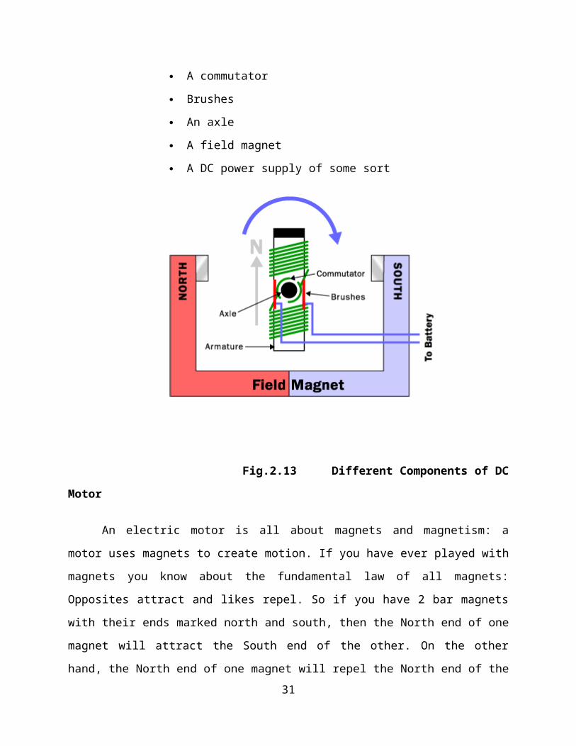
motor has 6 parts, as shown in the diagram below.
An armature or rotor
A commutator
Brushes
An axle
A field magnet
A DC power supply of some sort
Fig.2.13 Different Components of DC Motor
21

An electric motor is all about magnets and magnetism: a motor uses magnets to create
motion. If you have ever played with magnets you know about the fundamental law of all
magnets: Opposites attract and likes repel. So if you have 2 bar magnets with their ends marked
north and south, then the North end of one magnet will attract the South end of the other. On the
other hand, the North end of one magnet will repel the North end of the other (and similarly
south will repel south). Inside an electric motor these attracting and repelling forces create
rotational motion.
In the diagram above and below you can see two magnets in the motor, the armature (or
rotor) is an electromagnet, while the field magnet is a permanent magnet (the field magnet could
be an electromagnet as well, but in most small motors it is not to save power).
Electromagnets and Motors:
To understand how an electric motor works, the key is to understand how the
electromagnet works. An electromagnet is the basis of an electric motor. You can understand
how things work in the motor by imagining the following scenario. Say that you created a simple
electromagnet by wrapping 100 loops of wire around a nail and connecting it to a battery. The
nail would become a magnet and have a North and South pole while the battery is connected.
Now say that you take your nail electromagnet, run an axle through the middle of it, and
you suspended it in the middle of a horseshoe magnet as shown in the figure below. If you were
to attach a battery to the electromagnet so that the North end of the nail appeared as shown, the
basic law of magnetism tells you what would happen: The North end of the electromagnet would
be repelled from the north end of the horseshoe magnet and attracted to the south end of the
horseshoe magnet.
The South end of the electromagnet would be repelled in a similar way. The nail would
move about half a turn and then stop in the position shown.
22

You can see that this half-turn of motion is simple and obvious because of the way
magnets naturally attract and repel one another. The key to an electric motor is to then go one
step further so that, at the moment that this half-turn of motion completes, the field of the
electromagnet flips. The flip causes the electromagnet to complete another half- turn of
motion.
You flip the magnetic field simply by changing the direction of the electrons flowing in
the wire (you do that by flipping the battery over). If the field of the electromagnet flipped at just
the right moment at the end of each half-turn of motion, the electric motor would spin freely.
Fig.2.14 Horseshoe Magnetic Motor
23

The Armature:
The armature takes the place of the nail in an electric motor. The armature is an
electromagnet made by coiling thin wire around two or more poles of a metal core. The armature
has an axle, and the commutator is attached to the axle. In the diagram above you can see three
different views of the same armature: front, side and end-on. In the end-on view the winding is
eliminated to make the commutator more obvious. You can see that the commutator is simply a
pair of plates attached to the axle. These plates provide the two connections for the coil of the
electromagnet.
Fig.2.15 Armature
The Commutator and brushes:
The "flipping the electric field" part of an electric motor is accomplished by two parts:
the commutator and the brushes. The diagram at the right shows how the commutator and
brushes work together to let current flow to the electromagnet, and also to flip the direction that
the electrons are flowing at just the right moment. The contacts of the commutator are attached
to the axle of the electromagnet, so they spin with the magnet. The brushes are just two pieces of
springy metal or carbon that make contact with the contacts of the commutator.
24

Fig.2.16 The Combination of All Parts of Motor
Fig.2. Commutator and
Brushes
25

Putting It All Together:
When you put all of these parts together, what you have is a complete electric motor:
In this figure, the armature winding has been left out so that it is easier to see the
commutator in action. The key thing to notice is that as the armature passes through the
horizontal position, the poles of the electromagnet flip. Because of the flip, the North pole of the
electromagnet is always above the axle so it can repel the field magnet's North pole and attract
the field magnet's South pole.
If you ever take apart an electric motor you will find that it contains the same pieces
described above: two small permanent magnets, a commutator, two brushes and an
electromagnet made by winding wire around a piece of metal. Almost always, however,
the rotor will have three poles rather than the two poles as shown in this article. There are
two good reasons for a motor to have three poles:
It causes the motor to have better dynamics. In a two-pole motor, if the electromagnet is
at the balance point, perfectly horizontal between the two poles of the field magnet when
the motor starts; you can imagine the armature getting "stuck" there. That never happens
in a three-pole motor.
Each time the commutator hits the point where it flips the field in a two-pole motor, the
commutator shorts out the battery (directly connects the positive and negative terminals)
for a moment. This shorting wastes energy and drains the battery needlessly. A three-pole
motor solves this problem as well.
26

It is possible to have any number of poles, depending on the size of the motor and the
specific application it is being used in.
Fig.2.18 12 Volts Right angled D.C Motor
2.2.3 MICRO CONTROLLER:
The micro controller takes the energy from the batteries to operate the motors with the help
of switch board.
The MICRO CONTROLLER is connected with following components
Batteries
Motors
Switch board
27

Fig.2.19 Micro Controller
28

2.3 ELECTRICAL CIRCUIT DESIGN:
The below figure shows the electrical circuit design used for SEGWAY VEHICLE
Fig.2.20 Micro Controller Circuit Design
29

2.4 SPECIFICATIONS:
Motor Specification
Model Rated
Volt.
No Load At Max Efficiency
Speed Current Speed Current Torque Power
rpm mA rpm mA Kgf.cm W
12 Volts Right Angled Geared DC Motor 12V 184 420 160 2160 3.5 5.75
Battery Specification
Type Voltage regulation Max .initial current
Standby use 13.6v – 13.8v 2.16 amps
Cycle use 14.4v – 14.8v 2.16 amps
30
CHAPTER 3
NEED FOR NON-CONVENTIONAL ENERGY
SOURCES
NEED FOR NON-CONVENTIONAL ENERGY SOURCES
Energy is the primary and most universal measure of all kinds of work by human beings
and nature. Every thing what happens in the world is the expression of flow of energy for input
to their bodies or to the machines and thinks about crude and electric power. The energy sources
available can be divided into 3 types:
1. PRIMARY ENERGY SOURCES
2. SECONDARY FUELS
3. WORLD ENERGY FUTURE
3.1 PRIMARY ENERGY SOURCES:
Primary energy sources can be defined as sources, which provide a net energy.
Coal, Oil, uranium etc, are examples of this type. The energy required to obtain these fuels is
much less than what they can produces by combustion or nuclear reaction. Their energy yield
ratio is defined as the energy feedback by the material to energy received from the environment
becomes very essential to use these fuels sparingly. Primary fuels contribute concededly to the
energy supply.
3.2 SECONDARY FUELS:
It produces no net energy though it may net energy yield ratio and those highest
investments in terms of energy. Insulation is an example for this source.
31

Coal, Natural gas, Oil and Nuclear energy using Breeder reactor are net energy yielder
and are primary sources of energy. Secondary sources like energy, Wind energy, Water energy
etc. energy can be used through plants, cells and heaters. tower is another emerging
technology. drying and heating are economical applications when passive methods are used.
Because of dilute nature of energy it is difficult to classify the sources as primary one. Better
sources are wind.
Tidal, wave and hydroelectric application, Geo thermal and ocean thermal are other sources,
which may well prove worthwhile. It may be necessary in future to develop the secondary
sources like, wind etc.
Energy is an important input in all sectors of any country economy. The standard of a
given country can be directly related to per capital energy consumption. Energy crisis is due to
two reasons first the increase of population and the second is the standard of living of human
being has increased.
The supply of oil will fail to meet the increasing demand before the year 2020 even if
energy crisis rise 50% above current levels in real terms. Additional constraints on oil
production will hasten this shortage, there by reducing the time available for action on
alternatives.
Electricity from nuclear power is capable of making an important contribution to the global
energy supply although worldwide acceptance of it, on a sufficiently large scales yet to be
established. Fusion power will not be sufficient before the end of 2020.
3.3 WORLD ENERGY FUTURE:
If present trend continues, the world in the year 2020 A.D. will be more crowded than that of
today. The world population may reach 10 billion by 2020 A.D. the conventional energy sources
are depleting and may be exhausted by the beginning of next century. Nuclear energy requires
skilled technician and poses the safety as regards to radioactive waste disposal. energy and
other non-conventional energy sources are to be utilized in future. Coal has the potential to
contribute substantially to the future energy supplies. Coal reserves are abundant but taking
32

advantages of them requires an active program of development by both producers and
consumers.
Natural gas reserves are large enough to meet projected demand provided the incentives are
sufficient to encourage development of extensive and costly inter continental gas transportation
system.
Other than hydro electric power, renewable resources of energy example , wind, wave are
unlikely to contribute significant quantities of additional energy during the century at global
level although they could be of importance in particular areas they are likely to become
increasingly important in the mid of 21st century.
3.4 NEED FOR NON-CONVENTIONAL ENERGY:
Fuel deposit in the world will soon deplete by the end of 2020 Fuel security will be
maximum. Country using petroleum will not have the chance to use petroleum products.
Keeping this dangerous situation in mind, we tried to make use of non-pollutant natural resource
of energy.
The creation of new source of perennial is environmental acceptable. Low cost electrical
energy as replacement for energy from rapidly depleting resources of fossil fuels is the
fundamental need for the survival of mankind.
We have oil resources for about 25 Yr. And coal reserves for about 75-100 Yr. Resort to
measure the beginning of coal in thermal electric. Power station to service the population would
result in global elementary change in leading to world wide draught and desertification. The
hazards of nuclear electric power station are more & huge.
Now electric power beamed directly by microwave for orbiting statuette. power stations
(s.p.s) provide a cost effective solution every through many certain have extensively proceed
work on photo voltaic and thermal electric energy resources.
33

Earth based power station suffer certain basic limitation. It is not possible to consider
such system and meeting continuous uninterrupted concentrated base load electric power
requirement.
3.5 UTILISATION OF ENERGY
3.5.1 CONCEPT:
In 1968 Dr. Peter Glaser in the U.S. published an idea centered on the fat that in orbit close
to earth, 1.35 KW of energy illuminates one square meter which is considerably greater and one
more continuous than anyone square meter on the earth which, even when perpendicular to the
sun can receive only a maximum of 1 KW.
His idea was converting sunlight to electricity to convert in to frequency signal and beam
down to the earth caring significant levels of energy. This electricity is by establishing a very
large array of cell in geo stationary orbit. A receiving antenna station on the earth would convert
this radio frequency back into an alternate current which would a fed in to a local grit.
3.5.2 ENERGY:
Energy has the greatest potential of the sources of renewable energy and if only a small
amount of this form of energy could be used.
radiation is the diffusion radiation. The power where sun hits atmosphere is 10¹⁷ watts.
Where as the power on earth’s surface is 10¹⁶ watts. The total worldwide power demand of all
needs of civilization is 10¹³ watts. Therefore the sun gives as 1000 times more power than we
need.
The sun radiates energy as electromagnetic waves of which 99 percent have wavelengths
in the range of 0.2 to 4.0 meters. energy reaching the top of the earth’s atmosphere consists of
about 8 percent ultraviolet radiation, 46 percent visible lights, and 46 % infrared Radiation.
If we use only 5% of energy it will be 50 times what the world will require. The energy
radiated by the sun on a bright sunny day is approximately 1 km/m².
34

Now days the drawbacks as pointed out that energy cannot be stored and it is a dilute
form of energy, are not dated arguments. Utilization of energy is of great importance to India,
since of lies in a temperature climate of the region of the world where sunlight is abundant for a
major part of year. energy is a time dependent and intermitted energy Resource.
In general energy needs or demands for a very wide variety of applications are also time
dependent, but in an entirely different manner from the energy supply. Here is thus a marked
need for the storage of energy or another product of the process, is the energy is to meet the
energy needs.
This problem is especially severe for energy when it is used for beating in winter,
because of its low availability during this period. So, we need optimally designed electric
system will collect and convert the energy into electrical energy when the isolation is available
during the day period and also optimally designed energy storage systems are needed for storing
the converted electrical energy.
3.6 METHODS OF UTILISATION OF ENERGY
1. DIRECT METHOD
a. Photo Voltaic Method
b. Thermal Method
2. INDIRECT METHOD
a. Water Power Method
b. Wind Power Method
c. Bio Mass Method
d. Wave Energy Method
35

e. Ocean Power Method
3.6. DIRECT METHOD OF UTILIZATION OF ENERGY:
The most useful way of harnessing energy is by directly converting it into electricity by
means of photo-voltaic cells. Sunshine is incident on cells, in this system of energy Conversion
that is direct conversion of radiation into electricity.
In the stage of conversion into thermodynamic from is absent. The photo-voltaic effect
is defined as the generation of an electromotive force as a result of the absorption of ionizing
radiation. Energy conversion devices, which are used to convert sunlight to electricity by use of
the photo-voltaic effect, are called cells.
In recent years photo-voltaic power generation has been receiving considerable attention
as one of the more promising energy alternatives. The reason for this rising interest lie in PV’s
direct conversion of sunlight to electricity, the non polluting nature of the PV widespread are of
PV generation has been hampered by economic factors. Here to force, the low cost of
conventional energy sunlight has obviated the development of a broad-based PV technology.
At the present time, PV generation can be justified only for special situations mostly for
remote sites where utility lines on other conventional means of furnishing energy may be
prohibitively expensive and is one of the most attractive non-conventional energy sources of
proven reliability from the micro to the Mega-watt level.
Like other energy system this system also has some disadvantages
(1) Distributed nature of energy,
(2) Absence of energy storage,
(3) Relatively high capital cost.
36

3.6.1 PHOTO VOLTAIC METHOD:
PHOTOVOLTAIC PRINCIPLES:
The photo-voltaic effect can be observed in nature in a variety of materials that have
shown that the best performance in sunlight is the semiconductors as stated above.
Fig.3.1 Photo Voltaic Effect
When photons from the sun are absorbed in a semiconductor, that create free electrons
with higher energies than the created there must be an electric field to induce these higher energy
electrons to flow out of the semi-conductor to do useful work. A junction of materials, which
have different electrical properties, provides the electric field in most cells.
37

Fig.3.2 Light to Electricity Convers
To obtain a useful power output from photon interaction in a semiconductor, three
processes are required.
1) The photon has to be absorbed in the active part of the material and result in
electrons being excited to a higher energy potential.
2) The electron hole charge carriers created by the absorption must be physically
separated and moved to the edge of the cell.
3) The charge carriers must be removed from the cell and delivered to useful load
before they loose extra potential.
38

For completing the above processes a cell consists of:-
(a) Semi-conductor in which electron hole pairs are created by absorption of
incident radiation.
(b) Region containing a drift field for charge separation
(c) Charge collecting fronts and back electrodes.
The photo-voltaic effect can be described easily for p-n junction in a semi-conductor. In
an intrinsic semi-conductor such as silicon, each one of the four valence electrons of the material
atom is tied in a chemical bond, and there are no free electrons at absolute zero. If a piece of
such a material is doped on one side by a five valance electron material, such as arsenic or
phosphorus, there will be an excess of electrons in that side, becoming an n-type semi-conductor.
The excess electrons will be practically free to move in the semi-conductor lattice. When
a three valence electron material, such as boron dopes the other side of the same piece, there will
be deficiency of electrons leading to a p-type semi-conductor. This deficiency is expressed in
terms of excess of holes free to move in the lattice. Such a piece of semi-conductor with one
side of the p-type and the other, of the n-type is called p-n junction. In this junction after the
protons are absorbed, the free electrons of the n-side will tends to flow to the p-side, and the
holes of the p-side will tend to flow to the n-region to compensate for their respective
deficiencies. This diffusion will create an electric field from the n-region to the p-region. This
field will increase until it reaches equilibrium for V, the sum of the diffusion potentials for holes
and electrons.
COMMISSIONING:
During the day time the battery gets charged and when the intensity of light decreases,
the LDR makes the light to gets ON and the light glows by using the stored charge in the battery.
Thus the given project is completed and commissioned.
39
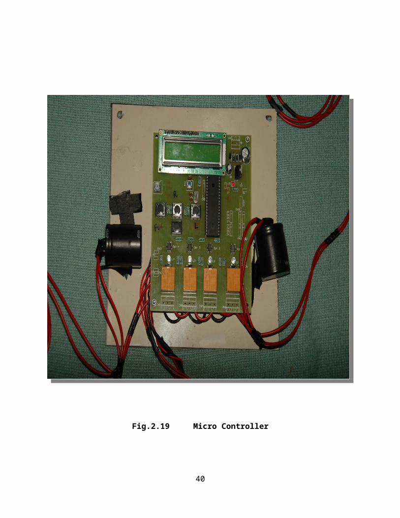
Fig.3.3 P-N Junction Bias
If electrical contacts are made with the two semiconductor materials and the contacts the
connected through an external electrical conductor, the free electrons will flow from the n-type
material through the conductor to the p-type material (figure). Here the free electrons will enter
the holes and holes and become bound electrons thus both free electrons and hole will be
removed. The flow of electrons through the external conductor constitutes an electric current,
which will continue as long as move free electrons and holes are being formed by the radiation.
This is the basis of photo-voltaic conversion that is the conversion of energy into electrical
energy. The combination of n-type and p-type semiconductors thus constitutes a photo-voltaic
cell or cell. All such cells some rate direct current that can be converted into alternating current
it desired.
40

The photo-voltaic effect can be observed in almost any junction of material that have
different electrical characteristics, but the best performance to date has been from cells using
semiconductor materials especially all of the cells used for both space and terrestrial
applications have been made of the semiconductor silicon. Future cells may use such materials
as the Semiconductors like Gallium arsenate, copper sulfate cadsulphide etc.
The device used to utilize the PHOTOVOLTAIC EFECT is CELL.
DESCRIPTION OF THE SEGWAY VEHICLE :
The existing vehicles, pallet trucks, trolley use petrol or diesel as fuel for running and for
operating them we use the manpower. These types of vehicles consume liter of fuel for a
period of one hour.
For overcoming this we designed powered vehicle. In this vehicle the D.C Motor,
battery, battery, Gear wheel arrangement and control circuits are used. The energy from the
sun is converted into electrical energy by the battery. The produced electrical energy is
stored in the battery. The power stored in the battery is used to drive the DC motor that
causes the movement to vehicle. The vehicle movement is controlled by the cordless circuit
is called control circuit. There are 3 switches are used.
Switch 1 - Segway in forward Direction
Switch 2 - left Direction
Switch 3 - right Direction
Battery board and battery assembled on the vehicle is easily replaceable and detachable,
used for charging the battery, while the vehicle is under roof.
41

Fig.3.4 Top View of SEGWAY VEHICLE
CHAPTER 4
42

ARRANGEMENTS
4.1 ARRANGEMENTS
The construction of Segway vehicle consists of a frame which is used for mounting the
components such as D.C motor, Battery and gear wheel. The front and back wheels are fitted in
the base of the frame. The front wheel is fixed by the bolt and nut. The rear wheel is fitted with
the help of shaft, bearings and bearing cap. The gear wheel (spur) is fixed in this shaft for front
and backward movement of the vehicle.
The D.C motor is coupled with this back wheel gear arrangement with proper welding.
Another D.C motor is coupled with rack and pinion arrangement of the front wheel.
battery is fixed at the top of the vehicle by suitable arrangement. The power for driving
the motor is taken from the battery. The battery is charged through battery. The diode is used
during the charging of battery. The diode allows current only in forward direction. The lead acid
D.C 12 Volt battery is used for our project.
CHAPTER 5
WORKING PRINCIPLE
5.1 WORKING PRINCIPLE
The battery converts the light energy to electrical energy by photoelectric effect. This
photoelectric effect is already explained the above chapter. The output of the battery is normally
D.C 12 Volt. (In Peak hour 19 V D.C output).
43

This output of battery is given to the D.C. 12 Voltage battery. In our project lead-acid
battery is used. The lead-acid batteries output is given to the D.C motor in Forward and reverse
rotation of operation.
The vehicle movement is controlled by the cordless circuit is called control circuit.
There are 3 switches are used.
Switch 1 - Segway in forward Direction
Switch 2 - left Direction
Switch 3 - right Direction
Battery board and battery assembled on the vehicle is easily replaceable and
detachable, used for charging the battery, while the vehicle is under roof.
44

Fig.5.1 Switch Board
45
CHAPTER 6
ADVANTAGES AND DISADVANTAGES
6.1 ADVANTAGES
Segway vehicle has several advantages over conventional vehicle:
This vehicle consume no fuel than vehicles powered by gasoline alone
Emissions are greatly decreased.
It can reduce dependency on fossil fuels because they can run on alternative fuels.
Special lightweight materials are used to reduce the overall vehicle weight.
The segway vehicle available for sale are very cost competitive with similar
conventional vehicles. Any cost premium that may be associated with segway vehicle of the
future can be off-set by overall fuel savings and possible incentives.
Auto manufactures are making this car with comparable performance, safety, and cost
because they know that these three elements are most important to consumers.
battery is used for non-conventional energy power source.
Pollution Less when compare to ordinary vehicle.
power is used to store the battery, when the vehicle is rest.
Easy transportable
Portable in size
because no reciprocating parts
Lubrication is not necessary
Weightless vehicle
No pollution & No fuel residue
46

100% fuel is consumed
Easy starting
Less wear & tear
6.2 DISADVANTAGES
High Initial cost.
Large size of battery for larger applications.
source is a variable one.
6.3 APPLICATIONS:
Open field work.
Using replaceable, battery, and battery, it can be used in indoors also.
Used in assembly section.
Industrial Applications
Shopping complex Applications
47

CHAPTER 7
LIST OF MATERIALS
AND
COST ESTIMATION
7.1 LIST OF MATERIALS
SL. NO. NAME OF THE PARTS MATERIAL QUANTITY
1 D.C. Motor (12 V) Aluminum 2
2 Battery Lead-acid 2
3 Back Wheel Fiber 1
4 Connecting Wire Cu 2 meter
5 Bolt & Nut M.S 8
6 Shaft M.S 2
7 Frame Stand and sheet Metal M.S 1
8 Front Wheels Nylon 2
9 Control Unit - 1
10 Switches Fiber 3
48

7.2 COST ESTIMATION
7.2.1 MATERIALS COST:
SL. NO. NAME OF THE PARTS MATERIAL QUANTITY AMOUNT
(RS)
1 D.C. Motor (12 V) Aluminum 2
2 Battery Lead-acid 2
3 Back Wheel Fiber 1
4 Connecting Wire Cu 2 meter
5 Bolt & Nut M.S 8
6 Shaft M.S 2
7 Frame Stand and sheet Metal M.S 1
8 Front Wheels Nylon 2
9 Control Unit - 1
10 Switches Fiber 3
TOTAL =
7.2.2 LABOUR COST:
LATHE, DRILLING, WELDING, GRINDING, POWER HACKSAW, GAS CUTTING:
Cost =
7.2.3 OVERHEAD CHARGES:
The overhead charges are arrived by “Manufacturing cost”
Manufacturing Cost = Material Cost + Labour cost
=
=
Overhead Charges = 20% of the manufacturing cost
49

=
TOTAL COST
Total cost = Material Cost + Labour cost + Overhead Charges
=
=
Total cost for this project =
50

CHAPTER 8
CONCLUSION
CONCLUSION
This project is an attempt to eliminate our dependency on foreign oil and reduce the
tailpipe emission from automobiles and this was an attempt to design and implement this new
technology that will drive us into the future.
Use of production Segway vehicle wills no smog-forming pollutants over the current
national average. The first car on the market will cut emissions of global-warming pollutants by
a third to a half and later modes may cut emissions by even more.
51
REFFERENCE
AUTOMOBILE ENGG. - N.M AGGARWAL
S.K.KATARIA & SONS
ADVANCES IN AUTOMOBILE ENGG. - S.SUBRAMANIAM
THEORY & PERFORMANCE OF - J.B.GUPTA
ELECTRICAL MACHINES - S.K.KATARIA & SONS
PRINCIPLES OF ELECTRICAL
ENGINEERING AND ELECTRONICS - V.K.METHTA
WEB SITES :
1. "Reinventing the Wheel". TIME. 2 December 2001. Retrieved 11 March 2009.
2. "Transportation regulations" . rsa.gov.il. Retrieved 4 July 2011.
3. "How are segways regulated in D.C.?" . Washington City Paper. 26 April 2013.
Retrieved 17 October 2013.
4. "Electric Personal Transporters (EPT) (Segways)" . Department of Transport, Western
Australia. 18 April 2013.
5. "Segway test: ride a mock horse" . Sydney Morning Herald. 3 January 2008. Retrieved11
March 2009.
6. AFP (20 January 2011). "Police Segways fall foul of NZ law". ABC News. Retrieved13
February 2011.
7. "Segways now sidewalk legal for D.C. disabled" . Washington Examiner. 23 September
2009. Retrieved 18 June 2012.
8. "Segway scooters can lead to serious injuries, experts warn" . MSNBC.com. 29
September 2010. Retrieved 18 June 2012.
52

9. "Segway Motor Scooter Commuter Loses Legal Challenge" . BBC News. 18 January
2011.
10."Department for Transport - Regulations for Self-balancing Scooters" . Dft.gov.uk.
Archived from the original on 12 May 2008. Retrieved 11 March 2009.
CYBER REFERANCE:
www.howstuffworks.com
www.visionengineer.com
53