Embed Size (px)
Citation preview
Seepage Rehabilitation forEmbankment Dams
John W. France, PE, D.GE, D.WREJWF Consulting LLC
Maryland Dam Safety Training14 November 2018
1
Presentation Content
• Seepage control objectives and categories ofoptions
• Seepage collection and control• Seepage reduction (barriers)
2
Seepage Control Objectives
• Prevent Piping and Internal Erosion• Limit Pore Pressures, Uplift, and Seepage
Forces• Prevent Slope Instability and Surface
Sloughing• Prevent “Wet Spots” and Surface Erosion• Limit loss of stored water (operational
concern, not dam safety)
3
Seepage Rehabilitation Methods
• Two Broad Categories– Collection and Control– Seepage Reduction (Barriers)
• “Best” Solution– Depends on particular dam and foundation– Consider full range of alternatives – avoid tunnel
vision or bias– Sometimes a combination of both are used
4
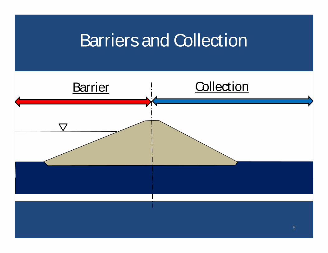
Barriers and Collection
Barrier Collection
5
• Can construct remediation whereseepage has been observed
• Often can directly observe placement ofall elements of construction
• May require reservoir lowering• May require dewatering
Some Collection and ControlConsiderations
6
Seepage does not threaten dam safety, . . . .when it is directed to through a filtered exit.
Some Collection and ControlConsiderations
7
Regarding the idea of designing dams forcontrolled under seepage, without filters –
I consider we have gotten scared out ofdoing this.
Effective filters are critical to success of seepagecollection and control alternatives.
1 “Closing Keypoints”, Presentation to Bureau of Reclamation, SeminalPaper Series, Unpublished, 1985.
R.B. Peck, lecture, 19851
8
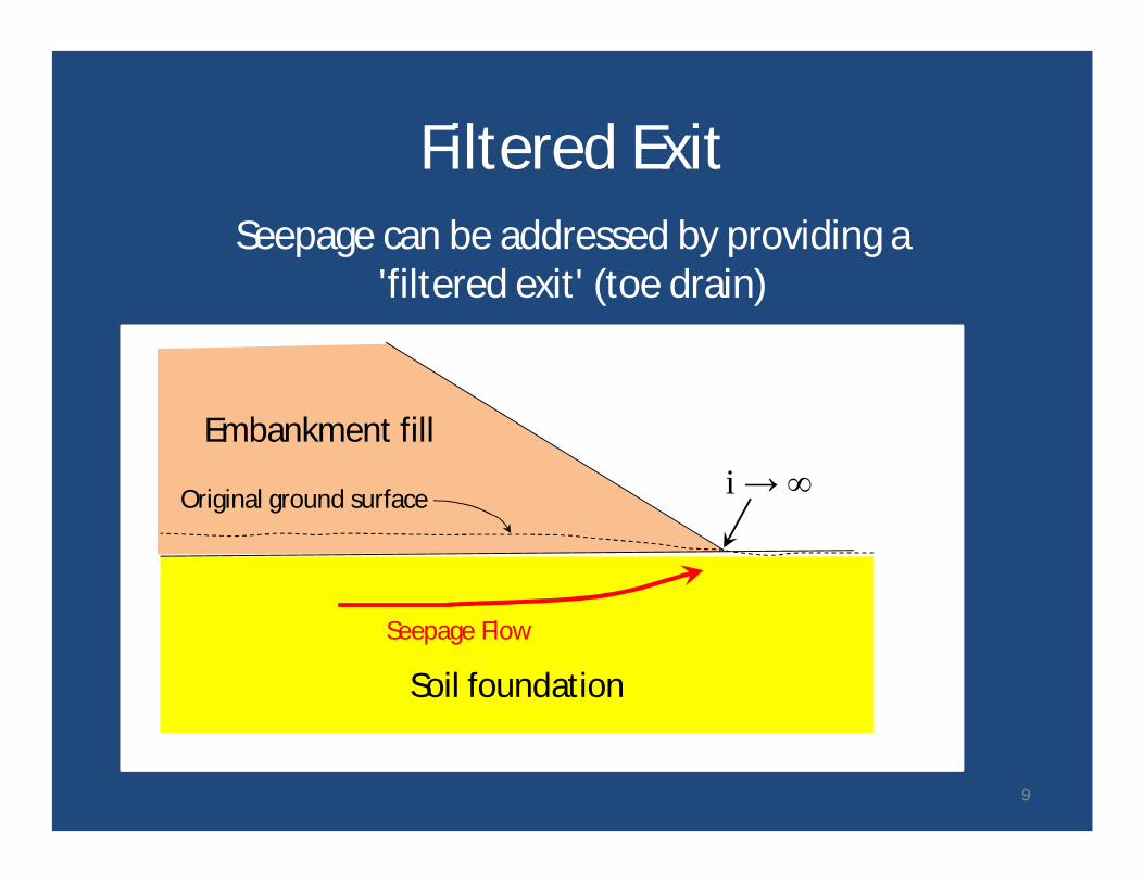
Embankment filli → ∞Original ground surface
Soil foundation
Seepage Flow
Seepage can be addressed by providing a'filtered exit' (toe drain)
Filtered Exit
9
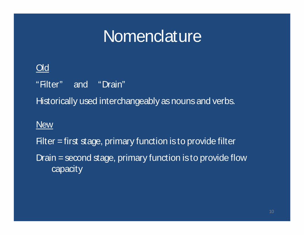
Nomenclature
Old
“Filter” and “Drain”
Historically used interchangeably as nouns and verbs.
New
Filter = first stage, primary function is to provide filter
Drain = second stage, primary function is to provide flowcapacity
10
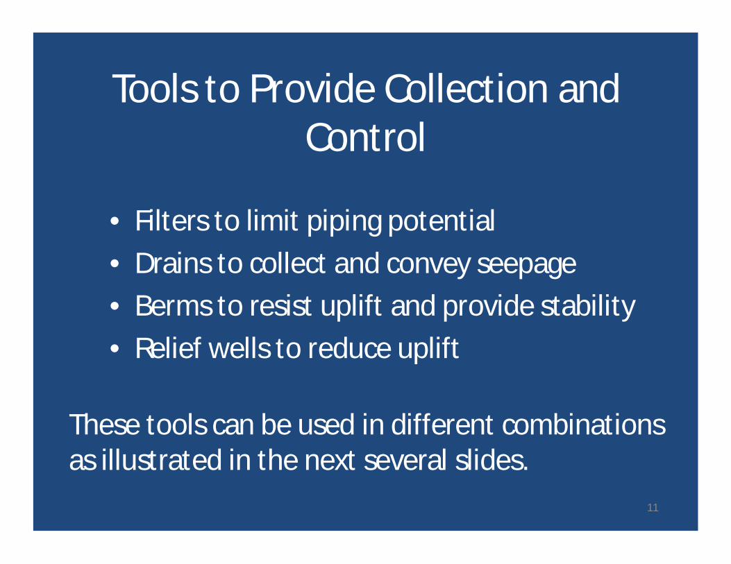
• Filters to limit piping potential• Drains to collect and convey seepage• Berms to resist uplift and provide stability• Relief wells to reduce uplift
Tools to Provide Collection andControl
These tools can be used in different combinationsas illustrated in the next several slides.
11
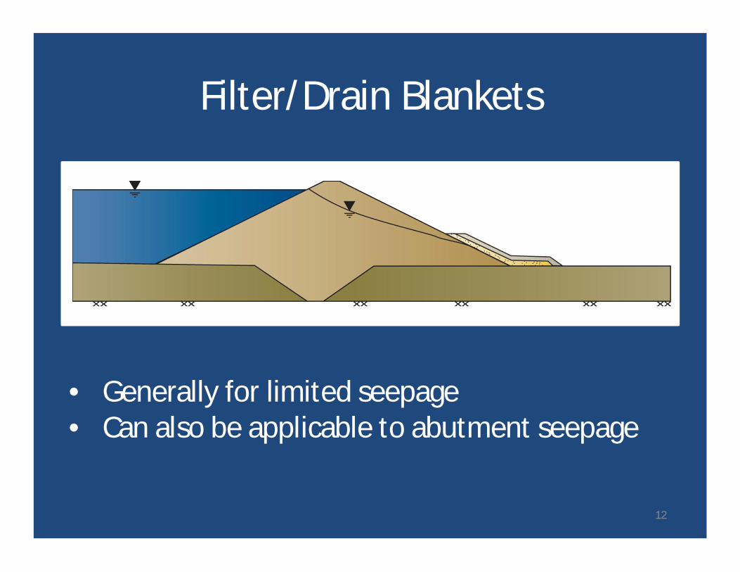
Filter/Drain Blankets
• Generally for limited seepage• Can also be applicable to abutment seepage
12
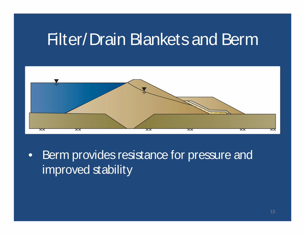
Filter/Drain Blankets and Berm
• Berm provides resistance for pressure andimproved stability
13
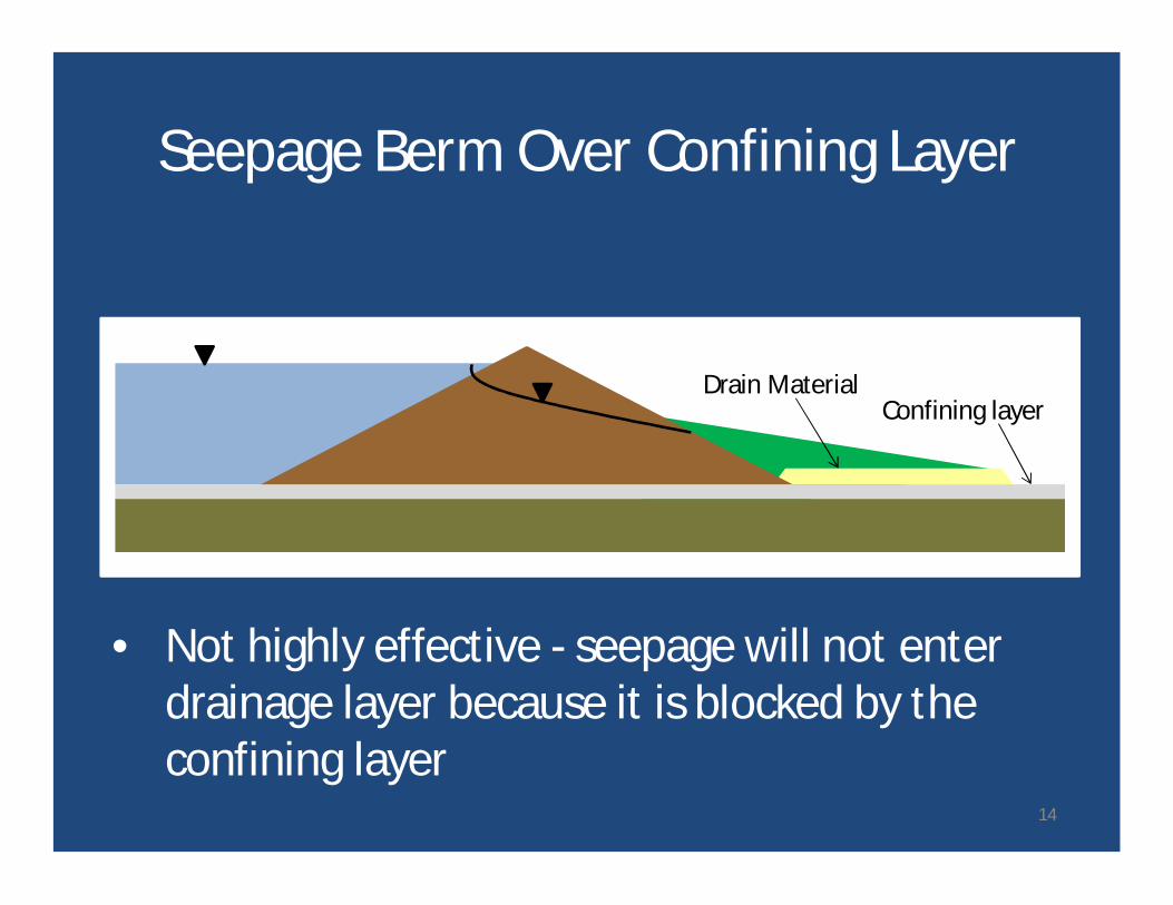
Seepage Berm Over Confining Layer
• Not highly effective - seepage will not enterdrainage layer because it is blocked by theconfining layer
Confining layerDrain Material
14
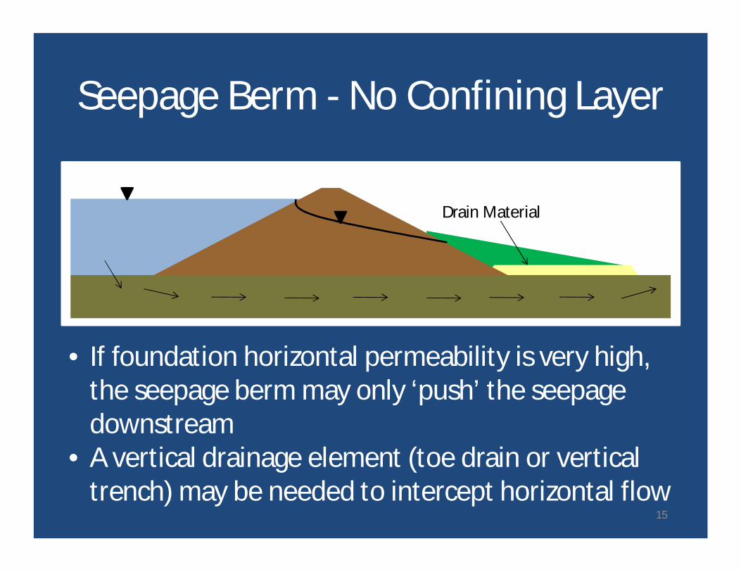
Seepage Berm - No Confining Layer
• If foundation horizontal permeability is very high,the seepage berm may only ‘push’ the seepagedownstream
• A vertical drainage element (toe drain or verticaltrench) may be needed to intercept horizontal flow
Drain Material
15
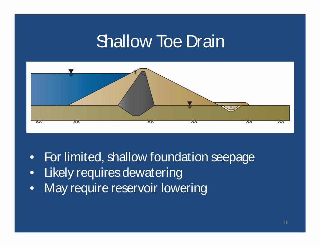
Shallow Toe Drain
• For limited, shallow foundation seepage• Likely requires dewatering• May require reservoir lowering
16
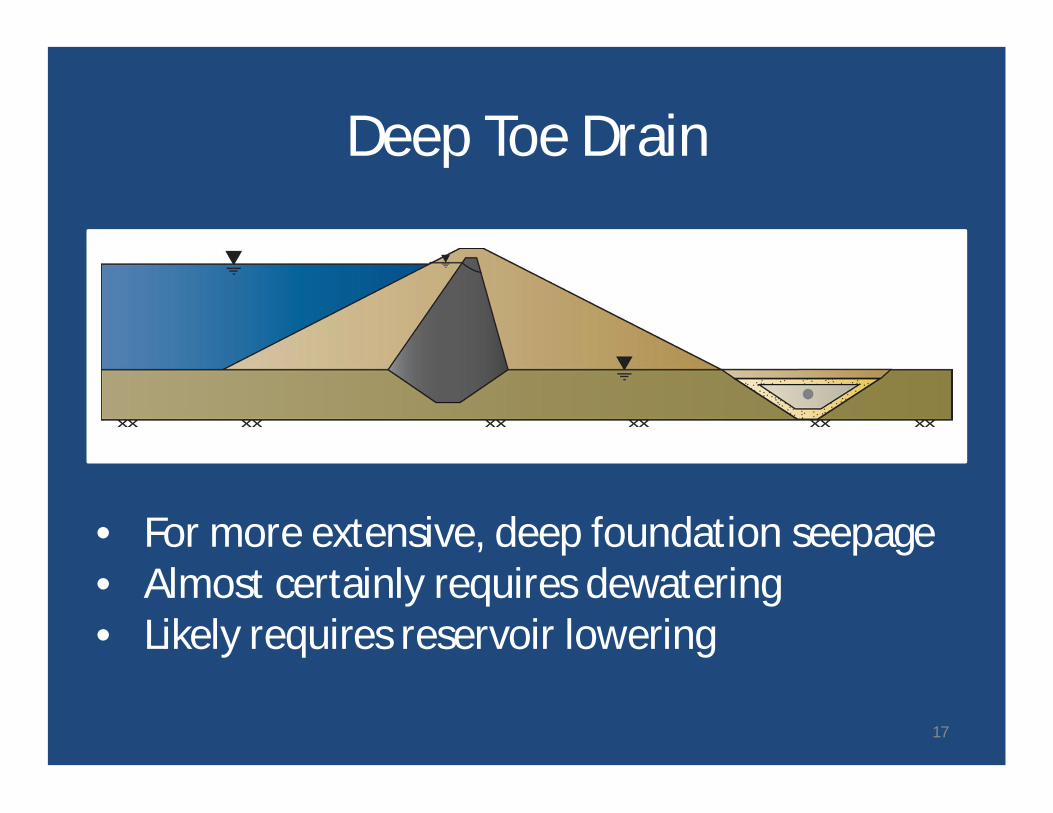
Deep Toe Drain
• For more extensive, deep foundation seepage• Almost certainly requires dewatering• Likely requires reservoir lowering
17
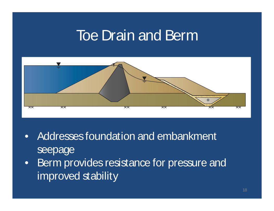
Toe Drain and Berm
• Addresses foundation and embankmentseepage
• Berm provides resistance for pressure andimproved stability
18
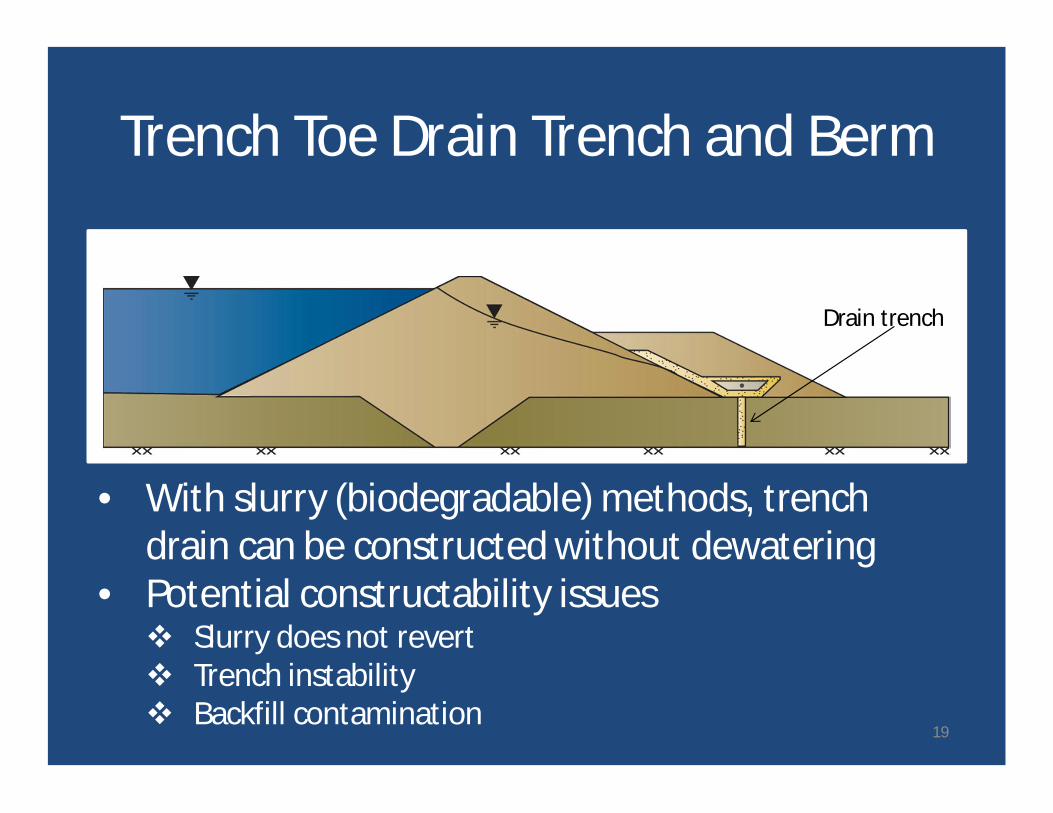
Trench Toe Drain Trench and Berm
Drain trench
• With slurry (biodegradable) methods, trenchdrain can be constructed without dewatering
• Potential constructability issuesv Slurry does not revertv Trench instabilityv Backfill contamination
19
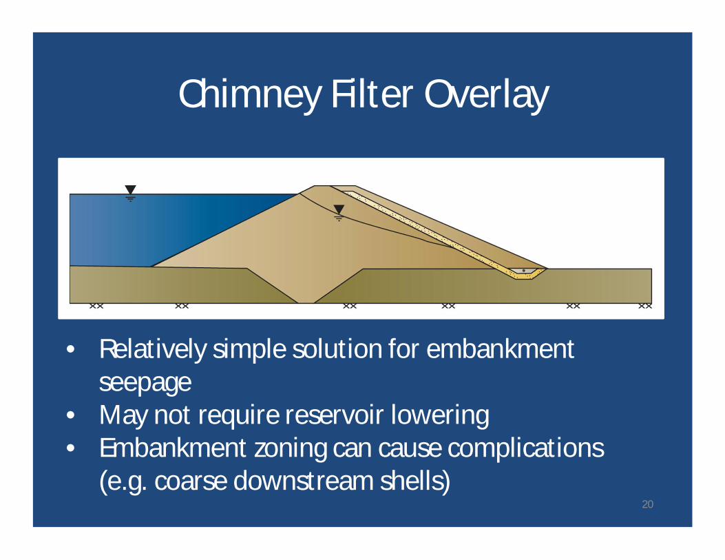
Chimney Filter Overlay
• Relatively simple solution for embankmentseepage
• May not require reservoir lowering• Embankment zoning can cause complications
(e.g. coarse downstream shells)20

Internal Chimney FilterShell: Coarse Rockfill
Core: Silt / Clay
• Comprehensive embankment solution• Construction risks need to be addressed• Reservoir lowering almost certainly required
21
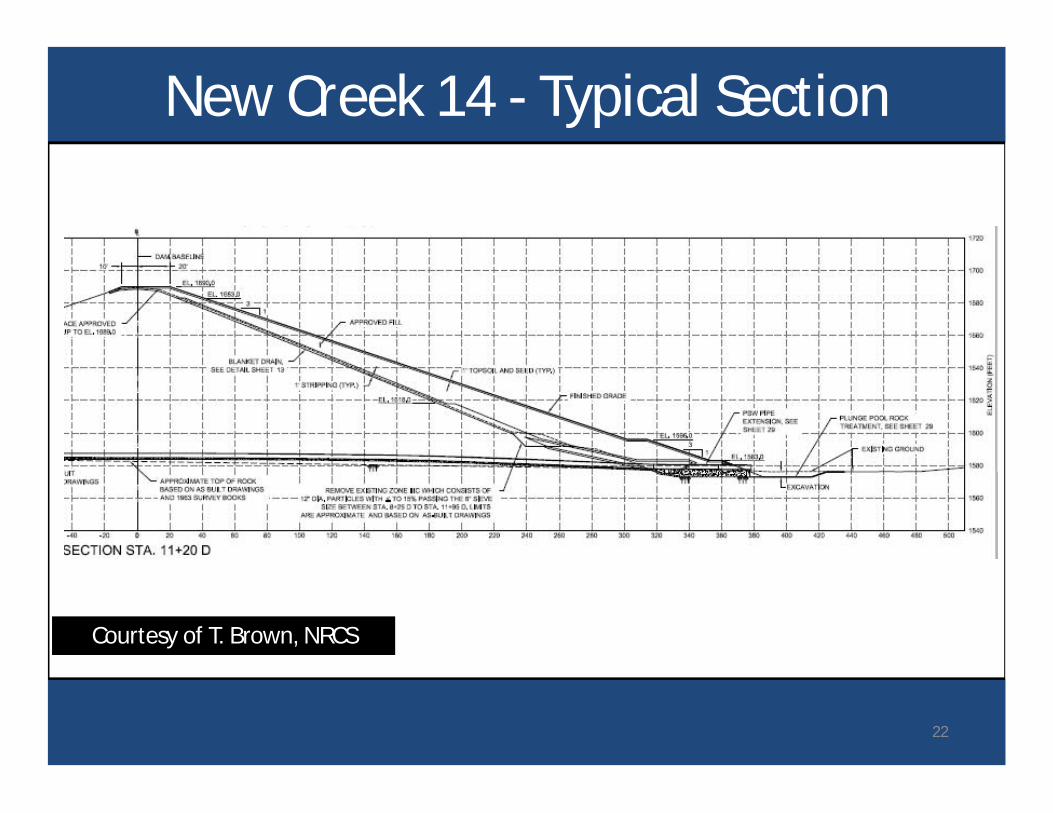
New Creek 14 - Typical Section
Courtesy of T. Brown, NRCS
22
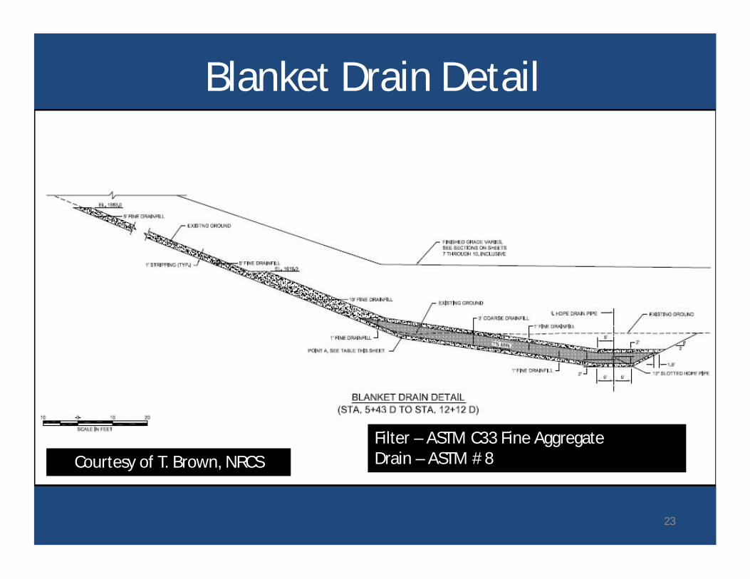
Blanket Drain Detail
Filter – ASTM C33 Fine AggregateDrain – ASTM # 8Courtesy of T. Brown, NRCS
23
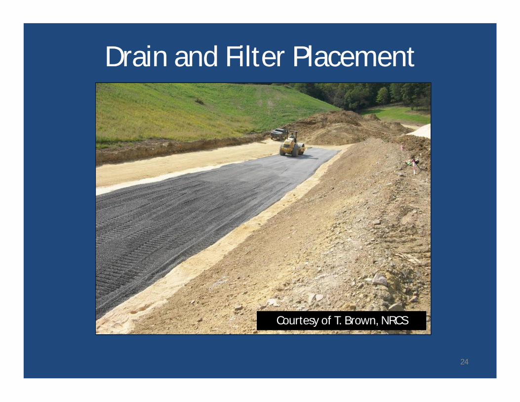
Drain and Filter Placement
Courtesy of T. Brown, NRCS
24
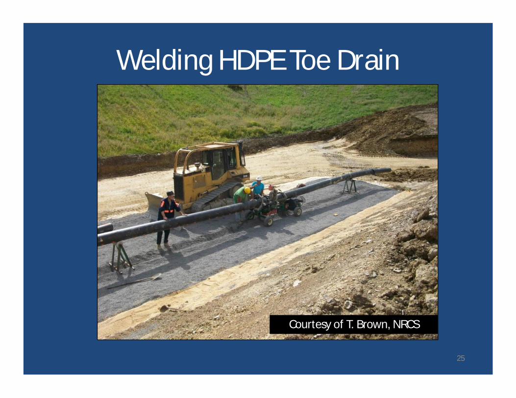
Welding HDPE Toe Drain
Courtesy of T. Brown, NRCS
25
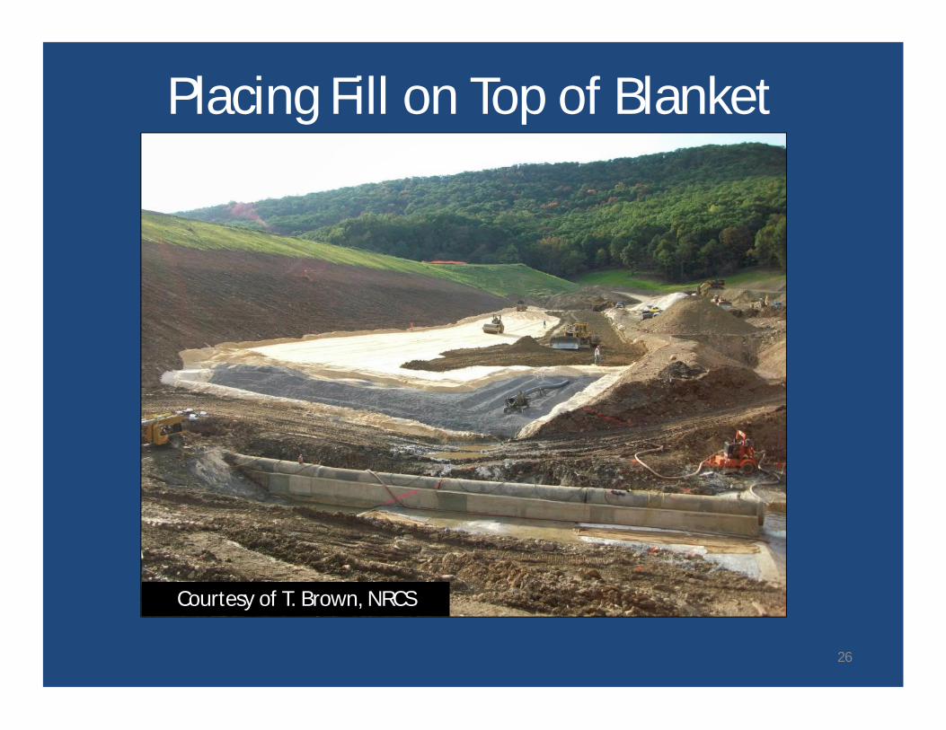
Placing Fill on Top of Blanket
Courtesy of T. Brown, NRCS
26
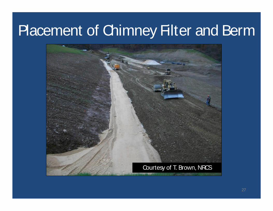
Placement of Chimney Filter and Berm
Courtesy of T. Brown, NRCS
27
Benefits of Chimney Filters
• Provide protection against internal erosionthrough defects
• Lower phreatic surface− Preventing breakout of seepage on downstream
face
− Increasing stability of downstream slope
28
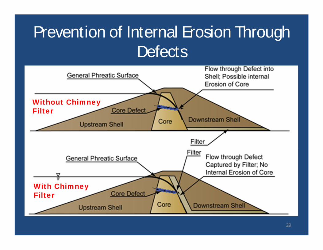
Prevention of Internal Erosion ThroughDefects
Without ChimneyFilter
With ChimneyFilter
29
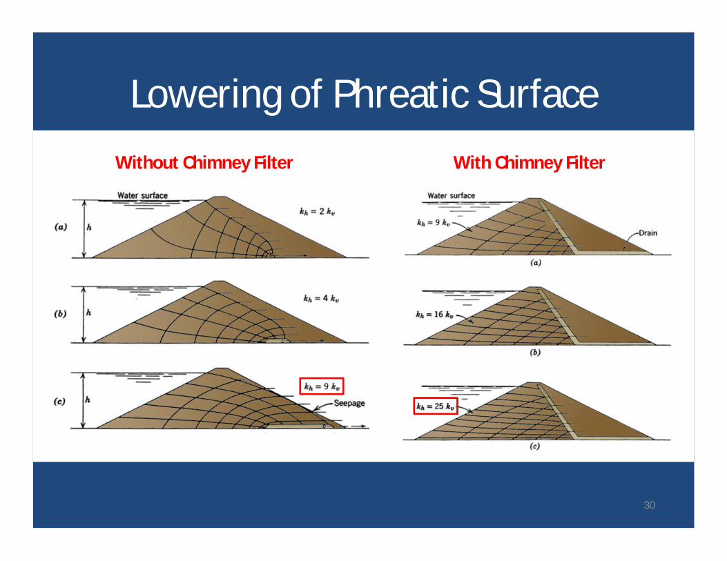
Lowering of Phreatic SurfaceWithout Chimney Filter With Chimney Filter
30
Top Elevation for Chimney Filter
• Historic practice – top of estimatedphreatic surface
• Current practice− Top of maximum normal pool as a minimum
− Often top of maximum flood pool or damcrest
31

• P. 5. I believe there is already sufficientevidence from dam behavior, supported bytheory, to require the designer to assume thatsmall concentrated leaks can develop throughthe impervious section of most embankmentdams, even those without exceptionaldifferential settlement.1 “Debatable Trends in Embankment Engineering,” Presentation to the A.S.C.E.National Capital Section Geotechnical Committee, Seminar on Lessons Learnedfrom Geotechnical Failures, February 3, 1984.
J.L. Sherard, lecture, 19841
32
Two-stage:• Provides capacity to handle large
flow• Addresses potential negative effects
of filter contamination
One-Stage vs. Two-Stage Chimneys
33
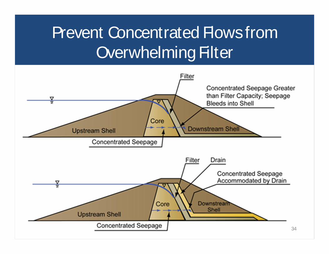
Prevent Concentrated Flows fromOverwhelming Filter
34
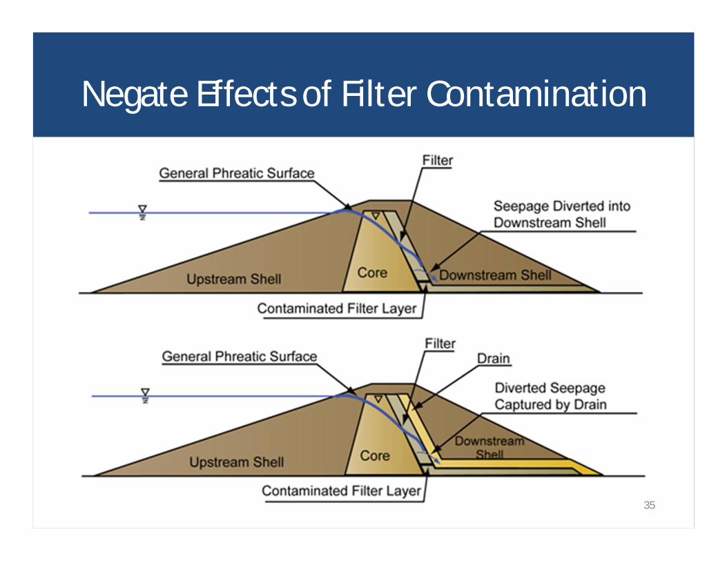
Negate Effects of Filter Contamination
35
• Relieve pore pressures and lowerpiezometric surface within confined perviousfoundation strata
• Reduce uplift and improve stability• Control exit gradients and reduce piping
potential• Maintenance required• Possible limitation of radius of influence• Drain trench may be better alternative
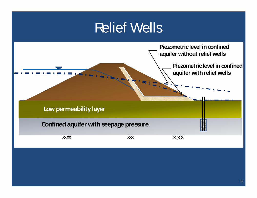
Relief Wells
36
37
Low permeability layer
Confined aquifer with seepage pressure
xx xx xxx xxx
Relief WellsPiezometric level in confinedaquifer without relief wells
Piezometric level in confinedaquifer with relief wells
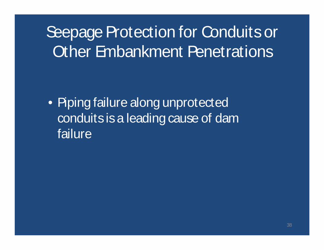
• Piping failure along unprotectedconduits is a leading cause of damfailure
Seepage Protection for Conduits orOther Embankment Penetrations
38
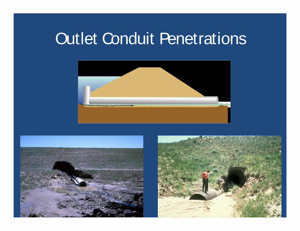
Outlet Conduit Penetrations
39
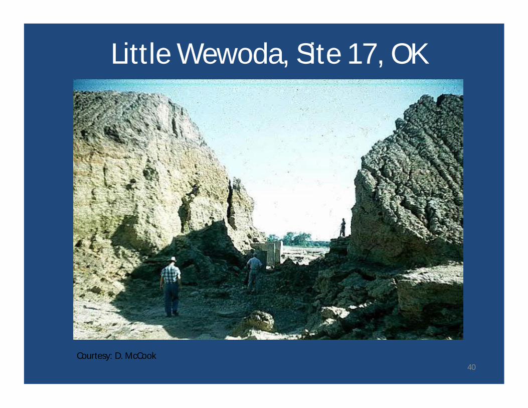
Courtesy: D. McCook
Little Wewoda, Site 17, OK
40
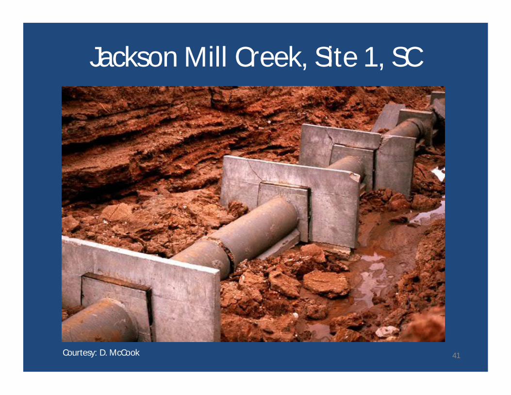
Courtesy: D. McCook
Jackson Mill Creek, Site 1, SC
41
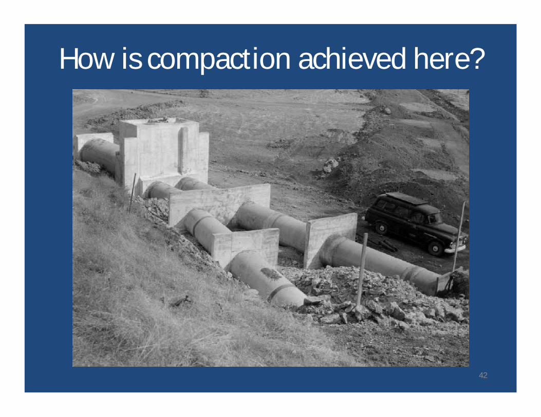
How is compaction achieved here?
42
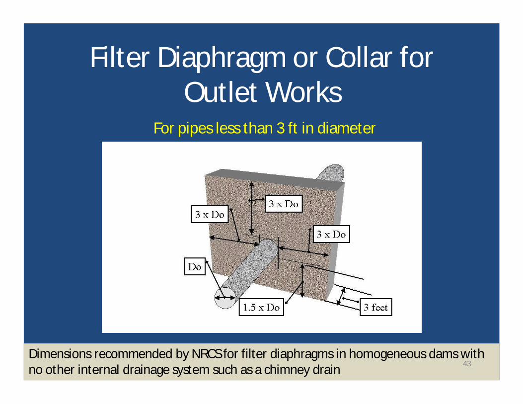
Dimensions recommended by NRCS for filter diaphragms in homogeneous dams withno other internal drainage system such as a chimney drain
Filter Diaphragm or Collar forOutlet Works
For pipes less than 3 ft in diameter
43
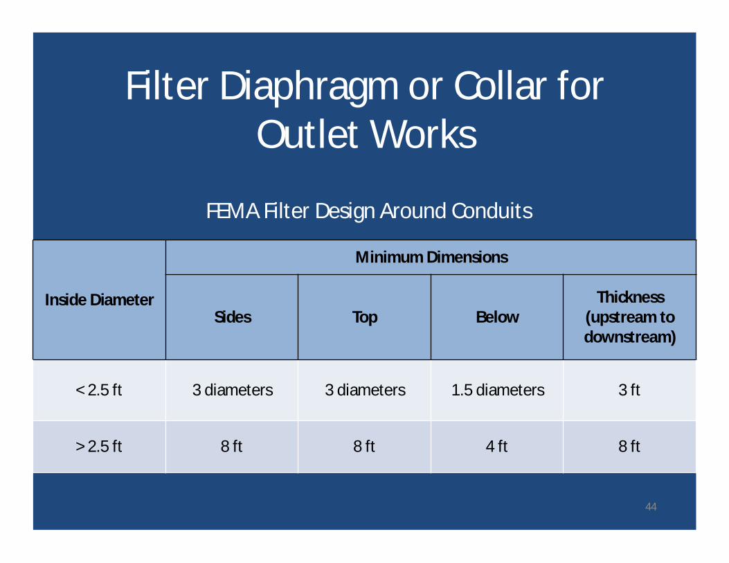
Filter Diaphragm or Collar forOutlet Works
Inside Diameter
Minimum Dimensions
Sides Top BelowThickness
(upstream todownstream)
< 2.5 ft 3 diameters 3 diameters 1.5 diameters 3 ft
> 2.5 ft 8 ft 8 ft 4 ft 8 ft
FEMA Filter Design Around Conduits
44
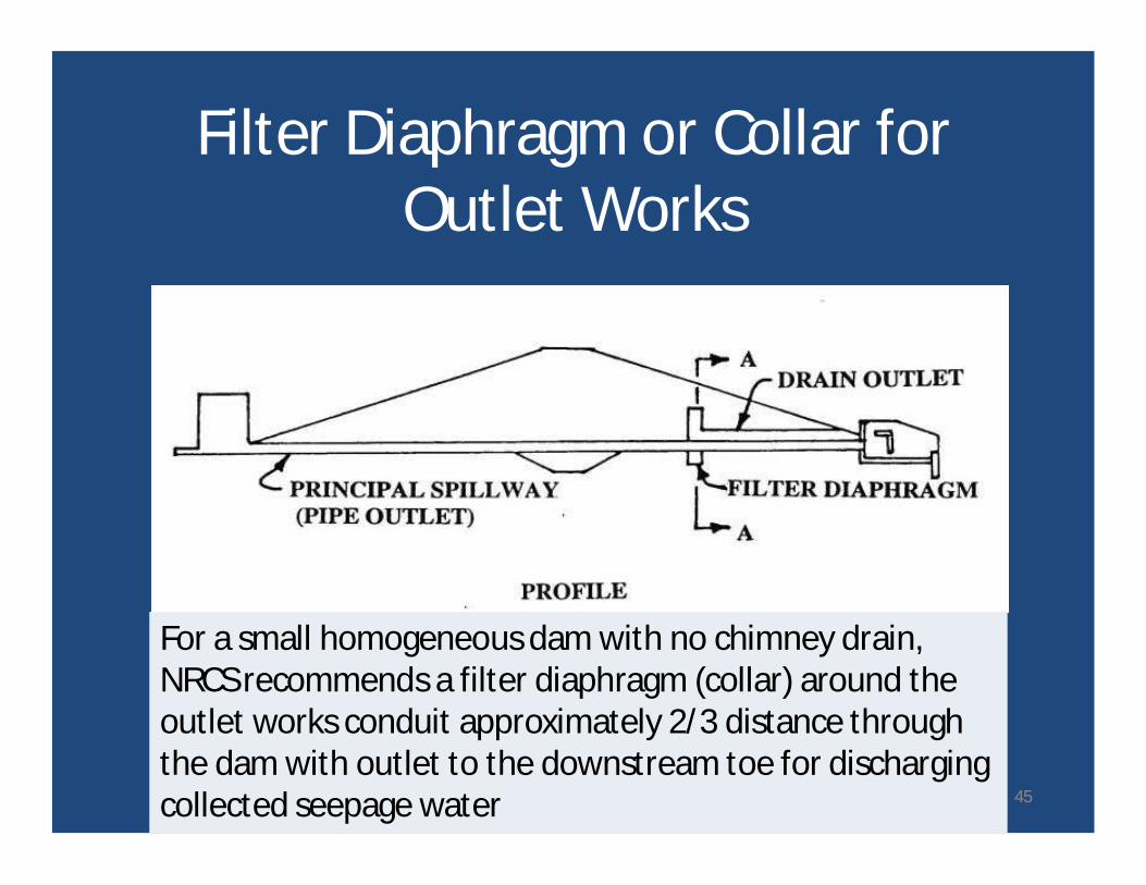
For a small homogeneous dam with no chimney drain,NRCS recommends a filter diaphragm (collar) around theoutlet works conduit approximately 2/3 distance throughthe dam with outlet to the downstream toe for dischargingcollected seepage water
Filter Diaphragm or Collar forOutlet Works
45
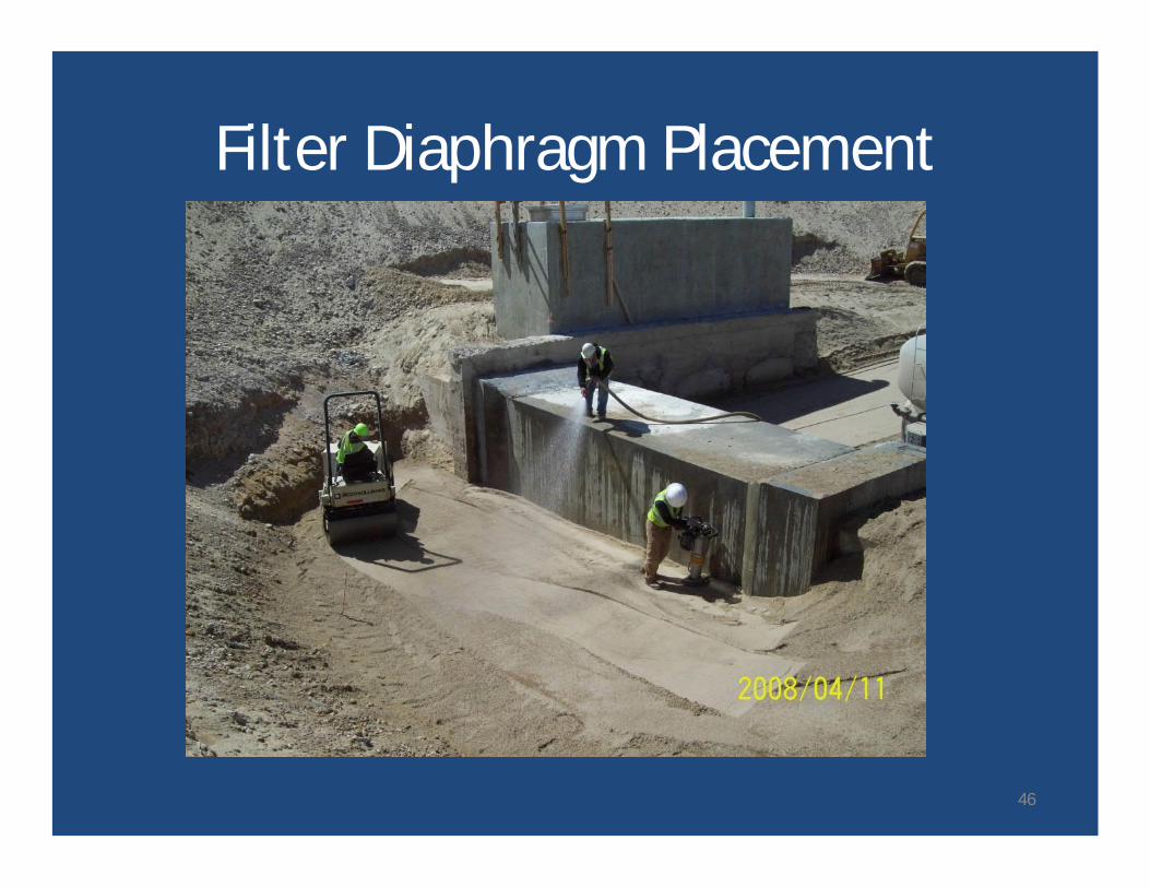
Filter Diaphragm Placement
46

If the outlet works is located in a trench below the foundation level, thefilter diaphragm should extend a short distance into the slopes of theexcavation to intercept seepage that may follow the contact betweenearthfill and the natural foundation soil
Filter Diaphragm for Outlet Works
47
• Natural vs. processed materials• Use of standard gradations• Drain pipe gravel envelopes• Geotextiles
Some Practicalities
48
• Rare to find natural soils suitable for filters– Not “clean” enough– Can be gap graded– Gradations can vary significantly within the
deposit– Can contain excessive coarse particles -
segregation• Readily available ASTM C33 fine aggregate is
an excellent filter in almost all cases
Natural vs. Processed Materials
49
• Suitable for most base soils• Readily available• Similar gradations can be used, if available at
less cost• Not suitable for some clays and silts (some
Category 1 base soils) – soils with more than85% finer than about 0.045 mm
ASTM C33 Fine Aggregate
50
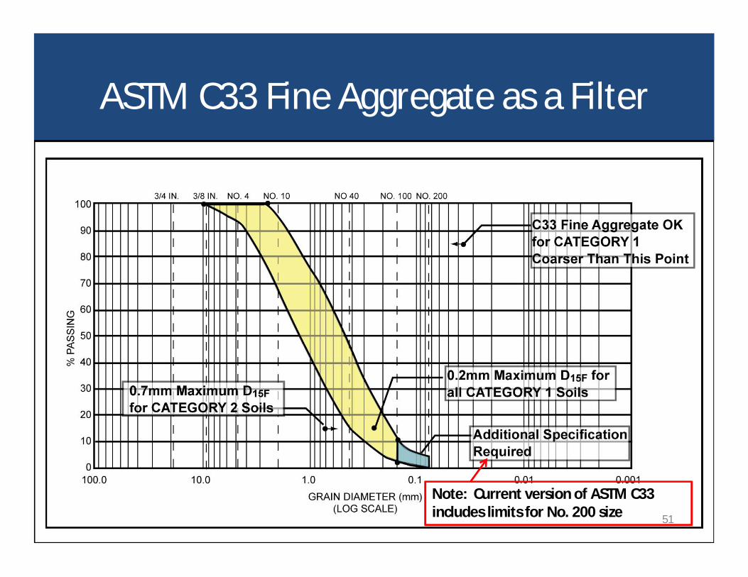
ASTM C33 Fine Aggregate as a Filter
Note: Current version of ASTM C33includes limits for No. 200 size 51
• Recommend <2 to 3% in stockpile and <5% inplace
• Some breakdown should be expected• Permeability decreases dramatically with fines
contents greater than 5%
Fines Contents for Filters andDrains
52
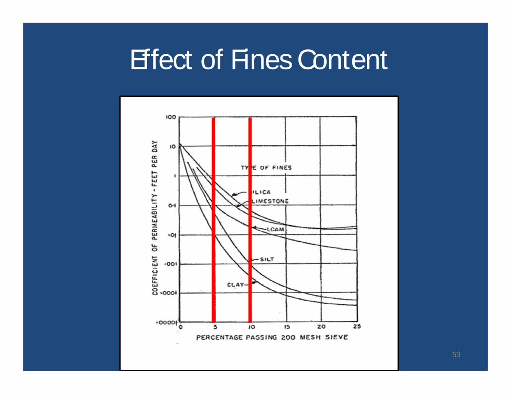
Effect of Fines Content
After Barber and Sawyer, 1952 53
• Economical for small quantities• Specify locally available sand and gravel
materials that fall within the latitude of thefilter requirements
• Potential sources:– State DOT specifications– AASHTO gradations– ASTM gradations– Products of local aggregate producers
• Verify local availability• Avoid cohesive fines
Standard Gradations
54
• Slotted pipes embedded in filter sand oftenbecome plugged
• Full pipe capacity is not realized
Gravel Envelopes Around DrainPipes
55
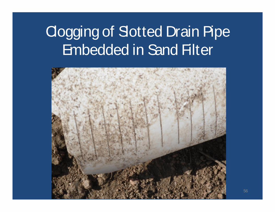
Clogging of Slotted Drain PipeEmbedded in Sand Filter
56
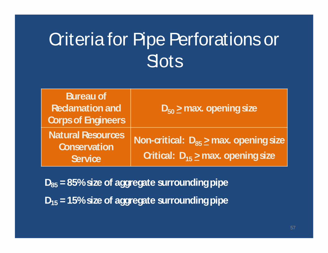
Criteria for Pipe Perforations orSlots
D85 = 85% size of aggregate surrounding pipe
D15 = 15% size of aggregate surrounding pipe
Bureau ofReclamation and
Corps of EngineersD50 > max. opening size
Natural ResourcesConservation
Service
Non-critical: D85 > max. opening sizeCritical: D15 > max. opening size
57
• Slots are preferred – less chance of clogging• Not that important – either should work if sized
correctly
Slots or Holes
58
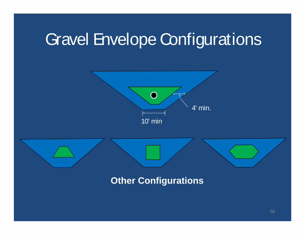
4' min.
10' min.
Gravel Envelope Configurations
Other Configurations
59
Pipe SizePipe size is controlled by the most stringent ofthe following criteria:
• Minimum inner diameter− This requirement is for access for future camera
inspection
• Estimated maximum flow rate should not exceed aflow depth of 75% of the pipe height.− This requirement is to account for post construction
sags in the pipe alignment due to differentialsettlement.
− Pipes should not flow full or be pressurized.60
• Susceptible to installation damage• May clog or deteriorate• Use in critical locations not allowed by
USACE and Reclamation• Published position of the NDSRB:
– “It is the policy of the National Dam Safety ReviewBoard that geotextiles should not be used inlocations that are critical to the safety of the dam.” 1
Geotextiles
1 Geotextiles in Embankment Dams, Status Report on the Use of Geotextiles inEmbankment Dam Construction and Rehabilitation, FEMA, 2008
61
Seepage “Cut Off” Methods
• Grouting• Low Permeability Blankets• Barrier Walls
Note: Cut off is in quotes, because it is verydifficult to truly cut off seepage – seepagereduction or seepage barriers may be betterterms.
62
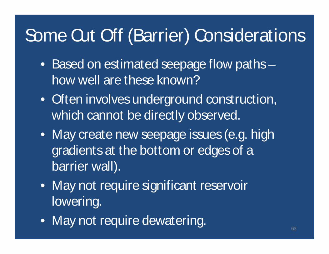
• Based on estimated seepage flow paths –how well are these known?
• Often involves underground construction,which cannot be directly observed.
• May create new seepage issues (e.g. highgradients at the bottom or edges of abarrier wall).
• May not require significant reservoirlowering.
• May not require dewatering.
Some Cut Off (Barrier) Considerations
63
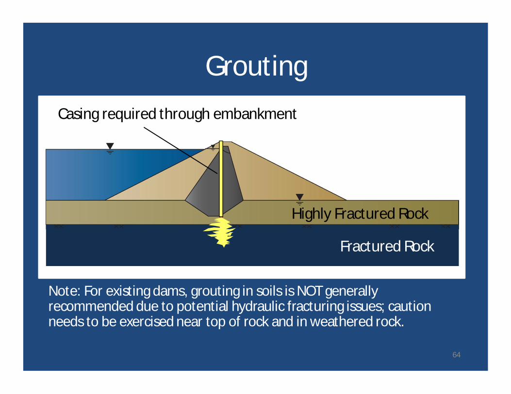
Grouting
Note: For existing dams, grouting in soils is NOT generallyrecommended due to potential hydraulic fracturing issues; cautionneeds to be exercised near top of rock and in weathered rock.
Casing required through embankment
Fractured Rock
Highly Fractured Rock
64

Grouting Cautions• Limited soils for which grouting is effective.• Soils (and soft rock) can be hydrofractured.• Current practice is multiple lines.• In rock, grout only penetrates water- and air-
filled features – potential future erosion ofremaining infilling.
• Grout may deteriorate over time.• Grouting is sometimes considered to be a
temporary solution.65
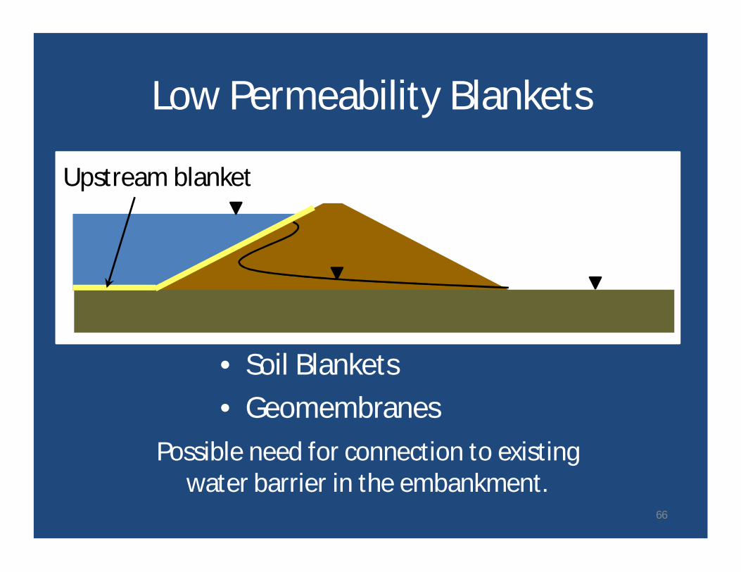
Low Permeability Blankets
• Soil Blankets• Geomembranes
Upstream blanket
Possible need for connection to existingwater barrier in the embankment.
66
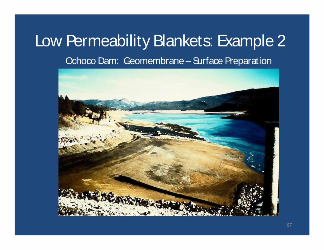
Low Permeability Blankets: Example 2Ochoco Dam: Geomembrane – Surface Preparation
67
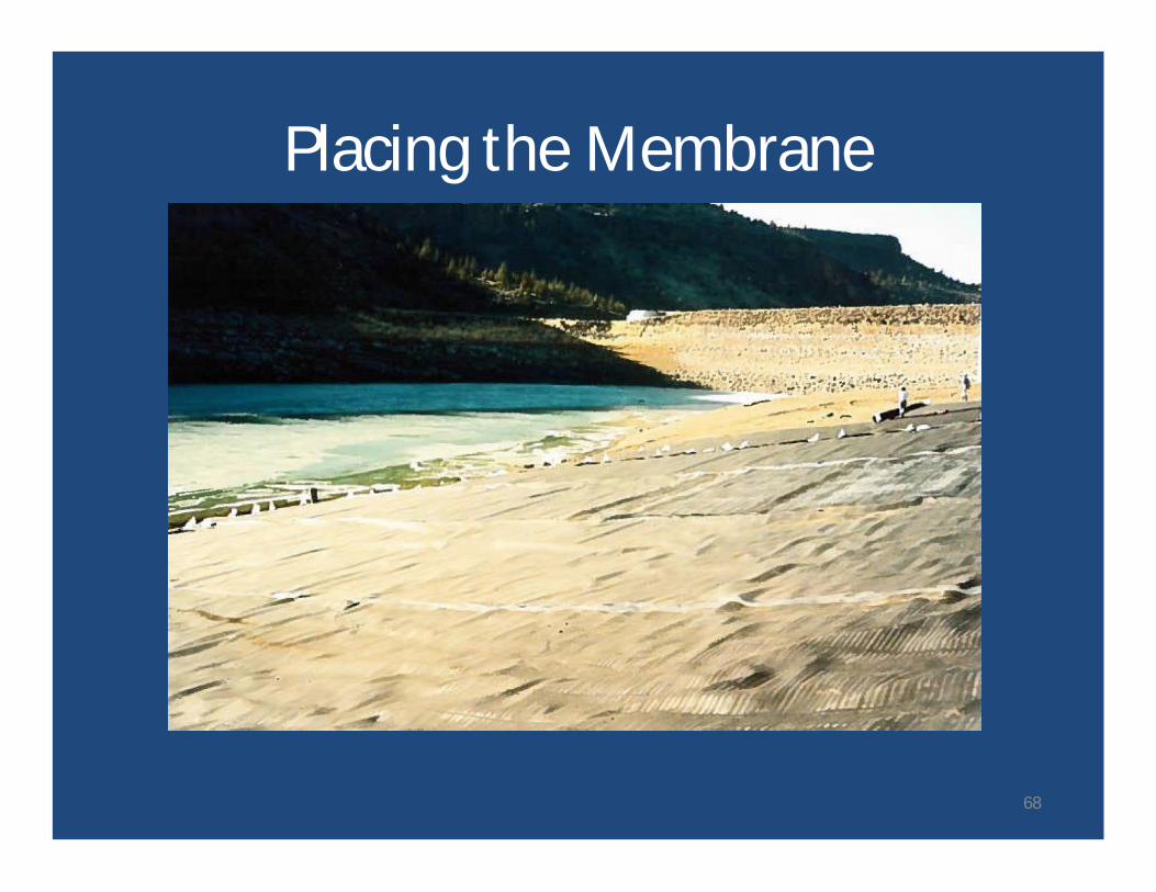
Placing the Membrane
Example - Ochoco Dam
68
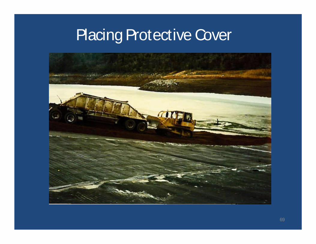
Placing Protective Cover
69
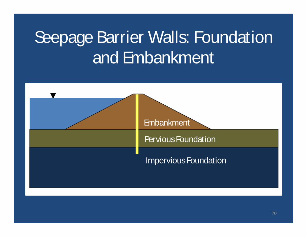
Seepage Barrier Walls: Foundationand Embankment
Pervious Foundation
Impervious Foundation
Embankment
70
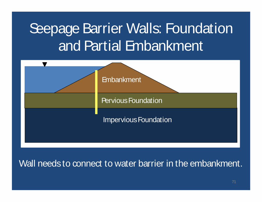
Seepage Barrier Walls: Foundationand Partial Embankment
Pervious Foundation
Impervious Foundation
Embankment
Wall needs to connect to water barrier in the embankment.
71
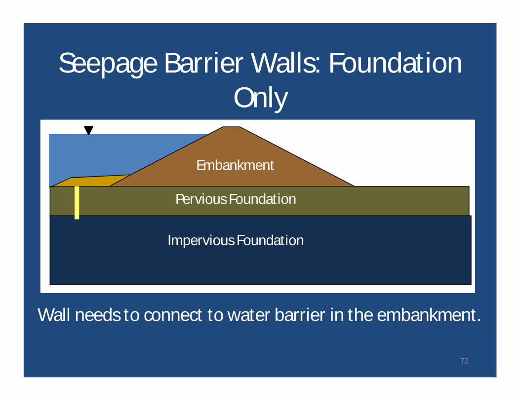
Seepage Barrier Walls: FoundationOnly
Pervious Foundation
Impervious Foundation
Embankment
Wall needs to connect to water barrier in the embankment.
72
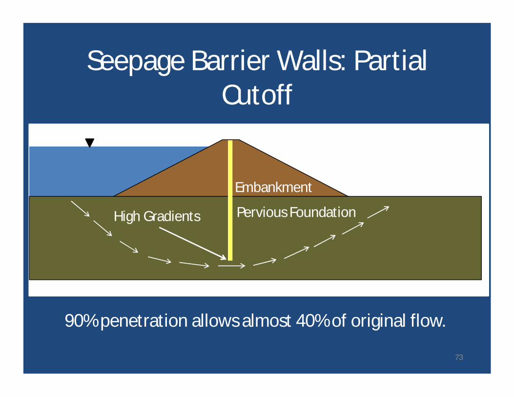
Seepage Barrier Walls: PartialCutoff
Pervious Foundation
Embankment
90% penetration allows almost 40% of original flow.
High Gradients
73
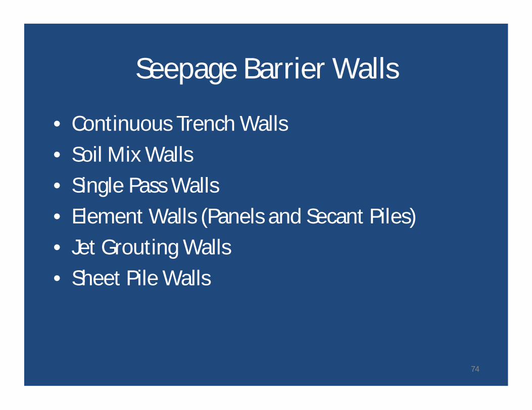
Seepage Barrier Walls
• Continuous Trench Walls• Soil Mix Walls• Single Pass Walls• Element Walls (Panels and Secant Piles)• Jet Grouting Walls• Sheet Pile Walls
74
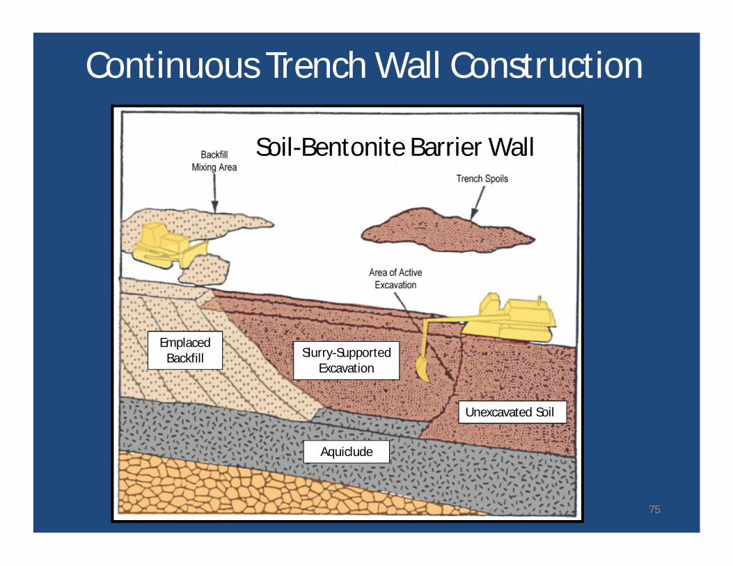
Continuous Trench Wall Construction
Soil-Bentonite Barrier Wall
EmplacedBackfill
Unexcavated Soil
Aquiclude
Slurry-SupportedExcavation
75
Continuous Trench Barrier Walls
Salient Features• Low Cost/Rapid Const.• Slurry Supported
Excavation• No Backfill Joints• Non-Structural• Low Permeability• Depth up to ~85 feet
with Backhoe
Typical Backfills
• Soil-Bentonite (SB)
• Cement-Bentonite(CB)
• Soil-Cement-Bentonite (SCB)
76
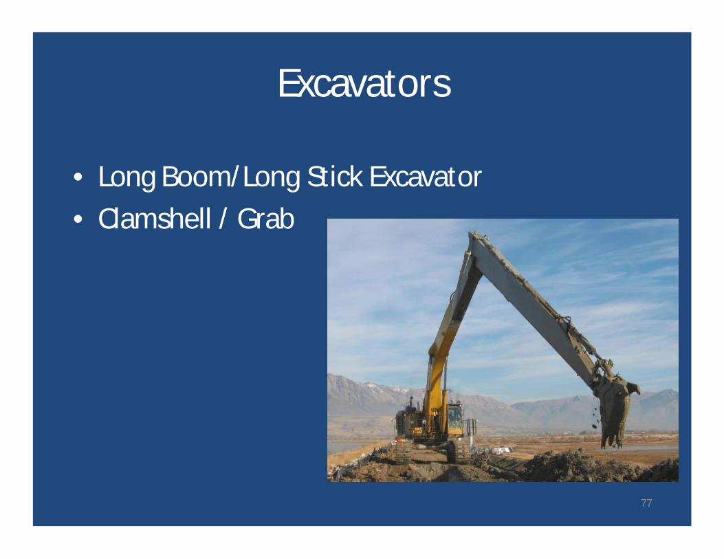
Excavators
• Long Boom/Long Stick Excavator• Clamshell / Grab
77
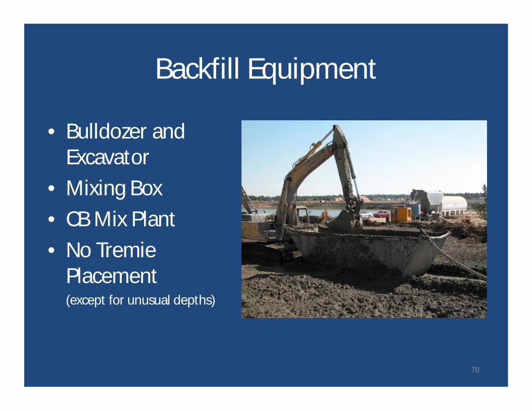
Backfill Equipment
• Bulldozer andExcavator
• Mixing Box• CB Mix Plant• No Tremie
Placement(except for unusual depths)
78
Keechelus Dam
• Modified in 2002 for seepage and internalerosion deficiencies.
• Soil-bentonite wall installed near right end ofdam as part of larger modifications.
• Foundation (alluvial fan) sand and graveldeposits.
• Soil amended with fines for 'soil' part of S-BWall.
79
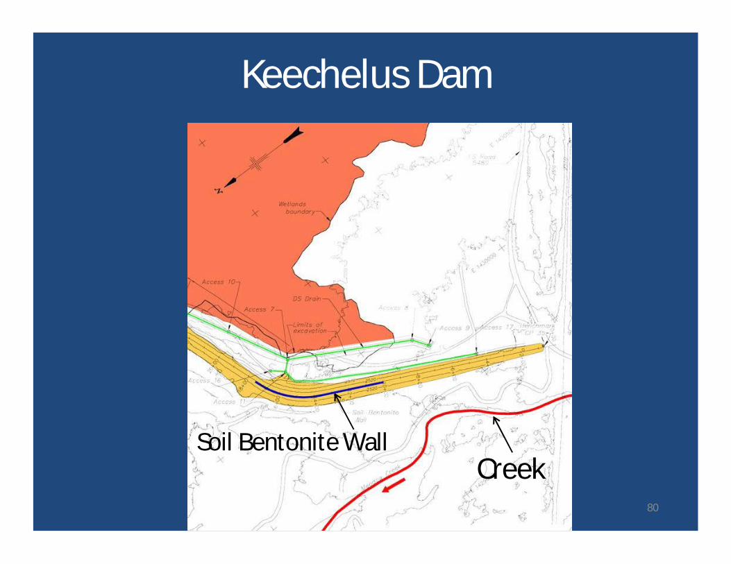
Soil Bentonite Wall
Keechelus Dam
Creek80
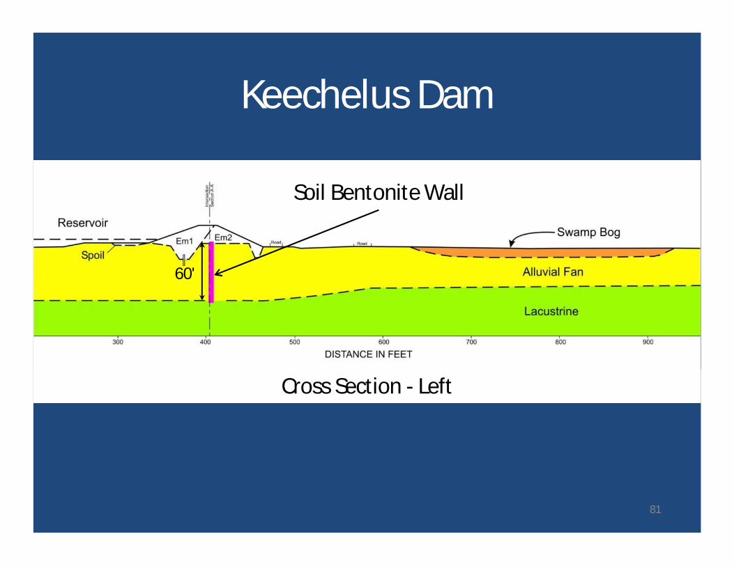
Cross Section - Left
Soil Bentonite Wall
60'
Keechelus Dam
81
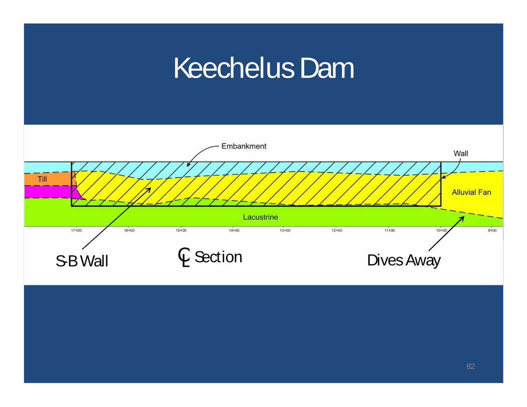
CL SectionS-B Wall Dives Away
Keechelus Dam
82
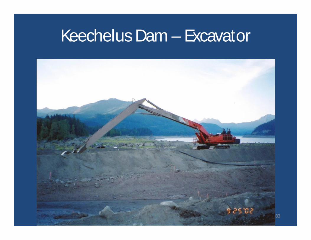
Keechelus Dam – Excavator
83
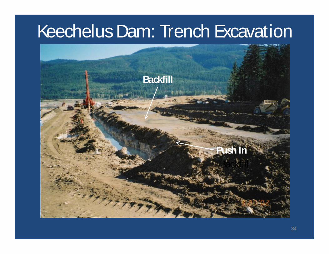
Keechelus Dam: Trench Excavation
BackfillPush In
Backfill
84
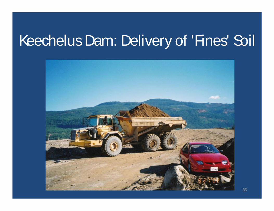
Keechelus Dam: Delivery of 'Fines' Soil
85
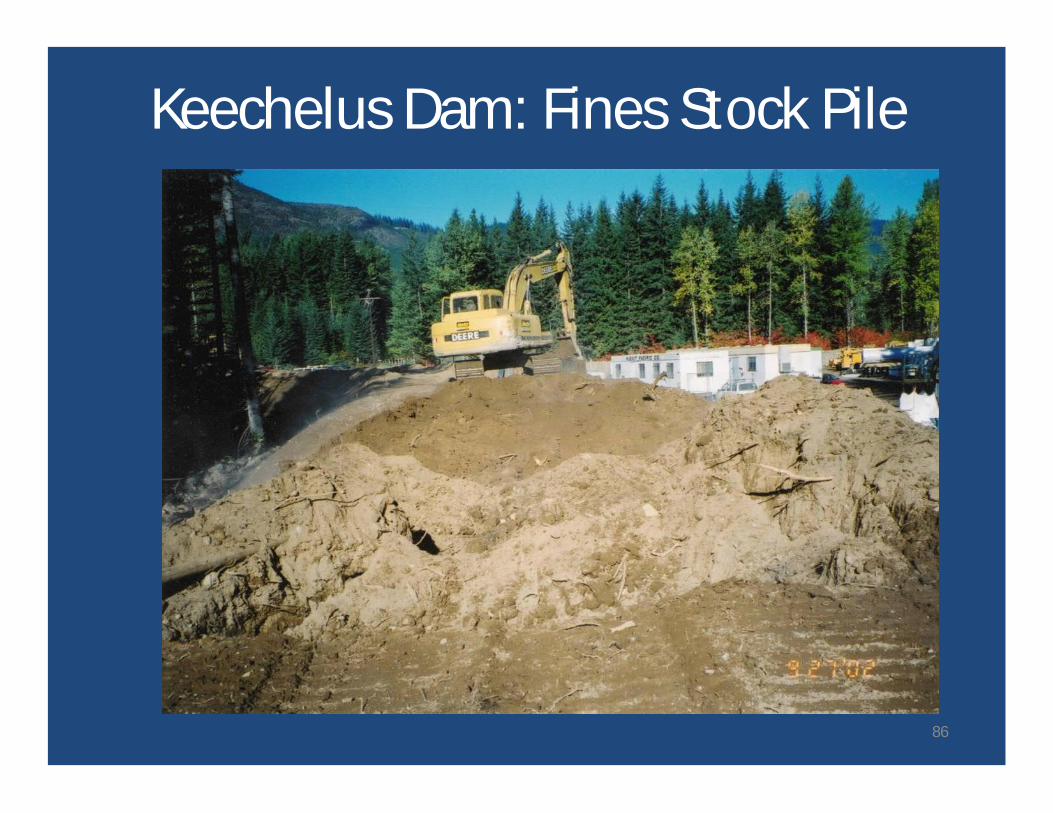
Keechelus Dam: Fines Stock Pile
86
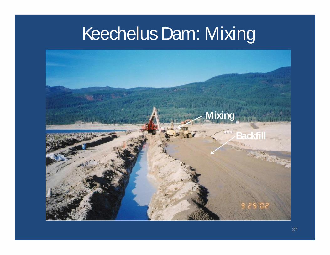
Keechelus Dam: Mixing
Mixing
Backfill
87
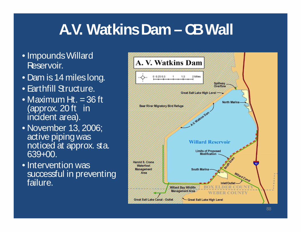
A.V. Watkins Dam – CB Wall
• Impounds WillardReservoir.
• Dam is 14 miles long.• Earthfill Structure.• Maximum Ht. = 36 ft
(approx. 20 ft inincident area).
• November 13, 2006;active piping wasnoticed at approx. sta.639+00.
• Intervention wassuccessful in preventingfailure.
88
89
90
91
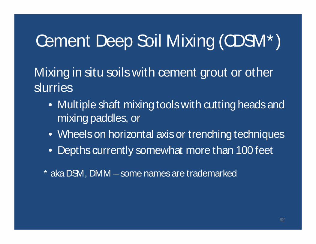
Cement Deep Soil Mixing (CDSM*)
Mixing in situ soils with cement grout or otherslurries
• Multiple shaft mixing tools with cutting heads andmixing paddles, or
• Wheels on horizontal axis or trenching techniques• Depths currently somewhat more than 100 feet
* aka DSM, DMM – some names are trademarked
92
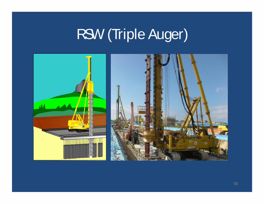
RSW (Triple Auger)
93
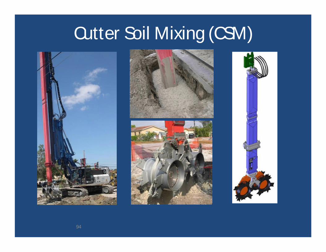
Cutter Soil Mixing (CSM)
94
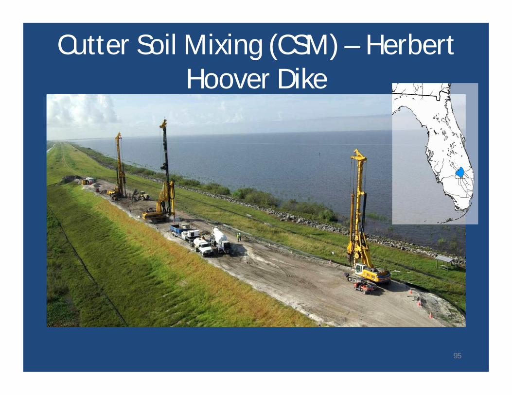
Cutter Soil Mixing (CSM) – HerbertHoover Dike
95
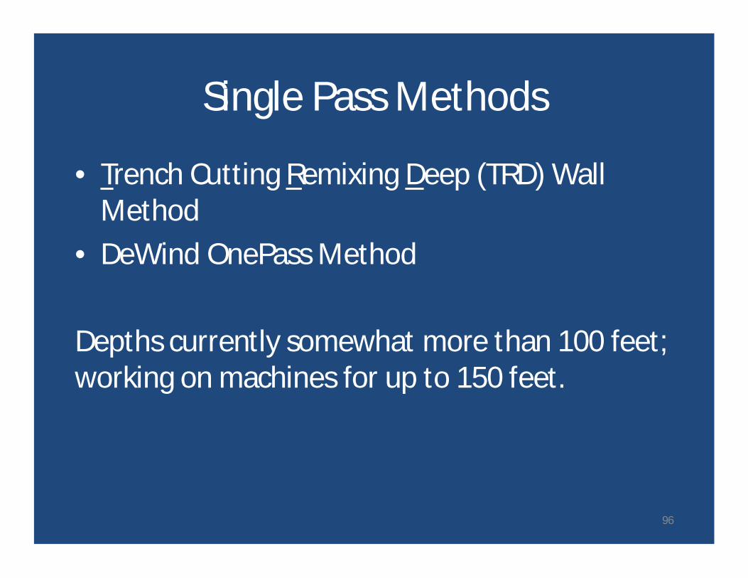
Single Pass Methods
• Trench Cutting Remixing Deep (TRD) WallMethod
• DeWind OnePass Method
Depths currently somewhat more than 100 feet;working on machines for up to 150 feet.
96
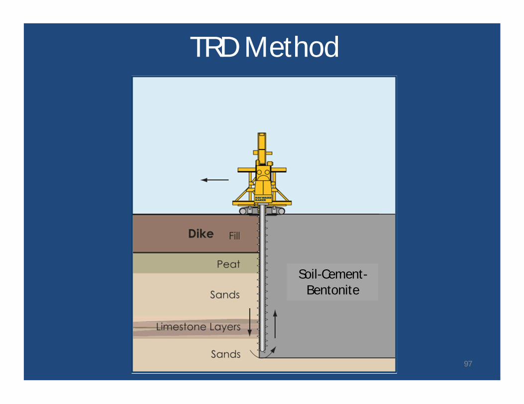
TRD Method
Soil-Cement-Bentonite
97
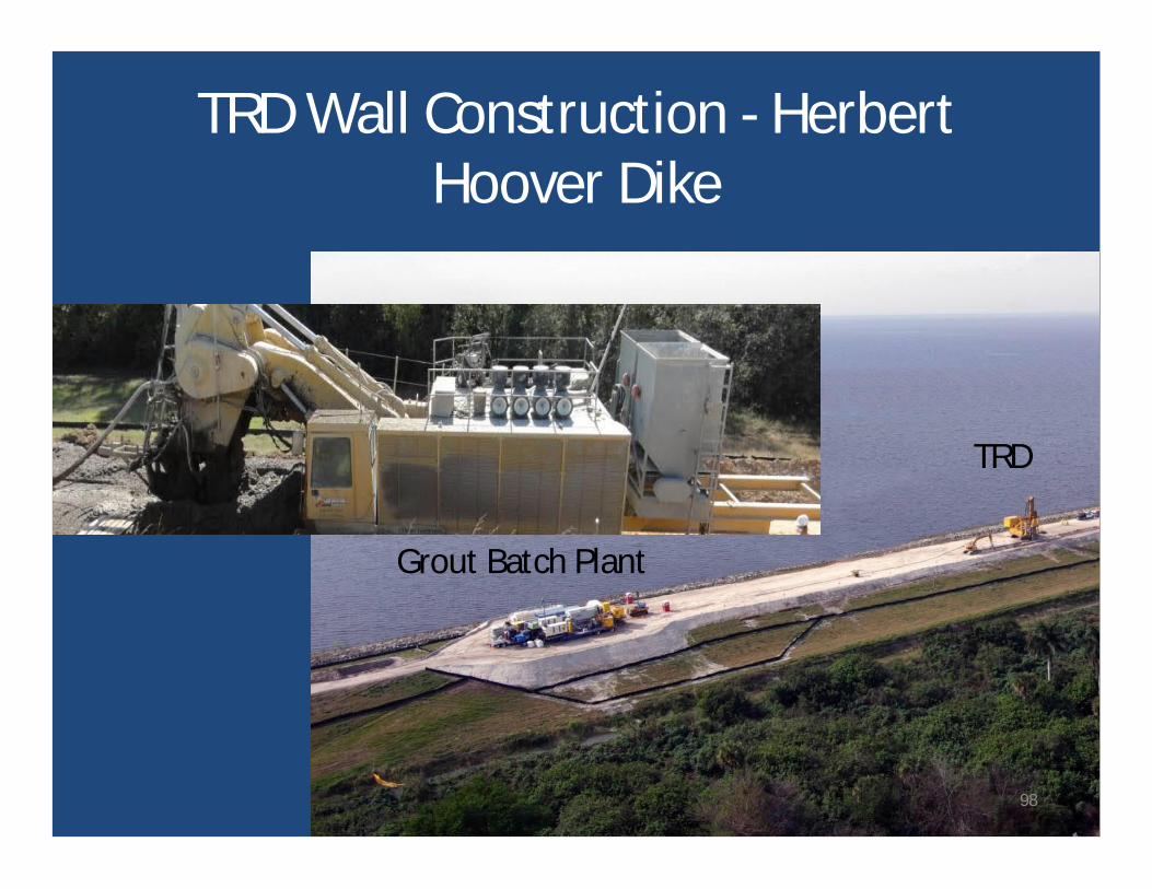
Grout Batch Plant
TRD
TRD Wall Construction - HerbertHoover Dike
98
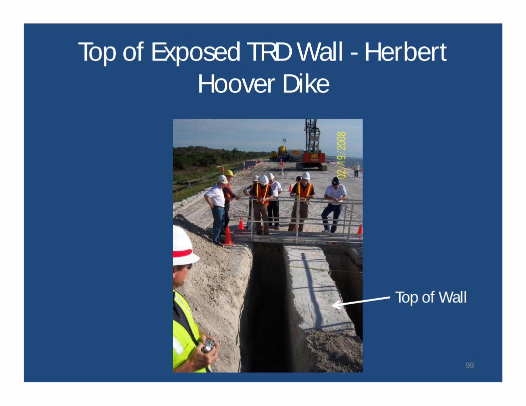
Top of Wall
Top of Exposed TRD Wall - HerbertHoover Dike
99
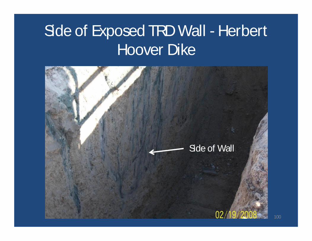
Side of Wall
Side of Exposed TRD Wall - HerbertHoover Dike
100
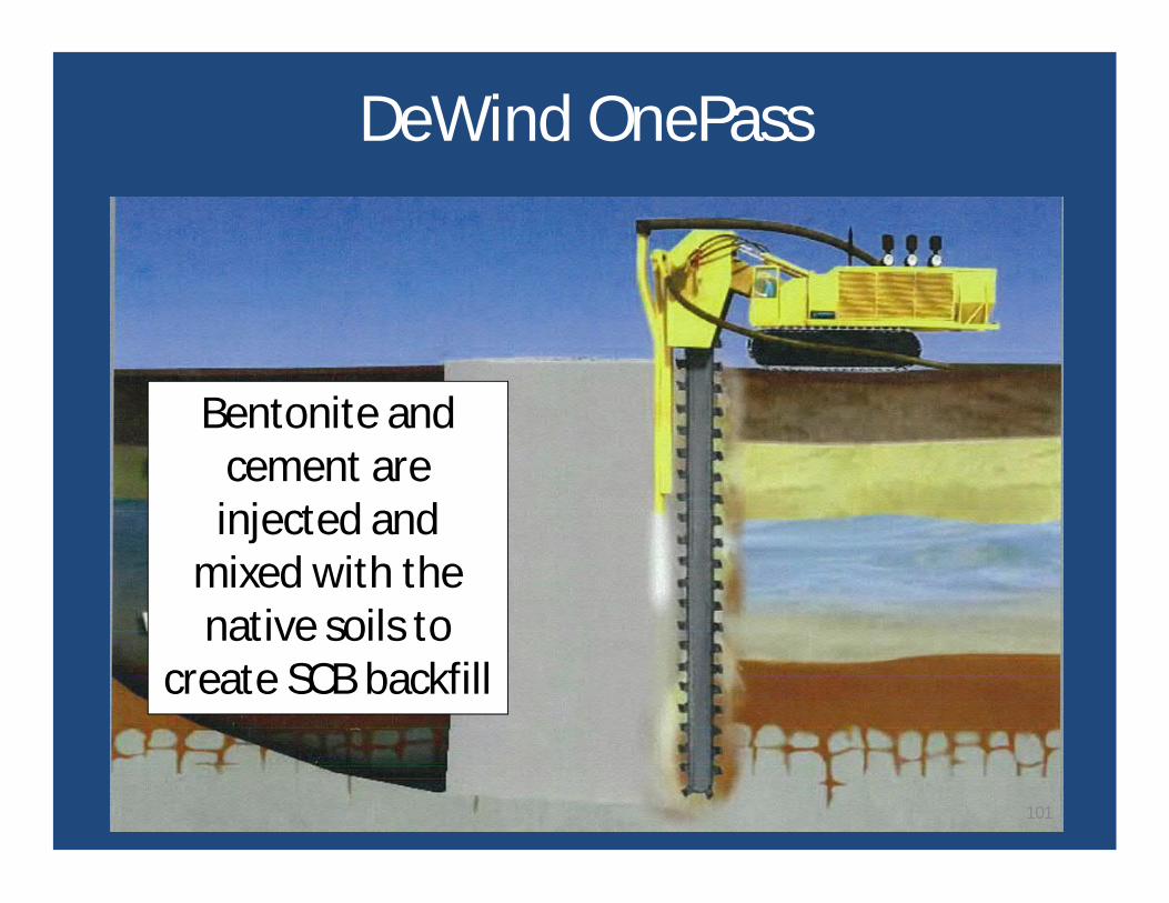
DeWind OnePass
Bentonite andcement areinjected and
mixed with thenative soils to
create SCB backfill
101
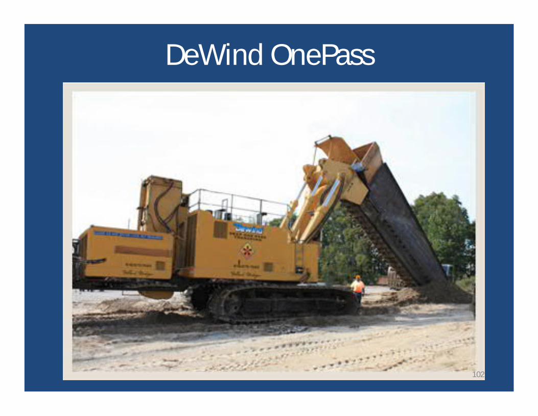
DeWind OnePass
102

DeWind OnePass
103

Element Barrier Walls
• Installed in primary / secondary sequence.• Panels and secant piles are common elements.• Can extend to great depths, but alignment
control, joint integrity, and backfill quality canbe challenging.– Pilot holes and guided equipment have been used
to address alignment.
104
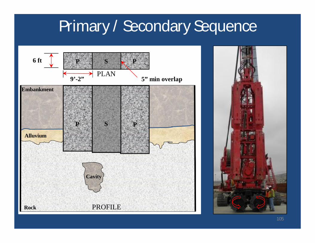
Primary / Secondary Sequence
Embankment
Rock
P
P P
5” min overlap
SP
S
9’-2”
6 ft
Alluvium
PLAN
PROFILE
Cavity
105
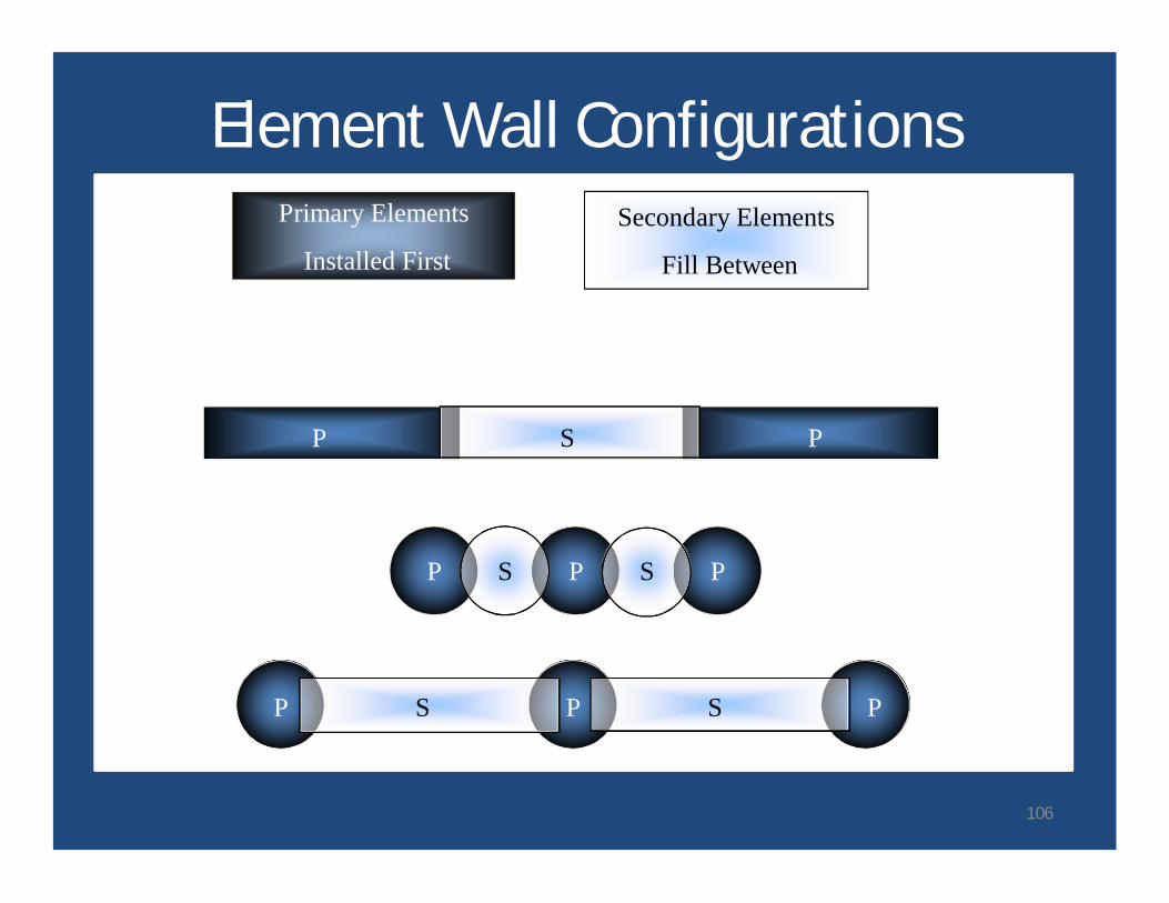
Element Wall ConfigurationsPrimary Elements
Installed FirstSecondary Elements
Fill Between
P P PS S
P PS
P P PS S
106
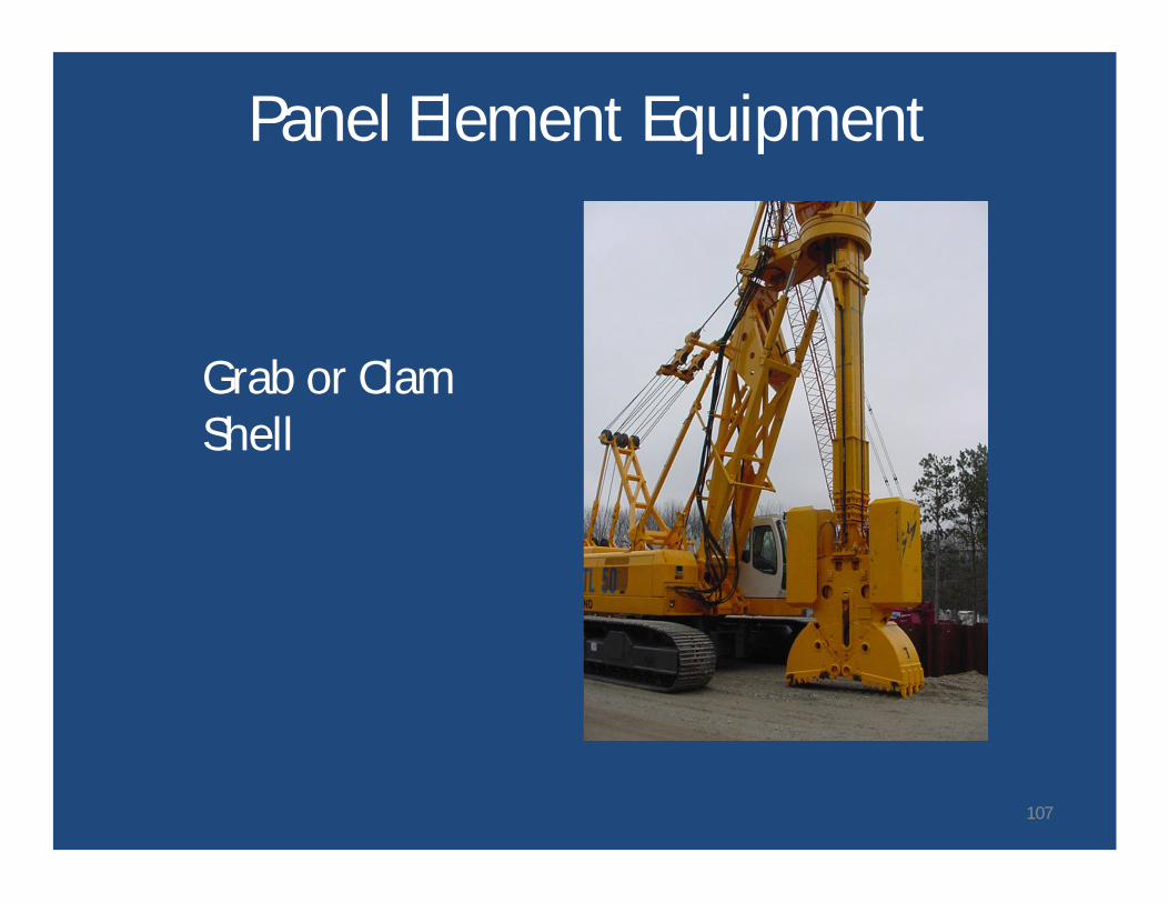
Panel Element Equipment
Grab or ClamShell
107
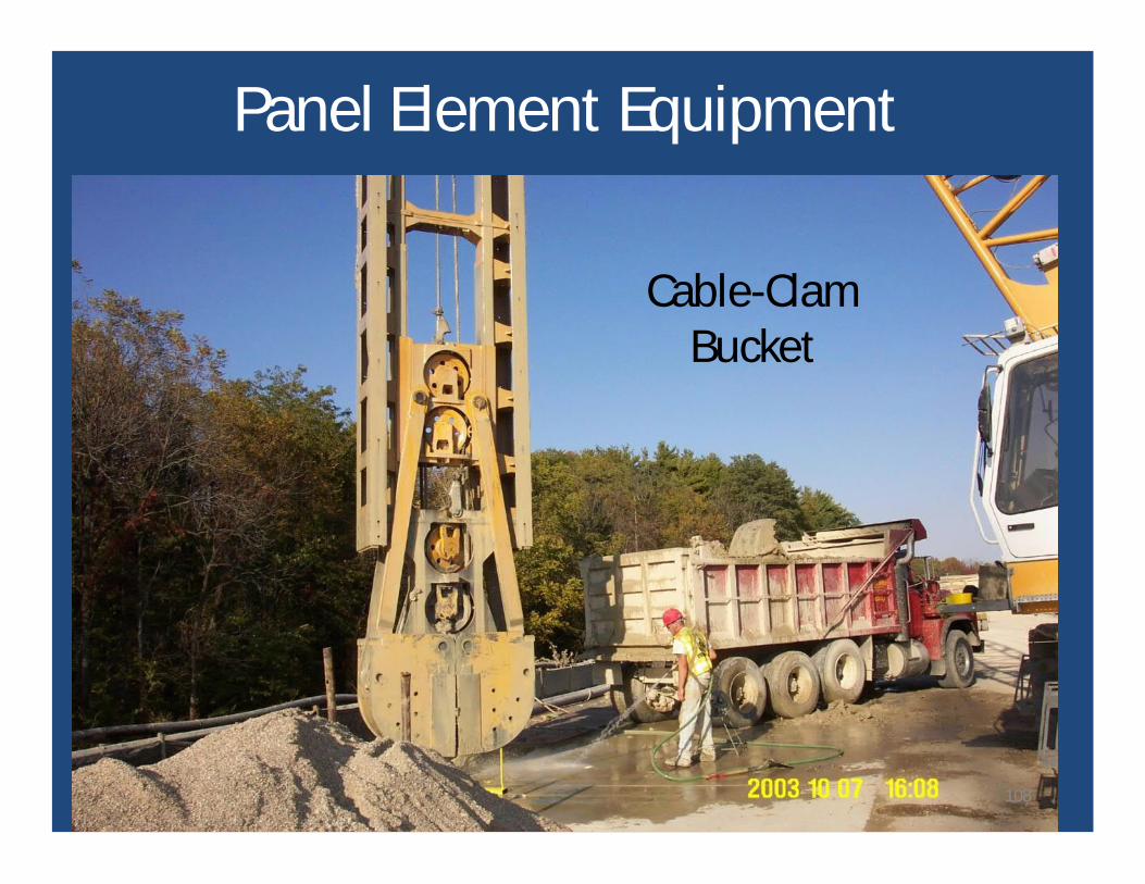
Panel Element Equipment
Cable-ClamBucket
108
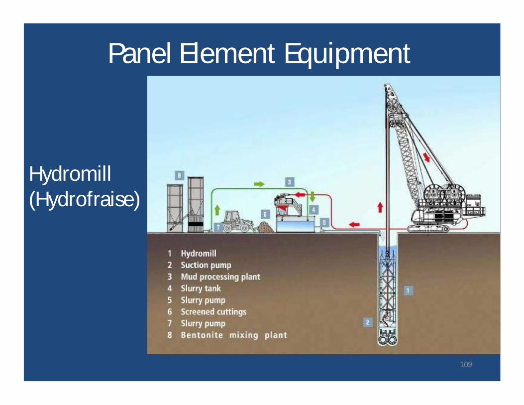
Panel Element Equipment
Hydromill(Hydrofraise)
109
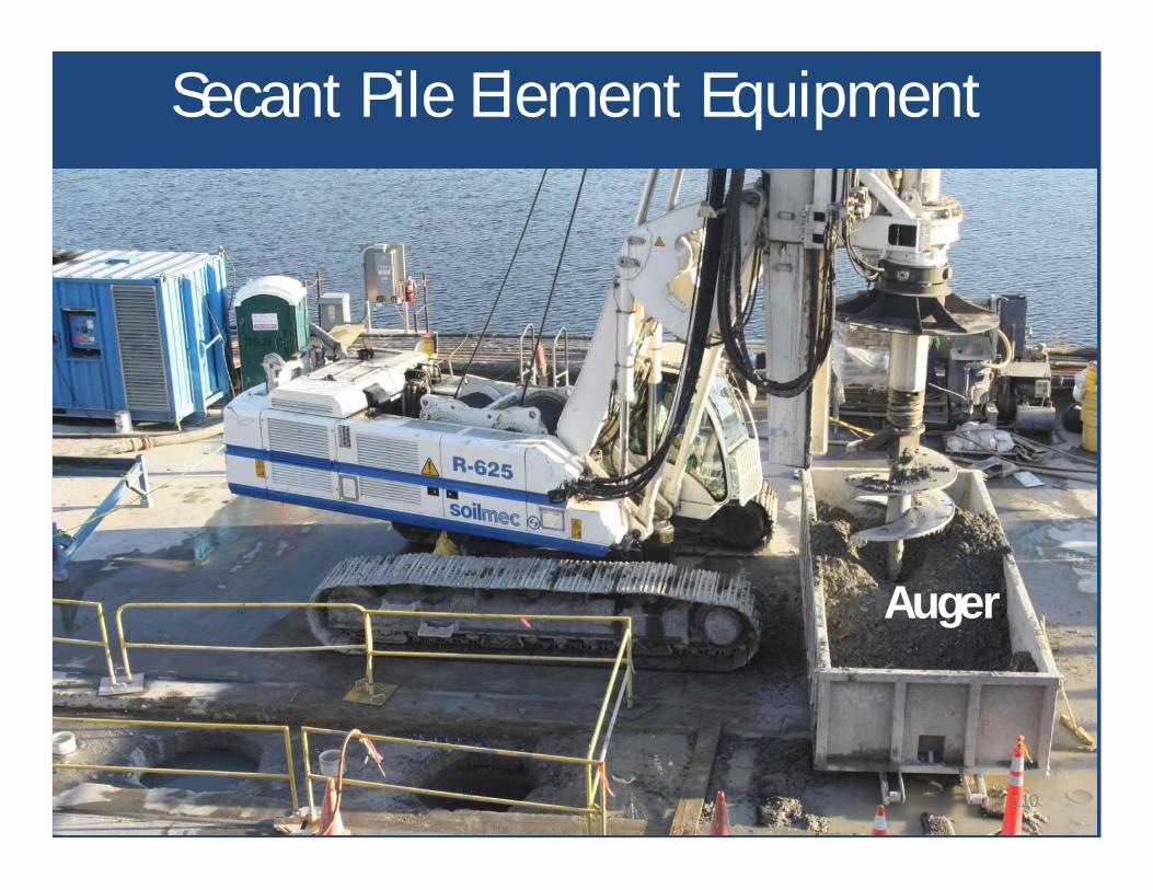
Secant Pile Element Equipment
Auger
110
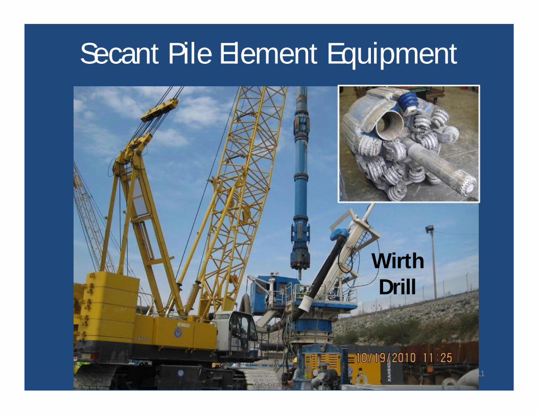
WirthDrill
Secant Pile Element Equipment
111
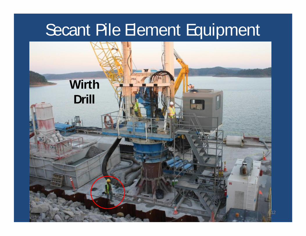
Secant Pile Element Equipment
WirthDrill
112
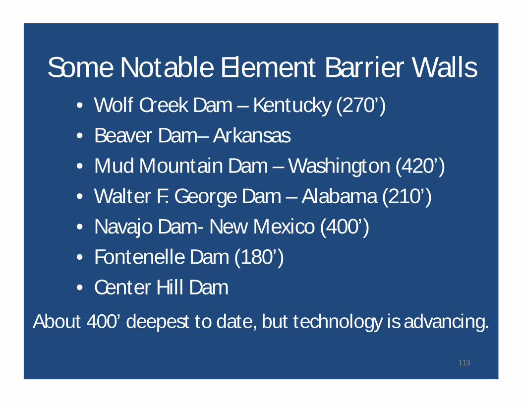
Some Notable Element Barrier Walls• Wolf Creek Dam – Kentucky (270’)• Beaver Dam– Arkansas• Mud Mountain Dam – Washington (420’)• Walter F. George Dam – Alabama (210’)• Navajo Dam- New Mexico (400’)• Fontenelle Dam (180’)• Center Hill Dam
About 400’ deepest to date, but technology is advancing.
113
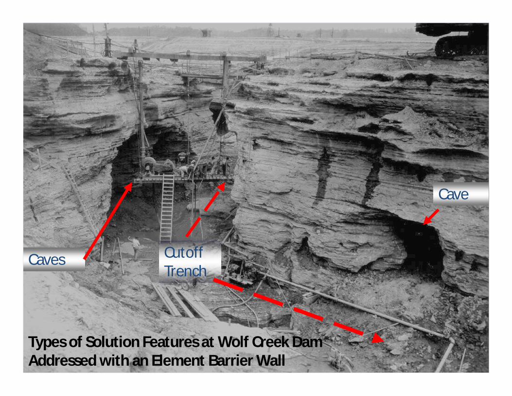
Foundation Treatment
Types of Solution Features at Wolf Creek DamAddressed with an Element Barrier Wall
Caves CutoffTrench
Cave
114
Jet Grouting - Features
• Suitable in a wide range of soils and applications.• Columns with diameters ranging from 60 cm up
to 250 cm (and perhaps more), by using smallsize drilled holes.
• Capability to overpass pre-existing masonry,boulders, rocky layers and obstructions.
• Use of light weight and small-sized drilling rigsable to operate in limited working areas.
115
Jet Grouting - Commentary
• Jet grouting is a soil improvement method.• Jet grouted soil can work in compression and
shear, not in tension.• Jet grouted soil can be reinforced, but it is
not a concrete structure.• Depth limited only by drilling capability, but
alignment and continuity will be a concern atlarge depths.
• Expensive on a per volume basis.116
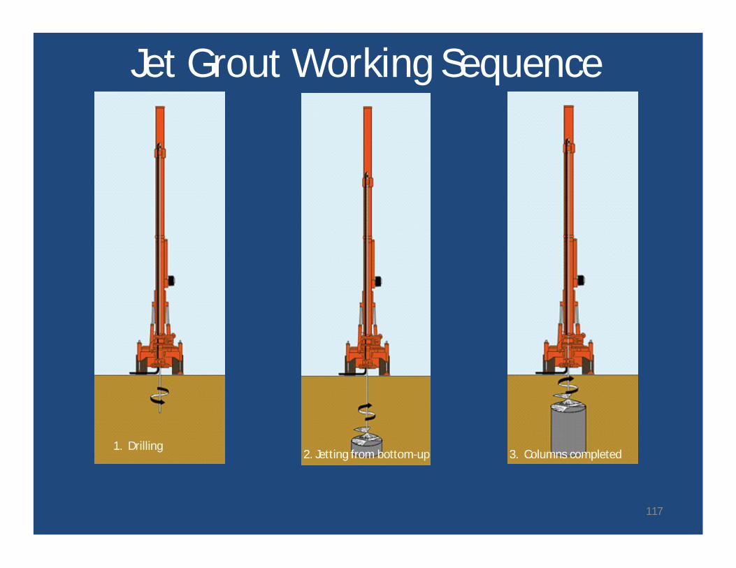
Jet Grout Working Sequence
1. Drilling3. Columns completed2. Jetting from bottom-up
117
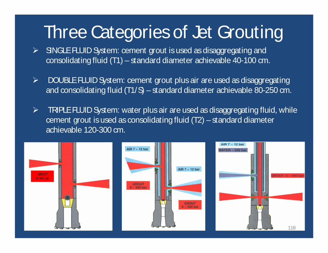
Ø SINGLE FLUID System: cement grout is used as disaggregating andconsolidating fluid (T1) – standard diameter achievable 40-100 cm.
Ø DOUBLE FLUID System: cement grout plus air are used as disaggregatingand consolidating fluid (T1/S) – standard diameter achievable 80-250 cm.
Ø TRIPLE FLUID System: water plus air are used as disaggregating fluid, whilecement grout is used as consolidating fluid (T2) – standard diameterachievable 120-300 cm.
GROUT0-500 bar
Three Categories of Jet Grouting
118
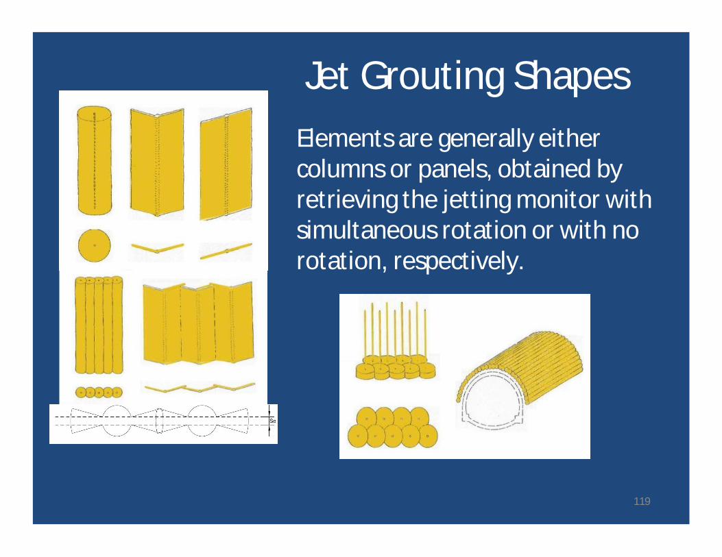
Jet Grouting ShapesElements are generally eithercolumns or panels, obtained byretrieving the jetting monitor withsimultaneous rotation or with norotation, respectively.
119
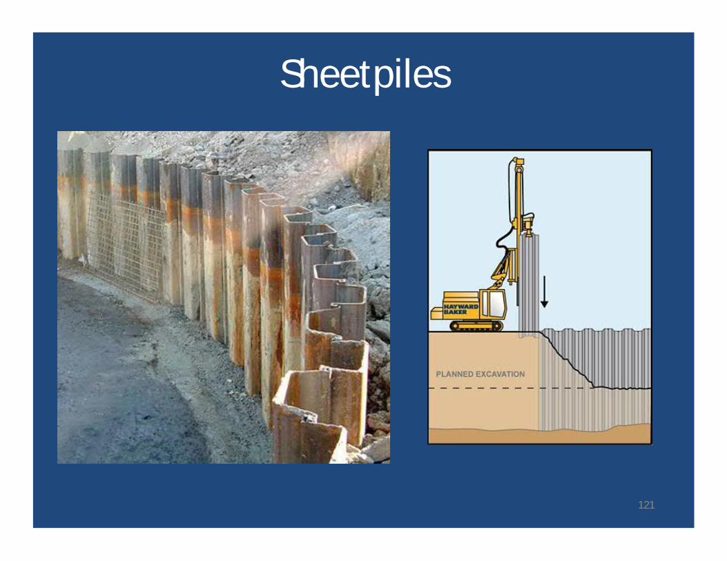
SheetpilesConventional sheetpiles can be used fortemporary or permanent seepage barriers.
• Sheetpiles can be either steel or plastic (vinyl).• Issues include:
− corrosion of steel sheetpile.− buckling of steel or plastic sheetpile.− lack of advancement.− interlock separation.− interlock leakage.
• Realistic depths of 100 feet or less.
120
Sheetpiles
121
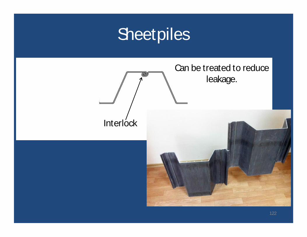
Sheetpiles
Can be treated to reduceleakage.
Interlock
122
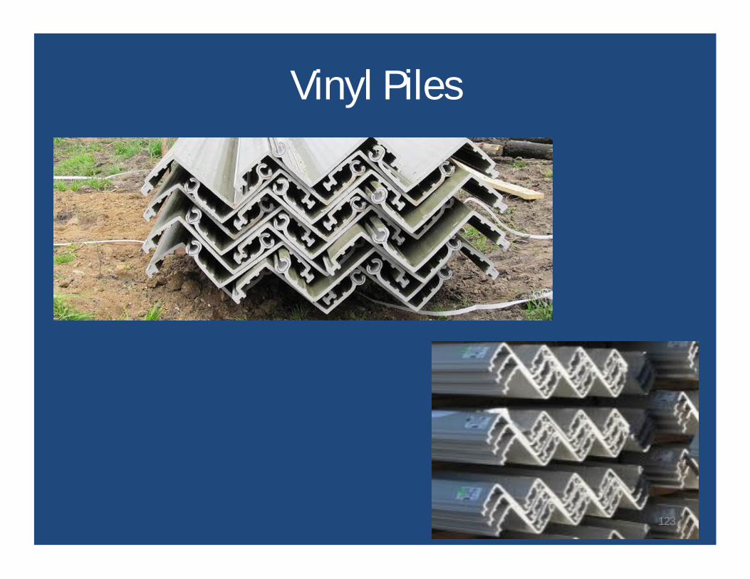
Vinyl Piles
123
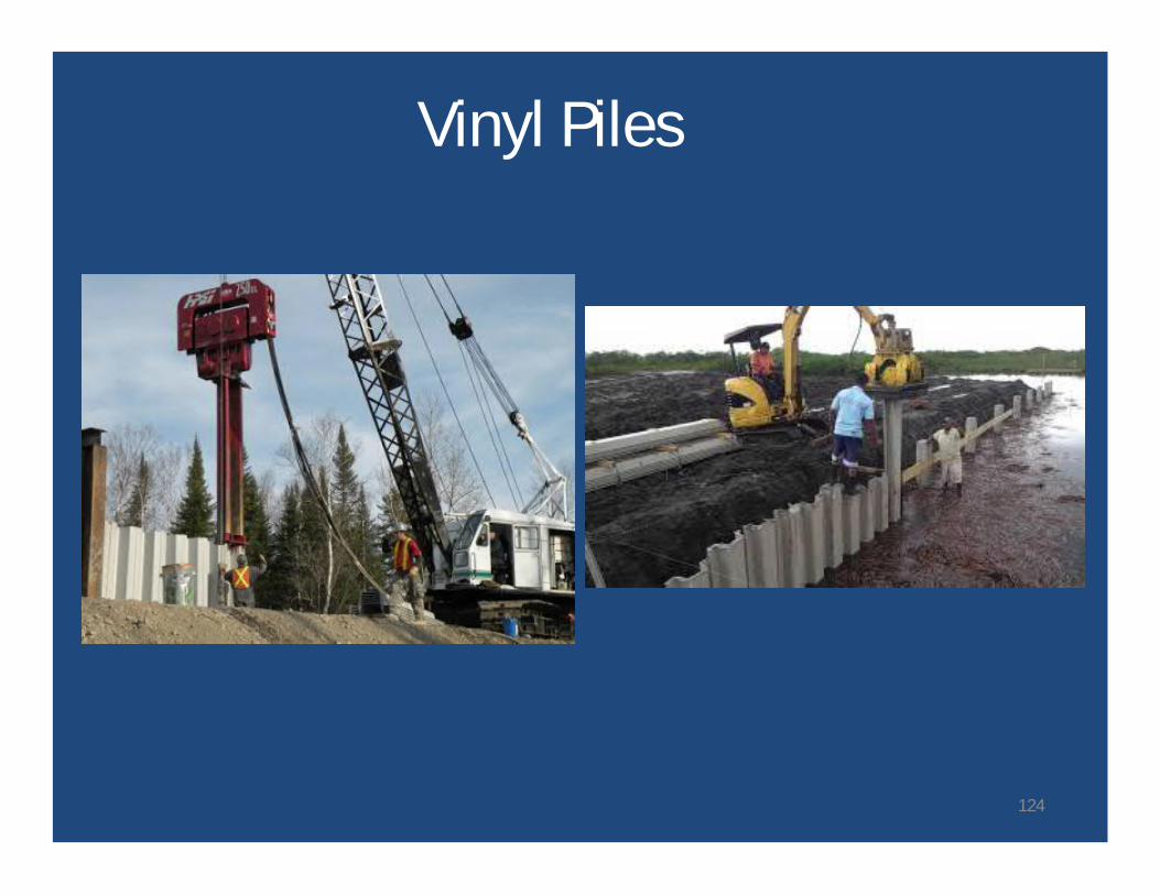
Vinyl Piles
124
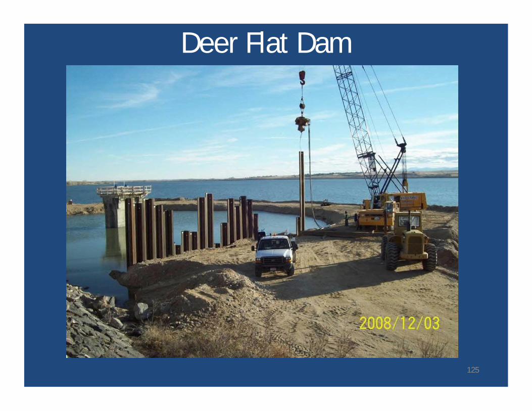
Deer Flat Dam
125
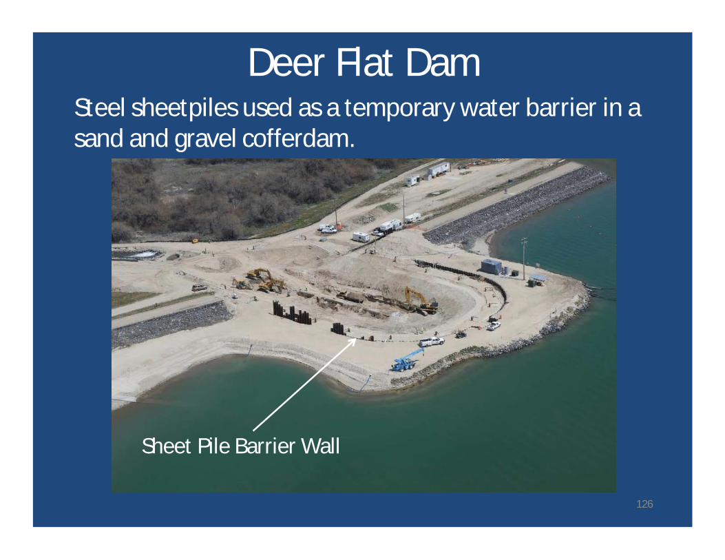
Deer Flat DamSteel sheetpiles used as a temporary water barrier in asand and gravel cofferdam.
Sheet Pile Barrier Wall
126
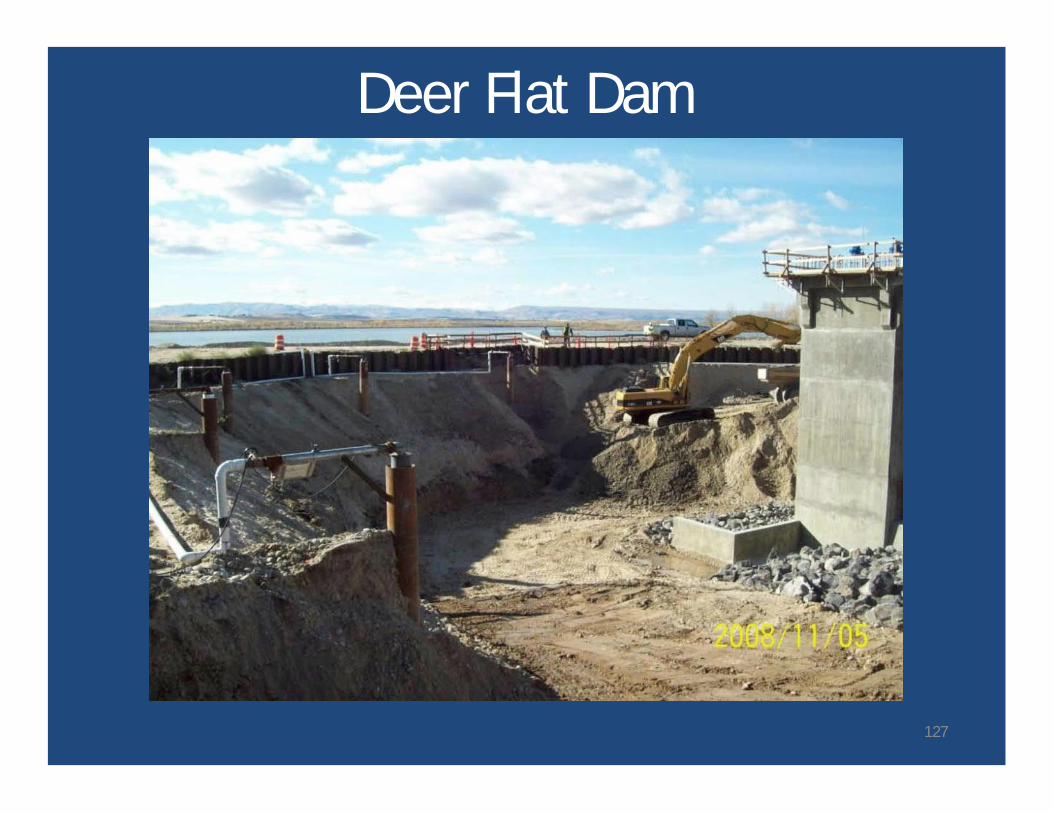
Deer Flat Dam
127
Closing
• Dam engineers have a wide range of toolsavailable for seepage rehabilitation.
• The challenge is to consider, with an openmind, the range of options and select the“best” choice for a particular dam.
• Robustness, redundancy, and resiliency shouldbe duly considered in the selection.
128
Questions?
129