Embed Size (px)
Citation preview

Seeding FLASH between 4 and 40 nm
Kirsten Hacker, TU Dortmund
FLASH1 Seeding Collaboration
University of HamburgJ. Rossbach
J. Roensch-SchulenbergV. Miltchev
J. Boedewadt**C. Lechner*
S. Ackermann*
TU Dortmund/U.StockholmS. Khan
K. Hacker**R. Molo*P. Salen
DESYI. Hartl
N. Ekanayake**H. SchlarbB. Faatz
T. Tanikawa
** primary responsibility*student
FEL diagnosticsM. DrescherT. Laarmann
A. AzimaT. Maltezopoulos**
BMBF
BMBFARD
BMBF

Outline
• HGHG seeding limits at FLASH• EEHG seeding limits at FLASH• Cascaded seeding limits at FLASH• Seeding at other labs• A proposed layout for FLASH2• Conclusion
All simulations are 1-D3-D effects are estimated

Seeded FEL• More intense and monochromatic radiation• Shorter undulator required
λ

Seeded FEL
• Convenient for pump-probe experiments
PumpProbe

Types of external seeding
• HHG direct seeding
• HGHG seeding
• EEHG seeding
• cascading
Harmonic
gas jet
RadiateHarmonic
ModulateEnergy
Bunch
Amplify
RadiateModulateEnergy
Bunch
ModulateEnergy
Fold
Radiateseeded light
AmplifyHarmonic
fresh bunchchicane
Seeding

HGHG seedingHigh Gain Harmonic Generation
RadiateModulateFold
ModulateBunch
RadiateHarmonic
ModulateEnergy
BunchRadiate
ModulateEnergy BunchDelay
RadiateHarmonic
ModulateEnergy
Bunch
Slice Energy Spread
270 nm
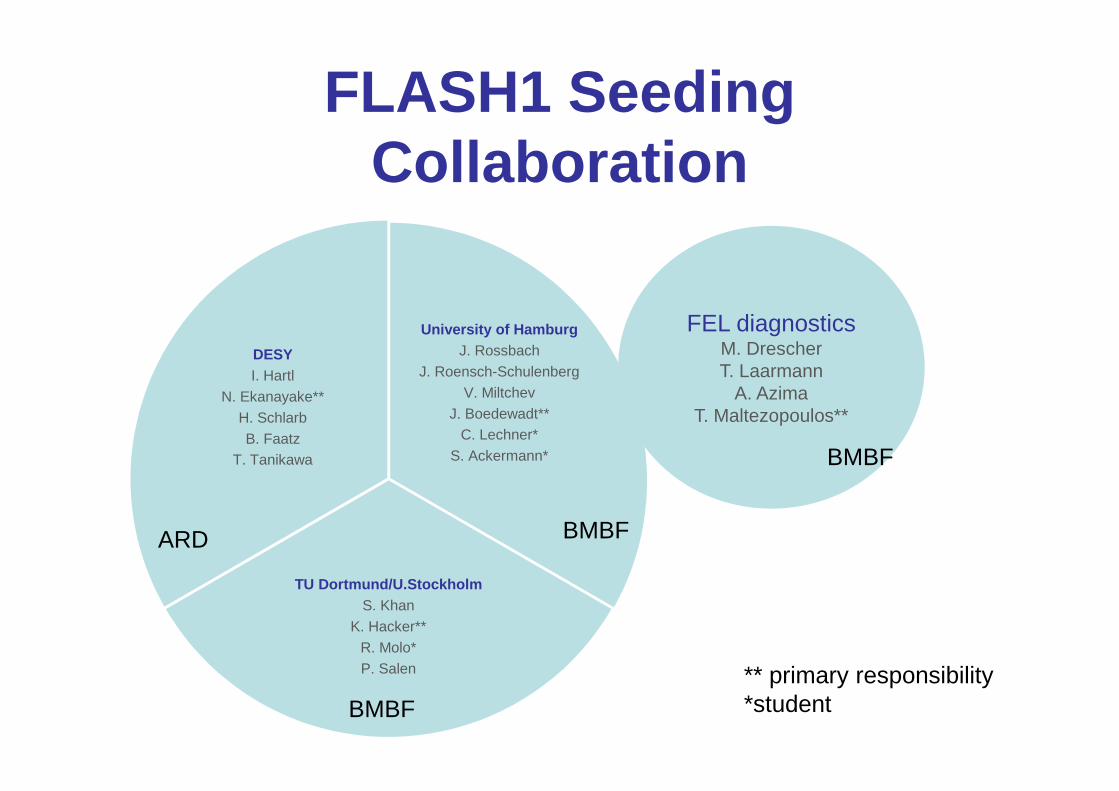
HGHG limit at FLASH2
limit: uncorrelated energy spread of electron beam
Modulator
Laser
λ=270 nmBunch
Radiator
2 meters, 30 periods 4* U32R56=50 um
700 MeV∆E/E<4*10-3

HGHG limit at FLASH2
limit: too high peak current
Modulator
Laser
λ=270 nmBunch
Radiator
2 meters, 30 periods
700 MeV∆E/E<4*10-3
4* U32
38.5 nm 15 nm

CSR and LSC4 MeV microbunch after 4 meters
100 µm (rms) beam radius1kA initial peak currentR56 of chicane = 45 µm700 MeV beam energy
Only small degradation in bunchingBut – energy spread is too big
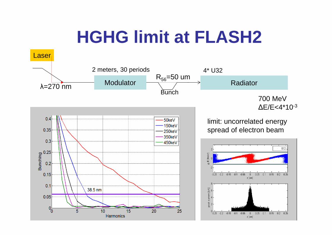
CSR and LSC2MeV microbunch after 4 meters
100 µm (rms) beam radius1kA initial peak currentR56 of chicane = 45 µm700 MeV beam energy

CSR and LSC2MeV microbunch after 4 meters
CSR only
LSC only
100 µm (rms) beam radius1kA initial peak currentR56 of chicane = 45 µm700 MeV beam energy
−=
γγπbb
bLSC
krK
kr
kr
iZkZ 1)(
20

FLASH2 beamlineProposed, 30 nm HGHG
o
Alternative, 4-40 nm EEHG/HGHG/HHG/cascade
o
o
Caveats:1). The saturation point has to be at a fixed position in the undulator2). For long wavelengths, the saturation point has to be at the end3). Transport the bunched or modulated beam over 30 m 4). Quad focusing might reduce the bunching due to T126 effects. 5). Everything not yet considered.

Dispersion in 30 meter Drift
• R56 ~ Ldrift/γ2 = 15 µm ~ 700 MeV• R56 ~ Ldrift*θ2 < 3 nm ~ worst case 100 µm• T126 ~ lbend (sextupole moment)
• R11 ~ cosθ=1• R12 ~ θ/lbend sin(θ/lbend)=0• R16 ~ 2*R56*θ=0
Dispersion required to bunch seeded microbunch is:20 µm for too-large 4 MeV modulation50 µm for smaller 2 MeV modulation>50 µm for smaller modulations
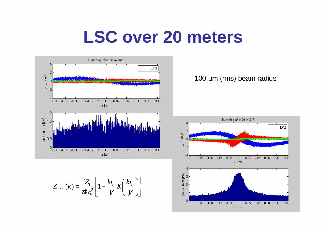
LSC over 20 meters
100 µm (rms) beam radius
−=
γγπbb
bLSC
krK
kr
kr
iZkZ 1)(
20

Increase beam diameter to remove LSC problem
100 µm 200 µm
Bonus: no CSR because beam was compressed in drift

EEHG seedingEcho Enabled Harmonic Generation
Modulator Modulator
Laser
λ=270 nm
Fold Bunch
R56<1 mm R56<100 µm

EEHG limit at FLASH2
Modulator Modulator
Laser
λ=270 nm
Fold Bunch
7 nm
R56<1 mm R56<100 µm
∆E/E<4*10-3

EEHG doesn’t tolerate LSC
=> Need large beam size and higher energy in drift, and/or split radiator
Rad2Drift w/ LSCMod 2Mod 1
Rad2drift without LSC
Mod 2Mod 1
Rad1
1kA peak current30 meters of drift100 um radius

EEHG tolerates CSR1kA peak current30 meters of drift300 um radius (minimizes LSC)70 um R56

EEHG-HHG limit at FLASH2
Undulator Undulator
P~250 kW
λ=260 nm
∆E/E<4*10-3
P~1 GW
λ=260 nm, 30 fs
HHG
λ=60 nm
3.5 nm
Laser
Flatter current distributionis better for LSC and CSR

Cascaded seeding at FLASH2
Radiator 1 Radiator 2Modulators
1GWSeeded14 nm
Seeded 4.7 nm
“fresh bunch”chicane
∆E ∆E 3rd harmonic
0 2 4 6 8 10 120
1
2
3
4
5
6
x 10-15
harmonic number
peak
pow
er [a
.u.]
4.7 nm
2.8 nm
EEHG cascade tolerates 450 keV slice energy spread12-24 nm -> 3rd harmonic -> seeded 4-8 nm
HGHG cascade tolerates 150 keV slice energy spread24-36 nm ->3rd harmonic -> 8-12 nm
14 nm
Seeding at other labs
• SINAP– EEHG at 300 nm, but moving very fast
• SLAC (NLCTA)– EEHG at 170 nm (14th harmonic)
• ELLETRA (FERMI)– HGHG down to 19 nm– HGHG cascade down to 4 nm
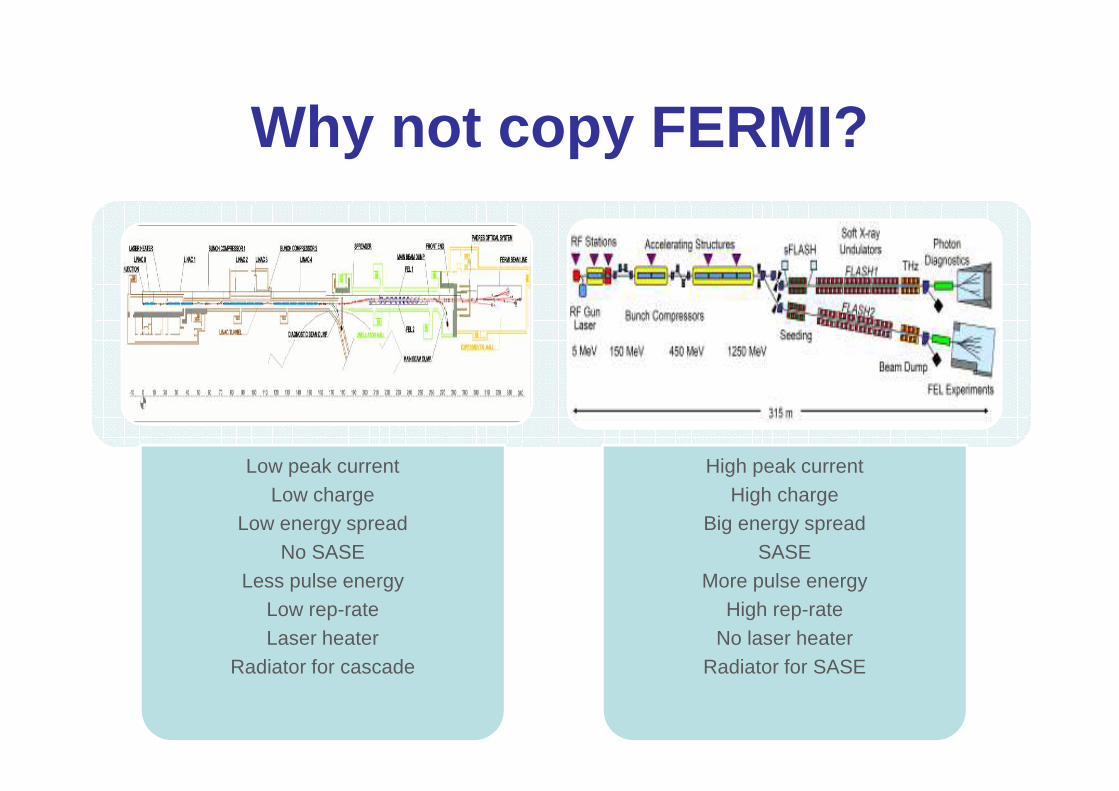
Why not copy FERMI?
Low peak currentLow charge
Low energy spreadNo SASE
Less pulse energyLow rep-rateLaser heater
Radiator for cascade
High peak currentHigh charge
Big energy spreadSASE
More pulse energyHigh rep-rate
No laser heaterRadiator for SASE
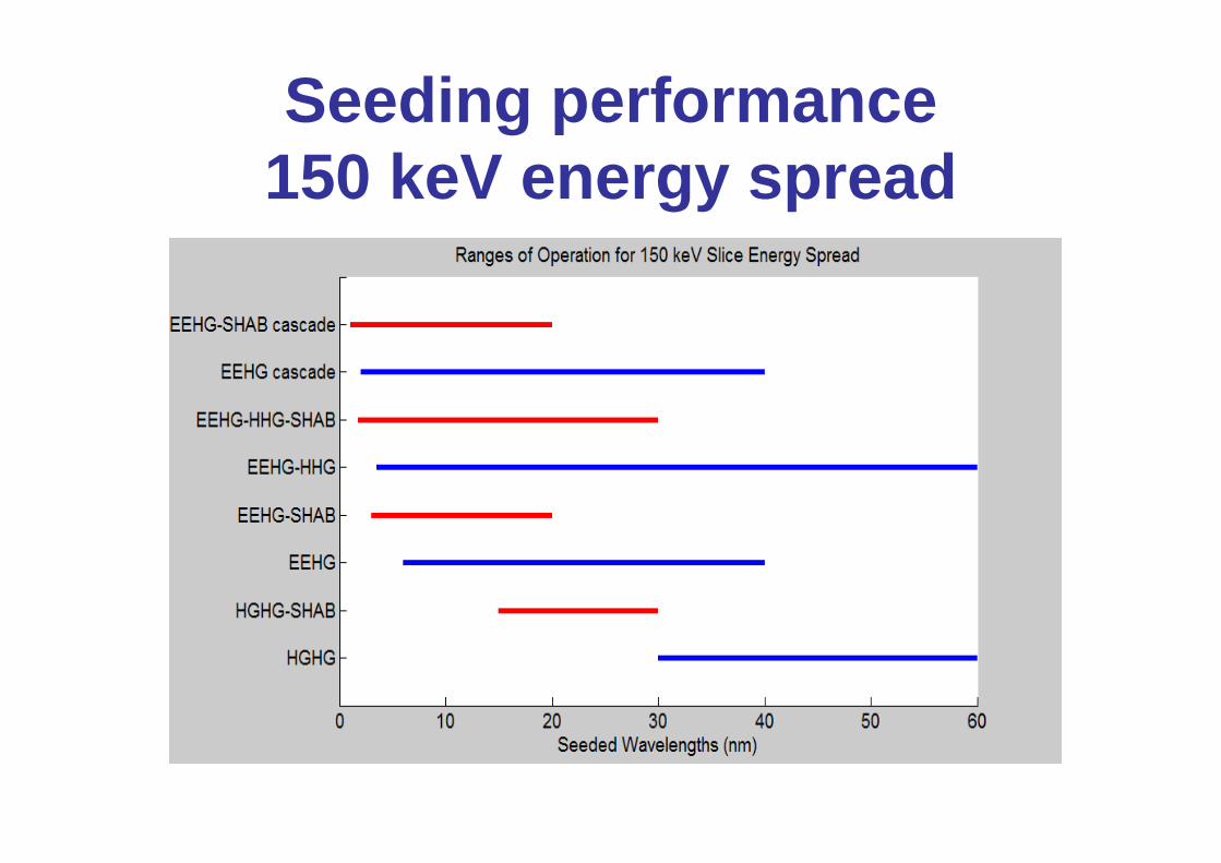
Seeding performance 150 keV energy spread

Seeding performance 150 keV energy spread

Conclusions• EEHG has the highest tolerance of a bad slice
energy spread
• The HGHG-only FLASH2 design is limited in performance to 150 keV energy spreads and 30 nm minimum wavelengths
• The more flexible design for FLASH2 offers more ways to seed from 4-40 nm and with a larger tolerance of the slice energy spread

X-Band Transverse Deflecting Structure for FLASH2
(addendum)
• giving users information about the longitudinal profile of the FEL pulse for each bunch train
• R&D for LAOLA ultra-short bunch diagnostics
• commissioning the FLASH II extraction line
• operating any seeding experiments• energy modulation diagnostic
Images from C. Behrens
100 fs seeduncompressed ebeam

Thank you for your time