Embed Size (px)
Citation preview
Sedimentary Rocksin the Field
THIRD EDITION
Maurice E. TuckerDepartment of Geological Sciences
University of Durham, UK


Sedimentary Rocksin the Field

The Geological Field Guide SeriesBasic Geological Mapping, Third edition John BarnesThe Field Description of Metamorphic Rocks Norman FryThe Mapping of Geological Structures Ken McClayField Geophysics, Third edition John MilsomThe Field Description of Igneous Rocks Richard Thorpe & Geoff BrownSedimentary Rocks in the Field, Third edition Maurice Tucker

Sedimentary Rocksin the Field
THIRD EDITION
Maurice E. TuckerDepartment of Geological Sciences
University of Durham, UK

Copyright 2003 by John Wiley & Sons Ltd,The Atrium, Southern Gate, Chichester,West Sussex PO19 8SQ, England
Telephone (+44) 1243 779777
Email (for orders and customer service enquiries): [email protected]
Visit our Home Page on www.wileyeurope.com or www.wiley.com
First edition first published under the title The Field Description of Sedimentary Rocks in 1982 by Open
University Press, and Halsted Press (a division of John Wiley Inc.) in the USA, Canada and Latin America.
Copyright Maurice E. Tucker 1982.
Second edition first published in 1996 by John Wiley & Sons Ltd. Copyright 1996 John Wiley & Sons
Ltd.
All Rights Reserved. No part of this publication may be reproduced, stored in a retrieval system or
transmitted in any form or by any means, electronic, mechanical, photocopying, recording, scanning or
otherwise, except under the terms of the Copyright, Designs and Patents Act 1988 or under the terms of a
licence issued by the Copyright Licensing Agency Ltd, 90 Tottenham Court Road, London W1T 4LP, UK,
without the permission in writing of the Publisher. Requests to the Publisher should be addressed to the
Permissions Department, John Wiley & Sons Ltd, The Atrium, Southern Gate, Chichester, West Sussex
PO19 8SQ, England, or emailed to [email protected], or faxed to (+44) 1243 770620.
This publication is designed to provide accurate and authoritative information in regard to the subject
matter covered. It is sold on the understanding that the Publisher is not engaged in rendering professional
services. If professional advice or other expert assistance is required, the services of a competent
professional should be sought.
Other Wiley Editorial Offices
John Wiley & Sons Inc., 111 River Street, Hoboken, NJ 07030, USA
Jossey-Bass, 989 Market Street, San Francisco, CA 94103-1741, USA
Wiley-VCH Verlag GmbH, Boschstr. 12, D-69469 Weinheim, Germany
John Wiley & Sons Australia Ltd, 33 Park Road, Milton, Queensland 4064, Australia
John Wiley & Sons (Asia) Pte Ltd, 2 Clementi Loop #02-01, Jin Xing Distripark, Singapore 129809
John Wiley & Sons Canada Ltd, 22 Worcester Road, Etobicoke, Ontario, Canada M9W 1L1
Wiley also publishes its books in a variety of electronic formats. Some content that appears in print may
not be available in electronic books.
British Library Cataloguing in Publication Data
A catalogue record for this book is available from the British Library
ISBN 0-470-85123-6
Typeset in 8.5/10.5pt Times by Laserwords Private Limited, Chennai, India
Printed and bound in Great Britain by Antony Rowe Ltd, Chippenham, Wiltshire
This book is printed on acid-free paper responsibly manufactured from sustainable forestry
in which at least two trees are planted for each one used for paper production.

Contents
Preface viiAcknowledgements ix
1 Introduction 11.1 Tools of the Trade 11.2 Other Tools for the Field 21.3 Use of GPS in Sedimentary Studies 31.4 Safety in the Field and General Guidance for Fieldwork 4
2 Field Techniques 72.1 What to Look for 72.2 The Approach 82.3 Field Notes 92.4 Graphic Logs 102.5 The Logging of Cores 152.6 Lithofacies Codes 162.7 Collecting Specimens 172.8 Presentation of Results 182.9 The Way-Up of Sedimentary Strata 19
2.10 Stratigraphic Practice 20
3 Sedimentary Rock Types 293.1 Principal Lithological Groups 293.2 Sandstones 323.3 Conglomerates and Breccias 363.4 Mudrocks 393.5 Limestones 403.6 Evaporites 513.7 Ironstones 533.8 Cherts 553.9 Sedimentary Phosphate Deposits (Phosphorites) 57
3.10 Organic-Rich Deposits 583.11 Volcaniclastic Deposits 59
4 Sedimentary Rock Texture 674.1 Introduction 674.2 Sediment Grain Size and Sorting 674.3 Grain Morphology 694.4 Sediment Fabric 724.5 Textural Maturity 75
v

CONTENTS
4.6 Texture of Conglomerates and Breccias 764.7 Induration and Degree of Weathering 774.8 Colour of Sedimentary Rocks 79
5 Sedimentary Structures and Geometry of SedimentaryDeposits 835.1 Introduction 835.2 Erosional Structures 835.3 Depositional Structures 885.4 Depositional Structures of Limestones (Including
Dolomites) 1195.5 Post-Depositional Sedimentary Structures 1275.6 Biogenic Sedimentary Structures 1435.7 Geometry of Sedimentary Deposits and Lateral Facies
Changes 158
6 Fossils in the Field 1636.1 Introduction 1636.2 Fossil Distribution and Preservation 1666.3 Fossil Associations and Diversity 1706.4 Skeletal Diagenesis 174
7 Palaeocurrent Analysis 1797.1 Introduction 1797.2 Palaeocurrent Measurements 1797.3 Structures for Palaeocurrent Measurement 1857.4 Presentation of Results and Calculation of Vector Means 1877.5 Interpretation of the Palaeocurrent Pattern 188
8 What Next? Facies Analysis, Cycles and Sequences 1918.1 Introduction 1918.2 Facies Analysis 1918.3 Facies Models and Depositional Environments 1938.4 Cycle Stratigraphy and Sequence Stratigraphy 194
References and Further Reading 225
Index 229
vi

PREFACE
The study of sedimentary rocks is often an exciting, challenging, rewardingand enjoyable occupation. However, to get the most out of these rocks, itis necessary to undertake precise and accurate fieldwork. The secret of suc-cessful fieldwork is a keen eye for detail and an enquiring mind; knowingwhat to expect and what to look for are important, although you do need tokeep an open mind. Be observant, see everything in the outcrop, then thinkabout the features seen and look again. This book is intended to show howsedimentary rocks are tackled in the field and has been written for those witha geological background of at least first-year university or equivalent.
At the outset, this book describes how the features of sedimentary rockscan be recorded in the field, particularly through the construction of graphiclogs. The latter technique is widely used since it provides a means of record-ing all details in a handy form; further, from the data, trends through asuccession and differences between horizons readily become apparent. Insucceeding chapters, the various sedimentary rock types, textures and struc-tures are discussed as they can be described and measured in the field. Ashort chapter deals with fossils, since these are an important component ofsedimentary rocks and much useful information can be derived from them forpalaeoenvironmental analysis; they are also important in stratigraphic corre-lation and palaeontological studies. Having collected the field information,there is the problem of knowing what to do with it. A concluding sectiondeals briefly with facies identification and points the way towards faciesinterpretations, and the identification of sequences and cycles.
Maurice E. Tucker
vii


ACKNOWLEDGEMENTS
I should like to thank the many friends and colleagues who have willinglyread drafts of this handbook and kindly provided photographs. I am indebtedto Vivienne for support, encouragement and helping in the ways that only awife can.
ix


1INTRODUCTION
This book aims to provide a guide to the description of sedimentary rocks inthe field. It explains how to recognise the common lithologies, textures andsedimentary structures, and how to record and measure these features. Thereis a chapter explaining how fossils can be studied in the field, since theyare common in many sedimentary rocks and are very useful for palaeoen-vironmental analysis. A concluding chapter gives a brief introduction to theinterpretation of sedimentary rock successions: facies, facies associations,cyclic sediments and sequences.
1.1 Tools of the TradeApart from a notebook (popular size around 20× 10 cm), pens, pencils,appropriate clothing, footwear and a rucksack, the basic equipment of a fieldgeologist comprises a hammer, chisel, hand-lens, compass-clinometer, tapemeasure, acid bottle, sample bags and marker pen. A GPS receiver is mostuseful, and not only in remote areas (see Section 1.3). A hard hat for pro-tection when working below cliffs and in quarries, and safety goggles forthe protection of the eyes while hammering, should also be taken into thefield and used; see Section 1.4 for further safety considerations. A camera,plus spare film or memory, is invaluable. Topographic and geological mapsshould also be carried, as well as any pertinent literature. If a lot of graphiclogging is anticipated (see Section 2.4) then pre-prepared sheets can be takeninto the field. Non-geological items which are useful and can be carried in arucksack include a whistle, first-aid equipment, matches, emergency rations,knife, waterproof clothing and a ‘space blanket’.
For most sedimentary rocks, a geological hammer of around 0.5–1 kg(1–2 lb) is sufficiently heavy. However, do be sympathetic to the outcropand remember that many future generations of geologists will want to lookat the exposure. In many cases it will not be necessary to hammer, since itwill be possible to collect loose fresh pieces from the ground. A range ofchisels can be useful if a lot of collecting is anticipated.
A hand-lens is an essential piece of equipment;×10 magnification isrecommended since then grains and features down to 100 microns acrosscan be observed. Holding the lens close to your eye, the field of view being
Sedimentary Rocks in the Field. Maurice E. Tucker 2003 John Wiley & Sons, Ltd ISBN: 0-470-85123-6
1
INTRODUCTION
examined with a×10 lens is about 10 mm in diameter. To become familiarwith the size of grains as seen through a hand-lens, examine the grains againsta ruler graduated in millimetres. For limestones, it can be easier to see thegrains after licking the freshly broken surface.
A compass-clinometer is important for taking routine dip and strike andother structural measurements, but also for measuring palaeocurrent direc-tions. Do not forget to correct the compass for the angle between magneticnorth and true north. This angle of declination is normally given on topo-graphic maps of the region. You should also be aware that power lines,pylons, metal objects (such as your hammer) and some rocks (although gen-erally mafic–ultramafic igneous bodies) can affect the compass reading andproduce spurious results. A tape or steel rule, preferably several metres inlength, is necessary for measuring the thickness of beds and dimensions ofsedimentary structures. A metre-long staff with graduations can be usefulfor graphic logging. A compass usually has a millimetre–centimetre scalewhich can be useful for measuring the size of small objects such as pebblesand fossils.
For the identification of calcareous sediments a plastic bottle of hydrochlo-ric acid (around 10%) is useful, and if some Alizarin red S is added, then dolo-mites can be distinguished from limestones (limestones stain pink, dolomitesdo not stain). Polythene or cloth bags for samples and a marker pen (prefer-ably with waterproof, quick-drying ink) for writing numbers on the specimensare also necessary. Friable specimens and fossils should be carefully wrappedto prevent breakage.
For modern sedimentsandunconsolidated rocksyou will need a troweland/or spade. A length (0.5–1.5 metres) of clear plastic pipe, 5–10 cm indiameter, is very useful for pushing into modern sediments to obtain a crudecore. Epoxy-resin cloth peels can be made in the field of vertical sectionsthrough soft sandy sediments. The techniques for taking such peels are givenin Bouma (1969). In essence, cut and trim a flat vertical surface through thesediments; spray the resin on to the cut surface; place a sheet of muslin orcotton against the sediments and then spray the cloth. Leave for the resinto set (∼10 minutes) and then carefully remove the cloth. A thin layer ofsediment should be glued to the cloth and will show the various structures.Lightly brush or shake off excess, unglued sediment. Modern beach, dune,river, tidal flat and desert sediments are ideal for treatment in this way.Fibreglass foam (although a hazardous substance) can also be sprayed on toloose sediment to take a sample.
1.2 Other Tools for the FieldMore sophisticated instruments are taken into the field on occasion to measurea particular attribute of sedimentary rocks. Normally these are used as part
2

INTRODUCTION
of a more detailed and focused research effort, rather than during a routinesedimentological study. Such tools include the mini-permeameter, magneticsusceptibility recorder (kappameter), gamma-ray spectrometer and ground-penetrating radar equipment.
The mini-permeameter is a tool for estimating the permeability of a rockand portable ones are available for use in the field.
The magnetic susceptibility (‘mag-sus’) of sedimentary rocks can be mea-sured relatively easily in the field, although in many it is very weak. Mudrocksand others with high organic matter contents and iron minerals tend to givehigher readings. With measurements taken every few centimetres or so, amag-sus stratigraphy can be produced; from this, cycles and rhythms can berecognised, especially in basinal facies.
Gamma-ray spectrometry is a technique for measuring the natural gammaradiation emitted from rocks; it can be used to determine the amount ofclay in a succession and so is useful for distinguishing different types ofmudrock, or the variation in clay content of muddy sandstones and lime-stones. Measurement of the gamma-ray spectrum in the field with a portablespectrometer has been used to correlate surface outcrops with each other andwith the subsurface.
Ground-penetrating radar is a useful technique for looking at the structureand variation of shallow subsurface sediments, as in modern floodplains andcoastal plains. Sedimentary units, such as point-bar sands and oxbow lakefills, can be recognised beneath the surface.
1.3 Use of GPS in Sedimentary StudiesThe GPS (global positioning system) is becoming a standard instrument totake into the field for determining location, but it can also be used for mea-suring sedimentary sections. GPS provides a very precise location of whereyou are and this reading of latitude and longitude (or grid reference) canbe entered in your field notebook and on logging sheets. The receiver alsoenables you to travel from one place to another or to find a specified location,or to back-track from whence you came. The accuracy of the reading from thereceiver depends on several factors (make and model, time at location, design,corrections, etc.) and the method of positioning. With autonomous GPS theprecision is 5–30 metres; using differential GPS (DGPS) and applying cor-rections, accuracy can be less than 3 metres. However, a reference stationdoes have to be set up for DGPS.
GPS receivers now have a good memory so that all readings from theday, indeed the week, can be recalled, enabling you to retrace your steps andvisit the precise localities again with no difficulty. This is immensely usefulin landscapes where there are no distinctive features. Data from the receiver
3

INTRODUCTION
can of course be downloaded directly to a PC so that a permanent record iskept of where you went.
Apart from the advantage of knowing where you are, GPS does havethe potential to enable you to measure medium to large structures with abetter degree of accuracy than with using just a map and tape measure.With channel-fills, reef bodies, conglomeratic lenses, etc., several hundredmetres across or more, taking several GPS measurements will enable a betterestimate of dimensions to be obtained.
1.4 Safety in the Field and General Guidance for FieldworkWorking in the field should be a safe, enjoyable and very rewarding experi-ence, as long as a few basic and sensible precautions are taken. Geologicalfieldwork is an activity involving some inherent risks and hazards, such asin coastal exposures, quarries, mines, river sections and mountains. Severeweather conditions may also be encountered in any season, especially onmountains or at the coast. Fieldwork does involve an important element ofself-reliance and the ability to cope alone or in a small group. You are respon-sible for your own safety in the field, but nevertheless there are some simpleprecautions you can take to avoid problems and minimise risks.
• Do wear adequate clothing and footwear for the type of weather andterrain likely to be encountered. Try to know the weather forecast for thearea before you go out for the day. Keep a constant lookout for changes.Do not hesitate to turn back if the weather deteriorates.
• Walking boots with good soles are normally essential. Sports shoes areunsuitable for mountains, quarries and rough country.
• Plan work carefully, bearing in mind your experience and training, thenature of the terrain and the weather. Be careful not to overestimate whatcan be achieved.
• Learn the mountain safety and caving codes, and in particular know theeffects of exposure. All geologists should take a course in First Aid.
• It is good practice before going into the field to leave a note and preferablya map showing expected location of study and route, and time of return.
• Know what to do in an emergency (e.g., accident, illness, bad weather,darkness). Know the international distress signal: six whistle blasts, torchflashes or waves of a light-coloured cloth, repeated at one-minute intervals.
• Carry at all times a small first-aid kit, some emergency food (chocolate,biscuits, mint cake, glucose tablets), a survival bag (or large plastic bag),a whistle, torch, map, compass and watch.
• Wear a safety helmet (preferably with a chin strap) when visiting oldquarries, cliffs, scree slopes, etc., or wherever there is a risk from fallingobjects. It is obligatory to do so when visiting working quarries, minesand building sites.
4

INTRODUCTION
• Avoid hammering where possible; be a conservationist.• Wear safety goggles (or safety glasses with plastic lenses) for protection
against flying splinters when hammering rocks or using chisels.• Do not use one geological hammer as a chisel and hammer it with another;
use only a soft steel chisel.• Avoid hammering near another person or looking towards another person
hammering. Do not leave rock debris on the roadway or verges.• Be conservation-minded and have a sympathetic regard for the countryside
and great outdoors, and for the people, animals and plants that live there.• When you are collecting specimens, do not strip or spoil sites where
special fossils and rare minerals occur. Take only what you really needfor further work.
• Take special care near the edges of cliffs and quarries, or any other steepor sheer faces, particularly in gusting winds.
• Ensure that rocks above are safe before venturing below. Quarries withrock faces loosened by explosives are especially dangerous.
• Avoid working under an unstable overhang.• Avoid loosening rocks on steep slopes.• Do not work directly above or below another person.• Never roll rocks down slopes or over cliffs for amusement.• Do not run down steep slopes.• Beware of landslides and mudflows occurring on clay cliffs and in clay
pits, or rockfalls from any cliffs.• Avoid touching any machinery or equipment in quarries, mines or build-
ing sites. Comply with safety rules, blast warning procedures, and anyinstructions given by officials. Keep a sharp lookout for moving vehicles,etc. Beware of sludge lagoons.
• Do not climb cliffs, rock faces or crags, unless you are an experiencedclimber and have a partner.
• Take great care when walking or climbing over slippery rocks below thehigh-water mark on rocky shores. More accidents to geologists, includingfatalities, occur along rocky shorelines than anywhere else.
• Beware of traffic when examining road cuttings.• Railway cuttings and motorways are generally not open to geologists,
unless special permission has been obtained from appropriate authorities.• Do not enter old mine workings or cave systems unless experienced and
properly equipped.• Avoid getting trapped by the tide on intertidal banks or below sea-cliffs.
Obtain local information about tides and currents. Pay particular atten-tion to tidal range. For sea-cliffs, local advice can be obtained from HMCoastguards.
• Always try to obtain permission to enter private property.
5


2FIELD TECHNIQUES
2.1 What to Look forThere are six aspects of sedimentary rocks to consider in the field, whichshould be recorded in as much detail as possible. These are:
1. the lithology, that is the composition and/or mineralogy of the sediment;2. the texture, referring to the features and arrangements of the grains in
the sediment, of which the most important aspect to examine in the fieldis the grain-size;
3. the sedimentary structures, present on bedding surfaces and within beds,some of which record the palaeocurrents which deposited the rock;
4. the colour of the sediments;5. the geometry and relationships of the beds or rock units, and their lateral
and vertical changes; and6. the nature, distribution and preservation of fossils contained within the
sedimentary rocks.
A general scheme for the study of sedimentary rocks in the field is given inTable 2.1.
The various attributes of a sedimentary rock combine to define a facies,which is the product of a particular depositional environment or depositionalprocess in that environment. Facies identification and facies analysis are thenext steps after the field data have been collected. These topics are brieflydiscussed in Chapter 8. Nowadays, there is much interest in the broader-scale aspects of sedimentary successions: the geometric arrangements ofrock units, the lateral and vertical variation in such features as lithologyand grain-size, the packaging and stacking patterns of units, and the pres-ence of cycles and rhythms in the succession. These aspects are treatedin Sections 5.7 and 8.4. These features reflect the longer-term, larger-scalecontrols on deposition, primarily relative sea level change, accommodation(the space available for sediments), tectonics, sediment supply/production,and climate.
Sedimentary Rocks in the Field. Maurice E. Tucker 2003 John Wiley & Sons, Ltd ISBN: 0-470-85123-6
7

FIELD TECHNIQUES
Table 2.1 Broad scheme for the study of sedimentary rocks in the field,together with reference to appropriate chapters in this book.
1. Record details of the locality and succession by means of notes andsketches in the field notebook, and photos; if appropriate, make agraphic log; if rocks are folded, check way-up of strata; see Chapter 2.
2. Identify lithology by establishing mineralogy/composition of the rock;see Chapter 3.
3. Examine texture of the rock: grain-size, shape and roundness, sorting,fabric and colour; see Chapter 4.
4. Look for sedimentary structures on bedding planes and bed undersur-faces, and within beds; see Chapter 5.
5. Record the geometry of the sedimentary beds and units; determine therelationships between them and any packaging of beds/units or broadvertical grain-size/lithological/bed thickness changes; is the succes-sion cyclic? See Sections 5.7 and 8.4.
6. Search for fossils and note types present, modes of occurrence andpreservation; see Chapter 6.
7. Measure all structures giving palaeocurrent directions; see Chapter 7.8. Consider, perhaps at a later date, the lithofacies, cycles, sequences,
depositional processes, environmental interpretations and palaeogeog-raphy; see Chapter 8.
9. Undertake laboratory work to confirm and extend field observationson rock composition/mineralogy, texture, structures, fossils, etc.; pur-sue other lines of enquiry such as the biostratigraphy, diagenesis andgeochemistry of the sediments, and read the relevant literature, e.g.sedimentology/sedimentary petrology textbooks and appropriate jour-nals; see the References and Further Reading.
2.2 The ApproachThe question of how many exposures to examine per square kilometre dependson the aims of the study, the time available, the lateral and vertical facies vari-ation and the structural complexity of the area. For a reconnaissance surveyof a particular formation or group, well-spaced localities will be necessary.If a specific member or bed is being studied then all available outcrops willneed to be looked at; individual beds may have to be followed laterally.
The best approach at outcrops is initially to survey the rocks from adistance, noting the general relationships and any folds or faults which arepresent. Some larger-scale structures, such as channels and erosion surfaces,the geometry of sedimentary rock units, bed thickness variations and thepresence of cycles, are best observed from a short distance. Notice the way
8

FIELD TECHNIQUES
the rocks are weathering out and the vegetation. These may be reflecting thelithologies (e.g., mudrocks less well exposed or covered in vegetation) andmay show the presence of cycles. Then take a closer look and see what litholo-gies and lithofacies are exposed. In folded or vertical rocks, check the way-upof the strata using sedimentary structures such as cross-bedding, graded bed-ding, scours, sole structures, geopetals in limestone, or cleavage/beddingrelationships, so you know the younging direction (see Section 2.9).
Having established approximately what the outcrop has to offer, decidewhether the section is worth describing in detail. If so, it is best to recordthe succession in the form of a graphic log (Section 2.4). If the exposure isnot good enough for a log, then notes and sketches in the field notebook willhave to suffice. In any event, not all the field information can go on the log.
2.3 Field NotesYour notebook should be kept as neat and well organised as possible. Thelocation of the section being examined should be given precisely, preferablywith a grid reference and possibly a sketch map too, so you can find it againin years to come. If you have a GPS, this can give you a very precise location(Section 1.3). You may wish to number your localities sequentially and putthe numbers on a topographic map. You could use the pinhole method – makea hole in the map with a pin and write the locality number on the back.Relevant stratigraphic information should also be entered in the notebook ifyou know it: formation name, age, etc. It is easy to forget such things with thepassage of time. Incidental facts could be jotted down, such as the weatheror a bird seen, to make the notebook more interesting and jolt the memoryabout the locality when looking back through the book in years to come.
Notes written in the field book should be factual, accurately describingwhat you can see. Describe and measure where possible the size, shape andorientation of the features as discussed and explained in later chapters of thisbook. Also record the structural data if the rocks are dipping or there are foldsand cleavage present. Note major joints and fractures and their orientation,and any mineralisation. Make neat and accurate labelled sketches of features,with a scale, and orientation, such as direction of north.
Record the location and subject of photographs in the notebook. Whentaking photographs do not forget to put in a scale. Photomosaics of cliffs andquarries can be very useful for extensive exposures, and they can always beannotated directly or with an overlay.
One attribute of sediments which cannot be recorded adequately ona graphic log is the geometry of the bed or the rock unit as a whole(Section 5.7). Sketches, photographs and descriptions should be made of theshape and lateral changes in thickness of beds as seen in quarry and clifffaces. Binoculars can be very useful for observing inaccessible cliffs and as
9

FIELD TECHNIQUES
Table 2.2 The main points to be covered in a field notebook entry.
1. Locality details: location, locality number, grid/GPS reference; dateand time; weather.
2. Stratigraphic horizon and age of rock unit, structural observations(dip, strike, cleavage, etc.).
3. Lithology/mineralogy and texture: identify and describe/measure.4. Sedimentary structures: describe/measure, make sketches and/or take
photographs.5. Palaeocurrent measurements: collect readings and plot rose diagram.6. Fossils: identify and make observations on assemblages, orientation,
preservation, etc.7. Construct graphic log if appropriate, and sketches of lateral relation-
ships.8. Note location of samples and fossils collected.9. Identify facies present, note facies associations and repetitions.
10. Determine/measure rock units and any cycles in the succession.11. Make appropriate interpretations and notes for future work (e.g., in
the lab).
a preliminary to closer examination. Local detailed mapping and logging ofmany small sections may be required in areas of poor exposure to deducelateral changes. A GPS can be useful here to get accurate locations of outcropsand even to get the dimensions of features.
Table 2.2 gives a checklist of the main points to be covered in the descrip-tion of a locality in a field notebook.
2.4 Graphic LogsThe standard method for collecting field data of sediments/sedimentary rocksis to construct a graphic log of the succession (Fig. 2.1). Logs immedi-ately give a visual impression of the section, and are a convenient wayof making correlations and comparisons between equivalent sections fromdifferent areas. Repetitions of facies, sedimentary cycles and general trendsmay become apparent, such as a systematic upward change in bed or cyclethickness or in grain-size, increasing or decreasing upward. In addition, thevisual display of a graphic log helps with the interpretation of the succession.However, a log does emphasise the vertical changes in the succession, at theexpense of lateral variations.
The vertical scale to use depends on the detail required, sediment vari-ability, and time available. For precise work on short sections, 1:10 or 1:5 isused, but for many purposes 1:50 (that is, 1 cm on the log equals 0.5 m) or1:100 (1 cm to 1 m) is adequate. In some situations, it may not be necessary
10

FIELD TECHNIQUES
Location: Formation: Date:m
etre
s ab
ove
base
thic
knes
s (m
)
bed
num
ber
litho
logy
clay
& s
ilt
grav
el
sedi
men
tary
stru
ctur
es
pala
eocu
rrent
s
foss
ils
colo
ur
rem
arks
texture
sandf m c
12
11
10
9
8
7
6
5
Figure 2.1 An example of a graphic log; symbols are given in Fig. 2.2.
to log the whole succession, or to log the whole succession at the same scale.A representative log may be sufficient.
There is no set format for a graphic log; indeed, the features which canbe recorded vary from succession to succession. Features which it is nec-essary to record and which therefore require a column on the log are bedor rock unit thickness, lithology, texture (especially grain-size), sedimentarystructures, palaeocurrents, colour and fossils. The nature of bed contacts canalso be marked on the log. A further column for special or additional fea-tures (‘remarks’) can also be useful. Several types of graphic log form areillustrated by John Graham in Tucker (1988).
If you are going to spend some time in the field then it is worth preparingthe log sheets before you go. An alternative is to construct a log in your fieldnotebook, but this is usually less satisfactory since the page size of mostnotebooks is too small.
Where the exposure is continuous or nearly so, there is no problem con-cerning the line of the log; simply take the easiest path. If the outcrop isgood but not everywhere continuous it may be necessary to move laterallyalong the section to find outcrops of the succeeding beds. Some small exca-vations may be required where rocks in the succession, commonly mudrocks,
11

FIELD TECHNIQUES
are not exposed; otherwise enter ‘no exposure’ on the log. It is best to logfrom the base of the succession upwards. In this way you are recording howdeposition changed as time progressed, rather than back through time, and itis generally easier to identify bed boundaries and facies changes by movingup the section.
2.4.1 Bed or rock-unit thicknessThe thickness is measured with a tape measure; care must be exercised whererocks dip at a high angle and the exposure surface is oblique to the bedding.Attention needs to be given to where boundaries are drawn between units inthe succession; if there are obvious bedding planes or changes in lithologythen there is no problem. Thin beds, all appearing identical, can be groupedtogether into a single lithological unit on the log, if a large scale is beingused. Where there is a rapid alternation of thin beds of different lithology,e.g. interbedded sandstones and shales (heterolithics), they can be treated asone unit and notes made of the thicknesses and character of individual beds,noting any increases or decreases in bed thickness up through the unit.
Thus, when first approaching a section for logging, stand back a little andsee where the natural breaks come in the succession to define the variousbeds or rock units.
It is often useful to give each bed or rock unit a number so as to facilitatelater reference; begin at the stratigraphically lowest bed.
2.4.2 LithologyOn the graphic log, lithology is recorded in a column by using an appropri-ate ornamentation; see Fig. 2.2. If it is possible to subdivide the lithologiesfurther, then more symbols can be added, or coloured pencils used. If twolithologies are thinly interbedded, then the column can be divided in two by avertical line and the two types of ornament entered. More detailed commentsand observations on the lithology should be entered in the field notebook,reference to the bed or rock unit being made by its number.
2.4.3 Texture (grain-size)On the log there should be a horizontal scale for the textural column. Formany rocks this will show mud (clay + silt), sand (divided into fine, mediumand coarse) and gravel. Gravel can be divided further if coarse sediments arebeing logged. To aid the recording of grain-size (or crystal-size), fine verticallines can be drawn for each grain-size class boundary. Having determinedthe grain-size of a rock unit, mark this on the log and shade the area; thewider the column, the coarser the rock. Ornament for the lithology and/orsedimentary structures can be added to this textural column. In many logs,lithology and texture are combined into one column.
12

FIELD TECHNIQUES
T
TT
T
TT
LITHOLOGYsiliciclastic sediments
SEDIMENTARY STRUCTURES
FOSSILS
carbonates others
clay,mudstone
shale
marl
siltstone
sandstone
quartzarenite
arkose
flute cast
groove cast
tool marks
load casts
shrinkagecracks
fossils(undifferentiated)
fossils − broken
ammonoids
belemnites
bivalves
brachiopods
bryozoans
coral-solitary
coral-compoundcrinoids
echinoids
gastropods
graptolites
stromatoporoidss
trilobites
calcareous algae
plant fragments
roots
burrows
devise otherswhen needed
striations/lineations
symmetricalripplesasymmetricalripples
parallellamination
cross-laminationcross-bedding− planar
cross-bedding− trough
cross-bedding− herring-bonecross-bedding− low angle
flaser bedding
lenticularbedding
wave-ripplelamination
normal graded
reversed bedding
imbrication
HCS
slump structures
convolutebedding
nodules
stylolites
stromatolites
slight bio-turba-tionintense
bed contacts:
sharp, planar
sharp, irregular
gradational
palaeocurrents:
azimuth
trend
chert
peat
brown coal(lignite)
hard coal
halite
gypsum- anhydrite
volcaniclastic sediment
limestone
dolomite
sandy limestone
symbols to add:intraclastooidoncoid/pisoid> 2 mm diameterpeloidfossils (undiff.)for specificsymbols see below
litharenite
greywacke
clayey sandstone
calcareous sandstone
alternating stratasandstone/shale
pebble-supportedconglomerate
matrix-supportedconglomerate
s
a
p
b
Figure 2.2 Symbols for lithology, sedimentary structures and fossils for usein a graphic log.
Other textural features, such as grain fabric, roundness and shape, shouldbe recorded in the field notebook, although distinctive points can be noted inthe remarks column. Particular attention should be given to these features ifconglomerates and breccias are in the succession (Section 4.6).
13

FIELD TECHNIQUES
mudstone w0
2
3
met
res
1
p bg
Figure 2.3 Textural graphic log forlimestones using the Dunham classi-fication (w – wackestone, p – pack-stone, g – grainstone, b – boundstone).
For the graphic logging of car-bonate rocks, it is useful to com-bine the lithology/texture columnsand use the Dunham classification(Fig. 2.3). Thus you could havecolumns for lime mudstone (M),wackestone (W), packstone (P) andgrainstone (G); a column for bound-stones (B) can be added if reef-rocksor stromatolites are present. If thereare very coarse limestones, sepa-rate columns can be added for rud-stones (R) and floatstones (F) (seeSection 3.5.2).
2.4.4 Sedimentary structuresand bed contacts
Sedimentary structures and bed con-tacts within the strata can be record-
ed in a column by symbols. Sedimentary structures occur on the upper andlower surfaces of beds as well as within them. Separate columns could beused for surface and internal sedimentary structures if they are both com-mon. Symbols for the common sedimentary structures are shown in Fig. 2.2.Measurements, sketches and descriptions of the structures should be made inthe field notebook.
Note whether bed boundaries are (a) sharp and planar, (b) sharp andscoured, or (c) gradational; each can be represented in the lithology columnby a straight, wavy/irregular or dashed line respectively. Types of beddingplane are shown in Fig. 5.5.
2.4.5 Palaeocurrent directionsFor the graphic log, readings can be entered either in a separate column oradjacent to the textural log as an arrow or trend line. The measurementsthemselves should be retained in the field notebook; make a table for thereadings (see Fig. 7.2).
2.4.6 FossilsFossils indicated on the graphic log should record the principal fossil groupspresent in the rocks. Symbols which are commonly used are shown in Fig. 2.2.These can be placed in a fossil column alongside the sedimentary structures.
14

FIELD TECHNIQUES
If fossils make up much of the rock (as in some limestones) then the sym-bol(s) of the main group(s) can be used in the lithology column. Separatesubcolumns on the textural log could be designated for rudstones and float-stones, where large fossils are abundant and in contact or in matrix–supportfabric respectively (see Section 3.5.2). Observations on the fossils themselvesshould be entered in the field notebook (Chapter 6).
2.4.7 ColourThe colour of a sedimentary rock is best recorded by use of a colour chart,but if this is not available then simply devise abbreviations for the colourcolumn (see Section 4.8).
2.4.8 ‘Remarks’ columnThis can be used for special features of the bed or rock unit, such as degreeof weathering (see Section 4.7) and presence of authigenic minerals (pyrite,glauconite, etc.), and for supplementary data on the sedimentary structures,texture or lithology. The presence of joints and fractures can also be notedhere (their spacing and density: see Section 5.5.8). Specimen numbers canbe entered here, as well as the location of photographs taken, and cross-references to sketches in your notebook.
2.5 The Logging of CoresThe same graphic logging techniques and approaches applied in the fieldcan be used for logging cores of subsurface sedimentary rocks taken, forexample, during exploration for hydrocarbon reservoirs, mineral deposits orjust to establish the succession. The core logs also aim to give a representationof the grain-size/texture and of the lithology, the presence of sedimentarystructures, fossils, etc., through the succession but also with observations onthe occurrence of porous zones and perhaps of oil or bitumen itself. The long-term grain-size/facies trends and the presence of cycles are keenly looked for,as is the occurrence of various bedding surfaces and discontinuities whichmight indicate exposure/drowning, etc. These features are not so easy to seein a 10 cm diameter core, of course; also macrofossils are not as abundantas in an outcrop. Measuring bed thickness in a core may not be so easyeither, since nowadays many wells are drilled obliquely, or vertically thenhorizontally, and they may deviate all over the place. Fractures are often ofgreat interest (in terms of poroperm) and may warrant special attention (seeSection 5.5.8).
Of particular importance in a core is the occurrence of faults, which ofcourse will cut out or repeat the succession. It can be difficult to recognise afault in the first place and then very difficult to determine the throw, type anddirection of movement, and so the significance of the fault, in a single core.
15

FIELD TECHNIQUES
Cores are best examined if they have been cut in half so that a flat surfacecan be seen. Cores are often dirty and not polished in any way, so a supplyof water and a sponge, or a polythene spray bottle with water, are almostessential for wetting the surface to bring out the structures. Plenty of space forlaying out the cores is also useful. Also needed are a hand-lens (or binocularmicroscope), hammer, steel point/pen knife (to test for hardness), dilute HCl,grain-size chart (Fig. 4.1), sample bags, and water proof marker pen. It isoften very useful if the wireline logs are also available for the well and canbe looked at alongside the core itself or the core log.
The charts for cores are not really any different from those used in thefield. The aim is the same: the recording of all necessary data for the projectin hand. There may be zones of no core recovery (mark by crossed lines),and in places the rock may have disintegrated through the drilling, so onlycomminuted rock is obtained. Core is precious material (since it is usuallyextremely expensive to obtain) so it is best always to save half of the corefor future reference, rather than take a whole piece for chemical analysis ormicrofossil extraction. For further information on core logging see Swanson(1981) or Blackbourne (1990).
2.6 Lithofacies CodesFor the study of certain sedimentary rock types – chiefly glacial, fluvial anddeepwater clastic sediments – shorthand codes have been devised to makethe description of outcrops and logging of sections quicker and more effi-cient. As an example, in one scheme (Table 2.3), G, S, F and D referto gravels (conglomerates), sands (sandstones), fines (muds/mudrocks) anddiamictons/diamictites (muddy gravels/conglomerates), respectively; m, t, p,r, h (etc.) are added as qualifiers if the sediments are massive, trough cross-bedded, planar cross-bedded, rippled, horizontally laminated (etc.); and f, m
Table 2.3 Lithofacies codes for siliciclastic sediments. This shorthandnotation can be used usefully with fluvial, glacial and deepwatersediments.
LithologiesG – gravel, S – sand, F – fines (mud), D – diamicton
Qualifiersm – massive, p – planar cross-bedded, t – trough cross-bedded,r – ripple cross-laminated, h – horizontal-laminated,l – laminated, r – rootlets, p – pedogenic, etc.
Prefixesf – fine, m – medium, c – coarse
16

FIELD TECHNIQUES
Table 2.4 Lithofacies codes for carbonate sediments.
LithologiesM – mudstone, W – wackestone, P – packstone,G – grainstone, B – boundstone, R – rudstone,F – floatstone, D – dolomite
Qualifiersf – fenestral, s – stromatolitic, o – ooidal, p – peloidal,b – bioclastic, cr – crinoidal, v – vuggy, etc.
Prefixesf – fine, m – medium, c – coarse, cx – crystalline,d – dolomitic, s – siliceous, etc.
or c added before the S or G would refer to fine, medium or coarse. ThusfShr would refer to a fine, horizontally laminated and rippled sandstone.
With carbonates (Table 2.4), the initials of grainstone (G), packstone (P),wackestone (W), mudstone (M), boundstone (B), etc., can be used along withappropriate qualifiers such as s (stromatolitic), f (fenestral), o (ooidal), c(coral), q (quartzitic), etc. Thus fGqo would be a fine-grained quartzitic ooliticgrainstone (see Section 3.5.2 for limestone types).
The lithofacies codes approach can be useful if you have a very thicksuccession of sediments to document. Devise your own abbreviations asappropriate, depending on the lithofacies and sedimentary structures present.However, be aware that there is a danger in pigeon-holing sediments in thisway; the scheme has to be flexible to allow for the unusual, but perhapsenvironmentally significant, rock types to be included appropriately.
2.7 Collecting SpecimensFor much sedimentological laboratory work, samples of hand-specimen sizeare sufficient, although this does depend on the nature of the rock and onthe purpose for which it is required. Samples should be of in situ rock andyou should check that they are fresh, unweathered, and representative of thelithology. If it is necessary to hammer the outcrop, wear safety goggles toprotect the eyes.
Label the rock sample; give it (and its bag) a number using a waterprooffelt-tip pen. In many cases, it is useful or necessary to mark the way-up of thespecimen; an arrow pointing to the stratigraphic top is sufficient for this. Fordetailed fabric studies, the orientation of the rock (strike and dip direction)should also be marked on the sample. As a safeguard, specimen number andorientation data can be recorded in the field notebook, with a sketch of thespecimen.
17

FIELD TECHNIQUES
Specimens can be collected for the extraction of microfossils, suchas foraminifera from Mesozoic–Cainozoic mudrocks and conodonts fromPalaeozoic limestones. A hand-sized sample (∼1 kg) is usually sufficientfor a pilot study. Macrofossils too can be collected in the field, for latercleaning and identification. Faunas from different beds or lithofacies shouldbe kept in separate bags. Many fossils will need to be individually wrappedin newspaper.
It is good practice to collect sparingly and not just for the sake of it;take only what is really necessary for your project. Many fossils can beidentified sufficiently in the field if the study is of the sedimentology andpalaeoenvironments, and need not be taken away.
2.8 Presentation of ResultsOnce the field data have been collected it is often necessary to present or com-municate this information to others. Summary graphic logs are very useful,as are field sketches and photographs, and lithofacies maps.
A summary log may consist of one column depicting the grain-size, princi-pal sedimentary structures and broad lithology; see the examples in Chapter 8(e.g., Figs 8.13, 8.14, 8.15 and 8.16). Such a log gives an immediate impres-sion of the nature of the rock succession, especially the upward change ingrain-size and lithology. If it is necessary to give more information, thenlithology can be represented in a separate column alongside the log depictingthe grain-size and structures (e.g., Fig. 2.4).
The larger-scale patterns of grain-size change within a succession (i.e.,upward-fining or upward-coarsening) are often of interest, as are the longer-term patterns of facies change, i.e., whether there is a long-term shallowing-up
clay
f m clithology & silt gravel
Lithofaciescross-beddedbio-oolitic grainstone
hard coalmudstone with rootletsand siderite nodules
cross-laminated fine sand.trough cross-bedded litharenite.imbricated basal conglomerate
flaser and lenticularbedded muddy sand.
herring-bone cross-beddedquartz arenite
Interpretationshallow, agitatedshelf carbonate
paralic swampdeposit
deltaicdistributarychannel deposit
tidal flatsediments
subtidalsand body
pala
eocu
rren
ts
sand
5
6
7
8
9
10
11
12
m
Figure 2.4 An example of a summary graphic log, based on data of Fig. 2.1.
18

FIELD TECHNIQUES
WAY−UPSTRUCTURES
cross-bedding
shrinkage cracks
load structures
normal gradedbedding
scour structures
Figure 2.5 Sketches of five usefulstructures for determining the way-up of strata.
or deepening-up. These patterns can beindicated by long arrows or narrow tri-angles alongside the logs to show thetrends (see Fig. 8.7 for an example).
Line drawings of the lateralrelationships of sedimentary rock unitsshould be included in reports, alongwith sketches and/or photographsof more detailed aspects of thesedimentary story.
Maps showing the distribution oflithofacies of laterally equivalent strataover an area can be very useful. Mapscan also be drawn to show variationsin specific features of the facies, suchas sediment grain-size, thickness andsandstone/shale ratio. There are manycomputer programs available for pro-cessing field data and constructing logs,graphs and maps, which can impressthe reader of a report. Statistical anal-ysis can be undertaken of bed thick-ness data, palaeocurrent data and othermeasurements.
2.9 The Way-Up of SedimentaryStrata
Sedimentary rocks are commonly fold-ed and in small outcrops, and especiallywhere there are vertical beds it maynot be immediately apparent which isthe top and which is the bottom of thesection. In these cases, it may be nec-essary to check which is the youngingdirection of the beds. The way-up of thestrata can be deduced from many of thesedimentary structures described laterin this book and shown in Fig. 2.5.
Good structures to use are:
• Cross-bedding : look for the trunca-tions of the cross-beds
19
FIELD TECHNIQUES
• Graded bedding : coarser grains at the base of the bed (although be awareof the possibility of inverse grading, especially in conglomerates and verycoarse sandstones); see Fig. 5.34
• Scours/channels : sharp erosive bases to beds cutting down into underlyingsediments, usually with coarser grains above the surface and finer grainsbelow; see Figs 5.3 and 5.55(a)
• Sole structures : flute, groove and tool marks on the undersides of beds;see Figs 5.1 and 5.2
• Mudcracks : v-ing downward cracks with sand fills; see Fig. 5.36• Dewatering and load structures: flames, sedimentary dykes, sand
volcanoes• Ripples and mudcracks : generally occurring on the upper surfaces of beds• Cross-lamination: look for truncations of the cross-laminae• Geopetal structures in limestones : internal sediment in the lower part and
calcite cement in the upper part of the cavity; see Figs 5.39 and 5.40• Certain trace fossils and fossils in growth position (e.g., corals, rudis-
tid bivalves).
In addition, there are some structural features which can be used to deduceway-up: bedding/cleavage relationships and fold-facing directions.
2.10 Stratigraphic PracticeStratigraphically, rocks are classified on the basis of lithology (lithostratigra-phy), fossils (biostratigraphy), key surfaces (sequence stratigraphy) and time(chronostratigraphy). From field studies, sedimentary rocks are primarily con-sidered in purely descriptive lithostratigraphic terms, shown in Table 2.5.
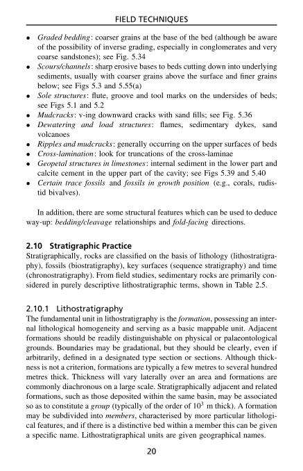
2.10.1 LithostratigraphyThe fundamental unit in lithostratigraphy is the formation, possessing an inter-nal lithological homogeneity and serving as a basic mappable unit. Adjacentformations should be readily distinguishable on physical or palaeontologicalgrounds. Boundaries may be gradational, but they should be clearly, even ifarbitrarily, defined in a designated type section or sections. Although thick-ness is not a criterion, formations are typically a few metres to several hundredmetres thick. Thickness will vary laterally over an area and formations arecommonly diachronous on a large scale. Stratigraphically adjacent and relatedformations, such as those deposited within the same basin, may be associatedso as to constitute a group (typically of the order of 103 m thick). A formationmay be subdivided into members, characterised by more particular lithologi-cal features, and if there is a distinctive bed within a member this can be givena specific name. Lithostratigraphical units are given geographical names.
20

FIELD TECHNIQUES
Table 2.5 Hierarchy of lithostratigraphic units.
Supergroup – a formal assemblage of related or superposed groups.Group – an assemblage of formations.Formation – the fundamental lithostratigraphic unit, identified by
lithological characteristics and stratigraphic position, generallytabular. Mappable at the Earth’s surface and traceable into thesubsurface. Several tens to hundreds of metres thick.
Member – a formal lithostratigraphic unit constituting a formation.Lens – a geographically restricted member occurring within a
formation.Tongue – a wedge-shaped member.Bed – a distinctive subdivision of a member; the smallest formal
lithostratigraphic unit of sedimentary rock.
To erect a lithostratigraphy yourself there are several publications whichgive details of the procedure and discuss the International Code (see Refer-ences and Further Reading). In many parts of the world, older stratigraphicnames are in use which do not conform with the International Code.
2.10.2 Sequence stratigraphyAn increasingly popular way of dividing up the stratigraphic record is on thebasis of unconformities into sequences. See Figs 2.6 and 2.7 for the basicmodels. A sequence is defined as a succession of relatively conformable,genetically related strata bounded by an unconformity or its correlative con-formity (see References and Further Reading for more information). Anunconformity (the sequence boundary) is a surface separating younger fromolder strata along which there is evidence of subaerial exposure with asignificant hiatus (type A) or of drowning (type B). It will pass laterally(basinwards) into a conformity.
A sequence can usually be divided into systems tracts (defined as a linkageof contemporaneous depositional systems, i.e. related facies, or facies associ-ation) deposited during a specific part of a cycle of relative sea-level (RSL)change, i.e., falling stage systems tract (FSST), also called forced regressive(FRST), when RSL is falling; lowstand systems tract (LST; RSL is low);transgressive systems tract (TST; RSL is rising), and highstand systems tract(HST; RSL is high) (see Figs 2.6 and 2.7). Apart from the sequence bound-ary (sb), other key surfaces are the transgressive surface (ts), which may becoincident with the sequence boundary in more proximal (landward) parts ofa basin, at the base of the TST, and the maximum flooding surface (mfs) thatseparates the TST from the HST (see Figs 2.6 and 2.7). In more distal partsof the basin, there is commonly a condensed section (cs) equivalent to the
21

FIELD TECHNIQUES
HST
HST
FSSTmfs
tssb
sb
TSTmfs
cs
cs
LST
ivfsb/ts
sand
mud
sb
mfs tsmfs
sb
sea level
HSTTSTLST
FSST
HST
Figure 2.6 Sequence stratigraphic model for siliciclastic sediments (simpli-fied), showing arrangement of systems tracts and key surfaces, and locationof sands and muds, for a ramp margin. FSST, LST, TST and HST = fallingstage, lowstand, transgressive and highstand systems tracts; ivf = incised val-ley fill; sb = sequence boundary, ts = transgressive surface, mfs = maximumflooding surface, cs = condensed section.
sb mfs HSTsb
mfs tsmfs
sb
HSTTSTLST
FSST
HST
sb/ts TST FSST
LST megabreccia
mudst.
grainst.
reef
talus
Figure 2.7 Sequence stratigraphic model for carbonate sediments (simpli-fied), showing arrangement of systems tracts and key surfaces, and locationof major facies, for a rimmed shelf margin. See Fig. 2.6 for abbreviations.
upper part of the TST, the mfs and the lower part of the HST. The sequencestratigraphic terms are defined in Table 2.6.
There are some significant differences in the sequence stratigraphic modelsfor clastics and carbonates (see Figs 2.6 and 2.7) in view of the differentcontrols on sedimentation, notably the mostly in situ generation of carbonatesediments and the imported nature of clastic sediments.
22

FIELD TECHNIQUES
Table 2.6 Hierarchy of sequence stratigraphic units
Depositional sequence: genetically related strata bounded by surfaces oferosion or non-deposition, i.e., unconformities (sequence boundaries) andtheir correlative conformities.
Key surfaces: sequence boundary, transgressive surface and maximumflooding surface, which divide sequences into systems tracts.
Sequence boundary (sb): two types:A – characterised by subaerial exposure and erosion associated withstream rejuvenation, a basinward shift of facies and onlap of overlyingstrata, often biostratigraphic gap;B – a drowning unconformity; deeper-water facies over shallow-waterfacies.
Transgressive surface (ts): marks onset of pronounced relative sea-levelrise; first significant marine flooding surface above sb, with faciesdeepening upward above. The ts may coincide with the sb in a landwarddirection.
Maximum flooding surface (mfs): marks maximum relative sea level,deepest-water facies; distal areas starved of sediment form a condensedsection (cs), overlain by shallowing-upward succession.
Systems tract (ST): a linkage of contemporaneous depositional systems.Four types are distinguished:
(1) falling stage (FSST) (also called forced regressive, FRST) – faciesdeposited during sea-level fall;
(2) lowstand (LST) – facies deposited during sea-level low;(3) transgressive (TST) – facies deposited during relative sea level rise;(4) highstand (HST) – facies deposited during sea-level high.
Parasequence set: succession of genetically related parasequences thathave a distinctive stacking pattern (e.g., thinning up); usually bounded bymajor marine flooding surfaces.
Parasequence (psq): relatively conformable succession of geneticallyrelated beds or bedsets bounded by marine flooding surfaces; typicallymetre-scale.
Marine flooding surface (fs): a surface that separates younger from olderstrata, across which there is evidence of an abrupt increase in water depth.
23
FIELD TECHNIQUES
Some sequences, especially in platform carbonates, are composed of sev-eral or many metre-scale cycles termed parasequences (defined by floodingsurfaces at their bases), and then the systems tracts are defined by thestacking patterns of the parasequences (e.g., whether they thin/thicken-upor fine/coarsen-up). See Section 8.4 for further information on how to recog-nise the key surfaces and systems tracts in the field, and what features tolook for in successions of parasequences.
Sequences within an area are generally named by letters or numbers, ora combination of both, working from the base upwards.
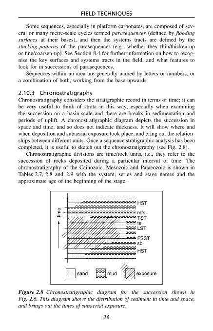
2.10.3 ChronostratigraphyChronostratigraphy considers the stratigraphic record in terms of time; it canbe very useful to think of strata in this way, especially when examiningthe succession on a basin-scale and there are breaks in sedimentation andperiods of uplift. A chronostratigraphic diagram depicts the succession inspace and time, and so does not indicate thickness. It will show where andwhen deposition and subaerial exposure took place, and bring out the relation-ships between different units. Once a sequence stratigraphic analysis has beencompleted, it is useful to sketch out the chronostratigraphy (see Fig. 2.8).
Chronostratigraphic divisions are time/rock units, i.e., they refer to thesuccession of rocks deposited during a particular interval of time. Thechronostratigraphy of the Cainozoic, Mesozoic and Palaeozoic is shown inTables 2.7, 2.8 and 2.9 with the system, series and stage names and theapproximate age of the beginning of the stage.
HST
TST
LST
FSSTsb
ts
mfs
HST
sand mud exposure
time
Figure 2.8 Chronostratigraphic diagram for the succession shown inFig. 2.6. This diagram shows the distribution of sediment in time and space,and brings out the times of subaerial exposure.
24

FIELD TECHNIQUES
Table 2.7 The Cainozoic chronostratigraphical scale with approx-imate ages of the beginning of the series. Ma = millions of yearsbefore the present
System Series Stage Ma
Quaternary Holocene 0.1Pleistocene 1.7
Neogene Pliocene GelasianPiacenzianZanclean 5.5
Miocene MessinianTortonianSerravallianLanghianBurdigalianAquitanian 24
Paleogene Oligocene ChattianRupelian 34
Eocene PriabonianBartonianLutetianYpesian 54
Paleocene ThanetianSelandianDanian 65
25

FIELD TECHNIQUES
Table 2.8 The Mesozoic chronostratigraphical scale withapproximate ages of the beginning of the series
System Series Stage Ma
Cretaceous Upper MaastrichtianCampanian
SantonianConiacianTuronianCenomanian 99
Lower AlbianAptianBarremianHauterivianValanginianBerriasian 142
Jurassic Upper Tithonian(Malm) Kimmeridgian
Oxfordian 156Middle Callovian(Dogger) Bathonian
BajocianAalenian 178
Lower Toarcian(Lias) Pliensbachian
SinemurianHettangian 200
Triassic Upper RhaetianNorianCarnian 230
Middle LadinianAnisian
Lower OlenekianInduan 251
26

FIELD TECHNIQUES
Table 2.9 The Palaeozoic chronostratigraphical scale with approximateages of the beginning of the series
System Series Stage Ma
Permian Lopingian ChanghsingianWuchiapingian
Guadalupian CapitanianWordianRoadian 270
Cisuralian KungurianArtinskianSakmarianAsselian 290
Carboniferous Upper GzhelianKasimovianMoscovianBashkirian 323
Lower SerpukhovianViseanTournaisian 360
Devonian Upper FammenianFrasnian 382
Middle GivetianEifelian 395
Lower EmsianPragianLochkovian 417
Silurian Upper PridolianLudlovian 424
Lower WenlockianLlandoverian 443
Ordovician Upper AshgillianCaradocian 458
Mid Llanvirn 473Lower Arenig
Tremadocian 490
Cambrian Upper 500Middle 511Lower 545
27


3SEDIMENTARY ROCK TYPES
3.1 Principal Lithological GroupsFor the identification of sedimentary rock types in the field, the two principalfeatures to note are composition–mineralogy and grain-size. On the basisof origin, sedimentary rocks can be grouped broadly into four categories(Table 3.1).
The most common lithologies are the sandstones, mudrocks and lime-stones (which may be altered to dolomites). Other types – evaporites, iron-stones, cherts and phosphates – are rare or only locally well developed, andvolcaniclastics are important in some places.
In some cases you may have to think twice as to whether the rock iseven sedimentary in origin or not. Greywacke sandstones, for example, canlook very much like dolerite or basalt, especially in hand-specimens awayfrom the outcrop. Points generally indicating a sedimentary origin includethe presence of:
• stratification• specific minerals of sedimentary origin (e.g., glauconite, chamosite)• sedimentary structures on bedding surfaces and within beds• fossils• grains or pebbles which have been transported (that is, clasts).
3.1.1 Terrigenous clastic rocksThese are dominated by detrital grains (especially silicate minerals and rockfragments) and include the sandstones, conglomerates, breccias and mudrocks.
• Sandstones are composed of grains chiefly between 116 and 2 mm in diam-
eter (Section 3.2). Bedding is usually obvious and sedimentary structuresare common within the beds and upon the bedding surfaces.
• Conglomerates and breccias (Section 3.3), also referred to as rudites,consist of large clasts (pebbles, cobbles and boulders), more roundedin conglomerates, more angular in breccias, with or without a sandy ormuddy matrix.
Sedimentary Rocks in the Field. Maurice E. Tucker 2003 John Wiley & Sons, Ltd ISBN: 0-470-85123-6
29

SEDIMENTARY ROCK TYPES
Table 3.1 The four principal categories of sedimentary rock with the broadlithological groups.
Terrigenousclastics
Biochemical–biogenic–organic deposits
Chemicalprecipitates
Volcani-clastics
sandstones,mudrocks,conglomerates+ breccias
limestones +dolomites, coal,phosphorites,chert
ironstones,evaporites
tephra(pyroclasticdeposits),tuffs
• Mudrocks (Section 3.4) are fine-grained with particles mostly less than116 mm in diameter, and are dominated by clay minerals and silt-gradequartz. Many mudrocks are poorly bedded and also poorly exposed.Colour is highly variable, as is fossil content.
With increasing grain-size muds/mudrocks grade into sands/sandstonesand the latter into gravels/conglomerates, and there are also mixtures of allthree, of course. Figure 3.1 shows terms for mixtures of clay/silt/sand andmud/sand/gravel. Sediments consisting of a rapid interbedding of sandstonesand mudrocks are often referred to as heterolithic facies.
3.1.2 Limestones and dolomitesLimestones (Section 3.5) are composed of more than 50% CaCO3 and sothe standard test is to apply dilute hydrochloric acid (HCl); the rock will
Sand
S
cS zS
sC sZ
C zC cZ Z
0/100
25/75
50%
75/25
100/0
Sand
S
mS gS
sM sG
M gM mG G0/100
25/75
50%
75/25
100/0
Clay Silt Mud Gravel
Figure 3.1 Classification of sand (S), silt (Z) and clay (C) mixtures, wheres = sandy, z = silty and c = clayey, and sand (S), mud (M) and gravel (G)mixtures, where s = sandy, m = muddy and g = gravelly. For rocks, S issandstone, M is mudrock, Z is siltstone and G is conglomerate, and g isconglomeratic.
30

SEDIMENTARY ROCK TYPES
fizz. Many limestones are a shade of grey, but white, black, red, buff, creamand yellow are also common colours. Fossils are commonly present, in somecases in large numbers.
Dolomites (also dolostones) are composed of more than 50% CaMg(CO3)2.They react little with dilute acid (although a better fizz will be obtained ifthe dolomite is powdered first), but more readily with warm or more con-centrated acid. Alizarin red S in hydrochloric acid stains limestone pink tomauve, whereas dolomite is unstained. Many dolomites are creamy yellowor brown in colour and they are commonly harder than limestones. Mostdolomites have formed by replacement of limestone and as a result in manycases the original structures are poorly preserved. Poor preservation of fossilsand the presence of vugs (irregular holes) are typical of dolomites.
3.1.3 Other lithologiesGypsum is the only evaporite mineral (Section 3.6) occurring commonly atthe Earth’s surface, mostly as nodules of very small crystals in mudrock,although veins of fibrous gypsum (satin spar) are usually associated. Evapor-ites such as anhydrite and halite are encountered at the surface only in veryarid areas.
Ironstones (Section 3.7) include bedded, nodular, oolitic and replacementtypes. They commonly weather to a rusty yellow or brown colour at outcrop.Some ironstones feel heavy relative to other sediments.
Cherts (Section 3.8) are mostly cryptocrystalline to microcrystalline sili-ceous rocks, occurring as very hard bedded units or nodules in otherlithologies (particularly limestones). Many cherts are dark grey to black,or red.
Sedimentary phosphate deposits or phosphorites (Section 3.9) consistmostly of concentrations of bone fragments and/or phosphate nodules. Thephosphate itself is usually cryptocrystalline, dull on a fresh fracture surfacewith a brownish or black colour.
Organic sediments (Section 3.10) such as hard coal, brown coal (lignite)and peat should be familiar, and oil shale can be recognised by its smell anddark colour.
Volcaniclastic sediments (Section 3.11), which include the tuffs, are com-posed of material of volcanic origin, chiefly lava fragments, volcanic glassand crystals. Volcaniclastics are variable in colour, although many are a shadeof green through chlorite replacement. They are commonly badly weatheredat outcrop. The term pyroclastic refers to material derived directly from vol-canic activity, whereas the term epiclastic is used to refer to ‘secondary’sediments such as debris flow and fluvial deposits resulting from the rework-ing of pyroclastic material.
31

SEDIMENTARY ROCK TYPES
3.2 SandstonesSandstones are composed of five principal ingredients: rock fragments (lithicgrains), quartz grains, feldspar grains, matrix and cement. The matrix con-sists of clay minerals and silt-grade quartz, and in most cases this fine-grainedmaterial is deposited along with the sand grains. It can form from the diage-netic breakdown of labile (unstable) grains, however, and clay minerals canbe precipitated in pores during diagenesis. Cement is precipitated around andbetween grains, also during diagenesis; common cementing agents are quartzand calcite. Diagenetic hematite stains a sandstone red.
The composition of sandstone is largely a reflection of the geology andclimate of the source area. Some grains and minerals are mechanically andchemically more stable than others. Minerals, in decreasing order of stability,are quartz, muscovite, microcline, orthoclase, plagioclase, hornblende, biotite,pyroxene and olivine. A useful concept is that of compositional maturity :immature sandstones contain many unstable grains (rock fragments, feldsparsand mafic minerals). Mature sandstones consist of quartz, some feldspar andsome rock fragments, whereas supermature sandstones consist almost entirelyof quartz. In general, compositionally immature sandstones are depositedclose to the source area, whereas supermature sandstones result from long-distance transport and much reworking. The minerals present in a sandstonethus depend on the geology of the source area, the degree of weatheringthere, and the length of the transport path.
The accepted classification of sandstones is based on the percentages ofquartz (+chert), feldspar, rock fragments and matrix in the rock (Fig. 3.2).Sandstones containing an additional, non-detrital component, such as car-bonate grains (ooids, bioclasts, etc.), are referred to as hybrid sandstonesand are described in succeeding sections. The composition of a sandstone isbased on a modal analysis determined from a thin-section of the rock usinga petrological microscope and a point counter.
In the field, it is often possible to assess the composition and give thesandstone a name through close scrutiny with a hand-lens. This can be verifiedlater in the laboratory when a thin-section is available. With a hand-lens,attempt to estimate the amount of matrix present in a sandstone and thusdetermine whether it is an arenite (a clean sandstone) or a wacke (>15%matrix, a muddy sandstone).
The nature of the grains themselves is best determined from their frac-ture surface. The percentage charts in Fig. 3.3 can be used to estimate theproportions of the various constituents present.
Quartz grains will appear milky to clear and glassy (Fig. 3.4), withoutcleavage surfaces but with fresh conchoidal fractures. Quartz grains com-monly have a quartz cement overgrowth around them and this will have
32

SEDIMENTARY ROCK TYPES
quartz
quartzarenite
5%sa
25%sl
arkosicarenite
lithicarenite
greywacke
feldsp. lithic
arenites
wackes
quartzwackemudrocks
> 75%matrix
15%
increasingmatrix
feldspar rock fragments
sa: subarkose sl: sublitharenite
Figure 3.2 Classification of sandstones. Careful use of a hand-lens in thefield should enable recognition of the main sandstone types: quartz arenite,arkose, litharenite and greywacke.
2%
25%
5%
33%
10%
50%
Figure 3.3 Percentage estimation charts. Use for giving a rough estimateof the percentage of grains or bioclasts (fossils) or crystals (etc.) present inthe rock.
33

SEDIMENTARY ROCK TYPES
Figure 3.4 Close-up of surface of an aeolian sandstone (red-coloured), large-ly composed of quartz grains (clear, glassy). Note the light reflecting off somegrain surfaces; these are crystal faces of the overgrowth cement. Millimetrescale. Permian, N.W. England.
flat crystal surfaces, reflecting the light (Fig. 3.4). Feldspar grains are com-monly slightly to totally replaced by clay minerals, so they do not havethe fresh glassy appearance of quartz; they are usually white in colour,possibly pink. Cleavage surfaces and/or twin planes are usually visible onthe fracture surfaces, as they reflect the light. In many sandstones at out-crop, the feldspar grains have been dissolved out, leaving a porous, quartz-dominated, usually friable sandstone. Lithic grains (rock fragments) can berecognised by their composite nature and may show alteration (to chlorite,for example). Of the micas, muscovite is recognised by its silvery-greycolour and flaky nature, and the less common biotite by its brown-blackcolour.
Some cements in arenites can be identified in the field. Apart from theacid test for calcite, many such cements are large poikilotopic crystals, severalmillimetres to even 1 cm across, enclosing several sand grains. The cleavagefracture surfaces of such crystals are easily seen with a hand-lens, or simplywith the naked eye by getting the light to reflect off the cleavage surfaces ofthe calcite. Quartz cement usually takes the form of overgrowths on quartzgrains. Such overgrowths commonly develop crystal faces and terminations,and these too can be seen with a hand-lens, or again when the sun reflectsoff the crystal faces, so the grains sparkle.
34

SEDIMENTARY ROCK TYPES
3.2.1 Quartz arenitesCompositionally supermature and clean, these sandstones are typical of, butnot restricted to, high-energy shallow-marine environments, and also aeolian(wind-blown) sand-seas in deserts (e.g. Fig. 3.4). Sedimentary structures arecommon, especially cross-stratification, on small, medium and large scales(Section 5.3.3). Since only quartz is present, the colour of quartz arenites iscommonly white or pale grey, especially those of shallow-marine environ-ments. Aeolian quartz arenites are commonly red through the presence offinely disseminated hematite which coats grains. Quartz and calcite cementsare common.
Quartz arenites also form through leaching of a sediment, whence theunstable grains are dissolved out. Ganister, a type of soil occurring beneathcoal seams and containing rootlets (black organic streaks), forms in this way.
3.2.2 ArkosesArkoses can be recognised by the high percentage of feldspar grains, althoughat outcrop these may be altered, especially to kaolinite (a white clay mineral).Many arkoses are red or pink, in part due to the presence of pink feldsparsbut also through hematite pigmentation. Some coarse-grained arkoses looklike granites until you see the bedding. In many, grains are subangular tosubrounded and sorting is moderate; a considerable amount of matrix maybe present between grains. Relatively rapid erosion and deposition undera semi-arid climate produce many arkoses. Fluvial systems (alluvial fan,braided stream) are typical depositional environments for arkoses, especiallyif granites and granite–gneisses are exposed in the source area.
3.2.3 LitharenitesLitharenites are very variable in composition and appearance, dependinglargely on the types of rock fragment present. In phyllarenites, fragmentsof argillaceous sedimentary rock are dominant, and in calclithites, limestonefragments predominate. Lithic grains of igneous and metamorphic origin arecommon in some litharenites. In the field it is usually sufficient to identify arock as being a litharenite; a more precise classification would have to comefrom a petrographic study. Many litharenites are deltaic and fluvial sediments,but they can be deposited in any environment.
3.2.4 GreywackesGreywackes are mostly hard, light to dark grey rocks with abundant matrix.Feldspar and lithic grains are common and often clearly identifiable witha hand-lens. Although greywackes are not environmentally restricted, manywere deposited by turbidity currents in relatively deepwater basins and so
35

SEDIMENTARY ROCK TYPES
show sedimentary structures typical of turbidites (sole structures, gradedbedding and internal laminae: see Figs 8.3 and 8.10–8.12). Greywackes com-monly grade upwards into mudrocks.
3.2.5 Hybrid sandstonesThese contain one or more components that are not detrital, such as theauthigenic mineral glauconite or grains of calcite (ooids, bioclasts, etc.). Thegreensands contain granules of glauconite (a potassium iron aluminosilicate)in addition to a variable quantity of siliciclastic sand grains. Glauconite tendsto form in marine-shelf environments starved of sediment.
Calcarenaceous sandstones contain a significant quantity (10–50%) ofcarbonate grains, usually skeletal fragments and/or ooids. With more than50% carbonate grains, the rock becomes a sandy limestone. In calcareoussandstones the CaCO3 is present as the cement.
For further information on the composition and mineralogy of a sandstoneit is necessary to collect samples and study thin-sections made from them.Petrofacies, that is sandstones distinct on petrographic grounds, can be ofgreat importance in unravelling the source of the sediment and the palaeo-geography at the time. In a broad way, the composition of a sandstone doesrelate to the plate-tectonic setting of the depositional basin. See sedimentarypetrology textbooks for further information.
3.3 Conglomerates and BrecciasThe key features which are important in the description of conglomeratesand breccias are the types of clast present and the texture of the rock.See Chapter 4 for textural considerations. Other terms used for these coarsesiliciclastic sediments are rudite (simply a coarse sedimentary rock) anddiamictite – any poorly sorted terrigenous, generally non-calcareous, peb-ble–sand–mud mixture (diamicton is the term if uncemented). Mixtite hasalso been used. The term megabreccia is used for a deposit of very largeblocks (see Section 5.5.1).
On the basis of clast origin, intraformational and extraformational con-glomerates and breccias are distinguished. Intraformational clasts are pebblesderived from within the basin of deposition; many of these are fragments ofmudrock or lime mudstone liberated by penecontemporaneous erosion on theseafloor, river channel, etc., or by desiccation along a shoreline, lake margin,tidal flat, etc., with subsequent reworking (Fig. 3.5). Extraformational clastsare derived from outside the basin of deposition and are thus older than theenclosing sediment.
The variety of clasts in a conglomerate should be examined: polymic-tic conglomerates are those with several or many different types of clast;
36

SEDIMENTARY ROCK TYPES
Figure 3.5 Intraclasts (or flakes) of lime mudstone, some tabular, somerounded, in a matrix with quartz grains. Intraformational conglomerate (alsocalled flakestone). Millimetre scale. Late Precambrian, Arctic Norway.
oligomictic (or monomictic) conglomerates are those with just one typeof clast.
The nature of the extraformational clasts in a conglomerate or brec-cia is important since it can give useful information on the provenance ofthe deposit, and on the rocks exposed there at the time. For a meaningfulpebble count, several hundred should be identified, but you may have tomake do with less. If possible, undertake pebble counts on conglomeratesfrom different levels in the stratigraphic succession, and on conglomeratesfrom different parts of the region being studied. Plot the results for each
37

SEDIMENTARY ROCK TYPES
locality as a histogram or pie diagram, and for the succession as a wholeas a columnar diagram with different widths for the various clast types(Fig. 3.6). These data could show that there were changes in the nature ofrocks exposed in the source area during sedimentation and through time, asa result of uplift and erosion, or that several different areas were supplyingthe material.
For interpretations of the depositional mechanisms of pebbly–boulderysedimentary rocks, the texture is important: clast-supported conglomerates(termed orthoconglomerates) must be distinguished from matrix-supportedconglomerates (paraconglomerates, also called diamictites or diamicton ifuncemented) (see Section 4.4). The shape, size and orientation of the pebblesshould be measured (Section 4.6), as well as the thickness and geometry ofthe beds and any sedimentary structures.
Conglomerates and breccias are deposited in a range of environments, butparticularly glacial, alluvial fan and braided stream. Clasts in a glacial deposit,often a diamictite, may have striations and scratches. Fluvial conglomeratesmay be reddened, or interbedded with floodplain mudrocks with soils. Con-glomerates deposited in beach and shallow-marine environments may contain
50
00 50 100% 0 cm
maximum clastsize
50
10
20
30
met
res
40
50%
25
0A
A
B
B
C
A B C
C
Figure 3.6 Presentation of clast data: clast composition (three types: A, B, C)plotted stratigraphically from observations at 5 m intervals in a conglomeraticsuccession, and as a histogram and a pie diagram, and maximum clast sizeplotted stratigraphically.
38

SEDIMENTARY ROCK TYPES
marine fossils and the pebbles may have borings and encrustations of calcare-ous organisms. Conglomerates may also be deposited in deep water, throughdebris flows and high-density turbidity currents, in which case they are usuallyassociated with mudrocks containing deepwater fossils.
Some specific types of breccia include collapse breccia, formed throughdissolution of limestone as in a karstic breccia or evaporite (see Section 4.6and 5.4.1.5), meteorite impact breccia, volcanic breccia (see Section 3.11),and tectonic breccia.
3.4 MudrocksMudrocks are the most abundant of all lithologies but they are often diffi-cult to describe in the field because of their fine grain-size. Mudrock is ageneral term for sediments composed chiefly of silt (4 to 62 µm) and clay(<4 µm) sized particles. Siltstone and claystone are sediments dominatedby silt- and clay-grade material respectively. Claystones can be recognisedby their extremely fine grain-size and usually homogeneous appearance;mudrocks containing silt or sand have a ‘gritty’ feel when crunched betweenyour teeth.
Shales are characterised by the property of fissility, the ability to splitinto thin sheets generally parallel to the bedding; many shales are laminated(Section 5.3.1). Mudstones are non-fissile and many have a blocky or massivetexture. Argillite refers to a more indurated mudrock, whereas slate possessesa cleavage. A marl is a calcareous mudrock. Mudrocks grade into sandstones.Terms for clay–silt–sand mixtures and mud–sand–gravel mixtures are givenin Fig. 3.1.
Mudrocks are chiefly composed of clay minerals and silt-grade quartzgrains; other minerals may be present. Organic matter may reach several percent and higher, and with increasing carbon content the mudrock becomesdarker and eventually black in colour. A distinctive smell is produced bystriking an organic-rich rock with a hammer. Hit the rock and smell the endof the hammer.
Nodules commonly develop in mudrocks, usually of calcite, dolomite,siderite or pyrite (Section 5.5.6). Fossils are present in many mudrocks,including microfossils, which need to be extracted in the laboratory. How-ever, macrofossils are commonly broken and compressed through compactionof the mudrock during burial.
Mudrocks can be deposited in practically any environment, particularlyriver floodplain, lake, low-energy shoreline, lagoon, delta, outer-marine shelfand deep-ocean basin. The sedimentological context of the mudrocks, togetherwith the fossil content, are important in their environmental interpretation.
In the field, once the type of mudrock present has been ascertained, it canbe described by the use of one or two adjectives which relate to a conspicuous
39

SEDIMENTARY ROCK TYPES
Table 3.2 Features to note and look for when examining mudrocks and exam-ples of terms which can be used in their description.
Mudrock feature Possibilities and descriptive terms
A Note the colour grey, red, black, green, variegated,mottled, marmorised
B See how themudrock breaks
fissile (shale), non-fissile (mudstone),blocky, earthy, papery, cleaved (slate)
C Look forsedimentary structures
bedded, laminated, bioturbated, rootletted,massive (apparently structureless)
D Check non-clayminerals present
quartzitic, micaceous, calcareous,gypsiferous, pyritic, sideritic, etc.
E Assess the organiccontent
organic-rich, bituminous, carbonaceous,organic-poor
F Look for fossils fossiliferous, graptolitic, ostracodal, etc.
or typical feature. Note the colour, degree of fissility, sedimentary structuresand mineral, organic or fossil content (Table 3.2).
3.5 LimestonesLimestones, like sandstones, can be described in only a limited way in thefield; the details are revealed through studies of thin-sections and peels.Three components make up the majority of limestones: carbonate grains;lime mud/micrite (micro-crystalline calcite) and cement (usually calcite spar,also fibrous calcite). The principal grains are bioclasts (skeletal grains/fossils),ooids, peloids and intraclasts. Many limestones are directly analogous to sand-stones, consisting of sand-sized carbonate grains which were moved aroundon the seafloor, whereas others can be compared with mudrocks, being fine-grained and composed of lithified lime mud (i.e., micrite or lime mudstone).Some limestones are formed in situ by the growth of carbonate skeletons as inreef limestones (Section 3.5.3), or through trapping and binding of sedimentby microbial mats (formerly algal mats) as in stromatolites and microbiallaminites (Section 5.4.5).
The carbonate grains of modern sediments are composed of aragonite,high-Mg calcite and low-Mg calcite. Limestones are normally composed ofjust low-Mg calcite, with original aragonite components replaced by calcite,and the magnesium lost from original high-Mg calcite. Aragonite grains arevery rarely preserved, and then only as fossils within impermeable mudrocksrather than limestones. In some limestones there are holes (moulds) whereoriginally aragonitic fossils and ooids have been dissolved out (e.g., Figs 3.7
40

SEDIMENTARY ROCK TYPES
Figure 3.7 Close-up of oolitic limestone where ooids have been dissolved out,probably because of an original metastable aragonitic mineralogy, to give anoomoldic porosity. Millimetre scale. Permian, N.E. England.
and 6.9). Other diagenetic changes important in limestones are dolomitisationand silicification.
Although the majority of carbonate successions in the geological recordare shallow-marine in origin (supratidal to shallow subtidal), limestones arealso deposited in deeper water as pelagic and turbidite beds, and in lakes.Nodular limestones, which may also be laminated and peloidal, can developin soils and are called calcretes or caliches (Section 5.5.6.2).
3.5.1 Limestone componentsSkeletal grains (bioclasts/fossils) are the dominant constituents of many Phan-erozoic limestones. The types of skeletal grain present depend on envi-ronmental factors during sedimentation (e.g. water temperature, depth andsalinity) as well as on the state of invertebrate evolution and diversity at thetime. The main organism groups contributing skeletal material are the mol-luscs (bivalves and gastropods), brachiopods, corals, echinoderms (especiallythe crinoids), bryozoans, calcareous algae, stromatoporoids and foraminifera.Other groups of lesser or local importance are the sponges, crustaceans (espe-cially ostracods), annelids (serpulids) and cricoconarids (tentaculitids). Thecarbonate skeletons have different original mineralogies, and the preservationof the bioclasts in the limestone depends on this. Grains originally of low-Mg calcite (e.g. brachiopods), some bivalves (e.g. scallops, oysters, mussels)
41

SEDIMENTARY ROCK TYPES
and serpulids are generally very well preserved; those of high-Mg calciteoriginally (e.g. crinoids, bryozoans, calcareous red algae, rugose corals) areusually well preserved but may show some alteration. Bioclasts originally ofaragonite (e.g. many bivalves, gastropods, scleractinian corals, green algae)are usually poorly preserved; they may be dissolved out completely and pre-served as moulds (see Fig. 6.9) or consist of coarse calcite crystals (sparite).
In the field, you should try to identify the main types of carbonate skeletonin the limestone. If these are present as macrofossils, it should be possible toidentify them to the group level, and then determine the genus/species back inthe laboratory. The carbonate skeletons may be sufficiently well preserved orabundant to allow useful palaeoecological observations to be made (see Chap-ter 6). One feature to check is whether the skeletal material is in its growthposition and, if so, whether this was providing a framework for the limestone,or acting as a baffle to trap sediment, or encrusting and binding the sediment.These features are typical of reef-rocks and buildups (Section 3.5.3).
Figure 3.8 Close-up of ooids withthe concentric structure clearlyvisible in some cases. Millimetrescale. Jurassic, N.E. England.
Ooids are spherical to subspherical grains, generally in the size range0.2 to 0.5 mm, but reaching several millimetres in diameter. Structureslarger than 2 mm are referred to as pisoids or pisolites. Ooids consistof concentric coatings around a nucleus, usually a carbonate particleor quartz grain (Fig. 3.8). Most modern marine ooids are composed
of aragonite, but ancient ones weregenerally originally calcitic in mid-Palaeozoic and Jurassic–Cretaceoustimes and aragonitic (now calcite) atother times.
Peloids are subspherical to elon-gate grains of micrite (lime mud) gen-erally less than 1 mm in length. Theyare faecal in origin or altered bioclasts.
Intraclasts are fragments of re-worked carbonate sediment. Many areflakes up to several centimetres long,derived from desiccation of tidal-flatcarbonate muds or penecontempora-neous erosion, especially by storms.The intraformational conglomerates(Fig. 3.5) formed in this way aresometimes called edgewise conglomer-ates or flakestones. Aggregates consistof several carbonate grains cementedtogether during sedimentation.
42

SEDIMENTARY ROCK TYPES
Micrite is the matrix to many bioclastic limestones and the main con-stituent of fine-grained limestones. It consists of carbonate particles mostlyless than 4 µm in diameter. Much modern carbonate mud, the forerunnerof micrite, is biogenic in origin, forming through the disintegration of car-bonate skeletons such as calcareous algae. The origin of micrite in ancientlimestones is obscure and it is often difficult to eliminate direct or indirectinorganic precipitation.
Sparite (sparry calcite, calcite spar) is a clear, sometimes white and coarse,equant cement precipitated in the pore space between grains and in largercavity structures. It is mostly a burial cement, although it can be a near-surfacefreshwater precipitate. Fibrous calcite is also a cement, coating grains andfossils and lining cavities. This is generally of marine origin and is common inreef-rocks (Fig. 3.9), mud mounds and stromatactis structures (see Fig. 5.42and Section 5.4.1.3).
3.5.2 Limestone types
Figure 3.9 Fibrous calcite marinecement coating blocks of reef mate-rial. Note the growth layeringwithin the cement. The central partof the cavity is filled with cal-cite spar. Millimetre scale. Triassic,Austrian Alps.
Three schemes are currently usedfor the description of limestones(see Table 3.3), although the Dunhamscheme is now more widely used.Common limestone types using theFolk notation are biosparite, biomi-crite, oosparite, pelsparite and pelmi-crite. Biolithite refers to a limestonewhich has formed through in situgrowth of carbonate organisms (asin a reef) or through trapping andbinding of sediment as by micro-bial mats to form stromatolites (seeSection 5.4.5).
Common limestones in the Dun-ham scheme are grainstones, pack-stones, wackestones and mudstones ;the term boundstone is equivalent tobiolithite. Several other terms havebeen introduced for reef-rocks, asvarieties of boundstone: framestone,bafflestone and bindstone (Fig. 3.10).The term framestone refers to a lime-stone where the carbonate skeleton forms a framework. Robust branchingcorals commonly produce framestones. Bafflestone refers to a limestonewhere organisms have acted as a baffle to trap sediment; more delicate
43

SEDIMENTARY ROCK TYPES
Table 3.3 Schemes for the classification of limestones: (A) on dominantgrain-size; (B) on dominant constituent – prefixes can be combined ifnecessary, as in bio-oosparite (after R.L. Folk); and (C) on dominant texture(after R.J. Dunham).
A
2 mm 62 µmcalcirudite calcarenite calcilutite
B
Limestone type
Dominant constituent Sparite cement Micrite matrix
ooids oosparite oomicritepeloids pelsparite pelmicritebioclasts biosparite biomicriteintraclasts intrasparite intramicrite
in situ growth: biolithite fine-grained limestone + fenestrae: dismicrite
C
Textural features Limestone type
mud absent grainstonegrain
supported packstonecarbonate
mud >10% grains wackestonepresent mud
supported <10% grains mudstone
components organically bound during deposition: boundstone
branching skeletons, including bryozoans or solitary, vertically growingorganisms such as rudist bivalves and some corals, commonly form baf-flestones. Platey corals, sheet-like calcareous algae and microbial mats formbindstones.
For coarse fossiliferous, bioclastic limestones, the terms rudstone wherethe bioclasts (>2 mm diameter) are in contact, and floatstone where the
44

SEDIMENTARY ROCK TYPES
floatstone rudstone bafflestone bindstone framestone
Figure 3.10 Sketches showing appearance of coarse limestones (most grains>2 mm), floatstone and rudstone, and three types of boundstone (reef-rock).
bioclasts are supported by finer sediment, are commonly used (Fig. 3.10).One final type of reefal limestone is one dominated by marine cement: acementstone.
The percentage of the various components present in a limestone can beestimated by reference to the charts in Fig. 3.3.
In the field, careful observation of the texture and composition, often withthe use of a hand-lens, can establish the type of limestone present. The maintypes of grain can usually be recognised with little difficulty, although infiner-grained limestones it may be impossible to distinguish between matrixand cement.
In the field the surface of a limestone is commonly weathered, especiallyby the action of lichens, so that the features of the rock are difficult to see.It is often necessary to examine a fresh surface, and then if you lick the rockand look with a hand-lens, you will be able to see the grains clearly.
Limestones commonly have small holes (vugs) through to large cav-erns developed within them through the effects of dissolution by rainwateror groundwater. Speleothems (stalactites and stalagmites) may occur withinthese cavities, and layers of laminated fibrous calcite (flowstone) often coatthe limestone surface. Do not mistake modern occurrences of these fea-tures, which typically form in humid/temperate regions, for ancient examples(palaeokarsts: see Sections 5.4.1.5 and 5.4.2). And in the same way, cementedlimestone breccias and calcareous soils (calcretes /caliches), formed in recenttimes, are common in limestone areas, especially in semi-arid regions; again,do not mistake these for ancient examples (see Section 5.5.6.2).
The texture of the limestone (Chapter 4) should be described, but bear inmind that the size, shape, roundness and sorting of skeletal grains in a carbon-ate sediment is a reflection of the size and shape of the original skeletons aswell as the degree of agitation and reworking in the environment. Althoughpractically all sedimentary structures of siliciclastics can occur in limestones,there are some which are restricted to carbonate sediments (Section 5.4).
45

SEDIMENTARY ROCK TYPES
As noted in Chapter 2, the textural scheme of Dunham can be used directlyfor the graphic logging of limestones (see Fig. 2.3).
3.5.3 Reef limestonesThese are broadly in situ accumulations or buildups of carbonate material.Reef limestones have two distinctive features: a massive unbedded appear-ance (Figs 3.11, 3.12, 5.83 and 5.84), and a dominance of carbonate skeletons,commonly of colonial organisms, with many in their growth position. Someskeletons may have provided a framework within and upon which otherorganisms grew. Cavity structures filled with internal sediment and cementare common; if the cements are fibrous calcite they are probably marine inorigin (Fig. 3.9).
Reef limestones have a variety of geometries, but two common formsare patch reef, small and discrete structures (Fig. 3.12), circular to elongate
Figure 3.11 A reef margin composed of massive unbedded boundstones onthe left with flank beds (to the right) of reef debris showing an original depo-sitional dip. Height of reef 5 metres. Upper Cretaceous, northern Iraq.
46

SEDIMENTARY ROCK TYPES
Figure 3.12 Small patch reef consisting of massive coral colonies and con-trasting with bedded bioclastic limestones below. Jurassic, N.E. England.
in plan, and barrier reef, a generally larger, usually elongate structure withlagoonal limestones behind (to landward) and reef-debris beds basinward.Bioherm refers to a local carbonate buildup and biostrome to a laterallyextensive buildup, both with or without a skeletal framework. Associatedwith many reef limestones are beds of reef-derived debris; these may berudstones, floatstones or grainstones/packstones. With barrier reefs and largerpatch reefs especially, there is commonly a talus apron in front of or aroundthe reef, termed fore-reef or reef-flank beds (Fig. 3.11, also Fig. 5.83). Thesebeds were often deposited on a steep to gentle slope and so show an originaldepositional dip (see clinoforms, Section 5.3.3.14).
One more particular type of carbonate buildup is the mud mound (for-merly reef knoll), consisting largely of massive lime mudstone (micrite),usually with no obvious skeletal framework organisms. Scattered skeletaldebris may be present, together with cavity structures such as stromatac-tis (Section 5.4.1.3), containing marine sediments and cements. Some mudmounds have prominent dipping flank beds; in some cases these are rich incrinoidal debris. Mud mounds typically occur within deeper-water strata, andmost are of Palaeozoic age.
With all carbonate buildups, it is their massive nature which will be imme-diately apparent, contrasting with adjacent or overlying well-bedded lime-stones. Many reef-rocks have very variable textures, so the terms in Fig. 3.10
47

SEDIMENTARY ROCK TYPES
may apply to different areas of the same reefal limestone. In addition, thedescriptive term to apply may depend on the scale of observation; a reefmay be mainly a floatstone with local areas of framestone containing smallpatches of bindstone and cementstone.
Many carbonate buildups are the result of complex interactions betweenorganisms, so verify which organisms were responsible for the buildup’sconstruction (e.g., corals, bryozoans, stromatoporoids and rudist bivalves),which were playing a secondary but still important role of encrusting orbinding the framework (e.g., calcareous algae and serpulids), and which weresimply using the reef for shelter or as a source of food (e.g., brachiopods,gastropods and echinoids). There may also be evidence of bioerosion in reef-rocks; skeletons may be perforated by borings from lithophagid bivalves,serpulids or clionid sponges (see Section 5.6.2).
Within many reefs there is a clear organisation of the organisms up throughthe buildup. Reefs commonly initiate on bioclastic banks and shoals – moundsof skeletal debris (grainstone/rudstone), with tabular and plate-like colonialorganisms growing above (a stabilisation stage generating bindstones/baffle-stones). These create the reef (colonisation stage) and the fauna may becomemore varied (diversification stage) with framestones/bindstones. The organ-isms in a reef commonly show a variety of growth forms, reflecting theenergy/water depth of the environment and sedimentation rate (see Fig. 3.13).
Examine the colonial fossils in the reef; sketch their shapes and see ifthere are any changes up through the reef.
3.5.4 DolomitesThe majority of dolomites, especially those of the Phanerozoic, have formedby replacement of limestones. This dolomitisation can take place soon afterdeposition, i.e., penecontemporaneously and notably upon high intertidal–supratidal flats in semi-arid regions, or later during shallow-burial or deeper-burial diagenesis. For facies analysis it is important to try to decide whichtype of dolomite is present.
Early-formed, peritidal dolomite is typically very fine-grained and is asso-ciated with structures indicative of supratidal conditions: desiccation cracks(Section 5.3.6), evaporites and their pseudomorphs (Section 3.6), microbiallaminites (Section 5.4.5) and fenestrae (Section 5.4.1.2). Fine-grained dolo-mites like these usually preserve the structures of the original sedimentvery well.
Later diagenetic dolomitisation can vary from local replacement of cer-tain grains, or just the lime–mud matrix and not the grains, or just burrows,or it may affect the whole limestone bed, the formation or just a particularfacies. In some cases, just originally aragonitic and high-Mg calcite grains(bioclasts/ooids) are dolomitised, and originally calcitic (low-Mg) fossils
48

SEDIMENTARY ROCK TYPES
GROWTH FORMENVIRONMENT
sedimentationrate
waveenergy
delicatebranching highlow
thin, delicateplate-like lowlow
columnar highmoderate
domal lowmod-high
robust, strong,branching moderatemod-high
tabular lowmoderate
encrusting lowvery high
Figure 3.13 Different growth forms of colonial organisms (e.g., corals,stromatoporoids, rudist bivalves, calcareous algae), reflecting the localenvironment.
(e.g. brachiopods or oysters) are unaffected. Rhombs of dolomite may bescattered through the limestone and weather out on the surface, giving aspotted appearance (Fig. 3.14). Rhombs of dolomite may be seen concen-trated along stylolites. The dolomite may occur in veins cutting through thelimestone, or in vugs – irregular holes lined with dolomite crystals. In thesecases other minerals, such as calcite, fluorite or galena, may be associated.
Dolomite of burial origin, which commonly occurs in vugs and veins, maybe of the baroque or saddle type (also called pearl spar); this dolomite hascurved crystal faces (use a hand-lens to see), maybe with steps, prominentcleavage, and a pink colour from the presence of a little iron.
Many limestones are pervasively dolomitised, and then there is commonlyan obliteration of the original structure of the sediment, so that fossils arepoorly preserved and sedimentary structures ill-defined. With some dolomitesthe dolomitisation relates to tectonic structures; for example, the dolomitemay occur adjacent to a fault (up which the dolomitising fluids migrated) or to
49

SEDIMENTARY ROCK TYPES
Figure 3.14 Dolomite rhombs (white) scattered in fine-grained limestone(grey). Millimetre scale. Cretaceous, French Alps.
major joints. The dolomitisation may be restricted to a particular stratigraphiclevel or certain facies, or relate to a certain stratigraphic horizon, such asoccurring beneath an unconformity.
Some Precambrian dolomites show little evidence of replacement andmay be of primary origin. They show all the features of limestones, althoughstromatolites (Section 5.4.5) are especially common.
On the degree of dolomitisation, carbonate rocks can be divided into fourcategories: limestones (up to 10% dolomite), dolomitic limestone (10–50%dolomite), calcitic dolomite (50–90% dolomite) and dolomite (90–100%dolomite).
3.5.5 DedolomitesDedolomites are limestones formed by the replacement of dolomite. Mostcommonly this takes place near the surface, and in some cases it is a weath-ering effect. However, it may also occur in association with the dissolutionof evaporites interbedded with dolomites. In some instances, unusual growthforms of calcite, such as large radiating fibrous calcite concretions (‘cannon-balls’), have developed within the dolomites.
50

SEDIMENTARY ROCK TYPES
3.6 EvaporitesMost gypsum at outcrop is very finely crystalline and occurs as white topink nodular masses within mudrocks (which are commonly red) or asclosely packed nodules with thin stringers of sediment between (chicken-wire texture) (Fig. 3.15). Irregular and contorted layers of gypsum form theso-called enterolithic texture. Nodular and enterolithic textures are typicalof gypsum-anhydrite precipitated in a marine sabkha (supratidal) environ-ment, so that other peritidal sediments may be interbedded (e.g., microbiallaminites/stromatolites, fenestral lime mudstones/dismicrites), or in a conti-nental sabkha, where fluvial and aeolian sediments may be associated.
Beds of gypsum may also consist of large (up to a metre or more) twinnedcrystals (selenite), normally arranged vertically (Fig. 3.16). This type of gyp-sum is typical of shallow-subaqueous precipitation.
Gypsum can be reworked by waves and storms to form gypsarenite, whichdisplays current structures, and resedimented to form turbidites and slumps.Gypsum interlaminated with organic matter or calcite is typical of subaqueous(deeper water) precipitation.
Veins of fibrous gypsum (satin spar ) are common in mudrocks associatedwith gypsum deposits. Most ancient gypsum exposed at the surface is actu-ally secondary gypsum (alabastrine gypsum) formed by the replacement ofanhydrite or primary gypsum. It can form centimetre-sized crystals.
Figure 3.15 Nodular (chicken-wire) gypsum (probably originally anhydrite)with thin clay seams between nodules. Central nodule 15 cm across. Triassic,Spain.
51

SEDIMENTARY ROCK TYPES
Figure 3.16 Selenite, a variety of gypsum with large twinned crystals.Millimetre scale. Miocene, Cyprus.
Distinctive crystals of gypsum, typically several centimetres in length andcolourless, are common in mudrocks which originally contained pyrite. Thelatter has been oxidised through near-surface weathering.
Evaporites have commonly been dissolved out of a sediment to leavea very vuggy rock. They may also be replaced by other minerals and sogive rise to pseudomorphs of the original evaporite crystal or nodule. Thesecan be recognised in the field but confirmation may require thin-sections.Halite pseudomorphs are readily identified by their cubic shape and hoppercrystal form (Fig. 3.17). The lozenge, lenticular and swallow-tail shapes ofgypsum crystals are distinctive (Fig. 3.18). Nodules of anhydrite and gyp-sum can be replaced by a variety of minerals, in particular calcite, quartzand dolomite. The outside of such nodules typically has a cauliflower-likeappearance (Fig. 3.19). Geodes may form where crystals, especially of calcite
52

SEDIMENTARY ROCK TYPES
Figure 3.17 Halite pseudomorphs,recognised by their cubic shapeand depressed (hopper) crystalfaces. Millimetre scale. Jurassic,S. England.
or quartz, have grown inwards fromthe outside of the original nodule, butthe whole vug has not been filled(Fig. 3.19).
Where evaporites have dissolvedaway, the overlying strata have oftencollapsed. If disrupted and brecciatedbeds occur in a section, a carefulsearch may reveal evidence for theformer presence of evaporites. Suchcollapse breccias have angular clasts,where some fitting back together maybe possible, poor sorting of clasts,and little matrix. Evaporite residuesusually consist of clayey, sandy sedi-
Figure 3.18 Calcite pseudomorphsafter gypsum, recognised by theirlenticular shape. Millimetre scale.Jurassic, S. England.
ments, with dispersed clasts. Dedolo-mites are commonly associated withevaporite dissolution horizons.
In areas of quite severe tec-tonic deformation, evaporite beds arecommonly the horizons along whichmajor and minor thrusts develop. Oneparticular type of rock that developsin this situation is a dolomitic/calciticcellular breccia. It usually has a box-work texture, from the dissolutionof evaporite and other clasts, andit is a yellowish/buff/creamy colour.The French term cargneule (thereare other spellings) is frequentlyused for this distinctive tectono-sedimentary rock.
3.7 IronstonesA great variety of sedimentary rocks is included under the term ironstoneand there is much variety too in the minerals present (Table 3.4).
Precambrian banded iron-formations (BIFs) are usually thick and later-ally extensive deposits characterised by a fine chert–iron mineral lamina-tion. Phanerozoic ironstones are mostly thin successions of limited arealextent, interdigitating with normal-marine sediments. Many such ironstonesare oolitic and ooids can be composed of hematite (red), berthierine-chamosite
53

SEDIMENTARY ROCK TYPES
Figure 3.19 Geode composed of quartz formed by replacement of an anhy-drite nodule. Millimetre scale. Tertiary, Iran.
Table 3.4 Main types of iron-rich sedimentary rock.
1. Chemical iron-rich sedimentsA: Cherty iron-formation: iron minerals include hematite,magnetite, siderite, commonly in a fine lamination alternating withchert, but other varieties; mostly PrecambrianB: Ironstone: textures similar to limestone with oolitic varietiestypical; iron minerals include chamosite-berthierine, goethite,hematite; mostly Phanerozoic
2. Iron-rich mudrocksA: Pyritic mudrocks: pyritic nodules and laminae, often in blackor bituminous shales, usually marineB: Sideritic mudrocks: mostly nodules in organic-rich mudrocks;often non-marine
3. Other iron-rich depositsA: Fe–Mn oxide-rich sediments: in oceanic facies, oftenassociated with pillow lavas, hydrothermal activity or pelagiclimestonesB: Iron-rich laterites and soils: often developed atunconformities, on lavasC: Bog-iron ores: rarely preserved in rock recordD: Placer deposits, especially with magnetite and ilmenite
54

SEDIMENTARY ROCK TYPES
(green), goethite (brown) and, rarely, magnetite (black). Other common iron-stones are hematitic limestones, where hematite has impregnated and replacedcarbonate grains, and berthierine-chamositic, sideritic or pyritic mudrocks.All these types can be identified in the field, but later confirmation may benecessary in the laboratory.
With ironstones, interest has focused on the depositional environment andcontext, and so it is worth examining any fossils contained in the iron-richbeds and in adjacent strata. Check whether the fossils indicate normal-marineor hyposaline (brackish-water) conditions (see Section 6.3.2). Many iron-stones were formed in sediment-starved situations, in some cases in relativelydeep water (outer shelf). Look at the facies above and below the ironstoneto see if there is any suggestion that the ironstone accumulated at a time ofmaximum water depth within the succession. Otherwise treat the ironstonelike any other lithology and look at its texture and sedimentary structures.
A different type of ironstone is one where grains of iron mineral, especiallymagnetite, are concentrated by waves and currents into laminae and beds.These placer deposits occur especially within sandstones and conglomeratesdeposited in fluvial and shoreline environments. They are easily recognisedas black laminae of well-sorted grains.
The iron minerals siderite and pyrite commonly form early diageneticnodules in mudrocks and other lithologies (see Section 5.5.6). Siderite ismore typical of brackish-water muds and pyrite of marine muds. The sideritenodules are usually weathered brown on the outside but are a steel-greycolour inside. They are common in coal-measure successions, especially inseatearths (palaeosoils).
Iron and other metals are enriched in sediments associated with pillowlavas. They are usually red and brown fine-grained mudrocks. Ferroman-ganese nodules and encrustations of bioclasts and lithoclasts occur in pelagiclimestones and mudrocks but are relatively rare. They have generally formedon the seafloor in areas of strong currents. Fe–Mn impregnation of sedimentand crusts may occur on hardground surfaces in pelagic limestones.
Iron-rich soils, known as laterites, are extensively developed in tropicalregions and are readily recognised by their rich, deep red/brown colour. Theyvary from soft and earthy to rock hard, and may show pisolitic textures. Theydo occur in the geological record, but they are not common.
3.8 ChertsTwo varieties of chert are distinguished: bedded and nodular (Figs 3.20and 3.21).
Most bedded cherts are found in relatively deepwater successions and areequivalent to the radiolarian and diatom siliceous oozes of the modern oceanfloors. The chert beds are usually some 3–10 cm thick, with thin (<1 cm)
55

SEDIMENTARY ROCK TYPES
Figure 3.20 Bedded chert withshaley partings. Carboniferous,S. France.
shale partings between (Fig. 3.20).With a hand-lens on a fresh fracturesurface (conchoidal fracture is typi-cal), you can sometimes see the radi-olarians in a chert sample as minuteround specks about 1
4 – 12 mm across;
a thin-section is required to checktheir presence. Although many bedsof chert appear massive they can pos-sess cross-lamination and graded bed-ding (Sections 5.3.3 and 5.3.4) as aresult of reworking on the seaflooror resedimentation into deeper water.Look at weathered surfaces for thesefeatures. Some bedded cherts are
associated with pillow lavas and are part of ophiolite suites, whereas othersoccur in successions with no volcanic associations at all.
Nodular cherts are common in limestones and some other lithologies andform by diagenetic replacement. In some cases there is a nucleus, such asa fossil (echinoid, sponge, etc.) around which replacement has proceeded;in others the nodules occur regularly spaced at particular horizons. Flint isa popular name for chert nodules occurring in Cretaceous chalks. In manycases the flint has precipitated within burrow systems (Fig. 3.21) which were
Figure 3.21 Nodular chert (flint), formed within crustacean burrow fills inchalk. Cretaceous, E. England.
56

SEDIMENTARY ROCK TYPES
originally filled with sediment a little coarser than the surrounding chalk.Silica for many chert nodules is derived from dissolution of sponge spiculesor siliceous plankton.
3.9 Sedimentary Phosphate Deposits (Phosphorites)The calcium phosphate mineral in these relatively rare deposits is mostly fine-grained collophane, present as vertebrate bone fragments and fish scales (bothof these may have a shiny black appearance), phosphatised fossils, peloids,coated grains and nodules (usually a dull black colour) (see Fig. 3.22). Thenodules could be coprolites but they may also form by replacement of car-bonate mud, grains and siliceous microfossils.
The precipitation of phosphate and the phosphatisation of sediment andfossils are commonly the result of high nutrient supply, perhaps associ-ated with upwelling, and low rates of sediment influx. Reworking is alsoimportant in the formation of many sedimentary phosphate deposits, so thatthey commonly form at times of increased current activity and erosion,as can be associated with a sea-level rise and transgression, for example,when the quite dense phosphatic grains/clasts are concentrated into bedsand lenses. Bone beds are usually formed in this way. Phosphatised peb-bles and fossils can also be associated with hardgrounds (Fig. 5.43), whichmay themselves be impregnated with phosphate. Such hardgrounds occur
Figure 3.22 Phosphate bed composed of phosphate nodules and phospha-tised fossils. The dark specks in the lime mudstone sediment are grains ofglauconite (actually dark green). Specimen 10 cm across. Mid-Cretaceous,French Alps.
57

SEDIMENTARY ROCK TYPES
within chalks and they may occur upon shallow-water carbonates at drown-ing unconformities (Section 8.4.5.1). The green mineral glauconite is presentin some phosphate deposits.
3.10 Organic-Rich DepositsPeat, brown coal (lignite), hard coal and oil shale are the main organic deposits.Bitumen and other semi-solid/solid hydrocarbons do occur rarely within sand-stones and limestones, and along fault and joint planes. The organic depositsare divided into a humic group, those formed through in situ organic growth,chiefly in swamps, marshes and bogs, and a sapropelic group, where theorganic matter has been transported or deposited from suspension. Most coalsbelong to the humic group whereas oil shales are sapropelic in origin.
The term rank refers to the level of organic metamorphism of a coal; anumber of properties, such as carbon and volatile content, can be used tomeasure rank, but these require laboratory analysis.
Peat generally contains much moisture and the vegetal material may stillbe recognisable in hand-specimens. It does burn, of course. Peat is formingat the present time in mires, which include lowmoor and highmoor locations,and in swamps and marshes around lakes and along shorelines. Highmoorpeat is dominated by mosses, especially sphagnum, and retains much water,mostly from rainfall rather than the watertable (hence the term raised peatbog or blanket peat). There is usually little mineral matter or sediment inthis peat, although the acid porewaters can leach sediment and rock belowor nearby, giving hydrated iron oxide precipitates. Lowmoor (fen) peat formsfrom a more diverse vegetation, including sedges, reeds and shrubs, and sois more woody. It forms close to the watertable; porewaters are less acid andthere is often sediment present, mostly clays.
Some plant material is still recognisable in soft brown coal ; in hard browncoal there are few plant fragments visible but the coal is still relatively soft,dull and brown. Brown coals contain much moisture when freshly dug andcan be either earthy or compact. These brown coals are common in Tertiaryand some older formations. Bituminous hard coals are black and hard withbright layers. They break into cuboidal fragments along the cleat (prominentjoint surfaces) and make your fingers dirty. These coals are well developed inPermo-Carboniferous strata. Anthracite is bright and lustrous with conchoidalfracture. It is generally found where coal has been affected by metamorphism,or more tectonic deformation and higher heat flow.
Cannel coal and boghead coal are sapropelic deposits which chiefly accu-mulated in lakes. They are massive, fine-grained, unlaminated sediments,which possess a conchoidal fracture. Cannel coal can be carved.
Oil shales contain more than a third inorganic material, chiefly clay butit may be carbonate. They are usually finely laminated and some can be cut
58

SEDIMENTARY ROCK TYPES
with a knife into thin shavings which curl, like wood shavings. They aremostly lacustrine in origin.
3.11 Volcaniclastic DepositsThis class of sedimentary rock includes the pyroclastic deposits and epiclas-tic deposits (reworked ‘secondary’ volcanic sediments). Tephra is a generalterm used for pyroclastic deposits, the material fragmented by explosive vol-canic activity. Tephra consist of (a) pyroclasts, i.e., pyroclastic fragmentsthat include juvenile (fresh) lumps of lava and glass (pumice or scoria)which fragment to give glass shards; (b) crystals (phenocrysts), especiallyof quartz and feldspar; and (c) lithic fragments consisting of pieces of lavafrom earlier eruptions (non-juvenile) and of country rock. The componentsof volcaniclastic deposits are given in Table 3.5.
Pyroclastic deposits are often emplaced at high temperatures. Recogni-tion features include carbonised wood, pink/red coloration due to thermaloxidation, dark coloration due to finely disseminated microlites of magnetite,radial cooling joints, gas-escape structures (including fossil fumarole pipes,vertical structures a few centimetres in width filled with coarse ash), weldingtogether of grains, and streaked-out and flattened pumice fragments.
Table 3.5 Main types of pyroclastic material occurring in volcaniclasticdeposits.
Pumice: light-coloured, low-density (if modern), vesiculated lavafragments, acid magma, mm–dm in size. Vesicles may contain calcite,zeolite or clay minerals
Scoria: dark-coloured equivalent of pumice
Glass shards: small grains of solidified glass, sub-mm in size, formedby vesiculation and fragmentation
Glassy matrix: plastic deformation textures around hard clasts, hardand splintery, welded if hot and soft when deposited
Fiamme: compressed pumice fragments, hot and soft when deposited,mm–cm in size
Accretionary lapilli: concentrically laminated spheres of ash,2–20 mm in diameter
Lithic clasts: non-juvenile lava fragments and country rock clasts, solidwhen deposited, resistant to deformation, mm–m in size
Phenocrysts: crystals that grew in the magma, mm-size
59

SEDIMENTARY ROCK TYPES
Table 3.6 Classification of volcaniclastic grains and sediments on grain-size.
Volcaniclasticgrains
Size Volcaniclasticsediment terms
(tephra)
bombs – ejected fluid coarse agglomerateblocks – ejected solid – 256 mm – volcanic breccia
fine64 mm
coarse– 16 mm –
lapilli medium lapillistone– 4 mm –
fine2 mm
very coarse– 1 mm –
coarseash – 0.5 mm –
medium– 0.06 mm –
fine
tuff
vitric
lithic
crystal
Figure 3.23 Accretionary lapilliand ash in lapilli-tuff deposit. Cen-timetre scale. Ordovician, N.W.England.
On the basis of grain-size, thepyroclasts are divided into ash, lapilli,blocks and bombs (Table 3.6). Theterm pumice refers to light-colouredvesicular glassy rock of rhyoliticcomposition, and scoria is used fordarker pieces, still vesicular, generallyof andesitic or basaltic composition.Pumice has a low density and canfloat on water. The vesicles in theselava fragments may be filled withcalcite (clear), zeolite (white) or clayminerals (green).
Accretionary lapilli are small, concentrically laminated spheres, 2–20 mm in diameter (like ooids), of finevolcanic ash, in some cases around a
60

SEDIMENTARY ROCK TYPES
nucleus of a coarse ash grain (Fig. 3.23). They commonly formed in wet(phreatic or phreatomagmatic) eruption columns and by fallout from steam-rich plumes.
Volcanic bombs are common in volcaniclastic successions and consistof large, usually rounded, randomly distributed ‘blobs’ of lava, which maydepress or rupture the bedding (bomb sags), or be deformed into strangeshapes if they were still soft when they landed. Based largely on shape,spindle, bread-crust and cow-dung bombs can be distinguished.
3.11.1 Pyroclastic depositsThree types are distinguished in terms of origin (Table 3.7).
3.11.1.1 Pyroclastic fall depositsThese include subaerial and subaqueous (submarine or sublacustrine) fallouttephra. They are characterised by a gradual decrease in both bed thicknessand grain-size away from the site of eruption. Beds are typically well sortedand normally graded. However, they are frequently reworked by currents andwaves if deposited in water, or wind if subaerial, and thus may show cross-or planar lamination (strictly these would then be epiclastic deposits). Largerfragments of pumice may occur on top of the beds if they floated beforebeing deposited. These deposits can be spread over wide areas and are usefulfor stratigraphic correlation, forming marker beds. Pyroclastic fall depositsmantle the topography, with layers of roughly constant thickness over bothhills and valleys (Fig. 3.24).
3.11.1.2 Pyroclastic flow depositsThese are the product of hot gas/solid high-concentration density currents,which may travel at velocities of 20–100 m s−1. One common pyroclasticflow deposit is an ignimbrite, produced by a violent plinian eruption, whichgenerally occurs in subaerial situations, although the flows may continueinto the sea or a lake. Ignimbrites are characterised by their homogeneous
Table 3.7 Main types of volcaniclastic sediment (and depositional process).
A pyroclastic fall deposit: graded tuff (subaqueous/subaerial fallout)B pyroclastic flow deposit: includes ignimbrite (pumice and ash flow)C pyroclastic surge deposit (base-surge deposit)D lahar deposit (volcanic mudflow)E hyaloclastite (fragmentation of basaltic lava through contact with
water)
61

SEDIMENTARY ROCK TYPES
pyroclastic fall deposit
pyroclastic surge deposit
pyroclastic flow deposit
Figure 3.24 Different geometries of pyroclastic deposits.
appearance with little sorting of the finer ash particles, so they lack internalstratification. Coarse lithic clasts in the bed may be normally graded (sizedecreasing upward) whereas large pumice clasts (which are very light at thetime of eruption) may show reverse grading (size increasing upward), orbe concentrated at the top of the bed. Flattened and stretched fragments ofpumice (termed fiamme) and glass shards indicate the soft (and hot) nature ofthe vesiculated and fragmented melt during transport (Fig. 3.25). Many ign-imbrites show welding in the central-to-lower part; here ash particles mergeto form a denser, less porous rock compared with the upper and lower partsof the bed. A subplanar foliation, termed eutaxitic texture, may develop herefrom the aligned fiamme. In its extreme, the rock is entirely glassy (vitro-phyric). Lithic fragments in the deposit resist deformation and the hot plasticglassy material is deformed around them. Some ignimbrites have a colum-nar jointing, also indicating that they were still hot on deposition. Typicalthicknesses of an ignimbrite deposit are 1 m to 10 m or more. The flowsare topographically controlled and so the deposits fill valleys and depres-sions (Fig. 3.24).
3.11.1.3 Pyroclastic surge depositsThese result from highly expanded turbulent gas–solid density currentswith low particle concentrations. Phreatomagmatic and phreatic eruptions
62

SEDIMENTARY ROCK TYPES
Figure 3.25 Ignimbrite showing streaked-out pumice fragments (fiamme).Millimetre scale. Tertiary, New Zealand.
Figure 3.26 Base-surge and pyroclastic fall deposits. The base-surge tuffoccurs in the upper part and shows well-developed bedding (antidune cross-bedding) with flow to the right. The pyroclastic air-fall deposits occur in thelower part. Metre staff. Quaternary, Germany.
involve steam and generate base-surge deposits. They are characterised bywell-developed unidirectional sedimentary bedforms (dunes) giving cross-stratification (Fig. 3.26), pinch-and-swell features and antidune cross-bedding(Section 5.3.3.15), since they are deposited by very fast-flowing ash-ladensteam flows. Individual laminae are generally well sorted. These depositstend to blanket the topography, although they do thicken into the depressions(Fig. 3.24). There is a complete gradation between high-particle concentrationpyroclastic flows and low-particle concentration pyroclastic surges.
63

SEDIMENTARY ROCK TYPES
3.11.2 Epiclastic depositsSpecific types of these reworked primary volcanic sediments include lahardeposits and hyaloclastites.
3.11.2.1 Lahar depositsThe flows that deposit these sediments form a continuum between high-temperature flows in which hot pyroclastic material is mixed with water(such as streams or snowmelt) during an eruption, and low-temperature flowsrepresenting the remobilisation by water of already deposited cool pyroclas-tic material. Lahars are mudflows containing principally volcanic materialwhich typically deposit large volcanic fragments in a fine ashy matrix. Theyare characterised by a matrix-support fabric with large ‘floating’ clasts ofvolcanic material (Section 4.4). Lahars usually have a larger range of blocksand boulders, many of which are lithic clasts, rather than juvenile material,and an absence of any indications of very hot temperatures, compared withthe hot pyroclastic flow deposits described above. Lahar deposits, by virtueof their muddy matrix, tend to be more consolidated than pyroclastic flowdeposits with their ashy matrices.
3.11.2.2 HyaloclastitesThese form where lava is extruded into water and the rapid chilling andquenching cause fragmentation of the lava. These deposits typically consistof lava chips and flakes, a few millimetres to a few centimetres across.The chilled glassy lava is commonly altered by hydration to a yellow-greenmaterial called palagonite. Hyaloclastites lack any sorting or stratificationclose to the site of eruption, but they can be reworked and resedimented toshow sedimentary structures as with any other clastic sediment. Hyaloclastitesare typical of submarine basaltic volcanism.
3.11.3 Studying young volcaniclastic successionsIt is generally easier to study young volcaniclastic deposits, since it will bemore obvious initially that are volcanic and they are then likely to preservemany of the original features, such as the local and regional variations inbed thickness, bed geometry and internal structures. If they are poorly lithi-fied, then the grain-size distributions can be studied (by sieving back in thelaboratory) to provide useful information on the depositional processes (seetextbooks). The different types of volcaniclastic deposit noted above maythen be readily identified. There may well be lava flows interbedded with alltheir typical features (see below). Needless to say, working in areas of recentvolcanic activity can be very dangerous.
64

SEDIMENTARY ROCK TYPES
3.11.4 Studying ancient volcaniclastic sedimentsIn more ancient strata, where erosion after deposition may have removedmuch of the volcanic edifice, or tectonic and metamorphic processes haveobscured primary features or caused recrystallisation, it may be necessary touse a basic lithological approach to document the features, i.e., noting thegrain-size, composition, degree of welding, bed thickness, sedimentary struc-tures, colour, etc., as in any other sedimentary rock, before the depositionalprocesses can be unravelled.
In ancient volcanic successions, it can be difficult to distinguish tuffsfrom lavas; brecciated lavas may be confused with agglomerates, and flow-banded lavas with ignimbrites. Typical features of lava flows are (a) columnarjointing in the central part (as with some ignimbrites!), (b) a blocky texture,(c) brecciated basal parts and tops, (d) vesicles concentrated towards the tops,and (e) weathered, reddened and/or rubbly upper surfaces. Ignimbrites do notusually have basal breccias.
3.11.5 Volcaniclastic successionsIt is useful to document the upward changes through a volcaniclastic suc-cession; make graphic logs and look for long-term changes in volcaniclasticdeposit type.
• Are there changes in the proportion of pyroclastic fallout versus flowdeposits? Are there systematic upward bed thickness changes in the tuffs,reflecting increasing or decreasing volcanic activity?
• Are there long-term changes in the composition of the volcanic mate-rial – more acid to more basic, for example (examine the glass fragmentsfor colour changes, the degree of vesiculation and phenocryst composi-tion)?
• Is there any evidence for compositional zonation or stratification withinthe magma chamber, increasing phenocryst content within a single flowdeposit, for example? There may be an upward increase (or decrease) inthe proportion of non-volcanic interbeds.
In some volcaniclastic successions there is a packaging of the fallout andflow deposits, like cycles in other sedimentary strata. In a complete ‘classic’pyroclastic eruption episode, the succession deposited begins with air-fall tuff,overlain by a pyroclastic surge deposit, and then a pyroclastic flow deposit,before more air-fall tuff at the top of the unit (Fig. 3.27).
65

SEDIMENTARY ROCK TYPES
fine tuff
pyroclasticflow deposit
pyroclasticsurge deposit
air-fall tuff
Figure 3.27 A complete ‘classic’ pyroclastic succession from one major erup-tion. Fumarole pipes filled with coarse ash are shown towards the top of theflow deposits, from escaping gas.
66

4SEDIMENTARY ROCK TEXTURE
4.1 IntroductionSediment texture is concerned with the grain-size and its distribution,morphology and surface features of grains, and the fabric of the sediment.Induration and weathering (Section 4.7) and colour (Section 4.8) are alsoconsidered in this chapter.
Texture is an important aspect in the description of sedimentary rocks andcan be useful in interpreting the mechanisms and environments of deposition.It is also a major control on the porosity and permeability of a sediment. Thetexture of many sedimentary rocks can only be studied adequately with amicroscope and thin-sections. With sand and silt-sized sediments you cannotdo much more in the field than estimate grain-size and comment on thesorting and roundness of grains. With conglomerates and breccias, the size,shape and orientation of grains can be measured accurately in the field; inaddition, surface features of pebbles and the rock’s fabric can be examinedquite easily. A checklist for a sediment’s texture is given in Table 4.1.
4.2 Sediment Grain Size and SortingThe most widely accepted and used grain-size scale is that ofUdden–Wentworth (Table 4.2). For more detailed work, phi units (φ) areused; phi is a logarithmic transformation: φ = − log2 S, where S is grain-sizein millimetres.
For sediments composed of sand-sized particles, use a hand-lens to deter-mine the dominant grain-size class present; it is usually possible to distinguishbetween very coarse/coarse, medium and fine/very fine sand classes. Compar-ison can be made with the sand sizes depicted in Fig. 4.1. For finer-grainedsediments, chew a tiny piece of the rock; silt-grade material feels grittybetween the teeth compared with clay-grade material, which feels smooth.
With chemical rocks such as evaporites, recrystallised limestones anddolomites, it is crystal size that is being estimated, rather than grain-size.Terms for crystal size are given in Table 4.3.
For accurate and detailed work, particularly on siliciclastic sediments,various laboratory techniques are available for grain-size analysis, includ-ing sieving of poorly cemented sedimentary rocks or modern sediments,
Sedimentary Rocks in the Field. Maurice E. Tucker 2003 John Wiley & Sons, Ltd ISBN: 0-470-85123-6
67

SEDIMENTARY ROCK TEXTURE
Table 4.1 Checklist for the field examination of sedimentary rock texture.
1. Grain-size, sorting and size-gradingEstimate in all lithologies: see Table 4.2 and Figs 4.1, 4.2 and 5.34.In conglomerates, measure maximum clast size and bed thickness;check for correlation.
2. Morphology of constituent grains(a) Shape of grains: see Fig. 4.4 (important for clasts in conglom-
erates); look for facets on pebbles, and striations.(b) Roundness of grains: see Fig. 4.5.
3. Fabric(a) Look for preferred orientation of elongate clasts in conglomer-
ates and fossils in all lithologies (Figs 4.6, 6.6 and 6.7); measureorientations and plot rose diagram (see Chapter 7).
(b) Look for imbrication of clasts or fossils (Figs 4.6 and 4.7).(c) Examine matrix–grain relationships, especially in conglomerates
and coarse limestones; deduce whether the sediment is matrix-supported or grain-supported (see Fig. 4.8).
(d) Look for deformation of pebbles (compacted, fractured, split,pitted).
point-counting of thin sections of rocks, and sedimentation methods (seeReferences and Further Reading).
In the field only a rough estimate can be made of sorting in a sand-gradesediment. Examine the rock with a hand-lens and compare it with the sketchesin Fig. 4.2.
The grain-size of a sediment may fine or coarsen upwards through thebed to give a graded bed. Normal graded bedding is most common with thecoarsest particles at the base, but inverse (or reverse) grading also occurs,with a coarsening upward of grains. Often this is just in the lower part of abed and then normal grading takes over. In some instances a bed may showno grain-size sorting at all. Composite graded bedding denotes a bed withseveral fining-upward units within it. See Section 5.3.4 for more information.
In a broad sense, the grain-size of siliciclastic sediments reflects thehydraulic energy of the environment: coarser sediments are transported anddeposited by faster flowing currents than finer sediments; mudrocks tend toaccumulate in quieter water. The sorting of a sandstone reflects the deposi-tional process, and this improves with increasing agitation and reworking. Incontrast, the grain-size of carbonate sediments generally reflects the size ofthe organism skeletons and calcified hardparts which make up the sediment;
68

SEDIMENTARY ROCK TEXTURE
Table 4.2 Terms for grain-size classes(after J.A. Udden and C.K. Wentworth)and siliciclastic rock types. For sand–silt–clay mixtures and gravel–sand–mud mix-tures see Fig. 3.1.
256 mm
64
4
2 mm
1
500 mm
250
125
63 microns
32
16 SILT
8
4 microns
boulders conglomerates(rounded clasts)
breccias(angular clasts)
andcobbles
pebbles
granules
v. coarse
coarse
fine
v. fine
v. coarse
coarse
medium
fine
SILTSTONE
SAND medium SANDSTONE
CLAY CLAYSTONE
MUDROCKStypes:mudstoneshalemarlslate
these can also be affected by currents, of course. Sorting terms can be appliedto limestones, but bear in mind that some limestone types, for example ooliticand peloidal grainstones, are well sorted anyway so that the sorting terms donot necessarily reflect the depositional environment.
For grain-size and sorting of conglomerates and breccias see Section 4.6.
4.3 Grain MorphologyThe morphology of grains has three aspects: shape (or form), determined byvarious ratios of the long, intermediate and short axes; sphericity, a measureof how closely the grain shape approaches that of a sphere; and roundness,concerned with the curvature of the corners of the grain.
For shape, four classes are recognised – spheres, discs, blades and rods,based on ratios involving the long (L), intermediate (I) and short (S) axes (see
69

SEDIMENTARY ROCK TEXTURE
fine
medium
granulespebb
les
coar
se
very coarse
0.25
mm
2 m
m
0.5 mm
4 mm
1 mm
Figure 4.1 Chart for estimating grain-size of sands: medium sand is 0.25 to0.5 mm in diameter, coarse sand is 0.5 to 1 mm in diameter, etc. Place a smallpiece of the rock or some grains scraped off the rock in the central circle anduse a hand-lens to compare and deduce the size.
very well sorted well sorted moderately sorted poorly sorted
Figure 4.2 Charts for visual estimation of sorting.
Figs 4.3 and 4.4). These terms are useful for describing clast shape in con-glomerates and breccias and can be applied with little difficulty in the field.The shape of pebbles is largely a reflection of the composition and any planesof weakness, such as bedding/lamination, cleavage or jointing in the rock.Rocks of a very uniform composition and structure, such as many granites,
70

SEDIMENTARY ROCK TEXTURE
Table 4.3 Informal terms for describing crys-talline rocks.
very coarsely crystalline1.0 mm
coarsely crystalline0.5 mm
medium crystalline0.25 mm
finely crystalline0.125 mm
very finely crystalline0.063 mm
microcrystalline0.004 mm
cryptocrystalline
sphere
S = I = L
blade
S < I < L
rod
S = I < L
disc
S < I = L
Figure 4.3 The four common shapes of pebbles; S, I and L are the short,intermediate and long diameters, respectively.
dolerites and thick sandstones, will give rise to equant/spherical pebbles; thin-bedded rocks will generally form tabular and disc-shaped clasts, and highlycleaved or schistose rocks, such as slates, schists and some gneisses, willgenerally form bladed or rod-shaped pebbles.
Formulae are available for the calculation of sphericity and roundness (seetextbooks). Roundness is more significant than sphericity as a descriptiveparameter and for most purposes the simple terms of Fig. 4.5 are sufficient.These terms can be applied to grains in sandstones and to pebbles in con-glomerates. In general, the roundness of grains and pebbles is a reflection oftransport distance or degree of reworking.
The roundness terms are less environmentally meaningful for grains in alimestone since some, such as ooids and peloids, are well rounded to beginwith. Skeletal grains in a limestone should be checked to see if they arebroken or their shape has been modified by abrasion.
71

SEDIMENTARY ROCK TEXTURE
SPHERES
compact
DISCS BLADES RODS
extreme
0 0.33 0.66 10
0.3
0.5
0.7
1
disc-rod index (L−I)/(L−S)
shap
e in
dex √I
LS
Figure 4.4 The four classes of grain or clast shape based on the ratios of thelong (L), intermediate (I) and short (S) diameters.
low
sph
eric
ity
hig
h sp
heric
ity
very angular angular subangular subrounded rounded well-rounded0 1 2 3 4 5 6
Figure 4.5 Categories of roundness for sediment grains. For each categorya grain of low and high sphericity is shown.
4.4 Sediment FabricFabric refers to the mutual arrangements of grains in a sediment. It includesthe orientation of grains and their packing. Fabrics may be produced duringsedimentation or later during burial and through tectonic processes.
72

SEDIMENTARY ROCK TEXTURE
In many types of sedimentary rock a preferred orientation of elongateparticles can be observed. This can be shown by prolate pebbles in a con-glomerate or breccia, and fossils in a limestone (e.g., Fig. 6.6), mudrock (e.g.,Fig. 6.7) or sandstone; such features are visible in the field. Many sandstonesshow a preferred orientation of elongate sand grains but microscopic exami-nation is required to demonstrate this.
Preferred orientations of particles arise from interaction with the depo-sitional medium (water, ice, wind), and can be both parallel to (the morecommon), and normal to, the flow direction (Fig. 4.6). Measurement of peb-ble, fossil or grain orientations can thus indicate the palaeocurrent direction(Section 7.3.4). With pebbles it is best to measure clasts that have a clearelongation; a length to width ratio of more than 3:1 is acceptable. Preferredorientations can also be tectonically induced, so if you are working in anarea of moderate deformation, also measure fold axes, cleavage and lin-eations. Pebbles may be rotated into the tectonic direction. Look for pressureshadows and the development of fibrous minerals at the ends of the pebble.
Tabular and disc-shaped pebbles or fossils commonly show imbrication.In this fabric, they overlap each other (like a pack of cards), dipping inan upstream direction (Figs 4.6 and 4.7). This can be a useful texture fordeducing the palaeocurrent direction (see Section 7.3.4).
The amount of fine-grained matrix and the matrix–grain relationship affectthe packing and fabric of a sediment and are important in interpretations ofdepositional mechanism and environment. Where grains in a sediment arein contact, the sediment is grain-supported ; matrix can occur between thegrains, as can cement (Figs 4.7 and 4.8). Where the grains are not in contact,the sediment is matrix-supported (Figs 4.8 and 4.9). Also look at the matrixbetween the large clasts in coarser sediments; this may be well sorted or
parallel to current normal to current imbricated
current
Figure 4.6 Orientations of grains and pebbles: parallel to current, normal tocurrent, and imbricated.
73

SEDIMENTARY ROCK TEXTURE
Figure 4.7 Conglomerate with a clast-support fabric, crude normal gradedbedding and well-developed imbrication (elongate, flat clasts dipping downto the left) indicating transport to the right, overlying a massive sandstone(10 cm thick) of well-sorted medium to very coarse sand. Fluvial facies,Permian, S.W. England.
Clast-supported,bimodal,matrix well sorted
Clast-supported,polymodal,matrix poorly sorted
Matrix-supported,polymodal,poorly sorted
Figure 4.8 Grain fabric and sorting: clast-support with well-sorted andpoorly sorted matrix, and matrix support.
poorly sorted (i.e., the sediment as a whole may be bimodal or polymodal ingrain-size, Fig. 4.8).
With sandstones and limestones, grain-support fabric with no mudgenerally indicates reworking by currents and/or waves/wind, or depositionfrom turbulent flows where suspended sediment (mud) is separated from
74

SEDIMENTARY ROCK TEXTURE
Figure 4.9 Conglomerate (also a diamictite) with a matrix-support fabricand subangular to subrounded pebbles. Tillite (ancient glacial deposit), LatePrecambrian, Norway.
coarser bed load. Limestones with matrix support-fabric, such as awackestone (Table 3.3), mostly reflect quiet-water sedimentation. Rudstoneand floatstone are coarse limestones with a grain-support and matrix-supportfabric respectively (see Fig. 3.10 and Fig. 4.8).
Fabric of conglomerates and breccias is discussed further in Section 4.6.
4.5 Textural MaturityThe degree of sorting, the roundness and the matrix content in a sand-stone contribute towards the textural maturity of the sediment. Texturallyimmature sandstones are poorly sorted with angular grains and some matrix,whereas texturally supermature sandstones are well sorted with well-roundedgrains and no matrix. Textural maturity generally increases with the amountof reworking or distance travelled; for example, aeolian and beach sand-stones are typically mature to supermature, whereas fluvial sandstones are lessmature. Textural maturity is usually matched by a comparable compositionalmaturity (Section 3.2). It should be remembered that diagenetic processescan modify depositional texture. An estimate of the textural maturity of asandstone can be made in the field by close examination with a hand-lens.
75

SEDIMENTARY ROCK TEXTURE
4.6 Texture of Conglomerates and BrecciasThere is no problem with measuring the grain-sizes of these coarser sedimentsin the field; a ruler or tape measure can be used. With conglomerates andbreccias, it is the maximum clast size that is usually measured. There areseveral ways of doing this, but one method is to take the average of the 10largest clasts in a rectangular area of 0.5 × 0.5 metres. It can be useful toestimate modal size as well for a conglomerate bed. Measure the long axesof 20–30 pebbles; plot a histogram and determine the size of the dominantpebbles. Maximum clast size is used as a parameter, since with many ruditesthis is a reflection of the competency of the flow.
It is also useful to measure the bed thickness of conglomerates. This mayvary systematically up through a succession, increasing or decreasing upward,reflecting an advance or retreat of the source area. With some transportingand depositing processes (mudflows and stream floods, for example) thereis a positive correlation between maximum particle size and bed thickness.With braided stream conglomerates there is no such relationship.
Maximum particle size and bed thickness generally decrease down thetransport path. Measurements of maximum particle size and bed thicknessfrom conglomerates over a wide area or from a thick vertical succession mayreveal systematic variations which could be due to changes in the environmentand the amount and type of sediment being supplied, and these may reflectfundamental changes involving climate or tectonics.
For the grain-size distribution in coarse sediments, sorting terms ofFig. 4.2 can be applied, but in many cases these terms are inappropriatesince the distribution is not unimodal. Many conglomerates are bimodal orpolymodal in their grain-size distribution if the matrix between pebbles isconsidered (see Fig. 4.8). It is also important to check grain-size variationsthrough a conglomerate bed. Normal size-grading of pebbles through a bedis common but inverse/reverse grading can also occur, particularly in thebasal part (see Fig. 5.34 and Section 5.3.4). In some rudites, such as thosedeposited by debris flows, large clasts occur towards the top of the bed; thesewere carried there by the upward buoyancy of the flow.
The shape and roundness of pebbles can be described by reference toFigs 4.3 and 4.4. With regard to shape, some pebbles of desert and glacialenvironments possess flat surfaces, facets arising either from wind abrasion(such pebbles are known as ventifacts or dreikanters) or from glacial abrasion.A characteristic feature of pebbles in a glacial deposit is the presence ofstriations, although they are not always present. Taken over a large area orup a thick succession, there may be significant changes in the degree ofroundness of pebbles. This can be related to the length of the transport path.
The shape of pebbles may be modified during burial and through tectonicdeformation. Clasts of mudrock, especially those of intraformational origin,
76

SEDIMENTARY ROCK TEXTURE
may be folded, bent, deformed and fractured during compaction. Where thereis a lot of overburden, there may be sutured contacts (stylolites) between clastsas a result of pressure dissolution (Section 5.5.7), or one pebble may be forcedinto another to produce a concave pit. During more intense deformation andmetamorphism, pebbles may be flattened and stretched out.
Attention should be given to the fabric of the conglomerate; in particularcheck for preferred orientations of elongate clasts (if possible measure severaltens, or more, of long axes) and look for imbrication of prolate pebbles(long axes parallel to current and dipping upstream, Figs 4.6 and 4.7). Ifexposures are very good then the dip angle of the long axis relative to thebedding can be measured to give the angle of imbrication. In fluvial andother conglomerates a normal-to-current orientation is produced by rollingof pebbles, while the parallel-to-current orientation arises from a sliding ofpebbles. In glacial deposits, the orientation of clasts is mostly parallel to thedirection of ice movement. Glacial diamictites which have been subjected toperiglacial conditions of freeze and thaw may contain split boulders.
Some limestone breccias are the result of in situ brecciation processes;this is the case with some karstic breccias (see Section 5.4.1.5), brecciatedhardgrounds and tepees (Sections 5.4.3 and 5.4.4), brecciated soils (calcretes,Section 5.5.6.2) and collapse breccias formed through dissolution of intra-stratal evaporites (Section 3.6).
Examine the pebble–matrix relationship (Section 4.4). Pebble-support fab-ric (Figs 4.7 and 4.8) is typical of fluvial and beach gravels; matrix-supportfabric (Figs 4.8 and 4.9) is typical of debris-flow deposits (debrites), whichmay be subaerial (as in alluvial fans or in volcanic areas, Section 3.11)or submarine (as in slope aprons/fans). Glacial deposits, tills and tillites,deposited directly from glacial ice, are also generally matrix-supported anddebris flow deposits are commonly associated (the terms diamict/diamictonand diamictite are often applied to muddy gravel/conglomerate with someglacial connection).
4.7 Induration and Degree of WeatheringThe induration or hardness of a sedimentary rock cannot be quantified easily.It depends on the lithology, as well as the degree of cementation, the burialhistory, stratigraphic age, etc. Induration is an important concept since itdoes affect the degree of weathering of a rock, along with topography, climateand vegetation. A well-indurated rock in the subsurface may be rendered veryfriable at the surface as a result of weathering. Calcite cements in a sandstone,for example, are easily dissolved out at the surface, as are feldspar grains andcalcareous fossils. Some sandstones at surface outcrop are friable and full ofholes from decalcification. A qualitative scheme can be used for describinginduration (Table 4.4).
77

SEDIMENTARY ROCK TEXTURE
Table 4.4 A qualitative scheme for describing the induration of a sedimen-tary rock.
Term Description
unconsolidated loose, no cement whatsoeververy friable crumbles easily between fingersfriable rubbing with fingers frees numerous grains; gentle
blow with hammer disintegrates samplehard grains can be separated from sample with
pen-knife; breaks easily when hit with hammervery hard grains are difficult to separate with a pen-knife;
difficult to break with hammerextremely hard sharp hard hammer blow required; sample breaks
across most grains
4.7.1 Rock exposures and outcropsThe way in which sedimentary rocks appear at outcrop can give useful infor-mation on sediment lithology, but in particular on the vertical changes up thesuccession. Mudrocks are generally less well exposed than sandstones andlimestones, since they are usually less well indurated and soils develop moreeasily upon them. Thus in cliff and mountainside exposures, sandstones andlimestones tend to stand out relative to mudrocks which weather or are cov-ered in vegetation. Sandstones and limestones generally give rise to steeperslopes than mudrocks. Bedding-normal joints and fractures are more commonin sandstones and limestones than in mudrocks and give rise to vertical cliffsin horizontal strata. The presence of cycles in a succession, and the fining-upward or coarsening-upward of sediments in a sequence, are commonlyrevealed as a result of this differential response to weathering.
Look at a cliff or hillside carefully; the nature of the outcrop, even ifpoor, the slope profile and distribution of vegetation, may all give importantclues to the lithologies present and upward trends and changes.
4.7.2 Weathering and alteration of sediments and rocksThe state of weathering of sediments and rocks is an important aspect ofdescription and can give useful information on climate, present and past,and length of exposure, as well as on the degree of alteration and loss ofstrength for engineering purposes (see British Standards Institution, 1981).All sediments and rocks are weathered to various extents when exposed to theelements at the Earth’s surface and eventually soils with A and B zones maydevelop with vegetation. The weathered zone beneath the soil is zone C. Theweathering of rocks leads to discoloration, decomposition and disintegration.
78

SEDIMENTARY ROCK TEXTURE
I
II
III
IV
V
VI
Bsoil
wea
ther
ed z
ones
A
Figure 4.10 Weathering zones ofbedrock beneath a soil (also seeTable 4.5).
Weathering features can be lookedfor in present-day exposures as well asin rocks beneath unconformities. Thesoils above weathered zones may wellbe removed by subsequent erosion andso not preserved. Weathering featuresand soils seen at outcrop today maynot be currently forming but be relict,the result of processes in the past whenclimate was different.
Weathering of sediments and rockstakes place through both mechanicaland chemical processes with climatemostly controlling the degree of each.Mechanical weathering results in theopening of fractures and discontinuitiesand the creation of new ones, at boththe rock and crystal scale. Chemicalweathering causes discoloration of therock, alteration of grains, as in manysilicate minerals to clays, and dissolutionof grains – especially carbonates (fossilsand calcite cements), and even the rockitself, leading to potholes, caverns andkarst (see Section 5.4.1.5). A weatheringscale which can be adopted to yourlocal situation is shown in Table 4.5and Fig. 4.10. All degrees of weatheringmay occur in one profile, with the Aand B horizons of the soil above, or aprofile may show just the lower levelsas a result of erosion.
4.8 Colour of Sedimentary RocksColour can give useful information on
lithology, depositional environment anddiagenesis. For many purposes a simple estimate of the colour is sufficient,although it is amazing how one person’s subjective impression of colour canvary from another’s. For detailed work, a colour chart can be used; thereare several widely available, including one from the Geological Society ofAmerica based on the Munsell Colour System.
79

SEDIMENTARY ROCK TEXTURE
Table 4.5 Scale of weathering of sediment and rocks (see also Fig. 4.10).
Term Description Grade
Residualsoil
All rock material is converted to soil. The rockstructure and material fabric are destroyed.There may be a change in volume, but the soilhas not been transported significantly
VI
Completelyweathered
All rock material is decomposed and/ordisintegrated to soil. The original structure isstill largely intact
V
Highlyweathered
More than half of the rock material isdecomposed or disintegrated to a soil. Fresh ordiscoloured rock is present either as adiscontinuous framework or as corestones
IV
Moderatelyweathered
Less than half of the rock material isdecomposed or disintegrated to a soil. Fresh ordiscoloured rock is present either as acontinuous framework or as corestones
III
Slightlyweathered
Discoloration indicates weathering of rockmaterial and discontinuity surfaces. All therock may be discoloured by weathering
II
Fresh No visible sign of rock weathering; perhapsslight discoloration on major discontinuitysurfaces
I
It is obviously best to measure the colour of a fresh rock surface but, ifdifferent, also note the colour of the weathered surface. The latter can give anindication of the rock’s composition, for example, in terms of iron content.
Two factors determine the colour of many sedimentary rocks: theoxidation state of iron and the content of organic matter. Iron exists intwo oxidation states: ferric (Fe3+) and ferrous (Fe2+). Where ferric iron ispresent it is usually as the mineral hematite, and even in small concentrationsof less than 1% this imparts a red colour to the rock. The formation ofhematite requires oxidising conditions and these are frequently present withinsediments of semi-arid continental environments. Sandstones and mudrocksof these environments (deserts, playa lakes and rivers) are commonlyreddened through hematite pigmentation (developed during early diagenesis)and such rocks are referred to as ‘red beds’. Red marine sedimentary rocksare also known, however.
80

SEDIMENTARY ROCK TEXTURE
Where the hydrated forms of ferric oxide, goethite or limonite, are present,the sediment has a yellow-brown or buff colour. In many cases, yellow-brown colours are the result of recent weathering and hydration/oxygenationof ferrous iron minerals such as pyrite or siderite, or ferroan calcite orferroan dolomite.
Where reducing conditions prevailed within a sediment, the iron is presentin a ferrous state and generally contained in clay minerals; ferrous ironimparts a green colour to the rock. Green colours can develop throughreduction of an originally red sediment, and vice versa. With red- and green-coloured deposits see if one colour, usually the green, is restricted to, say,coarser horizons or is concentrated along joint and fault planes; this wouldindicate later formation through the passage of reducing waters through themore permeable layers or conduits.
Organic matter in a sedimentary rock gives rise to grey colours and withincreasing organic content to a black colour. Organic-rich sediments generallyform in anoxic conditions. Finely disseminated pyrite also gives rise to a darkcolour. Black pebbles, which are reworked out of soil horizons and may bethe result of forest fires, are commonly associated with unconformities andexposure horizons.
Other colours such as olive and yellow can result from a mixing of thecolour components. Some minerals have a particular colour and if present inabundance can impart a strong colour to the rock; for example, glauconiteand berthierine-chamosite give rise to green-coloured sediments. Anhydrite,although not normally present at outcrop, may be a pale blue colour.
Some sediments, especially mudrocks, marls and fine-grained limestones,may be mottled, with subtle variations in grey, green, brown, yellow,pink or red colours. This may be due to bioturbation and the differentialcolouring of burrows and non-bioturbated sediment (burrow mottling),generating an ichnofabric (Section 5.6.1), or it may be due to pedogenicprocesses: water moving through a soil causing an irregular distributionof iron oxides/hydroxides and/or carbonate, and/or the effect of roots andrhizoturbation (Section 5.6.4). The term marmorisation has been applied tothis process. Colour mottling is common in lacustrine and floodplain mudsand marls, especially sediments of palustrine facies (lake sediments stronglyaffected by pedogenesis).
Many sedimentary rocks show curious colour patterns which are similar tothose produced in chromatography or loosely referred to as Liesegang rings:swirling, curved and cross-cutting patterns which are oblique to the bedding.The colours are usually shades of yellow and brown, even red, from variationsin the contents of iron oxides and hydroxides. These may form at any timeafter deposition, although they are often related to weathering, and relate tothe passage and diffusion of porewater through the sediment and precipitation
81

SEDIMENTARY ROCK TEXTURE
Table 4.6 The colour of sedimentary rocks and probable cause.
Colour Probable cause
red hematiteyellow/brown hydrated iron oxide/hydroxidegreen glauconite, chloritegrey some organic matterblack much organic mattermottled partly leachedwhite/no colour leached
or dissolution of minerals. The common colours of sedimentary rocks andtheir cause are shown in Table 4.6.
82

5SEDIMENTARY STRUCTURES AND GEOMETRY
OF SEDIMENTARY DEPOSITS
5.1 IntroductionSedimentary structures are important attributes of sedimentary rocks. Theyoccur on the upper and lower surfaces of beds as well as within beds. They canbe used to deduce the processes and conditions of deposition, the directions ofthe currents which deposited the sediments (Chapter 7), and in areas of foldedrocks, the way-up of the strata (see Section 2.9). An index of sedimentarystructures as presented in this book is given in Table 5.1.
Sedimentary structures are very diverse and many can occur in almost anylithology. Sedimentary structures develop through physical and/or chemicalprocesses before, during and after deposition, and through biogenic pro-cesses. It is convenient to recognise five categories of sedimentary structure:erosional (Section 5.2), depositional – all sediment types (Section 5.3), depo-sitional – especially in limestones (Section 5.4), post-depositional/diagenetic(Section 5.5) and biogenic (Section 5.6).
The geometry of sedimentary deposits is an important feature at all scalesand is discussed in Section 5.7, as are the relationships between sedimen-tary units.
5.2 Erosional StructuresThe common structures of this group are the flute, groove and tool markswhich occur on the undersurfaces (soles) of beds, scour structures in generaland channels.
5.2.1 Flute castsFlute casts are readily identifiable from their shape (Fig. 5.1). In plan, on thebedding undersurface, they are elongate to triangular (‘heel-shaped’) witheither a rounded or a pointed upstream end; they flare in a downstreamdirection. In section they are asymmetric, with the deeper part at the upstreamend. Flute marks vary in length from several to tens of centimetres. Flutesform through erosion of a muddy sediment surface by eddies in a passingturbulent current and then the marks are filled with sediment as the flow
Sedimentary Rocks in the Field. Maurice E. Tucker 2003 John Wiley & Sons, Ltd ISBN: 0-470-85123-6
83

SEDIMENTARY STRUCTURES AND GEOMETRY
Table 5.1 Index of sedimentary structures: main types and location of descrip-tion and/or figures in this book.
Bedding surface structures
Ripples : look at symmetry/asymmetryand crest shape: current, wave or windripples? Section 5.3.2; Figs 5.9–5.12Shrinkage cracks : desiccation orsyneresis cracks: Section 5.3.6;Figs 5.36, 5.37Parting lineation (primary currentlineation): Section 5.3.1.3; Fig. 5.7Rainspot impressions : Section 5.3.7;Fig. 5.38Tracks and trails : crawling, walking,grazing, resting structures: Section5.6.2; Tables 5.7, 5.9; Figs 5.70, 5.71
Internal sedimentary structures
Bedding and lamination: Section 5.3.1;Table 5.2; Figs 5.4–5.8Graded bedding : normal and reverse:Section 5.3.4; Figs 4.7, 5.34Cross-stratification: many types:Table 5.3; Section 5.3.3Massive bedding : is it really massive?Section 5.3.5; Fig. 5.35Slumps and slumped bedding :Section 5.5.1; Figs 5.50, 5.51Deformed bedding : various specifictypes: Section 5.5.2; Figs 5.15, 5.52Sandstone dykes : Section 5.5.3Dish structures : concave-up laminae,pillars between: Section 5.5.4;Fig. 5.53Nodules : Section 5.5.6; Table 5.4;Figs 5.56–5.62Stylolites : sutured planes: Section5.5.7; Figs 5.64–5.66Joints and fractures: Section 5.5.8Burrows: feeding and dwellingbiogenic structures: Section 5.6;Figs 5.69, 5.72–5.78
Bedding undersurface (sole)structures
Flute casts: triangular, asymmetricstructures: Section 5.2.1; Fig. 5.1Groove casts:continuous/discontinuous ridges:Section 5.2.2; Fig. 5.2Tool marks : Section 5.2.3Load casts : bulbous structures:Section 5.5.5; Figs 5.54, 5.55Scours and channels: small- andlarge-scale: Sections 5.2.4, 5.2.5;Figs 5.3, 5.32, 5.55aShrinkage cracks : Section 5.3.6
Structures restricted to orpredominant in limestones
Cavity structures : usually filled withcalcite: Section 5.4.1. Geopetalstructures Figs 5.39, 5.40; birdseyesFig. 5.41; laminoid fenestrae, usuallyin microbial limestones; stromatactis:cavity with flat base and irregularroof Fig. 5.42;Palaeokarstic surfaces : irregular,pot-holed surface: Section 5.4.2Hardgrounds : recognised byencrusted and bored surfaces:Section 5.4.3; Figs 5.43, 5.44Tepees : pseudoanticlinal structures:Section 5.4.4; Fig. 5.45Stromatolites : planar-laminatedsediments, columns, domes:Section 5.4.5; Figs 5.46–5.49Collapse structures : rock dissolutionand collapse of overlying strata:Sections 3.6, 4.6, 5.4.1.5
84

SEDIMENTARY STRUCTURES AND GEOMETRY
Figure 5.1 Flute marks on undersurface of a siliciclastic turbidite bed.Current flow from left to right. Field of view 50 cm. Silurian, S.E. Scotland.
decelerates. Flute casts are typical of sandstone turbidites. They also occur onthe underside of fluvial sandstones, such as those deposited during crevassing,when a river current moves across a floodplain, and on the bases of sandstonesand limestones deposited by storm currents (‘tempestites’, Section 5.3.3.9).However, those on the bases of turbidites tend to be more uniform in size,regular in shape, and evenly spaced and organised; they often cover largerareas of the bed undersurface.
Flute marks are reliable indicators of palaeocurrent direction; their orien-tation should be measured (Chapter 7).
5.2.2 Groove castsGroove casts are elongate ridges on bed undersurfaces, ranging in width froma few millimetres to several tens of centimetres (Fig. 5.2). They may fadeout laterally, after several metres, or persist across the exposure. Groovecasts on a bed undersurface may be parallel to each other or they may showa variation in trend, up to several tens of degrees or more. Groove castsform through the filling of grooves, cut chiefly by objects (lumps of mudor wood, etc.) dragged along by a current. Groove casts are common onthe undersurfaces of turbidites. Similar structures, but usually less regular
85

SEDIMENTARY STRUCTURES AND GEOMETRY
Figure 5.2 Groove marks on undersurface of siliciclastic turbidite. Field ofview 4 m. Carboniferous, S.W. England.
or persistent, can occur on the soles of some fluvial sandstones and storm-deposited sandstones/limestones; the term gutter cast is often applied to these.Groove/gutter casts indicate the trend of the current and their orientationshould be measured (Chapter 7).
5.2.3 Tool marksThese form when objects being carried by a current come into contact withthe sediment surface. The marks are referred to as prod, roll, brush, bounceand skip marks, as appropriate, or simply as tool marks. An impression leftby an object may be repeated several times, if it was saltating (bouncingalong). Objects making the marks are commonly mud clasts, pebbles, fossilsand plant debris. Once made, the impression of a tool may be eroded andelongated parallel to the current direction. As with flutes and grooves, castsare formed when sediment fills the tool mark and so they are usually seenon the soles of sandstone and limestone beds. They are particularly commonon the bases of turbidite beds.
86

SEDIMENTARY STRUCTURES AND GEOMETRY
5.2.4 Scour marks and scoured surfacesThese are structures formed by current erosion. The term scour mark wouldbe used for a small-scale erosional structure, generally less than a metreacross, cutting down several centimetres, and occurring on the base of orwithin a bed. In plan they are usually elongate in the current direction. Withincreasing size, scours grade into channels (Section 5.2.5). Typical features ofscoured surfaces are the cutting out of underlying sediments, the truncationof underlying laminae and the presence of coarser sediment overlying thescoured surface (see Fig. 5.55). The scoured surfaces are usually sharp andirregular with some relief, but they can be smooth.
Scour marks and scoured surfaces are restricted to neither lithology norenvironment but occur wherever currents are sufficiently strong to erodeinto underlying sediment. They would usually form during a single ero-sional event.
5.2.5 ChannelsChannels are larger-scale structures, metres to kilometres across, that are gen-erally sites of sediment transport for relatively long periods of time. Manychannels are concave-up in cross-section (Fig. 5.3) and their fills may formelongate (shoestring) sediment bodies when mapped out. As with scours,channels can be recognised by their cross-cutting relationship to underly-ing sediments (Figs 5.3 and 5.32). Channels are usually filled with coarsersediment than that below or adjacent, and there is commonly a basal con-glomeratic layer (a lag deposit). Cross-bedded sandstones fill many channels.
Figure 5.3 Fluvial channel filled with coarse sand, cutting down into finersandstones and mudrocks. The cliff is cut perpendicular to the long axis of thechannel. Permian, South Africa.
87

SEDIMENTARY STRUCTURES AND GEOMETRY
Some large channels may not be immediately apparent in the field; thus,view quarry faces and cliffs from a distance and take careful note of thelateral persistence of sedimentary units. Sediments within channels may onlapthe sides of the channel (see Section 5.7). Channel-fill sediments commonlyshow upward changes in grain-size (usually fining-up), or facies, e.g. fromfluvial to estuarine to marine as an incised valley is gradually filled througha relative sea-level rise.
Channels are present in the sediments of many different environments,including fluvial, deltaic, shallow subtidal–intertidal, and submarine fan. Withfluvial, deltaic and tidal channels, check for evidence of lateral accretion(Section 5.3.3.12), i.e., low-angle dipping surfaces, which would indicate lat-eral migration (meandering) of the channel (Fig. 5.32). Try to measure theorientation of the channel structure, e.g. from the largest-scale cross-bedding;this usually indicates the trend of the palaeoslope, important in palaeogeo-graphical reconstructions.
5.3 Depositional StructuresIn this group are the familiar structures: bedding, lamination, cross-stratification, ripples and mudcracks. Depositional structures occur on theupper surface of beds and within them. In limestones additional structuresare commonly present, including various types of cavity, features producedby synsedimentary cementation (hardgrounds and tepees) and subaerialdissolution (palaeokarstic surfaces, cavities and breccias), and stromatolites(Section 5.4).
5.3.1 Bedding and laminationBedding and lamination define stratification. Bedding is thicker than 1 cmwhereas lamination is thinner than 1 cm. Bedding is composed of beds; lam-ination is composed of laminae. Parallel (also called planar or horizontal)lamination is a common internal structure of beds. Descriptive terms for bedand lamina thickness are given in Table 5.2. Beds also vary in their shapeand definition so that planar, wavy and curved types are recognised, andthese may be parallel to each other, non-parallel or discontinuous. Figure 5.4illustrates these variations.
5.3.1.1 BeddingThis is produced by changes in the pattern of sedimentation; it may be definedby changes in sediment grain-size, colour or mineralogy/composition. Bedboundaries may be sharp, smooth or irregular, or gradational. There arecommonly thin shale seams or partings at the contacts between sandstonebeds and limestone beds. Bedding-plane surfaces may be smooth, undulating,
88

SEDIMENTARY STRUCTURES AND GEOMETRY
Table 5.2 Terminology of bed thickness.
very thickly bedded1 m
thickly bedded0.3 m
medium bedded0.1 m
thinly bedded30 mm
very thinly bedded10 mm
thickly laminated3 mm
thinly laminated
parallel non-parallel discontinuous
curv
edw
avy
plan
ar
Figure 5.4 Different types of bedding or lamination.
rippled, sutured, etc., and represent long or short breaks in sedimentation. Theranges of bed contacts and features are shown in Fig. 5.5.
• Check for evidence of erosion (scour) at bed boundaries, i.e., is there asharp erosional contact with coarser sediment above?
• Look for grain-size or composition changes towards the top of the bedbelow the bedding plane; is there any evidence for shallowing up tothe surface?
89

SEDIMENTARY STRUCTURES AND GEOMETRY
sharpplanar
sharperosive
gradual,coarsening
upward
gradual,fining
upward
transitional,coarsening
upward
mudrockparting
mudcracks,exposure
rootlets,soil,
exposure
burrowedsurface,
?firmground
loadedcontact
encrusted,bored surface,
hardground
phosphate,Fe-Mn crust,
hiatus
pressuredissolution
seam
stylolitepalaeokarst,exposure
Figure 5.5 Bedding planes and bed contacts: the range of possibilities.
90

SEDIMENTARY STRUCTURES AND GEOMETRY
• Is the bedding plane an exposure horizon? Look for mudcracks, rootletsand karstic features.
• Examine bedding-plane surfaces for such structures as ripples, partinglineation, mudcracks and rootlets.
• Look at bed undersurfaces for erosional structures such as casts of flutes,grooves and tool marks.
• Examine bed cross-sections for internal sedimentary structures such ascross-stratification and graded bedding. One important point to decide iswhether the bed was deposited in a single event (e.g., by a turbidity orstorm current) or over a much longer period of time (years to hundredsof years).
With limestones, bedding planes can be palaeokarstic surfaces, denot-ing emergence, or hardground surfaces produced through synsedimentarysubmarine cementation at a time of reduced or negligible sedimentation(Sections 5.4.2 and 5.4.3). Be aware, however, that bedding planes, par-ticularly those in limestones and dolomites, can be enhanced, modified oreven produced by pressure dissolution during burial to give sutured styloliticsurfaces or more smooth undulating dissolution seams (Section 5.5.7).
• Look for the lateral continuity of bedding surfaces – if depositional, theyshould be very persistent; if diagenetic (pressure dissolution) they mayfade out or cut up or down through the bed.
Bed boundaries can be deformed by soft-sediment compaction and load-ing; the contacts between sandstones and underlying mudrocks are commonlyaffected in this way (Section 5.5.5). Tectonic movements such as bedding-plane slip, for example, and the formation of cleavage, can also modifybed junctions.
5.3.1.2 Bed thicknessThis is an important and useful parameter to measure. With some current-deposited sediments, such as turbidites and storm beds (‘tempestites’), forexample, bed thickness decreases in a down-current direction. In verticalsuccession, there may be a systematic upward decrease or increase in bedthickness, reflecting a gradual change in one of the factors controlling depo-sition (e.g., increasing/decreasing distance from the source area, or increas-ing/decreasing amount of uplift in the source area affecting sediment supply).Alternatively, the beds may be arranged into small repeated units of bedthickness decreasing/increasing upward (see Section 8.4.3). In submarine fansuccessions, for example, units a few metres thick of turbidite beds may showan upward increase in bed thickness, reflecting the growth of suprafan lobes
91

SEDIMENTARY STRUCTURES AND GEOMETRY
(see Fig. 8.3). With some conglomerates, there is a relationship between bedthickness and sediment grain-size (Section 4.6).
5.3.1.3 Parallel / horizontal lamination and flat-beddingThin layering, in sandstones, limestones and mudrocks, is defined by changesin grain-size, mineralogy, composition and/or colour and can be producedin several ways. Flat-bedding in sandstones and limestones can be formedthrough deposition either from strong currents, referred to as upper plane-bedphase lamination, or from weak currents in lower plane-bed phase lamination.Lamination in mudrocks is formed through deposition from suspension andlow-density turbidity currents, and from mineral precipitation.
Upper plane-bed phase lamination occurs predominantly in sandstonesand limestones and forms through subaqueous deposition at high flow veloc-ities in the upper flow regime (see sedimentology textbooks). Laminae areseveral millimetres thick and are made visible by subtle grain-size changes(e.g., Fig. 5.6). This type of parallel lamination is characterised by the pres-ence of a parting lineation, also called primary current lineation, on thebedding surfaces (Fig. 5.7). Such surfaces, when seen in the right ‘light’,have a visible fabric or streakiness consisting of very low ridges only several
Figure 5.6 Flat bedding formed from fast-flowing currents in the upperplane-bed phase. Current lineation occurs on the bedding plane.Carboniferous, N.E. England.
92

SEDIMENTARY STRUCTURES AND GEOMETRY
Figure 5.7 Parting lineation (or primary current lineation), trending from topto bottom of the photograph, in flat-bedded sandstone. Field of view 40 cm.Cretaceous, California.
grain diameters high. This lineation is produced by turbulent eddies close tothe sediment surface. Parting lineation is formed parallel to the flow direction,so that its orientation will indicate the trend of the palaeocurrent.
Lower plane-bed phase lamination lacks parting lineation and occurs insediments with a grain-size coarser than 0.6 mm (i.e., coarse sand grade). Itforms through the movement of sediment as bed load, by traction currentsat low flow velocity in the lower flow regime. It commonly occurs in coarsesandstones and limestones.
Lamination formed largely by deposition from suspension or low-densityturbidity currents occurs in a wide range of fine-grained lithologies, butespecially mudrocks, fine-grained sandstones and limestones. Laminae aretypically a few millimetres thick and normally graded (Section 5.3.4) ifdeposited from suspension currents, as is the case with varved and rhyth-mically laminated sediments of glacial and non-glacial lakes (Fig. 5.8).
Lamination can also be produced by the periodic precipitation of mineralssuch as calcite, halite or gypsum/anhydrite, and from the blooming of plank-ton in surface waters with subsequent deposition of organic matter. Manyfinely laminated fine-grained sediments are deposited in protected environ-ments such as lagoons and lakes and in relatively deepwater marine basinsbelow the wave-base.
In the field, use a hand-lens to see the cause of the lamination:
• Is it a fine intercalation of different lithologies (e.g., claystone/siltstoneor claystone/limestone) or a grain-size change (e.g., graded silt to claylaminae) or both?
93

SEDIMENTARY STRUCTURES AND GEOMETRY
• If in a sandstone, split the rock andlook for parting lineation on bed-ding surfaces.
• If in a limestone, check that the lam-ination has been formed by the phys-ical movement of grains and that itis not microbial (i.e., stromatolitic)in origin (Section 5.4.5).
• Measure the thickness of laminaeand the thickness of the parallel-laminated/flat-bedded unit.
• Look for any bundling of the lami-nae (as in Fig. 5.8), which may sug-gest a longer-term control on depo-sition. For example, if the laminaewere annual or seasonal, there maybe evidence for a longer-term cli-matic control affecting lamina thick-ness through time.
5.3.2 Ripples, dunesand sand-waves
Figure 5.8 A millimetre-scale rhy-thmic lamination, possibly ofannual or seasonal origin, of alter-nating clay-rich and carbonate-richlaminae. Note the bundling of thelaminae into units about 1.5 cmthick. Devonian lacustrine lime-stone, N.E. Scotland.
These are bedforms developed chieflyin sand-sized sediments, limestones orsandstones, and even cherts, gypsum(gypsarenite) and ironstones. Ripplesare very common and occur onbedding surfaces, but the larger-scale
dunes and sand-waves are rarely preserved intact as the bedforms.The migration of ripples, dunes and sand-waves under conditions ofnet sedimentation gives rise to various types of cross-stratification(Section 5.3.3), which is one of the most common internal depositionalstructures in sandstones, limestones and other sedimentary rock-types. Bothwind and water can move sediment to produce these structures.
5.3.2.1 Wave-formed ripplesThese are formed by the action of waves on non-cohesive sediment, especiallythe medium silt to coarse sand grades, and they are typically symmetrical inshape. Asymmetrical varieties do occur, formed when one direction of wavemotion is stronger than the other, and they may be difficult to distinguishfrom straight-crested current ripples. The crests of wave-formed ripples aregenerally straight and the bifurcation of crests is common (Fig. 5.9); the
94

SEDIMENTARY STRUCTURES AND GEOMETRY
Figure 5.9 Wave-formed ripples. Some trace fossils are present in the rippletroughs. Devonian, Libya.
crests may rejoin to enclose small depressions (called tadpole nests!). Inprofile, the troughs tend to be more rounded than the crests which can bepointed or flattened. The ripple index (Fig. 5.10) of wave-formed ripples isgenerally around 6 or 7. Wavelength is controlled by sediment grain-size andwater depth, larger ripples occurring in coarser sediment and deeper water.
Wave-formed ripples can be affected by changes in water depth to producemodified ripples, for example ripples with flat crests or double crests. If thereis a change in the direction of water movement over an area of ripples (current
LH
wind ripples mostly 10−70
ripple index = L/H
L 2.5−25 cm H 0.5−1.0 cm
wave ripples 4−13 mostly 6−7L 0.9−200 cm H 0.3−25 cm
current ripples >5 mostly 8−15L < 60 cm H < 6 cm
Figure 5.10 The ranges of wavelength (L), height (H) and ripple index forwind, wave-formed and current ripples.
95

SEDIMENTARY STRUCTURES AND GEOMETRY
or wave-formed), then a secondary set of ripples can develop, producinginterference ripples, or small ripples may form within the troughs of largerripples (ladderback ripples). Modified and interference ripples are typical oftidal-flat deposits.
5.3.2.2 Current ripples, dunes and sand-wavesCurrent ripples are produced by unidirectional currents so they are asym-metric with a steep lee-side (downstream) and gentle stoss-side (upstream)(Fig. 5.11). On the basis of shape, three types of current ripple are com-mon: straight-crested, sinuous or undulatory, and linguoid ripples (Fig. 5.12).Lunate ripples do occur but are rare. With increasing flow velocity of thecurrent, straight-crested ripples pass into linguoid ripples via the transitionalsinuous ripples. The ripple index (Fig. 5.10) of current ripples is generallybetween 8 and 15. Current ripples do not form in sediment coarser than0.6 mm in diameter (coarse sand). Current ripples can develop in almost anyenvironment – river, delta, shoreline, offshore shelf and deep sea.
Subaqueous dunes (also called megaripples) and sand-waves (bars) arelarger-scale structures of similar shape to ripples. Although rarely preservedintact, the cross-bedding produced by their migration is a very common struc-ture indeed (Section 5.3.3.2). Subaqueous dunes are generally a few metres
Figure 5.11 Current ripples. These asymmetric ripples are transitionalbetween straight-crested and linguoid. Current flow from right to left. Triassic,N.W. England.
96

SEDIMENTARY STRUCTURES AND GEOMETRY
wave ripples+
(bifurcations)
straight-crested
undulatory catenary linguoidripples
lunatedunes
current ripples and dunes
Figure 5.12 Crest plans of wave ripples, current ripples and dunes. Linguoiddunes and lunate current ripples are rare. Stoss-sides (less steep, upstreamfacing) are stippled, that is current flowing left to right. Dunes are larger-scalebedforms than ripples (see text).
to more than 10 m in length and up to 0.5 m high. They can be seen inmodern rivers and estuaries. Dune shape varies from straight-crested to sinu-ous to lunate with increasing flow velocity. Ripples commonly occur on thestoss-sides and in the troughs of dunes. Sand-waves are larger than dunes,being hundreds of metres in length and width and up to several metres inheight. Many are linguoid in shape. Sand-waves can be seen in large rivers,and similar structures occur on shallow-marine shelves. In rivers, sand-wavesform at lower flow velocities and at shallower depths than dunes.
5.3.2.3 Wind ripples and dunesThese are asymmetric structures like current ripples. Wind ripples typicallyhave long, straight, parallel crests with bifurcations like wave-formed ripples.The ripple index is high (Fig. 5.10). Wind ripples are rarely preserved. Thedunes produced by wind action are also rarely preserved themselves, butthe cross-stratification produced by their migration is a feature of ancientdesert sandstones (Section 5.3.3.11). The two common aeolian dune types arebarchans (lunate structures) and seifs (elongate sand ridges). The existenceof large seif dunes and draas may be revealed by mapping the distributionand thickness of aeolian sandstones over a wide area.
5.3.3 Cross-stratificationCross-stratification is an internal sedimentary structure of many sand-grade,and coarser, sedimentary rocks and consists of a stratification at an angle tothe principal bedding direction. Terms formerly used such as current bed-ding, false or festoon bedding are best avoided. Much cross-stratification isformed as a result of deposition during the migration of ripples, dunes andsand-waves. However, cross-stratification in sand-grade sediments can alsobe formed through the filling of erosional hollows and scours, the growth of
97

SEDIMENTARY STRUCTURES AND GEOMETRY
small deltas (as into a lake or lagoon), the development of antidunes and hum-mocks, the lateral migration of point bars in a channel and deposition on abeach foreshore. Large-scale cross-bedding is typical of aeolian sandstones.Cross-bedding can also form in conglomerates, notably those of braided-stream origin. ‘Cross-bedding’ on a very large (seismic) scale is referred toas clinoforms (see Sections 5.3.3.14 and 5.7).
Cross-stratification deserves careful observation in the field as it is a mostuseful structure for sedimentological interpretations, including palaeocurrentanalysis (Section 7.3.1). Table 5.3 gives reference to the appropriate sectionfor further information.
Table 5.3 Cross-stratification: how to deal with it.
1. Measure: (a) set thickness, (b) coset thickness, (c) cross-bed/cross-lamina thickness, (d) maximum angle of dip of cross-strata,(e) direction of dip of cross-strata for palaeocurrent analysis (seeChapter 7).
2. Ascertain whether cross-lamination (set thickness <6 cm, cross-laminae less than a few millimetres thick) or cross-bedding (setthickness usually >6 cm, cross-beds more than a few millimetresthick) (Section 5.3.3.1).
3. If cross-lamination do the following.(a) Examine shape of foresets: tabular or trough (Section 5.3.3.2,
Fig. 5.17).(b) Is it climbing-ripple cross-lamination (Section 5.3.3.4)? Are
stoss-sides erosional surfaces or are stoss-side laminae preserved(Fig. 5.19)?
(c) Is it current-ripple or wave-ripple cross-lamination? Look forform-discordant laminae, draping foreset laminae, undulatingor chevron lamination – all of which characterise wave-formedcross-lamination (Section 5.3.3.5, Fig. 5.20).
(d) Are there mud drapes giving flaser bedding, or interbeddedmud horizons giving wavy bedding, or are there cross-laminatedlenses in mudrock giving lenticular bedding (Section 5.3.3.6,Figs 5.24 and 5.25)?
4. If cross-bedding do the following.(a) Examine shape of cross-bed sets: trough, tabular or wedge-
shaped (Section 5.3.3.2, Fig. 5.17)? Are there any masterbounding surfaces present (Section 5.3.3.2; Fig. 5.16)?
(b) Examine foresets: planar or trough beds, angular or tangentialbasal contact (Fig. 5.17)?
98

SEDIMENTARY STRUCTURES AND GEOMETRY
Table 5.3 (continued)
(c) Check bottom sets of cross-beds for cross-laminae: co-flow orback-flow (Section 5.3.3.2, Figs 5.14 and 5.15)?
(d) Examine texture of sediment: note distribution of grain-size, lookfor sorting and grading of sediment in cross-beds and alternationsof coarse and fine beds (Section 5.3.3.3, Fig. 5.14).
(e) Look for internal erosion surfaces within cross-bed sets; are theyreactivation surfaces (Section 5.3.3.7, Fig. 5.23)?
(f) Is there any evidence for tidal currents? Features indicating atidal origin include herringbone cross-bedding, bundling of thecross-beds (systematic variations in thickness of cross-beds andgrain-size along the section), mud drapes on the cross-beds,and lenses of reversed flow cross-lamination (Section 5.3.3.8,Figs 5.23– 5.26).
(g) Is there any evidence for storm waves? Is hummocky or swaleycross-stratification developed? Are cross-beds undulating withlow-angle truncations (Section 5.3.3.9, Figs 5.27– 5.29)?
(h) If low-angle cross-beds, could it be antidune cross-bedding(Section 5.3.3.15) or beach lamination: very low-angle cross-beds in truncated sets (Section 5.3.3.10, Fig. 5.30)?
(i) If large-scale cross-bedding with high-angle dips, could it beaeolian (Section 5.3.3.11, Fig. 5.31)?
(j) Look for low-angle surfaces within the cross-bedded unit; arethey lateral accretion surfaces (Section 5.3.3.12, Fig. 5.32)?
(k) Is the cross-bedding on a giant scale? Did it form throughprogradation of fan deltas or small ‘Gilbert-type’ deltas(Section 5.3.3.13)? Are they clinoforms (Section 5.3.3.14,Figs 5.33 and 5.83)?
5.3.3.1 Cross-lamination and cross-bedding
coset set
Figure 5.13 A coset with three setsof cross-stratification.
Cross-stratification forms either asingle set or several/many sets (thentermed a coset) within one bed(Fig. 5.13). On size alone, the twoprincipal types of cross-stratificationare cross-lamination, where the setheight is less than 6 cm and thethickness of the cross-laminae is onlya few millimetres, and cross-bedding,where the set height is generally
99

SEDIMENTARY STRUCTURES AND GEOMETRY
greater than 6 cm and the individual cross-beds are many millimetres to1 cm or more in thickness.
5.3.3.2 Shape of cross-strataMost cross-stratification arises from the downcurrent (or downwind) migra-tion of ripples, dunes and sand-waves when sediment is moved up the stoss-side and then avalanches down the lee-side of the structure. The shape of thecross-strata reflects the shape of the lee slope and depends on the character-istics of the flow, water depth and sediment grain-size.
The steeply dipping parts of the cross-strata are referred to as foresetsand can have either angular or tangential contacts with the horizontal; inthe latter case, the lower, less steeply dipping parts are called bottom sets(Fig. 5.14). Cross-lamination, which may be upcurrent-directed (back-flow)or downcurrent-directed (co-flow), can be developed within the bottom sets oflarge-scale cross-beds as a result of ripples being formed in the dune trough(Fig. 5.15).
The upper bounding surface of a cross-bed set is usually an erosionsurface; this is the case with most sets of cross-lamination too. However,rarely, when much sediment is being deposited, stoss-side laminae can bepreserved (see Section 5.3.3.4, Fig. 5.19). In thicker sets of cross-beds (e.g.,aeolian or shallow-marine sands), different hierarchies of bounding surface
foresetsbottom set
angularcontact
tangentialcontact
ripples indune trough
grain-fall laminanormally-graded,finer-grained, thinnergrain-flow lamina
inversely-graded,coarser-grained, thicker
Figure 5.14 Features of cross-stratification: basal contacts and inter-nal texture.
100

SEDIMENTARY STRUCTURES AND GEOMETRY
Figure 5.15 Large-scale cross-bedding (set height 60 cm) with tangential,concave-up cross-beds, and well-developed bottom sets with cross-lamination.Also note the increase in fine material in the lower part of the foresets as aresult of deposition from suspension in the trough of the bedform. Current flowfrom left to right. Deformed bedding in the upper part is a result of dewatering.Carboniferous, N.E. England.
third order second order first order
Figure 5.16 Different orders of bound-ing surface in cross-bedded strata.Through-going bedding planes are re-ferred to as master surfaces. Noscale implied.
can be identified (Fig. 5.16); someof these are reactivation surfaces(see Section 5.3.3.7, Fig. 5.23).Some horizontal bounding sur-faces (first order, Fig. 5.16) arelaterally extensive bedding planes(master surfaces) and may havean environmental significance(e.g., effects of rising watertablein aeolian sands or a major stormevent on a shallow-marine shelf).
101

SEDIMENTARY STRUCTURES AND GEOMETRY
current direction
(a) (b)
Figure 5.17 (a) Tabular and (b) trough cross-stratification. In (a), cross-bedsare generally planar with angular basal contacts, whereas in (b) cross-bedsare scoop-shaped with tangential bases.
Where the original bedform producing the cross-stratification is preserved(usually a ripple) and the cross-stratification is concordant with this shape,the cross-stratified unit is referred to as a form set.
The three-dimensional shape of cross-stratified units defines two commontypes: tabular cross-strata, where the inter-set boundaries are generallyplanar, and trough cross-strata, where the inter-set boundaries are scoop-shaped (Fig. 5.17). Wedge-shaped cross-stratified units also occur (Fig. 5.18).Tabular and wedge cross-bedding consists of mostly planar cross-beds whichhave an angular to tangential contact with the basal surface of the set. On thebedding surface, planar cross-beds are seen as straight lines. Trough cross-beds usually have tangential bases, and in bedding-plane view the cross-bedshave a nested, curved appearance.
Tabular cross-stratification is produced by straight-crested (i.e. two-dimensional) bedforms whereas trough cross-stratification results from curve-crested (i.e. three-dimensional) bedforms.
Tabular cross-lamination is formed by straight-crested ripples; tabularcross-bedding is mainly produced by sand-waves, and also by straight-cresteddunes. Trough cross-lamination is chiefly produced by linguoid ripples, andtrough cross-bedding is mainly formed by lunate and sinuous dunes.
Measure the set and coset thickness of the cross-strata, the angle of dipof the cross-beds, and the direction of dip (or strike) of the cross-beds (forpalaeocurrent analysis, see Chapter 7).
5.3.3.3 Sorting in cross-beds and cross-bed typesClose observation of individual cross-beds will show variations in the grain-size distribution and different types of beds. When sand avalanches downthe lee slope of the bedform, the deposited cross-beds show good sortingand inverse grading, that is with coarser particles concentrated towards the
102

SEDIMENTARY STRUCTURES AND GEOMETRY
Figure 5.18 Planar cross-beds in wedge-shaped sets, together withpronounced overturning of foresets. Current flow from left to right.Carboniferous, N.E. England.
outer/upper (downcurrent) part of each bed and towards the base (Fig. 5.14).These are grain-flow beds. Currents (wind or water) transporting sand downthe lee slope deposit traction beds that are normally graded. The coarserand thicker beds deposited by avalanching and traction often alternate withthinner beds of finer-grained material deposited from suspension. These aregrain-fall beds (Fig. 5.14). Where avalanching and traction were continuous(higher-energy conditions) then sorting within an individual cross-bed is lesswell developed and fine-grained beds are absent.
Finer sediment and plant debris are commonly concentrated in bottom setsof cross-beds, since these lightweight materials are carried over the ripple ordune crest and deposited in the trough. Thus the bottom sets of cross-bedsmay appear darker from the presence of more clay and organic matter (as inFig. 5.15).
5.3.3.4 Climbing-ripple cross-laminationWhen ripples are migrating and much sediment is being deposited, especiallyout of suspension, ripples will climb up the backs of those downcurrent toform climbing-ripple cross-lamination, also called ripple-drift. With rapid
103

SEDIMENTARY STRUCTURES AND GEOMETRY
climbing-ripple cross-lamination
(a) stoss sideerosion surfaces
(b) stoss sidelaminae preserved
Figure 5.19 Two types of climbing-rip-ple cross-lamination (ripple drift). In (a),sets of cross-laminae are bounded byerosion surfaces; in (b) stoss-side lami-nae are preserved so that cross-laminaeare continuous.
sedimentation, stoss-side laminaecan be preserved so that laminaeare continuous from one ripple tothe next (Fig. 5.19).
5.3.3.5 Wave-formedcross-lamination
The internal structure of wave-formed ripples is variable (seeFig. 5.20). Commonly, the lami-nae are not concordant with theripple profile (i.e., the laminaeare form-discordant). Two otherfeatures which distinguish wave-
formed from current-ripple cross-lamination are irregular and undulatinglower set boundaries and draping foreset laminae (Fig. 5.20).
5.3.3.6 Flaser, lenticular and wavy beddingIn some areas of ripple formation, the ripples of silt and sand moveperiodically and mud is deposited out of suspension at times of slackwater. Flaser bedding is where cross-laminated sand contains mud streaks,usually in the ripple troughs (Fig. 5.21). Lenticular bedding is where muddominates and the cross-laminated sand occurs in lenses (Figs 5.21 and 5.22).Wavy bedding is where thin-ripple cross-laminated sandstones alternate withmudrock (Fig 5.21). These bedding types are common in tidal-flat and delta-front sediments, where there are fluctuations in sediment supply or level ofcurrent (or wave) activity. Thin interbeds of sandstones and mudrocks areoften referred to as heterolithic facies.
5.3.3.7 Reactivation surfacesWith some cross-bed sets, careful observation will show that there areerosion surfaces within them, cutting across the cross-strata (Fig. 5.23). Thesereactivation surfaces represent short-term changes in the flow conditionswhich caused modification to the shape of the bedform. They can occur intidal-sand deposits through tidal-current reversals or the effects of storms, influvial sediments through changes in river stage, and in aeolian sands throughchanges in wind strength.
5.3.3.8 Tidal cross-beddingThere are several features of cross-bedding which indicate deposition by tidalcurrents. Herringbone cross-bedding refers to bipolar cross-bedding, where
104

SEDIMENTARY STRUCTURES AND GEOMETRY
form discordantinternal laminae
irregular, undulatinglower set boundary
draping foreset lamina
(c) undirectional cross- lamination
(b) chevron upbuilding(a) bundled upbuilding
Figure 5.20 Three types of internal structure of wave-formed ripples.
flaser bedding lenticular bedding wavy bedding10 cm
Figure 5.21 Sketches of flaser, lenticular and wavy bedding.
Figure 5.22 Lenticular bedding: thin lenses of cross-laminated sand(sediment transport right to left) in dark grey mudrock. Field of view 25 cmacross. Carboniferous, N.E. England.
cross-bed dips of adjacent sets are oriented in opposite directions (Fig. 5.23).Herringbone cross-bedding is produced by reversals of the current, caus-ing dunes and sand-waves to change their direction of migration. It is acharacteristic but not ubiquitous feature of tidal-sand deposits.
In many cases tidal cross-bedding is all unidirectional, since one tidalcurrent is much stronger than the other. However, there may be subtle features
105

SEDIMENTARY STRUCTURES AND GEOMETRY
10cm
herringbone cross-bedding10 cm
reactivation surface
Figure 5.23 Herringbone cross-bedding and a reactivation surface incross-bedding.
to indicate a tidal origin: there may be mud drapes on cross-bed surfacesreflecting deposition from slack water during tidal current reversals (Figs 5.24and 5.25); or there may be thin lenses of ripples and cross-lamination withinthe cross-beds with a current direction opposite to that of the cross-beds (thatis, up the lee slope of the sand-wave/dune), indicating a weak, reverse-flowtidal current (Fig. 5.24).
Some larger-scale tidal cross-strata show a regular pattern of varyingcross-bed thickness and grain-size along the section, i.e., through time (e.g.,Fig. 5.26); these tidal bundles reflect the increasing and decreasing strengthof tidal currents through the lunar cycle. You can measure up the thick-ness of the cross-beds and see how many days there were in the month!Reactivation surfaces (Section 5.3.3.7, Fig. 5.23) and master bedding planes(Section 5.3.3.2, Fig. 5.16) are also common in tidal-sand deposits from theeffects of storms modifying and eroding the sand-wave or dune.
Tidal sandstones (or limestones) are usually well-sorted and rounded sands(texturally mature–supermature), although there may be thin pebbly lags or
tidal cross-bedding
reverse-flowripples /cross-lamination
mud drape
Figure 5.24 Features of tidal cross-bedding: mud drapes and reverse-flowcross-lamination.
106

SEDIMENTARY STRUCTURES AND GEOMETRY
Figure 5.25 Cross-bedding (set 1 m thick) of tidal origin from a migratingsand-wave; note the presence of mud drapes. Tertiary, Switzerland.
NEAP NEAPSPRING
drapesmud
Figure 5.26 Tidal bundles in cross-beds: regular variations in the amount ofmud or fine sand in the succession of cross-strata. The cross-bed set would be0.5 to 2 m in height.
107

SEDIMENTARY STRUCTURES AND GEOMETRY
conglomeratic lenses; fossils or trace fossils may be present too. Composi-tionally, tidal sandstones are also typically mature–supermature.
5.3.3.9 Storm bedding: hummocky cross-stratification (HCS), swaleycross-stratification (SCS) and tempestites
HCS and SCS are two particular types of cross-stratification in sand-gradesediment, widely thought to be the result of storm waves and deposition inthe outer shoreface and transition zone between fairweather wave-base andstorm wave-base. Hummocky cross-stratification (HCS) is characterised by agently undulating low-angle (<10–15◦) cross-lamination with the convex-upward part the hummock and concave-downward part the swale (Figs 5.27and 5.28). The spacing of the hummocks is several tens of centimetres to1 m or more and in plan view they have a domed shape.
Some hummocky beds show a succession of divisions: from basal (B)to planar-bedded (P), hummocky (H, the main part of the bed), flat-bedded(F), cross-laminated (X) to mudrock (M), reflecting a change from strongunidirectional currents (B, P) to oscillatory flow (storm waves, H, F, X) todeposition from suspension (M).
Related to HCS is swaley cross-stratification (SCS) where hummocks arerare and the bedding mostly consists of broad concave-up laminae (Fig. 5.27).
hummockswale
sharp basedirectionalsole marks
(a) hummocky cross-stratificationwavelength 0.5−5 m
(b) swaley cross-stratification
Figure 5.27 (a) Hummocky cross-stratification (HCS); (b) swaley cross-strat-ification (SCS).
108
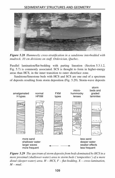
SEDIMENTARY STRUCTURES AND GEOMETRY
Figure 5.28 Hummocky cross-stratification in a sandstone interbedded withmudrock. 10 cm divisions on staff. Ordovician, Quebec.
Parallel lamination/flat-bedding with parting lineation (Section 5.3.1.2,Fig. 5.7) is commonly associated. SCS is thought to form in higher-energyareas than HCS, in the inner transition to outer shoreface zone.
Sandstone/limestone beds with HCS and SCS are one end of a spectrumof deposits resulting from storm deposition (Fig. 5.29). Storm-wave deposits
amalgamatedH types
micro-hummocky
lenses
stormbeds andgraded
laminitesnormalHFXM
FXMtypes
more sandshallower waterlarger wavesmore frequent
less sanddeeper waterweaker effectsless frequent
Figure 5.29 The spectrum of storm deposits from beds dominated by HCS in amore proximal (shallower-water) area to storm beds (‘tempestites’) of a moredistal (deeper-water) area. H – HCS, F – flat-bedding, X – cross-lamination,M – mud.
109

SEDIMENTARY STRUCTURES AND GEOMETRY
give way to storm-current deposits below storm wave-base, and these typi-cally consist of thin (0.01–0.5 m), sharp-based (with sole structures), gradedand cross-laminated beds interbedded with outer shelf mudrocks. Storm cur-rent beds are often referred to as ‘tempestites’. Some such beds are concen-trations of fossils (see Section 6.2.2).
5.3.3.10 Beach cross-stratificationSiliciclastic and carbonate sands deposited on a beach of moderate to highwave activity are characterised by a very low-angle planar cross-stratification,arranged into truncated sets (Fig. 5.30). The low-angle flat-bedding is typi-cally directed offshore, but shoreward-directed bedding may also be presentthrough sand deposition on the landward side of a beach berm. Bound-aries between sets represent seasonal changes in the beach profile. The beds,which may show reverse grading, are formed by wave swash–backwash andcommonly possess primary current lineation (Section 5.3.1.3, Fig. 5.7). Inaddition, shallow channel structures may be present, oriented normal to theshoreline and cutting the flat bedding at a low angle, which were produced byrip currents. Lenses of cross-laminated and/or cross-bedded sand may occurwithin the flat-bedded beach sand from the development of ripples (especiallywave-formed), ridges and berms in the foreshore environment.
The texture and composition of the sediment may help to confirm a beachorigin (Sections 4.2 and 3.2.1); beach sandstones are typically quartzitic aren-ites with well-sorted and rounded grains. Burrows and fossils may also be
Figure 5.30 Beach-foreshore bedding consisting of truncated sets oflow-angle, parallel-laminated sand (with parting lineation). Units ofcross-lamination may occur in beach facies, together with some bur-rows and heavy mineral concentrations. Field of view 2 m across.Pleistocene, Mallorca.
110

SEDIMENTARY STRUCTURES AND GEOMETRY
present, and heavy mineral layers, including placer beds of magnetite orilmenite grains (Section 3.7). There may be interbedded lenses and bedsof conglomerate, with well-sorted and rounded pebbles, which may showimbrication (Section 4.4) and could be bored (see Fig. 5.79).
Limestones deposited in a beach environment may contain keystonevugs (Section 5.4.1.2), millimetre-sized holes, mostly now filled with calcite,formed through the entrapment of air in the sand through rising andfalling tides.
5.3.3.11 Aeolian cross-beddingCompared with cross-bedding of subaqueous origin, cross-bedding producedby wind action generally forms sets which are much thicker, and the cross-beds themselves dip at higher angles (Fig. 5.31). Sets of aeolian cross-bedsare typically several metres (up to 30 m) in height. Cross-beds can be troughor planar in shape and they most commonly have tangential bases. Foresetscommonly dip up to angles in excess of 30◦. By way of contrast, cross-bedding formed subaqueously is generally less than 2 m in thickness andcross-bed dips are generally less than 25◦.
Within aeolian cross-bed sets, there are commonly major horizontal ero-sion surfaces cutting through the cross-beds (master bedding surfaces, seeFig. 5.16), which represent periods of deflation and changes in the positionof the watertable. The cross-beds themselves commonly show reverse grad-ing from avalanching (grain-flow deposits), and normal grading from traction
Figure 5.31 Aeolian cross-bedding characterised by set heights of severalmetres, and high angles of dip (more than 30◦). Height of exposure 20 m.Jurassic, Utah.
111

SEDIMENTARY STRUCTURES AND GEOMETRY
flow; these coarser layers may alternate with finer, thinner beds depositedfrom suspension (grain-fall deposits) (see Fig. 5.17). Aeolian sandstone suc-cessions typically consist solely of large-scale cross-bedded sets, althoughthere may be interbedded thin conglomerates and cross-bedded sandstones offluvial origin.
If an aeolian origin is suspected, then also look at the composition andtexture of the sediment (Sections 3.2.1 and 4.2). Aeolian sandstones typicallyconsist of well-sorted and well-rounded medium-sand quartz arenites. Thequartz grains may show frosting (a dull lustre) and mica is generally absent.They may also be red.
5.3.3.12 Lateral accretion surfaces / epsilon cross-beddingWithin cross-bedded channel sandstones there can sometimes be discerneda larger-scale low-angle bedding, oriented normal to medium/smaller-scalecross-stratification (Fig. 5.32). The surface cuts across the unit at a low angle(5–10◦) and becomes asymptotic towards the base of the channel sandstone.This epsilon cross-bedding forms through lateral migration of the channel andrepresents the successive growth and lateral accretion of point bars. Thesesurfaces are generally 1 m or more in height and continue laterally for severalmetres to more than 10 m. Lateral accretion surfaces are typical of mean-dering river channel sandstones but they can also occur in delta distributaryand tidal channel deposits.
5.3.3.13 Small-delta / fan-delta cross-beddingWhere small, simple deltas build into lakes and lagoons (these are oftenreferred to as ‘Gilbert-type’ deltas), very large-scale cross-bedding candevelop which represents the prograding front of the delta (delta slope). Thethickness of the cross-bedded unit (a few metres, exceptionally up to tens,but even hundreds of metres have been recorded) reflects the depth of waterinto which the delta was advancing. For a very high cross-bed set, the termclinoform can be used (Section 5.3.3.14).
Foresets dip at angles up to 25◦ and usually consist of sand, passingdown into much finer-grained and well-developed bottom sets of silt and clay,deposited largely from suspension in front of the delta. Top sets are also welldeveloped and can consist of lenticular gravels, sands and finer sediments,deposited by streams on the delta top, where they may be reworked by waves.
Small-delta cross-bedding is identified by the presence of well-developedtop sets and bottom sets (the former contrasting with cross-bedding formedfrom dunes and sand-waves) and the presence of one thick set. Thesesmall deltas occur as a wedge or fan in marginal-lacustrine or marginal-marine settings.
112

SEDIMENTARY STRUCTURES AND GEOMETRY
Fig
ure
5.32
Lat
eral
accr
etio
nsu
rfac
es(a
rrow
ed)
givi
nga
larg
e-sc
ale
(eps
ilon
)cr
oss-
stra
tific
atio
nw
ithi
na
smal
lch
anne
l,w
hich
infa
ctis
cutb
ya
larg
erch
anne
lto
the
left
.Pal
aeoc
urre
ntdi
rect
ion
tow
ards
obse
rver
,as
dedu
ced
from
smal
ler-
scal
ecr
oss-
bedd
ing
wit
hin
the
sand
ston
eun
its
and
the
orie
ntat
ion
ofth
ech
anne
l-fil
lit
self
.T
hecl
iff
is5
mhi
gh.
Car
boni
fero
us,
N.E
.E
ngla
nd.
113

SEDIMENTARY STRUCTURES AND GEOMETRY
Figure 5.33 Clinoforms: large-scale, gently dipping limestone beds which areofflapping from a carbonate platform and downlapping on to deeper watermudrocks. The cliff is 50 m high. Cretaceous, French Alps.
5.3.3.14 Very large-scale cross-strata and clinoformsIn some situations, high cliffs along coasts or in mountainous areas, verylarge-scale cross-strata can be observed (Fig. 5.33, also see Fig. 5.83). Ifthese are on a seismic scale (>50 m thick), then the term clinoforms can beused. These features are commonly developed at carbonate platform marginsand adjacent to reefs, where the dipping beds will be made of shallow-water material, fragments of reef-rock, bioclasts and ooids, for example. Theangle of dip with these debris beds varies from a few degrees to around30◦, depending largely on the grain-size of the sediment available (lowerangle for finer sediment). There may be quite large blocks within the dippingbeds or at their base. If accessible, look at the geometry of the clinoformbeds (planar, sigmoidal, oblique), the thickness, sediment grain-size and theinternal structure of the beds. Are there any patterns (cycles) in the bedthickness, such as thickening, thinning or bundling (see Section 8.4.3)?
5.3.3.15 Antidune cross-beddingThis is a rare but important structure since it indicates high flow velocities inthe upper flow regime. Antidunes are low-amplitude bedforms in sand-gradesediment which migrate upstream through deposition of sediment on theupstream-facing slope of the bedform. Antidunes can be observed on modernbeaches, in the backwash zone, and in rivers, recognised by standing wavesand breaking waves moving upstream against the flow. The cross-beddingformed by the migration of antidunes is directed upcurrent, so other evidenceof flow direction is required (e.g., flute marks on the base of the bed) to becertain that the supposed antidune cross-bedding is oriented against the flow.This type of cross-bedding generally has a lower angle of dip and is less welldefined than that formed by lower flow velocity subaqueous dunes. Antidunecross-bedding is known from turbidite and fluvial sandstones (but it is veryrare), and pyroclastic surge deposits (Fig. 3.26).
114

SEDIMENTARY STRUCTURES AND GEOMETRY
5.3.3.16 Cross-bedding in conglomeratesThis is usually present in single sets, with set heights in the range of 0.2 to2 m. Cross-beds, generally planar and low-angle, occur in tabular, wedge andlenticular-shaped units. Cross-bedding is common in conglomerates depositedin fluvial environments (braided streams and stream floods) where it formsfrom the downstream migration of bars at high stage.
5.3.4 Graded bedsThese beds show grain-size changes from bottom to top. The most commonis normal graded bedding where the coarsest particles at the base give way tofiner particles higher up (Figs 5.34 and 4.7). The upwards decrease in grain-size can be shown by all particles in the bed or by the coarsest particles only,with little change in the grain-size of the matrix. Composite or multiple-graded bedding is where there are several graded units within one bed.
Less commonly, reverse (or inverse) grading is developed, where thegrain-size increases upwards (see Fig. 5.34). This can occur throughout abed, or more commonly it occurs in the bottom few centimetres of the bed,with normal grading following. Reverse grading may affect only the coarseparticles. Graded bedding can be observed (and measured) in conglomer-ates with no difficulty (see Section 4.6) and in sandstones with the aid of ahand-lens.
Normal graded bedding usually results through deposition from waningflows; as a flow decelerates so the coarsest (heaviest) particles are depositedfirst and then the finer particles. Such graded bedding is typical of turbidity-current and storm-current deposits (e.g., Fig. 8.12). Composite graded bed-ding is usually the result of pulses in the current.
Reverse grading can arise from an increasing strength of flow during sed-imentation, but more commonly from grain dispersion and buoyancy effects.It commonly occurs in the deposits of high-concentration sediment–watermixtures. Laminae deposited on beaches by swash–backwash are commonlyreversely graded, as are cross-beds deposited by avalanching and grain flow
normal inverse ungraded
Figure 5.34 Different types of graded bedding.
115

SEDIMENTARY STRUCTURES AND GEOMETRY
(see Fig. 5.14). Reverse grading can occur in the lowest parts of sedimentgravity flow deposits such as grain-flow and debris-flow deposits.
5.3.5 Massive bedsMassive beds have no apparent internal structure. It is first necessary toascertain that this really is the case and that it is not simply due to surfaceweathering or a uniform grain-size. Blocks collected in the field and cut andpolished or etched in the laboratory may show that structures are indeedpresent (lamination, bioturbation, etc.). Other techniques which may bringstructures to light include staining the surface, as with methylene blue, whichhighlights the organic matter, or Alizarin red S + potassium ferricyanide,which picks out dolomite/calcite and iron-rich/iron-poor carbonate; covering
Figure 5.35 Massive bedding and cross-bedding in fluvial sandstone. Creta-ceous, Czech Republic.
116

SEDIMENTARY STRUCTURES AND GEOMETRY
the surface in a thin oil (very useful for chalks); or using X-radiography atthe local hospital (cut 0.5 cm-thick slabs of the rock and ask nicely!).
If the bed really is structureless then this is of interest and attempts shouldbe made to deduce why. The two alternatives are that it was deposited withoutany structure or that the depositional structure was subsequently obliteratedby such processes as bioturbation (Section 5.6.1), recrystallisation, dolomi-tisation and dewatering (Section 5.5). Where an original structure has beendestroyed, careful examination of the bed, or again of cut and stained blocks,may reveal evidence for this; wisps of lamination may remain, the sedimentmay appear churned and homogenised.
Truly massive beds deposited in this condition mostly arise through rapidsedimentation (‘dumping’), where there was insufficient time for bedformsto develop. Massive bedding is a feature of some turbidity-current and grain-flow sandstones, and debris-flow deposits, and occurs in some fluvial sand-stones; see Figs 5.35 and 4.7 for examples.
(a) (b)
Figure 5.36 Shrinkage cracks: (a)formed by desiccation, typicallycomplete polygons, can be straight-sided as shown, or less regular;(b) formed through syneresis, typi-cally incomplete with either bird’sfoot or spindle shape. In (a), thecracks are depicted as having suf-fered little subsequent compactionand so appear V-shaped in section;in (b) the crack fills are ptygmati-cally folded through compaction.
5.3.6 Shrinkage cracks (mudcracks) and polygonal structuresThese are present in many fine-grained sediments, especially mudrocks andlime mudstones, and most form through desiccation on exposure, causingshrinkage of the bed or lamina(e) and thus cracking. Many desiccationcracks define a polygonal patternon the bedding surface (Fig. 5.36),although they may also be seenon bed undersurfaces. Polygons varyenormously in size, from millimetres tometres across. Several orders of crackpattern may be present. Sediment clastscan be liberated by desiccation andlead to intraformational and edgewiseconglomerates.
Sediments also crack subaqueously.Syneresis cracks form through sedi-ment dewatering, often resulting fromsalinity changes or osmotic effects.Syneresis cracks are characterised byan incomplete polygonal pattern. Thecracks are often trilete or spindle-shaped (Figs 5.36 and 5.37) and can bemistaken for trace fossils or evaporitepseudomorphs (and vice versa).
Desiccation and syneresis cracksare usually filled with coarser sediment,
117

SEDIMENTARY STRUCTURES AND GEOMETRY
Figure 5.37 Syneresis cracks in muddy limestone. Late Precambrian,Montana.
seen in vertical section as wedges, although these can be later deformed andfolded through compaction. Desiccation cracks indicate subaerial exposureand so are common in sediments of marine and lacustrine shorelines,and river floodplains. Syneresis cracks occur mostly in shallow sublittorallacustrine deposits.
Possibly related to syneresis cracks are molar-tooth structures (theylook like their name!), compacted cracks filled with fine-grained calciteoccurring in lime mudstones and dolomites. They are common in Precambrianstrata although their origin is controversial. They may relate to seismicactivity.
Polygonal cracks may also develop in carbonate sediments throughearly cementation and expansion of the surface crust. Tepee structures arecommonly associated (Section 5.4.2).
5.3.7 RainspotsRainspots are small depressions with rims, formed through the impact ofrain on the soft exposed surface of fine-grained sediments (Fig. 5.38). Insome cases the spots are asymmetrical and you can tell which way thewind was blowing. They mostly occur in desert playa and lacustrine shore-line sediments.
118

SEDIMENTARY STRUCTURES AND GEOMETRY
Figure 5.38 Rainspots on surface of mudstone. Permian, South Africa.
5.4 Depositional Structures of Limestones (Including Dolomites)This section describes sedimentary structures which are more commonlyfound in limestones rather than siliciclastic sediments.
5.4.1 Cavity structuresMany limestones contain structures which were originally cavities but havesince been filled with sediment and/or carbonate cement, in many cases soonafter deposition. These include geopetal structures, fenestrae (including birds-eyes), stromatactis, sheet cracks, neptunian dykes, caves, potholes and vugs.
Figure 5.39 Geopetal structure with-in a gastropod shell, 4 cm across.Carboniferous, Wales.
5.4.1.1 Geopetal structuresThis term can be applied toany cavity, mostly but not onlyin limestones, filled with internalsediment and cement (normallysparry calcite). The cavity-fill isa useful way-up indicator (thewhite sparite at the top), and thesurface of the internal sedimentprovides a ‘spirit level’, showingthe position of the horizontal atthe time of deposition. Geopetalstructures commonly form beneathshells (‘umbrella’ structures) andwithin skeletal grains (Figs 5.39and 5.40).
Careful measurement of geopet-al structures can show that a seriesof limestones had an original depo-sitional dip (Fig. 5.40). This is usually the case with fore-reef limestones andthe flank beds to mud mounds and patch reefs (as in Fig. 5.83).
119

SEDIMENTARY STRUCTURES AND GEOMETRY
back-reef
internalsediment
calcitecement
reef
fore-reef
Figure 5.40 Sketch of geopetal structures in back-reef facies, where sedimentwas deposited on a horizontal surface, and in fore-reef facies, where sedimentwas deposited on a slope. Geopetal structures can be used to show the originalangle of dip of the slope sediments.
5.4.1.2 Fenestrae (including birdseyes)These are cavity structures, usually filled with sparite, occurring in micritic,commonly peloidal limestones and dolomites. There are three common typesof fenestra: equant to irregular fenestrae (birdseyes), laminoid fenestrae andtubular fenestrae.
Birdseyes are typically a few millimetres across, equant in shape andformed through gas entrapment and desiccation in tidal-flat carbonatesediments (Fig. 5.41).
Laminoid fenestrae are elongate cavity structures, thin sheet cracks ineffect, parallel to the stratification. They usually occur between microbiallaminae, and result from desiccation and parting of the layers in a microbialmat. They are typically a few millimetres in height and several centimetresin length.
Tubular fenestrae are generally oriented normal to the bedding and area few millimetres across and several centimetres long. They may branchdownwards. These structures are mostly burrows or rootlets. Some may befilled with sediment rather than cement (sparite).
Keystone vugs are similar to irregular fenestrae (birdseyes) in shape(equant) and size (a few millimetres across) but occur in more grainy rocks(bioclastic and oolitic grainstones). These are typical of beach sediments andform by the trapping of air in the sand.
5.4.1.3 StromatactisThis is a specific type of cavity which is characterised by a smooth floorof internal sediment, an irregular roof and a cement filling, usually isopac-hous (equal thickness) fibrous calcite (grey) followed by drusy sparry calcite
120

SEDIMENTARY STRUCTURES AND GEOMETRY
Figure 5.41 Birdseyes (fenestrae) filled with sparite (dark) within peloidallimestone. Millimetre scale. Carboniferous, Wales.
(white) (Fig. 5.42). Stromatactis is common in mud-mound limestones (mas-sive lime mudstones/biomicrites, mostly of Palaeozoic age), but its originis unclear. Possible explanations include sediment dewatering, local seafloorcementation and scouring of sediment, and dissolution of sponges.
5.4.1.4 Sheet cracks and neptunian dykesThese are generally continuous cavities, either parallel to or cutting the bed-ding. Both can vary considerably in size, particularly the neptunian dykeswhich can penetrate down many metres. They have usually formed by crack-ing of the lithified or partially lithified sediment and opening up of cavities.They can be filled either with sediment of similar age and lithology to the hostsediment, or with quite different and much younger material. Sheet cracksand neptunian dykes can form in several ways, but penecontemporaneous tec-tonic movements, early compaction and settling, or slight lateral movementcan all cause cracking and fissuring of the limestone mass.
5.4.1.5 Karstic cavities and karstic brecciasSomewhat similar structures to neptunian dykes, but often on a larger scale,can develop within a limestone mass when brought into contact with meteoric
121

SEDIMENTARY STRUCTURES AND GEOMETRY
Figure 5.42 Stromatactis cavities (flat floor of internal sediment, irregularroof, fibrous and drusy calcite fill) within lime mudstone. Field of view 10 cmacross. Devonian, Belgium.
water through uplift or a major sea-level fall. Dissolution (karstification)of the limestone can result in cave systems being formed which will varyfrom narrow vertical/subvertical channels (potholes) through to large caverns.These cavities usually cut across the bedding, although they may locallyfollow the stratification, and the walls are smooth to undulating, rather thanplanar. Flowstone (layers of fibrous calcite) may coat the walls of thesekarstic cavities and speleothems (stalactites/stalagmites) may also be present.Extensive cave systems develop close to the groundwater table (which maybe perched) and in the capillary zone above.
In most cases palaeokarstic cavities are subsequently filled with sediment,and this can range from non-marine red and green marls, sandstones and con-glomerates (which may contain vertebrate fossils), deposited by subterraneanstreams and percolating in from the land surface above, through to marinesediments washed in during a subsequent transgression.
A variety of distinctive breccias are associated with palaeokarsts andoccur upon palaeokarstic surfaces (see Section 5.4.2). They form from thefracturing of limestone and collapse of caves and so consist of angular clasts
122

SEDIMENTARY STRUCTURES AND GEOMETRY
of the host limestone with textures varying from fitted fabrics showing littledisplacement of clasts (crackle breccia) to a more clast-supported brecciawhere some movement has taken place (collapse breccias).
5.4.2 Palaeokarstic surfacesPalaeokarstic surfaces are formed through subaerial exposure and meteoricdissolution (karstification) of a limestone surface, generally under a humid cli-mate. They usually have an irregular topography, possibly with potholes andcracks descending down several metres (see Section 5.4.1.5), which devel-oped beneath a soil cover. Upon the surface there may still be a soil (nowa palaeosoil – red/grey mudrock with or without rootlets) or this may havebeen removed during a subsequent marine transgression so that marine faciesrest directly on the exposure surface. Volcanic ash may occur on the sur-face (see Section 3.11). Breccias of the host rock may also occur upon thekarstic surface.
The top surfaces of limestone beds should be examined carefullyfor evidence of karstification. Metre-scale shallowing-upward limestonecycles are commonly capped by palaeokarstic surfaces, indicating subaerialexposure. However, remember that limestone bedding planes commonlyshow the effects of pressure dissolution which can produce sharp, undulatingthrough to irregular, pitted and sutured surfaces, not unlike palaeokarsts (seeSection 5.5.7).
Associated with some palaeokarstic surfaces are laminated crusts. Thesewould normally occur on the top of the limestone bed, although they maybe cut by the dissolution surface. They typically consist of pale-brown, greyor reddened micritic limestone with a poorly defined lamination; small tubesmay be present which were the sites of rootlets. These crusts are pedogenicin origin and may be calcified root-mats or inorganic/microbial precipitates.In addition, there may be other indicators of soil processes: calcrete nodules,black pebbles, pisoids/vadoids and rhizocretions (Section 5.5.6.2).
Palaeokarstic surfaces are important since they indicate subaerial expo-sure. The degree of their development depends on the climate and the durationof the emergence.
5.4.3 HardgroundsThese structures are present in limestones where there has been synsedimen-tary cementation so that the sediment was partly or wholly lithified (hard) onthe seafloor. The top surface of a hardground usually provides the best evi-dence for a cemented seafloor. A hardground surface is usually encrusted bysessile organisms such as oysters, serpulid worms and crinoids, and penetratedby borings of such organisms as annelids, lithophagid bivalves and sponges(Figs 5.43 and 5.44; also see Figs 5.79 and 6.8 and Section 5.6.2). Beneath
123

SEDIMENTARY STRUCTURES AND GEOMETRY
encrustingfossils, e.g.oysters, crinoids
burrows
moreFe-rich
well-cemented
less well-cemented
borings, e.g.bivalves, sponges,annelids
Figure 5.43 Features of a hardground, generally indicating a pause in sedi-mentation and seafloor cementation.
Figure 5.44 View of hardground surface showing encrusting oysters andborings (circular holes). Millimetre scale. Jurassic, W. England.
124

SEDIMENTARY STRUCTURES AND GEOMETRY
hardground surfaces there may be horizontal cavities, formed from currentsscouring beneath the cemented seafloor, where fossils may be present, as wellas cements.
Many hardground surfaces themselves are planar, having been subjectedto corrasion (erosion through sand being moved across the surface), so thatborings and fossils in the sediment may be truncated. Other hardgrounds,generally in deeper-water limestones and chalks, have a more irregular surfacewith some relief where a degree of seafloor dissolution has taken place.Hardgrounds commonly have a nodular appearance, and this may be relatedto burrows and bioturbation which formed before the sediment was lithified.Hardgrounds may be impregnated with iron minerals and/or phosphate andthere may be iron oxide or phosphatic crusts on the hardground surface.Grains of glauconite may be present too. Hardgrounds can commonly betraced for many tens (even hundreds) of metres.
Beds partially lithified on the seafloor are referred to as firmgrounds (seeSection 5.6.3, Table 5.11).
Hardgrounds are not very common but they do give important environ-mental and diagenetic information. They generally form during times ofreduced or negligible sedimentation and they may coincide with periods ofrelative sea-level rise.
5.4.4 Tepee structuresAs a result of synsedimentary cementation of carbonate sediments, thecemented surface layer can expand and crack into a polygonal pattern.Intraclasts can also be generated. The cemented crust can be pushed andbuckled up to form tepees (pseudo-anticlines, Fig. 5.45), and where crackedthe crust can even be thrust over itself. Cavities can develop beneath thecemented surface layer and be filled with sediment and further cement. Tepeestructures can develop in shallow subtidal sediments, in conjunction withhardgrounds, but more commonly they are found in tidal-flat carbonates. Inthe latter case, microbial laminites, desiccation cracks, pisoids (vadoids) anddripstone cements are usually associated. Thus, most tepees indicate subaerialexposure and marine diagenesis, and with prolonged exposure complex mega-tepee horizons can form.
5.4.5 Stromatolites and microbial laminitesThese are biogenic laminated structures which have a great variety of growthforms. They develop through the trapping and binding of carbonate particlesby a surficial microbial mat (‘algal mat’) composed mainly of cyanobacteria(formerly called blue-green algae) and other microbes, and the biochemicalprecipitation of carbonate. Stromatolites are very common in Precambrian
125

SEDIMENTARY STRUCTURES AND GEOMETRY
Figure 5.45 Tepee structure in laminated limestone. Field of view 0.5 m.Triassic, Wales.
carbonate successions but they also occur in many Phanerozoic limestones,particularly those of peritidal origin.
Stromatolites vary from planar-laminated forms, also called microbiallaminites (Fig. 5.46), to domes (like cabbages) and columns (Fig. 5.47). Lam-inae are generally several millimetres in thickness and consist of micrite,peloids and fine skeletal debris.
With planar stromatolites, the microbial origin of the laminae is shown bysmall corrugations and undulations and preferential thickening over small sur-face irregularities. The laminae are commonly broken and disrupted throughdesiccation, and they may show regrowth and encapsulations upon fragmentsof the microbial mat. Tepee structures may be present, and intraclasts are com-monly generated from desiccation and exposure. Elongate cavities (laminoidfenestrae, Section 5.4.1.2) are common in microbial laminites and there maybe thin grainstone beds (possibly of storm origin) intercalated. Microbiallaminites are typical of tidal-flat limestones and dolomites and so may beassociated with fenestral lime mudstones and evaporites or their pseudo-morphs (see Section 3.6).
Domal stromatolites generally have laminae continuous from one dometo another, and they can be several tens of centimetres in diameter. Columnarstromatolites are discrete structures, usually forming in higher-energy loca-tions, so that intraclasts and grains commonly occur between the columns.
A useful notation for describing stromatolites in the field is given inFig. 5.48. The morphology of stromatolites commonly changes upwards, asa response to environmental changes, and large stromatolite structures mayconsist of lower orders of domes and columns. This notation provides a con-venient shorthand for describing such changes and variations. Stromatolites
126

SEDIMENTARY STRUCTURES AND GEOMETRY
Figure 5.46 Microbial laminites. Millimetre scale. Late Precambrian,Arctic Norway.
may form thin beds or may constitute complex reef-type structures. In Pre-cambrian rocks, stromatolites are very diverse in shape and microstructureand many have been given form genus and species names, like trace fossils.
Oncoids (also oncolites) are spherical to subspherical, unattached micro-bial structures, commonly with a crude concentric lamination (Fig. 5.49). Thelaminae may be asymmetric and discontinuous from growth on the top of theball while it was stationary. These microbial structures can be mistaken forpisoids (also called vadoids) of pedogenic origin (see Section 5.5.6.2). Oftenlooking similar to oncoids are rhodoliths, algal balls formed by calcifiedalgae, which are mostly red (coralline) algae.
5.5 Post-Depositional Sedimentary StructuresA variety of structures are formed after deposition, some through massmovement of sediment (slumping and sliding) and others through internalreorganisation by dewatering and loading. Post-depositional physico-chemicaland chemical processes produce stylolites, dissolution seams and nodules.
127

SEDIMENTARY STRUCTURES AND GEOMETRY
Figure 5.47 Columnar stromatolites developing from domed and planarforms. Height of column 15 cm. Late Precambrian, Arctic Norway.
laterally-linkedhemispheroids (LLH)
vertically-stackedhemispheroids(SH)
microbial laminites,irregular, crinklylaminae, desiccated,with fenestrae
oncoids:symmetric orasymmetricgrowth
Figure 5.48 Four common microbial (stromatolitic) structures: domal,columnar and planar stromatolites, and oncolites.
128

SEDIMENTARY STRUCTURES AND GEOMETRY
Figure 5.49 Oncoids – microbial laminae growing asymmetrically around apebble and shell. Tertiary, S.E. France.
5.5.1 Slumps and slides and megabrecciasOnce deposited, either upon or close to a slope, a mass of sediment canbe transported downslope. Where there is little internal deformation of thesediment mass, more often the case with limestones, then the transportedmass is referred to as a slide. Brecciation of the sediment mass can takeplace to produce large and small blocks.
Megabreccia is a term used for a deposit of large blocks. Some megabrec-cias are the result of fault activity during deposition and the erosion of faultscarps; others, notably those composed of limestone blocks and occurring intoe-of-slope locations, were commonly deposited during times of relative sea-level fall and collapse of a carbonate platform margin. Examine the blocks ina megabreccia and see if there is any evidence for subaerial exposure of thesediments before their deposition into deeper water (e.g., look for dissolu-tional cavities filled with red soil, ‘terra rossa’). See if the blocks have beenbored or encrusted by sessile organisms (oysters, serpulids, etc.) or iron oxideor phosphorite (particularly on their upper surface), while in the deeper-waterenvironment.
Where a sediment mass is internally deformed during downslope move-ment, then the term slump is more appropriate. A slumped mass typicallyshows folding; recumbent folds, asymmetric anticlines and synclines, andthrust folds are common, on all scales (Figs 5.50 and 5.51). Fold axes areoriented parallel to the strike of the slope, and the direction of overturning
129

SEDIMENTARY STRUCTURES AND GEOMETRY
Figure 5.50 Slump-folded, deeper-water nodular limestones. Disharmonicnature of folding shows that the deformation is synsedimentary. Height ofcliff 4 m. Devonian, Germany.
erosion ofslump fold
axis of slump foldoverturned downslope
undisturbedbeds
undisturbedbeds
scour thrust slump fold slip planelocal intraformationalbreccia
direction of movement
Figure 5.51 Principal features of a slumped bed. Slumps can occur on a scaleof centimetres to kilometres.
of folds is downslope. It is thus worth measuring the orientation of fold axesand axial planes of slump folds to ascertain the direction of slumping and sothe palaeoslope. Slumps and slides range from metres to kilometres in size.Many are triggered by earthquake shocks.
The presence of a slump or slide in a succession can be deduced fromthe occurrence of undisturbed beds above and below, and a lower contact
130

SEDIMENTARY STRUCTURES AND GEOMETRY
(the surface upon which the slump or slide took place), which cuts across thebedding (Fig. 5.51). Be sure that lateral mass movement of sediment tookplace, since somewhat similar convolutions and brecciations of strata can beproduced by dewatering (see below) and other processes.
5.5.2 Deformed beddingDeformed bedding, and terms such as disrupted, disturbed, convolute and con-torted bedding, can be applied where the bedding, cross-bedding and cross-lamination produced during sedimentation have been subsequently deformed,but where there has been no large-scale lateral movement of the sediment(see Figs 5.15 and 5.52).
Convolute bedding typically occurs in cross-laminated sediments, with thelamination deformed into rolls, small anticlines and sharp synclines. Suchconvolutions are commonly asymmetric and overturned in the palaeocur-rent direction. Contorted, disturbed and disrupted bedding applies to lessregular deformations within a bed, involving irregular folding, contortions,disruptions and injections without any preferred orientation or arrangement.
Figure 5.52 Disturbed and distorted laminae with flame structures fromrapid deposition and dewatering. Millimetre scale. Fine tuff, Ordovician,N.W. England.
131

SEDIMENTARY STRUCTURES AND GEOMETRY
Wholesale or local brecciation of some beds can occur. Overturned cross-bedding affects the uppermost part of cross-beds and the overturning isinvariably in the downcurrent direction (see Fig. 5.18).
Deformed bedding can arise from a number of processes. Shearing by cur-rents on a sediment surface and frictional drag exerted by moving sand arethought to cause some convolute bedding and overturned bedding. Dewa-tering processes such as fluidisation and liquefaction are often induced byearthquake shocks, in many cases associated with synsedimentary movementson faults.
5.5.3 Sandstone dykes and sand volcanoesThese are relatively rare structures but readily identifiable, the dykes fromtheir cross-cutting relationship with bedding and fills of sand, and the sandvolcanoes (formed where sand moving up a dyke reached the sediment sur-face) from their conical shape with a central depression, occurring on abedding plane.
Dewatering and the upward escape of water, usually initiated by earth-quake shocks, is the cause of these structures.
5.5.4 Dish structures and dish-and-pillar structuresThese consist of concave-up laminae (the dishes, Fig. 5.53), generally a fewcentimetres across, which may be separated by structureless zones (the pil-lars). Dish structures and dish-and-pillar structures are formed by the lateraland upward passage of water through a sediment. Although not restrictedto sandstones of a particular environment or depositional mechanism, theyare common structures of sediment gravity-flow deposits which occur indeepwater slope, fan and apron successions.
Figure 5.53 Dish structures in sandstone. Upper Carboniferous, N.E.England.
132

SEDIMENTARY STRUCTURES AND GEOMETRY
Figure 5.54 Load structures on underside of sandstone bed. Field of view1 m. Late Precambrian, Norway.
(a)
(b)
Figure 5.55 (a) Scoured surfaceat base of sand bed; trunca-tion of mud laminae at con-tact. (b) Loaded surface, throughsinking of sand into mud. Upwardinjection of mud (flame structure)and depression and contortion ofmud laminae. A scoured surfacecan be deformed by loading.
5.5.5 Load structuresLoad structures are formed through dif-ferential sinking of one bed into another.Load casts are common on the solesof sandstone beds overlying mudrock,occurring as bulbous, rounded structures,generally without any preferred elonga-tion or orientation (Fig. 5.54). Mud canbe injected up into the sand to form flamestructures (Figs 5.52 and 5.55). Also as aresult of loading, a bed, usually of sand,can sink into an underlying mud andbreak up into discrete masses, formingthe so-called ball-and-pillow structure.On a smaller scale, individual ripplescan sink into underlying mud, producingsunken ripples or sandstone balls.
Close attention should be paid tosandstone–mudrock junctions, since itwill often be found that gravity-loadinghas taken place (Figs 5.55 and 5.5).
133

SEDIMENTARY STRUCTURES AND GEOMETRY
5.5.6 NodulesNodules (also called concretions) commonly form in sediments after depo-sition (Fig. 5.56); effectively most nodules are local patches of cementation.Two broad types are diagenetic nodules formed during burial (shallow ordeep) and pedogenic nodules formed by soil processes.
5.5.6.1 Diagenetic nodulesMinerals commonly comprising nodules formed during diagenesis are fine-grained varieties of calcite, dolomite, siderite, pyrite, collophane (calciumphosphate), quartz (chert/flint) and gypsum-anhydrite. Calcite, gypsum-anhydrite, pyrite and siderite nodules a few millimetres to a few tens ofcentimetres in diameter are common in mudrocks; chert nodules are morecommon in limestones, and calcite and dolomite nodules, in some cases ofimmense size (metres across), occur in sandstones. The latter are sometimescalled doggers (Fig. 5.57).
Nodules may be randomly dispersed or concentrated along particular hori-zons. Nodule shape can vary considerably from spherical to flattened, toelongate, to highly irregular. Some nodules nucleated around fossils and oth-ers formed within animal burrow systems; however, the majority are notrelated to any obvious pre-existing inhomogeneity in the sediment. Somenodules possess radial and concentric cracks, filled with crystals usually ofcalcite, or siderite or sediment (Fig. 5.58). The cracks in these septariannodules form through contraction (dewatering) of the nodules soon aftertheir formation.
Figure 5.56 Diagenetic calcareous nodules with a regular spacing inhemipelagic mudrock. Devonian, Germany.
134
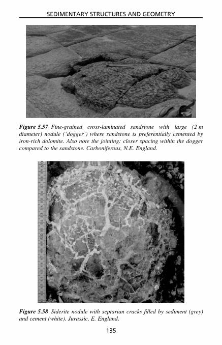
SEDIMENTARY STRUCTURES AND GEOMETRY
Figure 5.57 Fine-grained cross-laminated sandstone with large (2 mdiameter) nodule (‘dogger’) where sandstone is preferentially cemented byiron-rich dolomite. Also note the jointing: closer spacing within the doggercompared to the sandstone. Carboniferous, N.E. England.
Figure 5.58 Siderite nodule with septarian cracks filled by sediment (grey)and cement (white). Jurassic, E. England.
135

SEDIMENTARY STRUCTURES AND GEOMETRY
Geodes are a type of nodule with hollow centres which usually havecrystals growing in towards the middle. Some geodes have formed throughthe dissolution of evaporite nodules (especially gypsum-anhydrite), and theyare usually composed of quartz, calcite or dolomite. These often have acauliflower-like appearance on the outside (see Fig. 3.19).
A further particular type of nodule is one composed of calcite that exhibitsa cone-in-cone structure (Fig. 5.59). The calcite consists of fibrous crystalsseveral to 10 or more centimetres in length which are arranged in a fan-ning, conical pattern, oriented at right angles to the bedding. Cone-in-conestructure generally develops in organic-rich mudrocks during burial, and thecurious crystal form may relate to calcite crystal growth under high pore-fluidpressure during compaction.
Nodules can form at various times during diagenesis and burial; however,the majority of nodules in muddy sediments form during early diagenesis,before the main phase of compaction. Calcareous nodules are common inmarine mudrocks generally, but they do form in soils as calcretes (see below),so are found in floodplain and lacustrine mudrocks. Pyritic nodules aremore common in organic-rich muddy marine sediments (since seawater hasan abundant supply of sulphate which is reduced to sulphide by bacteria),whereas siderite is more common in organic-rich non-marine sediments.
Figure 5.59 Cone-in-cone structure: vertically oriented conical fibrous cal-cite crystals. Millimetre scale. Carboniferous, N.E. England.
136

SEDIMENTARY STRUCTURES AND GEOMETRY
crushed fossilsin mudrock
post-compactionalnodule
pre-compactionalnodule
full-bodied fossilsin nodule
ba
Figure 5.60 Pre-compactional(early diagenetic) and post-com-pactional (late diagenetic) nod-ules in mudrocks. An estimate ofthe amount of compaction canbe obtained from early diageneticnodules as [(a − b)/a] × 100%.
As a result of the usual earlydiagenetic origin, lamination in hostmuddy sediment is deflected around thenodules (Fig. 5.60), and the nodulescan preserve the original laminathickness. The amount of compactionthat has taken place can be deducedfrom these nodules (Fig. 5.60). Fossilsand burrows in early diagenetic nodulesare protected from compaction andso are unbroken and uncompressed,contrasting with compacted fossils inadjacent mudrocks.
Early diagenetic nodules formingclose to the sediment–water interfacecan be exposed on the seafloor as aresult of a storm, and then reworked, and perhaps encrusted and boredby organisms (the nodules act as local hardgrounds: Section 5.4.3). Chertnodules in limestones (including flint nodules in chalk) and carbonate nodulesin sandstones are also chiefly of early diagenetic origin. Late diageneticnodules in muddy sediments formed after compaction are relatively rare;in these the lamination is undeflected from the host sediment through thenodules (Fig. 5.60).
A scheme for describing nodules is given in Table 5.4.
5.5.6.2 Calcretes (caliches): pedogenic nodules and limestonesCalcareous nodules and layers (calcrete or caliche) develop within soils ofsemi-arid environments where evaporation exceeds precipitation. In the geo-logical record they are typically found in red-bed successions, especially in
Table 5.4 Nodules: what to look for.
1. Determine composition of nodules and nature of host sediment.2. Measure nodule size and spacing.3. Describe shape and texture; are nodules forming within burrows?4. Look for a nucleus (such as a fossil).5. Try to determine when formed:
(a) early diagenetic: contain full-bodied fossils, locally reworked;pre-compaction so host–sediment lamination is deflected; or
(b) late diagenetic: contain crushed fossils; post-compaction so donot affect host–sediment lamination.
6. Check if calcrete (pedogenic nodules) (Section 5.5.6.2).
137

SEDIMENTARY STRUCTURES AND GEOMETRY
floodplain mudrocks, but they can also occur in marine clastic sediments,formed when the latter become emergent.
In the field, calcretes usually occur as pale-coloured nodules of fine-grained calcite, or rarely dolomite (dolocrete), a few to many centimetresin diameter, generally with a downward elongation (Fig. 5.61), best devel-oped in red mudrocks. They vary from randomly scattered to closely packednodules, and may form a dense limestone bed as the calcrete develops andmatures (Fig. 5.62). Some calcrete nodules have nucleated and grown aroundplant roots; rhizocretion is a general term for such precipitates. These com-monly taper downwards and may branch (Fig. 5.63). Veins filled with calciteare also common in calcretes, as well as open fractures and cracks.
Another form of pedogenic limestone is a laminar calcrete or laminatedcrust (Section 5.4.2), where the laminae are usually slightly irregular inthickness and result from subtle variations in crystal size and colour. Somelaminated calcretes are calcified root mats and so contain small tubules. Thesecrusts develop upon nodular calcretes when the soil zone is fully cemented(plugged), and on limestone surfaces. In many calcretes there are peloids
Figure 5.61 Calcrete (calcareous palaeosoil) consisting of elongate nodulesof fine-grained calcite. Devonian, W. England.
138

SEDIMENTARY STRUCTURES AND GEOMETRY
A
B
C
Figure 5.62 Calcrete profiles: incipient nodules, mature nodules and pluggednodular profile with laminated calcrete.
Figure 5.63 Rhizocretions: calcified plant roots. Here the soil has beenwashed out to reveal the rhizocretions. Field of view 1 m across.Pleistocene, Mexico.
139

SEDIMENTARY STRUCTURES AND GEOMETRY
and pisoids (vadoids) present; these spherical grains are commonly irregu-larly laminated and are probably formed by bacterial processes. They can beseveral centimetres in diameter.
Where calcretes have developed within coarser sediments, pebbles andgrains may be split apart. In older, more mature calcretes, veins of calcitemay cross-cut a dense lithified calcrete and wholesale brecciation can alsooccur, resulting in intraclasts and tepee structures (see Section 5.4.4). Cavitiesmay be produced and filled with sediment, pisoids and cement.
Black pebbles are present in some calcretes, and can be reworked intobasal lags. They are possibly the result of natural fires burning vegetationand blackening the soil.
Calcretes are a useful palaeoclimatic indicator, but they also reflect lengthyperiods of non-deposition (hundreds to thousands of years or more) duringwhich the pedogenic processes operated.
5.5.7 Pressure dissolution and compactionAs a result of overburden and tectonic pressure, dissolution takes place withinsedimentary rock masses along certain planes to produce a variety of smoothto irregular surfaces (Fig. 5.64). Pressure dissolution effects are commonlyseen at the junctions of limestone beds and within limestones. This processprobably begins quite early during burial, but is well developed after burialbelow many hundreds of metres. There are two major styles of pressuredissolution, leading to sutured and non-sutured seams. Pressure dissolutioncan result in a pseudobedding (Fig. 5.65).
The sutured type are the well-known stylolites, which are generally bedding-parallel, although they can be at high angles to the bedding too. Insoluble
stylolite swarm
fossil/clastloss at stylolite
stylolitesbetween clasts
stylolite stylobreccia
pressuredissolution seam
Figure 5.64 Different products of pressure dissolution.
140

SEDIMENTARY STRUCTURES AND GEOMETRY
pseudobedding frompressure dissolution
true beddingno dissolution
bedding + dissolution
lithology grain size
Figure 5.65 Bedding, pseudobedding and pressure dissolution planes.
Figure 5.66 Stylolites in micritic limestone (chalk). Field of view 20 cmacross. Cretaceous, E. England.
material (chiefly clay) is concentrated along the seams (Fig. 5.66). Stylo-lites occur as single sutured planes or as zones, or swarms; high (severalcentimetres) and low amplitude forms can be distinguished.
Non-sutured dissolution seams with little relief are also common, perhapsmore so in argillaceous limestones. They are undulating, branching and anas-tomosing, and also occur singly or in seams. They can pass into cleavageplanes in adjacent mudrocks. Nodular, lumpy and pinch-and-swell texturescan be developed on the centimetre or decimetre scale.
141

SEDIMENTARY STRUCTURES AND GEOMETRY
Extreme pressure dissolution can give a limestone a brecciated appearance(stylobreccia) with a fitted fabric to the ‘pebbles’. The term flaser limestonehas been used for this rock type. The occurrence of pressure dissolution canbe demonstrated by the partial loss of fossils at or across stylolites. In somecases sutured contacts occur between fossils or pebbles in a limestone.
Stylolites also occur in sandstones, but they are not so common. They canoccur between pebbles in conglomerates, leading to a pitting of the pebbles.
Compaction of muddy sediments begins soon after deposition and themain effects are the crushing of fossils and reduction in the thickness ofdeposited sediment by a factor of up to 10 (best seen where there are earlydiagenetic nodules in the mudrock; Section 5.5.6). Compaction coupled withpressure dissolution also enhances limestone–mudrock contacts.
5.5.8 Veins, beef and discontinuities (joints and fractures)Although many veins are of purely tectonic origin and are mineralised throughthe passage of hydrothermal fluids, veins can form through compaction andburial diagenetic processes. The most common sedimentary veins are thosecomposed of fibrous gypsum (satin spar), most of which occur in mudrocksand form through the hydration of anhydrite during uplift of evaporitic strata.Cross-cutting veins of calcite occur in some mature calcretes, karstified lime-stones, hardgrounds and tepeed and fractured supratidal carbonates, althoughin many cases these would be more appropriately called fractures and themineral infills are cements.
Sheets of calcite parallel to bedding occur within some mudrocks, usuallythose rich in organic matter, and they generally consist of vertically orientedfibrous crystals. These calcite sheets are known locally as ‘beef ’ (!), and arerelated to cone-in-cone structure (see Section 5.5.6.1).
Joints and fractures in sedimentary rocks have formed mostly throughtectonic stresses but in some cases they are related to depositional or burialprocesses: the cooling joints in some volcaniclastic deposits (Section 3.11),joints in glacial diamictites from ice loading, the cleat in coal (Section 3.10),and fractures in competent beds (such as well-cemented limestones andcherts) simply related to overburden pressure. There may be several setsof these discontinuities, and they may be of several generations too, cross-cutting and offsetting each other. The spacing of joints relates to the thickness,competence and brittleness of the rock, with a closer spacing in more brittlerocks (see Fig. 5.57 for an example). For the features to note with regard tojoints and fractures see Table 5.5 and for the terms for spacing see Table 5.6.
5.5.9 DendritesDendrites are strange patterns, usually on bedding planes, resulting from theprecipitation of manganese and iron oxides/hydroxides (Fig. 5.67). They are
142

SEDIMENTARY STRUCTURES AND GEOMETRY
Table 5.5 Features to note with fractures.
1. Measure the orientation of the fractures, and their angle if they are notvertical; the fractures may indicate the regional stress field. Comparewith fault and fold trends.
2. Measure the spacing of fractures; are they closely or widely spaced(Table 5.6)? See whether there is a correlation of spacing to bed thick-ness.
3. How laterally persistent are the fractures? Are they arranged en-echelon?
4. Do the fractures generate rock clasts? Are they blocky (equidimen-sional) or tabular (thickness much less than length or width) or colum-nar (height much greater than cross-section)?
5. Are the fractures filled by cement or sediment? Are they open or not?Are their walls smooth, rough, polished or slickensided? There maybe alteration of the wall-rock adjacent to fractures from the passageof porefluids, as in local dolomitisation of a limestone, or in loss ofcolour in clastic red beds.
Table 5.6 Spacing of discontinuities (fractures and joints) insediments and sedimentary rocks.
Term Spacing
very widely spaced greater than 2 mwidely spaced 600 mm to 2 mmedium spaced 200 mm to 600 mmclosely spaced 60 mm to 200 mmvery closely spaced 20 mm to 60 mmextremely closely spaced less than 20 mm
generally black and look like fossil leaves. They are really something of acuriosity, with little sedimentological or diagenetic interest.
5.6 Biogenic Sedimentary StructuresMany structures are formed in sediments through the activities of animals andplants, in addition to the microbial laminites and stromatolites described inSection 5.4.5. Structures produced vary considerably from poorly defined andvague disruptions of lamination and bedding, to discrete and well-organisedtrace fossils (ichnofossils) which can be given a specific name. The textureproduced by this biogenic activity is the sediment’s ichnofabric. Trace fossilscan often be interpreted in terms of the animal’s activity which gave rise to
143

SEDIMENTARY STRUCTURES AND GEOMETRY
Figure 5.67 Dendrites – patterns looking like leaves but produced by man-ganese and iron oxide precipitation on a bedding plane. Jurassic, Germany.
the structure, but the nature of the animal itself can be difficult or impossibleto deduce since different organisms may have had a similar mode of life.Also, one animal can produce different structures depending on its behaviourand on the sediment characteristics (grain-size, water content, etc.).
Burrow structures are commonly made by crustaceans, annelids, bivalvesand echinoids, and surface trails and tracks by crustaceans, trilobites, annelids,gastropods and vertebrates. Structures somewhat similar to burrows can beproduced by the roots of plants, although the latter may contain carbonisedcores (Section 5.6.4).
Care should be taken not to mistake modern organic markings, such aspolychaete and sponge borings and limpet and periwinkle tracks, frequentlyseen on rocks in the intertidal zone, for trace fossils. Small holes and dis-colorations made by lichens on limestone can also look like ancient biogenicstructures. Confusion can also arise with some sedimentary structures, suchas syneresis cracks, tool marks, dewatering structures and diagenetic nodules,and spots and lineations in low-grade metamorphosed slates.
Some biogenic sedimentary structures on bedding planes are best seen ina directed low-angle light. Some major discoveries have been made at dawn
144

SEDIMENTARY STRUCTURES AND GEOMETRY
(or dusk) when the sun is low in the sky. To save getting up early, examinethe surfaces of loose slabs at different angles; it may be possible to see thestructures better this way.
A scheme for the examination of trace fossils is given in Table 5.7.
5.6.1 Bioturbation and IchnofabricBioturbation refers to the disruption of sediment by the activity of organismsand plants. The ichnofabric generated varies from scattered discrete burrowstructures (commonly filled with sediment of a different colour, composi-tion or grain-size) to completely disrupted sediment which has a churned
Table 5.7 Trace fossils: how to describe them and what to look for.
1. Sketch (or photograph) the structures; measure size, width and diam-eter; determine the bioturbation index (Table 5.8). Note the faciescontext.
2. Trails and tracks (on bedding surfaces or undersurfaces)(a) Examine trail pattern: note whether regular or irregular pattern,
whether trail is straight, sinuous, curved, coiled, meandering orradial.
(b) Examine trail itself: if a continuous ridge or furrow, notewhether central division and any ornamentation (such as chevronpattern); with appendage marks or footprints, measure size andspacing (gait) of impressions, look for tail marks (see Fig. 5.70).
3. Burrows (occurring within beds, but also seen on bedding surfaces)(a) Describe shape and orientation to bedding; possibilities: hori-
zontal, subvertical, vertical; simple straight tube, simple curvedor irregularly disposed tube, U-tube. If branching burrow, note ifregular or irregular branching pattern and any changes in burrowdiameter.
(b) Examine burrow wall: is the burrow lined with mud or pel-lets? Look for scratch marks. Are laminae in adjacent sedimentdeflected by the burrow?
(c) Examine burrow fill: is it different from adjacent sediment?(coarser or finer grain-size; richer or poorer in skeletal debris;more or less iron (shown by colour, red/yellow/brown)). Is the fillpelleted? Are there curved backfill laminae within the burrow-fill sediments? Has the fill been dolomitised or silicified? Havenodules grown around or within the burrows?
(d) Look for spreite, that is curved laminae associated with verticalU-shaped burrows.
145

SEDIMENTARY STRUCTURES AND GEOMETRY
appearance and a loss of depositional structure. Bioturbation may completelyhomogenise a sediment by mixing or it may lead to a nodular texture and seg-regations of coarser and finer sediment; a brecciated texture (pseudobreccia)may be the result. In addition, the burrows may be preferentially dolomitisedor silicified. Mottled sediments, with colour variations, may also result fromthe bioturbation (burrow mottling). Some curious-looking rocks have beenproduced by bioturbation and imaginative names have been given to them(e.g., leopard rock).
A bioturbation index can be devised to indicate the degree of sedimentdisruption or the percentage of ichnofabric in the sediment (see Table 5.8 andFig. 5.68); this index can be entered on a graphic log.
5.6.2 Trace fossilsTrace fossils are best considered in terms of their mode of formation: theprincipal groups are (1) locomotion (crawling, walking, running, etc.) tracks
Table 5.8 Bioturbation index where each grade is described in terms ofthe sharpness of the primary sedimentary fabric, burrow abundance andamount of burrow overlap. The percentage bioturbated is just a guide andnot an absolute division; see Fig. 5.68 for a diagrammatic representationof the various grades.
Grade Percentbioturbated
Classification
1 1–5 Sparse bioturbation, beddingdistinct, few discrete trace fossilsand/or escape structures
2 5–20 Little bioturbation, beddingdistinct, low trace-fossil density
3 20–50 Moderate bioturbation, beddingstill visible, trace fossils discrete,overlap rare
4 50–80 Abundant bioturbation, beddingindistinct, high trace-fossildensity with overlap common
5 80–95 Intense bioturbation, beddingcompletely disturbed (but justvisible), later burrows discrete
6 95–100 Complete bioturbation, sedimentreworking due to repeatedoverprinting
146

SEDIMENTARY STRUCTURES AND GEOMETRY
0 – 5
5 – 20
20 – 50
50 – 80
80 – 95
95 – 100
1
2
3
4
5
6
%
Figure 5.68 Different degrees andgrades of bioturbation which gener-ate the ichnofabric.
and trails; (2) grazing trails and(3) resting traces, occurring on bed-ding surfaces and undersurfaces; and(4) feeding burrows and (5) dwellingburrows, mainly occurring withinbeds (Table 5.9 and Fig. 5.69). Allthese structures are made by animalsin unconsolidated sediments, clasticsor carbonates. A further type of tracefossil is (6) a boring, made by organ-isms in a hard substrate – cementedsediment, pebbles or fossils.
Locomotion tracks are producedby animals on the move, and so areusually straight or sinuous trails onbedding surfaces, contrasting withthe more complicated feeding andgrazing structures (see below). Theycan be produced by many typesof animal in almost any envi-ronment. Common crawling tracesare made by crustaceans, trilobites(e.g., Cruziana) and annelids. Verte-brates such as reptiles (especially thedinosaurs), amphibians and mam-mals leave footprints as trace fossils.See Fig. 5.70 for features to measureif you find footprints.
Grazing traces occur on the sed-iment surface and are produced bydeposit-feeding animals systemati-
cally working the sediment for food. These biogenic structures usually consistof well-organised, coiled, meandering and radiating patterns. Grazing tracestend to occur in relatively quiet depositional environments and are producedby such organisms as molluscs and crustaceans. Examples are Helminthoides,Palaeodictyon and Nereites (e.g., Fig. 5.71).
Resting traces are made by animals sitting on a sediment surface and leav-ing an impression of their body. Although quite rare, resting traces of starfish(e.g., Asteriacites) and bivalves (e.g., Pelecypodichnus) occur in shallow-water sediments.
Dwelling structures (Figs 5.72–5.75) are burrows varying from simplevertical tubes (e.g., Skolithos, Monocraterion) to U-shaped burrows, oriented
147

SEDIMENTARY STRUCTURES AND GEOMETRY
Table 5.9 Main features of trace fossil groups.
1. Locomotion tracks: tracks, uncomplicated pattern; linear or sinuous,includes footprints
2. Grazing trails: more complicated surface trails, symmetrical or order-ed pattern; coiled, radial, meandering, mostly made by detritus feeders
3. Resting traces: impression of where animal rested during life (but nota fossil mould)
4. Dwelling burrows: simple to complex burrow systems but no sugges-tion of systematic working of sediment; burrows can be clay-lined orpelleted; some made by suspension feeders
5. Feeding burrows: simple to complex burrow systems; often well-organised and defined branching pattern indicating systematic rework-ing of sediment by detritus feeders
6. Borings: mostly simple structures (tubular, flask-shaped), cutting hardsubstrates such as pebbles, fossils and hardgrounds
simple straight tubes,e.g. Skolithos
vertical U-tube withspreite, e.g. Diplocraterion
burrow with pelleted walls,e.g. Ophiomorpha
branching, dwelling burrow,e.g. Thalassinoides
horizontal-subhorizontalU-tube with spreite,e.g. Rhizocorallium
organised feedingburrow system,e.g. Chondrites
horizontal feedingburrow system,e.g. Zoophycos
Figure 5.69 Sketches of common dwelling and feeding burrows.
either vertical (e.g., Arenicolites, Diplocraterion), subvertical or horizontal(e.g., Rhizocorallium) to the bedding. With U-shaped burrows, concave-up laminae, termed spreite, occur between and below the U-tube and formthrough the upward and downward movement of the animal in response tosedimentation and erosion.
148

SEDIMENTARY STRUCTURES AND GEOMETRY
pes print
paceangulation
manusprint
length
width
stride
tail/bodymark
Figure 5.70 Features to measure with footprints: width and length of eachfootprint, stride and pace angulation.
Figure 5.71 Nereites, a grazing trace. Silurian, Wales.
149

SEDIMENTARY STRUCTURES AND GEOMETRY
verticalshaft
Y-branch
T-branch
pellet-linedburrow
meniscatebackfill
mud-linedburrow
Figure 5.72 Features of burrows.
Figure 5.73 Skolithos, a simple vertical dwelling burrow. Carboniferous,Wales.
150
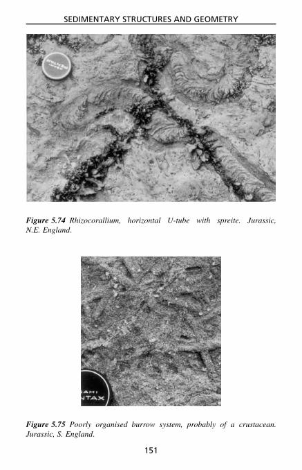
SEDIMENTARY STRUCTURES AND GEOMETRY
Figure 5.74 Rhizocorallium, horizontal U-tube with spreite. Jurassic,N.E. England.
Figure 5.75 Poorly organised burrow system, probably of a crustacean.Jurassic, S. England.
151

SEDIMENTARY STRUCTURES AND GEOMETRY
When burrowing organisms are rapidly buried, some can move up toregain their position relative to the sediment–water interface; in so doingthey leave behind a characteristic escape structure which deflects adjacentlaminae to give a chevron structure.
Other burrows, particularly those of crustaceans, are simple to irregularlybranching systems, with walls composed of pellets or clay (e.g., Ophiomorphaand Thalassinoides, Figs. 5.69 and 5.72). Some dwelling burrows possesscurved laminae (meniscate) (Fig. 5.72), indicating backfilling by the animalas it moved through the sediment (e.g., Beaconites, a lungfish burrow foundin fluvial sediments).
Feeding structures are trace fossils developed within the sediment bydeposit-feeding organisms searching for food. One of the commonest is asimple, non-branching, backfilled horizontal to subhorizontal burrow (diam-eter 5 to 20 mm); some are composed of a series of sand balls, giving abeaded appearance (e.g., Eione, Fig. 5.76). Other feeding burrows are highlyorganised, in some cases with regular branching patterns (e.g., Chondrites,Fig. 5.77), in others with regular changes of direction, produced by the organ-ism systematically working the sediment (e.g., Zoophycos, Fig. 5.78).
Burrow structures within a bed commonly descend from the bedding planeabove, which was the sediment surface when the burrowing organisms were
Figure 5.76 Eione, a burrow containing balls of sand, giving a beadedappearance, the result of the animal ingesting and excreting the sand (toremove the organic matter) as it burrowed through the sediment. Field ofview 20 cm across. Carboniferous, N.E. England.
152

SEDIMENTARY STRUCTURES AND GEOMETRY
Figure 5.77 Chondrites, a feeding burrow system. Field of view 30 cm across.Devonian, S.W. England.
Figure 5.78 Zoophycos, a feeding burrow system. Field of view 20 cm across.Carboniferous, N.E. England.
153

SEDIMENTARY STRUCTURES AND GEOMETRY
active. In some beds there may be a number of different burrow structures,occurring at different depths relative to the original seafloor. This is referredto as a tiering of the trace fossils. Look for the presence of different bur-rows, e.g., large ones and small ones, lined and unlined, simple tubes andmany branches, stuffed and simply filled, and for one type of burrow cross-cutting another.
Borings, traces made in solid rock or a fossil, vary in shape from tubu-lar structures to oval/round holes, all generally filled by sediment. In somecases the host sediment has been weathered away to leave the borings stand-ing proud. Borings made by lithophagid bivalves have a distinctive round-bottomed flask shape (Fig. 5.79) and the shell itself may still be present.Sponge borings tend to have a beaded appearance, whereas annelid (poly-chaete) borings are more uniform tubes.
Borings are common in hardground surfaces (see Figs 5.43 and 5.44 andSection 5.4.3) and are important evidence that the seafloor was cementedduring deposition. Look for the borings cutting shells within the limestone andpenetrating shells encrusting the hardground surface. Pebbles and intraclastsin shallow-marine sediments are commonly bored (e.g., Fig. 5.79) and manylarger fossils, such as corals, echinoids and oysters, may also show the effectsof boring organisms.
Figure 5.79 Borings (1 cm long) of lithophagid bivalves in a dolomite pebbleof a beach conglomerate. Miocene, Mallorca, Spain.
154

SEDIMENTARY STRUCTURES AND GEOMETRY
5.6.3 Use of trace fossils in sedimentary studiesBiogenic sedimentary structures can give vital information for environmentalinterpretation, in terms of water depth, salinity, energy level, oxygenation,etc., and they are especially valuable where body fossils are absent. It maybe possible to recognise different suites or assemblages of trace fossil in asedimentary succession so that ichnofacies can be distinguished. Four majormarine ichnofacies are recognised, named after the typical trace fossil present,occurring in littoral (Skolithos ichnofacies), sublittoral (Cruziana), bathyal(Zoophycos) and abyssal (Nereites) zones. See Table 5.10 for further infor-mation on these trace fossil assemblages, their depositional environments andfacies context.
Although particular trace fossils are typically found in a certain facies,similar conditions can exist in other environments, so that the same tracefossils occur there too. The trace fossils may not necessarily have been madeby the same animals, of course – it is just that they had the same behaviour.Thus, for example, ichnofossils typical of moderate to low energy, quiet,deepish water, such as those of the Cruziana and Zoophycos ichnofacies,may occur in shallow-water lagoonal facies too.
Trace fossils can give an indication of sedimentation rate. Intensely biotur-bated horizons and beds with well-preserved, complex feeding and grazingtraces would generally reflect slow rates of sedimentation; bored surfaces(hardgrounds, Section 5.4.3) generally indicate a break in sedimentation (ahiatus or omission surface) allowing seafloor cementation to take place.Intense bioturbation may occur immediately below a flooding surface, where,for example, sandstones are sharply overlain by deeper-water mudrocks.U-shaped burrows with spreite and escape structures reflect more rapid sed-imentation.
trace
undertrace
Figure 5.80 Trace made by animalon sediment surface transferred tolower laminae to form undertrace.
Trace fossils can give an indi-cation of sediment consistency. Fivestates are recognised: soupground,softground, looseground, firmgroundand hardground (Table 5.11). If thesediment is soft, then tracks made ona lamina can be transmitted throughto underlying laminae (Fig. 5.80).Where burrows are either filled withcoarser sediment or preferentiallylithified during early diagenesis, surrounding sediments are commonly com-pacted around the burrow fills if the sediment was a softground. In firm-grounds the burrows show little compaction, and hardgrounds are recognisedby the presence of borings and encrusting organisms.
155

SEDIMENTARY STRUCTURES AND GEOMETRY
Tabl
e5.
10Tr
ace-
foss
ilas
sem
blag
es(i
chno
faci
es),
depo
siti
onal
envi
ronm
ents
,fac
ies
cont
ext,
typi
cal
trac
e-fo
ssil
type
san
dic
hnof
ossi
lex
ampl
es.
Skol
itho
sC
ruzi
ana
Zoo
phyc
osN
erei
tes
Ass
embl
age
Ass
embl
age
Ass
embl
age
Ass
embl
age
Sand
ysh
orel
ine,
fore
shor
ean
dsh
oref
ace,
0–
10m
dept
h,hi
ghen
ergy
Subl
ittor
alzo
ne,
offs
hore
inne
rsh
elf,
∼10
–10
0m
dept
h,al
sola
goon
s
Bat
hyal
zone
,ou
ter
shel
f,sl
ope,
shal
low
basi
n,∼1
00–
2000
mde
pth,
also
lago
ons
Bat
hyal
/aby
ssal
zone
,de
epse
afloo
r,∼1
000
–50
00m
dept
h
Fac
ies:
flat
-bed
ded,
cros
s-be
dded
med
ium
/coa
rse
sand
ston
esan
dgr
ain/
pack
ston
es
Fac
ies:
para
llel-
and
cros
s-la
min
ated
fine
sand
/silt
ston
es,
pack
/wac
kest
ones
and
mud
rock
s
Fac
ies:
lam
inat
edfi
nesa
nd/s
iltst
ones
,m
udro
cks
and
wac
ke/m
udst
ones
Fac
ies:
mud
rock
san
dlim
em
udst
ones
with
orw
ithou
ttu
rbid
ites
Low
dive
rsity
,ve
rtic
albu
rrow
s,si
mpl
e,U
-sha
ped,
pelle
t-lin
ed
Wid
eva
riet
yof
surf
ace
trac
ksan
dtr
ails
,co
mpl
exbu
rrow
s
Lim
ited
num
ber
offe
edin
gan
dgr
azin
gtr
ails
and
burr
ows,
som
eco
mpl
ex
Reg
ular
patt
erns
onse
dim
ent
surf
ace,
ofte
nse
enon
bed
unde
rsur
face
Skol
itho
s,O
phio
mor
pha,
Dip
locr
ater
ion,
Mon
ocra
teri
on
Cru
zian
a,A
ster
iaci
tes,
Rhi
zoco
rall
ium
,Eio
ne,
Cho
ndri
tes,
Pla
noli
tes,
Tha
lass
inoi
des
Zoo
phyc
os,P
hyco
siph
on,
Spir
ophy
ton
Ner
eite
s,H
elm
inth
oide
s,P
alae
odic
tyon
,Sp
iror
haph
e
156

SEDIMENTARY STRUCTURES AND GEOMETRY
Table 5.11 Types of substrate and their recognition from trace fossils.
Sedimentconsistency
Nature of originalsediment
Trace fossilsand features
Soupground water-saturated,clay-rich sediment
trace fossils highlycompressed andsmeared
Softground soft mud substantial compactionof burrows soindefinite outlines
Looseground loose sorted sandand silt
burrows well defined,often with linings orpelleted walls, somecompaction
Firmground stiff substrate, e.g.muddy sand
burrow outlines sharpand minor compaction
Hardground seafloor-cementedsediment, usuallylimestone
borings cuttingsediment andgrains/fossils,encrusting fossils,clasts
Bedding-plane trace fossils may show a preferred orientation, reflectingcontemporaneous currents (bivalve resting traces commonly show this, forexample). Some trace fossils (footprints, U-shaped and escape burrows) canbe used to show the way-up of strata.
See the References and Further Reading for more information.
5.6.4 Rootlet bedsRoot systems of plants disrupt the internal structure of beds in a similar wayto burrowing animals. Many roots and rootlets are vertically arranged whereasothers are horizontally disposed; many branch freely. Roots are commonlycarbonised, appearing as black streaks; many are preserved as impressions,but some roots are preserved as casts, consisting of sandstone (e.g., Stig-maria). The identification of rootlet beds indicates in situ growth of plantsand soil development, and thus subaerial conditions; coal seams may occurabove such rootlet beds (see Section 3.10).
Plant debris is easily transported, however, so that plant-rich sedimentsare common. Examine a plant bed for rootlets; if it is just a collection ofplant debris washed in, much of the material will be of the subaerial partsof the plant: leaves and branches. Sea-grass, growing in several metres of
157

SEDIMENTARY STRUCTURES AND GEOMETRY
water, common today, evolved in the Tertiary so that their rootlets would notindicate subaerial exposure.
Where plants have been growing in a semi-arid environment, calcretesmay develop within the soil profile and the plant roots may then becomecalcified to form rhizocretions (see Fig. 5.63, Section 5.5.6.2).
5.7 Geometry of Sedimentary Deposits and Lateral FaciesChanges
Some sedimentary rock units can be traced over large areas and show littlechange in character (that is, facies) or thickness; others are laterally impersis-tent. The geometry of sedimentary deposits should be considered on the scaleof the individual bed or rock unit as seen in an exposure and on a larger,more regional scale, in terms of the shape of the sediment body or packageof a particular lithofacies or group of related lithofacies.
bed/rock unit geometry (small scale)
sediment body geometry (large scale)
tabular lenticularwedge-shaped
sheet cone/fanlens/patch
ribbon/shoestring beltdendroid
Figure 5.81 Common geometries ofbeds or rock units (on a scaleof metres to tens of metres) andsediment bodies (on kilometre orregional scale).
5.7.1 Sediment bodygeometries
The geometry of an individual bed orrock unit can be described as beingtabular if laterally extensive, wedge-shaped if impersistent but with pla-nar bounding surfaces, and lenticularif one or both of the bounding sur-faces is curved (Fig. 5.81). For thelarger scale, the term sheet (or blan-ket) is often applied if the length-to-width ratio of the sedimentary unitis around 1:1 and the sediment bodycovers a few to thousands of squarekilometres. Elongate sediment bod-ies, where the length greatly exceedsthe width, can be described as lin-ear (also ribbon or shoestring) ifunbranching, dendroid if branching,and a belt if composite. Many elon-gate sand bodies are channel fills,oriented down the palaeoslope. Elon-gate sediment bodies can also form
parallel to a shoreline, as in beach and barrier island developments. Sedi-mentary units can be discrete entities forming lenses and patches, the latterterm being particularly applicable to some reef limestones. Coarse clastic
158

SEDIMENTARY STRUCTURES AND GEOMETRY
sediments may form fans, wedges and aprons where deposited at the toe ofa slope. Examples include alluvial fan, fan-delta, toe-of-slope and submarinefan deposits.
Facies, defined by the lithological, textural, structural and palaeontolog-ical features of the sedimentary rock, commonly change laterally as well asvertically in a sedimentary succession. This can involve a change in one or allof the parameters defining the facies. Lateral changes can be very rapid, overseveral or tens of metres, or more gradational, when the change takes placeover several kilometres. Facies changes reflect changes in the environmentalconditions of sedimentation (Chapter 8).
Observations of the geometry of individual beds and rock units normallypresent no problem. In a quarry or cliff exposure, follow beds laterally todetermine their shape and then make notes and sketches (or take photographs).With the larger-scale geometry of sediment bodies, if exposures are very goodas in some mountainous and vegetation-free regions, it may be possible tosee the lateral changes and sediment-body shape directly, and to see therelationships between sedimentary units. Where exposure is limited, makedetailed logs across the same part of the rock succession at several or manylocalities. To be sure that sections are equivalent, it is necessary to haveeither a laterally continuous horizon in the succession (a marker bed), or thepresence of the same zonal fossils. If lateral facies changes are suspected inan area of poor exposure then detailed mapping and logging of all availableexposures may be required to demonstrate such changes.
5.7.2 Stratigraphic relationships:offlap, downlap, onlapand truncation
truncation onlap
downlap
Figure 5.82 Relationships betweensedimentary units: truncation, onlapand downlap.
From the study of seismic sections,several types of large-scale relation-ship between sediment bodies havebeen noted: truncation, onlap, down-lap, offlap and toplap (Fig. 5.82). Itis important to be able to documentsuch relationships in a succession,since they relate to changes in rel-ative sea level and accommodation space (concepts used in sequence stratig-raphy: see Sections 2.10.2 and 8.4). However, in the field, they are rarelyseen unless large coastal or mountainside cliff exposures are available; theymay be revealed by regional stratigraphic studies and mapping.
Downlap may be seen as gently to steeply dipping surfaces (the clinoformsdescribed in Section 5.3.3.14, for example, are downlapping beds: Figs 5.33
159

SEDIMENTARY STRUCTURES AND GEOMETRY
Figure 5.83 Massive reef limestone (left) with offlapping reef-debris bedsdownlapping to the right onto condensed deeper-water limestone. Cliff is 40 mhigh. Triassic, Catalonia, Spain.
and 5.83), and the downlap surface may be visible. Downlap–offlap repre-sents progradation of a sedimentary unit and the downlap surface itself isusually a thin, condensed bed or sediment-starved horizon with much bio-turbation, perhaps with glauconite or phosphorite. In some instances withclinoforms, toplap may be visible.
Onlap of one sedimentary unit onto or against another is a common large-scale arrangement but again it is rarely observed in one exposure. It can beseen where strata gradually bury a unit with topographic expression, suchas a carbonate platform margin or reef (Fig. 5.84), or where strata fill alarge, broad channel structure and lap up onto its margin, or where strataonlap a tilted surface (Fig. 5.85). However, onlap on a larger scale can bedemonstrated by determining the age of the base of a stratigraphic unit overa large area, when it may then be apparent that it youngs in a particulardirection, i.e., it is onlapping the underlying strata that way. The nature ofthe onlap surface itself (which may be an unconformity) may also changelaterally; for example, it may become a more prominent palaeokarst in thedirection of onlap. Onlap of this type in marine strata reflects a relativerise of sea level and the onlap surface may be a sequence boundary and/ortransgressive surface (see Section 8.4).
A truncation surface is where strata are cut off beneath a prominentbedding plane. Again this may be visible in good outcrops but commonlyit is on a larger scale, and examining exposures over a large area may benecessary to identify this type of stratigraphic boundary (an unconformity).Truncation surfaces are the result of uplift, perhaps folding, and erosion ofstrata. Truncated surfaces may also be onlap surfaces, with the sediments
160

SEDIMENTARY STRUCTURES AND GEOMETRY
Figure 5.84 Massive reef limestone (left) being onlapped by youngerfine-grained limestones. Later compaction has accentuated the dip of theonlapping strata. Height of reef 30 m. Triassic, Catalonia, Spain.
Figure 5.85 Onlap of sedimentary strata. Notice the subtle discontinuitywithin this package of shallow-water limestones and mudrocks. Height of cliff80 m. Jurassic, Mareb, Yemen.
161

SEDIMENTARY STRUCTURES AND GEOMETRY
immediately beneath the surface getting older in the direction of younging ofthe overlying unit. This would reflect the increased time for erosion of therocks below the onlapping unit.
For these larger-scale relationships between stratigraphic units, look care-fully at the bedding planes in a good outcrop and follow them along.
• Is there any gentle dip of beds down to a surface? This would be down-lap (downlap may involve more steeply dipping beds but this shouldbe obvious).
• Is there any truncation of underlying strata up to a prominent beddingplane? This would indicate an unconformity.
• Laterally, does a bed overlap the one below onto a prominent surface?This would be onlap.
These may all be very subtle arrangements so that you may need to studythe exposure carefully, perhaps by standing back or by using binoculars oncliff-faces, to see these features. Bear in mind, however, that these angularrelationships between stratigraphic units depend on the plane of the section,and with some outcrops there is the problem of perspective, such as whenlooking up to high cliffs, for example.
162

6FOSSILS IN THE FIELD
6.1 IntroductionFossils are an important component of sedimentary rocks. First and foremost,they can be used for biostratigraphic purposes to determine the relative ageof the rock succession and for correlations with successions elsewhere. Theidentification of fossils to the species level is not easy and in most cases isbest left to the specialist. However, there are various fossil handbooks and theTreatise of Invertebrate Paleontology which can be used to identify fossils.
Fossils are of great use in the environmental interpretation of sedimentaryrocks, and in this context many useful observations can be made in the fieldby the non-specialist with a keen eye. Fossils can tell you about the waterdepth, level of turbulence, salinity and sedimentation rate; they can recordpalaeocurrent directions and give information on palaeoclimatology. In somecases the whole environmental interpretation of a sedimentary succession maydepend on the presence of just a few fossils, and occasionally an interpreta-tion has been shattered by the discovery of new fossils. Field observationson fossils should consider their distribution, preservation (taphonomy) andrelation to the sediment, their associations and diversity.
A checklist for the examination of fossils in the field is given in Table 6.1and the distribution, diversity and abundance of the main fossil groups throughthe Phanerozoic is shown in Fig. 6.1. In Precambrian strata only microbiallaminites and stromatolites are seen in the field.
6.1.1 MacrofossilsMacrofossils are big enough to see in the field and with a little experienceor training in palaeontology it is relatively easy to identify the animal groupto which they belong, and in some cases even to apply a species name. Thecommon fossil types you should be able to recognise easily in marine Palaeo-zoic strata are the trilobites, graptolites, brachiopods, gastropods, ammonoids,orthocones, rugose corals, tabulate corals, bryozoans, stromatoporoids andcrinoids. In Mesozoic strata the common marine fossils are brachiopods,bivalves (including the rudists in the Cretaceous), gastropods, scleractiniancorals, crinoids, echinoids (especially in the Cretaceous), ammonites, belem-nites and calcareous algae. In Cenozoic strata, you should find abundant
Sedimentary Rocks in the Field. Maurice E. Tucker 2003 John Wiley & Sons, Ltd ISBN: 0-470-85123-6
163

FOSSILS IN THE FIELD
Table 6.1 Checklist for the examination of fossils in the field. A: Distributionof fossils in sediment; B: fossil assemblages and diversity; C: diagenesis offossil skeletons.
A: Distribution of fossils in sediment1. Fossils largely in growth position
(a) Do they constitute a reef? Reefs are characterised by colonialorganisms, interaction between organisms (such as encrustinggrowth), presence of original cavities (filled with sediment and/orcement) and massive, unbedded appearance (Section 3.5.3):(i) Describe growth forms of colonial organisms (see
Fig. 3.13); do these change up through the section/reef?(ii) Are some skeletons providing a framework?
(b) If non-reef, are fossils epifaunal or infaunal? If epifaunal, howhave fossils been preserved: by smoothering, for example?
(c) Do epifaunal fossils have a preferred orientation, reflectingcontemporary currents? If so, measure orientation.
(d) Are fossils encrusting substrate, i.e., is it a hardground surface?(e) Are the plant remains rootlets?
2. Fossils not in growth position(a) Are they concentrated into lenses, pavements or stringers, or are
they laterally persistent beds or evenly distributed throughout thesediment?
(b) Do fossils occur in a particular lithofacies? Are there differencesin the faunal content of different lithofacies?
(c) If fossil concentrations occur, what proportion of fossils arebroken and disarticulated? Are delicate skeletal structurespreserved, such as spines on shells? Check sorting of fossilsand degree of rounding; look for imbrication, graded bedding,cross-bedding, scoured bases and sole structures.
(d) Do fossils show a preferred orientation? If so, measureorientation.
(e) Have fossils been bored or encrusted?(f) Note degree of bioturbation, ichnofabric and any specific trace
fossils present.
B: Fossil assemblages and diversity1. Determine the composition of the fossil assemblage by estimating the
relative abundance of the different fossil groups in a bed or on abedding plane.
164

FOSSILS IN THE FIELD
Table 6.1 (continued)
2. Is the fossil assemblage identical in all beds of the section or areseveral different assemblages present? if the latter, do the assemblagescorrelate with different lithofacies?
3. Consider the degree of reworking and transportation; does the fossilassemblage reflect the community of organisms which lived in thatarea?
4. Consider the composition of the fossil assemblage. For example, isit dominated by only a few species? Are they euryhaline or stenoha-line? Are certain fossil groups conspicuous by their absence? Do allfossil groups present have a similar mode of life? Do pelagic formsdominate? Are infaunal organisms absent?
C: Diagenesis of fossil skeletons1. Is original mineralogy preserved or have skeletons been replaced:
calcified, dolomitised, silicified, hematised, pyritised, etc.?2. Have fossils been dissolved out to leave moulds?3. Do fossils occur preferentially in nodules?4. Are fossils full-bodied or have they been compacted?
ERA
C
M
P
PLANKTONIC BENTHIC
Dominant Important Minor
Coc
colit
hs
For
ams
For
ams
Cor
allin
ere
d al
gae
Gre
enal
gae
Biv
alve
s
Gas
trop
ods
Cor
als
Trilo
bite
s
Bra
chio
pods
Bry
ozoa
ns
Crin
oids
Ech
inoi
ds
Figure 6.1 The distribution, abundance (shown by shading) and diversity(shown by width) of the main fossil groups through the Phanerozoic.
165

FOSSILS IN THE FIELD
bivalves and gastropods, along with scleractinian corals and calcareous algae.Other macrofossil groups, such as vertebrates and crustaceans, are rarelyfound. Plant fossils are abundant in certain strata, mostly non-marine facies.
6.1.2 MicrofossilsThese are not usually seen in hand-specimens, except in rare cases as grainsunder a hand-lens (e.g., foraminifera and radiolarians) or in particular hori-zons where large forms of microfossil have developed, e.g., the nummuliteforams in Eocene rocks (see Fig. 6.6 below). You can collect material formicrofossil extraction back in the laboratory and then a sample of 0.5–1 kgis usually sufficient. Microfossils can be studied in thin sections of the rock,but many need to be extracted whole and viewed with a binocular micro-scope or SEM. Conodonts in Palaeozoic strata are obtained by dissolvinglimestones in dilute acid, and spores in post-Devonian strata are extractedwith hydrofluoric acid, HF (be careful!). Foraminifera, ostracods, etc., can beremoved from weakly cemented chalk and mudrock by crushing, sieving andultrasound or by repeated boiling and freezing. See micropalaeontologicaltexts for techniques.
Microfossils can be particularly useful for biostratigraphic correlation,since the particular forms present depend on the age and facies. They can alsobe used in palaeoenvironmental studies, for example to separate marine fromnon-marine facies, or hypersaline from hyposaline, or shallow from deep.
6.2 Fossil Distribution and PreservationPay attention to the distribution of the fossils while studying or logginga succession of sediments. Fossils can be evenly distributed throughout arock unit without any preferential concentration in certain beds; this gener-ally occurs only where the sediment is homogeneous throughout. Use thepercentage charts in Fig. 3.3 to estimate the proportions of the various fos-sils present.
In many cases, fossils are not evenly distributed but occur preferentiallyin certain beds or lenses, or in a buildup (a reef). The term coquina (andlumachelle) is often used for an accumulation of shells. Always examine thetypes of fossil present and determine their relative distribution. See whetherthere is a correlation between fossil type and lithofacies. Concentrationsof fossils at particular levels can arise from current activity or preferentialgrowth through favourable environmental conditions.
Fossils can be arranged in several different ways within a bed: concordant,oblique, perpendicular, imbricated, stacked and nested (see Fig. 6.2, and seeFig. 6.3 for an example). Examine the fossiliferous bed in cross-section and
166

FOSSILS IN THE FIELD
Bedding cross-section
Bedding plane view
concordant oblique perpendicular
pavement stringer preferred orientation
imbricatedcurrent
stacked nested
Figure 6.2 The various arrangements of fossils in sedimentary rocks as seenon bedding planes and in bed cross-sections.
determine the orientation of the fossils; this depends on the levels of currentactivity and sorting (see below).
On the bedding planes, fossils may be arranged as a carpet or pavementa few valves thick, all lying flat upon the surface, or they may form a linearfeature on the surface, a stringer or low ridge (Fig. 6.2), concentrated thereby currents.
6.2.1 In situ fossil accumulationsWhere favourable conditions existed, some fossils will be preserved intact,with little breakage or disarticulation, and at least some of the organismswhich lived on or in the sediment will be in their life position. Fossils whichare commonly found in their growth position include brachiopods (Fig. 6.4),some bivalves (especially the rudists), corals (Fig. 6.5), bryozoans and stro-matoporoids. It is worth noting the general level of infaunal activity (theamount of bioturbation and the ichnofabric, see Section 5.6.1, Fig. 5.68) inconjunction with the body fossils present.
167
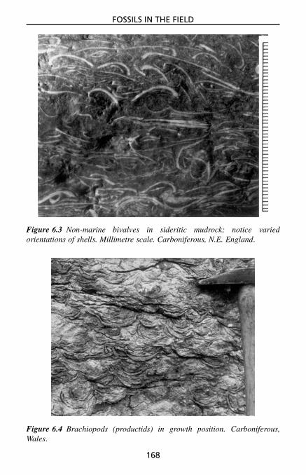
FOSSILS IN THE FIELD
Figure 6.3 Non-marine bivalves in sideritic mudrock; notice variedorientations of shells. Millimetre scale. Carboniferous, N.E. England.
Figure 6.4 Brachiopods (productids) in growth position. Carboniferous,Wales.
168

FOSSILS IN THE FIELD
Figure 6.5 Colonial corals in growth position. Carboniferous, Wales.
Fossils can be organised into reefs (the more general term is buildup)(Section 3.5.3). In these the majority of the fossils are in their growth position,perhaps with some organisms growing over and upon each other. Colonialorganisms can dominate and the rock characteristically has a massive, unbed-ded appearance (Figs 3.11, 3.12, 5.83 and 5.84). The fossils commonly havea variety of growth forms (shapes), depending on the environmental con-ditions (Fig. 3.13), and there may be an upward change through the reef.Cavities, both large and small, perhaps filled with internal sediment and cal-cite cement, are common in reefal limestones (e.g., Fig. 3.9).
Hiatal concentrations are fossil accumulations as a result of minimaldeposition of mud and sand. The fossils may be bored, encrusted, discolouredor phosphatised, and authigenic minerals such as chamosite and glauconitemay be present. These beds are usually highly condensed and biozones maybe missing.
6.2.2 Current accumulations of fossilsConcentrations of skeletal material arising from current activity can form ina number of ways. Transportation of skeletal debris by storm currents leadsto the deposition of storm beds (also called tempestites: see Section 5.3.3.9,Fig. 5.29). These event beds tend to be quite laterally persistent and possesssharp, usually scoured bases. Internally, they vary from laminated beds with
169

FOSSILS IN THE FIELD
normal size-grading and good sorting of fossils, to beds and lenses with noapparent sorting of fossils, the deposit having a ‘dumped’ appearance with awide range of grain-sizes and no internal structure. Examine the arrangementof fossils in the storm beds by reference to Fig. 6.2.
Fossil accumulations can also form through the winnowing action ofweaker currents which remove finer sediment and skeletal grains. Such fossillag deposits are usually impersistent lenses; they too occur in shallow-shelfsuccessions, especially at transgressive surfaces. Fossil-rich beds can also beformed through reworking of sediment by laterally migrating tidal channels.
The degree of current activity and reworking affects the proportion of bro-ken and disarticulated carbonate skeletons within a fossil concentration. Withan increasing level of agitation, fossils grade from perfect preservation, withall delicate structures intact and adjoined, to poor preservation where fossilsare abraded and broken. Points to look for with specific fossils are as follows.
• Crinoids : the length of the stems and whether all ossicles are separated;if the calyx is present whether this is attached to the stem or not
• Bivalved shells (bivalves, brachiopods and ostracods): whether the valvesare disarticulated or articulated; if the former, whether there are equalnumbers of each valve; if the latter, whether the valves are open or closed
• Some brachiopods and bivalves : whether the spines for anchorage arestill attached
• Trilobites : whether the exoskeleton is whole or incomplete (e.g.,only tails).
6.2.3 Preferred orientations of fossilsElongate shells or skeletons affected by currents commonly have a preferredorientation of their long axes (Figs 6.6 and 6.7). This alignment is generallyparallel to the current, or less commonly normal to the current if the skeletalfragments were subject to rolling. Preferred orientations are commonly foundwith crinoid stems, graptolites, cricoconarids (tentaculitids), elongate bivalveshells, solitary corals, belemnites, orthoconic nautiloids and plant fragments.Some fossil orientations may reflect current directions during life. In a col-lection of elongate fossils on a bedding plane, measure their orientation.Chapter 7 deals with palaeocurrent analysis.
6.3 Fossil Associations and Diversity6.3.1 Fossil assemblagesThe fossil assemblages present, and their relationships to each other, giveuseful environmental information. First, determine the fossil assemblage qual-itatively by estimating the relative abundance of the different fossil groups.For a precise analysis of the assemblage, large blocks of the sediment need
170

FOSSILS IN THE FIELD
Figure 6.6 Nummulite foraminifers with preferred orientation. Field of view4 cm. Tertiary, French Alps.
Figure 6.7 Graptolites showing a preferred orientation. Millimetre scale.Ordovician, Wales.
171

FOSSILS IN THE FIELD
to be broken up carefully and all species identified and counted. This is bestundertaken in the laboratory. If good bedding-plane exposures are available,count the number of each fossil species in a quadrat, a square of a particu-lar area; one square metre is usually taken. Plot the data in a histogram orpie diagram.
By carefully analysing the fossil assemblage from different beds in asection or different but coeval lithofacies over an area, changes in the assem-blage can be recognised. Assemblages can be described by their dominantmembers; choose one or several of the characteristic forms present, e.g.productid–coral assemblage (common in Lower Carboniferous limestones)or echinoid–terebratulid–sponge assemblage (common in the Upper Creta-ceous chalks).
A fossil assemblage is also a death assemblage. Many such assemblagesare composed of the remains of animals which did not live in the samearea. The skeletal debris would have been brought together by currents andso generally consists of broken and disarticulated skeletons. However, somedeath assemblages consist of the skeletons of organisms which did live in thesame general area. In these cases, some fossils may occur in their originallife position and skeletal transportation would have been minimal. Reefs andother buildups are obvious examples of in situ death assemblages.
Where little transport of skeletal material has taken place after death, thefossil assemblage will reflect the community of organisms which lived inthat area. A community can be referred to either by a dominant species, inthe same way as an assemblage, or by reference to the lithofacies (e.g., amuddy sand community). The ascribing of an assemblage to a community isan important step, since a community is dependent on environmental factorsand changes in community can indicate changes in the environment. Once acommunity has been recognised, it is possible to look at the species presentand deduce the roles the various organisms played in that community.
It must be remembered that much, if not most, of the fossil record isnot preserved. There is obviously a bias towards the preservation of animalhard parts. In studying a community, thought should be given to animals andplants for which there is only circumstantial or no evidence. Trace fossils,pellets, coprolites and microbial laminae are important in this respect.
One feature to look for in an assemblage is the presence of encrustingand boring organisms. Large skeletal fragments can act as substrates forothers; oysters, bryozoans, barnacles, certain inarticulate brachiopods, algaeand serpulid worms commonly encrust other skeletons (e.g., Fig. 6.8). Boringorganisms such as serpulids, lithophagid bivalves and sponges can attackskeletal fragments and other hard substrates (such as hardground surfaces,Fig. 5.44; see Sections 5.4.3 and 5.6.2) and pebbles in beach gravels (seeFig. 5.79), producing characteristic holes and tubes. Boring and encrusting
172

FOSSILS IN THE FIELD
Figure 6.8 Echinoid test encrusted with serpulid worm tubes, bryozoans andoyster. Millimetre scale. Cretaceous, E. England.
of skeletal debris tend to be more common where sedimentation rates are low.Burrows in sediment are also more common in such situations (Section 5.6).
6.3.2 Fossils as environmental indicatorsThe number and type of species present in an assemblage depend on envi-ronmental factors. Where these factors (depth, salinity, agitation, substrate,oxygenation, etc.) are at an optimum, there is maximum species diversity.Infaunal and epifaunal benthic (bottom-dwelling), nektonic (free-swimming)and planktonic (free-floating) organisms are all present. Where there are envi-ronmental pressures, species diversity is lowered and certain aspects of thefauna and flora may be missing. However, in these situations, species thatare present and can tolerate the environment may occur in great numbers.With increasing depth, pelagic fossils will dominate, such as fish, graptolites,cephalopods, planktonic foraminifera, posidonid bivalves and some ostra-cods. The same situation is found with an increasing degree of stagnation:benthic organisms will eventually be excluded altogether, so that only pelagicorganisms are present.
6.3.2.1 Fossils and salinityWith higher or lower salinities than normal marine, many species are excludedcompletely. Groups tolerant of normal-marine conditions only (stenohalineforms) are corals, bryozoans, stromatoporoids and trilobites; many specificgenera and species of other groups are also stenohaline. Some fossil groups
173

FOSSILS IN THE FIELD
(euryhaline forms) are able to tolerate extremes of salinity; certain bivalves,gastropods, ostracods and charophyte algae are examples. Where sedimentscontain large numbers of only a few species of such groups, then hypersalineor hyposaline conditions should be suspected. In some cases, organism skele-tons show a change in shape or size with extremes of salinity. Hypersalineconditions may well be indicated by the presence of evaporite pseudomorphs(Section 3.6).
6.3.2.2 Fossils and depthDepth of deposition is best inferred from sedimentary structures and facies;fossils can give an indication but rarely anything precise. Many benthic fossils(brachiopods, bivalves, gastropods, corals, etc.) are typical of nearshore, agi-tated shallow-water environments, depths less than 20 m say, although theymay occur in deeper water too, but then generally in smaller numbers. Otherfossils are more typical of the quieter, muddy shelf environment. As waterdepth increases, benthic fossils decrease in abundance and pelagic fossilsbecome more common. The photic zone, around 100–200 m deep (depend-ing on water clarity), could be recognised by the disappearance of algae, butthere are actually few algal species living near this depth anyway.
In deeper water, the aragonite compensation depth (ACD) is the nextthreshold, at a few hundred to 2000 m, below which aragonite shells are notpreserved and the fossils are only casts. Ammonites in pelagic limestones canbe preserved in this way. The calcite compensation depth (CCD) is at severalthousand metres and below this no calcareous fossils are found; siliceousshales and cherts will be the typical sediments with only non-calcareousfossils (e.g., radiolarians and phosphatic ammonite aptychi).
6.3.2.3 Fossils (and trace fossils) and oxygenThe amount of oxygen in seawater and sediment porewater is an importantfactor controlling the organisms present, their preservation and the sedi-mentary facies. Five classes of oxygen-related facies are distinguished, withincreasing oxygen content–anaerobic, quasi-anaerobic, exaerobic, dysaerobicand aerobic – and they have different trace fossils, body fossils and sedimenttextures and composition (Table 6.2). The degree of oxygenation is deter-mined by water circulation, organic matter and sediment supply rates, andwater depth.
The typical fossils and their occurrence in the major marine facies areshown in Table 6.3.
6.4 Skeletal DiagenesisThe original composition of fossil skeletons is commonly altered during dia-genesis. Many carbonate fossil skeletons were composed of aragonite when
174

FOSSILS IN THE FIELD
Tabl
e6.
2F
ossi
ls,i
chno
fabr
ics/
trac
efo
ssil
san
dox
ygen
:ox
ygen
-rel
ated
faci
es.
Oxy
gen-
rela
ted
faci
esB
ody
foss
ilsIc
hnof
abri
cSe
dim
ent
Ana
erob
icno
bent
hic
foss
ils,
wel
l-pr
eser
ved
pela
gic
foss
ils
notr
ails
orbu
rrow
s,fa
ecal
mat
eria
lw
ell-
lam
inat
ed,
orga
nic-
rich
,bl
ack
mud
s
Qua
si-a
naer
obic
few
mic
robe
nthi
cfo
ssils
,w
ell-
pres
erve
dpe
lagi
cfo
ssils
mic
robi
otur
batio
nfa
ecal
mat
eria
lw
ell-
lam
inat
ed,
orga
nic-
rich
,bl
ack
mud
s
Exa
erob
icso
me
insi
tuep
iben
thic
mac
rofo
ssils
,sm
all
size
,lo
wdi
vers
ity
few
shal
low
burr
ows,
som
etr
ails
lam
inat
edda
rkgr
eym
uds/
sand
s
Dys
aero
bic
low
dive
rsity
,sm
all
mac
robe
nthi
cs,
thin
shel
lsm
ore
shal
low
burr
ows,
som
ede
eper
;tr
ails
biot
urba
ted
lam
inae
and
beds
ofgr
eym
ud/s
and
Aer
obic
dive
rse,
larg
em
acro
bent
hics
,he
avy
shel
lstr
ace
foss
ilsm
aybe
abun
dant
and
dive
rse,
tieri
ng
biot
urba
ted
stra
ta,
plus
othe
rse
dim
enta
ryst
ruct
ures
:ri
pple
s,cr
oss-
bedd
ing,
etc.
175

FOSSILS IN THE FIELD
Tabl
e6.
3T
hem
ain
foss
ilco
mpo
nent
san
dpr
eser
vati
onin
mar
ine
faci
es.
Fac
ies
Lit
holo
gies
Fos
sils
Div
ersi
tyA
bund
ance
Taph
onom
y
Lag
oona
lfa
cies
,be
hind
barr
ier
orre
ef
fine-
grai
ned
clas
tics
and
carb
onat
es,
som
eco
arse
rse
dim
ents
from
shel
fby
stor
ms
biva
lves
,ga
stro
pods
,os
trac
ods,
trac
efo
ssils
com
mon
low
vari
able
,bu
tm
aybe
high
insi
tufa
unas
,so
me
shel
lbe
ds,
intr
oduc
edfo
ssils
from
shel
fby
stor
ms
Shor
elin
e,be
ach
and
shor
efac
esa
ndst
ones
/gra
inst
ones
,pl
uscr
oss-
bedd
ing,
SCS,
HC
S
brac
hiop
ods,
biva
lves
,ga
stro
pods
,bu
rrow
slo
wm
ostly
low
insi
tufa
unas
rare
,sk
elet
alde
bris
Shor
efac
e/in
ner–
mid
shel
fsa
ndst
ones
/gra
inst
ones
inst
orm
beds
,m
udro
cks
brac
hiop
ods,
biva
lves
,cr
inoi
ds,
echi
noid
s,co
rals
,m
any
burr
ows
vari
able
mod
erat
eto
high
coqu
inas
,sh
ell
lags
,in
situ
faun
asra
re,
skel
etal
debr
is
Out
ersh
elf
mud
rock
mos
tly,
thin
stor
mbe
dsbr
achi
opod
s,tr
ilobi
tes,
biva
lves
,gr
apto
lites
,cr
inoi
ds,
amm
onoi
ds
vari
able
low
insi
tufa
unas
,ra
rela
gs/c
oqui
nas
Car
bona
tesh
elf
mar
gin
reef
limes
tone
sco
rals
,br
yozo
ans,
stro
mat
opor
oids
,m
ollu
scs,
spon
ges,
brac
hiop
ods,
alga
e
high
high
insi
tufa
unas
,sk
elet
alde
bris
,co
quin
as
Slop
ean
dba
sin
mud
rock
s,tu
rbid
ite-d
ebri
tesa
ndst
ones
and
limes
tone
s
pela
gic
faun
as(a
mm
onoi
ds,
fora
ms,
etc.
);sh
elf
foss
ilsin
rese
dim
ente
dbe
ds
low
vari
able
,ca
nbe
high
pela
gic
and
insi
tufa
unas
,sk
elet
alde
bris
176

FOSSILS IN THE FIELD
Figure 6.9 Bioclastic limestone (a floatstone) with bivalve shells dissolvedout to give a biomoldic porosity. Jurassic, S. England.
the animal was living. With the majority of such fossils and in the normalcourse of events, the aragonite has been replaced by calcite. Other mineralswhich replace fossils include dolomite, pyrite, hematite and silica. In somecases, fossils can be dissolved out completely so that only moulds are left;this can happen preferentially to fossils originally composed of aragonite in alimestone (e.g., Fig. 6.9) or sandstone. During dolomitisation of a limestone,some fossils, notably those composed of calcite, are more resistant and maybe left intact.
In rare cases, bioclasts are dissolved on the seafloor. This has usuallyoccurred with aragonitic fossils in deeper-water environments where depo-sition took place below the ACD but above the CCD (see Section 6.3.2.2).The casts of the fossils may then be encrusted by calcitic fossils or ferro-manganese crusts.
Where early diagenetic nodules occur in a mudrock, fossils present withinthe nodules will be better preserved (less compacted) than fossils in thesurrounding mudrock. Nodule nucleation can take place preferentially aroundfossils; for example, the decay of a fish in sediment can set up a chemicalmicroenvironment conducive to mineral precipitation.
177


7PALAEOCURRENT ANALYSIS
7.1 IntroductionThe measurement of palaeocurrents is a vital part of the study of sedimentaryrocks, since they provide information on the palaeogeography, palaeoslope,current and wind directions and they are useful in facies interpretation. Themeasurement of palaeocurrents in the field should become a routine proce-dure; a palaeocurrent direction is an important attribute of a lithofacies andnecessary for its complete description.
Many different features of a sedimentary rock can be used as palaeocurrentindicators. Some structures record the direction of movement (azimuth) ofthe current whereas others only record the line of movement (trend). Of thesedimentary structures, the most useful are cross-bedding and sole structures(flute and groove casts), but other structures also give reliable results.
7.2 Palaeocurrent MeasurementsThe more measurements you can take from either a bed or a series of beds, themore accurate is the palaeocurrent direction you obtain, although an importantconsideration is the variability (spread) of the measurements.
First, assess the outcrop. If only one lithofacies is present measurementscan be collected from any or all of the beds. If measurements from onebed (or many beds at an outcrop) are all similar (a unimodal palaeocurrentpattern, Fig. 7.1), there is little point in taking a large number of readings.Some 20 to 30 measurements from an exposure would be sufficient to givean accurate vector mean (Section 7.4). You should then find other outcropsof the same lithofacies in the immediate vicinity and farther afield, so thatthe palaeocurrent pattern over the area can be deduced.
If readings vary considerably within a bed, you will need to collect alarge number (more than 20 or more than 50 depending on the variability)to ascertain the mean direction.
Measurements collected from different sedimentary structures should bekept apart, at least initially. If they are very similar they can be combined.Also keep separate measurements from different lithofacies at an exposure;they may have been deposited by different types of current, or by currents
Sedimentary Rocks in the Field. Maurice E. Tucker 2003 John Wiley & Sons, Ltd ISBN: 0-470-85123-6
179

PALAEOCURRENT ANALYSIS
N
unimodalbipolar oblique
bimodal polymodal
EW
S
N
EW
S
N
EW
S
N
EW
S
Figure 7.1 The four types of palaeocurrent pattern, plotted as rose diagrams(with 30◦ intervals). The convention is to plot palaeocurrent azimuthal datain a ‘current-to’ sense, so that, for example, in the unimodal case shown here,the current was flowing from the south towards the north.
from different directions. Readings should be tabulated in your field notebook(see Fig. 7.2).
The measurements you have taken may not represent the current directionif either the shape or the orientation (or both) of the sedimentary structures hasbeen changed by tectonism. It is important to appreciate that two changes canoccur: tilt and deformation. A simple change in the inclination of the plane,of which the sedimentary structure is a part, is described as the tilt. Tilt doesnot change the shape of a sedimentary structure. Processes which change theshape of a sedimentary structure are described as deformation.
7.2.1 Correction of measurements for tectonic tiltTo ascertain the direction of palaeocurrents from structures in dipping bedsit is necessary to remove the effects of tilting, a straightforward process thatis described below. To do the same with deformed sedimentary structures isnot simple and requires an accurate assessment of the strain the rock masscontaining the sedimentary structure has undergone; a description of howthis is done is beyond the scope of this book but accounts can be found instructural geology textbooks. The tell-tale signs of deformed rock masses arethe presence of such features as cleavage, minor folding, metamorphic fabricsand deformed fossils.
7.2.1.1 Linear structuresThe following steps should be taken to correct the trend of a linear structure,such as a flute or groove cast or parting lineation, that has been changed bya tilt of more than 25◦ (also see Fig. 7.3).
180

PALAEOCURRENT ANALYSIS
30
60
90
120
150180
210
240
270
300
3300
Locality:
Grid/GPS ref:
Formation:
Date:
Facies code Sedimentarystructure
Average:
Dispersion:
Palaeocurrentmeasurement
Bedding strike: Bedding dip:
Figure 7.2 Proforma for palaeocurrent data. If dip of cross-beds is required,add another column. Corrections for tectonic tilt are required for linear struc-tures such as groove marks if the strata are dipping more than 25◦ and forplanar structures such as cross-bedding if the strata are dipping more than10◦. If this is the case, then add columns for the pitch and down-dip trend oflinear structures or the dip and strike of cross-beds.
181

PALAEOCURRENT ANALYSIS
W N
ES
YX
50°
50°20°
Figure 7.3 An example of correcting the orientation of a linear structure fortectonic tilt. A bed dips at 50◦ to 225◦ and has a linear structure, such as agroove mark or parting lineation, with a pitch of 20◦ to the south-east. Thebed is plotted as a great circle on a stereonet and the pitch of the structureis marked on that circle (X). The bed is restored to the horizontal and with itthe structure along a small circle to give its original orientation at point Y.On rotating back, the azimuth of Y is given: 155◦. See text for details.
1. First measure the direction of dip (or strike) and the angle of dip of thebedding surface (or undersurface); then measure the acute angle betweenthe elongation of the structure and the strike of the bedding (this isthe pitch or rake of the structure) and note the down-dip direction ofthe structure.
2. With the angle of dip and the direction of dip of the bed, plot the beddingsurface as a great circle using the stereonet inside the back cover of thisbook. To do this, place tracing paper on the net, draw the circle and marknorth, south, east and west and the central point; mark the direction ofdip on the circle (circumference of the net) and then rotate the paper sothis mark is on the east–west (equatorial) line of the net; count in the
182

PALAEOCURRENT ANALYSIS
angle of dip of the bed from the mark on the circumference and drawthe great circle using the line already there on the net.
3. On the great circle, from the appropriate end, mark the acute anglebetween the trend of the sedimentary structure and the strike of the bed-ding surface (i.e., the pitch). To do this, have the paper in the sameposition as when you drew the great circle (dip direction on the netequatorial line) and then count the pitch angle from the end of the greatcircle to which the structure is directed down-dip.
4. From this point of the pitch angle on the great circle, move along thesmall circle to the nearest point on the circumference of the net and markthis place.
5. Finally, rotate the tracing paper back to its original position with regard tothe stereonet (north on north) and read off the new direction for the struc-ture. For asymmetric linear structures such as flute marks the azimuth isobtained, whereas with structures giving a trend such as groove marksand current lineation, the current could have been in the opposite direc-tion too.
See Fig. 7.3 for a worked example.
7.2.1.2 Planar structures, especially cross-beddingThe following steps should be taken to determine the original orientation andangle of dip of a planar structure (principally cross-bedding) that has beenchanged by a tilt of more than 10◦.
1. First measure the direction of dip (or strike) and the angle of dip of thebedding surface, and then the direction of dip (or strike) and angle of dipof the cross-bedding.
2. Plot the pole for the bedding surface using the stereonet inside the backcover of this book. To do this, place tracing paper on the net, draw thecircle and mark north, south, east and west and the central point. Markthe point of the direction of dip on the circle (circumference of the net)and then rotate the paper so this point is on the east–west/equatorialline of the net; count the angle of dip of the bed from the net centralpoint along the equatorial line away from the point of the dip direc-tion on the circumference. This point is the pole to the bedding on thelower hemisphere.
3. Plot the pole for the cross-bed surface in the same way as the pole to thebedding (so start with the tracing paper back at north, coinciding withthe stereonet).
4. Restore the bedding to the horizontal by rotating the tracing paper to bringthe pole of the bedding to the equatorial line of the net and (notionally)
183

PALAEOCURRENT ANALYSIS
moving the pole to the centre of the net; then move the pole of thecross-bedding along the small circle it is now situated upon, in a similardirection, by the same number of degrees as the angle of dip of thebedding, to give a new point.
5. Rotate the tracing paper back to its original position relative to the net(north on north) and read off the new direction by drawing a line from thecentral point, through the new pole position for the cross-bedding, to thecircumference. This azimuth is the original orientation (direction of dip)of the cross-bedding, i.e., the direction to which the current was going.
6. The original angle of dip of the cross-bedding can be obtained by rotatingthe tracing paper so that the new pole position for the cross-bed is onthe equatorial line, and then noting the number of degrees from the netcentre to the new pole position.
See Fig. 7.4 for a worked example.Finally, a note of warning: if tilted strata are part of a fold whose axis
is inclined (i.e., plunging), the fold axis must be brought to the horizontal,
W
Stage 1 N
S
W E(b) 55°
(a) 50°
035°
060°
Stage 2(i)
S E
N
W
(b)(a)
S
Stage 2(ii)
(b)
(a) 50°
WN
E
Stage 3 N
S
E(b)
20°
120°
Bedding: dip 50°, dip direction 035°Cross-bedding: dip 55°, direction 060°Stage 1: plot poles of bedding (a) and cross-bedding (b)Stage 2: bring bedding to horizontal by (i) rotatingstereogram so that pole of bedding (a) comes to equatorial line. (ii): move pole of bedding (a) tocentre (i.e. through 50° to bring to horizontal) andmove pole of cross-bedding (b) 50° along a smallcircle.Stage 3: rotate stereogram back and read offoriginal dip direction (i.e. palaeocurrent) for thecross-bedding.In this case, palaeocurrent direction is 120°and original dip of cross-bedding is 20°.
Figure 7.4 Correction of cross-bedding for tectonic tilt using stereographicprojection. See text for more details.
184

PALAEOCURRENT ANALYSIS
so changing the orientation of the tilt, before the tilt is removed. Havingcompleted these corrections, can you be certain that the palaeocurrent direc-tion is that at its time of formation? Unfortunately not, for there may alsohave been rotations of the strata about a vertical axis; rarely can these bedetermined accurately.
7.3 Structures for Palaeocurrent Measurement7.3.1 Cross-beddingThis is one of the best structures to use, but first determine what type ofcross-bedding is present (Section 5.3.3). If it has formed by the migration ofsubaqueous dunes and sand-waves (much is of this type) or aeolian dunes,then it is eminently suitable for palaeocurrent (or palaeowind) measurement.Check whether the cross-bedding is of the planar (tabular) or trough type(Fig. 5.17 and Section 5.3.3.2).
With planar cross-bedding, the palaeocurrent direction is simply given bythe direction of maximum angle of dip. If the exposure is three-dimensional,or two-dimensional with a bedding-plane surface, there is no problem inmeasuring this directly. If there is only one vertical face showing the cross-bedding, then taking readings is less satisfactory since it is just the orientationof the face that you are measuring, which is unlikely to be exactly in thepalaeocurrent direction. Close scrutiny of the rock face may enable you tosee a little of the cross-bed surface and so determine the actual dip direction.If even this is impossible there is no alternative but to measure the orientationof the rock surface.
With trough cross-bedding, it is essential to have a three-dimensionalexposure or one with a bedding-plane section, so that the shape of the cross-strata is clearly visible and the direction down the trough axis can be measuredaccurately. Because of the shape of the trough cross-beds, vertical sectionscan show cross-bedding dipping up to 90◦ from the real current direction.Vertical sections of trough cross-bedding are thus unreliable for palaeocurrentmeasurements and should be used only as a last resort.
7.3.2 Ripples and cross-laminationPalaeocurrent directions are easily taken from current ripples and cross-lamination. The asymmetry of the ripples (steeper lee-side downstream) andthe direction of dip of the cross-laminae are easily measured.
Ripples, however, and the cross-lamination they give rise to, arecommonly produced by local flow directions which do not reflect the regionalpalaeoslope. In turbidite beds, for example, cross-lamination within thebed may vary considerably in orientation and differ substantially from thepalaeocurrent direction recorded by the sole structures. The cross-laminationforms when the turbidity current has slowed down and is wandering or
185

PALAEOCURRENT ANALYSIS
meandering across the seafloor. In spite of their shortcomings, if there isno other, more suitable directional structure present (cross-bedding or solestructures), it is always worth recording the orientation of the ripples andcross-lamination.
Wave-formed ripples are small-scale structures which record local shore-line trends and wind directions; their crest orientation should be measured,or if visible the direction of dip of internal cross-lamination.
7.3.3 Sole structuresFlute casts provide a current azimuth (Section 5.2.1); some tool marks willalso provide a current azimuth, if not at least a line of movement; groovecasts provide a line of movement. Flute casts are generally all oriented inthe same direction and so several measurements from one bed together withmeasurements from other beds at the exposure will be sufficient. With groovecasts, there can be a substantial variation in orientation and a larger number(more than 20) should be measured, from which the vector mean can becalculated for each bed (Section 7.4).
7.3.4 Preferred orientations of clasts and fossils, and imbricationPebbles and fossils with an elongation ratio of at least 3:1 can be alignedparallel to or normal to prevailing currents (Fig. 4.6). Check for such a pre-ferred orientation and if you either suspect or see its presence, measure andplot the elongation of a sufficient number of the objects (20 or more readingsshould do). In many cases you will obtain a bimodal distribution with onemode, that parallel to the current, dominant. Pebbles, grains and fossils mostlygive a line or trend of movement; with some fossils, for example orthoconiccephalopods, belemnites and high-spired gastropods, a direction of movementcan be obtained (the pointed ends preferentially directed upstream). Stroma-tolite domes and columns may be asymmetric, with growth preferentiallytaking place on the side facing the oncoming currents/waves.
Flat pebbles in conglomerates and some fossils may show imbrication(Section 4.4), whereby they overlap each other and dip in an upstream direc-tion (see Fig. 4.7).
7.3.5 Other directional structuresParting lineation records the trend of the current and presents no problem inits measurement. Channels and scour structures can also preserve the trendof the palaeocurrent. Slump folds record the direction of the palaeoslopedown which slumping occurred (fold axes parallel to strike of palaeoslope,anticlinal overturning downslope). Glacial striations on bedrock show thedirection of ice movement.
186

PALAEOCURRENT ANALYSIS
7.4 Presentation of Results and Calculation of Vector MeansPalaeocurrent measurements are grouped into classes of 10◦, 15◦, 20◦ or 30◦
intervals (depending on number of readings and variability) and then plottedon a rose diagram, choosing a suitable scale along the radius for the numberof readings. For data from structures giving current azimuths, the rose dia-gram is conventionally constructed showing the current-to sense (in contrastto wind roses). For data from structures giving a trend, the rose diagram willbe symmetrical. For presentation purposes, small rose diagrams can be placedalongside a graphic log at the location of the readings.
Although the dominant palaeocurrent (or palaeowind) direction will usu-ally be obvious from a rose diagram, for accurate work it is necessary tocalculate the mean palaeocurrent direction (that is, the vector mean). It isalso worth calculating the dispersion (or variance) of the data. Vector meansand dispersions can only be calculated for a unimodal palaeocurrent pattern(Fig. 7.1).
To deduce the vector means from structures giving azimuths, each obser-vation is considered to have both direction and magnitude (the magnitudeis generally considered unity but it can be weighted); the north–south andeast–west components of each vector are then calculated by multiplying themagnitude by the cosine and sine of the azimuth respectively. Thus, make atable and simply look up (or use a calculator to find) the cosine and sineof each palaeocurrent reading; add up each column, and division of thesummed E–W components (sine values) by the N–S components (cosinevalues) gives the tangent of the resultant vector. Convert the tangent to anangle with the calculator; this is the vector mean – the average palaeocurrentdirection.
E–W component = �(n sin σ)
N–S component = �(n cos σ)
tan σ = �(n sin σ)
�(n cos σ)
where
σ = azimuth of each observation from 0◦ to 360◦
n = observation vector magnitude, generally 1, but if data are grouped intoclasses (0–15, 16–30, 31–45, etc.), then it is the number ofobservations in each group
σ = azimuth of resultant vector (i.e. vector mean)
187

PALAEOCURRENT ANALYSIS
If trends only can be measured then each observation, measured in the range0◦ to 180◦, is doubled before the components are calculated:
E–W component = �(n sin 2σ)
N–S component = �(n cos 2σ)
tan 2σ = �(n sin 2σ)
�(n cos 2σ)
The magnitude (r) of the vector mean gives an indication of the dispersionof the data, comparable to the standard deviation or variance of linear data:
r =√
(�n sin σ)2 + (�n cos σ)2 for azimuthal data
r =√
(�n sin 2σ)2 − (�n cos 2σ)2 for non-azimuthal data
To calculate the magnitude of the vector mean in percentage terms (L):
L = r
�n× 100
A vector magnitude of 100% means that all the observations either have thesame azimuth or lie within the same azimuth group. In a vector magnitudeof 0% the distribution is completely random. There would be no vector meanin this case.
For further discussion and methods for testing the significance of two-dimensional orientation distributions see Potter and Pettijohn (1977). Vectormeans can easily be calculated in the evenings after fieldwork and thenentered on the geological map or graphic sedimentary log. The raw datashould always be kept, however.
7.5 Interpretation of the Palaeocurrent PatternThere are four types of palaeocurrent pattern (Fig. 7.1): unimodal where thereis one dominant current direction; bimodal bipolar (two opposite directions);bimodal oblique (two current directions at an angle less than 180◦); andpolymodal (several dominant directions).
Analysis of the palaeocurrent pattern needs to be combined with a studyof the lithofacies for maximum information. The features of the palaeocurrent(or palaeowind) pattern of the principal depositional environments – fluvial,deltaic, aeolian sand, shoreline–shallow shelf and turbidite basin – are shownin Table 7.1.
In fluvial facies, palaeocurrents are best measured from the largest cross-beds to give the regional palaeoslope. Directions obtained from smaller struc-tures, ripples and parting lineation, will generally show the minor currents
188
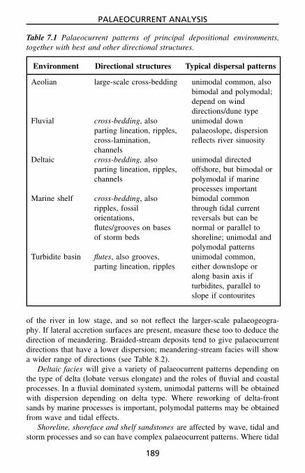
PALAEOCURRENT ANALYSIS
Table 7.1 Palaeocurrent patterns of principal depositional environments,together with best and other directional structures.
Environment Directional structures Typical dispersal patterns
Aeolian large-scale cross-bedding unimodal common, alsobimodal and polymodal;depend on winddirections/dune type
Fluvial cross-bedding, alsoparting lineation, ripples,cross-lamination,channels
unimodal downpalaeoslope, dispersionreflects river sinuosity
Deltaic cross-bedding, alsoparting lineation, ripples,channels
unimodal directedoffshore, but bimodal orpolymodal if marineprocesses important
Marine shelf cross-bedding, alsoripples, fossilorientations,flutes/grooves on basesof storm beds
bimodal commonthrough tidal currentreversals but can benormal or parallel toshoreline; unimodal andpolymodal patterns
Turbidite basin flutes, also grooves,parting lineation, ripples
unimodal common,either downslope oralong basin axis ifturbidites, parallel toslope if contourites
of the river in low stage, and so not reflect the larger-scale palaeogeogra-phy. If lateral accretion surfaces are present, measure these too to deduce thedirection of meandering. Braided-stream deposits tend to give palaeocurrentdirections that have a lower dispersion; meandering-stream facies will showa wider range of directions (see Table 8.2).
Deltaic facies will give a variety of palaeocurrent patterns depending onthe type of delta (lobate versus elongate) and the roles of fluvial and coastalprocesses. In a fluvial dominated system, unimodal patterns will be obtainedwith dispersion depending on delta type. Where reworking of delta-frontsands by marine processes is important, polymodal patterns may be obtainedfrom wave and tidal effects.
Shoreline, shoreface and shelf sandstones are affected by wave, tidal andstorm processes and so can have complex palaeocurrent patterns. Where tidal
189

PALAEOCURRENT ANALYSIS
currents dominate, bipolar patterns may be obtained, but often one tidal cur-rent direction is stronger so that the pattern is asymmetrical. Tidal currentsvary from parallel to oblique to normal to the shoreline. Storm waves and cur-rents generate cross-beds usually directed offshore, but there may be a widedispersion. Again, measure larger structures where possible (cross-beds, solestructures) rather than ripples which may represent minor reworking.
In basinal successions, palaeocurrents from turbidites are often relatedto regional basin-ward directed palaeoslopes, but having reached the basincentre, deep-sea currents may then flow along the basin axis. It is useful toknow the basin orientation and larger-scale tectonic context of the succes-sion to interpret the palaeocurrent pattern. Flutes and grooves are the beststructures to measure, since a turbidity current begins to wander once it isslowing down so that structures within and upon the bed uppersurface (cross-lamination and ripples) may not represent the main current direction. Slumpfolds are good for palaeoslope orientation. Some deepwater currents flowparallel to the contours of slopes, as in contourite deposits.
Desert sandstones can show very simple or highly complex palaeowindpatterns as measured from large-scale cross-bedding. It depends on the natureof the sand deposit – large ridges (seif draas) or sand seas (ergs), the windsystem and local topography. Some desert sandstones have unidirectionalcross-beds from the effects of persistent trade winds. Palaeowind directionsare not related to regional palaeoslope and interpretations of the palaeogeog-raphy need to be made with care.
190

8WHAT NEXT? FACIES ANALYSIS, CYCLES
AND SEQUENCES
8.1 IntroductionHaving collected all the field data from the sedimentary succession it remainsto interpret the information. Many studies of sedimentary rocks are concernedwith elucidating the conditions, environments and processes of deposition.The field data are essential to such considerations. Other studies are concernedmore with particular aspects of the rocks, such as the possibility of there beingeconomic minerals and resources present, the origin of specific structures orthe diagenetic history. Following the fieldwork, laboratory examination of therocks is necessary in many instances, not least to deduce or confirm sedimentcomposition and mineralogy.
8.2 Facies AnalysisIf the aim of the study is to deduce the depositional processes and envi-ronments then, with all the field data at hand, the facies present withinthe succession should be identified. A facies is defined by a particular setof sediment attributes: a characteristic lithology, texture, suite of sedimen-tary structures, fossil content, colour, geometry, palaeocurrent pattern, etc.A facies is produced by one or several processes operating in a deposi-tional environment, although of course the appearance of the facies can beconsiderably modified by post-depositional, diagenetic processes. Within asedimentary succession there may be many different facies present, but usu-ally the number is not great. Some facies may be repeated several or manytimes in a succession. A facies may also change vertically or laterally intoanother facies by a change in one or several of its characteristic features. Insome cases it will be possible to recognise subfacies, sediments which aresimilar to each other in many respects but which show some differences.
Facies are best referred to objectively in purely descriptive terms, using afew pertinent adjectives; examples could be cross-bedded, coarse sandstonefacies or massive pebbly mudstone facies. Facies can be numbered or referredto by letter (facies A, facies B, etc.), or a shorthand can be used whichgives an indication of what the facies is like, i.e., a lithofacies code (see
Sedimentary Rocks in the Field. Maurice E. Tucker 2003 John Wiley & Sons, Ltd ISBN: 0-470-85123-6
191

WHAT NEXT? FACIES ANALYSIS, CYCLES AND SEQUENCES
Section 2.5). However, facies are frequently referred to by their environmentof deposition, such as fluvial facies or lagoonal facies, or by their depositionalmechanism, such as turbidite sandstone facies or storm bed facies. In the fieldand during the early stages of the study, facies should be referred to only inthe descriptive sense. Interpretations in terms of process and/or environmentcan come later.
After logging and examining a succession in detail, look closely at thelog with all the sediment attributes recorded and look for beds or units withsimilar features. Take the depositional structures first since these best reflectthe depositional processes; then check the texture, lithology and fossil content.You will probably find that there is a relatively small number of distinctsediment types with similar attributes; these will be of the same facies. Nameor number them for reference.
Once the various facies have been differentiated, make a table with theirvarious features (name, code, typical thickness or thickness range, grain-size,sedimentary structures, fossils, colour, etc.). The facies can then be inter-preted by reference to published accounts of modern sediments and ancientsedimentary facies. Many textbooks contain reviews of modern depositionalenvironments, their sediments and their ancient analogues: see the Referencesand Further Reading.
Some facies are readily interpreted in terms of depositional environmentand conditions, whereas others are not environmentally diagnostic and haveto be taken in the context of adjacent facies. As an example, a fenestralpeloidal lime mudstone will almost certainly have been deposited in a tidal-flat environment, whereas a cross-bedded coarse sandstone could be fluvial,lacustrine, deltaic, shallow-marine, even deep-marine, and could have beendeposited by a variety of different processes. A number of depositional pro-cesses produce distinctive facies but can operate in several environments;for example, density currents depositing graded beds occur in lacustrine andmarine basins, shallow and deep.
Facies interpretation is often facilitated by considering the vertical faciessuccession. Where there is a conformable vertical succession of facies, withno major breaks, the facies are the products of environments which were orig-inally laterally adjacent. This concept has been appreciated since JohannesWalther expounded his Law of Facies in 1894. The vertical succession offacies is produced by the lateral migration of one environment over another(e.g., the progradation of a delta or tidal flat, the meandering of a stream).Where there are breaks in the succession, seen as sharp or erosional con-tacts between facies, then the facies succession need not reflect laterallyadjacent environments but could well be the products of widely separatedenvironments. Other environments whose sediments have been eroded couldbe represented by the break. There may have been some major change in
192

WHAT NEXT? FACIES ANALYSIS, CYCLES AND SEQUENCES
the depositional conditions at the stratigraphic break, such as a rise or fall inrelative sea level. See Section 5.3.1.1 on bedding planes.
In a sedimentary succession, you may well find that a group of faciesoccur together to form a facies association. The facies comprising an asso-ciation were generally deposited in the same broad environment, in whichthere were several different depositional processes operating, distinct suben-vironments or fluctuations in the depositional conditions. Think of a delta orsubmarine fan; there are several different processes operating there, deposit-ing different sediment types (facies), but they are all related and so form afacies association.
8.3 Facies Models and Depositional EnvironmentsFrom the study of modern depositional environments and their sedimentsand their ancient equivalents, facies models have been constructed to rep-resent and summarise the features of the depositional system and to showthe lateral and vertical relationships between facies. These models facili-tate interpretations of sedimentary rocks and permit predictions of faciesdistributions and geometries. However, it has to be remembered that faciesmodels are just snapshots of an environment, and that depositional systems aredynamic; the facies model may only relate to a particular state of sea level, forexample, or a particular climatic zone or latitude, or even a particular periodin geological time. Very generalised facies models for the major deposi-tional environments are presented later in this chapter, for the braided-stream(Fig. 8.13), meandering-stream (Fig. 8.14), deltaic (Fig. 8.15), siliciclasticshoreline (Fig. 8.16), deep-marine (Fig. 8.17), carbonate shelf (Fig. 8.18) andcarbonate ramp environments (Fig. 8.19), to be considered in association withTables 8.2–8.13, showing the features of the various facies.
From your facies data, it is possible for you to erect your own faciesmodel. Make your interpretations of the depositional environment and suben-vironments from the facies and think about their two- and three-dimensionalarrangement. Make sketches, cross-sections and block diagrams to suggestthe distribution of your facies and subfacies. Having done this, next thinkabout the major controls on deposition: sea-level change, climate, tectonics,sediment supply/production and the biota (fossil record at the time). Nextlook for cycles, rhythms and sequences in your succession of facies: seeSection 8.4.
The principal features of the main sedimentary facies are given inTables 8.2–8.13 at the end of this chapter. These are very generalised andare intended only to give a broad indication of the appearance of the variousfacies deposited in the common depositional environments. They are in noway complete, since it is not possible to summarise adequately the features ofthe various facies in a page or two, or in a simple table. Facies interpretation
193

WHAT NEXT? FACIES ANALYSIS, CYCLES AND SEQUENCES
requires much more thought and industry than just looking at a few tables.Very detailed analyses of facies can now be made, and for help you shouldrefer in the first instance to the textbooks cited in the References and FurtherReading and then to the scientific journals.
8.4 Cycle Stratigraphy and Sequence StratigraphyAs noted elsewhere in this book, sedimentary rocks are commonly arrangedinto distinct units which are repeated several or many times in a succession.
Table 8.1 Features to describe with metre-scale cyclic sediments andparasequences.
A: Cycle/parasequence boundaries1. Look for evidence of exposure at top of cycle (e.g., palaeokarsts,
potholes, palaeosoils, rootlets, coal, fenestrae, supratidal evaporites,vugs).
2. If no exposure, look for evidence of a break in sedimentation (e.g.,intense bioturbation, hardground with encrusting fossils and borings).
3. Look for evidence of flooding at base of cycle (e.g., shale,phosphorite, glauconite, lag deposit, reworked pebbles and fossils).
B: Internal structure of cycles/parasequences1. Look for upward changes in lithofacies (e.g., limestone passing up
into dolomite or gypsum, lime mudstone passing up into grainstone(or vice versa), mudrock passing up into sandstone).
2. Look for upward changes in grain-size (coarsening-upwards or fining-upwards).
3. Look for upward changes in bed thickness (thickening-upwards orthinning-upwards).
C: Stacking patterns of cycles/parasequences1. Look at thickness of successive cycles; is each cycle thicker or thinner
upwards?2. Look at degree of exposure at tops of cycles: is it increasing or
decreasing upwards through the stack of cycles?3. Look at the facies within the parasequence stack: is there a long-term
trend of shallowing or deepening? For example, are the cycles moreintertidal or subtidal up the stack?
4. Look for repeated packaging of the cycles into sets: e.g., are theyorganised into several or many packages of 3–8 cycles?
5. Make a Fischer plot to show cycle thickness variation through thesuccession versus the average cycle thickness.
194

WHAT NEXT? FACIES ANALYSIS, CYCLES AND SEQUENCES
Thin repeated units, on a scale of 1–10 metres, are usually referred to assedimentary cycles, or in sequence stratigraphy terminology, parasequences(see Section 2.10.2). They were deposited over timespans of a few tens tohundreds of thousands of years. Parasequences are the building blocks ofsequences which are generally on the scale of many tens to hundreds ofmetres in thickness, deposited over a timespan of 0.5 to 3 million years(see Section 2.10.2). Table 8.1 gives the points to note when recordingcyclic sediments.
8.4.1 Sedimentary cycle motifsMetre-scale cycles vary considerably in composition and facies depending onthe depositional environment. The majority of shallow-water, shoreline, shelfand platform cycles show a shallowing-upward trend, recorded by changesin lithologies, composition, grain-size and microfacies.
Some cycles are alternations of lithologies, e.g., mudrock–limestone indeeper-water basinal successions (Fig. 8.1 and 8.2), limestone–gypsum orlimestone–dolomite in carbonate platform successions (Fig. 8.5), mudrock–sandstone in shallow- and deep-marine siliciclastic successions (Fig. 8.3), andsandstone–mudrock in meandering-stream strata (see Fig. 8.14).
Figure 8.1 Alternations of pelagic limestone and hemipelagic mudstone. Lookfor systematic upward changes in bed thickness. 20 metres of strata exposed.Cretaceous, French Alps.
195

WHAT NEXT? FACIES ANALYSIS, CYCLES AND SEQUENCES
Figure 8.2 Packaging of pelagic limestone beds into thicker units, throughchanges in clay content. 10 metres of strata exposed. Cretaceous, SpanishPyrenees.
Other cycles show systematic upward changes within the cycle, e.g., acoarsening-up of grain-size, as in deltaic (see Fig. 8.15) and submarine fan-lobe mudrock to sandstone cycles (Figs 8.3 and 8.17), or deeper-water limemudstone to shallower-water grainstone cycles of carbonate ramps (Fig. 8.4),or a fining-up of grain-size as in meandering stream sandstone to mudrockcycles (see Fig. 8.14), or high-energy shallow-water grainstone to tidal-flatfenestral lime mudstone of carbonate platform interiors (Fig. 8.4).
There may be systematic upward changes in the thickness of beds withincycles (thinning-up or thickening-up, as in Figs 8.3 and 8.5; see Section 8.4.3).
The presence of cycles within a succession can usually be seen in thefield by close observation of the facies. In some cases the cycles will createsteps or slope changes in the topography, as a result of some beds beingeroded out more easily. Rarely, the cyclicity is only revealed after a detailedgraphic log has been made or after some statistical tests have been applied(see textbooks cited in the References and Further Reading).
196

WHAT NEXT? FACIES ANALYSIS, CYCLES AND SEQUENCES
Figure 8.3 Packaging of deepwater sandstones (composition is greywacke).Turbidites arranged into coarsening-upward units 2–5 m in thicknessconsisting of some five to ten individual event beds, each unit separated by0.5–1 m of mudrock from the next. In some turbidite packages there is asuggestion of bed thickness increasing upward. Younging direction to the right.Cretaceous, California.
8.4.2 Cycle boundariesExamine the boundaries between cycles carefully; distinct horizons mayoccur here. In many cases the top of a cycle is an exposure horizon, e.g., apalaeosoil (calcrete, seatearth or rootlet bed), palaeokarstic surface, desiccatedmicrobial laminites or fenestral lime mudstones. The tops of some cycleswere not subaerially exposed, but show evidence of shallowing and a pause indeposition in the form of intense bioturbation or a hardground with encrustingand boring organisms. See Fig. 5.5 for the variety of bedding surfaces, whichare often cycle boundaries.
The base of a cycle is usually a flooding surface. Thus there may be athin conglomerate (a basal lag) of material reworked from the top of theunderlying cycle and evidence of erosion (a sharp, scoured surface), and/ora muddy bed reflecting the deeper-water conditions of the transgressioninitiating the new cycle. Across a flooding surface there is a deepeningof facies.
197

WHAT NEXT? FACIES ANALYSIS, CYCLES AND SEQUENCES
expo
sure
sur
face
perit
idal
dolo
mite
subt
idal
limes
tone
perit
idal
lime
mud
ston
e
oo-b
io-
grai
nsto
ne
PE
RIT
IDA
L C
YC
LES
stor
m-b
ed
limes
tone
s
hard
grou
nd
oo-b
io-
grai
nsto
ne
ribbo
n ro
cks
-sto
rm b
eds
SU
BT
IDA
L C
YC
LES
Fig
ure
8.4
The
spec
trum
ofsh
allo
win
g-up
war
dca
rbon
ate
unit
s(c
ycle
s/pa
rase
quen
ces)
;thi
ckne
sses
are
typi
call
y0.
75–
2m
,bu
tm
ayre
ach
mor
eth
an10
m.
198

WHAT NEXT? FACIES ANALYSIS, CYCLES AND SEQUENCES
8.4.3 Cycle stacking patterns and cyclostratigraphy
Figure 8.5 Shallowing-upwardcarbonate cycles (arrows markcycle boundaries) with thin, whitedolomite bed at top of each cycle.Notice that there is an upwarddecrease in cycle thickness. Heightof cliff 20 m. Cambrian, N.W.Scotland.
If a succession is cyclic, there willprobably be some systematic changesin the nature of the cycles up throughthe succession. It is important todocument these as they will reflectthe longer-term controls on deposition,primarily changes in accommodationspace through time, and factors relatedto these. In many cases there aresystematic variations in cycle thicknessthrough a succession, cycles graduallyincreasing or decreasing in thicknessupwards (Figs 8.5 and 8.6). In someinstances, cycles are arranged intopackages of three to eight cycles, toform a cycle set, with the thickness(or grain-size) of each successive cycledecreasing or increasing upwards (e.g.,Fig. 8.7). In fact, there can be awhole hierarchy of cycles–cycle, cycleset, mesocycle set, megacycle set – inthe succession.
Measure up the cycle thicknessthrough a succession and look forany patterns (i.e., thinning upwards orthickening upwards). A Fischer plot isa useful way of presenting the data, especially for peritidal carbonate cycleswhich shallow up to sea level. In a Fischer plot, the thickness of eachsuccessive cycle is plotted relative to the average cycle thickness (Fig. 8.8).The pattern is interpreted to reflect the long-term change in accommodationspace and relative sea level through time. It is dangerous, however, to assumethat each cycle represents the same length of time without more detailedstudy. Statistical tests can be applied to the thickness data of cycles to confirmwhether the thickness patterns are random or not, and to help deduce theorigin of the cyclicity (see appropriate textbooks).
There may also be systematic changes in the internal structure of the cyclesthemselves and of the nature of the cycle boundaries. Look for variations inthe facies of successive cycles (e.g., upward increasing/decreasing proportionsof subtidal to intertidal facies). The degree of subaerial exposure at cycle topsmay also increase or decrease up the succession. If the cycles are developedover a large area, then look for lateral changes in the facies of individual
199

WHAT NEXT? FACIES ANALYSIS, CYCLES AND SEQUENCES
small-scalesea-level changesgive cycles
thin cyclestidal-flat dominated
thickening-upcycles
thick cyclessubtidal-dominated
thinning-upcycles
falling
exposuresurface
subtidal facies
intertidal facies
relativesea-level
rising
LST
TST
HSTFSST
Figure 8.6 The stacking patterns of parasequences within a sequence.Each individual metre-scale cycle is produced by one high-frequencyrelative sea-level cycle, and the longer-term thickness pattern reflects thelower-frequency, longer-term change in accommodation space. The stackingpatterns define the systems tracts of the sequence, as shown.
cycles if they can be correlated, or of the package of cycles as a whole ifseparate localities are involved.
The close study of metre-scale cycles, cyclostratigraphy, can help in thecorrelation of successions. In some cases, one specific cycle will show someparticular features, such as a fossil band or well-developed exposure surfacewith a special colour, which will enable correlations between outcrops. Onceyou get to know your strata and their characteristic features, you can then lookfor these in other outcrops; it is surprising how laterally extensive are beddingplanes, facies, shell beds, etc. In a more general way, the broad, upwardchanges in facies/thickness/grain-size (etc.) through a cyclic succession canalso be used for correlation.
The origin of these metre-scale cycles or parasequences is of great interestand useful information can be obtained by making the observations sug-gested here. Autocyclic mechanisms (sedimentary processes such as tidal-flatprogradation and lateral migration of meandering streams) give rise to cyclicsediments, as do allocyclic mechanisms such as tectonic processes (e.g., jerkysubsidence and in-plane stress changes) and sea-level change, such as throughorbital forcing and solar insolation variations, and glacioeustasy (see appro-priate textbooks).
The nature of sedimentary cycles does vary through the geologicalrecord, in response to major periods of tectonic activity and tectonic
200

WHAT NEXT? FACIES ANALYSIS, CYCLES AND SEQUENCES
mud
m
sets cycles graphiclog
grain-sizetrends
30
0
5
10
15
20
25
sand
Figure 8.7 An example of metre-scale cycles and their stacking pattern; asuccession consists of coarsening-upward units (thin arrows show the cycles),and they group into packages (sets) based on the increasing grain-size andthickness.
quiescence, and to the longer-term variations in global climate, namelyperiods of icehouse (late Precambrian/Cambrian, Permo-Carboniferous andlate Tertiary–Quaternary) and greenhouse (mid-Palaeozoic and Triassicthrough early Tertiary). The amplitudes of rapid sea-level changes (over tensto thousands of years) were much higher in the icehouse periods than in thegreenhouse periods.
201

WHAT NEXT? FACIES ANALYSIS, CYCLES AND SEQUENCES
cum
ulat
ive
devi
atio
n of
cyc
leth
ickn
ess
from
ave
rage
cyc
leth
ickn
ess
3rd-order relative sea-level curve/path of change of accommodation space
43210
4
2
0
−2
−4
cycle number
parasequencethickness
Fischer Plotmetres
Figure 8.8 A Fischer plot. From the total thickness of the succession calcu-late the average thickness of a cycle. Plot the average cycle thickness (in thisexample 2 metres) as a diagonal line and then the thickness of each succes-sive cycle as a vertical line. The horizontal scale is the cycle number throughtime. The vertical scale shows the deviation of cycle thickness through thesuccession from the average cycle thickness. Do not assume that each cyclewas deposited over the same length of time. For cycles that shallow up to sealevel, the trend of the cycle thickness through time may reflect the longer-termchange in relative sea level and accommodation space. See appropriate booksand papers for further information.
8.4.4 Cycle stacking and sequence stratigraphyIn terms of sequence stratigraphy, introduced in Section 2.8 with terms definedin Table 2.6, the stacking pattern of the parasequences within a successionof metre-scale cycles determines the systems tract to which they belong aspart of the sequence. For example, thickening-upward, subtidal-dominatedparasequences capped by weak (or no) exposure horizons typify the trans-gressive to highstand systems tract, whereas thinning-upward, inter/supra-tidalfacies-dominated parasequences capped by well-developed emergence hori-zons are typical of late highstand, falling stage and lowstand systems tracts(see Fig. 8.6).
Within many successions dominated by metre-scale cycles (parase-quences), there is no clear sequence boundary but there is a sequence bound-ary zone (SBZ) where cycles tend to be thinner, more intertidal/subaerial
202

WHAT NEXT? FACIES ANALYSIS, CYCLES AND SEQUENCES
facies are present and there is more evidence for exposure. In the same way,there may not be a specific maximum flooding surface, but there will bea zone (MFZ) within the cyclic succession where cycles are thicker anddominantly subtidal with little evidence of exposure.
Table 8.1 gives the main features to look for when describing parase-quences and cyclic sediments.
8.4.5 Sequence stratigraphy in the fieldIt is very popular these days to divide a succession into sequences (seeSection 2.10.2). However, to do this, a lot of biostratigraphical and sedimen-tological information is required from the sedimentary basin as a whole.Observations from a single locality can often be interpreted in terms ofsequence stratigraphy and then the ideas confirmed or modified after theexamination of other localities in the region.
Sequence stratigraphy divides a succession on the basis of key surfacesinto systems tracts. The sediments of the various systems tracts usually showparticular facies successions (e.g., deepening-up in the TST, shallowing-upin the HST), or if the succession is composed of small-scale cycles (parase-quences), then the systems tracts are defined on the stacking patterns andfacies of the parasequences: see Section 8.4.4.
Some of the key surfaces have distinctive sedimentological features whichcan be observed in the field. These are noted here, but again remember that itis necessary to consider the succession on a larger scale, taking into accountthe regional sedimentology and biostratigraphy and the relationships betweensedimentary units (onlap, downlap, etc.: see Section 5.7) to be sure that yourinterpretations from one locality are realistic.
In sequence stratigraphy, the key surfaces are the sequence boundary,the transgressive surface (base of the TST) and the maximum floodingsurface (separating the TST from the HST). Also important is the condensedsection, the more distal (basinward) equivalent of the maximum floodingsurface which normally includes some of the upper TST and lower HST (seeSection 2.10.2).
8.4.5.1 Sequence boundary (sb)Although very variable in nature, the ‘classic’ sequence boundary is usuallya distinctive surface that shows evidence of significant erosion and extendedsubaerial exposure (e.g. a palaeokarst or palaeosoil). There is usually a bios-tratigraphic gap, and underlying strata may be truncated by the unconformity.There will usually be a significant and abrupt facies change across the bound-ary; in many cases it will be a change from marine facies (HST) belowto non-marine facies (FSST/LST) above the boundary, or in more basinallocations from deeper-water, finer-grained facies of the highstand (below) to
203

WHAT NEXT? FACIES ANALYSIS, CYCLES AND SEQUENCES
shallower-water, coarser-grained facies of the falling stage/lowstand (above),both indicating a downward (basinward) facies shift as a result of the rela-tive sea-level fall which created the sequence boundary. In more proximal(landward) areas, however, deeper-water facies of the TST will overlie thesequence boundary if, as is often the case, no falling stage/lowstand sedimentswere deposited there. The sequence boundary would then coincide with thetransgressive surface. Basinwards the sequence boundary will pass into a con-formity which will show little or no evidence of erosion. Sequence boundarieswill have regional, basin-wide extent, and may possibly be correlatable withsequence boundaries in other basins.
Associated with sequence boundaries are often incised valley fills (IVF).These linear, major valleys are cut during the relative sea-level fall (fallingstage) and filled during the lowstand and subsequent TST. IVFs have sharpbasal surfaces (the sb), cutting down several to tens of metres; coarse fluvialclastics will fill the lower part, passing up into finer estuarine and marinesandstones. Major soil horizons are often laterally equivalent, formed on theinterfluves.
A further, different type of sequence boundary is recognised in carbon-ate strata, the drowning unconformity. This is again a prominent horizon,where deepwater facies overlie shallow-water limestones. The surface of thecarbonate platform may been exposed first, before the drowning, so that apalaeokarst is present. Drowning surfaces may be mineralised or encrustedwith phosphate.
8.4.5.2 Transgressive surface (ts)This surface will usually show a major facies change from shallower-wateror subaerial facies below to deeper-water facies above (which may be wide-spread), reflecting the increased water depth and relative rise in sea level.The transgressive surface (also called the top lowstand surface or ravinementsurface) is the first significant marine flooding surface across a shelf. A lagdeposit (pebble bed, bone bed, concentration of fossils) may occur upon thesurface, which is usually sharp, as a result of erosion during the transgression.New fossil species may occur, and overall the sediments above the ts willgenerally deepen upwards.
8.4.5.3 Maximum flooding surface (mfs)This surface should occur within the deepest-water or most marine facies ofthe sequence, since it represents the time of maximum transgression. It isgenerally the most significant flooding surface of the succession. It may notbe an actual bedding plane but occur within, say, an organic-rich mudrock afew metres thick, with shallower-water facies below (of the TST) and above
204
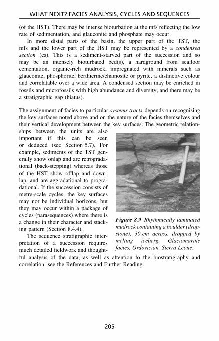
WHAT NEXT? FACIES ANALYSIS, CYCLES AND SEQUENCES
(of the HST). There may be intense bioturbation at the mfs reflecting the lowrate of sedimentation, and glauconite and phosphate may occur.
In more distal parts of the basin, the upper part of the TST, themfs and the lower part of the HST may be represented by a condensedsection (cs). This is a sediment-starved part of the succession and somay be an intensely bioturbated bed(s), a hardground from seafloorcementation, organic-rich mudrock, impregnated with minerals such asglauconite, phosphorite, berthierine/chamosite or pyrite, a distinctive colourand correlatable over a wide area. A condensed section may be enriched infossils and microfossils with high abundance and diversity, and there may bea stratigraphic gap (hiatus).
The assignment of facies to particular systems tracts depends on recognisingthe key surfaces noted above and on the nature of the facies themselves andtheir vertical development between the key surfaces. The geometric relation-
Figure 8.9 Rhythmically laminatedmudrock containing a boulder (drop-stone), 30 cm across, dropped bymelting iceberg. Glaciomarinefacies, Ordovician, Sierra Leone.
ships between the units are alsoimportant if this can be seenor deduced (see Section 5.7). Forexample, sediments of the TST gen-erally show onlap and are retrograda-tional (back-stepping) whereas thoseof the HST show offlap and down-lap, and are aggradational to progra-dational. If the succession consists ofmetre-scale cycles, the key surfacesmay not be individual horizons, butthey may occur within a package ofcycles (parasequences) where there isa change in their character and stack-ing pattern (Section 8.4.4).
The sequence stratigraphic inter-pretation of a succession requiresmuch detailed fieldwork and thought-ful analysis of the data, as well as attention to the biostratigraphy andcorrelation: see the References and Further Reading.
205

WHAT NEXT? FACIES ANALYSIS, CYCLES AND SEQUENCES
Debris-flow depositsHigh-density turbidity
current depositsLow-density turbidity
current deposits
TbTc
Td
Te
TaTb
TcTd
Te
Matrix-supported
(a)
Clast-supported
(b) (c) (d) (e) (f)
Figure 8.10 The range of deepwater sediment gravity-flow deposits: debritesand turbidites. These beds range from a few centimetres to a metre or morein thickness.
Tb
TaTc
Td Te
coarse-grainedturbidite medium-grained
turbiditefine-grained
turbidite
sediment transport
Figure 8.11 Downcurrent changes in turbidites.
Figure 8.12 A turbidite bed showingABC divisions: a lower coarse massivedivision (A), overlain by a finer-grainedparallel-laminated division (B), andthen the upper part consisting of cross-laminae with a convolution at the top (Cdivision). This turbidite is a bioclasticlimestone. Devonian, S.W. England.
206
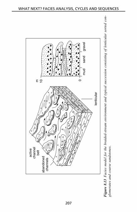
WHAT NEXT? FACIES ANALYSIS, CYCLES AND SEQUENCES
mud
010m
lent
icul
ar
sand
grav
el
aban
done
dch
anne
ls
activ
ech
anne
lbe
lt
Fig
ure
8.13
Fac
ies
mod
elfo
rth
ebr
aide
d-st
ream
envi
ronm
ent
and
typi
cal
succ
essi
onco
nsis
ting
ofle
ntic
ular
sort
edco
n-gl
omer
ates
and
coar
sesa
ndst
ones
.
207

WHAT NEXT? FACIES ANALYSIS, CYCLES AND SEQUENCES
msa
nd
coal
chan
nel s
and
late
ral
accr
etio
n of
poin
t bar
river
chan
nel
crev
asse
sand
s
poin
t bar
san
d
chan
nel s
and
flood
pla
in m
ud
poin
t bar
leve
e
flood
plai
n
crev
asse
spla
y
Fig
ure
8.14
Fac
ies
mod
elfo
rth
em
eand
erin
g-st
ream
envi
ronm
ent
and
typi
cal
succ
essi
onco
nsis
ting
ofa
finin
g-up
war
dsa
ndst
one
unit
capp
edby
mud
rock
prod
uced
byla
tera
lm
igra
tion
ofth
est
ream
.Su
chun
its
vary
inth
ickn
ess
from
afe
wm
etre
sto
afe
wte
nsof
met
res.
Lat
eral
accr
etio
nsu
rfac
esm
ayoc
cur
wit
hin
the
sand
ston
em
embe
r.
208

WHAT NEXT? FACIES ANALYSIS, CYCLES AND SEQUENCES
∗ ba
y
chan
nel (
dc)
mar
sh
mbs
dbm
s
dcs
dbm
s
pdm
bfm
pdm
bfm
mud
sand
mud
sand
(a)
(b)
mou
thba
r (m
b) dist
alba
r (d
b) prod
elta
(pd
)
basi
nflo
or (
bf)
Fig
ure
8.15
Fac
ies
mod
elfo
rth
em
arin
ede
ltai
cen
viro
nmen
tan
dtw
oty
pica
lsu
cces
sion
s:(a
)co
arse
ning
-upw
ard
(c.u
.)un
itpr
oduc
edby
delt
apr
ogra
dati
ondu
ring
ase
a-le
vel
stil
lsta
ndan
dca
pped
byco
al;
(b)
ac.
u.un
itcu
tby
adi
stri
buta
rych
anne
lsa
ndst
one.
Thi
ckne
sses
rang
efr
om10
to30
mor
mor
e.T
here
can
bem
uch
vari
atio
nin
thes
eun
its,
part
icul
arly
tow
ards
the
top
ifin
terd
istr
ibut
ary
bays
are
deve
lope
d.m
–m
ud,m
s–m
uddy
sand
,s–
sand
.
209

WHAT NEXT? FACIES ANALYSIS, CYCLES AND SEQUENCES
Was
hove
rfa
nB
acks
hore
dune
sB
each
/F
ores
hore
dune
san
d
fore
shor
e sa
nd
shor
efac
e sa
nd
offs
hore
san
ds
and
mud
s
offs
hore
mud
Sho
re-
face
Offs
hore
Ebb
tidal
delta
Flo
odtid
alde
ltaLa
goon
Tid
al c
hann
el
offs
hore
mud
shor
efac
esa
nds
beac
hsa
nds
dune
sand
s
Tid
al fl
ats
Mar
sh
fmc
mud
san
d
Fig
ure
8.16
Fac
ies
mod
elfo
rm
arin
esh
orel
ine
envi
ronm
ent
and
the
typi
cal
coar
seni
ng-u
pwar
dsu
cces
sion
deve
lope
dth
roug
hpr
ogra
dati
onof
abe
ach/
barr
ier
shor
elin
edu
ring
ase
a-le
vel
stil
lsta
nd.T
ypic
alth
ickn
ess
10m
orm
ore.
210
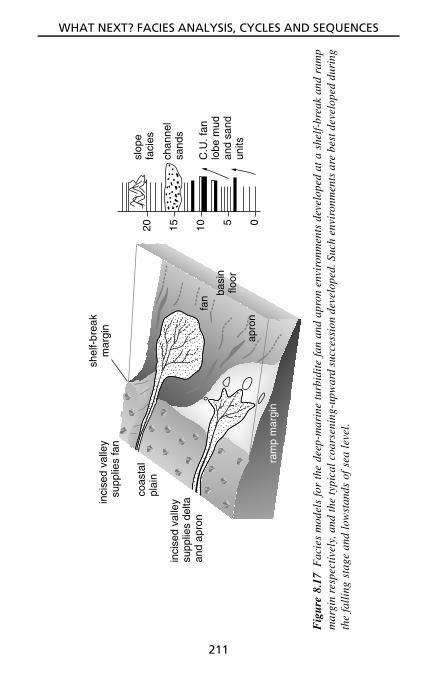
WHAT NEXT? FACIES ANALYSIS, CYCLES AND SEQUENCES
shel
f-br
eak
mar
gin
inci
sed
valle
ysu
pplie
s fa
n
inci
sed
valle
ysu
pplie
s de
ltaan
d ap
ron
coas
tal
plai
n
ram
p m
argi
n
fan
apro
n
basi
nflo
or
05101520sl
ope
faci
es
chan
nel
sand
s
C.U
. fan
lobe
mud
and
sand
units
Fig
ure
8.17
Fac
ies
mod
els
for
the
deep
-mar
ine
turb
idit
efa
nan
dap
ron
envi
ronm
ents
deve
lope
dat
ash
elf-
brea
kan
dra
mp
mar
gin
resp
ectiv
ely,
and
the
typi
calc
oars
enin
g-up
war
dsu
cces
sion
deve
lope
d.Su
chen
viro
nmen
tsar
ebe
stde
velo
ped
duri
ngth
efa
llin
gst
age
and
low
stan
dsof
sea
leve
l.
211

WHAT NEXT? FACIES ANALYSIS, CYCLES AND SEQUENCES
CARBONATE RIMMED SHELF slope basin
subaerial
mudstones
supratidalcarbonates
protected
wackestones−mudstones
lagoonal and tidal flatcarbonates
maximumwave action
boundstones/grainstones
reefs andcarbonatesand bodies
below fairweatherwave-base
grain/rud/float/wackestones
resedimentedcarbonates
mudstones
shales/pelagiclimestones
sea level
Figure 8.18 Facies model for the carbonate shelf environment.
CARBONATE RAMP
inner ramp mid ramp outer ramp
protected/subaerial
wackestones−mudstones
lagoonal−tidal flat−supratidalcarbonates, sabkhaevaporites palaeosoils,palaeokarsts
below fairweatherwave-base
grain/rud/float/wackestones
thin-beddedlimestones, stormdeposits ± mudmounds
below stormwave-base
mudstones
shales/pelagiclimestones
wave-dominated
grainstones
beach-barrier/strandplain/sandshoals, patch reefs
sea-level
fwwb
swb
Figure 8.19 Facies model for the carbonate ramp environment.
212

WHAT NEXT? FACIES ANALYSIS, CYCLES AND SEQUENCES
Table 8.2 General features of fluvial facies
Deposition: complex; alluvial systems include meandering streams withwell-developed floodplains (see Fig. 8.14), braided streams (see Fig. 8.13)and alluvial fans. In the first, lateral migration of channels is character-istic, with muddy overbank sedimentation and sandy crevasse splays onfloodplains. Channel processes dominate in braided streams, which maybe gravel- or sand-dominated, and stream and sheet floods and debrisflows occur on alluvial fans.Lithologies : from conglomerates through sandstones to mudrocks; thinintraformational conglomerates common; many sandstones are lithic orarkosic, compositionally immature to mature.
Textures : many stream-deposited conglomerates have a pebble-supportfabric with imbrication; debris-flow conglomerates are matrix supported;most fluvial sandstones consist of angular to subrounded grains, withpoor to moderate sorting, i.e., texturally immature to mature; some fluvialsandstones and mudrocks are red.Structures : fluvial sandstones show tabular and trough cross-bedding, flatbedding plus parting lineation, low-angle cross-beds (lateral accretion sur-faces), channels and scoured surfaces; finer sandstones show ripples andcross-lamination; stream-deposited conglomerates are lenticular with flatbedding and crude cross-bedding; floodplain mudrocks are usually mas-sive, possibly with rootlets and calcareous nodules (calcrete); they maycontain thin, persistent sharp-based sandstones deposited from crevassesplays and floods.
Fossils : plants dominate (fragments or in situ), also fish bones and scales,freshwater molluscs, vertebrate tracks, some dwelling burrows.
Palaeocurrents : unidirectional, but dispersion depends on stream type:braided-stream sandstones have lower dispersion than meandering-streamsandstones.Geometry : sand bodies vary from ribbons to belts to fans.
Facies successions and cycles : depend on type of alluvial system: allu-vial fan strata may show an overall coarsening-up or fining-up dependingon climatic/tectonic changes; meandering streams produce fining-upwardcross-bedded sandstone units up to several metres thick with lateral accre-tion surfaces, interbedded with mudrocks which may contain calcretesand thin persistent sandstones deposited by crevasse splays and floods(Fig. 8.14); sandy braided streams produce lenticular and multi-storeycross-bedded sandstones with few mudrock interbeds (Fig. 8.13).
Relevant sections : 3.2, 3.3, 3.4, 5.2, 5.3.
Relevant figures : 4.7, 5.3–5.19, 5.32, 5.61–5.63, 8.13–8.14.
213

WHAT NEXT? FACIES ANALYSIS, CYCLES AND SEQUENCES
Table 8.3 General features of aeolian facies.
Deposition: wind-blown sand is typical of deserts but also occurs alongmarine shorelines.Lithology : clean (matrix-free) quartz-rich sandstones; no mica.
Textures : well-sorted, well-rounded sand grains (‘millet-seed’); possiblywith frosted (dull) appearance; sandstones commonly stained red throughhematite; pebbles may be wind-faceted.
Structures : dominantly large-scale cross-bedding (set heights severalmetres to several tens of metres); cross-bed dips up to 35◦; reactivationsurfaces and master bounding surfaces; grain-fall and grain-flow laminae.
Fossils : rare; possibly vertebrate footprints and bones, and rootlets.
Sand-body geometry : laterally extensive sheets if sand seas (ergs), andmore elongate ridge-like geometries if seif draas.
Facies associations : water-lain sandstones and conglomerates (fluvial/flash-flood) may be associated; also playa-lake mudrocks and evaporitesand arid-zone soils (calcretes).
Relevant sections : 3.2.1, 4.5, 5.3.2.3, 5.3.3.11.
Relevant figures : 3.4, 5.31.
214

WHAT NEXT? FACIES ANALYSIS, CYCLES AND SEQUENCES
Table 8.4 General features of lacustrine facies
Deposition: in lakes which vary in size, shape, salinity and depth. Wavesand storm currents important in shallow water; turbidity currents and riverunderflows in deeper water. Biochemical and chemical precipitation com-mon. Strong climatic control on lake sedimentation.
Lake types : permanent, perennial and ephemeral; hypersaline and fresh-water; stratified and non-stratified; bench and ramp margins; carbonate,evaporitic and siliciclastic lakes.
Lithologies : diverse, including conglomerates through sandstones tomudrocks, limestones (oolitic, micritic, bioclastic, microbial), marls,evaporites, cherts, oil shales and coals.
Structures : wave-formed ripples, desiccation cracks, rainspots and stroma-tolites common in lake shoreline sediments; spring deposits of calcareoustufa and travertine; rhythmic lamination, possibly with syneresis cracks,typical of deeper-water lake deposits, together with interbedded gradedsandstones of turbidity current origin.
Fossils : non-marine invertebrates (especially bivalves and gastropods);vertebrates (footprints and bones); plants, especially algae.
Facies successions and cycles : reflect changes in water level through cli-matic or tectonic events; shallowing-upward cycles common, capped byexposure and/or pedogenic horizons.
Facies associations : fluvial and aeolian sediments commonly associated;soil horizons may occur within lacustrine sequences; mottled and mar-morised palustrine mudrocks and limestones.
Relevant sections : 5.3, 5.5.6.2
Relevant figures : 5.8, 5.9, 5.20, 5.36–5.38, 5.61–5.63.
215

WHAT NEXT? FACIES ANALYSIS, CYCLES AND SEQUENCES
Table 8.5 General features of pedogenic facies.
Deposition: pedogenesis can take place at emergence horizons, on aban-donment surfaces, at unconformities and cycle and sequence boundaries.
Lithologies : limestone (calcrete/caliche), dolomite (dolocrete), sandstone(seatearth, ganister, silcrete), mudrock (fireclay, seatearth), karstic brec-cias.Textures : mostly fine-grained, also pisolitic, peloidal, mottled, marmorised.
Structures : massive, laminated, nodular, intraclastic, rhizocretions, sheetcracks, tepees, palaeokarstic surfaces, potholes/vugs.
Fossils : plants common, especially rootlets; others rare: non-marine ver-tebrates and invertebrates.Geometry : generally sheet-like.
Facies sequences : pedogenic facies typically occur at the top of cycles,e.g., meandering-stream fining-upward cycles, deltaic and shorelinecoarsening-upward cycles and carbonate shallowing-upward cycles, andwithin lacustrine strata, generating the palustrine facies.
Relevant sections : 4.8, 5.4.1.5, 5.4.2, 5.5.6.2, 5.6.4.
Relevant figures : 5.61–5.63.
216

WHAT NEXT? FACIES ANALYSIS, CYCLES AND SEQUENCES
Table 8.6 General features of ancient (pre-Quaternary) glacial facies.
Deposition: takes place in a wide variety of environments: beneath glaciersof various types, in glacial lakes, on glacial outwash plains and glacioma-rine shelves and basins, and by a variety of processes including movingand melting glaciers, meltwater streams, meltwater density currents, debrisflows, and icebergs. See Table 8.7 for Quaternary till types.
Continental glacial environments: grounded-ice glaciofluvial, glaciolacus-trine – proglacial and periglacial lakes, cold-climate periglacial facies.
Glacial marine environments : proximal/shoreline, shelf, deepwater facies.
Lithologies : variety of conglomerates – polymictic muddy to pebbly con-glomerates (diamictites and mixtites, which may be tillites), sandstones,muddy sediments with dispersed clasts (dropstones).
Textures : poorly sorted, matrix-supported conglomerates (diamic-tites) to better sorted clast-supported conglomerates where rework-ing/resedimentation has taken place; angular clasts possibly with striationsand facets, and elongate clasts possibly showing preferred orientation.
Structures : diamictites/tillites, generally massive but some layering mayoccur; rhythmically laminated (‘varved’) muddy sediments common (pos-sibly with dropstones); fluvioglacial sandstones show cross-bedding, cross-lamination, flat bedding, scours and channels. Striated pavements beneathcontinental tillites.Fossils : generally absent (or derived), except in glaciomarine sediments.
Geometry : tillites lenticular to laterally extensive.
Facies sequences and associations : usually no repeated sequences butapparently random succession of tillites, fluvioglacial and more glacio-lacustrine sediments; however, alternating periods of glaciation (tillites)and deglaciation (shallow-marine sandstones) may give cycles; debritesand turbidites associated with glaciomarine facies.
Relevant section: 4.6.Relevant figures : 4.9, 8.9.
217

WHAT NEXT? FACIES ANALYSIS, CYCLES AND SEQUENCES
Tabl
e8.
7M
ain
type
sof
glac
ial
till
,as
reco
gnis
edin
Qua
tern
ary
succ
essi
ons,
and
the
feat
ures
ofth
eir
depo
sits
.
Till
type
Cla
stfa
bric
Cla
stsh
ape
Dep
osit
Stru
ctur
es
Supr
agla
cial
till
wea
k,ch
aotic
gene
rally
angu
lar
and
fres
h
diam
icto
nw
ithst
ratifi
edun
its,
rem
obili
sed
tode
brite
s
defo
rmat
ion
stru
ctur
esco
mm
on,
faul
ts,
slum
ps
Subg
laci
altil
l:L
odge
men
ttil
lst
rong
fabr
icin
ice-
flow
dire
ctio
n
gene
rally
roun
ded
and
abra
ded
usua
llyho
mog
eneo
usdi
amic
ton,
shar
pba
se,
exte
nsiv
e
stru
ctur
eles
s,jo
ints
,sh
ears
Subg
laci
altil
l:D
efor
min
gbe
dtil
lm
ediu
mge
nera
llyro
unde
dho
mog
eneo
usdi
amic
ton
fold
s
Subg
laci
altil
l:M
elt-
out
till
wea
kto
stro
ngge
nera
llyro
unde
dho
mog
eneo
usan
dst
ratifi
eddi
amic
ton
stru
ctur
eles
s,so
me
bedd
ing,
may
bede
form
ed
Flow
till:
the
abov
etil
lsaf
fect
edby
grav
ity-fl
ows
wea
kto
stro
ngan
ysh
ape
stra
tified
diam
icto
nm
assi
veto
grad
edbe
ddin
g,fo
lds
218

WHAT NEXT? FACIES ANALYSIS, CYCLES AND SEQUENCES
Table 8.8 General features of deltaic facies.
Deposition: complex; there are several types of delta (especially lobateand elongate), and many deltaic subenvironments (distributary channelsand levees, swamps and lakes, mouth and distal bars, interdistributary baysand prodelta slope). Many ancient deltas were river dominated but rework-ing and redistribution of sediment by marine processes was important.
Lithologies : mainly sandstones (compositionally immature to mature,commonly lithic) through muddy sandstones, sandy mudrocks tomudrocks; also coal seams and sideritic ironstones.
Textures : not diagnostic (texturally immature to mature): average sortingand rounding of sand grains.
Structures : cross-bedding of various types in the sandstones; flat-beddingand channels common. Finer sediments show flaser and wavy bedding andare heterolithic. Some sediments contain rootlets (seatearths, ganisters);nodules of siderite. Bioturbation and trace fossils common.Fossils : marine fossils in some mudrocks and sandstones, others withnon-marine fossils, especially bivalves. Plants common.
Palaeocurrents : mainly directed offshore but may be shore-parallel oronshore if much marine reworking with waves and tides.
Geometry : sand bodies vary from ribbons to sheets depending on deltatype.
Facies successions and cycles : typically consist of coarsening-upward unit(mudrock to sandstone), through delta progradation, capped by a seatearthand coal (Fig. 8.15); there are many variations, however, particularly atthe top of such units.
Relevant sections : 3.2, 3.4, 5.2, 5.3.
Relevant figures : 5.3–5.26, 5.32, 8.15.
219
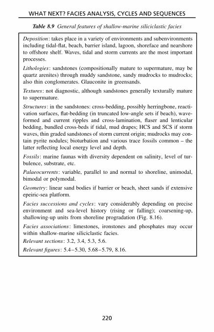
WHAT NEXT? FACIES ANALYSIS, CYCLES AND SEQUENCES
Table 8.9 General features of shallow-marine siliciclastic facies
Deposition: takes place in a variety of environments and subenvironmentsincluding tidal-flat, beach, barrier island, lagoon, shoreface and nearshoreto offshore shelf. Waves, tidal and storm currents are the most importantprocesses.
Lithologies : sandstones (compositionally mature to supermature, may bequartz arenites) through muddy sandstone, sandy mudrocks to mudrocks;also thin conglomerates. Glauconite in greensands.
Textures : not diagnostic, although sandstones generally texturally matureto supermature.
Structures : in the sandstones: cross-bedding, possibly herringbone, reacti-vation surfaces, flat-bedding (in truncated low-angle sets if beach), wave-formed and current ripples and cross-lamination, flaser and lenticularbedding, bundled cross-beds if tidal, mud drapes; HCS and SCS if stormwaves, thin graded sandstones of storm current origin; mudrocks may con-tain pyrite nodules; bioturbation and various trace fossils common – thelatter reflecting local energy level and depth.
Fossils : marine faunas with diversity dependent on salinity, level of tur-bulence, substrate, etc.
Palaeocurrents : variable, parallel to and normal to shoreline, unimodal,bimodal or polymodal.
Geometry : linear sand bodies if barrier or beach, sheet sands if extensiveepeiric-sea platform.
Facies successions and cycles : vary considerably depending on preciseenvironment and sea-level history (rising or falling); coarsening-up,shallowing-up units from shoreline progradation (Fig. 8.16).
Facies associations : limestones, ironstones and phosphates may occurwithin shallow-marine siliciclastic facies.Relevant sections : 3.2, 3.4, 5.3, 5.6.
Relevant figures : 5.4–5.30, 5.68–5.79, 8.16.
220

WHAT NEXT? FACIES ANALYSIS, CYCLES AND SEQUENCES
Table 8.10 General features of deeper-marine siliciclastic facies
Deposition: takes place on submarine slopes, submarine fans and aprons,in basins of many types, particularly by turbidity currents, debris flows,contour currents and deposition from suspension.
Lithologies : sandstones (generally compositionally immature to mature,commonly greywacke in composition) and mudrocks (hemipelagic); alsoconglomerates (pebbly mudstones).
Texture: not diagnostic; sandstones may be matrix-rich; conglomeratesmostly matrix-supported and of debris-flow origin.
Structures : in turbidite sandstones: graded bedding (interbedded withhemipelagic mudrocks), may show ‘Bouma’ sequence of structures(Figs. 8.10, 8.11 and 8.12), sole marks common, 5–100 cm thick;some sandstones may be massive. Contourites: muddy and sandysiltstones, gradational upper and lower contacts, reversely graded lowerparts, normally graded upper parts, bioturbated, some cross-lamination,10–30 cm thick. Hemipelagic mudrocks may be finely laminated orbioturbated. Channels, perhaps on large scale; also slump, slide anddewatering structures.
Fossils : mudrocks contain chiefly pelagic fossils; interbedded sandstonesmay contain derived shallow-water fossils.
Palaeocurrents : in turbidite sandstones: variable, may be downslope oralong basin axis; best measured on sole marks.
Facies successions and cycles : turbidite successions may show upward-coarsening and upward-thickening of sandstone beds (Fig. 8.3), or upwardfining and thinning.
Relevant sections : 3.2, 3.4, 5.2, 5.3.
Relevant figures : 5.1, 5.2, 5.50, 5.51, 8.3, 8.10–8.12, 8.17.
221

WHAT NEXT? FACIES ANALYSIS, CYCLES AND SEQUENCES
Table 8.11 General features of shallow-marine carbonate facies
Deposition: takes place in a variety of environments and subenviron-ments: tidal flats, beaches, barriers, lagoons, nearshore to offshore shelvesand platforms, epeiric shelf seas, submarine sand shoals and reefs (espe-cially shelf-margin and patch reefs). Biological and biochemical processeslargely responsible for formation and deposition of sediment, althoughphysical processes of waves, tidal and storm currents important. Car-bonate shelves, with steep shelf margin dominated by reefs and sandbodies (Fig. 8.18), distinct from carbonate ramps with gentle offshoregradient, dominated by shoreline sands and offshore muds with stormbeds (Fig. 8.19).
Lithologies : many types of limestone, especially oolitic and skeletal grain-stones, skeletal packstones–wackestones, mudstones and boundstones;also dolomites. Limestones may be silicified. Evaporites, especially sul-phates (or their replacements) may be associated.
Textures : diverse.Structures : great variety, including cross-bedding, ripples, desiccationcracks, stromatolites and microbial laminites, fenestrae, stromatactis andstylolites; reef limestones: massive and unbedded, many organisms ingrowth position.
Fossils : vary from diverse and abundant in normal-marine facies torestricted and rare in hypersaline or hyposaline facies.
Palaeocurrents : variable: parallel and normal to shoreline.
Facies successions and cycles : many types but metre-scale shallowing-upward cycles common in platform successions (Fig. 8.4).
Relevant sections : 3.5, 5.3, 5.4, 5.6, 6.1–6.4.
Relevant figures : 3.7–3.19, 5.39–5.49, 5.61–5.66, 6.1–6.9, 8.4, 8.5, 8.18,8.19.
222

WHAT NEXT? FACIES ANALYSIS, CYCLES AND SEQUENCES
Table 8.12 General features of deeper-water carbonates and other pelagicfacies
Deposition: takes place in deeper-water epeiric seas, outer shelves andplatforms, submarine slopes, in basins of many types and on ridges andbanks within basinal areas. Deposition from suspension and by resedi-mentation processes.
Lithologies : pelagic limestones are usually fine-grained with a domi-nantly pelagic fauna; limestone turbidites are fine- to coarse-grained andconsist largely of shallow-water fossils or ooids; cherts, phosphorites,iron–manganese nodules, hemipelagic mudrocks associated.
Structures : pelagic limestones: commonly nodular, hardgrounds commontogether with sheet cracks and neptunian dykes, stylolites common; lime-stone turbidites: graded bedding and other structures (sole and internal)as in Fig. 8.10 although usually less well developed; bedded cherts: maybe graded and laminated. Pelagic sediments may be slump-folded andbrecciated.Fossils : pelagic fossils dominate; derived shallow-water fossils in lime-stone turbidites.Facies successions and cycles : no typical sequences; pelagic facies mayoverlie or underlie turbidite successions or follow platform carbonates.Pelagic facies may be associated with volcaniclastic sediments and pillowlavas. Common are sub-metre-scale rhythms of alternating clay-poor/clay-rich limestone, or limestone–mudrock, etc.
Relevant sections : 3.5, 3.8.
Relevant figures : 3.20–3.22, 5.56, 5.64–5.66, 8.1–8.3.
223

WHAT NEXT? FACIES ANALYSIS, CYCLES AND SEQUENCES
Table 8.13 General features of volcaniclastic facies (see Section 3.11).
Deposition: takes place in subaerial and submarine (shallow or deep) envi-ronments by pyroclastic fallout, volcaniclastic flows such as ignimbrites,lahars and base surges, and the tephra may be reworked and resedimentedby waves, tidal, storm and turbidity currents.
Lithologies : tuffs, lapillistones, agglomerates and breccias.
Textures : diverse, include welding in ignimbrites and matrix-support fabricin lahar deposits.
Structures : include grading in air-fall tuffs, current and wave structuresin reworked and redeposited tuffs (epiclastics), planar and cross-bedding(including antidunes) in base-surge tuffs.
Fossils : do occur although rarely.
Facies successions : well-developed eruptive units may show air-fall tuffsoverlain by pyroclastic surge, then flow deposits, capped by fine air-falltuff.Facies associations : submarine volcaniclastics commonly associated withpillow lavas, cherts and other pelagic sediments.
Relevant sections : 3.11, 5.3.3.15.
Relevant figures : 3.23–3.27, 5.52.
Relevant tables : 3.5, 3.6, 3.7.
224

REFERENCES AND FURTHER READING
Books containing sections on relevant techniques include:Blackbourne, G.A. (1990) Cores and Core Logging for Geologists , 113 pp.
Whittles Publishers, Caithness.Bouma, A.H. (1969) Methods for the Study of Sedimentary Structures , 458 pp.
Wiley-Interscience, New York.Briggs, D. (1977) Sediments Sources and Methods in Geography , 193 pp.
Butterworths, London.BSI (British Standards Institution) (1981) BS 5930. Code of Practice for Site
Investigations, 140 pp.Carver, R.E. (Ed.) (1971) Procedures in Sedimentary Petrology , 653 pp.
Wiley, New York.Goldring, R. (1991) Fossils in the Field , 218 pp. Longman, Harlow, Essex.Jones, A.P., Tucker, M.E. & Hart, J.K. (Eds) (1999) The Description and
Analysis of Quaternary Stratigraphic Field Sections. Technical Guide 7,293 pp. Quaternary Research Association.
Lewis, D.W. (1984) Practical Sedimentology , 229 pp. Hutchinson Ross,Stroudsburg, PA.
Lindholm, R.C. (1987) A Practical Approach to Sedimentology , 272 pp.Unwin-Hyman, London.
Muller, G. (1967) Methods in Sedimentary Petrology , 283 pp. Schweizerbart,Stuttgart.
Swanson, R.G. (1981) Sample Examination Manual . Methods in ExplorationSeries, 30 pp. American Association of Petroleum Geologists.
Tucker, M.E. (Ed.) (1988) Techniques in Sedimentology , 408 pp. Blackwells,Oxford. See Chapter 2 by John Graham, pp. 5–62.
General textbooks concerned with depositional environments,facies analysis and sedimentary basins include:Allen, P. (1997) Earth Surface Processes , 404 pp. Blackwell Science, Oxford.Blatt, H. (1992) Sedimentary Petrology , 514 pp. Freeman, San Francisco.Brenner, R.L. & McHargue, T. (1988) Integrative Stratigraphy , 419 pp.
Prentice-Hall, Englewood Cliffs, NJ.Einsele, G. (2000) Sedimentary Basins , 628 pp. Springer-Verlag, Berlin.
Sedimentary Rocks in the Field. Maurice E. Tucker 2003 John Wiley & Sons, Ltd ISBN: 0-470-85123-6
225

REFERENCES AND FURTHER READING
Fritz, W.J. & Moore, J.N. (1988) Basics of Physical Stratigraphy and Sedi-mentology , 371 pp. Wiley, New York.
Leeder, M.R. (1999) Sedimentology and Sedimentary Basins , 592 pp. Black-well Science, Oxford.
Miall, A.D. (2000) Principles of Sedimentary Basin Analysis , 616 pp.Springer-Verlag, New York.
Nichols, G. (1999) Sedimentology and Stratigraphy , 355 pp. Blackwell Sci-ence, Oxford.
Reading, H.G. (Ed.) (1996) Sedimentary Environments: Processes, Facies andStratigraphy , 688 pp. Blackwell Science, Oxford.
Selley, R.C. (1998) Ancient Sedimentary Environments , 300 pp. Chapman &Hall, London.
Tucker, M.E. (2001) Sedimentary Petrology: an Introduction to the Origin ofSedimentary Rocks , 262 pp. Blackwell Science, Oxford.
Walker, R.G. & James, N.P. (Eds) (1992) Facies Models – Response to Sea-Level Changes , 407 pp. Geoscience Canada.
Books discussing particular sedimentary rock groups include:Chamley, H. (1989) Clay Sedimentology , 623 pp. Springer-Verlag, Berlin.Fisher, R.V. & Schmincke, H.U. (1984) Pyroclastic Rocks , 472 pp. Springer-
Verlag, Berlin.Pettijohn, F.J., Potter, P.E. & Siever, R. (1987) Sand and Sandstone, 617 pp.
Springer-Verlag, Berlin.Schieber, J., Zimmerle, W. & Sethi, P. (Eds) (1998) Shales and Mudstones ,
Schweizerbart, Stuttgart.Scholle, P.A., Bebout, D.G. & Moore, C.H. (1983) Carbonate Depositional
Environments . American Association of Petroleum Geologists Memoir 33,708 pp.
Scholle, P.A. & Spearings, D. (Eds) (1982) Sandstone Depositional Environ-ments . American Association of Petroleum Geologists Memoir 31, 410 pp.
Scoffin, T.P. (1987) An Introduction to Carbonate Sediments and Rocks ,274 pp. Blackie, Glasgow.
Tucker, M.E. & Wright, V.P. (1990) Carbonate Sedimentology and Diagen-esis , 482 pp. Blackwells, Oxford.
Warren, J.K. (1999) Evaporites: Their Evolution and Economics , 438 pp.Blackwell Science, Oxford.
Weaver, C.E. (1989) Clays, Muds and Shales , 890 pp. Elsevier, Amsterdam.Young, T.P. & Taylor, W.E.G. (Eds) (1989) Phanerozoic Ironstones . Geo-
logical Society of London Special Publication 46, 251 pp.
226

REFERENCES AND FURTHER READING
Textbooks dealing more specifically with sedimentary structuresinclude:Allen, J.R.L. (1982) Sedimentary Structures , vols 1 & 2. Elsevier,
Amsterdam.Bromley, R.G. (1996) Trace Fossils: Biology, Taphonomy and Applications ,
361 pp. Chapman-Hall, London.Collinson, J.D. & Thompson, D.B. (1989) Sedimentary Structures , 207 pp.
Allen & Unwin, London.Demicco, R.V. & Hardie, L.A. (1994) Sedimentary Structures and Early
Diagenetic Features of Shallow Marine Carbonate Deposits . SEPM AtlasNo. 1, 265 pp. Society of Economic Paleontologists and Mineralogists,Tulsa, OK.
Frey, R.W. (Ed.) (1975) The Study of Trace Fossils , 562 pp. Springer-Verlag,New York.
McClay, K. (1987) The Mapping of Geological Structures , 161 pp. Wiley,Chichester.
Pettijohn, F.J. & Potter, P.E. (1964) Atlas and Glossary of Primary Sedimen-tary Structures , 370 pp. Springer-Verlag, Berlin.
Potter, P.E. & Pettijohn, F.J. (1977) Palaeocurrents and Basin Analysis ,425 pp. Springer-Verlag, Berlin.
Retallack, G.J. (1997) A Colour Guide to Palaeosoils , 175 pp. Wiley,Chichester.
For stratigraphic procedure and sequence stratigraphy consult:Boggs, S. (1995) Principles of Sedimentology and Stratigraphy , 774 pp. Pren-
tice Hall, Englewood Cliffs, NJ.Coe, A. et al. (2002) The Sedimentary Record of Sea-level Change. S369
Science: Level 3. Open University, 285 pp.Doyle, P. & Bennett, M.R. (Eds) (1998) Unlocking the Stratigraphic Record ,
532 pp. Wiley, Chichester.Emery, D. & Myers, K.J. (1996) Sequence Stratigraphy , 297 pp. Blackwell
Science, Oxford.Gradstein, E.M. et al. (Eds) (1998) Sequence Stratigraphy: Concepts and
Applications , 437 pp. Elsevier, Amsterdam.Harris, P.M., Saller, A.H. & Simo, J.A. (Eds) (1999) Advances in Carbonate
Sequence Stratigraphy . Society of Economic Paleontologists and Mineral-ogists Special Publication 63, 421 pp.
Hedberg, H.D. (Ed.) (1976) International Stratigraphic Guide, 200 pp. Wiley-Interscience, New York.
227

REFERENCES AND FURTHER READING
Holland, C.H. et al. (1978) A Guide to Stratigraphical Procedure. GeologicalSociety of London Special Report 11, 18 pp.
Miall, A.D. (1997) The Geology of Stratigraphic Sequences , 433 pp. Springer-Verlag, Berlin.
Rawson, P.F. et al. (2002) Stratigraphical Procedure. Geological SocietyProfessional Handbook, 57 pp.
Van Wagoner, J.C. et al. (1990) Siliciclastic Sequence Stratigraphy in WellLogs, Cores and Outcrops . American Association of Petroleum Geologists,Methods in Exploration Series No. 7, 55 pp.
Weimer, P. & Posamentier, H.W. (Eds) (1993) Siliciclastic Sequence Stratig-raphy: Recent Developments and Applications . American Association ofPetroleum Geologists Memoir 58, 492 pp.
Whittaker, A. et al. (1991) A guide to stratigraphical procedure. Journal of theGeological Society , 148, 813–824, and Geological Society Special Report20, 12 pp.
228

INDEX
Accommodation space 7, 159Acid 1Aeolian
facies 190, 214cross-bedding 111
Aerobic facies 174Aggregate 142Algal mat 40, 125Anaerobic facies 174Anhydrite 51Annelids 41, 154Anthracite 58Antidune cross-bedding, 63, 114Aragonite 40Arenite 32Argillite 39Arkose 35Ash 60
Bafflestone 43Ball-and-pillow structure 133Banded iron-formation 53Baroque dolomite 49Base-surge deposit 63Beach bedding 110Bed 88
boundary 88thickness 89, 91
Bedding 88Bedding plane 90Beef 142Berthierine 53
Bindstone 43Bioclast 41Bioerosion 148Bioherm 47Biolithite 43Biostratigraphy 2Biostrome 47Biotite 34Bioturbation 145Birdseyes 120Bitumen 58Bivalve 168Black pebbles 81, 140Bone bed 57Borings 154Boundstone 43Brachiopod 168Breccia 36Buildup 46Burrow 145, 148Burrow mottling 81, 146
Calcite 43Calcrete 41, 45, 137Caliche see calcreteCannel coal 58Carbonate facies 212, 223Cargneule 53Cave/cavern 122Cavity structures 119Cementstone 45Chamosite 53
Sedimentary Rocks in the Field. Maurice E. Tucker 2003 John Wiley & Sons, Ltd ISBN: 0-470-85123-6
229

INDEX
Channel 87Chert 55Chronostratigraphy 24Clast 36Claystone 39Cleat 58Cleavage 39Clinoform 114Coal 58Codes, lithofacies 16Collapse breccia 39, 53Collecting specimens 17Collophane 57Colour 7, 79Compaction 140Compositional maturity 32Concretion 134Condensed section 21, 203Cone-in-cone 136Conformity 21Conglomerate 36Conodonts 166Contourite 221Convolute bedding 131Coprolite 57Coquina 166Coral 40, 46, 169Core description 15Crackle breccia 123Cross-bedding 98, 99, 183, 185Cross-bedding, in conglomerates
115Cross-lamination 99Cross-stratification 97, 100Current ripples 96Cycle 194Cyclostratigraphy 199, 202
Debris-flow deposit 76, 206Dedolomite 50
Deeper-water carbonate facies223
Deeper-marine siliciclastic facies221
Deformed bedding 131Deltaic facies 189, 219Dendrites 142Desert facies 190Desiccation cracks 117Dewatering 132Diamicton/diamictite 75, 217Dish-and-pillar structure 132Dogger 134Dolocrete 138Dolomite 30, 48Downlap 159Drowning unconformity 204Dune 94, 97Dysaerobic facies 174, 175
Echinoderms 56, 173Edgewise conglomerate 42Epsilon cross-bedding 112Evaporite 51Exposures 78Extraformational clast 36
Fabric 68, 72Facies 7, 159, 191Facies association 193Facies models 193Falling stage ST 21, 23Fan delta 112Feldspar 34Fenestrae 120Fiamme 59, 62Fibrous calcite 43Fibrous gypsum 51Firmground 125, 157Fischer plot 199Fissility 39
230

INDEX
Flakestone 42Flaser bedding 104Flat bedding 92Flint 56Floatstone 44Flooding surface 23Flowstone 45, 122Flute cast 83Fluvial facies 188, 207, 213Footprints 147, 149Foraminifera 166, 171Forced regressive ST 21, 23Foreset 100Formation 20Fossil
assemblage 170and environment 173preservation 166, 174
Fossils 7, 14, 41, 163Fracture 142Framestone 43
Gamma-ray spectrometer 3Ganister 35Geode 52, 54, 136Geometry 158Geopetal structure 119Glacial facies 217, 218Glauconite 36, 58Glass 59Goethite 55, 81GPS 1, 3Graded bed 68, 115Grain-size 67, 69Grain-shape 69Grainstone 43Graphic log 10Graptolite 171Greensand 36Greywacke 35
Groove cast 85Ground-penetrating radar 3Group 20Gutter cast 86Gypsum 51
Halite 52Hardground 57, 123, 157HCS 108Hematite 53, 80Hemipelagic facies 221Herring-bone cross-bedding
104Heterolithic facies 12, 30Highstand ST 21, 23Hummocky cross-stratification
108Hyaloclastite 64Hybrid sandstone 36
Ichnofabric 81, 145, 167Ichnofacies 156Ichnofossil 143Ignimbrite 61Imbrication 73Incised-valley fill 88, 204Induration 77Interference ripples 96Intraclast 42Intraformational clast 36Iron 53Ironstone 53
Joint 142
Kaolinite 35Karst 121Key surfaces 21, 23, 203Keystone vug 111, 120
Lacustrine facies 215Lahar deposit 64
231

INDEX
Lake sediments 215Laminar calcrete 138Laminated crust 123, 138Lamination 88, 93Lapilli 60Lateral accretion surface 112Laterite 55Lenticular bedding 104Liesegang rings 81Lignite 58Limestone 30, 40Limonite 55, 81Litharenite 35Lithic grain 34Lithofacies codes 16, 191Lithology 7, 12, 29Lithostratigraphy 20Load structure 133Log 10Lowstand ST 21, 23
Magnetic susceptibility 3Magnetite 55Marine flooding surface 23Marl 39Marmorisation 81Massive bed 116Master bedding surface 101Maximum flooding surface 21,
23, 203, 204Megabreccia 36, 129Member 20Micrite 43Microbial
laminite 40, 126mat 40, 125
Mini-permeameter 3Mixtite 36Molar-tooth structure 118
Mud 39drape 106mound 47
Mudcracks 117Mudrock 39Mudstone 39, 43Muscovite 34
Neptunian dyke 121Nodules 39, 134
Offlap 159Oil shale 58Oncoid/oncolite 127Onlap 159Ooid 42, 53Organic-rich sediment 31, 39,
58Orthoconglomerate 38Outcrops 78Overturned cross-bedding 132Oyster 173
Packing 72Packstone 43Palaeocurrents 179Palaeokarst 123Palustrine 216Paraconglomerate 38Parasequence 23, 194Parting lineation 92Patch reef 146Pearl spar 49Peat 58Pebble 69Pedogenic
facies 216nodule 137
Peels of unconsolidatedsediments 2
Pelagic facies 223
232

INDEX
Peloid 42, 127Petrofacies 36Phosphate/phosphorite 31, 57Photographs 9Pisoid/pisolite 42, 127Placer deposit 55Plants 58, 157Polygonal structure 118, 125Pothole 122Pressure dissolution 140Primary current lineation 92Provenance 37Pseudobedding 141Pseudobreccia 146Pseudomorph, evaporite 52Pumice 59Pyrite 55, 136Pyroclastics 59
Quartz 32arenite 35
Radiolarians 56Rainspots 118Reactivation surface 101, 104Red beds 80Reef 40, 46, 169Rhizocretion 138, 158Rhodolith 127Ripples 94, 185Ripple-drift 103Rootlets 157Rose diagram 181Roundness 71, 72Rudist bivalve 49Rudite 36Rudstone 44
Saddle dolomite 49Safety in the field 4Sand volcano 132
Sand-wave 94Sandstone 29, 32
dyke 132Satin spar 51Scour 87, 133SCS 108Selenite 51Septarian nodule 134Sequence 21
boundary 21, 23, 202stratigraphy 21, 23, 194, 202
Serpulids 173Shale 39Shallow-marine
carbonate facies 212, 222siliciclastic facies 220
Shape 69Shelf facies 189Sheet crack 121Shoreline facies 189, 210, 219Shrinkage crack 117Siderite 55, 136Sieving 67Siltstone 39Slate 39Slide 129Slump 129Sole structure 83Sorting 67
in cross-beds 102Sparite 43Speleothem 45, 122Sphericity 69Sponges 121, 154Stacking of parasequences 199Staining 2, 49Storm bed 108, 169Stratigraphy 20Stromatactis 47, 120Stromatolite 40, 126
233

INDEX
Stromatoporoid 41Stylobreccia 142Stylolite 140Subfacies 191Swaley cross-stratification 108Syneresis crack 117Systems tract 21, 23, 205
Taphonomy 176Tempestite 85, 108, 169Tepee 77, 125Tephra 59Textural maturity 75Texture 7, 12, 67Thickness
of beds 12of parasequences 194
Tidalbundle 106cross-bedding 104flat 120, 126
Till/tillite 217, 218Tilt 180
Tool mark 86Trace fossil 146, 155Transgressive ST 21, 203Transgressive surface 21, 23,
204Tuff 60Turbidite 85, 206, 211
Unconformity 21, 23, 160
Vadoid 127, 139Vector mean 187Vein 142Vertebrate 147Volcaniclastics 31, 59, 224Vug 45, 49
Wacke 32Wackestone 43Wave-formed ripples 94, 104Wavy bedding 104Way-up of strata 9, 19Weathering 77, 78Wind ripples 97
234


WULFF STEREONET

Opposite: A Wulff net for the reorientation of palaeocurrent data collectedfrom rocks dipping at more than 30◦.