Embed Size (px)
Citation preview

Security Target for
Cisco IOS/IPSEC
Reference: ST May 2006
Version: 4.8
CISCO Systems Inc. 170 West Tasman Drive San Jose CA 95124-1706 USA
Copyright: ©2006 Cisco Systems, Inc.
Page 2 of 48 Version 4.8Ref.: ST May 2006
Table Of Contents CONVENTIONS ..................................................................................................................................... 3 TERMINOLOGY .................................................................................................................................... 3 DOCUMENT ORGANISATION................................................................................................................ 4 1. Introduction ................................................................................................................................... 6 1.1. IDENTIFICATION ..................................................................................................................... 6 1.2. SECURITY TARGET OVERVIEW .............................................................................................. 6 1.3. CC CONFORMANCE CLAIM.................................................................................................... 7 2. TOE Description............................................................................................................................ 8 2.1. PRODUCT TYPE ...................................................................................................................... 8
2.1.1. IOS Routers ....................................................................................................................... 8 2.2. GENERAL TOE FUNCTIONALITY ........................................................................................... 9
2.2.1. IPSec.................................................................................................................................. 9 2.2.2. Inbound Filtering............................................................................................................. 10 2.2.3. Administration ................................................................................................................. 10
2.3. SCOPE AND BOUNDARIES..................................................................................................... 10 2.3.1. Logical............................................................................................................................. 10 2.3.2. Physical ........................................................................................................................... 11
2.4. APPLICATION NOTES............................................................................................................ 12 2.4.1. Secure Intranets............................................................................................................... 12 2.4.2. Extranets.......................................................................................................................... 13
3. TOE Security Environment........................................................................................................ 14 3.1. SECURE USAGE ASSUMPTIONS ............................................................................................ 14 3.2. THREATS TO SECURITY ........................................................................................................ 14
3.2.1. Threats addressed by the TOE......................................................................................... 14 3.3. ORGANISATIONAL SECURITY POLICIES ............................................................................... 16 4. Security Objectives...................................................................................................................... 17 4.1. SECURITY OBJECTIVES FOR THE TOE.................................................................................. 17 4.2. SECURITY OBJECTIVES FOR THE ENVIRONMENT ................................................................. 17 5. IT Security Requirements........................................................................................................... 18 5.1 TOE SECURITY FUNCTIONAL REQUIREMENTS.................................................................... 18 5.2 TOE SECURITY ASSURANCE REQUIREMENTS ..................................................................... 21 6. TOE Summary Specification...................................................................................................... 23 6.1 IT SECURITY FUNCTIONS..................................................................................................... 23
6.1.1 IPSec Implementation...................................................................................................... 23 6.1.2 Packet Filtering ............................................................................................................... 24 6.1.3 Configuration and Management...................................................................................... 24 6.1.4 Key Management ............................................................................................................. 25
6.2 ASSURANCE MEASURES....................................................................................................... 26 7. PP Claims ................................................................................................................................... 30 8. Rationale ...................................................................................................................................... 31 8.1. SECURITY OBJECTIVES RATIONALE..................................................................................... 31
8.1.1. All Assumptions, Policies and Threats Addressed........................................................... 31 8.1.2. Sufficiency of Security Objectives.................................................................................... 32
8.2. SECURITY REQUIREMENTS RATIONALE............................................................................... 33 8.2.1. Functional Security Requirements Rationale .................................................................. 33 8.2.2. Suitability of TOE Security Functions to meet Security Requirements............................ 36 8.2.3. SFR Dependency Rationale ............................................................................................. 40 8.2.4. Assurance Security Requirements Rationale ................................................................... 42 8.2.5. Mutually Supportive Security Requirements ................................................................... 42 8.2.6. Strength of Function Claims............................................................................................ 44
Appendix A – IPSec Operation ...................................................................................................... 45 IPSEC STANDARDS ............................................................................................................................ 45 IPSEC SECURITY ASSOCIATIONS....................................................................................................... 46 IPSEC OPERATION ............................................................................................................................. 46

Page 3 of 48 Version 4.8Ref.: ST May 2006
Conventions The notation, formatting and conventions used in this Security Target are consistent with those used in Version 2.1 of the Common Criteria (CC). Selected presentation choices are discussed here to aid the Security Target reader. The CC allows several operations to be performed on functional requirements; refinement, selection, assignment and iteration are defined in Section 2.1.4 of Part 2 of the CC. Refinements are indicated by bold text and strikethrough. Selections are enclosed in [square brackets], assignments are enclosed in [square brackets and underlined]. Iterations are numbered in sequence as appropriate.
Terminology In the CC, many terms are defined in Section 2.3 of Part 1. The following terms are a subset of those definitions. They are listed here to aid the user of the Security Target.
CC Common Criteria EAL Evaluation Assurance Level OSP Organisational Security Policy PP Protection Profile SAR Security Assurance Requirement SF Security Function SFP Security Function Policy SFR Security Functional Requirement SOF Strength of Function ST Security Target TOE Target of Evaluation TSC TSF Scope of Control TSF TOE Security Functions TSFI TSF Interface TSP TOE Security Policy TSS TOE Summary Specification TTP Trusted Third Party
The following terminology specific to the TOE and its environment is also provided to aid the user of the Security Target.
Assets Data transmitted over a network AH Authentication Header, a security protocol that provides authentication. AH
is embedded in the data to be protected (a full datagram). End System A client or server system with an IP address ESP Encapsulating Security Payload. A security protocol that provides data
confidentiality services and optional authentication and replay-detection services. ESP encapsulates the data to be protected.
Extranet The interconnection of two or more intranets interconnected with an untrusted network using internetworking devices compliant with the TOE to

Page 4 of 48 Version 4.8Ref.: ST May 2006
protect packet flows between the intranets. IKE Internet Key Exchange, which negotiates the security association between
two entities and exchanges key material Internetworking Device
A device that interconnects two or more network segments and forwards IP traffic between the end systems connected to the attached network segments (eg. a router or firewall).
Intranet An organisation’s internal network, constructed from trusted networks (typically LAN’s) interconnected with untrusted networks or network segments using internetworking devices
MD5 Message Digest 5, a one-way hash that combines a shared secret and the message (the header and payload), to produce a 128-bit value. The recipient of the message runs the same hash of the message and compares it with the inserted hash value to yield the same result, indicating that nothing in the packet has been changed in transit.
Network A single network segment or two or more network segments interconnected by internetworking devices
Network Segment
A single physical segment to which end systems are connected
Packet Flow A unicast flow of IP packets identified by some combination of source/destination IP address, source/destination TCP/UDP port number, TOS field and input interface
SA Security Association SHA-1 Secure Hash Algorithm 1, similar to MD5, but produces a 160-bit hash
value. Takes longer to calculate than MD5, but provides less chance of collision.
Replay Attack An attempt by an eavesdropper to capture some portion of a transmission and retransmit it at a later time to gain authorised access to the receiver or to spoof the security functions of the receiver.
User A human that interacts with the TOE to configure and operate the TOE, ie. an administrator. End users (clients) do not interact with the TOE.
The following abbreviations are used when referring to Cisco routers.
AIM Advanced Interface Module (an internal plug-in hardware accelerator) E Ethernet PA Port Adapter (a large, high performance, modular network interface) VAM VPN Accelerator Module (a hardware accelerator in port adapter format) WIC WAN Interface Card (a small modular network interface for Wide Area Networks)
Document Organisation Section 1 provides the introductory material for the security target
Section 2 provides general purpose and TOE description
Section 3 provides a discussion of the expected environment for the TOE. This section also defines the set of threats that are to be addressed by either the technical countermeasures implemented in the TOE hardware or software or through the environmental controls.
Section 4 defines the security objectives for both the TOE and the TOE environment.

Page 5 of 48 Version 4.8Ref.: ST May 2006
Section 5 contains the functional and assurance requirements derived from the Common Criteria, Part 2 and 3, respectively, that must be satisfied by the TOE.
Section 6 presents the Security Functions implemented by the TOE and the Assurance Measures applied to ensure their correct implementation.
Section 7 provides the Protection Profile claims made by this Security Target.
Section 8 provides a rationale to explicitly demonstrate that the information technology security objectives satisfy the policies and threats. Arguments are provided for the coverage of each policy and threat. The section then explains how the set of requirements are complete relative to the objectives, and that each security objective is addressed by one or more component requirements. Arguments are provided for the coverage of each objective.
Next, Section 8 provides a set of arguments that address dependency analysis, strength of function issues, and the internal consistency and mutual supportiveness of the requirements.
A reference section is provided to identify background material.

Page 6 of 48 Version 4.8Ref.: ST May 2006
1. Introduction
1.1. Identification Title: Security Target for Cisco IOS/IPSec Version 4.8
Authors: Cisco Systems, Inc.
Last Updated: May 2006
CC Version: 2.1 Final
Keywords: IPSec
1.2. Security Target Overview The TOE is the implementation of the IPSec security standard within Cisco Systems routers. Routers are used to construct IP networks by interconnecting multiple smaller networks or network segments. IPSec provides confidentiality, authenticity and integrity for IP data transmitted between trusted (private) networks over untrusted (public) links or networks. The TOE therefore provides confidentiality, authenticity and integrity for IP data transmitted between Cisco Systems routers. A common application of this functionality is the construction of Virtual Private Networks (VPNs).
The TOE is called Cisco IOS/IPSec.
Routers are dedicated hardware devices with purpose written software, which performs many networking functions. The TOE only addresses: �� The IPSec function, and �� Functions relevant to the secure configuration and operation of the IPSec function.
The Cisco Systems products that support this TOE are:
Model Family Models IPSec Hardware Acceleration Module
IOS Release
1700 1720, 1721, 1760 MOD1700-VPN 12.3(6a)
2610XM, 2611XM, 2620XM, 2621XM, 2650XM, 2651XM
AIM-VPN/EP 12.3(6a) 2600XM
2610XM, 2611XM, 2620XM, 2621XM, 2650XM, 2651XM
AIM-VPN/BPII1 12.3(6a)
3600 3660 AIM-VPN/HP 12.3(6a)
3725 AIM-VPN/EPII1 12.3(6a) 3700
3745 AIM-VPN/HPII1 12.3(6a)
Page 7 of 48 Version 4.8Ref.: ST May 2006
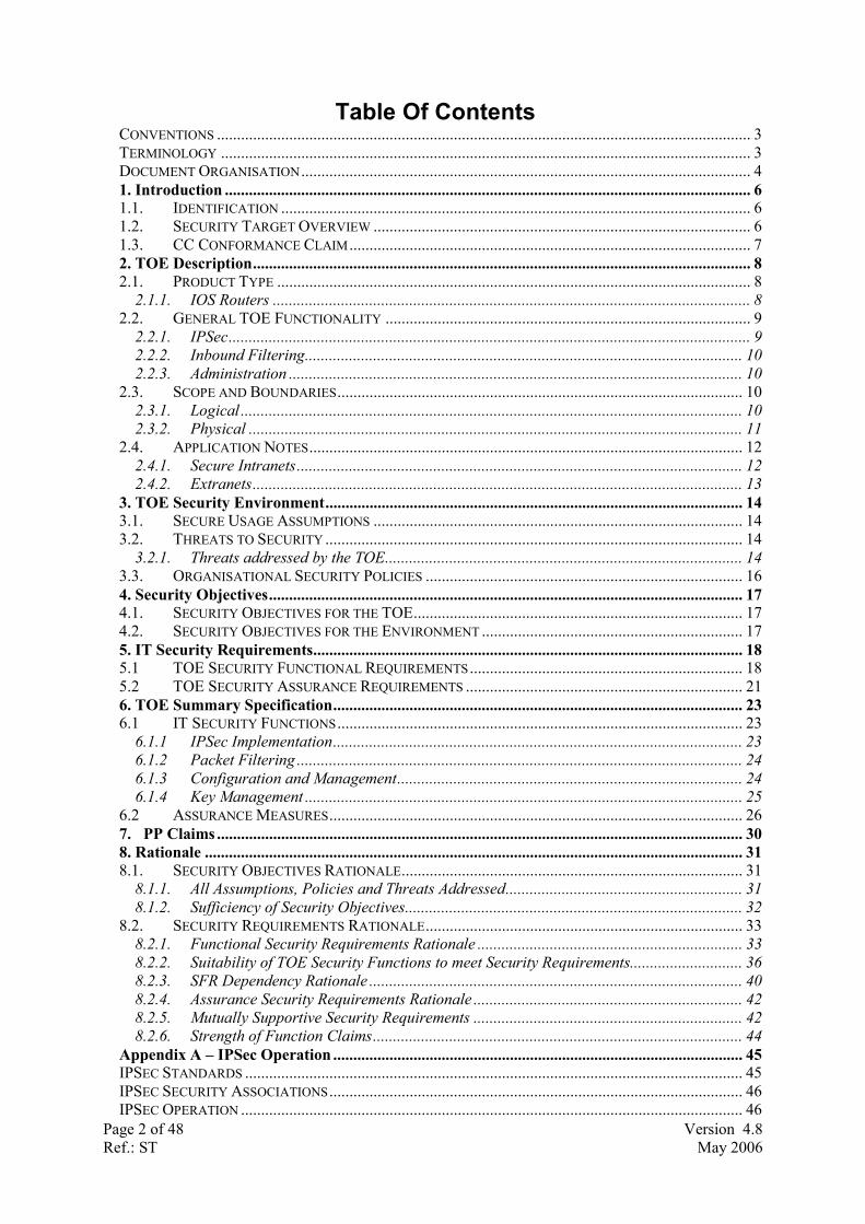
72001 7204, 7206 SA-VAM21 12.3(6a)
7300 7301 SA-VAM21 12.3(6a)
Notes:
1. The AIM-VPN/BPII, AIM-VPN/EPII, AIM-VPN/HPII and VAM2 do not support RSA public/private keys pairs for IKE authentication.
1.3. CC Conformance Claim The TOE conforms with the following parts of the CC (Version 2.1):
�� Part 2 extended; and
�� Part 3 conformant with the EAL 4 assurance measures.

Page 8 of 48 Version 4.8Ref.: ST May 2006
2. TOE Description
This section provides context for the TOE evaluation by identifying the product type and describing the evaluated configuration.
2.1. Product Type The TOE operates within routers (which are internetworking devices) running the Cisco Internetwork Operating System (IOS).
Routers that support the TOE have a number of common hardware characteristics. �� Central processor that supports all system operations, eg. Intel Pentium, PowerPC, MIPS �� Dynamic memory, used by the central processor for all system operations �� Flash memory, used to store the operating system image �� Non-volatile memory, which stores configuration parameters used to initialise the system at
system startup �� Multiple physical network interfaces (minimally two). Some models will have a fixed number
and/or type of interfaces; some models will have slots that accept additional network interfaces.
Figure 2-1 - Common hardware components of a Cisco router
The basic operation of a router is as follows:
1. At system startup the operating system is transferred from flash memory to dynamic memory using a built-in hardware bootstrap (some models execute the operating systems directly from flash memory).
2. The operating system reads the configuration parameters from non-volatile memory, builds the necessary data structures in dynamic memory and commences operation.
3. IP packets are forwarded to the router over one or more of it’s physical network interfaces, which processes them according to the system’s configuration and state information dynamically maintained by the router. This processing typically results in the IP packets being forwarded out of the router over another interface, or dropped in accordance with a configured policy.
2.1.1. IOS Routers Routers forward packets from one network segment to another based on network layer information (eg. IP address). Interconnected routers will exchange information to determine the optimal path along which network traffic should be forwarded. The primary function of a
CPU
DRAM
NVRAM
Flash
Network Interfaces
Fixed Modular
Page 9 of 48 Version 4.8Ref.: ST May 2006
router is to provide connectivity between networks of end systems. Routers can also filter packets to permit or deny packet flows.
All Cisco routers use common operating system software called the Internetwork Operating Systems (IOS). For a Cisco router to be compliant with the TOE, it must be equipped with a version of the IOS software that includes the IPSec function and configured in accordance with the TOE. The TOE-compliant software versions are identified in Section 1.2.
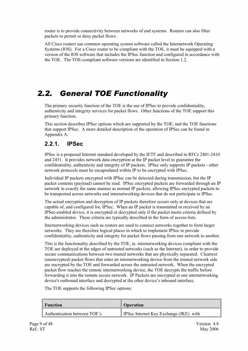
2.2. General TOE Functionality The primary security function of the TOE is the use of IPSec to provide confidentiality, authenticity and integrity services for packet flows. Other functions of the TOE support this primary function.
This section describes IPSec options which are supported by the TOE, and the TOE functions that support IPSec. A more detailed description of the operation of IPSec can be found in Appendix A.
2.2.1. IPSec IPSec is a proposed Internet standard developed by the IETF and described in RFCs 2401-2410 and 2451. It provides network data encryption at the IP packet level to guarantee the confidentiality, authenticity and integrity of IP packets. IPSec only supports IP packets - other network protocols must be encapsulated within IP to be encrypted with IPSec.
Individual IP packets encrypted with IPSec can be detected during transmission, but the IP packet contents (payload) cannot be read. IPSec encrypted packets are forwarded through an IP network in exactly the same manner as normal IP packets, allowing IPSec encrypted packets to be transported across networks and internetworking devices that do not participate in IPSec.
The actual encryption and decryption of IP packets therefore occurs only at devices that are capable of, and configured for, IPSec. When an IP packet is transmitted or received by an IPSec-enabled device, it is encrypted or decrypted only if the packet meets criteria defined by the administrator. These criteria are typically described in the form of access-lists.
Internetworking devices such as routers are used to connect networks together to form larger networks. They are therefore logical places in which to implement IPSec to provide confidentiality, authenticity and integrity for packet flows passing from one network to another.
This is the functionality described by the TOE, ie. internetworking devices compliant with the TOE are deployed at the edges of untrusted networks (such as the Internet), in order to provide secure communications between two trusted networks that are physically separated. Cleartext (unencrypted) packet flows that enter an internetworking device from the trusted network side are encrypted by the TOE and forwarded across the untrusted network. When the encrypted packet flow reaches the remote internetworking device, the TOE decrypts the traffic before forwarding it into the remote secure network. IP Packets are encrypted at one internetworking device's outbound interface and decrypted at the other device’s inbound interface.
The TOE supports the following IPSec options:
Function Operation
Authentication between TOE’s IPSec Internet Key Exchange (IKE) with

Page 10 of 48 Version 4.8Ref.: ST May 2006
�� Pre-Shared Keys,
�� RSA1 Public/Private Keys, or
�� Digital Certificates
Confidentiality of Packet Flows IPSec Encapsulating Security Payload (ESP) with
�� DES, or
�� Triple DES
Using IPSec Tunnel or Transport Mode
Integrity and Authenticity of Packet Flows
IPSec Encapsulating Security Payload (ESP) with
�� HMAC Keyed Hash Algorithm, using
�� SHA-1, or
�� MD-5
Using IPSec Tunnel or Transport Mode
Notes:
1. The AIM-VPN/BPII, AIM-VPN/EPII, AIM-VPN/HPII and VAM2 do not support RSA public/private keys pairs for IKE authentication.
2.2.2. Inbound Filtering To enable a router configured with IPSec to be “self defending” the TOE includes the inbound filtering functions of the router operating system. This allows (for example) IP packets that are not IPSec to be ignored by the router, which is particularly important as the TOE will typically operate in a router connected to an untrusted network.
2.2.3. Administration Because the IPSec function is imbedded within the router operating system software, configuration, management and operation of IPSec must be undertaken through the normal administrative interfaces provided by the router (console, telnet, SNMP, syslog, etc). The TOE therefore includes these functions. To ensure that only authorised administrator can gain secure access to these interfaces, the security target specifies that remote management be conducted from a management station connected to a trusted network behind a TOE-enabled router with IPSec connections to the remote routers (see section 2.4). Furthermore, SNMP is only supported in read-only mode to exclude the possibility that the TOE operation could be modified via SNMP.
2.3. Scope and Boundaries
2.3.1. Logical The TOE is a software function, with optional hardware acceleration, within Cisco routers. Routers are dedicated hardware devices with purpose written software that perform many networking functions. The TOE only addresses: �� The IPSec function (which provides confidentiality, authenticity and integrity for selected
packet flows transmitted and received by the router), and �� Functions relevant to the secure configuration and operation of the IPSec function.

Page 11 of 48 Version 4.8Ref.: ST May 2006
This is shown in the diagram below (note that the IPSec hardware provides no additional functions other than increasing performance of the IPSec function).
Figure 2-12 - IPSec within the TOE
Figure 2-13 illustrates the fact that the TOE operates as an overlay capability to a standard internetworking device.
Internetworking Device(Router)
Internetworking Device withIPSec (TOE)
Figure 2-13 – TOE Overlay Capability
2.3.2. Physical The products within which the TOE resides are internetworking devices (routers) and hence have two or more network interfaces. When the TOE is in use, at least one of the network interfaces of the internetworking device will be attached to a trusted network, and at least one other interface will be attached to an untrusted network. The TOE configuration will determine how packet flows received on one interface will be transmitted on another. Typically, for packet flows that are to be protected by the TOE security functions, packet flows received on trusted network interfaces will be encrypted using IPSec before being transmitted out an untrusted interface.

Page 12 of 48 Version 4.8Ref.: ST May 2006
2.4. Application Notes The products defined by the TOE are used to construct secure Intranets and Extranets.
2.4.1. Secure Intranets Within an Intranet, there maybe some network segments that are not trusted because they are physically insecure or outside the control of the owners of the Intranet. Examples include wide area links provides by a carrier, microwave links, wireless links and links shared with other organisations, as shown below:
Figure 2-14 - Insecure Intranet
The Intranet may also include transmission paths that cross an insecure network not controlled by the owner of the Intranet. A common example is the interconnection of two networks trusted by the same organisation over the Internet.
In both these cases, the Intranet owner may wish to provide confidentiality, authenticity and integrity for packet flows transmitted over the untrusted portions of the Intranet. The TOE provides this as a functional extension to existing internetworking devices thereby creating a secure Intranet, as shown below:
Internetworking Device
Trusted LogicalNetwork Path
Untrusted PhysicalNetwork Link
Trusted Network
Untrusted Network
Management System

Page 13 of 48 Version 4.8Ref.: ST May 2006
Figure 2-15 - Secure Intranet
Note that the TOE allows the remote internetworking devices to be securely managed and operated by locating the management system on a trusted network and using the confidentiality, authenticity and integrity security services of the TOE to protect packet flows from the management system to the TOE, in addition to protecting packet flows between trusted networks (as shown above).
2.4.2. Extranets The TOE enables two or more Intranets, interconnected by an untrusted network such as the public Internet, to exchange packet flows in a manner that guarantees the confidentiality, authenticity and integrity of each packet flow. This is shown below:
Figure 2-16 - Secure Extranet
Internetworking Device
Trusted LogicalNetwork Path
Untrusted PhysicalNetwork Link
Trusted Network
Untrusted Network
Management System
Internetworking Device
Trusted LogicalNetwork Path
Untrusted PhysicalNetwork Link
Trusted Network
Untrusted Network
Management System

Page 14 of 48 Version 4.8Ref.: ST May 2006
3. TOE Security Environment
In order to clarify the nature of the security problem that the TOE is intended to solve, this section describes the following: �� Any assumptions about the security aspects of the environment and/or of the manner for which the
TOE is intended. �� Any known or assumed threats to the assets against which specific protection within the TOE or
its environment is required. �� Any organisational security policy statements or rules with which the TOE must comply.
3.1. Secure Usage Assumptions The following assumptions are made in relation to the operation of the TOE:
Name Description
A.NoEvil As the security functions of the TOE can be compromised by an authorised administrator, administrators are assumed to be non-hostile and trusted to perform their duties correctly.
A.PhySec As the security functions of the TOE can be compromised by an attacker with physical access to the internetworking device containing the TOE, it is assumed that the internetworking device containing the TOE is located in a physically secure environment.
A.Training As the security functions of the TOE can be compromised due to errors or omissions in the administration of the security features of the TOE, it is assumed that administrators of the TOE have been trained to enable them to securely configure the TOE.
A.Trusted-CA As the security functions of the TOE when configured to use digital certificates can be comprised if the Certificate Authority (CA) that issued the certificates is not operated in a trusted manner, it is assumed that if the TOE is configured to use digital certificates, the issuing CA is trusted or evaluated to at least the same level as the TOE.
A.SecureTimeSource Clock sources external to the scope of the TOE should be placed in a secure location, and configured accurately so as to provide a trusted clock source for the TOE's internal clock. This includes hardware clocks within the TOE casing or Network Time Protocol (NTP) servers located on a trusted network.
Table 3-1 - Secure Usage Assumptions
3.2. Threats to Security The Threat agents against the TOE are attackers with expertise, resources, and motivation that combines to be a low attack potential.
3.2.1. Threats addressed by the TOE The TOE addresses the following threats: Name Description
T.Attack An attacker (whether an insider or outsider) may gain access to the TOE and

Page 15 of 48 Version 4.8Ref.: ST May 2006
compromise its security functions by altering its configuration. T.Untrusted-Path An attacker may attempt to disclose, modify or insert data within packet
flows transmitted/received by the TOE over an untrusted network. If such an attack was successful, then the confidentiality, integrity and authenticity of packet flows transmitted/received over an untrusted path would be compromised.
Table 3-2 - Threats Addressed by the TOE

Page 16 of 48 Version 4.8Ref.: ST May 2006
3.3. Organisational Security Policies The table following describes the organisational security policies relevant to the operation of the TOE.
Name Description P.Connectivity The organisational security policy will
a) Specify whether networks connected to the TOE are trusted or untrusted,b) Define which packet flows are to be protected by the TOE, and c) Associate each protected packet flow with a peer TOE that will
decrypt/encrypt the flow. Table 3-4 - Organisational Security Policies
The organisational security policy, P.Connectivity, is required because it determines how packet flows between trusted networks can be transmitted over an untrusted network. Each instance of the TOE implements a portion of P.Connectivity, which must be matched to, and consistent with, other instances of the TOE for the TOE security functions to be effective.
Figure 3-1 – Organisational Security Policy
For example, in figure 3-1, an instance of the TOE, D1, has three trusted networks attached to it (N1, N2, N3). It implements the following policy for three trusted network to network packet flows (red) and three secure management packet flows (green) that cross the untrusted network (U1):
Source Destination Peer TOE N1 N6 D4 N1 N5 D3 N3 N4 D2 N2 D2 D2 N2 D3 D3 N2 D4 D4
Note that in this example, flows are identified solely by the source and destination addresses of IP packets within the flow. As the TOE D1 transmits a packet flow into the untrusted network it encrypts only that traffic which matches the encryption policy, using an encryption key that has been negotiated with the matching peer. Each peer TOE of D1 must have a matching policy implemented to successfully encrypt/decrypt any flow in accordance with P.Connectivity.
Internetworking Device with TOE
Trusted LogicalNetwork Paths
Untrusted PhysicalNetwork Link
Trusted Network
Untrusted Network
Management System
N6
N1
N2 N3
N4
N5
D1
D2
D3
D4
U1

Page 17 of 48 Version 4.8Ref.: ST May 2006
4. Security Objectives
The security objectives are a high-level statement of the intended response to the security problem. These objectives indicate how the security problem, as characterised in the "Security Environment" section of the ST (Section 3), is to be addressed.
Table 4-1 describes security objectives for the TOE, while Table 4-2 describes objectives for the environment.
4.1. Security Objectives for the TOE Name Description
O.Authenticity The TOE must provide the means for ensuring that a packet flow has been received from a trusted source.
O.Confidentiality The TOE must protect the confidentiality of packet flows transmitted to/from the TOE over an untrusted network.
O.Integrity The TOE must ensure that any attempt to corrupt or modify a packet flow transmitted to/from the TOE is detected.
O.Key-Confidentiality
The TOE must provide the means of protecting the confidentiality of cryptographic keys when they are used to encrypt/decrypt packet flows between instances of the TOE and when kept in short and long-term storage.
O.NoReplay The TOE must provide a means to detect that a packet flow transmitted to the TOE has not been copied by an eavesdropper and retransmitted to the TOE.
O.Secure-Operation The TOE must prevent unauthorised changes to its configuration.
Table 4-1 - Security Objectives for the TOE
4.2. Security Objectives for the Environment Name Description
OE.Policy Those responsible for the administration of the TOE must provide a policy that specifies
a) Whether networks connected to the TOE are trusted or untrusted, b) The packet flows that are to be protected by the TOE, and c) The peer TOE that will encrypt/decrypt each packet flow.
OE.Secure-Management
Those responsible for the operation of the TOE must ensure that the TOE environment is physically secure, and management and configuration of the security functions of the TOE are: a) initiated from a management station connected to a trusted network and protected using the security functions of the TOE, b) undertaken by trusted staff trained in the secure operation of the TOE, c) implemented in conjunction with an evaluated or trusted Certificate Authority (CA), if digital certificates are used for TOE authentication, and d) configured to interface only to trusted clock sources.
Table 4-2 - Security Objectives for the Environment

Page 18 of 48 Version 4.8Ref.: ST May 2006
5. IT Security Requirements
5.1 TOE Security Functional Requirements The TOE functional security requirements are drawn from [CC] Part 2 with the exception of FAU_AUD.1, which is a bespoke security functional component, based on the [CC] Part 2 component FAU_GEN.1.
It was found to be necessary to include FAU_AUD.1 instead of FAU_GEN.1 as the requirements imposed by FAU_GEN.1 are not appropriate for the TOE. The TOE does not record the startup and shutdown of audit functions as the TOE has no facility to shutdown the audit functionality. Additionally, the TOE is designed to remain operational at all times, making the requirement for audit of startup and shutdown redundant.
Selections are enclosed in [square brackets], assignments are enclosed in [square brackets and underlined], refinements are in bold and/or strikethrough.
5.1.1 - Audit data generation (FAU_AUD.1) The TSF shall be able to generate an audit record of the following auditable events: a) All auditable events for the [not specified] level of audit; and
b) [ Errors during IKE processing, Errors during IPSEC processing, When a packet matches a filtering rule, and Errors during digital certificate processing ]
The TSF shall record within each audit record at least the following information:
a) Date and time of the event, type of event, subject identity, and the outcome (success or failure) of the event; and
b) For each audit event type, based on the auditable event definitions of the functional components included in the PP/ST, [no other audit relevant information] FAU_AUD.1.2
5.1.2 - Audit Review (FAU_SAR.1) The TSF shall provide [authorised users] with the capability to read [all audit information] from the audit records.FAU_SAR1.1 The TSF shall provide the audit records in a manner suitable for the user to interpret the information.FAU_SAR.1.2
5.1.3 - Enforced proof of origin (FCO_NRO.2) The TSF shall enforce the generation of evidence of origin for transmitted [IP packets protected by the information flow control policy] at all times.FCO_NRO.2.1 The TSF shall be able to relate the [IPSec SA peer] of the originator of the information, and the [digital signature] of the information to which the evidence applies.FCO_NRO.2.2 The TSF shall provide a capability to verify the evidence of origin of information to [the receiving TOE] given [the successful establishment of an IPSec SA with the transmitting TOE].FCO_NRO.2.3 5.1.4 - Cryptographic key generation (FCS_CKM.1) (1) RSA The TSF shall generate cryptographic keys in accordance with a specified cryptographic key generation algorithm [RSA] and specified cryptographic key sizes [512, 1024 bits] that meet the following: [PKCS #1].FCS_CKM.1.1

Page 19 of 48 Version 4.8Ref.: ST May 2006
5.1.5 - Cryptographic key generation (FCS_CKM.1) (2) Diffie-Hellman The TSF shall generate cryptographic keys in accordance with a specified cryptographic key generation algorithm [Diffie-Hellman key agreement] and specified cryptographic key sizes [56 bit, 168 bit] that meet the following: [PKCS #3].FCS_CKM.1.1 5.1.6 - Cryptographic key destruction (FCS_CKM.4) The TSF shall destroy cryptographic keys in accordance with a specified cryptographic key destruction method [overwrite] that meets the following: [no standard].FCS_CKM.4.1 5.1.7 - Cryptographic operation (FCS_COP.1(1)) – Encryption
The TSF shall perform [bulk encryption and decryption] in accordance with a specified cryptographic algorithms [DES, 3DES] and cryptographic key sizes [56 bit, 168 bit] that meet the following: [FIPS 46-3, FIPS 46-3].FCS_COP.1.1
5.1.8 - Cryptographic operation (FCS_COP.1(2)) – Signing The TSF shall perform [digital signing and signature verification] in accordance with a specified cryptographic algorithm [SHA-1, MD5] and cryptographic key sizes [160 bit, 128 bit] that meet the following: [RFC 2404, RFC 2403].FCS_COP.1.1 5.1.9 - Subset information flow control (FDP_IFC.1)
The TSF shall enforce the [information flow control SFP] on [
Subject: instances of the TOE
Information: packet flows
Operations: IP packet forwarding, secure remote management].FDP_IFC.1.1 5.1.10 - Simple security attributes (FDP_IFF.1) The TSF shall enforce the [information flow control SFP] based on the following types of subject and information security attributes: [ Subject (TOE instance) Security Attributes
�� Policy settings �� TOE identity credentials Information Security Attributes
�� Receiving/transmitting interface; �� Source/destination IP address; �� Source/destination port number; �� IPSec attributes (eg ESP header)].FDP_IFF.1.1
The TSF shall permit an information flow between a controlled subjects and of controlled information via a controlled operation if the following rules hold: [if one TOE instance (subject) can authenticate another TOE instance (subject) through the establishment of an IPSec Security Association using the configured policy and identity credentials of the TOE instances]. FDP_IFF.1.2 The TSF shall enforce [no additional information flow control SFP rules].FDP_IFF.1.3 The TSF shall provide the following [inbound packet filtering] additional capabilities.FDP_IFF.1.4 The TSF shall explicitly authorise an information flow based on the following rules: [none].FDP_IFF.1.5 The TSF shall explicitly deny an information flow based on the following rules:[the administrator-configured explicit “deny” rules based on the above Information Security Attributes].FDP_IFF.1.6 5.1.11 - Basic data exchange confidentiality (FDP_UCT.1)

Page 20 of 48 Version 4.8Ref.: ST May 2006
The TSF shall enforce the [information flow control SFP] to be able to [transmit and receive] objects in a manner protected from unauthorised disclosure.FDP_UCT.1.1 5.1.12 - Data exchange integrity (FDP_UIT.1) The TSF shall enforce the [information flow control SFP] to be able to [transmit and receive] user data packet flows in a manner protected from [modification, insertion and replay] errors.FDP_UIT.1.1 The TSF shall be able to determine on receipt of user data a packet flow, whether [modification, insertion and replay] has occurred. FDP_UIT.1.2 5.1.13 - User authentication before any action (FIA_UAU.2) The TSF shall require each user to be successfully authenticated before allowing any other TSF-mediated actions on behalf of that user.FIA_UAU.2.1 5.1.14 - Multiple authentication mechanisms (FIA_UAU.5)
The TSF shall provide [password only mechanism; or the combination of username with matching password] to support user authentication.FIA_UAU.5.1 The TSF shall authenticate any user's claimed identity according to the [mechanism as defined in the TOE configuration by the privileged administrator]. FIA_UAU.5.2
5.1.15 - User identification before any action (FIA_UID.2) The TSF shall require each user to identify itself before allowing any other TSF-mediated actions on behalf of that user. FIA_UID.2.1 5.1.16 - Management of security functions behaviour (FMT_MOF.1) The TSF shall restrict the ability to [determine the behaviour of, disable, enable, and modify the behaviour of] the functions [that implement the information flow control SFP] to [privileged administrators]. FMT_MOF.1.1 5.1.17 - Management of security attributes (FMT_MSA.1) The TSF shall enforce the [information flow control SFP] to restrict the ability to [query, modify and delete] the security attributes [TSF configuration] to [privileged administrator.]FMT_MSA.1.1 5.1.18 - Secure security attributes (FMT_MSA.2) The TSF shall ensure that only secure values are accepted for security attributes.FMT_MSA.2.1 5.1.19 - Static attribute initialisation (FMT_MSA.3) The TSF shall enforce the [information flow control SFP] to provide [restrictive] default values for security attributes that are used to enforce the SFP.FMT_MSA.3.1 The TSF shall allow the [privileged administrator] to specify alternative initial values to override the default values when an object or information is created. FMT_MSA.3.2 5.1.20 - Management of TSF data (FMT_MTD.1) The TSF shall restrict the ability to [query, modify, delete and clear] the [TSF configuration] to [privileged administrator].FMT_MTD.1.1 5.1.21 - Specification of Management Functions (FMT_SMF.1) The TSF shall be capable of performing the following security management functions: [
a) determine the behaviour of, the configuration of functions that implement information flow control SFP;
b) configure the cryptographic TSFs;
c) configure audit management;
d) view all audit information in a manner suitable for interpretation;
Page 21 of 48 Version 4.8Ref.: ST May 2006
e) query, modify and delete the information flow control SFP and its security attributes;
f) create, delete and modify usernames for use with administration of the TOE; and
g) configure system time attributes. ]. FMT_SMF.1.1 5.1.22 - Restrictions on security roles (FMT_SMR.2) The TSF shall maintain the roles: [administrator and privileged administrator]. FMT_SMR.2.1 The TSF shall be able to associate users with roles.FMT_SMR.2.2 The TSF shall ensure that the conditions [that a user has to be authenticated as an administrator before they can be allowed to authenticate as a privileged administrator] are satisfied.FMT_SMR.2.3 5.1.23 - Assuming roles (FMT_SMR.3) The TSF shall require an explicit request to assume the following roles: [privileged administrator]. FMT_SMR.3.1 5.1.24 - Reliable time stamps (FPT_STM.1) The TSF shall be able to provide reliable time stamps for its own use. FPT_STM.1.1 5.1.25 - Abstract machine testing (FPT_AMT.1) The TSF shall run a suite of tests [during initial start-up] to demonstrate the correct operation of the security assumptions provide by the abstract machines that underlies the TSF.FPT_AMT.1 5.1.26 - TSF testing (FPT_TST.1) The TSF shall run a suite of self tests [during initial start-up] to demonstrate the correct operation of the TSF.FPT_TST.1.1 The TSF shall provide authorised users with the capability to verify the integrity of TSF data. FPT_TST.1.2 The TSF shall provide authorised users with the capability to verify the integrity of stored TSF executable code.FPT_TST.1.3 5.1.27 - TOE session establishment (FTA_TSE.1) The TSF shall be able to deny session establishment based on [access control list specifying a combination of source/destination IP address and source/destination TCP/UDP port number].FTA_TSE.1.1 5.1.28 - Inter-TSF trusted channel (FTP_ITC.1) The TSF shall provide a communication channel between itself and a remote trusted IT product that is logically distinct from other communication channels and provides assured identification of its end points and protection of the channel data from modification or disclosure.FTP_ITC.1.1 The TSF shall permit [the TSF] to initiate communication via the trusted channel.FTP_ITC.1.2 The TSF shall initiate communication via the trusted channel for [the secure transmission of packet flows between trusted networks, and secure administration and operation of the TOE].FTP_ITC.1.3
5.2 TOE Security Assurance Requirements The TOE meets all the Assurance Requirements prescribed by EAL4 in Part 3 of the CC. They are summarised by Assurance Class in Table 5-1.
Assurance Class Assurance Components ACM ACM_AUT.1 ACM_CAP.4 ACM_SCP.2 ADO ADO_DEL.2 ADO_IGS.1

Page 22 of 48 Version 4.8Ref.: ST May 2006
ADV ADV_FSP.2 ADV_HLD.2 ADV_IMP.1 ADV_LLD.1 ADV_RCR.1 ADV_SPM.1 AGD AGD_ADM.1 AGD_USR.1 ALC ALC_DVS.1 ALC_LCD.1 ALC_TAT.1 ATE ATE_COV.2 ATE_DPT.1 ATE_FUN.1 ATE_IND.2 AVA AVA_MSU.2 AVA_SOF.1 AVA_VLA.2
Table 5-1 - Assurance Requirements: EAL4

Page 23 of 48 Version 4.8Ref.: ST May 2006
6. TOE Summary Specification This section presents the Security Functions implemented by the TOE and the Assurance Measures applied to ensure their correct implementation.
6.1 IT Security Functions This section presents the security functions performed by the TOE and provides a mapping between the identified security functions and the Security Functional Requirements that it must satisfy.
6.1.1 IPSec Implementation The TOE implements the IETF IPSec protocols (RFCs 2401-2410) to provide confidentiality, authenticity and integrity for packet flows transmitted from and received by the TOE. The TOE IPSec implementation contains a number of functional components that meet the IPSec TSF.
IPSEC.1 - IPSec Internet Key Exchange (IKE)
IKE authenticates IPSec peers (remote TOEs) using pre-shared keys, RSA keys1 or digital certificates. It also handles the agreement of secure session keys using the Diffie-Hellman algorithm and negotiates the parameters used during IPSec ESP (IPSEC.2)
IKE maintains a trusted channel, referred to as a Security Association (SA), between IPSec peers that is also used to manage IPSec connections, including:
�� The negotiation of mutually acceptable IPSec options between peers, �� The establishment of additional Security Associations to protect packets
flows using ESP (as per IPSEC.2), and �� The agreement of secure bulk data encryption (DES (56-bit) /3DES (168-
bit)) keys for use with ESP (IPSEC.2).
1 The AIM-VPN/BPII, AIM-VPN/EPII, AIM-VPN/HPII and VAM2 do not support RSA public/private keys pairs for IKE authentication.

Page 24 of 48 Version 4.8Ref.: ST May 2006
IPSEC.2 - IPSec Encapsulating Security Payload (ESP)
The TOE uses ESP to protect packet flows between IPSec peers (instances of the TOE) across intervening untrusted networks in accordance with a TOE security policy (TSP). ESP is a method of encapsulating IP Packets and provides confidentiality using the DES and 3DES ciphers, integrity and authenticity using the MD5 and SHA-1 algorithms, and a mechanism to detect the capture and retransmission of packets (replay attacks). The parameters used by ESP, including session encryption keys, are negotiated via IPSec security associations (SAs) established via IKE (IPSEC.1) in accordance with the TSP. Note that security associations are unidirectional so that between IPSec peers protecting a packet flow (labelled A and B for example) there are at least two SA’s - one from A to B and one from B to A. Each SA, and associated session encryption key, has a lifetime, which upon expiry results in a new SA and session encryption key being established by the SA peers. The packet flows between two remote IPSec peers that are to be protected by the TOE are defined by way of cryptographic maps (IPSEC.3).
IPSEC.3 - Cryptographic Maps
Cryptographic Maps are used by the TOE to specify: a) the packet flow (ie. IP packets) that are to be protected by encryption, identified by an access-control list that can include IP protocol, source/destination IP address and source/destination UDP/TCP port number; b) the IPSec options and parameters to be used when performing encryption; c) how to identify the peer TOE that will decrypt the packet flow;
d) the interface(s) of the TOE-enabled router that are enabled for IPSec using the parameters specified above.
6.1.2 Packet Filtering The TOE prevents attempts to establish management control connections to the TOE itself by rejecting packet flows (ie. IP packets) that are not consistent with the information flow SFP.
PACKETFILTER.1 - Packet Filtering The TOE performs input packet filtering by applying an access-control list to specific interfaces of the TOE-enabled router. The access-control list can include IP protocol, source/destination IP address and source/destination UDP/TCP port number. Packets not matching the access-list are logged and discarded by the router.
6.1.3 Configuration and Management The TOE includes functions that allow the configuration and operation of the security functions of the TOE to be controlled and monitored. The TOE also supports the ability to maintain real time.

Page 25 of 48 Version 4.8Ref.: ST May 2006
CONFIG.1 - System Messages The TOE generates system diagnostic messages that identify specific TOE operations – errors during IKE negotiation, errors during IPSec processing, whenever a packet matches a filtering rule, and any errors encountered during digital certificate processing. For each event, the TSF shall record the date and time of each event, the type of event, the affected subject identity and the outcome of the event (FAU_AUD.1). Logged messages for these events can be directed to a combination of an interactive management session, a buffer within the TOE or to an external system outside of the TOE using the SYSLOG protocol. Using the “show logging” command, the authorised user can review the audit messages stored in the buffer on the TOE and act upon them as required (FAU_SAR.1).
CONFIG.2 - Management Interfaces The TOE can be configured, managed and operated either via direct local connection to a physical console port, or remotely via an in-band network connection. All management connections must be explicitly enabled to be used, these include:
�� Interactive command line interface (CLI) via console or telnet; �� TFTP download of configurations and operating system software; �� Simple Network Management Protocol (SNMP) in read-only mode for monitoring Interactive CLI connections (console or telnet) require user authentication. The TOE shall be configured to require an access password, which provides unprivileged access and an enable password which provides privileged management access. After successful authentication via the CLI interface, an authorised user can upload or download configuration files to/from a TFTP server. The privileged administrator has control over all TOE functions, attributes, and data, either by executing commands, viewing status and configuration, or editing the TOE configuration settings. The default configuration will be secure so that packet flows will not occur. The privileged administrator has the right to change from the default to allow packet flows. The TOE will conduct self-tests upon startup to verify that it is operating correctly.
CONFIG.3 - Management of Time The TOE maintains real time using a reliable software clock that interfaces to an internal hardware clock, or the Network Time Protocol (NTP).
6.1.4 Key Management To support the authentication of one TOE to another TOE, the TOE supports the use of public key cryptography.

Page 26 of 48 Version 4.8Ref.: ST May 2006
KEYMGT.1 - Key Management The TOE generates secure RSA public/private keys (512 and 1024 bit key lengths) for use with a Public Key Infrastructure (PKI). The TOE interacts with a certificate authority using the Simple Certificate Enrollment Protocol (SCEP) to download a certificate authority's digital certificate and to request and download a digital certificate for the TOE itself. The TOE can destroy keys it creates by overwriting them.
TSS Reference IT Security Function Functional Component Functional Requirement
IPSEC.1 IPSec Internet Key Exchange (IKE)
FCS_CKM.1(2) FTP_ITC.1 FMT_MSA.2
Cryptographic key generation (Diffie Hellman) Inter-TSF trusted channel Secure security attributes
IPSEC.2 IPSec Encapsulating Security Payload (ESP)
FCO_NRO.2 FCS_COP.1 (1) FCS_COP.1 (2) FDP_UCT.1 FDP_UIT.1 FTP_ITC.1
Enforced proof of origin Cryptographic operation (Encryption) Cryptographic operation (Signing) Basic data exchange confidentiality Data exchange integrity Inter-TSF trusted channel
IPSEC.3 Cryptographic Maps FDP_IFC.1 FDP_IFF.1 FTP_ITC.1
Subset information flow control Simple security attributes Inter-TSF trusted channel
PACKETFILTER.1 Packet Filtering FTA_TSE.1 FDP_IFF.1 FDP_IFC.1
TOE session establishment Simple security attributes Subset information flow control
CONFIG.1 System Messages FAU_AUD.12 FAU_SAR.1 FMT_SMF.1
Audit data generation Audit Review Specification of Management Functions
CONFIG.2 Management Interfaces FIA_UAU.2 FIA_UAU.5 FIA_UID.2 FMT_SMR.2 FMT_SMR.3 FMT_MOF.1 FMT_MSA.1 FMT_MSA.3 FMT_MTD.1 FPT_AMT.1 FPT_TST.1 FMT_SMF.1
User authentication before any action Multiple authentication mechanisms User identification before any action Restrictions on security roles Assuming roles Management of security functions behaviour Management of security attributes Static attribute initialisation Management of TSF data Abstract machine testing TSF testing Specification of Management Functions
CONFIG.3 Management of Time FPT_STM.1 FMT_SMF.1
Reliable time stamp Specification of Management Functions s
KEYMGT.1 Key Management FCS_CKM.1 (1) FCS_CKM.4 FMT_MSA.2
Cryptographic key generation Cryptographic key destruction Secure security attributes
Table 6-1 - Mapping Summary Specifications to Functional Requirements
6.2 Assurance Measures The purpose of this section is to show that the identified assurance measures are appropriate to meet the assurance requirements by mapping the identified assurance measures onto the assurance requirements. The Assurance Measures that demonstrate the correct implementation of the Security Functions of the TOE are as follows:
2 FAU_AUD.1 is a bespoke component based on the [CC] Part 2 component FAU_GEN.1.

Page 27 of 48 Version 4.8Ref.: ST May 2006
�� User Guidance (UG) Documentation �� Functional Specification (FSP) Document �� Security Policy Model (SPM) Document �� High Level Design (HLD) Document �� Low Level Design (LLD) Documentation �� Configuration Management Plan (CMP) Document �� Analysis of Testing (ATE) Document �� Security Functional Analysis (SFA) Document �� Vulnerability Assessment (VA) Document
Table 6-2 below demonstrates that the identified assurance measures completely meet the assurance requirements by showing that all requirements are mapped to an assurance measure.
CC Assurance Component Assurance Measure
ACM_AUT.1 Partial CM automation Configuration Management Plan ACM_CAP.4 Generation support and
acceptance procedures Configuration Management Plan
ACM_SCP.2 Problem tracking CM coverage
Configuration Management Plan
ADO_DEL.2 Detection of modification Configuration Management Plan ADO_IGS.1 Installation, generation, and
start-up procedures User Guidance
ADV_FSP.2 Fully defined external interfaces
Functional Specification User Guidance
ADV_HLD.2 Security enforcing high-level design
High Level Design
ADV_IMP.1 Subset of the implementation of the TSF
Low Level Design
ADV_LLD.1 Descriptive low-level design
Low Level Design
ADV_RCR.1 Informal correspondence demonstration
Functional Specification High Level Design Low Level Design
ADV_SPM.1 Informal TOE security policy model
Security Policy Model
AGD_ADM.1 Administrator guidance User Guidance AGD_USR.1 User guidance User Guidance ALC_DVS.1 Identification of security
measures Configuration Management Plan
ALC_LCD.1 Developer defined life-cycle model
Configuration Management Plan
ALC_TAT.1 Well-defined development tools
Configuration Management Plan
ATE_COV.2 Analysis of coverage Analysis of Testing ATE_DPT.1 Testing: high-level design Analysis of Testing ATE_FUN.1 Functional testing Analysis of Testing ATE_IND.2 Independent testing -
sample Analysis of Testing, TOE

Page 28 of 48 Version 4.8Ref.: ST May 2006
AVA_MSU.2 Validation of analysis Security Functional Analysis AVA_SOF.1 Strength of TOE security
function evaluation Security Functional Analysis
AVA_VLA.2 Independent vulnerability analysis
Vulnerability Assessment
Table 6-2 – Mapping of Assurance Measures to Assurance Requirements
The assurance measures documents have been specifically written to address the assurance requirements and are structured as follows:
User Guidance (UG) �� Provides TOE users and administrators with procedural information on installation,
configuration and management of the TOE (AGD_USR.1) (AGD_ADM.1) �� Describes procedures for the installation, generation, and start-up of the TOE
(ADO_IGS.1) �� Detailed syntax information on the external interfaces used for such interaction with the
TOE (ADV_FSP.2)
Functional Specification (FSP) �� Describes the security functionality of the TOE (ADV_FSP.2) �� Defines the external interfaces to the TOE (ADV_FSP.2) �� Demonstrates correspondence with the ST (ADV_RCR.1)
Security Policy Model (SPM) �� Describes the security policy implemented by the TOE (ADV_SPM.1)
High Level Design (HLD) �� Describes the relationship between TOE sub-systems, their interfaces and the sequence of
events in response to stimulus at those interfaces. (ADV_HLD.2) �� Demonstrates correspondence with the FSP (ADV_RCR.1)
Low Level Design (LLD) �� Describes the TOE sub-systems, their interfaces and the sequence of events in response to
stimulus at those interfaces (ADV_LLD.1) �� A source code representation of the TOE. (ADV_IMP.1) �� Demonstrates correspondence with the HLD (ADV_RCR.1)
Configuration Management Plan (CMP) �� Describes the development life-cycle model (ALC_LCD.1) �� Describes the security measures for the development site (ALC_DVS.1) �� Describes the development tools (ALC_TAT.1) �� Describes the CM model (ACM_AUT.1) and how problem tracking is undertaken
(ACM_SCP.2) �� Describes the delivery procedures and how they provide for the detection of modification
(ADO_DEL.2) �� Description of TOE generation and acceptance procedures (ACM_CAP.4)
Analysis of Testing (ATE) �� Describes the testing undertaken of the TOE and the implementation of the functionality
specified in the ST and the design documentation (ATE_DPT.1) �� Describes coverage of the testing (ATE_COV.2) �� Describes the testing of security functionality (ATE_FUN.1) �� The TOE will be provided to the evaluators (ATE_IND.2)

Page 29 of 48 Version 4.8Ref.: ST May 2006
Security Functional Analysis (SFA) �� Describes vulnerability analysis undertaken (AVA_MSU.2) �� Strength of TOE security function evaluation (AVA_SOF.1)
Vulnerability Assessment (VA) �� Identifies potential vulnerabilities in the TOE and provides a rationale as to why they are
not exploitable in the intended environment for the TOE (AVA_VLA.2).

Page 30 of 48 Version 4.8Ref.: ST May 2006
7. PP Claims This Security Target was not written to conform to any Protection Profile.

Page 31 of 48 Version 4.8Ref.: ST May 2006
8. Rationale
8.1. Security Objectives Rationale The purpose of this rationale is to demonstrate that the identified security objectives are: �� suitable, they are sufficient to address the security needs; �� necessary, there are no redundant security objectives.
8.1.1. All Assumptions, Policies and Threats Addressed
Objective
Policy/ Threat/ Assumption
O.A
uthe
ntic
ity
O.C
onfid
entia
lity
O.In
tegr
ity
O.K
ey-
Con
fiden
tialit
y
O.N
oRep
lay
O.S
ecur
e-O
pera
tion
OE
.Pol
icy
OE
.Sec
ure.
Man
age
men
t
T.Attack � �
T.Untrusted-Path � � � � �
A.PhySec �
A.NoEvil �
A.Training �
A.Trusted-CA �
A.SecureTimeSource �
P.Connectivity � �
Table 8-1 - Cross Reference Objectives to Threats/Assumptions/Policies

Page 32 of 48 Version 4.8Ref.: ST May 2006
8.1.2. Sufficiency of Security Objectives The following arguments are provided to demonstrate the sufficiency of the Security Objectives outlined above:
Policies Objectives
P.CONNECTIVITY Rules for Data Flows
The objectives (OE.Policy, OE.Secure-Management) will provide complete coverage as: OE.Policy states that those responsible for the administration of the TOE will be provided with a policy that specifies: a) whether the networks which are connected to the TOE are trusted or untrusted, b) which packet flows are to be protected by the TOE, and c) the peer TOE to be associated with each data flow �� OE.Secure-Management states that those responsible for the operation of the TOE
will ensure that management and configuration functions of the security functions of the TOE are: a) initiated from a management station connected to a trusted network and protected using the security functions of the TOE
Table 8-2 - Sufficiency of Security Objectives (1)
Threat Objectives
T.ATTACK Unauthorised access
The objectives (O.Secure-Operation, OE.Secure-Management) will provide an effective countermeasure as: �� The TOE will be correctly configured in accordance with a security policy which
will prevent bypass of the TSF; �� The TSP can only be altered by a trusted administrator from a secure management
station. T.UNTRUSTED-PATH Secure transmission of packet flows
The objectives (O.Authenticity, O.Confidentiality, O.Integrity, O.Key-Confidentiality, O.NoReplay) will provide an effective countermeasure as: �� O.Authenticity ensures that packet flows are received/transmitted from/to known,
authenticated TOEs; �� O.Confidentiality ensures that the confidentiality of packet flows is maintained
during transmission; �� O.Integrity ensures that a packet flow cannot be modified without being detected by
the TOE; �� O.Key-Confidentiality ensures that cryptographic keys cannot be captured and used
to decrypt packet flows; �� O.NoReplay ensures that a packet flow transmitted to the TOE has not been copied
by an eavesdropper and retransmitted to the TOE.
Table 8-3 - Sufficiency of Security Objectives (2)
Assumption Objectives
A.PHYSEC TOE will be kept in a physically secure environment.
The objective (OE.Secure-Management) upholds the assumption as: �� The TOE will be maintained in a location, which is physically secure.
A.NOEVIL Administrators assumed to be non-hostile and trusted to perform their duties correctly.
The objective (OE.Secure-Management) upholds the assumption as: �� Those responsible for the operation of the TOE must ensure that management and
configuration of the security functions of the TOE are undertaken by trusted staff trained in the secure operation of the TOE.
A.TRAINING Administrators of the TOE have received training.
The objective (OE.Secure-Management) upholds the assumption as: �� Management and configuration of the security functions of the TOE are undertaken
by trusted staff trained in the secure operation of the TOE A.TRUSTED-CA Digital Certificates are issued from an evaluated/trusted Certificate Authority.
The objective (OE.Secure-Management) upholds the assumption as: �� Management and configuration of the security functions of the TOE are
implemented in conjunction with an evaluated or trusted Certificate Authority (CA), if digital certificates are used for TOE authentication.
A.SECURETIMESOURCE The objective (OE.Secure-Management) upholds the assumption as:

Page 33 of 48 Version 4.8Ref.: ST May 2006
Sources of time are secure. �� Management and configuration of the security functions of the TOE are
configured to interface only to trusted clock sources
Table 8-4 - Sufficiency of Security Objectives (3)
8.2. Security Requirements Rationale The purpose of this section is to show that the identified security requirements (Section 5) are suitable to meet the security objectives (Section 4). The following tables show that each security requirement (and SFRs in particular) is necessary, that is, each security objective is addressed by at least one security requirement, and vice versa.
8.2.1. Functional Security Requirements Rationale
Objective
Requirement
O.A
uthe
ntic
ity
O.C
onfid
entia
lity
O.In
tegr
ity
O.K
ey-
Con
fiden
tialit
y
O.N
oRep
lay
O.S
ecur
e-O
pera
tion
FAU_AUD.13 �
FAU_SAR.1 �
FCO_NRO.2 � �
FCS_CKM.1 (1) �
FCS_CKM.1 (2) �
FCS_CKM.4 �
FCS_COP.1(1) �
FCS_COP.1(2) � �
FDP_IFC.1 � � � � �
FDP_IFF.1 � � � � �
FDP_UCT.1 �
FDP_UIT.1 �
FIA_UAU.2 �
FIA_UAU.5 �
FIA_UID.2 �
3 FAU_AUD.1 is a bespoke component based on the [CC] Part 2 component FAU_GEN.1.

Page 34 of 48 Version 4.8Ref.: ST May 2006
Objective
Requirement
O.A
uthe
ntic
ity
O.C
onfid
entia
lity
O.In
tegr
ity
O.K
ey-
Con
fiden
tialit
y
O.N
oRep
lay
O.S
ecur
e-O
pera
tion
FMT_MOF.1 �
FMT_MSA.1 �
FMT_MSA.2 �
FMT_MSA.3 �
FMT_MTD.1 �
FMT_SMF.1 �
FMT_SMR.2 �
FMT_SMR.3 �
FPT_AMT.1 �
FPT_STM.1 �
FPT_TST.1 �
FTA_TSE.1 �
FTP_ITC.1 � � � � �
Table 8-5 - Functional Component to Security Objective Mapping
Objectives Requirements
O.AUTHENTICITY Ensure packet flows have been received from a trusted source
The SFRs [FCO_NRO.2, FCS_COP.1(2), FDP_IFC.1, FDP_IFF.1, FTP_ITC.1] are sufficient to satisfy the objective because: �� Packet flows received by the TOE must have been digitally signed
using the FCO_NRO.2 SFR with key material associated with an identified remote trusted IT product
�� The FCS_COP.1(2) SFR ensures that the received transmission is digitally signed and therefore its authenticity can be established cryptographically.
�� The information flow control SFP and the scope of control of the policies that form the identified information flow control portion of the TSP are identified and defined by the FDP_IFC.1 SFR
�� The FDP_IFF.1 SFR is used to identify which remote trusted IT product is authenticating which packet flow, and which packet flow is to be authenticated for transmission to a remote trusted IT product
�� The FTP_ITC.1 SFR establishes a trust relationship with a remote trusted IT product (eg. another instance of the TOE).
O.CONFIDENTIALITY The SFRs [FCS COP.1(1), FDP UCT.1, FDP IFC.1, FDP IFF.1,

Page 35 of 48 Version 4.8Ref.: ST May 2006
Objectives Requirements Protect the confidentiality of packet flows transmitted to/from the TOE over an untrusted network
FTP_ITC.1] are sufficient to satisfy the objective because: �� The FCS_COP.1(1) SFR ensures the confidentiality of transmissions
through strong encryption. �� The FDP_UCT.1 SFR provides confidentiality for packet flows
received by, or transmitted from, the TOE using key material associated with an identified remote trusted IT product
�� The information flow control SFP and the scope of control of the policies that form the identified information flow control portion of the TSP are identified and defined by the FDP_IFC.1 SFR
�� The FDP_IFF.1 SFR is used to identify which remote trusted IT product is providing confidentiality for which packet flow, and which packet flow is to be protected when transmitted to a remote trusted IT product
�� The FTP_ITC.1 SFR establishes a trust relationship with a remote trusted IT product (eg. another instance of the TOE)
O.INTEGRITY Any attempt to corrupt or modify a packet flow transmitted to/from the TOE is detected
The SFRs [FCS_COP.1(2), FDP_UIT.1, FDP_IFC.1, FDP_IFF.1, FTP_ITC.1] are sufficient to satisfy the objective because: �� The FCS_COP.1(2) SFR ensures that the received transmission is
digitally signed and therefore its integrity can be established cryptographically.
�� The FDP_UIT.1 SFR provides integrity for packet flows received by, or transmitted from, the TOE using key material associated with an identified remote trusted IT product
�� The information flow control SFP and the scope of control of the policies that form the identified information flow control portion of the TSP are identified and defined by the FDP_IFC.1 SFR
�� The FDP_IFF.1 SFR is used to identify which remote trusted IT product is providing integrity verification for which packet flow, and which packet flow is to be protected when transmitted to a remote trusted IT product
�� The FTP_ITC.1 SFR establishes a trust relationship with a remote trusted IT product (eg. another instance of the TOE)
O.KEY-CONFIDENTIALITY The TOE must provide the means of protecting the confidentiality of cryptographic keys when they are used to encrypt/decrypt packet flows between instances of the TOE and when kept in short and long-term storage.
The SFRs [FCS_CKM.1 (1), FCS_CKM.1 (2), FCS_CKM.4, FMT_MSA.2, FDP_IFC.1, FDP_IFF.1, FTP_ITC.1] are sufficient to satisfy the objective: �� The FCS_CKM.1 SFRs ensures that key generation is robust �� FCS_CKM.4 SFR ensures that keys can be safely destroyed �� The FCS_CKM.1 (2), SFR ensures that the establishment of the trust
relationship and the key agreement operations are cryptographically sound
�� Cryptographic keys generated are checked to ensure they are secure (FMT_MSA.2)
�� The information flow control SFP and the scope of control of the policies that form the identified information flow control portion of the TSP are identified and defined by the FDP_IFC.1 SFR
�� The FDP_IFF.1 SFR is used to identify which remote trusted IT product is providing integrity verification for which packet flow, and which packet flow is to be protected when transmitted to a remote trusted IT product
�� The FTP_ITC.1 SFR establishes a trust relationship with a remote trusted IT product (eg. another instance of the TOE)
O.NOREPLAY Provide a means to detect if an eavesdropper has copied a packet flow and retransmitting it to the TOE.
The SFRs [FCO_NRO.2, FDP_IFC.1, FDP_IFF.1, FTP_ITC.1] are sufficient to satisfy the objective because: �� The FTP_ITC.1 SFR establishes a trust relationship with a remote
trusted IT product (eg. another instance of the TOE) �� Packet flows received by the TOE are marked using the FCO_NRO.2
SFR with a sequence number that is uniquely associated with a remote trusted IT product
�� The information flow control SFP and the scope of control of the policies that form the identified information flow control portion of the TSP are identified and defined by the FDP_IFC.1 SFR
�� The FDP_IFF.1 SFR is used to identify which remote trusted IT product is providing integrity verification for which packet flow, and which

Page 36 of 48 Version 4.8Ref.: ST May 2006
Objectives Requirements packet flow is to be protected when transmitted to a remote trusted IT product
O.SECURE-OPERATION Prevent unauthorised changes to TOE configuration
The SFRs [FTA_TSE.1, FIA_UAU.2, FIA_UAU.5, FIA_UID.2, FAU_AUD.14, FAU_SAR.1, FMT_MOF.1, FMT_MSA.1, FMT_MSA.3, FMT_SMR.2, FMT_SMR.3, FMT_MTD.1, FPT_STM.1, FPT_AMT.1, FPT_TST.1,] are sufficient to satisfy the objective because: �� The TSF can reject unauthorised session establishments by applying
access control lists to deny session establishment, supported by FTA_TSE.1;
�� The FIA_UAU family supports the requirement for multiple user authentication mechanisms before any actions are carried out on the TSF;
�� The FIA_UID family supports the requirement to identify the user before any actions are taken on that user’s behalf;
�� The requirements for recording the occurrence of security relevant events that take place under TSF control and the identification of the level of auditing are provided by the FAU_AUD family, and the ability for authorised users to review this audit information is provided by FAU_SAR.1;
�� The requirement to restrict the ability to determine the behaviour of, disable, enable and modify the information flow control SFP is satisfied by FMT_MOF.1;
�� Authorised users’ control over the management of the security attributes is allowed by the FMT_MSA family;
�� The FMT_SMF.1 requirement specifies the required management functions of the TOE. These management functions includes all user management, packet filtering, IPSec and audit configuration.
�� Control over the assignment of the administrator role to different users is provided by the FMT_SMR family. No user will be able to assume the role of privileged administrator without explicitly requesting and being authenticated as having permission. Users will not be able to assume privileged administrator role unless they have first assumed the administrator role;
�� The requirement to restrict the ability to query, modify, delete and clear the TSF configuration to privileged administrators is provided by FMT_MTD.1;
�� The requirement for reliable time-stamps is satisfied by FPT_STM.1; �� The requirement for the self-testing of the abstract machine upon which
the security functions rely is satisfied by FPT_AMT.1.; �� The requirement for self-testing upon startup to verify the proper
operation of the TSF code is satisfied by FPT_TST.1
Table 8-6 - SFR Sufficiency
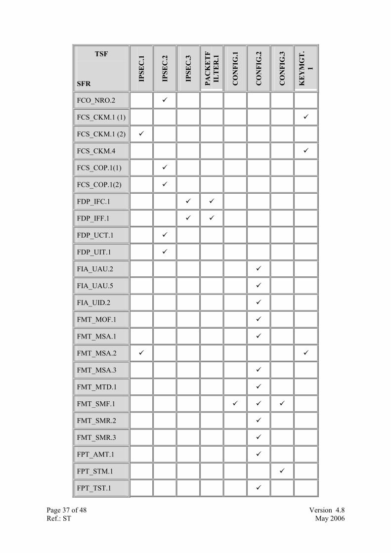
8.2.2. Suitability of TOE Security Functions to meet Security Requirements
TSF
SFR IPSE
C.1
IPSE
C.2
IPSE
C.3
PAC
KE
TF
ILT
ER
.1
CO
NFI
G.1
CO
NFI
G.2
CO
NFI
G.3
KE
YM
GT
.1
FAU_AUD.15 �
FAU_SAR.1 �
4 FAU_AUD.1 is a bespoke component based on the [CC] Part 2 component FAU_GEN.1. 5 FAU_AUD.1 is a bespoke component based on the [CC] Part 2 component FAU_GEN.1.
Page 37 of 48 Version 4.8Ref.: ST May 2006
TSF
SFR IPSE
C.1
IPSE
C.2
IPSE
C.3
PAC
KE
TF
ILT
ER
.1
CO
NFI
G.1
CO
NFI
G.2
CO
NFI
G.3
KE
YM
GT
.1
FCO_NRO.2 �
FCS_CKM.1 (1) �
FCS_CKM.1 (2) �
FCS_CKM.4 �
FCS_COP.1(1) �
FCS_COP.1(2) �
FDP_IFC.1 � �
FDP_IFF.1 � �
FDP_UCT.1 �
FDP_UIT.1 �
FIA_UAU.2 �
FIA_UAU.5 �
FIA_UID.2 �
FMT_MOF.1 �
FMT_MSA.1 �
FMT_MSA.2 � �
FMT_MSA.3 �
FMT_MTD.1 �
FMT_SMF.1 � � �
FMT_SMR.2 �
FMT_SMR.3 �
FPT_AMT.1 �
FPT_STM.1 �
FPT_TST.1 �

Page 38 of 48 Version 4.8Ref.: ST May 2006
TSF
SFR IPSE
C.1
IPSE
C.2
IPSE
C.3
PAC
KE
TF
ILT
ER
.1
CO
NFI
G.1
CO
NFI
G.2
CO
NFI
G.3
KE
YM
GT
.1
FTA_TSE.1 �
FTP_ITC.1 � � �
Table 8-7 - SFR to TSF Cross-Reference
FIA_AUD.1
The TSF CONFIG.1 satisfies this requirement by generating audit logs in accordance with the requirement.
FAU_SAR.1
The TSF CONFIG.1 satisfies this requirement by enabling the ability for authorised users to review the audit logs.
FCO_NRO.2
The TSF IPSEC.2 satisfies this requirement by supplying digital signatures on transmitted packets, with which non-repudiation can be established.
FCS_CKM.1 (1)
The TSF KEYMGT.1 satisfies this requirement by providing a mechanism for generating 512 and 1024-bit RSA keys.
FCS_CKM.1 (2)
The TSF IPSEC.1 satisfies this requirement by implementing the Diffie Hellman key agreement algorithm, which allows IPSec peers to agree upon 56-bit DES and 168-bit 3DES session keys that will be used for bulk encryption.
FCS_CKM.4
The TSF KEYMGT.1 satisfies this requirement by supplying a mechanism for overwriting (destroying) cryptographic keys which the TOE creates.
FCS_COP.1 (1)
The TSF IPSEC.2 satisfies this requirement by providing a mechanism by which data within transmitted packets can be encrypted and decrypted.
FCS_COP.1 (2)
The TSF IPSEC.2 satisfies this requirement by providing a mechanism by which transmitted packets can be digitally signed, and digital signatures can be verified.
FDP_IFC.1
The TSFs IPSEC.3 and PACKETFILTER.1 satisfy this requirement by examining each packet flow and applying the information flow control policy to it.

Page 39 of 48 Version 4.8Ref.: ST May 2006
FDP_IFF.1
The TSFs IPSEC.3 and PACKETFILTER.1 satisfy this requirement by implementing the crypto map function, which permits or deny a packet flow based on its source and destination IP address, and the packetfilter function which is applied to TOE interfaces to implements the information flow control SFP which defines the rules for packet filtering.
FDP_UCT.1
The TSF IPSEC.2 satisfies this requirement by providing ESP which encrypts an IP datagram providing confidentiality.
FDP_UIT.1
The TSF IPSEC.2 satisfies this requirement by providing ESP which signs an IP datagram providing integrity.
FIA_UAU.2
The TSF CONFIG.2 satisfies this requirement by requiring users to undergo authentication before access to its management interfaces is granted.
FIA_UAU.5
The TSF CONFIG.2 satisfies this requirement by requiring a username and password for user authentication, and just an “enable” password for privileged administrator authentication.
FIA_UID.2
The TSF CONFIG.2 satisfies this requirement by requiring users to undergo identification before access to its management interfaces is granted.
FMT_MOF.1
The TSF CONFIG.2 satisfies this requirement by allowing only the privileged administrator the right to manage the functions that implement the information flow control SFP.
FMT_MSA.1
The TSF CONFIG.2 satisfies this requirement by allowing only the privileged administrator the right to manage the configuration that implements the information flow control SFP.
FMT_MSA.2
The TSFs IPSEC.1 and KEYMGT.1 satisfy this requirement in generating only secure cryptographic keys i.e. those that are not weak or semi-weak.
FMT_MSA.3
The TSF CONFIG.2 satisfies this requirement by ensuring that restrictive default values are allocated to security attributes for the Information Flow Control SFP, and allowing the privileged administrator to alter the values from the default.
FMT_MTD.1
The TSF CONFIG.2 satisfies this requirement by only allowing the privileged administrator to alter the TSF configuration.

Page 40 of 48 Version 4.8Ref.: ST May 2006
FMT_SMF.1
The TSFs CONFIG.1, CONFIG.2 and CONFIG.3 satisfy this requirement as these TSFs provide all the means with which to interact with the security configuration of the TOE.
FMT_SMR.2
The TSF CONFIG.2 satisfies this requirement by maintaining administrator and privileged administrator roles and ensuring that a user is authenticated as an administrator before allowing them to authenticate as a privileged administrator by using the “enable” password.
FMT_SMR.3
The TSF CONFIG.2 satisfies this requirement by requiring the user to explicitly request using the “enable” command to assume the role of privileged administrator.
FPT_AMT.1
The TSF CONFIG.2 satisfies this requirement by initiating a suite of tests upon startup to ensure proper operation of the underlying abstract machine which underlies the TOE.
FPT_STM.1
The TSF CONFIG.1 satisfies this requirement by monitoring the network time and using the timestamp in audit records.
FPT_TST.1
The TSF CONFIG.2 satisfies this requirement by initiating a suite of tests upon startup to ensure proper operation of the TOE functions.
FTA_TSE.1
The TSF PACKETFILTER.1 satisfies this requirement by examining each packet and discarding those which do not match the access control list it holds.
FTP_ITC.1
The TSFs IPSEC.1, IPSEC.2 and IPSEC.3 satisfy this requirement by authenticating IPSec peers using pre-shared keys, RSA keys or digital certificates and establishing a trusted channel (called Security Associations) for the communication of information with assured identification of end-points; using ESP on IP datagrams to provide confidentiality, authentication, integrity and non-repudiation of sender; and maintaining a cryptographic map which ensures that packet flow source, destination and transmission parameters are controlled.
8.2.3. SFR Dependency Rationale The following table shows that the security target has satisfied SFR’s with dependencies.
Requirement Dependencies
FAU_AUD.16 FPT_STM.1
FAU_SAR.1 FAU_AUD.17
6 The functional requirement FAU_AUD.1 is based on the [CC] Part 2 functional requirement FAU_GEN.1, thus it is viewed that FAU_AUD.1 will have a dependency on FPT_STM.1.

Page 41 of 48 Version 4.8Ref.: ST May 2006
Requirement Dependencies
FCO_NRO.2 FIA_UID.2
FCS_CKM.1 FCS_COP.1, FCS_CKM.4, FMT_MSA.2
FCS_CKM.4 FCS_CKM.1, FMT_MSA.2
FCS_COP.1 FCS_CKM.1, FCS_CKM.4, FMT_MSA.2
FDP_IFC.1 FDP_IFF.1
FDP_IFF.1 FDP_IFC.1, FMT_MSA.3
FDP_UCT.1 FTP_ITC.1, FDP_IFC.1
FDP_UIT.1 FDP_IFC.1, FTP_ITC.1
FIA_UAU.2 FIA_UID.2
FIA_UAU.5 N/A
FIA_UID.2 N/A
FMT_MOF.1 FMT_SMF.1, FMT_SMR.1*
FMT_MSA.1 FDP_IFC.1, FMT_SMF.1, FMT_SMR.1*
FMT_MSA.2 ADV_SPM.1, FDP_IFC.1, FMT_MSA.1, FMT_SMR.1*
FMT_MSA.3 FMT_MSA.1, FMT_SMR.1*
FMT_MTD.1 FMT_SMF.1, FMT_SMR.1*
FMT_SMF.1 N/A
FMT_SMR.2 FIA_UID.2
FMT_SMR.3 FMT_SMR.1*
FPT_AMT.1 N/A
FPT_STM.1 N/A
FPT_TST.1 FPT_AMT.1
FTA_TSE.1 N/A
FTP_ITC.1 N/A
* satisfied by FMT_SMR.2
7 The functional requirement FAU_AUD.1 is based on the [CC] Part 2 functional requirement FAU_GEN.1, thus it is viewed that FAU_AUD.1 will have a dependency on FPT_STM.1.

Page 42 of 48 Version 4.8Ref.: ST May 2006
Table 8-8 – SFR Dependency Rationale
All functional component dependencies, with the exception of the dependency of FAU_SAR.1 on FAU_GEN.1 are met, as shown in Table 8-8 above. The component FAU_SAR.1 is concerned with audit review. The dependency of this component on FAU_GEN.1 relates to the fact that there must be audit events generated in order to review them. As FAU_AUD.1 generates audit events (in much the same way as FAU_GEN.1) it is appropriate to make FAU_SAR.1 dependent upon FAU_AUD.1 rather than FAU_GEN.1.
8.2.4. Assurance Security Requirements Rationale This section shows how the minimum strength of function level for the ST is consistent with the security objectives for the TOE. This ST claims SOF-basic for the strength of function level of the TOE, as
�� the TOE is assumed to be physically secure (A.PhySec) and administered by trusted and non-hostile (A.NoEvil) staff with appropiate training (A.Training), and
�� the AVA_VLA.2 assurance component, required for EAL4, is considered to be suitable for SOF-basic.
The TOE is intended to be used in environments in which users require a moderate to high level of assured security when connecting trusted networks via untrusted networks (such as the Internet), with Cisco prepared to incur additional security-specific engineering costs to provide this level of security. CC Part 3 suggests CC EAL4 as suitable in these circumstances.
8.2.5. Mutually Supportive Security Requirements The purpose of this rationale is to show that the IT security requirements (and the SFRs in particular) are complete and internally consistent by demonstrating that they are mutually supportive and provide an “integrated and effective whole”.
Dependency helps in showing mutual support because if SFR-A is dependent on SFR-B then by definition, SFR-B is supportive of SFR-A. Table 8-8 shows the dependencies of the Security Functional Requirements.
This ST is targeting a standard EAL 4 assurance package and so the dependency and mutual support of the assurance requirements is self-evident as the EAL is taken from the CC.
Primary and Supporting SFRs The objectives of the TOE, and the associated SFRs, can be separated into two groups:
1) Those that provide confidentiality, authenticity and integrity for packet flows transmitted and received by the TOE using IPSec (O.Authenticity, O.Confidentiality, O.Integrity, O.Key-Confidentiality, and O.NoReplay). These represent the PRIMARY security enforcing objectives of the TOE, and the associated primary SFRs are listed on the left of table 8-9.
2) Those that ensure the TOE can be securely configured, operated and managed (O.Secure-Operation). This is a SUPPORTING objective, and the associated supporting SFRs are listed on the right of table 8-9.
The supporting SFRs provide the ability to securely configure, operate and manage the primary SFRs. Therefore, the primary objectives (to protect packet flows) are indirectly provided by the supporting SFR's. Thus, the supporting SFRs provide mutual support for the primary SFRs, as the supporting SFRs help defend the primary SFRs against attacks aimed at defeating the primary SFRs by gaining access to the configuration, operation and management functions of the TOE.

Page 43 of 48 Version 4.8Ref.: ST May 2006
Primary SFRs Supporting SFRs
FCO_NRO.2, FCS_CKM.1 (1) FCS_CKM.1 (2), FCS_CKM.4, FCS_COP.1 (1), FCS_COP.1 (2), FDP_IFC.1, FDP_IFF.1, FDP_UCT.1, FDP_UIT.1, FTP_ITC.1
FAU_AUD.18, FAU_SAR.1, FIA_UAU.2, FIA_UAU.5, FIA_UID.2, FMT_MOF.1, FMT_MSA.1, FMT_MSA.2, FMT_MSA.3, MFT_MTD.1, FMT_SMF.1, FMT_SMR.2, FMT_SMR.3, FPT_AMT.1, FPT_STM.1, FPT_TST.1, FTA_TSE.1
Table 8-9 – Primary and supporting SFRs
Help prevent bypassing of other SFRs FIA_UID.2 and FIA_UAU.2 support other functions that allow the user access to the assets by restricting the actions the user can take before being authorised.
The management function FMT_MSA.1 and FMT_MTD.1 support all other SFRs by restricting the ability to change certain management functions to authorised users, ensuring other users cannot circumvent these SFRs.
FMT_MSA.2 and FMT_MSA.3 limit the acceptable values for secure data, protecting the SFRs dependent on those values from being bypassed.
FPT_AMT.1 and FPT_TST.1 provides for start up and user initiated testing to ensure the security functions are operational, thus preventing their bypass.
FMT_SMF.1 provides for the necessary management functions with which to configure the bypassing prevention security functions of the TOE.
Help prevent tampering of other SFRs The cryptographic functions FCS_CKM.1, FCS_CKM.4 and FCS_COP.1 provide for the secure generation, handling, destruction and operation of keys, and therefore support those SFRs that may rely on the use of those keys.
FDP_UIT.1 supports all other SFRs that deal with data by maintaining data integrity.
FDP_UCT.1 supports all other SFR’s that deal with data by maintaining data confidentiality.
FIA_UID.2 and FIA_UAU.2 support other functions that allow the user access to the assets by restricting the actions the user can take before being authorised.
FMT_MSA.1 and FMT_MTD.1 support all other SFRs by restricting the ability to change certain management functions to authorised users, ensuring other users cannot tamper with these SFRs.
FMT_MSA.2 and FMT_MSA.3 limit the acceptable values for secure data, protecting the SFRs dependent on those values from being tampered with.
FPT_AMT.1 and FPT_TST.1 provides for start up and user initiated testing to ensure the security functions are operational, thus checking for tampering.
FMT_SMF.1 provides for the necessary management functions with which to configure the tampering security functions of the TOE.
Help prevent de-activation of other SFRs The Information Flow Control policy detailed in FDP_IFF.1 along with the primary SFR’s identified in table 8-9, provide for rigorous control of allowed data flow, preventing unauthorised deactivation of SFRs.
8 FAU_AUD.1 is a bespoke component based on the [CC] Part 2 component FAU_GEN.1.

Page 44 of 48 Version 4.8Ref.: ST May 2006
FMT_MSA.1 and FMT_MTD.1 support all other SFRs by restricting the ability to change certain management functions to authorised users, ensuring other users cannot de-activate these SFRs.
FMT_MSA.2 and FMT_MSA.3 limit the acceptable values for secure data, protecting the SFRs dependent on those values from being de-activated.
FPT_AMT.1 and FPT_TST.1 provides for start up and user initiated testing to ensure the security functions are operational, thus checking for de-activation.
FIA_UID.2 and FIA_UAU.2 support other functions that allow the user access to the assets by restricting the actions the user can take before being authorised.
FTA_TSE.1 supports other functions by allowing the TOE to block the establishment of a user session.
FMT_SMF.1 provides for the necessary management functions with which to configure the deactivation security functions of the TOE.
Enable detection of misconfiguration or attack of other SFRs FAU_AUD.1 and FAU_SAR.1 support other functions by providing logging functions that allow misconfiguration and attacks to be detected.
FPT_AMT.1 supports other functions by providing a reliable timestamp for logging messages.
FMT_SMF.1 provides for the necessary management functions with which to configure the detection security functions of the TOE.
8.2.6. Strength of Function Claims The National Cryptographic Authority of each CC scheme is the approving authority on strength of cryptographic algorithms. Under these arrangements, the developers can make no claim of strength for cryptographic algorithms. Therefore the explicit strength of function claims for the FCS class of SFR’s have been addressed. This also applies to the IT Security Functions IPSEC.1, IPSEC.2, and KEYMGT.1.
For SFR FIA_UAU.5 the strength of function claim is SOF-basic. A Strength of Function claim of SOF-basic is also made for IT Security Function CONFIG.2.

Page 45 of 48 Version 4.8Ref.: ST May 2006
Appendix A – IPSec Operation
IPSec Standards IPSec combines trusted security technologies into a complete system that provides confidentiality, integrity, and authenticity of IP packets.
These technologies include:
�� Diffie-Hellman key exchange for deriving key material between SA peers
�� Public key cryptography for signing the Diffie-Hellman exchanges to guarantee the identity of the two parties and avoid man-in-the-middle attacks
�� Bulk encryption algorithms, such as DES, for encrypting the data
�� Keyed hash algorithms, such as HMAC, combined with traditional hash algorithms such as MD5 or SHA for providing packet authentication
�� Digital certificates signed by a certificate authority to act as digital ID cards
IPSec itself is broken into two parts:
�� The IP Security Protocol proper, which defines the information to add to an IP packet to enable confidentiality, integrity, and authenticity controls as well as defining how to encrypt the packet data. The TOE uses the IPSec Encapsulating Security Payload (ESP) in IPSec Tunnel mode.
�� Internet Key Exchange (IKE), which negotiates the security association between two entities and exchanges key material. It is not necessary to use IKE, but manually configuring security associations is a difficult and manually intensive process. IKE should be used in most real-world applications to enable large-scale secure communications.
Untrusted Network
IP Sec Tunnel
TrustedNetwork
TrustedNetwork
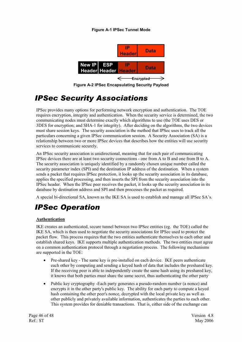
Page 46 of 48 Version 4.8Ref.: ST May 2006
Figure A-1 IPSec Tunnel Mode
Figure A-2 IPSec Encapsulating Security Payload
IPSec Security Associations IPSec provides many options for performing network encryption and authentication. The TOE requires encryption, integrity and authentication. When the security service is determined, the two communicating nodes must determine exactly which algorithms to use (the TOE uses DES or 3DES for encryption; and SHA-1 for integrity). After deciding on the algorithms, the two devices must share session keys. The security association is the method that IPSec uses to track all the particulars concerning a given IPSec communication session. A Security Association (SA) is a relationship between two or more IPSec devices that describes how the entities will use security services to communicate securely.
An IPSec security association is unidirectional, meaning that for each pair of communicating IPSec devices there are at least two security connections - one from A to B and one from B to A. The security association is uniquely identified by a randomly chosen unique number called the security parameter index (SPI) and the destination IP address of the destination. When a system sends a packet that requires IPSec protection, it looks up the security association in its database, applies the specified processing, and then inserts the SPI from the security association into the IPSec header. When the IPSec peer receives the packet, it looks up the security association in its database by destination address and SPI and then processes the packet as required.
A special bi-directional SA, known as the IKE SA is used to establish and manage all IPSec SA’s.
IPSec Operation
Authentication
IKE creates an authenticated, secure tunnel between two IPSec entities (eg. the TOE) called the IKE SA, which is then used to negotiate the security associations for IPSec used to protect the packet flow. This process requires that the two entities authenticate themselves to each other and establish shared keys. IKE supports multiple authentication methods. The two entities must agree on a common authentication protocol through a negotiation process. The following mechanisms are supported in the TOE:
�� Pre-shared key - The same key is pre-installed on each device. IKE peers authenticate each other by computing and sending a keyed hash of data that includes the preshared key. If the receiving peer is able to independently create the same hash using its preshared key, it knows that both parties must share the same secret, thus authenticating the other party
�� Public key cryptography -Each party generates a pseudo-random number (a nonce) and encrypts it in the other party's public key. The ability for each party to compute a keyed hash containing the other peer's nonce, decrypted with the local private key as well as other publicly and privately available information, authenticates the parties to each other. This system provides for deniable transactions. That is, either side of the exchange can
IPHeader
IPHeader Data
DataNew IPHeader
ESPHeader
Encrypted

Page 47 of 48 Version 4.8Ref.: ST May 2006
plausibly deny that it took part in the exchange. Currently only the RSA public key algorithm is supported
�� Digital signature -Each device digitally signs a set of data and sends it to the other party. This method is similar to the previous one, except that it provides nonrepudiation. Currently both the RSA public key algorithm and the digital signature standard (DSS) are supported.
Key Exchange
Both parties must have a shared session key in order to encrypt the IKE tunnel. The Diffie-Hellman protocol is used to agree on a common session key. The exchange is authenticated as described above to guard against "man-in-the-middle" attacks
These two steps, authentication and key exchange, create the IKE SA, a secure tunnel between the two devices. One side of the tunnel offers a set of algorithms, and the other side must then accept one of the offers or reject the entire connection. When the two sides have agreed on which algorithms to use, they must derive key material to use for IPSec with Authentication Headers (AH), ESP (Encapsulating Security Payload), or both together (the TOE uses ESP only). IPSec uses a different shared key than IKE. The IPSec shared key can be derived by using Diffie-Hellman again to ensure perfect forward secrecy, or by refreshing the shared secret derived from the original Diffie-Hellman exchange that generated the IKE SA by hashing it with pseudo-random numbers (nonces). The first method provides greater security but is slower. After this is complete, the IPSec SA is established and the packet flow is passed over the IPSec SA.
Figure A-3 – IPSec and IKE Operation
For example, in Figure B-3, Bob is trying to securely communicate with Alice. Bob sends his data (IP packets) toward Alice. When Bob's internetworking device sees the packet, it checks its security policy and realizes that the packet should be encrypted. The preconfigured security policy also says that Alice's internetworking device will be the other endpoint of the IPSec tunnel. Bob's internetworking device looks to see if it has an existing IPSec SA with Alice's internetworking device. If not, then it negotiates one using IKE. If the two internetworking devices already share an IKE SA, the IPSec SA can be quickly and immediately generated. If they do not share an IKE SA, one must first be created before negotiation of the IPSec SAs. As part of this process, the two internetworking devices exchange authentication credentials, eg. digital certificates. A certificate authority that both Bob and Alice’s internetworking devices trust must sign the certificates beforehand. When the IKE session becomes active, the two internetworking
Bob Alice
TrustedNetwork
IKE SATrustedNetwork Untrusted Network
Clear TextEncrypted Text
IPSec SA
Authenticated, Encrypted Tunnel
Router/Firewallwith IPSec TOE
Router/Firewallwith IPSec TOE

Page 48 of 48 Version 4.8Ref.: ST May 2006
devices can negotiate the IPSec SA. When the IPSec SA is set up, both internetworking devices will have agreed on an encryption algorithm (for example, DES) and an authentication algorithm (for example, SHA), and have a shared session key. Now, Bob's internetworking device can encrypt Bob's IP packet, place it into a new IPSec packet and send it to Alice's internetworking device. When Alice's internetworking device receives the IPSec packet, it looks up the IPSec SA, properly processes and unpacks the original datagram, and forwards it over to Alice. Note that this process is transparent to both Alice and Bob.