Embed Size (px)
Citation preview

SECURITYMARKING
The classified or limited status of this report applies
to each page, unless otherwise marked.Separate page printouts MUST be marked accordingly.
THIS DOCUMENT CONTAINS INFORMATION AFFECTING THE NATIONAL DEFENSE OFTHE UNITED STATES WITHIN THE MEANING OF THE ESPIONAGE LAWS, TITLE 18,U.S.C., SECTIONS 793 AND 794. THE TRANSMISSION OR THE REVELATION OFITS CONTENTS IN ANY MANNER TO AN UNAUTHORIZED PERSON IS PROHIBITED BYLAW.
NOTICE: When government or other drawings, specifications or otherdata are used for any purpose other than in connection with a defi-nitely related government procurement operation, the U. S. Governmentthereby incurs no responsibility, nor any obligation whatsoever; andthe Fact that the Government may have formulated, furnished, or in anyway supplied the said 6rawings, specifications, or other data is notto be regarded by implication or otherwise as in any manner licensingthe holder or any other person or corporation, or conveying any rightsor permission to manufacture, use or sell any patented invention thatmay in any way be related thereto.

0b.V ,
U. S. NAVY
MARINE ENGINEERING LABORATORY
Annapolis, Md.
Dedicated To PROGRESSIN MARINE ENGINEE]RING

DEDICATED TO PROGRESS IN MARINE ENGINEERING
The Marine Engineering Laboratory is charged with
the discovery of fundamental knowledge, the
development of new and unique equipment to meet
and anticipate new naval requirements, analysis
of Fleet machinery failures, and evaluation of
prototypes to insure high performance and relia-
bility in the Fleet. Dedicated to progress in
naval engineering, the Marine Engineering Lab-
oratory contributes to che technical excellence
ani superiority of the Navy today - and tomorrow.
ANY MATTERS OF COMMERCIAL CONFIDENCE INCLUDED IN
THIS REPORT MUST BE TREATED WITH DUE REGARD FOR
THE SAFEGUARDING OF PROPRIETARY INTERESTS;
THE INFORMATION CONTAINED HEREIN SHALL NOT BE
USED FOR ADVERTISING PURPOSES.
THIS REPORT HAS BEEN MACHINE ASSEMBLED. IF
ANY PAGES ARE MISSI'4G. PLEASE REQUEST FROM MEL.

FOR OFFICIAL USE ONLY
Heat Transfer Between Solids
Assignment 75 125MEL Research and Development Report 157/64
July 1965
ByR. P. Kolb
R.' P. KOLB
Approved by:
H. R. BOROSONSpecial Projects Division

MEL Repor-: 157/64
ABSTRACT
In attempts to improve thermal performanceof modules for thermoelectric generators an in-vestigation based upon a program of experimenta-tion in thermal conductance between plane solidsurfaces in both dry and lubricated contact underpressure was conducted. Surface materials wereType 6061-T6 aluminum alloy and Type RS-70 un-alloyed titanium. In some tests a 0.0027-inchmica layer was interposed between the metallicsurfaces, with dry contact. Values of conductancewere determined over a range of imposed pressuresbetween 5 and 225 pounds per square inch (psi) inmost cases, otherwise at a single pressure ofapproximately 100 psi.
Disparate results led to the conclusionthat conductance may be related to the hardnessas well as the roughness of the contacting su.faces.
Curves of conductance versus imposed pressureusually have a point of inflection at which theychange from convex to concave upward, with risingpressure. It was established that the higher thevalue of surface roughness, the lower the pressureat which the point of inflection occurs. A lubri-cated-contact aluminum/aluminum joint showed a con-ductance at 100 pqi, approximately six times thedry-contact value. A dry-contact joint with thespecified mica layer interposed showed a conductanceapproximately 1/6 the original metal-to-metal value.
Results for a variety of surface material com-binations are presented in a tabulation arranged forcomparative study.
iii

MEL Report 157/64
ADMINISTRATIVE INFORMATION
This work was performed under MEL In-House Independent ResearchProgram (SR011 01 01), Task 0401, Report Symbol BUSHIPS 3920-1.
iv

MEL Report 157/64
TABLE OF CONTENTS
Page
DISTRIBUTION LIST iiABSTRACT iiiADMINISTRATIVE INFORMATION ivINTRODUCTION ITHEORETICAL BASIS IEXPERIMENTAL DETERMINATION OF THERMAL CONDUCTANCE 2
Apparatus anp Test Setup 2Experimental Plan 3
RESULTS 4Procedures 4Values 4
DISCUSSION 6CONCLUSION 11RECOMMENDATION3 11APPENDIXES
Appendix A - Bibliography
v

MEL Report 157/64
HEAT TRANSFER BETWEEN SOLIDS
1.0 INTRODUCTION
An investigation having as its basic objective the improvement of thethermal performance of modules for thermoelectric generators was initiatedat this Laboratory during Fiscal Year 1961. Inasmuch as thermal conduct-ance at the interfaces between surfaces in contact under pressure wasan important factor in module performance, a program of experimentationwas developed to enable a study of this factor. In order to carry onthis program a contact-pressure loading apparatus was designed, constructed,and installed; and all of the study results stemmed from data obtainedthrough the use of this apparatus and the test setup of which it wr.sa part. This apparatus and the test setup have been described.5,6,7,8
During Fiscal Years 1961 and 1962, a series of contact-pressure testswere performed. Values of conductance were determined over a range ofimposed pressures between 5 and 225 psi,*utilizing a single value ofmean interface temperature (206 F), and a single value of surface finishapproximating 10 rms microinches, for several surface material combina-tions used in the construction of thermoelectric generator modules.The majority of these conductance values were between the limits of 500and 3000 Btu per (hr) (sq ft) (deg F). One of the several conclusionsestablished was that an imposed pcessure of at least 150 psi was requiredbefore a rapid increase of interface thermal conductance could be ex-pected with increabed pressure. Resulus obtained have been r4, orted indetail.8 , 10 At the conclusion of the study in June 1962, it was recom-mended that further experimentation should be undertaken, using variousmean interface temperatures, additional combinations of surface materialsfand finishes, and interfacial atmospheres other than air.A new experimental study involving thermal conductance between solid sur-faces in contact under pressure was initiated in July 1963 withLn thescope of a general investigation of interface phenomena. Tests similarto those made during Fiscal Years 1961 and 1962 were undertaken, usingspecially selected surface material combinations capable of yieldinginformation of value to the general investigation.
2.0 THEORETICAL BASIS
1"hermal conductance at the contact interface between surfaces underpressure is dependent upon several factors, the most apparent of whichare: (a) the magnitude of the imposed pressure, (b) the mean interfacetemperature, (c) the degree of surface roughness, and (d) the physicalproperties of the material or materials involved. Less obvious (but
5Superscripts refer to similarly numbered entries in the Bibltography,Appendix A.
*Abbreviations used in this text are from the GPO Style Manual, 1959,unless otherwise noted.

MEL Report 157/64
not necessarily less important) factors include: (e) the surface electronicstate, (f) the nature of the fluid filling the voids within the interface,
and (g) the waviness (degree of approach to flatness) of the contactingsurfaces. (This last factor is not to be confused with surface roughnesswhich is a matter of finish rather than shape.) A complete and accurate
determination of interface conductanvp depends upon a consideration of all
of these factors simultaneously.
Theoretical and experimental studies by various investigators have concen-trated on those factors which can be controlled and which at the same timeexert a predominant influence on conductance values, especially when thesevalues are to be used in engineering design. Despite the existence of a
substantial body of literature on interface thermal conductance, no con-sistent and comprehensive theory has as yet been advanced; however, muchexcellent published material in various study areas may, by synthesis,produce such a theory. A suitable mathematical model may provide thebasis for a comprehensive theory.
Theoretical analyses 2,3,12 have dealt with the effects of imposed pressure,surface roughness, and interfacial fluids. The influence of other factorsmentioned abcve should be studied in depth, looking toward the formulationof a comprehensive theory.
3.0 'EXPERIMENTAL DETERMINATION OF THERMAL CONDUCTANCE
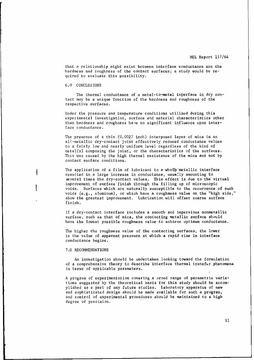
3.1 Apparatus and Test Setup. A sectional elevation of the contact-"
pressure loading apparatus which formed the central component of thetest setup is shown in Figure 1. This apparatus has been described
fully,5 ,6 with accompanying illustrations. The primary feature of this
apparatus is the arrangement of upper and lower pedestals between whose
contact surfaces the interface is formed. These descriptions set forth
the physical features of the pedestals, together with the arrangement
of inserted thermocouple.s. Center is a point; it can't be "iround"
anything.
3.1.1 Since the inception of the project in Fiscal Year 1961, the pedes-
tal materials utilized in the several test programs have included medium-
carbon plain steel, ]ype 316 stainless steel, electrolytic tough-pitch
copper, Armco ingot iron, Type 6061-T6 aluminum alloy, and titanium.
3.1.2 The test setup is illustrated in Figure 2 where the encemble is
shown mounted upon the table in the foreground. The contact-pressure
loading apparatus, with baseplate and peripheral pedestal surfaces fully
insulated, is at the left end of the table with the electrical heater
controls adjacent to it. Wires from 18 thermocouples in the two contact-
ing pedestals lead to the precision potentiometer at the right end of
the table through a cold-junction device and a selector switch. Imposed
pressure may be varied by changing the number of calibrated weights on
the suspended platform which hangs from the yoke of the apparatus. A
Variac in the wain heater power-supply line enabled a continuous adjust-
ment of the rate of heat input to the lower pedestal from baseplate source
to maintain as nearly as possible a selected constant temperature at a
particular thermocouple in the lowest row of the lower pedestal.
2

MEL Report 157/64
ALUMINUM RADIA FOR -LOADING YOKE/
LOAD
INSULATION
S. --UPPER PEDESTALANNULAR CONTACT.....
INTERFACE r- THERMOCOUPLES
THREE VERTICAL ROWSIN EACH PEDESTAL
INSULATION-------- LWER PEDESTAL
ASBESTOS SHEET -- CARTRIDGE HEATERS
SBENCH
Figure 1Sectional Elevation of MEL
Contact-Pressure Loading Apparatus
3.2 Experimental Plan.
3.2.1 Surface material selected for the current test program includedType 6061-T6 aluminum alloy, and Type RS-70 unalloyed titanium. Threedifferent arrangements cE aluminum alloy joints were tested. The firstconsisted of surfaces in direct dry contact, the second of surfacesin direct lubricated contact, and the third of surfaces in dry contactwith an interposed mica layer. Titanium joincs consisted of a pair ofsurfaces, first in direct dry contact, and second in dry contact withan interposed mica layer. The aluminum/aluminum lubricated-nontactjoint was tested at a single imposed pressure of 100 psi and chetitanium/mica/titanium joint at a single pressure of 100.6 psi.
3

MEL Report 157/64
3.2.2 For each test, data were obtained using procedures similar tothose previously described. 5 ,6 Data points for the full-range testswere establiohed over a range of imposed pressures* between approxi-mately 5 and 225 psi with point-to-point intervals not larger than 25psi. The exact values of imposed pressure used for plotting resultswere dependent upon the weight of the particular upper pedestal in,se, since this weight formed part of the total force applied at theinterface.
3.2.3 In accordance with an original decision to simplify the experi-mental procedure, all tests were performed in ordinary atmosphere withheat dissipation from the apparatus radiator by natural convection.Pedestal contact surfaces were machined to the various values of finish,in terms of rms microinches, stated subsequently in this report; how-ever, no cousideration was given to possible surface waviness.
4.0 RESULTS
4.1 Procedures. For each test, proceddres identical with those pre-viously described 10 were used to compute results. Data were firstused to plot temperature gradient lines (average observed temperatureat thermocouple locations versus thermocouple distances from contactinterface) for each pedestal of the pair, and the extension of theselines past the interface (zero distance) location on the graph enabledthe determination of the temperature drop between the contactingsurfaces. As before, the application of the indicated lower-pedestaltemperature gradient in the equation for steady-state conductioneffected a solution for the thermal flux entering the pedestal fromthe heat source. The heat flux crossing the interface between thepedestals was then determined by subtracting from the calculated in-put the computed loss of heat in a radial direction from the thermo- Icouple zone within the lower pedestal, through the metal, the insula-tion, the jacket, and the air film to the surrounding atmosphere.
4.2 Values. The values of thermal conductance, h, as a function ofapparent pressure are presented in this report for the several surfacecombinations tested. The curves portraying this relationship werederived from preliminary graphs of log-h versus log-pressure which had,in turn, been established by "fairing" through the several patternsof computed points.
* Throughout the descriptive portions of this report, the term "imposedpressure" has been used to denote the ratio of applied force tosuperficial surface contact area. This may be designated more preciselyas "apparent pressure;" and this quantity is practically always smaller(and often much smaller) than the real surface contact pressure. Themagnitude of the real pressure is a function of the roughness and wavi-ness of the surfaces involved inasmuch as these factors determine theextent of the actual solid-to-solid contact at the interface.
4

MEL Report 157/64
rd
0
U 04
rir
4*H4)
()0
4~J
zM0
4J
44
-4-r5

ML Report 157/64
4.2.1 'Me mica layer, which was interposed between the metallicbounding surfaces during some tests, took the form of a washer havingsuitable inner and outer diameters and a thickness of 0.0027 inch.In the computations for conductance, the thermal conductivity of micatransmitting heat normal to its natural cleavage planes was taken froman authoritative source to be 0.25 Btu per (hr) (ft) (deg. F).Curves showing the variation of thermal conductance with apparentpressure for the full-range dry-contact tests are portrayed in Figures3 through 6.
4.2.2 At the single apparent pressure of 100.6 psi and a mean inter-face temperature of 206 F, the overall thermal conductance of thetitanium/ mica/titanium joint was 520 Btu per (hr) (q ft) (deg F), forthe path between the enclosing metal surfaces. At the same apparentpressure and interface temperature, the value of conductance for eachtitanium/mica interface was 1910 Btu per (hr) (sq ft) (deg F). Themetallic surfaces were finished to roughnesses of 4.2 and 5.4 rmsmicroinches.
4.2.3 The lubricated-contact test of an aluminum/aluminum joint wasperformed after the metallic surfaces had been coated with the thinnestpossible film of silicone grease. At the single apparent pressure of100 psi and a mean interface temperature of 206 F, the thermal conduct-ance was 19950 Btu per (hr) (sq ft) (deg F). The surfaces werefinished to roughnesses of 15 and 17 rms microinches.
5.0 DISCUSSION
The final results portrayed in Figures 3 through 6 may be comparedwith those for similar tests with other surface material combinations,as previously shown in Figure 1 of the 1962 Progress Report8 andFigure 4 of a later report of investigation. 10 Especially notable isthe curve of Figure 3 which has an inflection at approximately 55 psi,whereas the curves for Tests 4, 8A, and 12A of Figure I of theProgress Report 8 have an inflection at approximately 125 psi. Thisshift of the inflection point toward a lower pressure is attributedto the rougher surface finish of the aluminum/aluminum joint as com-pared with the others cited above.
Past and present results for both single-pressure and full-range testswere compared at an apparent pressure of 100 psi. This comparisonis set forth in Table I where the thermal conductance values for anumber of selected surface combinations are recorded, each group beinparranged in ithe order of increasing magnitude. Past results listedin Table 1 were reported originally in 1962.8,10
6

MEL Report 157/64
USN MARINE ENGINEERING LABORATORY
10,000
8,000
7,000 L
-
0
-, 600--
.1-4. .= 500 -
0z LS 400 - - - - - - - -
= z"
5,000 - /-o 30I VALUES ADJUSTED TO A MEAN
z - INTERFACE TEMPERATURE OF 2c6 F.-j AVERAGE METALLIC SURFACE FIN-
4,000ISS, 15 AND 17 RMS MICRO-z oINCHEs.S/20
( ~~~3000 2 - -- I10 50 10 50 50 100 150 200 250
2,000 APPARENT PRESSURE , psi
VALUES ADJUSTED TO A MEAN INTER-FACE TEMPERATURE OF 206 F.
1,000 AVERAGE METALLIC SURFACE FINISHES,15 AND 17 FMS AIICROINCHES.
0-- 1111 h E iiFigure 40 50 100 50 200 250 Variation of Thermal Conductance
APPARENT PRESSURE, Pwith Apparent Pressure for a
Dry-Contact Joint HavingFigure 3 Bounding Surfaces of Type 6061-T6
Aluminum and an InterposedVariation of Thermal Conductance Mica Layerwith Apparent Pressure for anInterface Having Type 6061-T6
Aluminum Surfaces in Dry Contact
7

EL Report 157/64
USN MARINE ENGINEERING LABORATORY
3500
C3,000
g,500 2 iFigure 5
- ., - Variation of Thermal
2P000 _ ___ ___ Conductance with Apparent___ZI__ l Pressure for a Type 6061-T6
1500 I/I j! K Aluminum/Mica Interfacein Dry Contact
0 ~~VALUES ADJUSTED TO0 A MEANITS
____ ACF TEMPERATURE OF -C6 F.
- o I:E lOGO - ~ AVEPAGE METALLLC SURFACF FINIS~IMS,
15 AND0 17 lOIS MICROISClSES.
500
0 50 100 150 200 250
APPARENT PRESSURE psi
900 ____
800 - - I .
U. I
IDFigure 6 7 ,
Variation of Thermal 600 _
Conductance with Apparent IaPressure for an Interface 0
Having Titanium Surfaces 500
in Dry ContactS i ' ,, - , A!,jT ,In , , .
400 - l" * A I %I xT I" I
F l I' ! , A'-'1 o -- S- T 'S--- -- .
200L 10 50 100 150 :00 2Si
APPARENT PRESSURE
8

S ,I
MEL Report 157/64
Table I
Values of Thermal Conductance, in Btu per (Hr) (Sq Ft) (Deg F), at a MeanInterface Temperature of 206 F and an Apparent Pressure of 100 PSI
For Various Surface Material Combinations
Group 1Metal-to-Metal(Dry Contact)
Titanium/Titanium 577Stainless Steel/Copper 1198Stainless Steel/Stainless Steel 1275Stainless Steel/Armco Ingot Iron 1480Carbon Steel/Carbon Steel 1720Aluminum/Stainless Steel 2080Aluminum/Aluminum 3300
Group 2Metal-Mica-Metal (Dry Contact)
Stainless Steel/Mica/Copper 520Titanium/Mica/Titanium 520Aluminum/Mica/Aluminum 554
Group 3Metal-to-Mics (Dry Contact)
Stainless Steel/Mica 1905Titanium/Mica 1910Aluminum/Mica 2215
Group 4Metal-to-Metal (Lubricated Contact)
Stainless Steel/Copper 2620Aluminum/Stainless Steel 5480Aluminum/Aluminum 19950
An inspection of Table 1 indicates that the metal-to-metal dry-contactjoints (Group 1) presented an orderly progression of conductance valuesfrom titanium/titanium on the low end to aluminum/aluminum on the highend of the scale.

MLL Report 157/64
the overall conductance of dry-contact joints was substantially decreasedwhen a 0.0027-inch mica layer was interposed between the metal surfaces(fable 1, Group 2). Although the conductance of this layer alone wascomparatively high ([110 Btu per (hr) (sq ft) (deg F)), its presenceresulted in a thermal circuit containing three resistances in series, withattendant reduction in overall conductance to a depreciated value whichwas nearly uniform regardless of the metallic surfaces involved.
Yhe metal-to-mica interfaces (Group 3) exhibited fairlyhigh conductancevakies as well as significant variations from the figures presented forthe related metallic surfaces of Group 1. The conductance of titanium/mica was more than three times that of titanium/titantium whereas thatof aluminum/mica was only 2/3 that of aluminum/aluminum. Analysis indi-cated that these peculiar conditions are related to surface roughness.In the titanium/mica joint, the titanium surface with a roughness of only4.2 rms microinches contiguous to the very smooth (nonserrated) micasurface resulted in an interface having fewer voids and greater contactarea than the titanium/titanium joint, with resulting higher conductance.In the aluminum/mica joint, the rougher aluminum surface (15 rms micro-inches) contained many voids filled with high-resistance air trapped behindthe smooth contacting mica, whereas in the aluminum/aluminum joint, mostof these voids were filled by interpenetration with the serrations of thetwo surfaces, the result being a higher conductance in the all-metallicjoirt.
L bricatod-contact joints were produced by coating each of the surfacesinvolved with the thinnest possible film of silicone grease which ex-pelled the air from all voids and left these pockets filled with lubri-cant. A substantial increase in interface conductance resulted, asindicated by a comparison of the joints listed in Table 1, Group 4 withthe related joints in.Group 1. The relative increase in conductance wasexpecially pronvunced in the case of surfaces having higher roughnessvalues (e.g., aluminum/aluminum) where the voids are deeper and morenumerous.
An extended study was made to determine a possible functionsl relationshipbetween thermal conductance and various physical characteristics of con-tact surfaces and surface materials, using experimentally establishedinformation as a basis. The group of metal-to-metal dry-contact jointsshcwn in Table I, together with their stated values of conductance atthe specified conditions of temperature and pressure, were used in thisstudy. Physical characteristics investigated included the yield strengthof the joint materials and the hardness and roughness of the contactsurfaces. Other characteristics considered were determined to be unre-lated to conductance.
The yield strength of the "weaker," or "indented," material which hasbeen cited by some investigators as a factor in interface conductance,was found to be of no significance for the range of test pressures uti-lized in the MEL program. Substantially higher imposed pressures wouldbe needed to produce significant surface indentation, with consequentreduction of voids and increase of conductance. It appeared however,
10
MEL Report 157/64
that a relationship might exist between interface conductance ana thehardness and roughness of the contact surfaces; a study would be re-quired to evaluate this possibility.
6.0 CONCLUSIONS
The thermal conductance of a metal-to-metal interface in dry con-tact may be a unique function of the hardness and roughness of therespective surfaces.
Under the pressure and temperature conditions utilized during thisexperimental investigation, surface and material characteristics otherthan hardness and roughness haie no significant influence upon inter-face conductance.
The presence of a thin (0.0027 inch) interposed layer of mica in anall-metallic dry-contact joint effectively reduced conductance valuiesto a fairly low and nearly uniform level regardless of the kind ofmetal(s) composing the joint, or the characteristics of the surfaces.This was caused by the high thermal resistance of the mica and not bycontact surface conditions.
The application of a film of lubricant to a wholly'metallic interfaceresulted in a large increase in conductance, usually amounting toseveral times the dry-contact values. This effect is due to the virtualimprovement of surface finish through the filling up of microscopicvoids. Surfaces which are naturally susceptible to the occurrence of suchvoids (e.g., aluminum), or which have a roughness value on the "high side,"show the greatest improvement. Lubrication will offset coarse surfacefinish.
if a dry-contact interface includes a smooth and impervious nonmetallicsurface, such as that of mica, the contacting metallic surface shouldhave the lowest possible roughness value to achieve optimum conductance.
The higher the roughness value of the contacting surfaces, the loweris the value of apparent pressure at which a rapid rise in interfaceconductance begins.
7.0 RECOMNENDATIONS
An investigation should be undertaken looking toward the formulationof a comprehensive theory to describe interface thermal transfer phenomenain terms of applicable parameters.
A program of experimentation covering a oroad range of parametric varia-tions suggested by the theoretical basis for this study should be accom-plished as a part of any future studies. Laboratory apparatus of newand sophisticated design should be made available for such a program,and control of experimental procedures should be maintained to a highdegree of precision.
11
MEL Report 157/64
Appendix A
BIBLIOGRAPHY
I - Brunot, A. W., and Buckland, F. F., "Thermal Contact Resistanceof Laminated and Machined Joints," Trans ASME, Vol. 71, 1949,p 253
2 - Cetinkale, T. N., and Fishenden, M., "Thermal Conductance ofMetal Surfaces in Contact," International Conference on HeatTransfer, The Institution of Mechanical Engineers, London, 1951
3 - Fenech, H., and Rohsenow, W. M., "Prediction of Thermal Con-ductance of Metallic Surfaces in Contact," Jl of Heat Transfer(ASME), Feb 1963, p 19
4 - Kolb, R. P., "Thermoelectric Generator Design Study," NAVENGRXSTASemiannual Progress Report, Fundamental Scientific Program,Jul-Dec 1960, pp. 3-9
5 - Kolb, R. P., "Thermoelectric Generator Design Study," NAVENGRXSTASemiannual Progress Report, Fundamental Scientific Program,Jan-Jun 1961, pp. 5-8
6 - Kolb, R. P., "Thermoelectric Generator Design Studies," NAVENGRXSTAR & D Rept 710513, 8 Aug 1961
7 - Kolb, R. P., "Thermoelectric Generator Design Study," NAVENGRXSTASemiannual Progress Report, Fundamental Scientific Program,Jul-Dec 1961, pp. 8-13 '
8 - Kolb, R. P., "Thermoelectric Generat6r Design Study," NAVENGRXSTASemiannual Progress Report, Fundamental Scientific Program,Jan-Jun 1962, pp. 5-9
9 - Kolb, R. P., "Thermoeleztric Generator Design Study," NAVENGRXSTASemiannual Progress Report, In-House Independent Research Program,,Jul-De4 1962, p. 5
10 - Kolb, R. P., "Thermoelectric Generator Design Study," NAVENGRXSTAR & D Rept 84 513, 5 Mar 1963
11 - Kolb, R. P., "Heat Transfer Phenomena Between Solids," MELSemiannual Progress Report, In-House Independent Research Program,Jul-Dec 1963, pp. 5-9
12 - Rogers, G. F. C., "Heat Transfer at the Interface of DissimilarMetals," International Jl of Heat and Mass Transfer, Vol. 2, 1961p. 150
13 - Weills, N. D., and Ryder, E. A., "Thermal Resistance Measurementsof Joints Formed Between Stationary Metal Surfaces," Trans ASNE,Vol.71, 1949, p. 259

Security Classification UnclassifiedDOCUMENT CONTROL DATA R&D
(Security Classification of title body of abstract and indexing annotation must be entered when the overall report is classified)
I ORIGINATIN G ACTIVITY (Corporate author) 2a RCPORT SECURITY C LASStFICA' IONU. S. Navy Marine Engineering Laboratory UnclassifiedAnnapolis, Md. 21402 2b GROUP
3 REPORT TITLE
H{eat Transfer Between Solids
4 OESCRIPTIVE NO'ES (Type of report and inclusive date@)
S AUTHOR(S) (Last name, first name, initial)
Kolb, Robert P.
6 REPORT DATE 17a TOTA NO OF PAGEV 7b NO OF REPS
July 1965 12 138 CONTRACT OR GRANT NO 98 ORIGINATOR'S REPORT NUMBER(S)
b PROJECT NO S-R011 01 01 157/64Task 0401
c 9b. OTHER REPORT NO(S) (Any other numbers that maybe anal adthis raport)
d Assigt 75 125
10 AVA ILABILITY/LIMITATION NOTICES
Qualified requesters may obtain copies of this report from DDC.
II SUPPLEMENTARY NOTES 12. SPONSORING MILITARY ACTVITY
NAVSHIPS
13 ABSTRACT In attempts to improve thermal performance. of modules for thermoelectric
generators an investigation based upon a program of experimentation in thermalconductance between plane solid surfaces in both dry and lubricated contact underpressure was conducted. Surface materials were Type 6061-T6 aluminum alloy andType RS-70 unalloyed titanium. In some tests a 0.0027-inch mica layer was inter-posed between the metallic surfaces, with dry contact. Values of conductancewere determined over a range of imposed pressures between 5 and 225 pounds persquare inch (psi) in most cases, otherwise at a single pressure of approximately100 psi. Disparate results led to the conclusion that conductance may be re-lated to the hardness as well as the roughness of the contacting surfaces. Curvesof conductance versus imposed pressure usually have a point of inflection atwhich they change from convex to concave upward, with the rising pressure. It wasestablished that the higher the value of surface roughness, the lower the pressureat which the point of inflection occurs. A lubricated-contact aluminum/aluminumjoint showed a conductance at 100 psi, approximately six times the dry-contactvalue. A dry-contact joint with the specified mica layer interposed showed aconductance approximately 1/6 the original metal-to-metal value. Results fora variety of surface material combinations are presented in a tabulation ar-ranged for comparative study.
(Author)
D-D I 1473 Unclassified
Security Classification

Security Classification Unclassified14 LINK A LINK B LINK CKEY WORWS E T ROLE WT ROLE WT
lerrmoelectric generatorsThermal conductdnceHeat transferGenerator niodules
INSTRUCTIONS
I. ORIGINATING ACTIVITY: Enter the name and address imposed by security classification, using standard statementsof the contractor, subcontractor, grantee, Department of De- sucn as:fense activity or other organization (corporate author) issuing (1) "Qualified re-uesters may obtain copies of thisthe report. report from DDC."2a. REPORT SECUITY CLASSIFICATION: Enter the over- (2) "Foreign announcement and dissemination of thisall security classification of the report. Indicate whether report anno t adie""Restricted Data" is included. Marking is to be in accord- report by DDC is not authorized."ance with appropriate security regulations. (3) "U. S. Government agencies may obtain copies ofthis report directly from DDC. Other qualified DDC2b. GROUP: Automatic downgrading is specified in DoD Di- user lret troughrective 5200. 10 and Armed Forces Industrial Manual. Enter users shall request throughthe group number. Also, when applicable, show that optional " -markings have been used for Group 3 and Group 4 as author- (4) "U. S. military agencies may obtain copies of thisized. report directly from DDC. Other qualified users
3. REPORT TITLE: Enter the complete report title in &ll shall request throughcapital letters, T,,.es In all caser should be unclassified.If a meaningful title cannot be selected without classifica-tion, show title classification in all capitals in parenthesis (5) "All distribution of this report is controlled. Qual-immediately following the title. ified DDC users shall request through4. DESCRIPTIVE NOTES. If appropriate, enter the type of __"_
report, e.g., interim, progress, summary, annual, or final. If the report has been furnished to the Office of TechnicalGive the inclusive dates when a specific reporting period is Services, Department of Commerce, for sale to the public, indi-covered, cate this fact and enter the price, if known.5. AUTHOR(S): Enter the name(s) of author(s) as shown on 11. SUPPLEMENTARY NOTES: Use for additional explana-or in the report. Entet tast name. first name, middle Initial, tory notes.If military, show rank and branch of service. The name ofthe principal adthor is an absolute minimum requirement. 12. SPONSORING MILITARY ACTIVITY: Enter the name of
the departmental project office or laboratory sponsoring (pay6. REPORT DAT_ Enter the date of the report as day, mng for) the research and development. Include address.month, year; or month, year. If more than one date appearson the report, use date of publication. 13. ABSTRACT: Enter an abstract giving a brief and factual
summary of the document indicative of the report, even though7a. TOTAL NUMBER OF PAGES: The total page count it may also appear elsewhere in the body of the technical re-should follow normal pagination procedures, i.e., enter the port. If additional space is required, a continuation sheet shallnumber of pages containing information, be attached.7b. NUMBER OF REFERENCES. Enter the total number of It is highly desirable that the abstract of classified reportsreferences cited in the report. be unc!assified. Each paragraph of the abstract shall end withBa. CONTRACT OR GRANT NUMBER: If appropriate, enter an indication of the military security classification of the in-the applicable number of the contract or grant under which formation in the paragraph, represented as (TS), (S), (C), or (U)the report was written. There is no limitation on the length of the abstract. How-8b, 8c, & 8d. PROJECT NUMBER: Enter the appropriate ever, the suggested length is from 150 to 225 words.military department identification, such as project number,subproject number, system numbers, task number, etc. 14. KEY WORDS: Key words are technically meaningful termsor short phrases that characterize a report and may be used as9a. ORIGINATOR'S REPORT NUMBER(S): Enter the offi- index entries for cataloging the report. Key words must becial report nu nber by which the documpnt will be identified selected so that no security classification is required. Identi-and controlled by the originating activity. This number must fiers, such as equipment model designation, trade name, militarybe unique to this report. project code name, geographic location, may be used as key9b. OTHER REPORT NUMBER(S): If the report has been words but will be followed by an indication of technical con-assigned any other report numbers (either by the originator text. The assignment of links, rules, and weights is optional.or by the sponsor), also enter this number(s).10. AVAILABILITY/LIMITATION NOTICES Enter any lira-itations on further dissemination of the report, other than those
DD tJANO. 1473 (BACK) Unclassified
Security Classification

U) 41iI
t4- I 1,- 0 14 U) 0 4 -- >4
41 J 44 k u 0 :5 m r -4 0O -4 4
I~~~~d li w W(O PO4(1(1) 144 V) CO 44 = C Z W t> 4. U -
-V (1 4 ( r V 0 (n U ...
(.) 4 -4 di
-4 rn W V .W4 O d (U) )0. u ) 0 4-, O-4~ ,4 C) z 4 ud -
-I 0C di C:O (0 -4 4jtn w w 00 M U
0 4 0 B 0)4- Wi 0i- s,)~ 41 m - i 44 4)
.I > >$ 00.--4 Q.4. di 1 Ai $ 41 O-
- Ab Zd di-Cd Qd CdIJ:U *-,4 Z .o
4O 44iJ~d Jp4 -1
Q) 0 0r 1Z w 4 W4cl0r C ) U) 4-J -~CL' * *di (1) Cd W ObO>4-'
441C a V)~t I 4 E LU) P M 1) ) 0 -r. 4 - 4 4111
di -, 001W 41r) -4 - '0 3 O
+- J4 Jk -0 U zr )- a) 0U (0 CddM -dd V) 0 0) C a 4E q 4 -0 - - $ ) )ZO4 0 -4 -1 0 4J C
cr a w (~U P ) " LJQ P to0 C DUCo00 dC
CZ ~ 4- *-I ; 0 P. 0 .41 ) ~ 41 ~0 > 0q . 304J T0 44 C04-i .0 p - )H OU W i0.. O 4d 4 Cd 0)f wuCdA 40
~dU0 U - 0 V4. r () 1r-4U() 0 4J ~ d i 00 Q 4-iS
C d . 4 1- > = -
w 4i 0 z U J4 C- U ': d -U 04
(1) ~ ~ ~ 0. 10 V) m ) 0 - J 04 )- i4 " , 41
C) f 4Od0 UUi - d(L )t - 0 .- 1- Ci di .i 3 0c 4 t
-4 ~ ~ ~ ~ ~ ~ *~ 410 4 04 J - ) Q W u - > 4 10 Dr 4J W
f-i 4J% 4W 4 $ " :- Z E :1 04 Cd - i- w 4.141 a)- D
0 40 CJQ -4 "0 Q (L) wR 0 rCd *-4-- (0 1 -(1 4w ~ ~ ~ 0 0U) CA C4 -j rpU 4 W ) 0 > 0 (db
W 4-I rX4 U) a)i~iCd W 0
(n a r %4-0 U) 0d In- H O ) 0 .C: 44 b ()U * -4
41C ) Zd 0C.) en 4jQ ) 0 . r-A$ 0 di4J 2 0 (
*00~di.~ 41- 4)ll - o ) ALW( 0) 41.W u 1 z 0n a) " 40-Cd r4 :3 44 0)4i- -'~ i 0 d > U) 4J ) r4 r b
O -I 0 () 0- 01 a)4 I' 9)1JJJ' Cd-' 0 U)0.0 4J
-I C4 r r I - 4 W - D Jm 0 i z-4. ul) U) a-J a)l Od Q i (I -A
;7__4 _-4 P __________P._z41 Cdr > uU0 ) b V. 0> jd44
0 i (1 ,40 0 nW j 0 w P.4X0
U) -:4 ~4 s,~C 0 0 -40
C 0 44U(1 ~C di '0 'D ~ 4.l 4idi" Q)4-3
W 4
C'-4' Q ( O W 0~ Z . 4. U O d dO )14 -4 *.-4 *i 4 C oa ;Na
4-)j .1 a -4-4 diW l)4. 4 0dUM,) 0>dC' diW WJ 4~4J C 0 04 L 4 z: jc d4
:4 C , X ~0 0. 4-j04 U 1:4 W .44 C i- 1.0 I.. U) 0- -0 4J-4 4J 0 --
o i W I. - ~ ~ j,4 Sid id.~ '-
41 .. i>O IO 40 LW4- di d CO 4 w 04.1 -- W S-
- ( 44 Z/T-~ LI0i. 0-- 0 di 0- -A)~ r-~. 4 U I S -4 iP-4. 0d -H $4 i-ud dL ~ ,4 d44 U) 0C -4 (1 >
04( - *.4* -4 C0 -aid 'n ) 0 0
W I'C w.4-U 4) () . >p.c 0 Cd a -0'
d)WEAi 4 C: CaU)d0 C04: W~ 0 ) 4J U '0 -,4
lu w 0 4 to Cd C~40 0 Jd U) 4 0 0W 4 *)**s W4 4 -
,4 U)4 (1O)di~ 0.0C .0-- d 3O> Q 4-i 0 CXd .4(-4 -4C W- -W1 Cd 4J1 t 0I Q) 0~ O U> r, '4 4 u 4
0 0 4 0.Os1 a0MdW 4CdCiCOS-4U) O~dd~~ 0O' C:l~~~~~~~l 44 1UOt~ >C4i)~d4i -4 S-a,0 0r 0v
-0fl di pC~ WnO. OoaU 04 (- ) 0 4Q)~ 0) 4-iO. 4) H-S .J3Q 444i' C 4J 4 r :4
0 ( r 0 04)- biW wdd-'- 0f -4-i- 0 a).. (-C ., 4J 4-J C: (L W 4-4 rn cf
li-al-I w4 00-0 0-. PO Cid0 41-4
cd0 A -J) 4-r0dP4 0)--)~ 4M~ .) 0 V) 4) to t 44;)N U*4
0d) D; 1.di ,Cd0 IU44'* 00 -:1:C OJ 00 d 41 n)p E5q jUr4E
0 -a. U4 dC", I. tw0 -n0 4J)4
rn4 ()C 4 J 4W> fldz tU 0 0. f U O 0 x