Embed Size (px)
Citation preview

Abstract — Nowadays, Wireless Sensors Networks (WSN)
are the most important components in the booming Internet
of Things (IoT). Given the use of WSN in systems that are part
of the critical infrastructure of a country, the primary task is
continuous authentication of WSN nodes. This paper describes
how to use the Trusted Platform Module (TPM) to authenticate
sensors which create a sensors’ domain in WSN. A model
of wireless sensor network as well as operations associated with
authentication in the sensors domain are presented.
Additionally, an implementation of selected operations in
the sensors domain is described; this includes: the master node
initialization, slave nodes registration, and data transfer
between them. Testing environment including the construction
of nodes equipped with the TPM is described. The solution
developed by the authors of the paper is only a partial
realization of a broader concept of authentication in WSNs
supported by the TPM.
I. INTRODUCTION
n the age of common electronic communications security
plays an increasingly important role. This applies to a
wide range of aspects of everyday life starting from
household to complex control systems. Mainly results used
for communication generally available network in order to
minimize costs, increase the efficiency of data processing, as
well as reducing access time to data. In this issue also part of
Wireless Sensor Networks WSNs networks that have a wide
application.
A WSN can be defined as a group of independent nodes,
communicating wirelessly over limited frequency and
bandwidth [1]. Execution of the tasks by the WSNs
compared to typical sensor networks depends on dense
deployment and coordination of sensors. Only the level
of technology and human imagination are a limitation in
applying of WSNs in any field of life. In a certain
implementations of WSNs (e.g. in military areas) an
ensuring of adequate level of security is required. In various
implementations of WSNs confidentiality and reliability
play an important role. A suitable level of confidentiality
and reliability of data as well as security level against attacks
can be achieved by applying a data encryption and an
authentication of the nodes.
An attempt to design a secure WSN requires that
the security components should be included into each node
in the system. Any component of a network implemented
without any security could easily become a point of attack.
This means that security must permeate every aspect
of design applications of wireless sensor networks that
collect or disseminate sensitive information. Such solutions
require a high level of safety.
Considering the military, police, emergency services
or others, secrecy is part of their nature, so the data
(sensed/disseminated/stored) are required to remain
confidential. This is critical to the successful operation
of a military, police, emergency applications. Enemy/threat
tracking and targeting are among the most useful
applications of wireless sensor networking.
Usually, the wireless sensor networks (WSNs) consist
of large number of ultra-small, low-power and inexpensive
wireless sensor nodes with sensing, computing and
communication capabilities [2], [3]. It is assumed that such
sensors must operate unattended for long periods of time
such as several months or even years. In military
applications, where the most important element is the safety,
the times of maintenance-free operation are not most
important, more that, often the life of the sensor will
be limited to, for example, a few hours or days.
In consequence, the power consumption may not be
a critical parameter.
Security mechanisms deployed in WSNs should involve
collaborations among the nodes due to the decentralized
nature of the networks and absence of any infrastructure.
The situation becomes critical when the nodes are equipped
with cryptographic materials such as keys and other
important data in the sensor nodes. Moreover, enemies/
adversaries can introduce fake nodes similar to the nodes
available in the network which further leave the sensor
nodes as un-trusted entities.
A characteristic property of WSN are limited resources
of nodes creating the network. Attempting to implement
an additional functions in such network is always a big
challenge for designers of such a network. Introduction to
WSN of any security mechanism is also the subject to this
rule. Therefore, scientists have tried to offer various network
security solutions tailored to the limited resources WSN.
These proposals includes: secure and efficient routing
protocols [1], [4], secure data aggregation protocols [5], [6],
I
Securing transmissions between nodes of WSN using TPM
Janusz Furtak
Military University of Technology
ul. Kaliskiego 2,
00-908 Warszawa, Poland
Email: [email protected]
Jan Chudzikiewicz Military University of Technology
ul. Kaliskiego 2,
00-908 Warszawa, Poland
Email: [email protected]
Proceedings of the Federated Conference on
Computer Science and Information Systems pp. 1059–1068
DOI: 10.15439/2015F144
ACSIS, Vol. 5
978-83-60810-66-8/$25.00 c©2015, IEEE 1059

[7], [8] and additional security mechanisms supported
by Trusted Platform Module (TPM) [9], [10], [11], [12],
[13], [14], [15]
A characteristic property of WSN are limited resources of
nodes creating the network. Attempting to implement an
additional functions in such network is always a big
challenge for designers of such a network. Introduction to
WSN of any security mechanism is also the subject to this
rule. Therefore, scientists have tried to offer various network
security solutions tailored to the limited resources WSN.
These proposals includes: secure and efficient routing
protocols [4], [1], secure data aggregation protocols [5], [6],
[7], [8] and additional security mechanisms supported by
Trusted Platform Module (TPM) [9], [10], [11], [12], [13],
[14], [15].
Usually, the sensors used in military applications should
be capable of being used for a relatively short period of time
(e.g. several hours or days rather than months or years).The
time is limited to the execution of a single task. In such
situations typically, there is no restriction on energy
consumption by sensor. Examples of such applications are
shown in Fig. 1.
Fig. 1 WSN in military applications
Considering the above, the secure method of transmitting
and storing data in WSNs is proposed in the paper.
The Trusted Platform Module (TPM) is the basis
of the presented method. A TPM is used for secure storing
the necessary data to authenticate the nodes, and generate
symmetric keys, and asymmetric keys (private/public).
The solution presented in the paper uses the concept
of authentication in WSNs using TPM developed by
the authors of the paper and described in detail in [13].
In the second section proposed architecture of WSNs, and
basic definitions are presented. The basic data of each node
are stored in every nodes (type and scope of stored data
depends on the role they played in the network e.g. domain
master (node M), and slave (node S)). In the section
the basic data structures used in the nodes are also defined.
The third section shortly describes procedures to ensure
proper authentication of sensors in domain and correct data
transfer between sensors and in detail describes a certain
operations in sensors’ domain. In the fourth section a few
experiments with selected operations in sensors domain and
obtained results are presented. Finally, a few concluding
remarks are presented.
II. THE MODEL OF WIRELESS SENSOR NETWORK WITH
AUTHENTICATION1
In the domain of sensors there are two authorities.
The first is the node (Data Collector) which is the recipient
of the data emitted by the domain sensors. The node which
manages the Root of trust is the second authority. The Root
of trust is to be used to authenticate all sensors involved
in the exchange of data between elements of the domain
of sensors. The second authority is to act as a master
of domain and will be called the node M. The presented
concept assumes that both the role of the recipient of data
from the sensors (i.e. Data Collector) and the role
of the master of domain plays the same node.
In the sensors' domain is exactly the one node that acts as
the domain master (node M). To this domain belong sensors
of type slave (nodes S), which are registered by the node M.
Nodes S are the source of data. Node S is initiated and
authenticated by node M of domain. Node M stores the root
trust of sensors' domain. The sensors' domain structure
is shown in Fig. 2.
Fig. 2 The structure of sensors’ domain
In the domain may be designated nodes acting as backups
masters (replicas of master - rM). Such a node may
be a S node after the establishment the role rM for him,
on condition that its hardware and software resources
provide this capability. In the domain may be no node type
rM (this is not recommended), but there may be a few such
nodes. The task of node rM is to store a copy of the root
of trust from the node M of domain.
From the viewpoint of authentication procedures nodes M
and rM for nodes S are the same. Node rM can become
a new node M of domain after changing its role,
due to proven inactivity of old node M. In this case the node,
which has so far acted as a node M, becomes a node rM,
or node S, or is removed.
When the sensor does not function, is turned off
or damaged, it is assumed that this node is in a non-active
state, and when the sensor is functioning, then the node
is in the active state.
Sensor, which acts as a node M receives data
from S nodes.
1 The model of WSN with authentication and concept of authentication
in such WSN was presented on Federated Conference on Computer
Science and Information Systems, 2014 [13].
1060 PROCEEDINGS OF THE FEDCSIS. ŁODZ, 2015

Minimum requirements for a sensor type S are as follows:
sensor must be equipped with a TPM (see the next
section);
sensor must have an interface that allows direct
connection to the node M (e.g. via USB or Serial)
in the registration procedure of the node in the domain;
the ability to send sensor data (i.e. measurement data)
to M node using only wireless connection.
In order to enable automatic authentication procedure
of the node and regeneration procedure for S node
credentials, S node should be able to receive data transmitted
by node M via a wireless connection. Otherwise, the node
authentication procedure is not possible and change
of credentials of this node will be possible only after
the re-registration of the node. Nodes that are designed
to play the role of M or rM must be able to bi-directional
communication with other nodes, and should also have
adequate resources in terms of power, processing capability
and storage capacity.
A. Trusted Platform Module
In the presented model for authentication sensors are used
mechanisms offered by the Trusted Platform Module (TPM).
It is assumed that each element of the domain of sensors
is equipped with TPM.
TPM is an implementation of a standard developed by
the Trusted Computing Group [16]. This module is designed
to support the cryptographic procedures and protocols that
can be used for securing data [17]. Trusted Platform Module
provides the following functions:
generating an asymmetric key pair,
secure storage of keys,
generating an electronic signatures,
encryption and decryption,
implementation of an operation defined by the standard
PKCS #11.
I/O
Cryptographic
Co-Processor
HMAC Engine
SHA-1 Engine
Opt-In
Non-Volatile
Memory
Random Numbers
Generator
Power Detection
Execution Engine
Volatile Memory
Key Generator
Communication Bus
Fig. 3 TPM Component Architecture (based on [16])
The following algorithms are typically implemented
in TPM [18]: RSA, SHA-1, HMAC and AES2 [19].
2 TPM uses a symmetric algorithm AES to protect the confidentiality
of the session in which it participates. However, symmetric encryption
functions are not normally accessible outside the TPM.
In addition, each TPM chip stores a unique serial number
and its RSA private key that is never available to read. TPM
components are shown in Fig. 3. In laboratory stand was
used TPM (AT97SC3205) developed by Atmel, which was
designed in accordance with the security requirements
for cryptographic modules (FIPS 140-2) Level 1 [20]. Used
module additionally meets the requirements described
in Security Policy for Atmel TPM [21], which says that
authentication mechanisms meet the strength requirements
of FIPS 140-2, Level 2.
B. Resources of sensors
Each sensor is equipped with a TPM. The necessary data
to authenticate the node in domain are stored in non-volatile
memory of TPM. Access to the memory is protected
by Endorsment Key of the module. The data structure
of the node acting as the S is shown on Fig. 43. Sensors,
which are to play the role of M or rM must be equipped with
additional memory, which is intended to store
the description of the domain and descriptions of remaining
domain nodes.
public keyprivate key symmetric key
TP
M N
on
-vo
lati
le
Me
mo
ry
DK
EK N_ID
NSKSRK
IV
SQNK
Fig. 4 The data stored on S node
Content of credentials stored in non-volatile memory
of the TPM, which are used by a node S (Slave data):
EK (Endorsment Key) - key pair (private/public)
generated in the development phase of the TPM –
the private part of the key never leaves the module and
it is not possible to read this part of the key;
SRK (Storage Root Key) - key pair (private/public)
generated during the process of initiating the TPM
in the procedure for registering a S node in the domain
of sensors; private part of the key is wrapped by public
part of EK, and access to the key is protected by secret
of module owner;
NK (Node Key) - key pair (private/public) of node;
generated during the procedure for registering a S node
in the domain of sensors; private part of the key
is bound by public part of SRK;
N_ID (Node ID) – ID of the sensor;
NSK (Node Symmetric Key) – symmetric key
to encrypt the data sent from this node to M node and
to decrypt the data received from M node; obtained
during the procedure for registering the node
3 The data shown on Fig. 5, Fig. 6 and further have been partially modified
during the implementation of the method to those described in [13].
JANUSZ FURTAK, JAN CHUDZIKIEWICZ: SECURING TRANSMISSIONS BETWEEN NODES 1061
in the domain and renovated in the regeneration
procedure of S node credentials;
IV – initiating vector for encryption using NSK key
in Cipher Block Chaining mode;
SQ - the sequence number of the last sent frame
(modified after each message);
DK (Domain Key) – public part of the key of sensors'
domain to which the node belongs; obtained during
the procedure for registering the node in the domain.
Access to keys stored in non-volatile RAM is protected
by the secret of the TPM module owner.
Credentials stored by the node M (the structure of the data
is shown on Fig. 5) consist of three resources: Node
description, Domain description and Description of domain
nodes. The content of these resources is as the following:
o Node description - it is similar to the description
of the node S but, instead the public part of the key
DK, are stored both parts (i.e. public and private)
of the DK key in Root of trust of M node and
additionally the DK key is bound by NK key of M
node;
DK (Domain Key) – key pair (private/public)
of sensors’ domain; generated in the process of creating
the domain of sensors and establishing the role
of the “master” in the domain for the first node;
Me
mo
ry o
f n
od
e
masterN_ID „M” Stat Time SQ
DN PR PNR TDV
domain description
RN
„M” or „rM”
IV
replica 1N_ID „rM” Stat Time SQIV
replica kN_ID „rM” Stat Time SQIV
slave 1N_ID „S” Stat Time SQIV
slave nN_ID „S” Stat Time SQIV
TP
M N
on
-vo
lati
le
Me
mo
ry
EK N_ID
NSKSRK
IV
SQ
NKDK
Fig. 5 The data stored on M node or rM node
DN PR PNR TDVRN
„M” or „rM”
Fig. 6 The data structure describing a domain
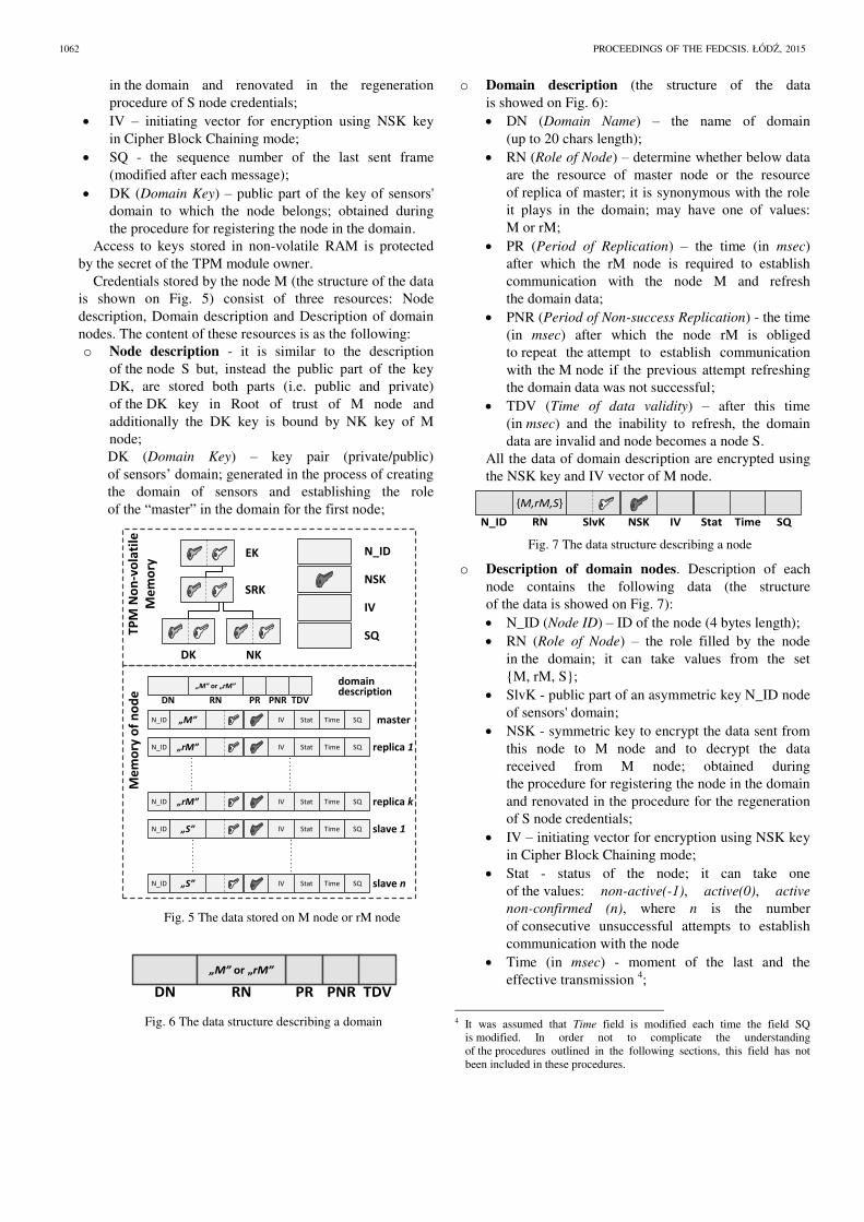
o Domain description (the structure of the data
is showed on Fig. 6):
DN (Domain Name) – the name of domain
(up to 20 chars length);
RN (Role of Node) – determine whether below data
are the resource of master node or the resource
of replica of master; it is synonymous with the role
it plays in the domain; may have one of values:
M or rM;
PR (Period of Replication) – the time (in msec)
after which the rM node is required to establish
communication with the node M and refresh
the domain data;
PNR (Period of Non-success Replication) - the time
(in msec) after which the node rM is obliged
to repeat the attempt to establish communication
with the M node if the previous attempt refreshing
the domain data was not successful;
TDV (Time of data validity) – after this time
(in msec) and the inability to refresh, the domain
data are invalid and node becomes a node S.
All the data of domain description are encrypted using
the NSK key and IV vector of M node.
N_ID SlvK NSK
{M,rM,S}
RN Stat Time SQIV
Fig. 7 The data structure describing a node
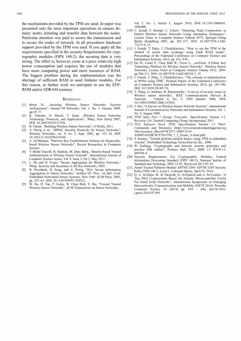
o Description of domain nodes. Description of each
node contains the following data (the structure
of the data is showed on Fig. 7):
N_ID (Node ID) – ID of the node (4 bytes length);
RN (Role of Node) – the role filled by the node
in the domain; it can take values from the set
{M, rM, S};
SlvK - public part of an asymmetric key N_ID node
of sensors' domain;
NSK - symmetric key to encrypt the data sent from
this node to M node and to decrypt the data
received from M node; obtained during
the procedure for registering the node in the domain
and renovated in the procedure for the regeneration
of S node credentials;
IV – initiating vector for encryption using NSK key
in Cipher Block Chaining mode;
Stat - status of the node; it can take one
of the values: non-active(-1), active(0), active
non-confirmed (n), where n is the number
of consecutive unsuccessful attempts to establish
communication with the node
Time (in msec) - moment of the last and the
effective transmission 4;
4 It was assumed that Time field is modified each time the field SQ
is modified. In order not to complicate the understanding
of the procedures outlined in the following sections, this field has not
been included in these procedures.
1062 PROCEEDINGS OF THE FEDCSIS. ŁODZ, 2015

SQ - the sequence number of the last sent frame
(modified after each message).
All node description data except N_ID field are
encrypted using the NSK key and IV vector of M node.
Key EK, SRK, NK and DK form a root of trust node M.
Access to keys from a root of trust and access to other data
in the non-volatile memory is protected by the secret
of the TPM module owner.
Because the description of the domain and descriptions
of nodes are encrypted, they can be stored outside the TPM
module non-volatile memory, for example in SD memory.
III. OPERATIONS IN THE WIRELESS SENSOR NETWORK WITH
AUTHENTICATION
In [19] was presented the concept of authentication
in WSNs using TPM. Ensuring proper authentication
of sensors in domain and correct data transfer between
sensors were taken into account in the concept. The concept
consist the following procedures:
1. Procedure for initiating M node.
2. Procedure for registering the S node in the domain
of sensors.
3. Procedure for removing rM or S node from
the sensors' domain.
4. Authentication procedure of the node.
5. Integration test of nodes in sensors' domain.
6. Procedure for the regeneration of S node credentials.
7. Procedure of sending data from S node to M node.
8. Procedure of reading data on M node which were
received from S node.
9. Procedure for giving role rM in the domain
for S node.
10. Procedure for updating resources of rM node based
on resources of M node.
11. Procedure for changing the node role from rM role
to role M;
12. Procedure for determining the "new" node M after
the failure of the "old" node M.
13. Integration test of resources of M and rM nodes.
In this study in the following sections the procedures
listed in paragraphs 1, 2, 7 and 8 are comprehensively
described. The procedures implementation details
are described in the next section.
A. The procedure for initiating M node
This procedure is intended to create the domain of sensors
and to initiate the node that will play the master
of the domain role.
Input data:
M node owner secret;
NK usage secret;
DN - sensors' domain name;
N_ID - node identifier;
time periods (i.e. PR, PNR and TDV) associated with
the operation of nodes rM..
The procedure for initiating M node comprises
the following steps:
1. Take ownership of the TPM and SRK key generation.
2. Generate asymmetric key NK (NK attributes: Binding,
Non-Migratable, Authority_always), SRK is a parent
of NK);
3. Put NK into the root of trust stored in the TPM
of “M” node.
4. Generate the data for M node:
generate asymmetric key DK for sensors' domain
and put it into the root of trust stored in the TPM
of “M” node (DK attributes: Storage, Migratable,
Authority_always), SRK is a parent of DK; later
public part of DK will be used by “S” node to bind the data which will be sent from “S” node
to “M” node);
generate symmetric key (NSK – size 32 bytes)
and initialization vector (IV – size 16 bytes)
for AES cryptography;
generate sequential number SQ for M node;
put M node data into non-volatile memory
of the TPM of S node.
5. Prepare of the domain description, which includes
the fields DN, RN, PR, PNR, TDV and then encrypt
this description using the NSK key and IV vector.
The RN field should have a content of "M".
6. Prepare of the M node description and then encrypt this
description using the NSK key, and IV. The fields
of the description should have the following values:
N_ID = input data N_ID (the field
is not encrypted);
RN = „M”;
SlvK = public part of the node NK key;
NSK = the node NSK key;
IV = initiating vector for NSK key;
Stat = 0;
Time = current time;
SQ = random number from the range <0; 65535>.
7. Save the M node description in M node resources.
B. The procedure for registering the S node in the domain
of sensors
In the procedure of registration S node in the domain
is assumed that during this procedure S node is connected
to the node M via the Serial interface5.
Input data:
N_ID - node identifier;
public part of the DK key.
After installing S node in serial port of M node
the procedure for registering S node in the domain comprises
the following steps:
1. On S node take ownership of the TPM and SRK key
generation.
5 If it was not possible to use the USB interface, in order to ensure the
safety of the registration procedure, is required to develop additional
ways of mutual authentication of both parties involved in the registration.
JANUSZ FURTAK, JAN CHUDZIKIEWICZ: SECURING TRANSMISSIONS BETWEEN NODES 1063

2. Generate asymmetric key NK of S node (NK attributes:
Binding, Non-Migratable, Authority_always); SRK is
a parent of NK).
3. Put NK to TPM resources of S node.
4. Generate the data for S node:
obtain the public part of the DK key from non-
volatile memory of the TPM of M node; send
a dom_pub_key_req packet from S node to M
node through the serial line: dom_pub_key_req
code
where:
code = 101 for dom_pub_key_req packet;
and get from M node a dom_pub_key_ans packet: dom_pub_key_ans
code DK
where:
code = 102 for dom_pub_key_ans packet;
DK public part of Domain Key of sensors’ domain;
generate symmetric key (NSK – size 32 bytes),
initialization vector (IV – size 16 bytes) for AES
cryptography;
put S node data into TPM non-volatile memory
of S node.
5. Prepare S node_description_req packet node_description_req
code N_ID NSK IV NK
where:
code = 103 for node_description_req packet;
N_ID, NSK, IV and public part of NK key
(the first three fields are bound using public part
of DK key).
6. Transfer the blob to M node and then unbind it using
the private part of DK key.
7. On M node prepare the S node description and then
encrypt this description using NSK key and IV vector
of M node. The fields of the S node description should
have the following values:
N_ID = input data N_ID (the field is not encrypted)
RN = „S”;
SlvK = public part of the S node NK key which
be registered;
NSK = the NSK key of node which be registered;
IV = initiating vector for NSK key;
Stat = 0;
Time = current time;
SQ = random number from the range <0; 65535>.
Save the S node description in M node resources.
8. Send a confirmation of registration to the node S.
The confirmation should contain N_ID, Time and SQ
and be encrypted using NSK key and IV vector
of node S.
node_description_ans
code N_ID Time SQ
where:
code = 104 for node_description_ans packet;
N_ID, Time and SQ (the fields are encrypted using
NSK key of S node).
9. Put SQ into TPM non-volatile memory of S node.
10. Uninstall the S node from serial port of M node
C. The procedure of sending data from S node to M node
Input data:
N_ID – identifier of node;
SD – sensor’s data;
NSK – symmetric key of S node;
IV = initiating vector for NSK key;
DK – public part of domain key.
N_ID SD SQ Hashcode
sensor packet
The structure of the frame containing the sensor data
is showed above. It includes the following fields:
code = 7 for sensor packet;
N_ID = input data N_ID;
SD = Sensor's Data encrypted using the NSK key and
IV vector;
SQ = current SQ incremented by 1;
Hash = the value of the hash function determined
on the basis of fields N_ID, SD and SQ.
The procedure of sending data from S node to M node
comprises the following steps:
1. Preparing sensor packet containing the sensor data,
as shown above
2. Binding the frame using the public part of DK.
3. Sending the frame to M node by XBee link.
4. Incrementing SQ field in resources of S node.
D. The procedure of reading data on M node which were
received from S node.
Input data:
Received frame from S node;
Resources of M node.
The procedure of receiving data on M node from S node
comprises the following steps:
1. Receiving of the frame, as shown on Fig. 8.
2. Unbinding of the frame using the private part of DK.
3. Searching the description of N_ID node in description
of domain nodes stored in protected resources of M
node. If not a success, the N_ID node is unrecognized.
4. Comparing SQ field from received frame and SQ field
from node description. If not equal, the SQ is incorrect.
5. Updating the description of N_ID node:
stat = 0;
Time = current time;
SQ = SQ+1.
1064 PROCEEDINGS OF THE FEDCSIS. ŁODZ, 2015

6. Decrypting of the SD field using the NSK and IV
acquired from description of domain nodes of “slave 1” node.
N_ID „S” stat time SQ
descriptio of „slave 1" from
resources of „ aster” ode
master slave 1sensor packet (wrapped)
RSA
eq
Y
”node unrecognized”
eq
N
”incorrect SQ”N
Y
AES
sensor data
update description of „slave 1" node:
N_ID SD SQ Hash„7"
N_ID SD SQ Hash„7"
„Master” node
Root of
trust
EK
SRK
NK
DK
IV
Fig. 8 The procedure of reading data on “master” node which
were received from “slave 1” node
IV. THE TESTBED TO EXAMINE AUTHENTICATION
PROCEDURES IN WSN
The laboratory stand to examine the authentication
procedures in WSN utilizing TPM was developed.
The laboratory stand includes a few sensors equipped with
TPM and several workstations to perform research. Block
diagram of the sensor is showed on Fig. 9 and view
of an exemplary sensor used in the experiments is showed
on Fig. 10.
XBee
Arduino
TPM
Sensor
Communication interface in WSN domain
Serial 0I2C
Analog /
DigitalSerial 2
Interface for node registering in WSN domain
Fig. 9 Block diagram of the sensor
Fig. 10 View of an exemplary sensor
Sensor (showed in Fig. 10) used in the experiments was
built with the following components:
Arduino Mega2560R3 (in Fig. 10, indicated by 1) –
based on microcontroller ATmega2560 (clock speed
16 MHz, 256 KB of flash memory for storing code
(of which 8 KB is used for the bootloader), 8 KB
of SRAM and 4 KB of EEPROM). The board has:
54 digital input/output pins (of which 15 can be used
as PWM outputs), 16 analog inputs, 4 UARTs
(hardware serial ports).
XBee 1mW Wire Antenna Series 1 (indicated by 2) –
wireless communication module with other wireless
modules (compatible with the 802.15.4 standard).
The module is connected to the Arduino Mega
by adapter XBee Shield (indicated by 3) and
communicates with Arduino by Serial 0.
Ultrasonic distance sensor (indicated by 6) includes
ultrasonic transmitters, receiver and control circuit.
Provides 2cm - 400cm non-contact measurement
function, the ranging accuracy can reach to 3mm.
TPM (indicated by 5) – detachable part of hardware
component of Atmel I2C/SPI Demonstration Kit
connected to Arduino through the I2C Interface.
Power bank (indicated by 4) – 9V power supply.
Fig. 11 Atmel I2C/SPI Demonstration Kit
In this laboratory stand was realized an experiment
consisting of the following stages:
1. Initiating M node.
2. Registering the S node in the domain of sensors.
3. Transferring data from S node to M node:
Part used in experiment
- TPM module
5 4
6
2 1
3
JANUSZ FURTAK, JAN CHUDZIKIEWICZ: SECURING TRANSMISSIONS BETWEEN NODES 1065

a) sending a first frame (its structure is shown
in subsection III.C) from node S to M as a plain
text i.e. without encryption field SD and without
binding frame with the public part of DK.
b) sending a second frame (its structure is the same)
from S to M node containing encrypted SD field
with NSK, but without binding the frame with
the public part of DK;
c) sending a third bound frame with the public part
of DK from S to M node containing encrypted
SD field with NSK.
STAGE 1. The entire first stage is initiated and
implemented autonomously on the node that will act as the
Master. After this step this step the TPM is initiated and
node ownership is acquired. The description of M node
is written in non-volatile memory of TPM. Moreover,
encrypted6 description of sensors domain, in which
is registered one node (i.e. Master), is created. Exemplary,
encrypted description of sensors domain which was created
as a result of this step for M node (node ID is 0xCC CC CC
CC) is shown in Fig. 12.
Fig. 12 Description of sensors domain after M node
initiating procedure
6 In description of sensors domain all fields are encrypted with the
exception of node IDs
STAGE 2.
Before the start of the second stage S node should be
connected to the node M over a Serial. The data shown have
been partially modified during the implementation of the
method to those described in [13], as shown in Fig. 13.
XBee
Arduino
TPM
S node
Serial 0I2C
Serial 2
Sensor
Analog /
Digital
XBee
Arduino
TPM
Sensor
M node
Serial 0I2C
Analog /
DigitalSerial 2
Interface for node registering in WSN domain
Fig. 13 Block diagram of M node and S node during the
procedure of S node registering
Fig. 14 Description of sensors domain after S node
registering procedure
In the first three steps of the stage TPM of S node
is initiated, node ownership is acquired and the root of trust
on S node is created. Then direct connection to M by Serial
interface node is needed to transfer public part of the DK.
DK is transferred as a plain text. In next step NSK and IV
is randomly generated and put into non-volatile memory
of S node. Then N_ID, NSK, IV and public part of NK key
are bound using public part of DK key and transferred to M
node through the Serial interface. On the basis of these data
M node prepares a description of the node S and attach it
--- Domain description
60 1C 38 44 45 82 63 85 51 5D 54 B4 1F 53 32 AC
0D 0E 20 DC 64 ED C5 C5 07 75 56 C9 27 62 D6 90
FD 69 21 98 B8 3B 2A CD 4D 48 AC FB 14 55 DD 5C
--- Descriptions of nodes - type: MASTER
--- Node ID CC CC CC CC
--- Node description:
41 84 F7 D4 1A 69 FF 4B 0C 42 ED 0E 13 3D F7 76
72 4C 7C 8A 23 B2 52 F4 7E 4F AF D5 8A C9 9A 90
14 E0 2F DD 0E B1 70 9D F5 F3 4C 7F 9D F3 15 0C
AA D9 77 0D 64 7F 6C 23 F4 D6 3F F5 34 B5 1E 9D
6B 67 BB A7 33 C9 D8 7C 6C 27 5D 96 A7 06 83 F9
23 15 49 B5 A1 86 08 6C 06 ED 46 8A 73 5B B6 1B
11 BC 18 D8 FA E1 EF 21 6A A1 64 93 B4 08 03 DE
FC 9E 85 88 DF 71 56 52 B8 27 65 D3 89 44 DD 9E
D8 D5 96 3B 91 BE 52 B7 DB EE 40 F8 F4 19 55 A8
0E 6A 99 81 9A AB 2A 41 E0 07 A7 89 2C E6 01 C8
CA C2 3B 25 63 48 9A 97 6E 6F 46 88 E6 A9 54 F6
98 88 7F F3 4A A4 68 C0 E1 C3 05 F4 01 38 A7 5E
B5 4E 25 DF A5 8B 61 45 A1 1F 0B 3F B9 36 E2 67
07 17 2A EB F3 3A C3 2E D5 F5 38 B6 A5 E2 D7 00
52 0C 47 6A 5B 69 D6 E2 14 FC 55 DB 53 1A 1E 1D
9E 0C 18 2E 4D FE 69 BD 08 B2 7F E6 20 96 A9 0E
EC 66 C5 67 30 8F AD E3 71 B9 93 91 67 53 B8 83
91 09 2B 12 4E DD F6 4F FD 93 6C C8 A6 9B 2C 9F
D2 42 FA 4A C0 95 98 BB C8 F6 55 4D A2 B9 E2 61
58 58 FB F9 89 C8 51 DF 76 59 EF 6C F9 27 49 39
ED C6 92 B8 76 81 BF 6F F6 DA 16 0C 22 AB A0 D7
54 00 CD F6 5E A8 83 75 09 F3 AB 76 DC 37 C2 C6
--- Descriptions of nodes - type: REPL. of MASTER
No nodes
--- Descriptions of nodes - type: SLAVE
No nodes
--- Domain description
60 1C 38 44 45 82 63 85 51 5D 54 B4 1F 53 32 AC
0D 0E 20 DC 64 ED C5 C5 07 75 56 C9 27 62 D6 90
FD 69 21 98 B8 3B 2A CD 4D 48 AC FB 14 55 DD 5C
--- Descriptions of nodes - type: MASTER
--- Node ID CC CC CC CC
--- Node description:
41 84 F7 D4 1A 69 FF 4B 0C 42 ED 0E 13 3D F7 76
72 4C 7C 8A 23 B2 52 F4 7E 4F AF D5 8A C9 9A 90
| | |
| | |
| | |
ED C6 92 B8 76 81 BF 6F F6 DA 16 0C 22 AB A0 D7
54 00 CD F6 5E A8 83 75 09 F3 AB 76 DC 37 C2 C6
--- Descriptions of nodes - type: REPL. of MASTER
No nodes
--- Descriptions of nodes - type: SLAVE
--- Node ID 01 01 01 01
--- Node description:
14 CE E3 D8 D1 E7 C0 6B 5B 19 D0 D6 20 87 57 88
CD DC EB 97 17 08 E8 BF 0F 00 4B D1 E7 6E 27 0D
| | |
| | |
| | |
13 36 1F E6 9A 56 0B B6 3F EF A1 D9 89 98 13 9B
E2 5C 7E 9E 46 0B 37 C0 C2 2D AB 9C 25 C3 69 D9
1066 PROCEEDINGS OF THE FEDCSIS. ŁODZ, 2015

to the sensors' domain description. Now domain description.
After it the domain description might look like on the Fig. 14.
In the last step confirmation of S node registering
(encrypted using NSK key of S node) is sent to S node.
In this moment S node is registered and should
be disconnected from Serial interface connecting it with
M node.
STAGE 3.
The S node is ready to transfer its sensor data by XBee
interface – Serial line used in stage 2 is disconnected.
In experiment takes part, in addition to S and M node,
Observer station equipped with Xbee interface as shown
on Fig. 15 and Fig. 16.This node is designed to interception
the data transmission between nodes S and M.
Observer
Arduino
TPM
S node
Serial 0I2C
Serial 2
X
XBee
Sensor
Analog /
Digital
XBee
Arduino
TPM
M node
Serial 0I2C
Serial 2
Interface for node registering in WSN domain
Sensor
Analog /
Digital
Fig. 15 Block diagram of M node, S node and observer during
transferring data between S node and M node
Fig. 16 View of the testbed during transferring data between S node
and M node
Data received in step a) by nodes M and Observer should
be the same - an example is shown in Fig. 17.
Fig. 17 Data received on M node and on Observer node in
step a)
Data received in step b) by nodes M and Observer are also
the same, but for M node NSK key of S node is known
and it can decrypt the SD field from received frame. The
result is showed on Fig. 18.
Fig. 18 Data after step b)
Data received in step c) by nodes M and Observer are also
the same, but M node knows NSK key of S node and private
part of DK and M node can first unbind received frame and
then decrypt the SD field from the frame. The result
is showed on Fig. 19.
Fig. 19 Data after step c).
The experiment shows that the data transferred between
nodes S and M are secured. Unauthorized nodes that are not
registered in the domain of sensors, even if they are able
to receive the data, they are not able to use them.
V. CONCLUSION
This paper presents the model, concept of authentication
in sensors' domain and implementation of securing
transmissions between nodes of WSN. For this purpose,
TPM
M node
S node
observer TPM
distans
sensor
Observer node
60 1C 38 44 45 82 63 85 51 5D 54 B4 1F 53 32 AC
0D 0E 20 DC 64 ED C5 C5 07 75 56 C9 27 62 D6 90
M node
--- Sensor packet
00 07 01 01 01 01 01 77 03 03 63 B4 1F 53 32 AC
0D 0E 20 DC 64 ED C5 C5 07 75 56 C9 27 62 00 00
received data are
decrypted using NSK key
Observer node
E8 BF 0F 00 4B D1 E7 6E 27 AB 76 DC 37 C2 DC 64
ED C5 C5 07 D2 42 FA 4A C0 95 98 BB C8 F6 A2 B9
23 15 49 B5 A1 86 08 6C 06 ED 46 8A 73 5B B6 1B
| | |
| | |
11 BC 18 D8 FA E1 EF 21 6A A1 64 93 B4 08 03 DE
FC 9E 85 88 DF 71 56 52 B8 27 65 D3 89 44 DD 9E
D8 D5 96 3B 91 BE 52 B7 DB EE 40 F8 F4 19 55 A8
M node
--- Sensor packet
00 07 01 01 01 01 01 77 03 03 63 B4 1F 53 32 AC
0D 0E 20 DC 64 ED C5 C5 07 75 56 C9 27 62 00 00
received data are unbound and decrypted
using NSK key
Observer node
00 07 01 01 01 01 01 77 03 03 63 B4 1F 53 32 AC
0D 0E 20 DC 64 ED C5 C5 07 75 56 C9 27 62 00 00
M node
--- Sensor packet
00 07 01 01 01 01 01 77 03 03 63 B4 1F 53 32 AC
0D 0E 20 DC 64 ED C5 C5 07 75 56 C9 27 62 00 00
code SD SQ N_ID pad Hash
JANUSZ FURTAK, JAN CHUDZIKIEWICZ: SECURING TRANSMISSIONS BETWEEN NODES 1067
the mechanisms provided by the TPM are used. In paper was
presented only the most important operations in sensors do-
main: nodes initiating and transfer data between the nodes.
Particular attention was paid to secure the transmission and
to secure the nodes of network. In all procedures hardware
support provided by the TPM was used. If you apply all the
requirements specified in the security Requirements for cryp-
tographic modules (FIPS 140-2), the securing data is very
strong. The effect is, however, come at a price relatively high
power consumption and requires the use of modules that
have more computing power and more resources of RAM.
The biggest problem during the implementation was the
shortage of sufficient RAM in used Arduino modules. For
this reason, in further work we anticipate to use the EEP-
ROM and/or SDRAM memory.
REFERENCES
[1] Boyle D., „Securing Wireless Sensor Networks: SecurityArchitectures”, Journal Of Networks, Vol. 3, No. 1, January 2008,pp.65-77.
[2] K. Sohraby, D. Minoli, T. Znati, „Wireless Sensor NetworksTechnology, Protocols, and Applications”, Wiley, New Jersey 2007,DOI: 10.1002/047011276X.
[3] R. Faludi, “Building Wireless Sensor Networks”, O’Reilly, 2011.[4] A. Perrig et al., “SPINS: Security Protocols for Sensor Networks”,
Wireless Networks, vol. 8, no. 5, Sept. 2002, pp. 521–34, DOI:10.1023/A:1016598314198.
[5] A. Al-Dhelaan, “Pairwise Key Establishment Scheme for Hypercube-based Wireless Sensor Networks”, Recent Researches in ComputerScience.
[6] Y Mohd Yussoff, H. Hashim, M. Dani Baba, “Identity-based TrustedAuthentication in Wireless Sensor Network”, International Journal ofComputer Science Issues, Vol. 9, Issue 3, No 2, May 2012.
[7] L. Hu and D. Evans, “Secure Aggregation for Wireless Networks,”Wksp. Security and Assurance in Ad Hoc Networks, 2003.
[8] B. Przydatek, D. Song, and A. Perrig, “SIA: Secure InformationAggregation in Sensor Networks,” SenSys '03: Proc. 1st Int'l. Conf.Embedded Networked Sensor Systems, New York: ACM Press, 2003,pp. 255–65, DOI: 10.1145/958491.958521.
[9] W. Hu, H. Tan, P. Corke, W. Chan Shih, S. Jha, “Toward TrustedWireless Sensor Networks”, ACM Transactions on Sensor Networks,
Vol. 7, No. 1, Article 5, August 2010, DOI: 10.1145/1806895.1806900.
[10] C. Krauß, F. Stumpf, C. Eckert, “Detecting Node Compromise inHybrid Wireless Sensor Networks Using Attestation Techniques”,Lecture Notes in Computer Science Volume 4572, Springer-VerlagBerlin Heidelberg 2007, pp. 203–217, DOI: 10.1007/978-3-540-73275-4_15.
[11] J. Furtak, T. Pałys, J. Chudzikiewicz, “How to use the TPM in themethod of secure data exchange using Flash RAM media”,Proceedings of the Federated Conference on Computer Science andInformation Systems, 2013, pp. 831–838.
[12] Hu W., Corke P., Chan Shih W., Overs L., „secFleck: A Public KeyTechnology Platform for Wireless Sensor Networks”, Wireless SensorNetworks, Lecture Notes in Computer Science Volume 5432, 2009,pp 296-311, DOI: 10.1007/978-3-642-00224-3_19.
[13] J. Furtak, T. Pałys, J. Chudzikiewicz, “The concept of authenticationin WSNs using TPM”, Position Papers of the Federated Conferenceon Computer Science and Information Systems, 2014, pp. 183-190,DOI: 10.15439/2014F176.
[14] Y. Wang, G. Attebury, B. Ramamurthy, “A survey of security issues inWireless sensor networks”, IEEE Communications Surveys &Tutorials, , Volume 8, No. 2, 2ND Quarter 2006, DOI:10.1109/COMST.2006.315852.
[15] J. Sen, “A Survey on Wireless Sensor Network Security”, InternationalJournal of Communication Networks and Information Security, Vol. 1,No. 2, August 2009.
[16] TPM Main Part 1 Design Principles. Specification Version 1.2.Revision 116, Trusted Computing Group, Incorporated, 2011
[17] TCG Software Stack (TSS) Specification Version 1.2 Part1:Commands and Structures (http://www.trustedcomputinggroup.org/files/resource_files/6479CD77-1D09-3519-AD89EAD1BC8C97F0/TSS_1_2_Errata_A-final.pdf).
[18] S. Kinney, “Trusted platform module basics: using TPM in embeddedsystems”, Embedded Technology Series,Elsevier Inc., 2006
[19] W. Stallings “Cryptography and network security principles andpractice fifth edition”, Prentice Hall, 2011, ISBN 13: 978-0-13-609704-4.
[20] Security Requirements For Cryptographic Modules. FederalInformation Processing Standard (FIPS 140-2), National Institut ofStandard and Techology, 2002-12-03. Retrieved 2013-05-18.
[21] Atmel Trusted Paltform Module AT97SC3204/ AT97SC3205 SecurityPolicy FIPS 140-2, Level 1, Colorado Sprins, April 03, 2014.
[22] Q. A. Al-Haija, M. Al Tarayrah, H. Al-Qadeeb and A. Al-Lwaimi, “ATiny RSA Cryptosystem Based On Arduino Microcontroller UsefulFor Small Scale Networks”, International Symposium on EmergingInter-networks, Communication and Mobility (EICM 2014), ProcediaComputer Science 34 (2014) pp. 639 – 646, doi:10.1016/j.procs.2014.07.091.
1068 PROCEEDINGS OF THE FEDCSIS. ŁODZ, 2015