Embed Size (px)
Citation preview
Secure Pairwise Key Establishment in Large-scale
Sensor Networks: An Area Partitioning and
Multi-group Key Predistribution Approach
Dijiang Huang
Arizona State University
Deep Medhi
University of Missouri–Kansas City
Existing pairwise key establishment schemes for large-scale sensor networks are vulnerable tovarious passive or active attacks. We classify attacks as: selective node capture attacks, nodefabrication attacks, and insider attacks. In order to improve the security robustness of randomkey predistribution and pairwise key establishment schemes against these attacks, we proposea 5-phase pairwise key predistribution and pairwise key establishment approach by using areapartitioning and multi-group key predistribution. Our security performance studies show that ourproposed approach is resilient to selective node capture and node fabrication attacks, and restrictsthe consequence of any insider attack to a minimal level.
Categories and Subject Descriptors: C.2.0 [COMPUTER-COMMUNICATION NETWORKS
]: General—Security and protection; C.2.4 [COMPUTER-COMMUNICATION NETWORKS
]: Distributed Systems —Distributed applications
General Terms: Security
Additional Key Words and Phrases: Sensor, Selective Node Capture, Node Fabrication, Insiderattack
1. INTRODUCTION
Large-scale distributed sensor networks are composed of a large number of low-power sensor devices, for example, SmartDust[Kahn et al. 1999] and WINS [Pottieand Kaiser 2000]. Typically, these networks are installed to collect sensed datafrom sensors deployed in a large area, as shown in Figure 1. Sensor networks oftenhave one or more centralized controllers called base stations or sinks. A base sta-
c© ACM, 2007. This is the author’s version of the work. It is posted here by permission of ACMfor your personal use. Not for redistribution. The definitive version was published in PUBLICA-TION, VOL , NO , August 2007 http://portal.acm.org/browse dl.cfm?idx=J789
Authors address: Dijiang Huang, Computer Science and Engineering Department, Arizona StateUniversity, 699 S. Mill Ave. Suite 470, Tempe, AZ. 85287-8809. Deep Medhi, Computer Sci-ence and Electrical Engineering Department, University of Missouri, 550F Flarsheim Hall, 5100Rockhill Road, Kansas City, MO. 64110; email:[email protected], [email protected] to make digital/hard copy of all or part of this material without fee for personalor classroom use provided that the copies are not made or distributed for profit or commercialadvantage, the ACM copyright/server notice, the title of the publication, and its date appear, andnotice is given that copying is by permission of the ACM, Inc. To copy otherwise, to republish,to post on servers, or to redistribute to lists requires prior specific permission and/or a fee.c© 2007 ACM 0000-0000/2007/0000-0001 $5.00
ACM Journal Name, Vol. , No. , August 2007, Pages 1–0??.

2 · D. Huang and D. Medhi
High-bandwidth Link
Core Network
Sensor field
Base Station
Sensor
Data Center
Key Server
Router
Communication Range
Up/Down Stream Wireless Link
Fig. 1. Sensor network architecture.
tion, usually many orders of magnitude more powerful than a sensor, is typically agateway to other networks or data centers via high bandwidth communication links(either leased lines or broadband wireless links). They can be used as a nexus todisseminate control information into the network or extract data from it. Sensorsare constrained to lower-power and lower-bandwidth usage; thus, most deployedsensors may not be able to communicate with the base station directly requiringsensed data to be aggregated at some forwarding nodes. As a result, communi-cation types should be either one-to-many to disseminate control commands fromthe base station to each sensor, or many-to-one to collect sensed data from eachsensor to the base station. For example, as shown in Figure 1, double-head linesform up/down stream wireless links which connect all aggregation nodes. Aggre-gation nodes can be dynamically selected, for example, using an election protocol(e.g., LEACH [Ganesan et al. 2001], TEEN [Manjeshwar and Agrawal 2001], andPEGASIS [Lindsey and Raghavendra 2002]) where each aggregation node collectssensor readings from surrounding nodes and forwards a single message contain-ing aggregated information. In this way, a multi-hop wireless network is formedto allow sensors to communicate to the nearest base station. Thus, in large-scaledistributed sensor networks, a critical security service is to provide direct securecommunication channels or links among sensors.
As specified in [Akyildiz et al. 2002], the number of sensor nodes deployed forstudying a phenomenon may be on the order of hundreds of thousands. Dependingon the application, the number may reach an extreme value of millions. Due toinherent storage constraints, it is infeasible for a sensor device to store a uniqueshared key for every other sensor in the system. A naıve solution is to use a commonkey between every pair of sensors which can overcome storage constraints, butoffers weak security. In this case, if just a single node is compromised, the entiresystem is compromised. Recently, Random Key Predistribution (RKP) schemeswere proposed [Eschenauer and Gligor 2002; Chan et al. 2003; Liu and Ning 2003a;Liu et al. 2005; Du et al. 2003; Du et al. 2005] for large-scale distributed sensornetworks. These schemes randomly select a subset of keys from a large key pool
ACM Journal Name, Vol. , No. , August 2007.

Secure Pairwise Key Establishment in Large-scale Sensor Networks · 3
for each sensor. Since the RKP schemes preinstall a limited number of keys in eachsensor, after being deployed, a sensor is not guaranteed to share a key with each ofits neighbors. Thus, a sensor can establish pairwise keys via those neighbors withwhich it already shares preinstalled keying materials. For RKP, a Pairwise KeyEstablishment (PKE) protocol is needed to set up shared keys with neighbors.
1.1 Issues of Existing RKP Schemes
For current RKP schemes, analyses of the security strength are done on the basis ofthe number of communication links that can be compromised due to compromisedsensors in the network; furthermore, compromised nodes are randomly captured inexisting security analysis models. To mitigate the random node capture attack, Duet al. [Du et al. 2004], Liu and Ning [Liu and Ning 2003b; 2005] proposed usingdeployment information (sensor location information) to improve the resilience tothe node capture attack. However, in practice, the open or hostile deploymentenvironment of sensor networks makes it easier for attackers to locate and selectivelycapture sensors. Moreover, due to the lack of node authentication, attackers caneasily fabricate nodes by using the secrets which are preinstalled in the capturednodes.
It may be noted that PKE protocols are vulnerable to insider attacks, in whichthe attacker can fabricate captured sensors, implant malicious codes, and deploythe fabricated sensors back into the sensor networks. These fabricated sensors canmalfunction the PKE protocol by sniffing the encrypted key message, dropping,forging, and redirecting the key message, etc.
1.2 Overview of Proposed Approach
In this paper, we propose a comprehensive solution for the RKP-PKE scheme to pre-vent and mitigate various types of attacks. We present our scheme in five phases. Inour scheme, a sensor deployment area is first partitioned into multiple small squareareas (zones) and then, sensors deployed in each zone form a group. This designcan restrict the consequence of attacks (such as insider attacks) within a smallrange. We utilize the unconditionally secure and λ-collusion resistant properties ofthe group keying scheme proposed in [Blundo et al. 1998] to construct key spacesand restrict the number of deployed secrets of a key space to no more than λ. Inthis way, we can effectively prevent attackers from sniffing traffic and fabricatingnew sensors via captured keys. To improve resilience to insider attacks, we proposea source routing based multi-path PKE protocol. This multi-path PKE protocolutilizes (n, k) Reed-Solomon error correcting codes to set up pairwise keys and itis resilient to t = (n − k)/2 paths are faulty.
1.3 Main Contributions
Our main contributions are in two directions:
(1) We propose a λ-restricted area partitioning and multi-group key predistributionscheme to scale the network size due to the key storage constraints of sensors.Compared to previous work, our scheme can completely prevent selective nodecapture attacks. In addition, attackers cannot fabricate new sensors to setup pairwise keys with uncompromised sensors in our scheme. Our scheme also
ACM Journal Name, Vol. , No. , August 2007.

4 · D. Huang and D. Medhi
restricts the node replication attack within the partitioned zone where the nodeis captured. Thus, it is more difficult for attackers to duplicate captured sensorsand to distribute them in other zones in order to compromise the entire sensornetwork.
(2) We use the multiple node-disjoint-path pairwise key establishment protocoland fault-tolerance coding scheme (Reed-Solomon codes) to improve resilienceto insider attacks, such as stop forwarding and cheating. With our scheme, asensor would be able to recover the key establishment message due to packetdropping as well as to identify faulty paths that alter a forwarded key message.
1.4 Organization
The rest of the paper is organized as follows: In Section 2, we present the relatedwork. In section 3, we highlight the proposed five phases of our pairwise key setupscheme and attack model. The details of our scheme is presented in Section 4. FromSection 5 to Section 7, we discuss the performance of our scheme against selectivenode capture attacks, node fabrication attacks, and insider attacks. The operationalperformance assessments such as communication, storage, and computation, arepresented in Section 8. In Section 9, we present a summarization of our approachand the security challenges for RKP-PKE schemes.
2. RELATED WORK
We broadly classify the random key predistribution (RKP) schemes for sensor net-works into two groups: Purely Random Key Predistribution (P-RKP) schemes andStructured Key-pool Random Key Predistribution (SK-RKP) schemes. The P-RKP scheme was first proposed by Eschenauer and Gligor [Eschenauer and Gligor2002], and we refer to it as the basic scheme. Several schemes have been developedwhich were all based on the basic scheme; these schemes improve the basic schemein five aspects: 1) shared keys threshold: q-composite scheme [Chan et al. 2003]; 2)key pool structure: SK-RKP schemes [Liu and Ning 2003a; Liu et al. 2005; Du et al.2003; Du et al. 2005]; 3) path-key establishment protocol: k-path key establishmentschemes [Chan et al. 2003; Zhu et al. 2003]; 4) location awareness schemes [Liu andNing 2003b; 2005; Du et al. 2004]: key predistribution and sensors’ deployment arebased on known sensors deployment information; 5) shared keys discovery schemes[Di Pietro et al. 2004; Mehta et al. 2005]: one-way function schemes have beenproposed to reduce the communication overhead during the key discovery phase inorder to improve resilience to a node fabrication attack.
Note that the above discussed schemes assume that the attacker randomly cap-tures sensors in order to compromise the sensor network. However, we argue thatin reality, attackers are often very smart and they might be able to figure out at-tacking strategies to maximize gains with minimal attacking efforts. To analyzemore sophisticated attacks, a preliminary analysis of selective node capture attackand node fabrication attack was presented in [Huang et al. 2004].
Before we discuss additional related work, we state a few terms from existingliterature: if two neighbors share a preinstalled key, the key is called a direct key.If two neighbors do not share a preinstalled key, they need to find a path that isprotected by direct keys to establish a pairwise key. The established pairwise key
ACM Journal Name, Vol. , No. , August 2007.

Secure Pairwise Key Establishment in Large-scale Sensor Networks · 5
is called an indirect key. To safeguard the indirect key, multiple key-path schemeshave been proposed in [Chan et al. 2003] and [Zhu et al. 2003] to prevent faultysensors from deriving indirect keys. In [Chan et al. 2003], multiple physically link-disjoint paths between two nodes are used to set up an indirect key. When twonodes u and v want to set up an indirect key via multiple (say j > 1) link-disjointpaths, the source node, u, selects j secrets, s1, . . . , sj , and sends each of these secretsonto a unique key establishment path. To secure a secret message, s1, via a keyestablishment path, u → x → v, following key establishment steps are performed:
u → x : {s1}kux; x → v : {s1}kxv
,
where kux and kxv are direct keys shared between pair (u, x) and pair (x, v), respec-tively. Upon receiving all the secrets, node v simply uses bitwise XOR operationto derive the indirect key, i.e.,
indirect key = s1 ⊕ . . . ⊕ sj. (1)
In [Zhu et al. 2003], multiple logical link-disjoint paths between two nodes areused for setting up an indirect key. A logical path means that there exists a keysharing relation among source, destination, and intermediate nodes along the keyestablishment path. For example, source node u shares t1 direct keys with interme-diate node x, and node x shares t2 direct keys with destination node v; note that uand v do not share a direct key. Since a direct key can be only used for one logicalpath, there can be zx = min(t1, t2) key establishment paths between u and v viaintermediate node x. The secrets selection and transmission proposed in [Zhu et al.2003] is similar to that described in [Chan et al. 2003]. The difference is the useof physical or logical key establishment paths in corresponding proposed schemes.
Both proposed multi-path key establishment schemes are efficient to guard againstoutsider’s node capture attacks and insider attacks that passively learn the for-warded messages. However, they are vulnerable to active insider attacks, i.e., anattacker can stop forwarding secrets or alter the forwarded secrets which can pre-vent the receiver from deriving the right indirect key. In order to counter activeinsider attacks, we have earlier proposed a Reed-Solomon code and multi-path keyestablishment protocol to enable a sensor to identify the faulty key establishmentpaths in a preliminary study [Huang and Medhi 2005].
The local key-graph connectivity is important for evaluating the communica-tion overhead and storage overhead of a RKP-PKE approach. Random graphtheory [Spencer 2001] based approaches have been adopted by existing RKP-PKEsolutions such as [Eschenauer and Gligor 2002]. In a recent work [?], it has beenshown that the random graph based solutions introduce errors when the group sizeis either big or small. Moreover, the random graph based solution is unable toprovide the key-path length information. These problems are solved by by usinga modified binomial distribution in a hop-by-hop fashion to evaluate the local keygraph connectivity for a key path within h hops. However, multipath key graphconnectivity (within 2 hops) and predistribution approaches were not addressed in[?]—the scope of this paper is to address these aspects along with a comprehensiveanalysis of node fabrication and node capture attacks.
ACM Journal Name, Vol. , No. , August 2007.

6 · D. Huang and D. Medhi
Key predistributionSensor
deploymentKey discovery
Pairwise key establishment
Random key predistribution
Phase 2 Phase 3 Phase 4 Phase 5
Pre-deployment
Sensor groups partitioning
Phase 1
Deployment areas partitioning
Polynomial key spaces creation
Uniform distribution
Deployment techniques
Polynomial key agreement protocol
Key-ring id broadcasting
K-disjoint paths pairwise key setup
Key-graph creation
Goals of Phase 1 and Phase 2:1. Reduce the deployment complexity: maximize the size of sub-area2. Reduce the memory overhead of sensors: minimize the number of installed keys3. Guard against security attacks: 1. Against node capture attack 2. Against node fabrication attack
Goals of Phase 3 and Phase 4:1. Reduce the complexity of sensing applications: Uniform distribution2. Reduce the communication overhead: Key-ring id broadcasting
Goal of Phase 5 :Increase the robustness to insider attack
Fig. 2. A taxonomy of RKP-PKE schemes.
3. SYSTEM MODELS OF OUR SCHEMES
3.1 A Generalized RKP-PKE Model
Our approach involves five phases as shown in Figure 2. Here, we highlight thefunctionalities for each phase of these five phases:
1. Pre-deployment phase: A sensor deployment area is first partitioned into multi-ple sub-areas. A group of sensors is predetermined for deployment in a sub-area.
2. Key predistribution phase: A centralized key server generates a structure keypool for each sensor group. A structure key pool is composed of multiple keyspaces (key matrices). The key predistribution is described later in Section 4.2.After key predistribution, each sensor is assigned a unique key ring id. The keyring id can identify the sensor’s position in each key space, and thus, it helpsto establish pairwise keys with other sensors in the key discovery phase and thepairwise key establishment phase.
3. Sensor deployment phase: Sensors are deployed in a two-dimensional plane.Based on group partitions, each group of sensors are uniformly1 deployed ineach sub-area.
4. Key discovery phase: Once sensors are deployed, three steps are involved in thekey discovery phase.
step 1:. Each sensor broadcasts its key-ring id to all its neighbors.
step 2:. Based on the received key-ring id, a sensor can determine its neighbor-reachability list, and then it broadcasts its neighbor-reachability list.
1For discussion on why we emphasize on using uniform distribution, see Section 4.3.
ACM Journal Name, Vol. , No. , August 2007.
Secure Pairwise Key Establishment in Large-scale Sensor Networks · 7
1
9
8
7
6
5 4 3
2
k 13
k 19
k 12
k 34
k 49
k 29
k 27
k 78
k 58
k 35
k 46 k 56
k 79
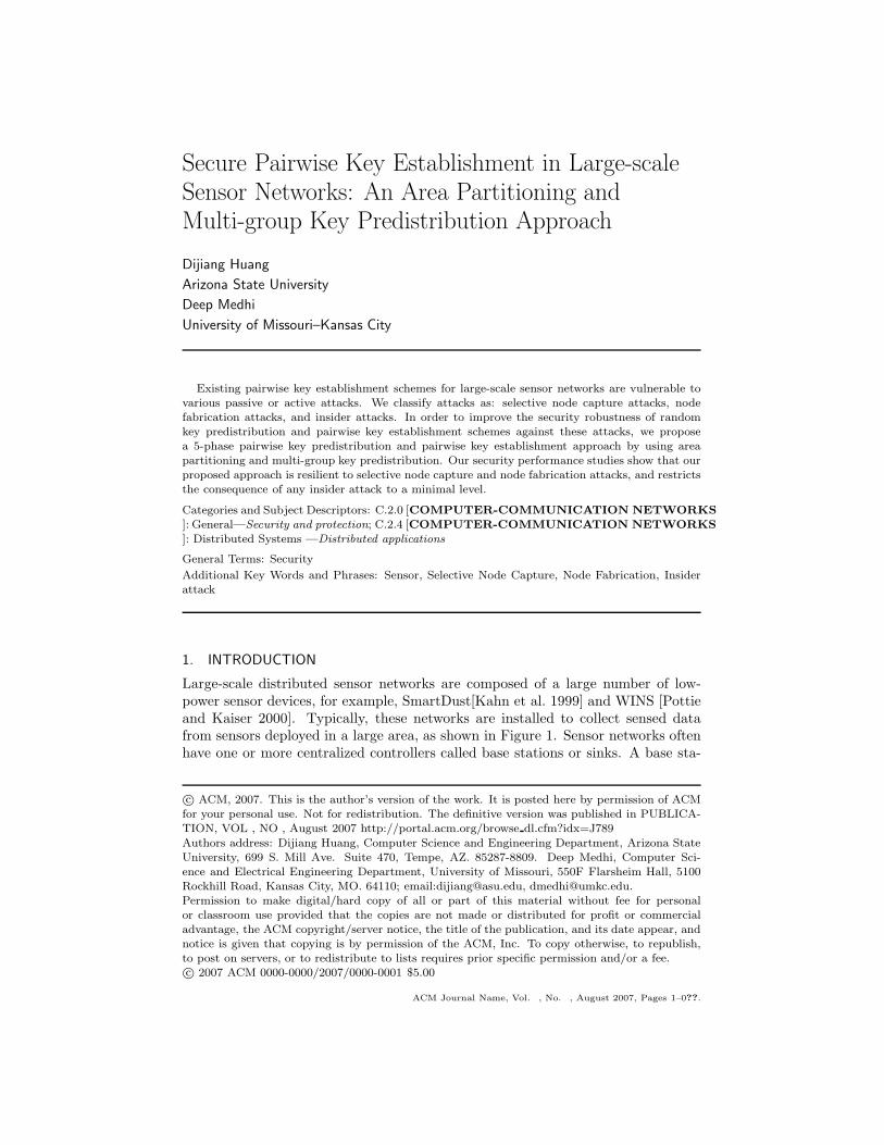
Fig. 3. A local key graph for sensor 1. kxy represents a direct key between x and y and thedot circle represents the communication range of sensor 1. In this key graph, node 1 can set upindirect keys with all its communication neighbors within 3 hops.
step 3:. Based on the received neighbor-reachability list, a sensor can builda local key graph (shown in Figure 3) which represents the node-connectivityfrom the view of each individual node. We note that in the local key graph, iftwo sensors share a direct key, we refer to it as a link connecting two sensorsdirectly.
5. Pairwise key establishment phase: In a local key graph, if there is no link be-tween two sensors, i.e., they do not share a direct key, the PKE protocol willbe used to set up an indirect key via multiple hops (i.e., a key path) in the localkey graph. The established pairwise key is called an indirect key. The indirectkey establishment includes two phases:
(a) The key establishment within a zone.(b) The key establishment among adjacent zones.
In order to counter insider attacks, such as the insider broadcast incorrectneighbor-reachability list and drop and/or alter the key establishment packets,a multi-path key establishment protocol is proposed to counter insider attacks.
3.2 Attack Model
As classified in [Karlof and Wagner 2003], a laptop-class attacker can have morepowerful devices, like laptops or their equivalents. Thus, they have an advantageover legitimate nodes: they may have greater battery power, a more capable CPU,a high-power radio transmitter, or a sensitive antenna. We assume that the goalof attackers is to compromise the pairwise keys established or to be establishedbetween any two sensors. Furthermore, the following capabilities of an attacker areassumed:
—The attacker has unlimited energy and computing power.
—The attacker knows all the information stored in a sensor once the sensor iscaptured.
—The attacker can listen to and record all the traffic in the network.
ACM Journal Name, Vol. , No. , August 2007.

8 · D. Huang and D. Medhi
—The attacker has the ability to physically locate a given sensor by listening tothe traffic.
—The attacker has the ability to fabricate similar nodes, deploy, and control them.
We classify attacks to RKP-PKE schemes into three categories.
—Selective node capture attack: attacking communication link2. Most of previoussecurity analysis for RKP-PKE schemes assumes that attackers randomly capturesensors to compromise preinstalled keys. However, the random node-capturingassumption is weak. For example, an attacker can purposefully locate activesensors and compromise the sensors which can give him more information ofthe sensor networks; i.e., the attacker wants to capture the minimal number ofsensors to compromise the maximum number of preinstalled keys. To evaluatethe resilience to selective node capture attack of a RKP-PKE scheme, we measureits security performance by computing the fraction of the number of compromisednetwork links by capturing x nodes, where the compromised network links do notinclude the links connect to x compromised nodes.
—Node fabrication attack: attacking authenticity. The attacker can insert newnodes into the network after obtaining some secret information. This is a seriousattack since the compromise of even a single node might allow an attacker topopulate the network with clones of the captured node to such an extent thatlegitimate nodes could be outnumbered and the attacker can thus gain full controlof the network. We evaluate the resilience toward node fabrication by estimatingthe fraction of total uncompromised sensor nodes that can set up communicationlinks with the fabricated nodes by capturing x nodes.
—Insider attack: attacking PKE Protocol. Since the indirect keys are establishedvia multiple key paths set up during the key discovery phase. the attacker cancapture the indirect keys by helping uncompromised nodes to set up pairwisekeys. Before the attacker deploys this attack, it itself must be a valid node (aninsider) in the system (e.g., via node fabrication attack). We evaluate this attackby the probability that an indirect key is compromised due to x compromisednodes. Resilience to insider attacks can be achieved by using our proposed mul-tiple node-disjoint-path PKE scheme in Section 7.
Note that existing RKP-PKE approaches are all vulnerable to the above attacks.
4. USING AREA PARTITIONING, MULTI-GROUP KEY PREDISTRIBUTION, AND
MULTI-PATH PKE
In this section, we elaborate our 5-phase pairwise key establishment scheme. Theproposed area partitioning, group partitioning, and SK-RKP scheme will be ableto determine the size of a zone (sub-area) and the maximum number of sensorsdeployed within a zone. The security goals of our approach are to counter anyselective node capture attacks, node fabrication attacks, and insider attacks. Thenotations used in the following sections are given in Table I.
2We consider a communication link as a direct communication channel between two neighboringsensors which protected by a pairwise key. Once the pairwise key is compromised, the correspond-ing communication link is compromised.
ACM Journal Name, Vol. , No. , August 2007.

Secure Pairwise Key Establishment in Large-scale Sensor Networks · 9
Table I. Notations.Notations for sensor deployment
a Size of a zoner Sensor communication radius(i, j) Zone indexed by i and jZ(i, j) Zone (i, j)Nb(i, j) Number of neighbors of sensor b deployed in Z(i, j)nz the number of nodes in a groupu, v Sensor u and v[(i, j), u] Sensor u’s idn Number of neighbors of a sensorN Total number of deployed sensors
Notations for probabilities of key predistribution
P A large key poolP(i, j) Key spaces associated with group G(i, j)P Size of the key pool, P = |P|m Number of keys preinstalled in a sensorλ Distribution threshold of a key spaceω Number of key spacesτ Number of sub-key spaces selected for each sensorD A secret matrix size of (λ + 1) × (λ + 1)G A publicly know matrix size of (λ + 1) × NA A secret matrix = (D · G)T
K A key matrix = A · Gp1 Probability that two sensors share a preinstalled key
Notations for attacks
Cx Number of compromised keys by compromising x nodesx Number of compromised nodesR(x) Fraction of compromised links among uncompromised nodes
4.1 Phase 1: Area Partitioning and Group Partitioning
We assume that the sensor deployment area is a two-dimensional rectangular regionwith the size (i·a)(j·a) square meters. The rectangular region can be further dividedinto (i×j) deployment areas, each of size a2 square meters. In this paper, we denoteeach small deployment area as a zone Z(i, j). An example of a deployment regionis shown in Figure 4, where i = j = 6.
We use G(i, j) to denote the group of sensors deployed in the zone Z(i, j). Weassume that the sensors are uniformly distributed over the deployment area for eachgroup, and the number of sensors in a group is nz. We denote the total number ofsensors in the entire deployment region by N . Thus, we have N = nz · i ·j. A sensoris identified by [(i, j), u], where (i, j) is the group id, and u is the unique node id,where u = 1, . . . , N . We use ρ = nz/a2, where ρ is a constant under the assumptionof uniform distribution, to represent the density of the sensor deployment within azone. If the density ρ is given (based on the manufacture’s information), the sizeof a zone must fulfil the inequality
a2 ≤ nz/ρ. (2)
In phase 2, we will use the SK-RKP scheme for the key predistribution schemewithin a zone (the detailed description of SK-RKP scheme is given in Appendix A).
ACM Journal Name, Vol. , No. , August 2007.

10 · D. Huang and D. Medhi
j
i
(1,1)
1
1
2
2
3
3
4
4
5
5
6
6
(1,2) (1,3) (1,4) (1,5) (1,6)
(2,1) (2,2) (2,3) (2,4) (2,5) (2,6)
(3,1) (3,2) (3,3) (3,4) (3,5) (3,6)
(4,1) (4,2) (4,3) (4,4) (4,5) (4,6)
(5,1) (5,2) (5,3) (5,4) (5,5) (5,6)
(6,1) (6,2) (6,3) (6,4) (6,5) (6,6)
a
a
a
a
a
a
a a aa a a
Fig. 4. Sensor deployment in a grid structure.
To achieve the non-colluding3 property, we restrict that no more than λ sensors areallowed to choose a given key space, where λ is a parameter of the SK-RKP schemeand λ restricts the size of a key matrix.
According to Blundo et al. [Blundo et al. 1998], for each key space, the keymatrix A is a N × (λ + 1) matrix. If an attacker has the knowledge of more thanλ rows, the entire matrix A can be derived. Thus, we restrict the number of rowsdistributed to sensors for each key matrix A to be no more than λ. Under thisrestriction, we have the relation
nz ≤ λω/τ, (3)
where ω is the total number of key matrix within a key pool, and τ is the numberof key matrices selected by a sensor. Once ω and τ are determined, the zone sizeincreases linearly with the increase of λ. From (2) and (3), we can derive therelation between zone size a2 and key matrix parameters:
a2 ≤ λω/(τρ). (4)
4.2 Phase 2: Key Predistribution
The key predistribution scheme used within a group is called I-Scheme and the keypredistribution scheme used between two neighboring groups is called E-Scheme.The I-Scheme is presented as follows:
3The non-colluding feature of the proposed pairwise key scheme is described as follows: for allpairwise key kuv, where kuv is the pairwise key that can be derived from the secrets possessed bysensors u, v ∈ S, where S is the set of all sensors deployed in the system, all sensors in the setS \ {u, v} cannot derive the pairwise key kuv .
ACM Journal Name, Vol. , No. , August 2007.

Secure Pairwise Key Establishment in Large-scale Sensor Networks · 11
4.2.1 I-Scheme
i. Key pool P is composed of multiple sub-key pools. Each sub-key pool is associ-ated with a small partitioned area and a sub-key pool is represented as P(i, j).By using the SK-RKP scheme, each sub-key pool is divided into ω key spaces.A key space is a N × (λ + 1) key matrix A. Each element of A is a unique key.
ii. Divide the N sensors in groups. According to the partitioned area, a group isrepresented by G(i, j).
iii. Assign unique identifiers to the sensors. For each sensor, assign the id =[(i, j), u], where (i, j) is the group id, and u = 1, . . . , N .
iv. For sensor [(i, j), u], randomly select τ key spaces from ω key spaces in P(i, j)while making sure that the selected sub-key space is not already selected λtimes; load the sensor with the uth row of matrix A for each selected sub-keyspace.
For details about the SK-RKP scheme, refer to Appendix A.
4.2.2 E-Scheme. For E-Scheme, as shown in Figure 4, a zone can have the max-imum of 8 neighboring zones; e.g., the bidirectional arrows are shown around zoneZ(3, 3). The key predistribution scheme (E-Scheme) for sensors in two adjacentzones is given as follows:
i. For a sensor u in group G(i1, j1), randomly select one sensor, say v, from oneof its neighboring groups, say G(i2, j2). Groups G(i1, j1) and G(i2, j2) areneighbors if |i1 − i2| ≤ 1 or |j1 − j2| ≤ 1.
ii. Install the duple, 〈kuv, idv〉, in u and the duple, 〈kuv , idu〉, in v, where key kuv
is unique and idu, idv are the identifiers of node u, v, respectively. Once nodeu selects a peer node v in group G(i2, j2), it cannot select another node in thesame group.
iii. If all sensors have selected a node in each of its neighboring groups, stop;otherwise goto i.
Using E-scheme, each sensor maintains a unique key shared with a single node ineach of its neighboring zones.
4.3 Phase 3: Sensor Deployment
We assume that sensors in group G(i, j) are uniformly deployed within the zoneZ(i, j). However, we note that the sensor distribution pattern in the real-worldmay not follow any pattern due to manual distribution, helicopter drop, and soon. On the other hand, uniform sensor distribution is an ideal scenario and shouldbe achieved as the goal via many deployment methods. Due to its simplicity anduniform density within the sensor deployment area, it significantly simplifies theanalysis of many sensor network applications, such as environmental sensing, po-sitioning, and so on. For the scenarios in which obstacles exist in the deploymentarea and irregular distribution patterns (cannot be simply described by one or sev-eral probability distribution functions) exist, simulation is the best way to studythe proposed key management scheme. In this paper, we will assume uniform dis-tribution and present an analytical approach for our proposed key management
ACM Journal Name, Vol. , No. , August 2007.

12 · D. Huang and D. Medhi
scheme; consideration of irregular distribution (as well as which kinds to consider)and its study through simulation is not considered part of this paper and will beinvestigated separately and reported elsewhere.
4.4 Phase 4: Key Discovery
The purpose of key discovery is to set up a local key graph for each sensor (seesection 3.1, phase 4; and the local key graph example shown in Fig. 3). Afterdeployment, each sensor, say [(i, j), u], initiates this phase by broadcasting its iden-tifier [(i, j), u] and the list of the key spaces selected for sensor [(i, j), u]. If twosensors have selected the same key space, they can establish the direct key.
After receiving all neighbors’ ids and establishing the direct keys, sensor u buildsa local key graph that contains all its neighbors as vertices. In a local key graph,a logical link is created between u and any of its neighbors if they share a directkey. Then, sensor u creates a neighbor list that contains all the neighbors that thedirect keys have been set up between them. The neighbor list is then encrypted bythe direct keys and sent to all the nodes in u’s neighbor list. When a neighbor vreceives the neighbor list, it repeats the process, i.e., v encrypts the neighbor listby using the direct key shared between v and each of nodes in v’s neighbor list,and then the encrypted neighbor list is sent out. This process is continued untila node discovers that it is not a neighbor of the original node u; then, the nodedrops the neighbor list. After receiving the neighbor list, if v is both listed in u’sneighbor list and the receiver’s neighbor list, the receiver updates its local key graphby adding a link between the source node u and the node v; and after receiving allthe neighbors’ lists and updating the local key graph, the sensor constructs its localkey graph that will be used in pairwise key establishment phase to set up indirectkeys.
4.5 Phase 5: Pairwise Key Establishment Protocol
Our proposed PKE protocol consists of two sub-phases: 1) the key establishmentwithin a zone, 2) the key establishment between adjacent zones.
—Key establishment within a zone:For key establishment within the same zone, using the derived local key graph inthe key discovery phase, a sensor can use source routing [Huang et al. 2005], byexplicitly specifying the key path (by listing hops), to send requests and then toestablish indirect keys. The number of neighbors located within the same zone ofa node is determined by the location of the node. Figure 9(a) shows the numberof neighbors within the same zone for a sensor located in Z(i, j). We need tohave some guarantee that a sensor can establish pairwise keys with the majorityof its neighbors; using the probability that a sensor can set up pairwise keys withn of its neighbors within h hops (for details, refer to [?]), we can determine howmany keys are required to be preinstalled in a sensor.
—Key establishment between adjacent zones :After the first phase of key establishment, the system goes into the second phaseof the key establishment process to set up indirect keys with nodes located inthe adjacent zones. We assume that sensors have established pairwise keys withtheir neighbors in the same zone. When a sensor wants to set up indirect keys
ACM Journal Name, Vol. , No. , August 2007.

Secure Pairwise Key Establishment in Large-scale Sensor Networks · 13
Table II. t-faulty resilient multi-path key establishment scheme.preinstalled secrets for each sensor
generator polynomial g(x), 2t roots α1, . . . , α2t, where n − k = 2t, see Algorithm B.1 in Appendix B
key establishment procedure, (n, k) RS codes, multi-path schemesender u receiver v
1. generates p node-disjoint paths between u 1. uses majority rule to eliminateand v bad codeword(s)
2. generates key message polynomial m(x), see 2. composes received key polynomial r(x)Algorithm B.1 3. uses Algorithm B.2 step 2 to identify faulty
3. creates k codewords m′
i, i = 1, . . . , k, see path(s)Algorithm B.1 4. uses Forney’s algorithm to derive error
4. uses source routing to send at most t polynomial e(x)codewords on each path where t = (n − k)/2 5. recovers the original message
polynomial, see Algorithm B.2 step 3
properties of proposed multi-path key establishment scheme1. resilient to t = (n − k)/2 faulty paths when (n, k) Reed-Solomon codes are used.2. receiver can identify the faulty key establishment paths.3. no interactive communications are required, which is communication efficient.4. Reed-Solomon error correcting codes are computational efficient: in the order of O(n log2 n),see [Sarwate 1977].
with its neighbors in the adjacent zones, it broadcasts the desired node-list. Aneighbor of the requestor within the same zone who already shares a direct keywith the nodes in the requestor’s list acts as a proxy and does the following: 1)it selects an indirect key for the pair, 2) it encrypts the selected indirect key byusing the pairwise keys already set up between itself and the requestor and thedirect key already shared between itself and the destination node, 3) it sendsthe two encrypted messages to the requestor. Upon receiving the response, therequestor forwards the encrypted pairwise key to the destination node. Notethat during the first phase of PKE, nodes have already set up pairwise keys toall their neighbors within the same zone; thus, during the second phase of PKE,as long as there exists one node that has a link to the neighboring zone, it thencan be used as a bridge to set up pairwise keys to the neighboring zone for all itsneighbors. For performance assessments on PKE protocol, refer to section 8.
4.5.1 Multi-path pairwise key establishment. During the pairwise key establish-ment phase, an intermediate node may have already been compromised, i.e., it hasbecome an inside attacker. Basically, the target of insider attack is the PKE pro-tocol. The attacker wants to prevent the sensors from establishing indirect keys orsniffing indirect keys established among uncompromised nodes. The insider nodecan behave just like a normal node and record all passing-through information; thistype of an insider attack is called a passive key-establishment attack. Note that theinsider node can also change, drop, or forge PKE messages to malfunction PKEprotocol; this type of attack is called an active key-establishment attack.
In order to counter insider attacks, multipath pairwise key establishment schemehas been proposed [Chan et al. 2003; Zhu et al. 2003]. However, these schemes arevulnerable under active key-establishment attacks (see discussion in Section 2).
To counter active insider attacks, such as stop forwarding and cheating attacks,we propose a multi-path pairwise key establishment scheme by using multiple node-disjoint paths and Reed-Solomon error correcting codes [Reed and Solomon 1960].The properties and operational procedures of the proposed scheme are shown inTable II. The related algorithms are given in Appendix B.
ACM Journal Name, Vol. , No. , August 2007.
14 · D. Huang and D. Medhi
A sensor applies the Reed-Solomon encoding scheme to partition an indirectkey seed into n codewords4. Each codeword is transmitted via a different node-disjoint path. Note that on each hop, the keyword is encrypted by a pairwise key.The receiver applies the Reed-Solomon decoding scheme to identify the faulty keyestablishment paths and then recovers the original indirect key seed. The receivercan derive the indirect key based on correctly receiving at least k codewords, wherek ≤ n. The main benefits of our proposed scheme are as follows:
—The proposed scheme is resilient to t faulty paths. If (n, k) Reed-Solomon codesare used, then t = (n − k)/2.
—The receiver can identify faulty key establishment paths.
—No interactive communications are required to identify the faulty key establish-ment paths, which is communication efficient.
The security and performance analysis of our proposed multi-path pairwise keyestablishment protocol is presented in Section 7.
5. SECURITY PERFORMANCE ANALYSIS I: AGAINST SELECTIVE NODE CAP-
TURE ATTACK
In selective node capture attacks, the attacker targets at compromising the com-munication links among uncompromised sensors. The consequence of this attack isthe exposure of information transmitted on the compromised communication links.To achieve this goal, the attacker can mount a node capture attack on a deployedsensor and read secret information (keys) from its memory. These keys may beused among uncompromised sensors, thus we use the fraction of compromised linksamong uncompromised sensors to evaluate our scheme.
In our scheme (described in Section 4.2), we limit the number of distributed keyrows in the key matrix to λ. Thus, no matter how many sensors are capturedby attackers, they cannot derive the pairwise keys used between uncompromisedsensors. We compare our scheme with existing RKP approaches. We use Rcap(x)to represent the fraction of compromised links among uncompromised nodes, wherex is the number of compromised nodes. Thus, 1−Rcap(x) represents the resilienceto selective node capture attacks.
We model the selective attack to the P-RKP scheme by using a heuristic technique(described below). Below, Cx is the cardinality of the set of compromised keys whenx nodes are compromised, and i is a variable. We use B to represent the value thatan attacker uses to inspect and then to decide which sensor to capture next. Then:
B =
�P−Cx
m−i
��Cx
i
��Pm
� (N − x), (i = 0, . . . , m), (5)
where(P−Cx
m−i )(Cxi )
( Pm )
is the probability that there exists uncompromised nodes and
each of them has m − i keys not already compromised; N − x is the total numberof uncompromised nodes in the system.
4A sender uses (n, k) Reed-Solomon codes to partition a message to n codewords. The receivercan correctly recover the original message if he/she can correctly receive (n − k)/2 number ofcodewords.
ACM Journal Name, Vol. , No. , August 2007.

Secure Pairwise Key Establishment in Large-scale Sensor Networks · 15
100 200 300 400 500 600 700 800 900 10000
0.1
0.2
0.3
0.4
0.5
0.6
0.7
0.8
0.9
1
Number of compromised nodes (m=50)
Fra
ctio
n of
com
prom
ised
link
s am
ong
unco
mpr
omis
ed n
odes
SA q−composite q=3SA q−composite q=2SA Basic schemeRA q−composite q=3RA q−composite q=2RA Basic scheme
Rcap
(x)
x
(a) Selective attack for P-RKP schemes(m=50).
100 200 300 400 500 600 700 800 900 10000
0.1
0.2
0.3
0.4
0.5
0.6
0.7
0.8
0.9
1
Number of compromised nodes (m=200)
Fra
ctio
n of
com
prom
ised
link
s am
ong
unco
mpr
omis
ed n
odes
SA q−composite q=3SA q−composite q=2SA Basic schemeRA q−composite q=3RA q−composite q=2RA Basic scheme
Rcap
(x)
x
(b) Selective attack for P-RKP schemes(m=200).
17 67100 200 300 400 500 600 700 800 900 10000
0.1
0.2
0.3
0.4
0.5
0.6
0.7
0.8
0.9
1
Number of compromised nodes
Fra
ctio
n of
com
prom
ised
link
s am
ong
unco
mpr
omis
ed n
odes
SA−ST m=50, ω=27,τ=3RA−ST m=50, ω=27,τ=3SA−ST m=200, ω=27,τ=3RA−ST m=200, ω=27,τ=3
Rcap
(x)
x
(c) Selective attack for SK-RKP schemes.
Fig. 5. Selective attack for RKP schemes.
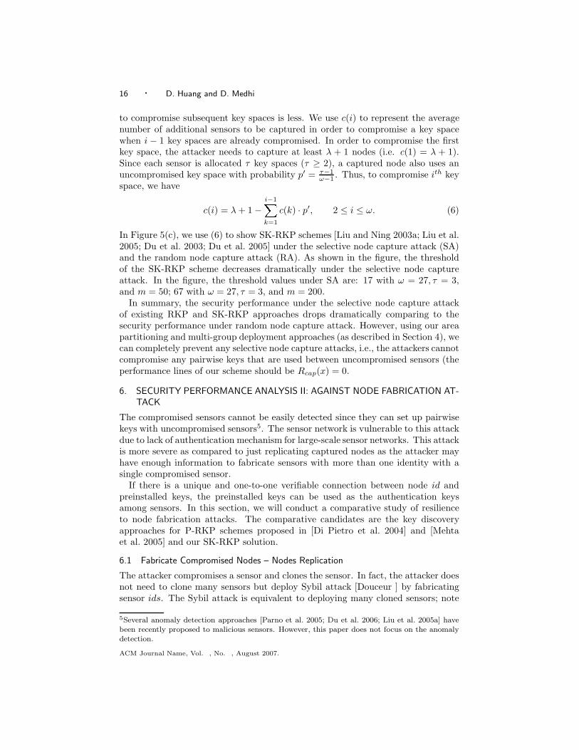
The heuristic method is as follows. Initially, when i = 0, an attacker can arbitrar-ily capture a sensor and derive m keys preinstalled in the captured sensor and then,Cx = m. Then, he inspects B: if B ≥ 1, he continuously captures the nodes withm− i keys that are not already compromised, and for each capture, Cx is increasedby m − i; if B < 1, he increases i by 1 until B ≥ 1. He then captures the sensorswith m − i keys that are not already compromised. The attacker continues thisprocess until the condition m = i is fulfilled or the entire key pool is compromised.The condition B > 1 means there exists uncompromised sensors that have m − ikeys which are not already compromised. Figure 5(a) and 5(b) show the compari-son between the selective-node-capture attack (SA) and random-node-capture attack(RA) to P-RKP schemes when m = 50 and m = 200. The comparative studiesshow that the selective node capture attack can gain more information than therandom node capture attack with the same number of captured sensors.
In the SK-RKP scheme, the attacker can selectively capture sensors that possesskeys within the same key space. Once λ+1 sensors in a key space are compromised,all the keys in that key space are compromised. In this fashion, an attacker canincrementally capture the sensors that use the same key space. Since sensors possesskeys from more than one key space, the number of sensors required to be captured
ACM Journal Name, Vol. , No. , August 2007.
16 · D. Huang and D. Medhi
to compromise subsequent key spaces is less. We use c(i) to represent the averagenumber of additional sensors to be captured in order to compromise a key spacewhen i − 1 key spaces are already compromised. In order to compromise the firstkey space, the attacker needs to capture at least λ + 1 nodes (i.e. c(1) = λ + 1).Since each sensor is allocated τ key spaces (τ ≥ 2), a captured node also uses anuncompromised key space with probability p′ = τ−1
ω−1 . Thus, to compromise ith keyspace, we have
c(i) = λ + 1 −i−1Xk=1
c(k) · p′, 2 ≤ i ≤ ω. (6)
In Figure 5(c), we use (6) to show SK-RKP schemes [Liu and Ning 2003a; Liu et al.2005; Du et al. 2003; Du et al. 2005] under the selective node capture attack (SA)and the random node capture attack (RA). As shown in the figure, the thresholdof the SK-RKP scheme decreases dramatically under the selective node captureattack. In the figure, the threshold values under SA are: 17 with ω = 27, τ = 3,and m = 50; 67 with ω = 27, τ = 3, and m = 200.
In summary, the security performance under the selective node capture attackof existing RKP and SK-RKP approaches drops dramatically comparing to thesecurity performance under random node capture attack. However, using our areapartitioning and multi-group deployment approaches (as described in Section 4), wecan completely prevent any selective node capture attacks, i.e., the attackers cannotcompromise any pairwise keys that are used between uncompromised sensors (theperformance lines of our scheme should be Rcap(x) = 0.
6. SECURITY PERFORMANCE ANALYSIS II: AGAINST NODE FABRICATION AT-
TACK
The compromised sensors cannot be easily detected since they can set up pairwisekeys with uncompromised sensors5. The sensor network is vulnerable to this attackdue to lack of authentication mechanism for large-scale sensor networks. This attackis more severe as compared to just replicating captured nodes as the attacker mayhave enough information to fabricate sensors with more than one identity with asingle compromised sensor.
If there is a unique and one-to-one verifiable connection between node id andpreinstalled keys, the preinstalled keys can be used as the authentication keysamong sensors. In this section, we will conduct a comparative study of resilienceto node fabrication attacks. The comparative candidates are the key discoveryapproaches for P-RKP schemes proposed in [Di Pietro et al. 2004] and [Mehtaet al. 2005] and our SK-RKP solution.
6.1 Fabricate Compromised Nodes – Nodes Replication
The attacker compromises a sensor and clones the sensor. In fact, the attacker doesnot need to clone many sensors but deploy Sybil attack [Douceur ] by fabricatingsensor ids. The Sybil attack is equivalent to deploying many cloned sensors; note
5Several anomaly detection approaches [Parno et al. 2005; Du et al. 2006; Liu et al. 2005a] havebeen recently proposed to malicious sensors. However, this paper does not focus on the anomalydetection.
ACM Journal Name, Vol. , No. , August 2007.

Secure Pairwise Key Establishment in Large-scale Sensor Networks · 17
that in this paper, we do not differentiate the difference between a Sybil attack anda node-fabrication attack. Due to lack of a-priori knowledge of post-deploymentconfiguration, uncompromised sensors cannot detect the cloned sensor as an anoma-lous sensor. This attack can have more severe consequences as compared to thepassive listening attacks on communication links between uncompromised nodes,since the attacker can implant malicious codes in replicated sensors to malfunctionthe PKE protocol. This is a typical form of an insider attack which will be discussedfurther in Section 7.
6.2 Fabricate Uncompromised Nodes
In this attack, the attacker compromises only few sensors and uses the capturedkeys to fabricate sensors with new identities. Then, the attacker can deploy thefabricated nodes in the network. The uncompromised sensors in the network cannotdetect the fabricated nodes as anomalous nodes as long as they can set up pairwisekeys with them. This attack is more severe as compared to passive eavesdroppingattack as the attacker may have enough information to fabricate many sensors withmany different identities and possibly outnumber the original set of sensors.
6.2.1 Node fabrication attack to P-RKP scheme. The attacker can launch thenode fabrication attack on the P-RKP scheme by capturing only a few sensors.Since there is no identity authentication in the P-RKP scheme [Eschenauer andGligor 2002; Chan et al. 2003], by capturing two nodes, the attacker can fabricateand deploy
�2mm
�new nodes without being detected. These fabricated nodes are
apparently good nodes, since they all have valid keys. Thus, the fabricated nodescan quickly outnumber the uncompromised nodes. To mitigate node fabricationattack, Di Pietro et al. [Di Pietro et al. 2004] and Mehta et al. [Mehta et al. 2005]proposed using a one-way function to distribute and discover the shared keys. Thebasic idea behind their approaches is to use a node id as the input to a one-wayfunction multiple times and the generated chain values modulo the size of key poolcan be used to identify the key id in the key pool. Using an one-way functionto identify the keys can be used in both the key predistribution phase and keydiscovery phase. Mehta et al. [Mehta et al. 2005] use simulation to prove thismethod is equivalent to randomly selecting keys from a large key pool. In this way,a connection is built between the node id and preinstalled keys via the one-wayfunction. As a result, attackers cannot arbitrarily fabricate sensors since they mustpossess the preinstalled keys that are identified by the hash-chain values.
Although one-way function based key discovery approaches can mitigate the nodefabrication attack, the attackers can still fabricate sensors without being detected.To fabricate a sensor, the attacker must compromise enough sensors to find a nodeid that can be used to set up communication links with uncompromised nodes. Inorder to connect to the network via an uncompromised node, the fabricated nodeneeds to satisfy the following conditions: (a) it should share the required numberof keys with the uncompromised node when q-composite scheme is used; (b) if thecondition (a) is satisfied, all shared keys not only must be known to the attacker,but also they must be in the right sequence. The probability that a fabricated node
ACM Journal Name, Vol. , No. , August 2007.

18 · D. Huang and D. Medhi
67100 200 300 400 500 600 700 800 900 10000
0.1
0.2
0.3
0.4
0.5
0.6
0.7
0.8
0.9
1
Number of compromised nodes
Fra
ctio
n of
unc
ompr
omis
ed n
odes
that
can
be
used
by
the
fabr
icat
ed n
odes
to c
onne
ct to
the
netw
ork
one−way function q=3one−way function q=2one−way function q=1SK−RKP ω=27 τ=3
x
Fig. 6. Node fabrication attack to one-way function key discovery approach and SK-RKP ap-proach: m = 200, ω = 27, τ = 3, p1 = 0.3.
satisfies the above two conditions with x captured nodes is computed as:
pf (x) =1
pconnect
mXi=q
�Pm
��mi
��P−mm−i
��Pm
�2 �Cx
P
�i
, (7)
wherePm
i=q
(Pm)(m
i )(P−mm−i )
(Pm)2 is the probability that i keys are shared between two
nodes, Cx = [1 − (1−m
P)x]P is the number of keys compromised due to capture of
x nodes, x is the number of captured nodes, thus (Cx/P )i = ([1− (1− mP )x])i is the
probability that all i keys are compromised due to x captured nodes, and pconnect
is the probability of node connectivity for q-composite schemes given in (8):
pconnect = p(q) + p(q + 1) + . . . + p(m), (8)
where p(q) is the probability that two nodes have exactly q keys in common. Theprobability p(q) is presented in [Chan et al. 2003] and is given as:
p(q) =
�Pq
��P−q
2(m−q)
��2(m−q)
m−q
��Pm
�2 .
Using (7) we draw the Figure 6. It shows the fraction of uncompromised nodes thatcan be used by fabricated nodes to connect to the system when q = 1, 2, 3. Sincethe one-way function key discovery approach cannot totally prevent the attackerfrom fabricating new nodes and the derived shared key is not unique, we cannotuse the direct key of the P-RKP scheme for authentication purpose.
6.2.2 Node Fabrication Attack to the SK-RKP scheme. The SK-RKP scheme isalso vulnerable to the node fabrication attack. However, there are some restrictionsfor the attacker. First, the attacker is required to capture more than λ sensors inorder to compromise a key space. Second, the attacker cannot arbitrarily generatenew ids for the fabricated sensors, since the ids indicate the rows of the key matrixA. The wrong id cannot set up the pairwise key between the fabricated sensor and
ACM Journal Name, Vol. , No. , August 2007.

Secure Pairwise Key Establishment in Large-scale Sensor Networks · 19
0.1 0.2 0.3 0.4 0.5 0.6 0.7 0.8 0.90
0.2
0.4
0.6
0.8
1
Single path success probability q
Psu
cc
(5,3)
0.1 0.2 0.3 0.4 0.5 0.6 0.7 0.8 0.90
0.2
0.4
0.6
0.8
1
Single path success probability q
Psu
cc
(6,4)
(a) Up to 1 faulty paths.
0.1 0.2 0.3 0.4 0.5 0.6 0.7 0.8 0.90
0.2
0.4
0.6
0.8
1
Single path success probability q
Psu
cc
(9,5)(7,5)
0.1 0.2 0.3 0.4 0.5 0.6 0.7 0.8 0.90
0.2
0.4
0.6
0.8
1
Single path success probability q
Psu
cc
(10,6)(8,6)
(b) Up to 2 faulty paths.
0.1 0.2 0.3 0.4 0.5 0.6 0.7 0.8 0.90
0.2
0.4
0.6
0.8
1
Single path success probability q
Psu
cc
(13,7)(11,7)(9,7)
0.1 0.2 0.3 0.4 0.5 0.6 0.7 0.8 0.90
0.2
0.4
0.6
0.8
1
Single path success probability q
Psu
cc
(14,8)(12,8)(10,8)
(c) Up to 3 faulty paths.
0.1 0.2 0.3 0.4 0.5 0.6 0.7 0.8 0.90
0.2
0.4
0.6
0.8
1
Single path success probability q
Psu
cc
(17,9)(15,9)(13,9)(11,9)
0.1 0.2 0.3 0.4 0.5 0.6 0.7 0.8 0.90
0.2
0.4
0.6
0.8
1
Single path success probability q
Psu
cc
(18,10)(16,10)(14,10)(12,10)
(d) Up to 4 faulty paths.
Fig. 7. Evaluate multi-path success probability Psucc given the number of faultypaths is up to 1, 2, 3, and 4.
the uncompromised sensor. If we restrict the number of distributed rows of a keymatrix A to no more than λ, we can prevent the node fabrication attack. Evenif the attacker can compromise all deployed sensors, he cannot derive new rows ofany key matrix. The previous proposals [Liu and Ning 2003a; Liu et al. 2005; Duet al. 2003; Du et al. 2005] cannot fulfil this requirement due to large size of sensornetworks. For example, if we stay with the restriction that no more than λ rows ofany key space are allowed to be distributed to sensors, for given ω, τ , and λ, themaximum number of sensors that can be deployed is λ·ω
τ . We can easily derive thatthe supported network size nz is linearly increased with respect to the increase ofthe λ.
6.3 Countermeasures to Node Fabrication Attack
In Figure 6, using the SK-RKP scheme, zero fraction of the network is compromisedwhen x = 0 ∼ 67. This property of the SK-RKP scheme allows us to design anauthentication protocol for the key discovery phase. Recall from Section 6.2.2 thatto restrict the number of sensors that are allowed to install keys from a given keyspace, the size of supported network is also restricted. Thus, if we partition a
ACM Journal Name, Vol. , No. , August 2007.

20 · D. Huang and D. Medhi
0.1 0.2 0.3 0.4 0.5 0.6 0.7 0.8 0.90
0.1
0.2
0.3
0.4
0.5
0.6
0.7
0.8
0.9
1
Single path success probability q
Psu
cc
(17,9)(13,7)(9,5)(5,3)
Fig. 8. Success probabilities for (17, 9), (13, 7), (9, 5), and (5, 3) RS multi-path coding schemes.
large sensor network into multiple small areas, we can utilize the perfect securityproperty of the SK-RKP scheme within each zone.
Note that in Section 4, we have proposed to use a unique structured key poolfor each zone and to restrict at most λ rows of a key space that are distributed tosensors. Our scheme is resilient to node fabrication attacks (including node repli-cation attacks) due to the following two facts: (a) Since no more than λ key rowsare distributed to sensors within a zone, attackers cannot fabricate uncompromisedsensors. Thus, attackers can only replicate captured sensors. (b) Since the key ma-trix used for one zone is different from the other zones, the attacker cannot deploythe replicated sensors to the other zones. Thus, the replication attack is restrictedwithin a relatively small area, i.e., the replicated nodes can only setup pairwise keyswith uncompromised sensors within the zone where it was captured.
7. SECURITY PERFORMANCE ANALYSIS III: AGAINST INSIDER ATTACK
An important question that we want to answer is: “in what scenarios, do we wantto use multi-path routing instead of single path routing?” In other words, “whatis the condition when multi-path routing is preferred over single-path routing?”To see this, we need to evaluate the multi-path success probability Psucc, giventhe single path success probability q and the number of paths. We have found anevaluation model developed by Tsirigos and Hass [Tsirigos and Haas 2004] to beapplicable to our scenario. When uniform codeword allocation is applied, we have:
Psucc =nX
i=k
�n
i
�pi(1 − p)n−i, (9)
where (n, k) is the Reed-Solomon coding scheme and p is the probability that areceiver successfully receives a codeword from a path.
IN our analysis, we assume that each path has the same success probabilityq = 0.1, . . . , 0.9, and that exactly one codeword is sent through a path; we considerthe number of faulty paths to be 1, 2, 3, and 4. In Figure 7(a)∼Figure 7(d), we plotsuccess probabilities Psucc of the total number of paths from 3 paths to 10 paths.
ACM Journal Name, Vol. , No. , August 2007.

Secure Pairwise Key Establishment in Large-scale Sensor Networks · 21
We have the following observations:
—Using Reed-Solomon codes, we can use the majority rule to filter out bad paritycodes. Thus, A 4-path multi-path routing does not give any benefit compared toa 3-path multi-path routing. We observe similar behavior with 6 and 5 paths, 8and 7 paths, 10 and 9 paths. This is since faulty nodes on different paths cancollude to generate the same parity codes, and it can create uncertainty at thedestination node.
—The success probability of the even number of paths is always lower than thatfor the corresponding odd number of paths. Thus, we use odd number of pathsin our schemes.
—Using our (n, k) Reed-Solomon multi-path coding scheme, we observe that biggerthe value of n results in Psucc to be higher when the number of paths k is fixed.
In order to decide whether to apply multi-path routing or single path routing, weplot the success probabilities for (17, 9), (13, 7), (9, 5), and (5, 3) Reed-Solomonmulti-path coding schemes in Figure 8. When Psucc ≥ q, the performance ofmulti-path routing is better than single path routing. For example, if the (5, 3)Reed-Solomon coding scheme is used, we observe that the success probabilities q ofsingle-path routing are always greater than the corresponding multi-path successprobability Psucc when q < 0.5. The same behavior is observed in the cases of(17, 9), (13, 7), (9, 5), and (5, 3) Reed-Solomon multi-path coding schemes. Thus,in the case of uniform block allocation and uniform success probability distribution,we conclude that the multi-path routing is preferred to single path routing whenthe number of paths increases and path success probability q > 0.5.
It may be noted that the adversaries can intentionally capture sensors located atarea borders to compromise the PKE procedures. However, based on our analysis inSection 8.1.2, the border sensors can also have high probabilities to set up multiple2-hop paths to the neighbor zone. In addition, our proposed multi-path PKEscheme can relieve the insider attacks due to compromised nodes.
8. OPERATIONAL PERFORMANCE ASSESSMENTS
8.1 Local Key Graph Connectivity
We now present the Local Key Graph connectivity analysis for sensors locatedwithin the same zone and in adjacent zones. Our analysis is based on the followingassumptions:
—The area covered is a two-dimensional Cartesian plane. A zone is representedby an area x ∈ [0, a], y ∈ [0, a], where (x, y) is a point in the two-dimensionalCartesian plane.
—All sensors have equal communication radius, R, and hence cover the same sizeof area, where R ≤ a/2.
—The sensors are uniformly distributed in a deployment region and the averagenumber of neighbors for each sensor is n′. The density of the deployed sensors isρ = n′
πR2 .
According to the assumption presented above, the number of deployed sensors
within each zone is nz = a2ρ ≈
a2n′
πR2
£. For our analysis, we consider R = 40
ACM Journal Name, Vol. , No. , August 2007.

22 · D. Huang and D. Medhi
meters, and a = 100 meters.Sensor Coverage – within the Same ZoneWe first consider the coverage of sensor [(i, j), b] in its zone Z(i, j). Given a position(x, y) for sensor [(i, j), b], the sensor coverage is given as follows:
Cb(i, j)|(x,y) =
¨C1
b (i, j)|(x,y) , 0 ≤p
x2 + y2 ≤ R;
C2b (i, j)|(x,y) , R <
px2 + y2 ≤ a/2.
The expressions for C1b (i, j) and C2
b (i, j), along with the proofs are given in Ap-pendix C. From these results, the number of neighbors of sensor [(i, j), b] withinthe zone Z(i, j) can be obtained as:
Nb(i, j) = ρ · Cb(i, j), (10)
where Nb(i, j) is the number of neighbors of sensor [(i, j), b] within the zone Z(i, j).In Figure 9(a), we show the contour curves of the average number of neighbors ofsensor [(i, j), b] within the zone Z(i, j).Sensor Coverage – in Different ZoneIn Figure 9(a), we show that there are 8 possible zones surrounding zone Z(i, j).We use superscripts + and − to represent the area coverage and sensor coveragebetween two neighboring zones. For example Cb(i
+, j−) and Nb(i+, j−) represent
the area coverage and sensor coverage of sensor [(i, j), b] in zone Z(i + 1, j − 1).Similarly, Cb(i, j
−) and Nb(i, j−) represent the area coverage and sensor coverage
of sensor [(i, j), b] in zone Z(i, j − 1). The number of neighbors that node [(i, j), b]covers in a neighboring zone is given as:
Nb(i∗, j∗) = ρ · Cb(i
∗, j∗), (11)
where * represents -, +, or none. The representations and proofs of neighboringzone coverage Cb(i
∗, j∗)|(x,y) are given in Appendix D.
8.1.1 Local Key Graph Connectivity within the Same Zone . The number ofkeys preinstalled in each sensor is represented by m. According to the deploymentpattern shown in Figure 4, we select a unique key pool for each zone, i.e., P(i, j)for Z(i, j). To determine the size of key pool (i.e., |P(i, j)|) and the number of keysselected (i.e., m = (λ + 1)τ and will be discussed in section 8.3) from the key poolfor sensor [(i, j), b], we use the equations of P-RKP scheme proposed by Eschenauerand Gligor [Eschenauer and Gligor 2002] and further modified for SK-RKP schemeby Du et al. [Du et al. 2003]:
p1 = 1 −�ω
τ
��ω−ττ
��ωτ
�2 = 1 − ((ω − τ)!)2
(ω − 2τ)!ω!, (12)
where p1 is the probability that given two sensors share at least one key.For sensor [(i, j), b] in zone Z(i, j), the number of neighbors within its zone is
Cb(i, j). As shown in Figure 9(a), if the average number of neighbors of a sensor, n′,is 50, the zone has total of nz = (n′a2)/(πR2) sensors and there are approximately11 nodes in the zone with less than 25 neighbors from the same zone. If we assumethe number of neighbors of a sensor is 25, using the local key graph6 connectivity
6Here, the local key graph is composed by the sensors within the same zone.
ACM Journal Name, Vol. , No. , August 2007.

Secure Pairwise Key Establishment in Large-scale Sensor Networks · 23
0 10 20 30 40 50 60 70 80 90 1000
10
20
30
40
50
60
70
80
90
100
1515
1515
2020
2020
25
25
25
25
25
25
25
25
30
30
30
30
30
30
30
30
35
35
35
35
35
35
35
40
40
40
40
40
40
45
45
45
45
45
Z(i−1,j) Z(i−1,j−1)
Z(i,j−1)
Z(i+1,j−1) Z(i+1,j) Z(i+1,j+1)
Z(i,j+1)
Z(i−1,j+1)
50 50
50 50
(a) Contour curves for average number of neighborswithin the same zone (n = 50, nz = 100).
0 5 10 15 20 25 30 35 400
5
10
15
20
25
30
35
40
R
R
0.1
0.1
0.2
0.3
0.3
0.4
0.4
0.5
0.6
0.7
0.7
0.8
0.8
0.9
0.1
0.1
0.1
0.1
0.2
0.2
0.2
0.3
0.3
0.3
0.4
0.4
0.4
0.5
0.5
0.5
0.6
0.6
0.6
0.7
0.7
0.7
0.8
0.8
0.9
0.9
Z(i+1,j−1)
Z(i,j−1)
(b) Probability contour curves to zoneZ(i + 1, j − 1) and zone Z(i, j − 1).
0 5 10 15 20 25 30 35 400
5
10
15
20
25
30
35
40
R
R
3
3
3
2
2
22
2
11
1
1
1
Z(i+1,j)
Z(i+1,j−1)
(c) Connectivity contour curves to theneighboring zone Z(i +1, j − 1) and zoneZ(i, j − 1) with q=1, 2, 3. The probabil-ity pq(i∗, j∗) to share at least q keys is0.8, see (14).
Fig. 9. In this example, sensors are deployed in a 100× 100 square meters area andall sensors have the same transmission radius (40m).
presented in [?], we derive the probability p1 = 0.5. When p1 ≥ 0.5, the localkey graph is connected with probability greater than 0.996 within three hops. Inthe worst case, the sensor is located at the corner of the square area, and hasapproximately 12 neighbors within the same zone. In this case, the probabilitythat the local key graph is connected within five hops is 0.8736.
8.1.2 Local Key Graph Connectivity between Two Adjacent Zones. The node[(i, j), b] may be located close to the boundary of two neighboring zones, Z(i, j)and Z(i∗, j∗). The number of neighbors of node [(i, j), b] located within these twozones can be represented by Nb(i, j) and Nb(i
∗, j∗). Node [(i, j), b] is considered tobe connected to the neighboring zone as long as it can find at least one neighbor,
ACM Journal Name, Vol. , No. , August 2007.

24 · D. Huang and D. Medhi
b′, located in Cb(i, j) who shares a key with at least one of nodes, b′′, located inCb(i
∗, j∗). Using (10) and (11), we can derive the probability p(i∗, j∗) that sensor[(i, j), b] can connect to the neighboring zone with the help of all its neighbors.
p(i∗, j∗) = 1 −
�nz −Nb(i, j)Nb(i
∗, j∗)
��nz −Nb(i
∗, j∗)Nb(i, j)
��nz
Nb(i∗, j∗)
��nz
Nb(i, j)
� . (13)
Note that (10) and (11) are derived from Cb(i, j) and Cb(i∗, j∗), which are the
functions of two-dimensional Cartesian coordinates with the position (x, y). Thusp(i∗, j∗) is the function of (x, y). Using the (13), we draw the probability contourcurves in Figure 9(b), where a node in Z(i, j) can connect to its neighboring zonesZ(i, j−) and Z(i+, j−) with parameters a = 100m, R = 40m, n′ = 50, nz = 100.
8.1.3 Multi-path Connectivity between Neighboring Zones. Figure 9(b) showsthe contour curves of the probabilities that a node in Z(i, j) can connect to itsneighboring zones Z(i, j − 1) and Z(i + 1, j − 1). The probability that a nodecan connect to neighboring zones with the help of exactly k neighbors is given asfollows:
pk(i∗, j∗) =
�nzk
�� nz −Nb(i, j)Nb(i
∗, j∗) − k
��nz −Nb(i
∗, j∗)Nb(i, j) − k
��nz
Nb(i∗, j∗)
��nz
Nb(i, j)
� .
The probability that a node can connect to neighboring zones with the help of atleast q neighbors is denoted by pq(i
∗, j∗) and is given as follows:
pq(i∗, j∗) = 1 − [p0(i
∗, j∗) + · · · + pq−1(i∗, j∗)] . (14)
Figure 9(c) shows the range in which a sensor can connect to its neighboring zoneswith at least q links via its neighbors, where q = 1, 2, 3 and the connectivity prob-ability is 0.8. Thus, a sensor can randomly select q neighbors that respond to therequests and send the responses to the destination nodes. The selected q destina-tion nodes can help the sensor set up q paths to any of the neighbors in the adjacentzone. Thus, we can apply our proposed multi-path PKE scheme (see section 4.5.1)to set up the pairwise keys.
Comparing Figure 9(a) and Figure 9(c), almost all sensors that have less than 20neighbors and some of sensors that have less than 25 neighbors can set up at threeconnections to the diagonal neighboring zones. The sensors that have less than 35neighbors within the same zone may set up at three connections to the horizontaland vertical neighboring zones.
8.2 Communication Overhead Analysis
Here, we will derive the mathematical expressions for the probability that a sensorcan set up key paths with all its neighbors within h hops in [?]. Since our key estab-lishment procedure includes two phases, the key establishment within a zone andthe key establishment between two adjacent zones, we analyze the communicationoverhead for each phase separately.
During the first phase of key establishment, the closer the sensor to the centerof a zone, the smaller the communication overhead due to key establishment. For
ACM Journal Name, Vol. , No. , August 2007.

Secure Pairwise Key Establishment in Large-scale Sensor Networks · 25
example, for τ = 2, ω = 7, the following table shows the number of hops and thecorresponding local key graph connectivity probabilities: As shown in Figure 9(a),
Table III. The relation between the neighborhood size and the length of a key path.# of neighbors # of hops local key graph connectivity
50 2 0.995740 2 0.980630 3 0.999625 3 0.998020 3 0.989315 4 0.9583
most pairwise keys can be set up within 3 hops. Since the communication over-head is proportional to the number hops of a path, the communication overhead isamplified due to multipath PKE scheme. As we can see in Table III, the denserthe network, the shorter the key paths when the probability (i.e., p1; see (12)) ofsharing preinstalled keys is given.
During the second phase of key establishment, between two adjacent zones, asshown in Figure 9(c), a sensor can set up q paths to the neighboring zones withthe probability of 0.8. Each path is a 2-hop path. A sensor applies (n, k) Reed-Solomon coding and partitions a pairwise key in q portions (where n = q), andthen sends them via q key paths. If the destination correctly receives l codewordswhere l ≥ k or l ≤ (n − k)/2, the pairwise key can be successfully set up, since allmultipath to the neighboring zone is restricted by 2 hops. Thus, the communicationoverhead is only doubled compared to one-hop communications. In addition, thetotal communication overhead is also proportional to the number of paths.
8.3 Storage Overhead
Our proposed RKP-PKE scheme utilizes the key predistribution scheme proposedby Blom [Blom 1985] (for detailed description, see Appendix A). The scheme isbuilt on two matrices: a publicly known matrix G of size (λ + 1) × N ; a secretmatrix D of size (λ + 1) × (λ + 1) created by key distribution center. The matrixA of size N × (λ + 1) is then created as A = (D · G)T . Each row of A is thekeys distributed to a sensor and the row number can serve as a sensor’s id. Ourapproach requires each sensor to select τ key spaces (see section 4.2.1). Thus, asensor is required to store m = (λ + 1)τ keys that are used to set up pairwise keyswithin its zone, where λ is restricted by nz = λω/τ . For example, if τ = 2, ω = 7,and nz = 100, then λ = 29. In addition to the keys selected from the key matrixA, each sensor is required to install at least one shared key with a unique sensorin each of its neighboring zones. The maximum number of neighboring zones is 8.Thus, the total number of keys that are needed to be preinstalled in a sensor isgiven as:
m =�lnzτ
ω
m+ 1�
τ + γα,
where γ is the number of neighboring zones and α is the number of keys preinstalledfor each pair of neighboring zones for a sensor. For all our analysis, we use the
ACM Journal Name, Vol. , No. , August 2007.

26 · D. Huang and D. Medhi
following parameter setting: γ = 8, α = 1. Thus, the storage requirement for asensor is m = 68.
Unlike the P-RKP scheme proposed in [Eschenauer and Gligor 2002] which re-quires m = 272 to fulfil p1 = 0.5238, our scheme requires m = 68 which is muchless. For the scheme specified in [Du et al. 2004], to achieve the p1 = 0.5238, itrequires 72 keys preinstalled for each sensor, which is a marginally higher than ourscheme.
Our approach is similar to the group key based solution proposed by Liu etal. [2005b]. In [Liu et al. 2005b], the key predistribution is based on a two-dimensional group structure where two instances of key distributions D and D′
are applied to the vertical structure and horizontal structure, respectively. Thus,the storage requirement equals to the summation of key storage required by bothD and D′; and we have |D| + |D′| = m, where m is the maximum storage al-located for storing keys. In our approach, we assume D is the SK-RKP schemeand D′ is a deterministic key predistribution approach which requires the constantnumber of keys (i.e., ≤ 8) to be installed; and we have the relation |D| + 8 = m.Since |D| ≈ |D′| in [Liu et al. 2005b], our approach saves approximately 50% spacewhen the group size is large. This advantage is due to the pre-known deploymentinformation of our approach.
8.4 Computational Overhead Analysis
The computational overhead arises mainly from the secure group key scheme in-troduced by SK-RKP scheme. In our schemes, we reduced the computational over-head significantly as compared to the SK-RKP schemes proposed in [Liu and Ning2003a; Liu et al. 2005; Du et al. 2003; Du et al. 2005] that do not use the locationinformation. For example, by using the SK-RKP scheme without using locationinformation, for m = 200, τ = 2, and λ = 100, to derive a pairwise key, the totalnumber of required modular multiplication operations is 200 (for the detail descrip-tion of pairwise key establishment scheme refer to [Liu and Ning 2003a; Liu et al.2005; Du et al. 2003; Du et al. 2005]). In our scheme, we only need to guaranteethe local connectivity within a zone. We reduce the number of keys preinstalled ina sensor (see the analysis presented in section 8.3). If we restrict the number of sen-sors within a zone to nz = 100, then λ = ⌈nzτ/ω⌉ = 29 where ω = 7, τ = 2. Thus,the number of required modular multiplication operations to derive a pairwise keyis only 58.
Finally, we note that public key cryptography algorithms (such as ECC and RSA)have been implemented in sensors. A general technique to improve the performanceof public key algorithm is to reduce the Hamming weight of a multiplier (an ex-ponent in RSA). According to [Koc 1994], the average number of multiplicationsinvolved by RSA scheme is 3
2 (k − 1), where k is the number bits of an exponent.Thus, for 1024-bit RSA scheme, it requires about 1535 modular multiplications. Ac-cording to Gura et al. [2004], in a projective coordinate system, a point additionrequires 9 multiplication and 5 squaring operations, and point doubling requires 4multiplication and 4 squaring operations as the most expensive operations. If weassume that the average number of multiplications of a point addition requires 5multiplications, for a 160-bit ECC point multiplication operation, 3
2 (k−1)·5 = 1193modular multiplications are required. Thus, public key based schemes involve more
ACM Journal Name, Vol. , No. , August 2007.

Secure Pairwise Key Establishment in Large-scale Sensor Networks · 27
computational overhead compared to our proposed approaches.
9. CONCLUSION
We have proposed a five phase RKP-PKE solution to counter various sensor networkattacks. Our approach has benefitted from three schemes: the λ-restricted SK-RKPscheme, multiple group/zone sensor deployment, and a Reed-Solomon code-basedk-path PKE protocol. We utilize the initial threshold of the SK-RKP scheme andthe unique relation between key ring id and predistributed keys to guard againstselective node capture and node fabrication attacks. RKP-PKE schemes are vulner-able to insider attack. We utilize the multiple groups/zones to restrict the insiderattacks within a relative small range; and we use the multiple node-disjoint-pathPKE protocol and fault-tolerance coding scheme (Reed-Solomon codes) to improvethe system resilience to insider attacks.
RKP-PKE schemes have been studied extensively in recent years, but it is still inits infancy stage since many security and implementation problems have not beensolved yet. For example, an insider attack is still the biggest threat for RKP-PKEschemes and no efficient solutions have been found to prevent it; a comprehensivestudy of multipath coding schemes is required; anonymity issues of wireless sensornetworks; secure rekeying and node replenishment need to be studied; various sensordeployment methods—hybrid sensor distribution patterns—need to be studied; noPKE protocol prototype has been built and the security services of PKE protocolsuch as confidentiality, integrity, and authenticity are still unclear. It is hoped thatthis work can serve as an elicitation for researchers interested in further investigationinto this vital area.
REFERENCES
Akyildiz, I. F., Su, W., Sankarasubramaniam, Y., and Cayirci, E. 2002. A Survey on SensorNetworks. IEEE Communications Magazine 40, 102 – 114.
Blom, R. 1985. An Optimal Class of Symmetric Key Generation Systems. In EUROCRYPT’84.Lecture Notes in Computer Science, vol. 209. Springer-Verlag, Paris, France, 335–338.
Blundo, C., Santis, A. D., Herzberg, A., Kutten, S., Vaccaro, U., and Yung, M. 1998.Perfectly-Secure Key Distribution for Dynamic Conferences. Information and Computa-tion 146, 1, 1–23.
Chan, H., Perrig, A., and Song, D. 2003. Random Key Predistribution Schemes for SensorNetworks. In Proceedings of 2003 Symposium on Security and Privacy. IEEE Computer Society,Los Alamitos, CA, 197–215.
Di Pietro, R., Mancini, L. V., and Mei, A. 2004. Efficient and Resilient Key Discovery Basedon Pseudo-Random Key Pre-deployment. In Proceedings of 18th International Parallel andDistributed Processing Symposium (IPDPS). 217.
Douceur, J. R. The Sybil Attack. In Proceedings of First International Workshop on Peer-to-Peer Systems (IPTPS). 251–260.
Du, W., Deng, J., Han, Y. S., Chen, S., and Varshney, P. K. 2004. A Key ManagementScheme for Wireless Sensor Networks Using Deployment Knowledge. In Proceedings of IEEEInformation Communications Conference (INFOCOM). 586–597.
Du, W., Deng, J., Han, Y. S., Varshney, P., Katz, J., and Khalili, A. 2005. A Pairwise KeyPre-distribution Scheme for Wireless Sensor Networks. ACM Transactions on Information andSystem Security 8, 2, 228–258.
Du, W., Deng, J., Han, Y. S., and Varshney, P. K. 2003. A Pairwise Key Pre-distributionScheme for Wireless Sensor Networks. In Proceedings of 10th ACM Conference on Computerand Communications Security (CCS’03). 42–51.
ACM Journal Name, Vol. , No. , August 2007.

28 · D. Huang and D. Medhi
Du, W., Fang, L., and Ning, P. 2006. LAD: Localization Anomaly Detection for Wireless Sensor
Networks. Journal of Parallel and Distributed Computing 66, 7, 874–886.
Eschenauer, L. and Gligor, V. D. 2002. A Key-management Scheme for Distributed SensorNetworks. In Proceedings of 9th ACM Conference on Computer and Communication Security(CCS-02). 41–47.
Ganesan, D., Govindan, R., Shenker, S., and Estrin, D. 2001. Highly-resilient, Energy-efficientMultipath Routing in Wireless Sensor Networks. Mobile Computing and CommunicationsReview 4, 5, 11–25.
Gura, N., Patel, A., and Wander, A. 2004. Comparing Elliptic Curve Cryptography andRSA on 8-bit CPUs. In Proceedings of the 2004 Workshop on Cryptographic Hardware andEmbedded Systems (CHES). 119–132.
Huang, D. and Medhi, D. 2005. A Byzantine Resilient Multi-path Key Establishment Schemeand Its Robustness Analysis for Sensor Networks. In 5th IEEE International Workshop onAlgorithms for Wireless, Mobile, Ad Hoc and Sensor Networks. 240b.
Huang, D., Mehta, M., and Medhi, D. 2005. Source Routing Based Pairwise Key Establish-ment Protocol for Sensor Networks. In Proceedings of 24th IEEE International PerformanceComputing and Communications Conference. 177–183.
Huang, D., Mehta, M., Medhi, D., and Lein, H. 2004. Location-aware Key Management Schemefor Wireless Sensor Networks. In Proceedings of ACM Workshop on Security of Ad Hoc andSensor Networks (SASN). 29–42.
Kahn, J. M., Katz, R. H., and Pister, K. S. J. 1999. Next Century Challenges: Mobile Net-working for ”Smart Dust”. In Proceedings of International Conference on Mobile Computingand Networking (MOBICOM). 271–278.
Karlof, C. and Wagner, D. 2003. Secure Routing in Wireless Sensor Networks: Attacks andCountermeasures. Elsevier’s AdHoc Networks Journal, Special Issue on Sensor Network Ap-plications and Protocols 1, 2–3 (September), 293–315.
Koc, C. K. 1994. High-speed RSA implementation. Tech. rep., RSA Laboratories.
Lindsey, S. and Raghavendra, C. S. 2002. Pegasis: Power Efficient Gathering in Sensor Infor-mation Systems. In Proceedings of IEEE Aerospace Conference. 1125 –1130.
Liu, D. and Ning, P. 2003a. Establishing Pairwise Keys in Distributed Sensor Networks. InProceedings of 10th ACM Conference on Computer and Communications Security (CCS’03).52–61.
Liu, D. and Ning, P. 2003b. Location-based Pairwise Key Establishments for Static SensorNetworks. In Proceedings of the 1st ACM workshop on Security of ad hoc and sensor networks(CCS’03). 72 – 82.
Liu, D. and Ning, P. 2005. Improving Key Pre-Distribution with Deployment Knowledge inStatic Sensor Networks. to appear in ACM Transactions on Sensor Networks 2, 204–239.
Liu, D., Ning, P., and Du, W. 2005a. Detecting Malicious Beacon Nodes for Secure LocationDiscovery in Wireless Sensor Networks. In Proceedings of the The 25th International Conferenceon Distributed Computing Systems. 609–619.
Liu, D., Ning, P., and Du, W. 2005b. Group Based Key PreDistribution in Wireless SensorNetworks. In Proceedings of the ACM Workshop on Wireless Security (WiSe). 11–20.
Liu, D., Ning, P., and Li, R. 2005. Establishing Pairwise Keys in Distributed Sensor Networks.ACM Transactions on Information and System Security 8, 1, 41 – 77.
Manjeshwar, A. and Agrawal, D. P. 2001. TEEN: A Routing Protocol for Enhanced Efficiencyin Wireless Sensor Networks. In Proceedings of 15th International Parallel and DistributedProcessing Symposium (IPDPS) Workshops. 30189a.
Mehta, M., Huang, D., and Harn, L. 2005. RINK-RKP: A Scheme for Key Predistribution
and Shared-key Discovery in Sensor Networks. In Proceedings of 24th IEEE InternationalPerformance Computing and Communications Conference. 193–197.
Parno, B., Perrig, A., , and Gligor, V. 2005. Distributed Detection of Node ReplicationAttacks in Sensor Networks. In Proceedings of the IEEE Symposium on Security and Privacy.49–63.
ACM Journal Name, Vol. , No. , August 2007.

Secure Pairwise Key Establishment in Large-scale Sensor Networks · 29
Pottie, G. J. and Kaiser, W. J. 2000. Wireless Integrated Network Sensors. Communications
of the ACM 43, 5 (May), 51 – 58.
Reed, I. S. and Solomon, G. 1960. Polynomial Codes Over Certain Finite Fields. SIAM Journalof Applied Math 8, 300–304.
Sarwate, D. V. 1977. On the Complexity of Decoding Goppa Codes. IEEE Transactions onInformation Theory 23, 4, 515–516.
Spencer, J. H. 2001. The Strange Logic of Random Graphs (Algorithms and Combinatorics).Springer Verlag.
Tsirigos, A. and Haas, Z. J. 2004. Analysis of Multipath Routing Part I: The Effect on thePacket Delivery Ratio. IEEE Transactions on Wireless Communications 3, 1, 138–146.
Wicker, S. B. 1995. Error Control Coding for Digital Communication and Storage. Prentice-Hall, NJ.
Zhu, S., Xu, S., Setia, S., and Jajodia, S. 2003. Establishing Pair-wise Keys For Secure Com-munication in Ad Hoc Networks: A Probabilistic Approach. In Proceedings of 11th IEEEInternational Conference on Network Protocols (ICNP). 326–335.
Appendices
A. STRUCTURED KEY-POOL RANDOM KEY PREDISTRIBUTION SCHEME
SK-RKP scheme is a modified version of P-RKP scheme. The main differences arethe key pool structure and key discovery method. Unlike in P-RKP schemes, inSK-RKP scheme, each sensor is preloaded with a unique set of keys in its memory.The key discovery is not simply finding a shared key with the neighboring sensor,but using a set of polynomial variables (constructed by the keys possessed by thesensor) to derive the shared key. In addition, the key id can serve as the sensor idwhich is linked to the set of preinstalled keys.
The SK-RKP scheme uses the key predistribution scheme proposed by Blom [Blom1985]. This scheme allows any pair of nodes in a network to find a pairwise keyin a secure way as long as no more than λ nodes are compromised. The scheme isbuilt on two matrices over a finite field GF(q): a publicly known matrix G of size(λ + 1)×N ; a secret matrix D of size (λ + 1)× (λ + 1) created by key distributioncenter. The matrix A of size N × (λ + 1) is then created as A = (D · G)T over thefinite field GF(q). Each row of A is the keys distributed to a group member andthe row number can serve as a sensor’s id. Since K = A ·G is a symmetric matrix,nodes i and j can generate a shared key (Kij or Kji) from their predistributedsecrets, where Kij is the element in K located in the ith row and jth column.
A key pool is constructed by many key spaces, represented by A(t), where t =1, . . . , ω. Each sensor randomly selects τ key spaces out of ω key spaces, whereτ < ω. If sensor k selects key space A(t), the kth row of A(t) and kth column ofG are preinstalled in the sensor (note that the G matrix is unique). The SK-RKPscheme has following properties:
—Once two nodes i and j have keys preinstalled from the same key space A(t), they
can derive a shared key K(t)ij = K
(t)ji .
—If x rows of a key space A(t) are predistributed to x sensors and x ≤ λ, any subsetof the x sensors cannot collude to derive the secrets in other sensors.
ACM Journal Name, Vol. , No. , August 2007.

30 · D. Huang and D. Medhi
—The id of a sensor is represented by the row number of the key matrix A. No othersensor can impersonate this sensor, since the row of A is uniquely distributed tothis sensor.
The technical details refer to [Liu and Ning 2003a; Liu et al. 2005; Du et al. 2003;Du et al. 2005].
B. MULTI-PATH ALGORITHMS
Algorithm B.1 Encoding of RS Codes.1. let m(x) = m0 + m1x + · · · + mk−1x
k−1 be the message polynomial to beencoded, where mi ∈ GF (2q) and k = n − 2t.g(x) = (x+α)(x+α2) · · · (x+α2t) is a publicly known generator polynomial,where gi ∈ GF (2q) and g(x) has α, α2, . . . , α2t as roots.
2. Dividing x2tm(x) by g(x), we have x2tm(x) = a(x)g(x)+b(x), where b(x) =b0 + b1x + · · · + b2t−1x
2t−1 and b(x) is the parity check polynomial.Then c(x) = b(x) + x2t is the codeword polynomial for the message m(x)
Algorithm B.2 Decoding of RS Codes.1. c(x) = c0 + c1x + · · · + cn−1x
n−1
r(x) = r0 + r1x + · · · + rn−1xn−1
e(x) = e0 + e1x + · · · + en−1xn−1
where ci, ri, ei ∈ GF (2q), r(x) is received codeword, and e(x) = r(x) − c(x)is the error polynomial, where ei = ri − ci is a symbol in GF (2q).
2. Suppose e(x) has v errors at the locations; then, e(x) = ej1xj1 + ej2x
j2 +· · · + ejv
xjv .Faulty path can be identified by evaluating Si = r(x)|x=αi = r(αi), i =1, . . . , 2t, if Si 6= 0.The error-location numbers are Xj1 = αj1 , Xj2 = αj2 , · · · , Xjv
= αjv
Using Forney’s algorithm [Wicker 1995], the error values are Yl = ejl,
l = 1, . . . , v.3. To recover the the original message c(x), we have c(x) = r(x) − e(x).
C. SENSOR COVERAGE – WITHIN THE SAME ZONE
The covering area of sensor [(i, j), b] in its zone Z(i, j) is shown in Figure 10(a).We can further divide the zone into 4 areas. The sensor coverage in these 4 areasare horizontally and vertically mapped to each other. Within a small area, thereare two scenarios that shown in the Figure 10(a).
In the first scenario (shown the sensor is located at the position (x1, y1)), the
distance between the origin and the sensor isÈ
x21 + y2
1 ≤ R. The coverage is
composed by a sector with the angle θ1 plus two triangles (the shaded areas).
The θ1 = 32π − sin−1 B1−x1
R − sin−1 A1−y1
R , where, A1 − y1 =È
R2 − x21, and
B1 − x1 =È
R2 − y21 .
The coverage (the shade area) of sensor [(i, j), b] in zone Z(i, j) is represented asC1
b (i, j) and it is computed as follows:
C1b (i, j)|(x1,y1) = x1y1 +
1
2[x1(A1 − y1) +y1(B1 − x1)] +
θ1
2R2.
ACM Journal Name, Vol. , No. , August 2007.

Secure Pairwise Key Establishment in Large-scale Sensor Networks · 31
x
y
0
zone (i,j)zone (i,j-1)
zone (i+1,j)zone (i+1,j-1)
A1
B1
R
R
A2
B2B3
2
(x1,y1)1
(x2,y2)
a
a
34
5
A3
(a) Occupied zone.
����������������������Zone (i,j) Zone (i,j-1)
Zone (i+1,j-1)
Zone (i+1,j)
(x,y)
A 1
B 1
R
R ������������������������ Zone (i,j) Zone (i,j-1)
Zone (i+1,j-1)
Zone (i+1,j)
(x,y) R ��������������������������Zone (i,j) Zone (i,j-1)
Zone (i+1,j-1)
Zone (i+1,j)
(x,y)
R
R o
A 2 b A 3
A 1
A 2
A 3
B 1 B 2 B 3
A 4
B 3 B 2 B 1
A 1
A 2 b
o o x x x
y y y
(a) (b) (c)
b �������� B 4
(b) Zone coverage.
Fig. 10. Zone coverage among different zones.
In the second scenario (shown the sensor is located at the position (x2, y2)),
the distance between the origin and the sensorÈ
x22 + y2
2 > R. The coverage
is composed by two triangles (△A2A3o,△B2B3o) and two sectors with angles θ2
and θ3. The θ2 is given as θ2 = π2 − sin−1 x2−B3
R − sin−1 y2−A3
R . The θ3 is given as
θ3 = 32π−sin−1 B2−x2
R −sin−1 A2−y2
R . The θ4 and θ5 are given as θ4 = 2 sin−1 A2−y2
R
and θ5 = 2 sin−1 B2−x2
R , respectively. We note that y2 −A3 = A2 − y2 =È
R2 − x22
and x2 − B3 = B2 − x2 =È
R2 − y22 . The coverage (the shade area) of sensor
[(i, j), b] in zone (i, j) is represented as C2b (i, j) and it is computed as follows:
C2b (i, j)|(x2,y2) =
8>><>>: 12 [x2(A2 − A3) + y2(B2 − B3)] + θ2+θ3
2 R2 , x ≤ R, y ≤ R12x2(A2 − A3) + 2π−θ4
2 R2 , x ≤ R, y > R12y2(B2 − B3) + 2π−θ5
2 R2 , x > R, y ≤ R
πR2 , x > R, y > R.
D. SENSOR COVERAGE – IN DIFFERENT ZONES
D.1 Zone Coverage C(i, j−)
Shown in Figure 10(b)-(a), we first compute the area of the triangle △A3A1b =12 (|A1A2|+|A2A3|)|A2b|, where |A1A2| =
√R2 − x2, |A3b| = x
cos( 6 A3bA2)= xR√
R2−y2,
|A2A3| = xy√R2−y2
, and |A2b| =È|A3b|2 − |A2A3|2.
The area of triangle △A3oB1 = 12 |B1o||A3o|, where |B1A3| = R− |A3b|, |A3o| =
y − |A2A3|, and |B1o| =È|B1A3|2 − |A3o|2.
The area of sector úB1bA1 =6 A1bB1
2 R2, where 6 A2bA3 = sin−1�
yR
�, 6 A2A1b =
sin−1�
xR
�, 6 A1bA2 = π
2 − 6 A2A1b, and 6 A1bB1 = 6 A1bA2 + 6 A2bA3.
ACM Journal Name, Vol. , No. , August 2007.

32 · D. Huang and D. Medhi
Thus, the shade area C(i, j−) is given as:
Cb(i, j−)|(x,y) = úB1bA1 + △B1A3o −△A3A1b
=R2
2
hπ2
+ sin−1� y
R
�− sin−1
� x
R
�i− x
2
�pR2 − x2 +
xypR2 − y2
�+
1
2
�y − xyp
R2 − y2
�Ê�R − xRp
R2 − y2
�−�
y − xypR2 − y2
�.
D.2 Zone Coverage C(i+, j−)
Shown in Figure 10(b)-(b), we first compute the area of sector úB4bA4 = πR2
4 . Then,
we can derive the following relations: the area of sector úB1bA4 =sin−1( y
R )2 R2; the
area of triangle △bB1B3 = 12
pR2 − y2y; the area of sector úB4bA3 =
sin−1( xR )
2 R2;
the area of triangle △bA1A3 = 12
√R2 − x2x. The shade area C(i+, j−) is given as:
Cb(i+, j−)|(x,y)
= úB4bA4 − úB1bA4 −△bB1B3 − úB4bA3 −△bA1A3 + xy
=πR2
4− R2
2
hsin−1
� y
R
�+ sin−1
� x
R
�i− 1
2
�xp
R2 − x2 + yÈ
R2 − y2�
+ xy.
D.3 Zone Coverage C(i+, j)
Shown in Figure 10(b)-(c), we first compute the area of triangle △B3B1b = 12 (|B1B2|+
|B2B3|)|B2b|, where |B1B2| =p
R2 − y2, |B3b| = y
cos( 6 B3bB2)= yR√
R2−x2, |B2B3| =
xy√R2−x2
, and |B2b| =È|B3b|2 − |B2B3|2.
The area of triangle △B3oA1 = 12 |A1o||B3o|, where |A1B3| = R− |B3b|, |B3o| =
x − |B2B3|, and |A1o| =È|A1B3|2 − |B3o|2
The area of sector úA1bB1 =6 B1bA1
2π πR2 =6 B1bA1
2 R2, where 6 B2bB3 = sin−1�
xR
�,
6 B2B1b = sin−1�
yR
�, 6 B1bB2 = π
2 − 6 B2B1b, and 6 B1bA1 = 6 B1bB2 + 6 B2bB3.
Thus, the shade area C(i+, j) is given as follows:
Cb(i+, j)|(x,y) = úA1bB1 + △A1B3o −△B3B1b
=R2
2
hπ2
+ sin−1� x
R
�− sin−1
� y
R
�i− y
2
�ÈR2 − y2 +
xy√R2 − x2
�+
1
2
�x − xy√
R2 − x2
�Ê�R − yR√
R2 − x2
�−�x − xy√
R2 − x2
�.
ACM Journal Name, Vol. , No. , August 2007.