Embed Size (px)
Citation preview


FAA Approved Airplane Flight Manual Supplement Garmin Ltd. Or its subsidiaries Garmin GFC 700 AFCS and TAWS Option Mooney M20M/M20R
c/o Garmin International, Inc. 1200 E. 151st Street Olathe, Kansas 66062 U.S.A.
190-00638-00 Rev A Page 3 of 22FAA Approved
Table of Contents
SECTION PAGE
SECTION I – GENERAL 4SECTION II – LIMITATIONS 7SECTION III – EMERGENCY PROCEDURES 9SECTION IV – NORMAL PROCEDURES 14SECTION V – PERFORMANCE 19SECTION VI – WEIGHT AND BALANCE 20SECTION VII – SYSTEM DESCRIPTIONS 21SECTION VIII – HANDLING AND SERVICE 22

FAA Approved Airplane Flight Manual Supplement Garmin Ltd. Or its subsidiaries Garmin GFC 700 AFCS and TAWS Option Mooney M20M/M20R
c/o Garmin International, Inc. 1200 E. 151st Street Olathe, Kansas 66062 U.S.A.
190-00638-00 Rev A Page 4 of 22FAA Approved
SECTION I – GENERAL
1. The GFC 700 Automatic Flight Control System (AFCS) is a 2 axis autopilot and flight director system which provides the pilot with the following features: Altitude Preselect and Altitude Hold (ALT); Flight Level Change with Airspeed Hold (FLC); Vertical Speed Hold (VS); Navigation tracking for VOR (NAV) and GPS (GPS); Heading Hold (HDG); Approach mode coupling to VOR (VAPP) or localizer (LOC) and glideslope (GS); Back Course (BC) tracking; and Go Around (GA) pitch/roll guidance. The system consists of autopilot controls on the Multi-Function Display (MFD), servos with autopilot processing logic, Flight Director processing logic in the GIAs, a control wheel-mounted elevator trim switch, a control wheel-mounted trim interrupt and autopilot disconnect (A/P DISC/TRIM INTER) switch, a control wheel-mounted CWS (Control Wheel Steering) switch, a remote-mounted go-around switch, and PFD/MFD-mounted altitude preselect, heading, and course knobs.
2. The GFC 700 autopilot contains an electric pitch trim system which is used by the autopilot for automatic pitch trim during autopilot operation and by the pilot for manual electric pitch trim when the autopilot is not engaged. The manual electric pitch trim system is operated by a split switch on the pilot’s control wheel.
3. The GFC 700 autopilot and manual electric trim will not operate until the system has satisfactorily completed a preflight test. The preflight test begins automatically with initial power application to the aircraft and the A/P POWER switch set to the ON position.
4. The following conditions will cause the autopilot to disconnect:
Electrical power failure, including turning off the A/P POWER switch, which also serves as the autopilot circuit breaker.
Internal autopilot system failure
AHRS malfunction
Loss of Air Data Computer information
Depressing the red “A/P DISC/TRIM INTER” button on the pilot’s control wheel
Actuating the left (outboard) section of the manual electric trim split switch
Pushing the AP button on the autopilot mode controller when the autopilot is engaged
Pushing the GO AROUND button on the instrument panel
Pressing and holding the CWS (control wheel steering) switch on the left grip of the pilot’s control wheel will disconnect the autopilot servos from the airplane flight controls as long as the CWS switch is depressed. Upon release of the CWS switch, the system will synchronize to the existing pitch and roll modes selected. Review the GFC700 Cockpit Reference Guide for more information.
FAA Approved Airplane Flight Manual Supplement Garmin Ltd. Or its subsidiaries Garmin GFC 700 AFCS and TAWS Option Mooney M20M/M20R
c/o Garmin International, Inc. 1200 E. 151st Street Olathe, Kansas 66062 U.S.A.
190-00638-00 Rev A Page 5 of 22FAA Approved
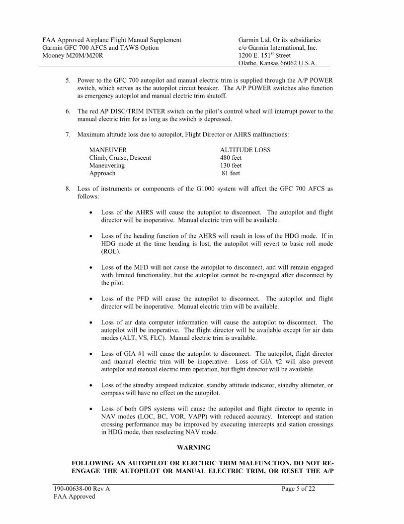
5. Power to the GFC 700 autopilot and manual electric trim is supplied through the A/P POWER switch, which serves as the autopilot circuit breaker. The A/P POWER switches also function as emergency autopilot and manual electric trim shutoff.
6. The red AP DISC/TRIM INTER switch on the pilot’s control wheel will interrupt power to the manual electric trim for as long as the switch is depressed.
7. Maximum altitude loss due to autopilot, Flight Director or AHRS malfunctions:
MANEUVER ALTITUDE LOSS Climb, Cruise, Descent 480 feet Maneuvering 130 feet Approach 81 feet
8. Loss of instruments or components of the G1000 system will affect the GFC 700 AFCS as follows:
Loss of the AHRS will cause the autopilot to disconnect. The autopilot and flight director will be inoperative. Manual electric trim will be available.
Loss of the heading function of the AHRS will result in loss of the HDG mode. If in HDG mode at the time heading is lost, the autopilot will revert to basic roll mode (ROL).
Loss of the MFD will not cause the autopilot to disconnect, and will remain engaged with limited functionality, but the autopilot cannot be re-engaged after disconnect by the pilot.
Loss of the PFD will cause the autopilot to disconnect. The autopilot and flight director will be inoperative. Manual electric trim will be available.
Loss of air data computer information will cause the autopilot to disconnect. The autopilot will be inoperative. The flight director will be available except for air data modes (ALT, VS, FLC). Manual electric trim is available.
Loss of GIA #1 will cause the autopilot to disconnect. The autopilot, flight director and manual electric trim will be inoperative. Loss of GIA #2 will also prevent autopilot and manual electric trim operation, but flight director will be available.
Loss of the standby airspeed indicator, standby attitude indicator, standby altimeter, or compass will have no effect on the autopilot.
Loss of both GPS systems will cause the autopilot and flight director to operate in NAV modes (LOC, BC, VOR, VAPP) with reduced accuracy. Intercept and station crossing performance may be improved by executing intercepts and station crossings in HDG mode, then reselecting NAV mode.
WARNING
FOLLOWING AN AUTOPILOT OR ELECTRIC TRIM MALFUNCTION, DO NOT RE-ENGAGE THE AUTOPILOT OR MANUAL ELECTRIC TRIM, OR RESET THE A/P

FAA Approved Airplane Flight Manual Supplement Garmin Ltd. Or its subsidiaries Garmin GFC 700 AFCS and TAWS Option Mooney M20M/M20R
c/o Garmin International, Inc. 1200 E. 151st Street Olathe, Kansas 66062 U.S.A.
190-00638-00 Rev A Page 6 of 22FAA Approved
POWER SWITCH, UNTIL THE CAUSE OF THE MALFUNCTION HAS BEEN DETERMINED AND CORRECTED.
10. If the optional TAWS function is installed in the G1000, the pilot will receive appropriate aural warnings and cautions for terrain and obstacles. The pilot should refer to the M20M/M20R Pilot’s Guide (Garmin doc. 190-00450-02, Revision A or later) for the terrain warning and caution messages and system information.

FAA Approved Airplane Flight Manual Supplement Garmin Ltd. Or its subsidiaries Garmin GFC 700 AFCS and TAWS Option Mooney M20M/M20R
c/o Garmin International, Inc. 1200 E. 151st Street Olathe, Kansas 66062 U.S.A.
190-00638-00 Rev A Page 7 of 22FAA Approved
SECTION II – LIMITATIONS
General Limitations:
1. The M20M/M20R Pilot’s Guide, P/N 190-00450-02 Revision A, or later revision must be immediately available to the flight crew. The software status stated in the Pilot’s Guide should match that displayed on the equipment..
2. The GFC 700 must utilize the following or later FAA approved software versions:
Sub-System Software VersionPFD 6.13MFD 6.13GMA 1347 2.11AHRS 2.03ADC 2.05GIA 4.70GPS 3.03GSA 2.10
The system software versions can be verified on the AUX group sub-page 6, “AUX - SYSTEM STATUS”.
3. The GFC 700 AFCS preflight test must be successfully completed prior to use of the autopilot, flight director or manual electric trim. Use of the autopilot or manual electric trim system is prohibited if the preflight test is not satisfactorily completed.
4. A pilot with the seat belt fastened must occupy the left pilot’s seat during all autopilot operations.
5. The autopilot must be off during takeoff and landing.
6. Autopilot maximum engagement speed – 180 KIAS Autopilot minimum engagement speed – 80 KIAS Electric Trim maximum operating speed – 195 KIAS
7. The autopilot must be disengaged below 200 feet AGL during approach operations and below 800 feet AGL during all other operations.
8. The GFC 700 autopilot is approved for Category 1 precision approaches and non-precision approaches only.
9. CDI mode sequencing (ILS CDI Capture) must be set to manual for instrument approaches conducted with the autopilot coupled.
10. Autopilot use is limited to the following weight and center of gravity envelope: 42.6” aft of datum at 2,900 lb and below, straight line variation to 44” aft of datum at 3,300 lb, straight line variation to 46” aft of datum at 3,368 lb, 51” aft of datum at all weights less than 3,368 lb.
11. Maximum fuel imbalance with autopilot engaged – 18 Gallons (108 lb).

FAA Approved Airplane Flight Manual Supplement Garmin Ltd. Or its subsidiaries Garmin GFC 700 AFCS and TAWS Option Mooney M20M/M20R
c/o Garmin International, Inc. 1200 E. 151st Street Olathe, Kansas 66062 U.S.A.
190-00638-00 Rev A Page 8 of 22FAA Approved
12. Navigation must not be predicated upon the use of TAWS.
NOTE: The terrain display is intended to serve as a situational awareness tool only. It may not provide either the accuracy or fidelity, or both, on which to solely base decisions and plan maneuvers to avoid terrain or obstacles.\
13. To avoid getting unwanted alerts, the TAWS must be inhibited when landing at an airport that is not included in the airport database.
14. Pilots are authorized to deviate from their current ATC clearance to the extent necessary to comply with TAWS warnings.
15. The TAWS databases have an area of coverage as detailed below:
a) The terrain database has an area of coverage from North 75 Latitude to South 60 Latitude in all longitudes.
b) The Airport Terrain Database has an area of coverage that includes the United States, Canada, Mexico, Latin America, and South America.
c) The Obstacle Database has an area of coverage that includes the United States.
NOTE: The area of coverage may be modified, as additional data sources become available.
16. TAWS must be inhibited prior to the Final Approach Fix (FAF) when conducting an instrument approach that terminates in a circling to land or side step maneuver.

FAA Approved Airplane Flight Manual Supplement Garmin Ltd. Or its subsidiaries Garmin GFC 700 AFCS and TAWS Option Mooney M20M/M20R
c/o Garmin International, Inc. 1200 E. 151st Street Olathe, Kansas 66062 U.S.A.
190-00638-00 Rev A Page 9 of 22
SECTION III – EMERGENCY PROCEDURES
Some emergency situations require immediate memorized corrective action. These numbered steps are printed in boxes within the emergency procedures and should be accomplished without the aid of the checklist.
AUTOPILOT OR ELECTRIC TRIM MALFUNCTION/FAILURE
NOTE
An autopilot or electric trim malfunction may be recognized by an unexpected deviation from the desired flight path, abnormal flight control or trim wheel movement, or flight director commands which cause unexpected or contradictory information on the other cockpit displays. It may be accompanied by the aural autopilot disconnect tone, a red AFCS or red AP indication on the PFD, or a yellow CHECK ATTITUDE on the PFD. The autopilot and AHRS monitors normally detect failures and automatically disconnect the autopilot.
Failure of the electric pitch trim, indicated by a red boxed PTRM annunciation on the PFD, may not cause the autopilot to disconnect. Be alert to possible autopilot out of trim conditions (see AUTOPILOT OUT OF TRIM procedure below), and expect residual control forces upon disconnect. The autopilot will not re-engage after disconnect with failed pitch trim. If any autopilot out of trim indication is present ( AIL, AIL, ELE, or ELE annunciations on PFD), expect substantial control wheel forces on autopilot disconnect.
1. A/P DISC/TRIM INTER Switch......................................DEPRESS AND HOLD while grasping control wheel firmly
2. Aircraft Attitude ........................MAINTAIN/REGAIN AIRCRAFT CONTROL, use standby attitude indicator if necessary
3. Pitch Trim ..........................................RETRIM if necessary, using the trim wheel 4. A/P POWER Switch ........................................................................................OFF 5. A/P DISC/TRIM INTER button ............................................................ RELEASE
WARNING
FOLLOWING AN AUTOPILOT, AUTOTRIM OR MANUAL ELECTRIC TRIM SYSTEM MALFUNCTION, DO NOT ENGAGE THE AUTOPILOT OR OPERATE THE MANUAL ELECTRIC TRIM UNTIL THE CAUSE OF THE MALFUNCTION HAS BEEN CORRECTED.
FAA Approved

FAA Approved Airplane Flight Manual Supplement Garmin Ltd. Or its subsidiaries Garmin GFC 700 AFCS and TAWS Option Mooney M20M/M20R
c/o Garmin International, Inc. 1200 E. 151st Street Olathe, Kansas 66062 U.S.A.
190-00638-00 Rev A Page 10 of 22
AUTOPILOT OUT OF TRIM (Yellow AIL, AIL, ELE, or ELE on PFD)
For ELE, or ELE Indication:
WARNING
DO NOT ATTEMPT TO OVERPOWER THE AUTOPILOT IN THE EVENT OF A PITCH MISTRIM. THE AUTOPILOT SERVOS WILL OPPOSE PILOT INPUT AND WILL CAUSE PITCH TRIM TO RUN OPPOSITE THE DIRECTION OF PILOT INPUT. THIS WILL LEAD TO A SIGNIFICANT OUT-OF-TRIM CONDITION RESULTING IN LARGE CONTROL WHEEL FORCE WHEN DISENGAGING THE AUTOPILOT.
CAUTION
Be prepared for significant sustained control forces in the direction of the annunciation arrow. For example, an arrow pointing down indicates nose down control wheel force will be required upon autopilot disconnect.
NOTE
Momentary illumination of the ELE or ELE indication during configuration or large airspeed changes is normal.
If the annunciation remains:
1. A/P DISC/TRIM INTER Switch ......................................DEPRESS AND HOLD while grasping control wheel firmly
2. Aircraft Attitude ........................MAINTAIN/REGAIN AIRCRAFT CONTROL, use standby attitude indicator if necessary
3. Pitch Trim.......................................... RETRIM if necessary, using the trim wheel 4. A/P POWER Switch ....................................................................................... OFF 5. A/P DISC/TRIM INTER button ............................................................RELEASE
WARNING
FOLLOWING AN AUTOPILOT, AUTOTRIM OR MANUAL ELECTRIC TRIM SYSTEM MALFUNCTION, DO NOT ENGAGE THE AUTOPILOT OR OPERATE THE MANUAL ELECTRIC TRIM UNTIL THE CAUSE OF THE MALFUNCTION HAS BEEN CORRECTED.
For AIL, AIL Indication:
1. Rudder Trim............................................................ VERIFY slip/skid indicator is centered
If annunciation remains: 2. Control Wheel .............................................................GRASP FIRMLY with both hands
FAA Approved

FAA Approved Airplane Flight Manual Supplement Garmin Ltd. Or its subsidiaries Garmin GFC 700 AFCS and TAWS Option Mooney M20M/M20R
c/o Garmin International, Inc. 1200 E. 151st Street Olathe, Kansas 66062 U.S.A.
190-00638-00 Rev A Page 11 of 22FAA Approved
CAUTION
Be prepared for sustained control forces in the direction of the annunciation arrow. For example, an arrow pointing to the right indicates that sustained right wing down control wheel force will be required upon autopilot disconnect.
3. A/P DISC/TRIM INTER button .................................................................DEPRESS 4. Autopilot ................................................................RE-ENGAGE if lateral trim re-established
AUTOPILOT DISCONNECT (Red AP flashing on PFD, continuous high-low aural tone)
1. A/P DISC/TRIM INTER Switch ............................... DEPRESS AND RELEASE (to cancel disconnect tone)
2. Pitch Trim ..........................................RETRIM if necessary, using the trim wheel
NOTE
The autopilot disconnect may be accompanied by a red boxed PTCH (pitch), ROLL, or AFCS on the PFD, indicating the axis which has failed, or that the automatic flight control system has failed. The autopilot cannot be re-engaged with any of these annunciations present.
AUTOPILOT OVERSPEED RECOVERY (Yellow MAXSPD on PFD)
1. Throttle.....................................................................................................REDUCE
When overspeed condition is corrected:
2. Autopilot ...................................... RESELECT VERTICAL MODE (if necessary)
NOTE
Overspeed recovery mode provides a pitch up command to decelerate the airplane at or below the maximum autopilot operating speed (180 KIAS). Overspeed recovery is not active in altitude hold (ALT) or glideslope (GS) modes.
FLASHING YELLOW MODE ANNUNCIATION
NOTE
Abnormal mode transitions (those not initiated by the pilot or by normal sequencing of the autopilot) will be annunciated by flashing the disengaged mode in yellow on the PFD. Upon loss of a selected mode, the system will revert to the default mode for the affected axis, either ROL or PIT. After 10 seconds, the new mode (PIT or ROL) will be annunciated in green.
Loss of selected vertical mode (FLC, VS, ALT, GS) 1. Autopilot mode controls ......................SELECT ANOTHER VERTICAL MODE

FAA Approved Airplane Flight Manual Supplement Garmin Ltd. Or its subsidiaries Garmin GFC 700 AFCS and TAWS Option Mooney M20M/M20R
c/o Garmin International, Inc. 1200 E. 151st Street Olathe, Kansas 66062 U.S.A.
190-00638-00 Rev A Page 12 of 22FAA Approved
If on an instrument approach: 2. Autopilot ..................................................DISCONNECT and continue manually,
or execute missed approach
Loss of selected lateral mode (HDG, VOR, GPS, LOC, VAPP, BC): 1. Autopilot mode controls........................SELECT ANOTHER LATERAL MODE If on an instrument approach: 2. Autopilot ..................................................DISCONNECT and continue manually,
or execute missed approach
LOSS OF NAVIGATION INFORMATION (Yellow VOR, VAPP, GPS or LOC flashing on PFD)
NOTE
If a navigation signal is lost while the autopilot is tracking it, the autopilot will roll the aircraft wings level and default to roll mode (ROL).
1. Autopilot ..........................................................SELECT HDG on mode controller 2. Nav Source .................................................... SELECT A VALID NAV SOURCE 3. Autopilot ..........................................................SELECT NAV on mode controller
If on an instrument approach at the time the navigation signal is lost:
4. Missed Approach Procedure ........................................EXECUTE (as applicable)
FAILURE OF THE PREFLIGHT TEST (Red boxed PFT on PFD)
1. A/P POWER Switch ............................................................................OFF
WARNING
DO NOT ATTEMPT TO ENGAGE THE AUTOPILOT OR OPERATE THE MANUAL ELECTRIC TRIM UNTIL THE CAUSE OF THE MALFUNCTION HAS BEEN CORRECTED.
NOTE
When the A/P POWER switch is OFF, the PFT FAIL annunciation will be removed and the autopilot and manual electric trim will be unavailable. Do not reset the switch unless the airplane is on the ground.

FAA Approved Airplane Flight Manual Supplement Garmin Ltd. Or its subsidiaries Garmin GFC 700 AFCS and TAWS Option Mooney M20M/M20R
c/o Garmin International, Inc. 1200 E. 151st Street Olathe, Kansas 66062 U.S.A.
190-00638-00 Rev A Page 13 of 22
“PULL UP” – RED TAWS WARNING
1. A/P DISC/TRIM INTER Switch.........................................................................................DEPRESS To disconnect the autopilot
2. Aircraft Attitude .................................................................. PULL BACK ON CONTROL WHEEL AND APPLY MAXIMUM POWER Climb at maximum angle
3. After Warning Ceases.................................................Reduce power, climb and maintain safe altitude
Only vertical maneuvers are recommended, unless either operating in visual meteorological conditions (VMC), or the pilot determines, based on all available information, that turning in addition to the escape maneuver is the safest course of action, or both.
TAWS CAUTION
When a TAWS CAUTION occurs, take positive corrective action until the alert ceases. Stop descending or initiate either a climb or a turn, or both, as necessary, based on analysis of all available instruments and information.
ABNORMAL TAWS ANNUNCIATIONS
1. If the white “TAWS N/A” status annunciator is displayed on the PFD, the system will no longer provide TAWS alerting or display relative terrain elevations. The crew must maintain compliance with procedures that ensure minimum terrain separation.
2. If the red “TAWS FAIL” status annunciator is displayed on the PFD, the system will no longer provide TAWS alerting or display relative terrain elevations. The crew must maintain compliance with procedures that ensure minimum terrain separation.
TAWS INHIBIT
The TAWS Forward Looking Terrain Avoidance (FLTA) and Premature Descent Alerts (PDA) functions may be inhibited to stop alerting for acceptable flight conditions. For detailed operating instructions regarding the G1000 TAWS Option, refer to the Garmin M20M/M20R Pilot’s Guide P/N 190-00450-02 Revision A, or later subsequent revision.
FAA Approved

FAA Approved Airplane Flight Manual Supplement Garmin Ltd. Or its subsidiaries Garmin GFC 700 AFCS and TAWS Option Mooney M20M/M20R
c/o Garmin International, Inc. 1200 E. 151st Street Olathe, Kansas 66062 U.S.A.
190-00638-00 Rev A Page 14 of 22FAA Approved
SECTION IV – NORMAL PROCEDURES
NOTE
Normal operating procedures for the GFC 700 are described in the Garmin G1000 Cockpit Reference Guide and the M20M/M20R Pilot’s Guide, P/N 190-00450-02 Revision A or later.
BEFORE STARTING ENGINE
NOTE
The AFCS system automatically conducts a preflight self-test upon initial power application. The preflight test is indicated by a white boxed PFT on the PFD. Upon successful completion of the preflight test, the PFT is removed, the red AFCS annunciation is removed, and the autopilot disconnect tone sounds.
l. MASTER Switch .......................................................................................... ON 2.A/P POWER Switch ..................................................................................... ON 3. Primary Flight Display (PFD) .............NO AUTOPILOT ANNUNCIATIONS 4. Autopilot Disconnect Tone ..................................................................... NOTE
AFTER TAKEOFF
WARNING
IT IS THE RESPONSIBILITY OF THE PILOT IN COMMAND TO MONITOR THE AUTOPILOT WHEN IT IS ENGAGED. THE PILOT SHOULD BE PREPARED TO IMMEDIATELY DISCONNECT THE AUTOPILOT AND TO TAKE PROMPT CORRECTIVE ACTION IN THE EVENT OF UNEXPECTED OR UNUSUAL AUTOPILOT BEHAVIOR.
DO NOT ATTEMPT TO MANUALLY FLY THE AIRPLANE WITH THE AUTOPILOT ENGAGED. THE AUTOPILOT SERVOS WILL OPPOSE PILOT INPUT AND WILL TRIM OPPOSITE THE DIRECTION OF PILOT INPUT (PITCH AXIS ONLY). THIS COULD LEAD TO A SIGNIFICANT OUT-OF-TRIM CONDITION. DISCONNECT THE AUTOPILOT IF MANUAL CONTROL IS DESIRED.
THE PILOT IN COMMAND MUST USE PROPER AUTOPILOT MODES AND PROPER ENGINE POWER SETTINGS TO ENSURE THAT AIRCRAFT SPEED IS MAINTAINED BETWEEN 80 KIAS AND 180 KIAS. IT WILL BE NECESSARY TO CHANGE ENGINE POWER TO MAINTAIN THE DESIRED RATE OF DESCENT WHEN OPERATING AT 180 KIAS.
OBSERVE THE MINIMUM AUTOPILOT OPERATING SPEED OF 80 KIAS. OPERATION IN PITCH (PIT) OR VERTICAL SPEED (VS) MODES BELOW THIS SPEED CAN RESULT IN AN AIRPLANE STALL. IF INDICATIONS OF AN AIRPLANE STALL ARE PRESENT, INCLUDING STALL WARNING HORN,
FAA Approved Airplane Flight Manual Supplement Garmin Ltd. Or its subsidiaries Garmin GFC 700 AFCS and TAWS Option Mooney M20M/M20R
c/o Garmin International, Inc. 1200 E. 151st Street Olathe, Kansas 66062 U.S.A.
190-00638-00 Rev A Page 15 of 22FAA Approved
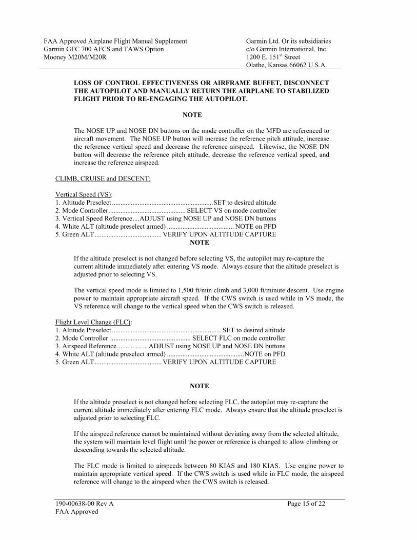
LOSS OF CONTROL EFFECTIVENESS OR AIRFRAME BUFFET, DISCONNECT THE AUTOPILOT AND MANUALLY RETURN THE AIRPLANE TO STABILIZED FLIGHT PRIOR TO RE-ENGAGING THE AUTOPILOT.
NOTE
The NOSE UP and NOSE DN buttons on the mode controller on the MFD are referenced to aircraft movement. The NOSE UP button will increase the reference pitch attitude, increase the reference vertical speed and decrease the reference airspeed. Likewise, the NOSE DN button will decrease the reference pitch attitude, decrease the reference vertical speed, and increase the reference airspeed.
CLIMB, CRUISE and DESCENT:
Vertical Speed (VS):1. Altitude Preselect ...........................................................SET to desired altitude 2. Mode Controller............................................. SELECT VS on mode controller 3. Vertical Speed Reference....ADJUST using NOSE UP and NOSE DN buttons 4. White ALT (altitude preselect armed) ....................................... NOTE on PFD 5. Green ALT....................................... VERIFY UPON ALTITUDE CAPTURE
NOTE
If the altitude preselect is not changed before selecting VS, the autopilot may re-capture the current altitude immediately after entering VS mode. Always ensure that the altitude preselect is adjusted prior to selecting VS.
The vertical speed mode is limited to 1,500 ft/min climb and 3,000 ft/minute descent. Use engine power to maintain appropriate aircraft speed. If the CWS switch is used while in VS mode, the VS reference will change to the vertical speed when the CWS switch is released.
Flight Level Change (FLC):1. Altitude Preselect ................................................................ SET to desired altitude 2. Mode Controller ............................................... SELECT FLC on mode controller 3. Airspeed Reference..................ADJUST using NOSE UP and NOSE DN buttons 4. White ALT (altitude preselect armed) .............................................NOTE on PFD 5. Green ALT....................................... VERIFY UPON ALTITUDE CAPTURE
NOTE
If the altitude preselect is not changed before selecting FLC, the autopilot may re-capture the current altitude immediately after entering FLC mode. Always ensure that the altitude preselect is adjusted prior to selecting FLC.
If the airspeed reference cannot be maintained without deviating away from the selected altitude, the system will maintain level flight until the power or reference is changed to allow climbing or descending towards the selected altitude.
The FLC mode is limited to airspeeds between 80 KIAS and 180 KIAS. Use engine power to maintain appropriate vertical speed. If the CWS switch is used while in FLC mode, the airspeed reference will change to the airspeed when the CWS switch is released.

FAA Approved Airplane Flight Manual Supplement Garmin Ltd. Or its subsidiaries Garmin GFC 700 AFCS and TAWS Option Mooney M20M/M20R
c/o Garmin International, Inc. 1200 E. 151st Street Olathe, Kansas 66062 U.S.A.
190-00638-00 Rev A Page 16 of 22FAA Approved
Altitude Hold (ALT):To capture a selected altitude: 1. Altimeter Setting .................................ADJUST TO APPROPRIATE VALUE 2. Altitude Preselect ........................................... SET TO DESIRED ALTITUDE 3. Vertical Mode and Reference............................... SELECT on mode controller 4. White ALT (altitude preselect armed)........................................ NOTE on PFD 5. Green ALT .......................................VERIFY UPON ALTITUDE CAPTURE
NOTE
In ALT mode, the autopilot will maintain the reference altitude shown in the autopilot window of the PFD regardless of the altitude in the altitude preselect window or the altimeter’s barometric pressure setting. If the altimeter setting is changed, the autopilot will climb or descend to maintain the reference altitude.
Altitude Hold (ALT):To maintain a desired altitude: 1. Altimeter Setting .................................ADJUST TO APPROPRIATE VALUE 2. Reaching desired altitude ............................ SELECT ALT on mode controller 3. Green ALT ............................................................................. VERIFY on PFD
Navigation Capture and Track:
1. Navigation Source............... SELECT VOR or GPS using CDI button on PFD 2. Course Bearing Pointer .............................SET using course knob (VOR only) 3. Intercept Heading ................ ESTABLISH in HDG or ROL mode (if required) 4. Mode Controller ......................................... SELECT NAV on mode controller 5. Green or White VOR or GPS annunciation ............................... NOTE on PFD 6. Vertical Mode and Reference............................... SELECT on mode controller
NOTE
If the Course Deviation Indicator (CDI) is greater than one dot from center, the autopilot will arm the NAV mode and indicate VOR or GPS in white on the PFD. The pilot must ensure that the current heading will result in a capture of the selected course. If the CDI is one dot or less from center, the autopilot will enter the capture mode when the NAV button is pressed and annunciate VOR or GPS in green on the PFD.

FAA Approved Airplane Flight Manual Supplement Garmin Ltd. Or its subsidiaries Garmin GFC 700 AFCS and TAWS Option Mooney M20M/M20R
c/o Garmin International, Inc. 1200 E. 151st Street Olathe, Kansas 66062 U.S.A.
190-00638-00 Rev A Page 17 of 22FAA Approved
APPROACH:
VOR
1. Navigation Source............................ SELECT VOR using CDI button on PFD 2. Course Bearing Pointer ................................................. SET using course knob 3. Intercept Heading.................ESTABLISH in HDG or ROL mode (if required) 4. Mode Controller...........................................SELECT APR on mode controller 5. Green or White VAPP annunciation.......................................... NOTE on PFD 6. Vertical Mode and Reference .............................. SELECT on mode controller 7. Airspeed .................... MAINTAIN 90 KIAS OR GREATER (Recommended)
NOTE
If the Course Deviation Indicator (CDI) is greater than one dot from center, the autopilot will arm the VAPP mode and indicate VAPP in white on the PFD. The pilot must ensure that the current heading will result in a capture of the selected course. If the CDI is one dot or less from center, the autopilot will enter the capture mode when the APR button is pressed and annunciate VAPP in green on the PFD.
ILS
1. Navigation Source.............................SELECT LOC using CDI button on PFD 2. Course Bearing Pointer ................................................. SET using course knob 3. Intercept Heading.................ESTABLISH in HDG or ROL mode (if required) 4. Mode Controller...........................................SELECT APR on mode controller 5. Green or White LOC and GS annunciations.............................. NOTE on PFD 6. Airspeed .................... MAINTAIN 90 KIAS OR GREATER (Recommended)
NOTE
Avoid continuous operation between 1760-1830 RPM while flying an ILS approach. If localizer or glideslope deviation indicator oscillations are observed, or, if airplane oscillations are felt or observed during an ILS approach, increase propeller speed above 1830 RPM. If increasing propeller speed does not stop the oscillations, execute a missed approach.
NOTE
When the selected navigation source is a valid ILS, glideslope coupling is automatically armed when tracking the localizer. The glideslope cannot be captured until the localizer is captured. The autopilot can capture the glideslope from above or below the glideslope.
GPS
1. Navigation Source............................. SELECT GPS using CDI button on PFD 2. Approach........................................................ LOAD in FMS and ACTIVATE 3. Intercept Heading.................ESTABLISH in HDG or ROL mode (if required) 4. Mode Controller...........................................SELECT APR on mode controller 5. Green or White GPS annunciation............................................. NOTE on PFD 6. Vertical Mode and Reference .............................. SELECT on mode controller 7. Airspeed .................... MAINTAIN 90 KIAS OR GREATER (Recommended)

FAA Approved Airplane Flight Manual Supplement Garmin Ltd. Or its subsidiaries Garmin GFC 700 AFCS and TAWS Option Mooney M20M/M20R
c/o Garmin International, Inc. 1200 E. 151st Street Olathe, Kansas 66062 U.S.A.
190-00638-00 Rev A Page 18 of 22FAA Approved
Back Course (BC)
1. Navigation Source............................ SELECT LOC using CDI button on PFD 2. Course Bearing Pointer ..................SET to ILS front course using course knob 3. Intercept Heading ................ ESTABLISH in HDG or ROL mode (if required) 4. Mode Controller ......................................... SELECT NAV on mode controller 5. Green or White BC annunciation ............................................... NOTE on PFD
NOTE
The course pointer must be at least 115 from the current magnetic heading before BC will be annunciated. Until that point, LOC will be annunciated.
Selecting NAV mode for back course approaches inhibits the glideslope from coupling.
6. Vertical Mode and Reference............................... SELECT on mode controller 7. Airspeed .................... MAINTAIN 90 KIAS OR GREATER (Recommended)
GO AROUND
1. Control Wheel ....................................................................... GRASP FIRMLY 2. GO AROUND button..................................... PUSH – Verify GA/GA on PFD
in lateral and vertical mode fields 3. Balked Landing ................................................................................EXECUTE 4. Missed Approach Procedure ....................................EXECUTE (as applicable) 5. Altitude Preselect ....................................................SET to appropriate altitude
At an appropriate safe altitude: 6. Autopilot Mode Controller.................SELECT appropriate lateral and vertical
modes on mode controller 7. Autopilot ..................................................................... RE-ENGAGE if desired
NOTE
If the missed approach procedure requires tracking the localizer outbound from the airport, use NAV mode to prevent inadvertent coupling to glideslope.

FAA Approved Airplane Flight Manual Supplement Garmin Ltd. Or its subsidiaries Garmin GFC 700 AFCS and TAWS Option Mooney M20M/M20R
c/o Garmin International, Inc. 1200 E. 151st Street Olathe, Kansas 66062 U.S.A.
190-00638-00 Rev A Page 19 of 22FAA Approved
SECTION V – PERFORMANCE
No change.

FAA Approved Airplane Flight Manual Supplement Garmin Ltd. Or its subsidiaries Garmin GFC 700 AFCS and TAWS Option Mooney M20M/M20R
c/o Garmin International, Inc. 1200 E. 151st Street Olathe, Kansas 66062 U.S.A.
190-00638-00 Rev A Page 20 of 22FAA Approved
SECTION VI – WEIGHT AND BALANCE
CENTER OF GRAVITY LIMITS
Autopilot use is limited to the following weight and center of gravity envelope
Aft Limit
51.0 inches aft of datum at 3,368 lbs and less
Forward Limits
46.0 inches aft of datum at 3,368 lbs
44.0 inches aft of datum at 3,300 lbs
42.6 inches aft of datum at 2,900 lbs and less

FAA Approved Airplane Flight Manual Supplement Garmin Ltd. Or its subsidiaries Garmin GFC 700 AFCS and TAWS Option Mooney M20M/M20R
c/o Garmin International, Inc. 1200 E. 151st Street Olathe, Kansas 66062 U.S.A.
190-00638-00 Rev A Page 21 of 22FAA Approved
SECTION VII – SYSTEM DESCRIPTIONS
The GFC 700 Automatic Flight Control system (AFCS), as installed in the Mooney M20M/M20R, consists of the following components:
One GDU which contains the following mode control buttons: AP (autopilot engage/disengage); FD (Flight Director On/Off); HDG (Heading mode On/Off); NAV (Nav mode On/Off); APR (Approach mode On/Off); ALT (Altitude Hold mode On/Off); VS (Vertical Speed mode On/Off); FLC (Flight Level Change mode On/Off); NOSE UP and NOSE DN (vertical mode reference change). This GDU is installed as the MFD. Servos with autopilot processing logic in the pitch, roll and pitch trim control systems Servo mounts and brackets Flight Director processing logic in the GIAs Control wheel-mounted elevator trim switch (split switch) Control wheel-mounted trim interrupt and autopilot disconnect switch Control wheel-mounted CWS (Control Wheel Steering) switch Remote-mounted go-around switch (on the instrument panel, forward of the throttle) PFD/MFD mounted altitude preselect knob (ALT) PFD/MFD mounted heading select knob (HDG)
Flight Director commands and autopilot modes are displayed on the PFD. Full AFCS functionality is only available with the both displays operating, and will disconnect under certain reversionary conditions.
Upon initial system power-up, the system undergoes a preflight test. At the end of the test, the autopilot disconnect tone sounds and the PFT and AFCS annunciations are removed. Successful completion of the preflight test is required for the autopilot and manual electric trim to function.
Annunciation of the flight director and autopilot modes is shown in the lower status field of the PFD. In general, green indicates active modes and white indicates armed modes. When a mode is directly selected by the pilot, no flashing of the mode will occur. When automatic mode changes occur, the new mode will be annunciated with a flashing annunciation for ten seconds in green. If an active mode becomes unavailable for some reason, the mode will flash for ten seconds in yellow and be replaced by the default mode in green.
Normal autopilot disconnects are annunciated with a yellow flashing AP on the PFD accompanied by a high-low autopilot disconnect tone. The yellow flashing AP and disconnect tone will cancel automatically after 5 and 2 seconds respectively, or may be manually cancelled by pressing the A/P DISC/TRIM INTER switch, or the manual electric trim (MET) switch. Normal disconnects are those initiated by the pilot with the A/P DISC/TRIM INTER switch, the MET switch, the AP button on the MFD mode controller, or the GO AROUND button. Abnormal disconnects will be accompanied by a continuous red flashing AP on the PFD accompanied by a continuous autopilot disconnect tone. The disconnect tone and flashing alert may be cancelled by pressing the A/P DISC/TRIM INTER switch or the MET switch.
Refer to the Garmin M20M/M20R Pilot’s Guide P/N 190-00450-02 Revision A, or later subsequent revision for a complete description of the GFC 700 system and operating procedures.

FAA Approved Airplane Flight Manual Supplement Garmin Ltd. Or its subsidiaries Garmin GFC 700 AFCS and TAWS Option Mooney M20M/M20R
c/o Garmin International, Inc. 1200 E. 151st Street Olathe, Kansas 66062 U.S.A.
190-00638-00 Rev A Page 22 of 22FAA Approved
SECTION VIII – HANDLING AND SERVICE
No change.