Embed Size (px)
Citation preview

NATIONAL CODE OF PRACTICE for
LIGHT VEHICLE CONSTRUCTION and
MODIFICATION
SECTION LS TYRES, RIMS, SUSPENSION
AND STEERING
VERSION 2.1 NOVEMBER 2015

Section LS Tyres, Rims, Suspension and Steering
Version 2.1 – 1 November 2015 Page 2/LS80
Vehicle Standards Bulletin 14
National Code of Practice for Light Vehicle Construction and Modification (VSB 14)
Important Information for Users
Users of VSB 14 need to be aware that this document needs to be used in conjunction with the appropriate administrative requirements of the jurisdiction in which they wish to either register a vehicle or to obtain approval for a modification for an already registered vehicle. Administrative requirements include, amongst other things, processes for vehicle registration, obtaining exemptions, obtaining modification approvals, vehicle inspections, preparation and submission of reports and the payment of appropriate fees and charges.
If unsure of any of the requirements specified in VSB 14, or if more information is needed for any other issues concerning the administrative requirements, users should contact their relevant Registration Authority prior to commencing any work.
While VSB 14 provides advice on the construction of Individually Constructed Vehicles (ICVs) and the execution of modifications, it is not to be taken to be a design manual. Determination of component strength, performance, suitability and functionality must be either calculated or determined on a case by case basis by suitably qualified personnel experienced in each matter under consideration.
Users of VSB 14 also need to ensure that they refer to the most recent version of the relevant Section/s when working on a project. The version is identified by the version number and date on the face page of each Section. The version and date is also located in the footer of each page in each Section. On the website the version number is specified in the Section file name for easy identification.
If a project is taking a long time to complete, check the currency of the version you are using.
Users must be familiar with the provisions stated in the Preface and Introduction. These two Sections provide the necessary background information to assist users in understanding how VSB 14 is administered by Registration Authorities across Australia, on how it is structured, and the meaning of the types of modification codes specified in VSB 14. If not already done so, users should download them for study and reference.
Understanding these requirements is important to ensure that the correct processes are followed thereby reducing the likelihood of having work rejected by Registration Authorities.
Many of the Sections refer to other Sections within VSB 14 for further information or additional requirements. Users must read and apply all relevant Sections.
If in doubt about any issue concerning or contained in VSB 14, users should seek clarification from the appropriate state or territory Registration Authority.
Please do not contact Vehicle Safety Standards (VSS) of the Australian Government Department of Infrastructure and Transport in Canberra about VSB 14. VSS provides the website as a service only.

Section LS Tyres, Rims, Suspension and Steering
Version 2.1 – 1 November 2015 Page 3/LS80
CONTENTS
1 Scope
6
1.1 Basic Modifications Not Requiring Certification 6
1.2 Modifications Requiring Certification under Section LS 6
1.3 Modifications Not Covered Under Section LS 6
2
General Requirements 7
2.1 Driveability 7
2.2 Strength and Flexibility 9
2.3 Fabrication 9
2.4 Suspension and Steering Terminology 11
2.5 Relevant Publications 14
2.6 Modifications to Vehicles Equipped with ESC 15
2.7 Safety Issues Associated with Raising or Lowering a Vehicle 15
3 Australian Design Rules 17
4 Basic Modifications Without Certification 18
4.1 Replacement Tyres on Standard (or Manufacturer’s Optional) Rims 18
4.2 Non-standard Tyres and Rims 19
4.3 Replacement Tyres and Rims on Vehicles with Modified Axles, Suspension and/or Steering 23
4.4 Shock Absorbers 23
4.5 Sway Bars 24
4.6 Track Rods 24
4.7 Strut Braces 24
4.8 Power Steering 24
4.9 Steering Wheels 24
4.10 Rose or Heim Joints 25
4.11 Lowering or Raising Vehicles 26
5 Certified Modifications (LS Codes) 28
LS1 LHD Vehicle Steering Conversion (Design) 29
Checklist 31

Section LS Tyres, Rims, Suspension and Steering
Version 2.1 – 1 November 2015 Page 4/LS80
LS2 LHD Vehicle Steering Conversion 36
Checklist 37
LS3 Front Suspension and Steering Modification (Design) 41
Checklist 51
LS4 Front Suspension and Steering Modification 58
Checklist 59
LS5 Rear Suspension Modification (Design) 62
Checklist 65
LS6 Rear Suspension Modification 67
Checklist 68
LS7 High Lift - 50mm to 150mm (Design) 70
Checklist 74
LS8 High Lift - 50mm to 150mm Modification 77
Checklist 78

Section LS Tyres, Rims, Suspension and Steering
Version 2.1 – 1 November 2015 Page 5/LS80
Document Amendments by Version
Version Amendments Version 2 Published 1 January 2011
Clause 2.6 added advising that modifications to vehicles equipped with ESC have certain requirements.
Reference to commercial vehicles replaced with goods vehicle.
The allowable wheel track increase of all off-road four wheel drive vehicles and goods vehicles (ADR category MC, NA, NB) has now been increased to no more than 50mm beyond the maximum specified by the vehicle manufacturer for the particular model.
Codes LS7 and LS8 have been updated with more information added to content and checklists – amount of vehicle lift covered has not been changed from the original version of the VSB 14.
The following note has been added to codes LS7 and LS8.
Designers and modifiers in NSW need to check with their Registration Authority as to the provisions which exist in NSW for Code LS7 and LS8 as they may be different to those expressed in this code of practice.
This document has also a number of editorial amendments that have had no affect on its technical content.
Version Amendments Version 2.1 Published 1 November 2015
The Note in Section 1.1 and 4.11 related to NSW notification requirements has been removed.
Clause 2.6 advising that modifications to vehicles equipped with ESC have certain requirements has been amended for basic modifications on suspension alterations.

Section LS Tyres, Rims, Suspension and Steering
Version 2.1 – 1 November 2015 Page 6/LS80
1 SCOPE This Section outlines the minimum design, installation and fabrication requirements for the following light vehicle modifications involving tyres, rims, suspension and steering.
1.1 BASIC MODIFICATIONS NOT REQUIRING CERTIFICATION The following modifications may be performed without certification if they are carried out in accordance with sub-section 2 General Requirements and the total change in vehicle height resulting from all modifications performed, does not exceed 50mm.
Tyre and rim substitution carried out within the limits specified in this Section;
Lowering and raising suspensions (by not more than one third of the original suspension travel provided the original vehicle height is not increased or decreased by more than 50mm);
Raising the vehicle with a body lift kit provided the original vehicle height is not increased by more than 50mm (refer to sub-section 4.11 for conditions and limitations);
Shock absorber substitution;
Spring and sway bar substitution;
Track rod and strut brace installation;
Steering wheel substitution (refer to sub-section 4.9 of this Section); and
Power steering (manufacturer’s option) conversion.
1.2 MODIFICATIONS REQUIRING CERTIFICATION UNDER SECTION LS The following modifications require certification under the LS Codes;
Left to right hand drive steering conversions;
Steering and suspension modifications;
Power steering (non-standard) conversion;
Rack and pinion steering conversion;
Suspension strut or upright substitution;
Rear axle substitution; and
Raising the vehicle beyond 50mm but not more than 150mm.
1.3 MODIFICATIONS NOT COVERED UNDER SECTION LS The following modifications are not covered under Section LS, nor by any other Section of VSB 14.

Section LS Tyres, Rims, Suspension and Steering
Version 2.1 – 1 November 2015 Page 7/LS80
Vehicle lifts that exceed 150mm: Raising vehicles beyond 150mm is not covered under this Code of Practice.
Vehicle Lifts to any Vehicle that has had its track reduced: Vehicles that have had a track reduction will need to be assessed on a case-by-case basis.
Remote Steering Systems: Steering systems that operate without complete mechanical connection (such as hydraulic or electric actuation) are not covered in this Code of Practice.
Steering Wheels Fitted with Integral Airbags: VSB 14 does not cover steering wheels fitted with air bags.
Installation of Variable Air or Hydraulic Suspension Systems: Installation of non-original suspension systems that allow the ride-height of the vehicle to be varied by the driver are not covered under this Code of Practice.
Modifications to Vehicles fitted with Electronic Stability Control (ESC): These vehicles have limitations on the modifications covered by Section LS – refer to Clause 2.6 for further details.
2 GENERAL REQUIREMENTS This sub-section applies to all light vehicles and must be read and applied in conjunction with all the LS Codes applicable to the proposed modifications.
Modified vehicles must continue to comply with the Australian Design Rules (ADRs) to which they were originally constructed, except as allowed for in the Australian Vehicle Standards Rules (AVSR). These modified vehicles must also comply with the applicable in-service requirements of the AVSR.
Modified pre-ADR vehicles must continue to comply with the AVSR.
Compliance with the AVSR also means compliance with the equivalent regulations of a State or Territory of Australia.
The use of the word wheel means the tyre and rim combination.
2.1 DRIVEABILITY Driveability in this context means that when driven on the road the vehicle responds to the drivers inputs without any dangerous or undesirable reactions and meets the turning and clearance requirements of the AVSR.
Owners wishing to alter the appearance and/or road handling characteristics of their vehicles often alter suspensions and fit tyres and rims different from the original manufacturer’s specifications. Some changes can achieve improvements in cornering stability, but other changes, including unsuitable tyre and rim selection can lead to dangerous situations. The following should be considered:
2.1.1 Steering Behaviour Fitting wider rims and tyres usually involves altering the steering scrub radius. This can result in unpredictable steering response characteristics.
Tyres contacting body and suspension components can reduce the vehicle’s turning circle.

Section LS Tyres, Rims, Suspension and Steering
Version 2.1 – 1 November 2015 Page 8/LS80
2.1.2 Roadholding and Handling
The roadholding and handling qualities of a modified vehicle must not be adversely affected.
2.1.3 Braking Behaviour
Some non-standard rims and tyres fitted to cars with diagonally split braking systems can cause reduced directional stability in the event of brake failure. Larger diameter tyres also require greater pedal pressure to achieve the same braking distances.
2.1.4 Ground Clearance and Running Clearance
Ground clearance, of a vehicle, means the minimum distance to the ground from a point on the underside of the vehicle, except a point on a tyre, wheel, wheel hub, brake backing plate or flexible mudguard or mudflap of the vehicle.
Running clearance, of a vehicle, means the distance from the surface on which an unladen vehicle is standing to the lowest point on the vehicle excluding unsprung mass.
Vehicles built to comply with the Third Edition ADRs must comply with the ground clearance requirements of ADR 43/…. Vehicles built to comply with ADR 43/04 must also comply with the running clearance requirements.
All other motor vehicles with more than 3 wheels must have a ground clearance of:
at least 100mm at any point within 1 metre of an axle; and
at least one-thirtieth of the distance between the centres of adjacent axles at the midpoint between them (refer Figure LS1); and
at any other point — at least the distance that allows the vehicle to pass over a peak in the road with a gradient on either side of 1:15, if the wheels of 1 axle of the vehicle are on the slope on one side of the peak and the wheels of the next axle are on the slope on the other side.
Figure LS1 Measuring Ground Clearance
2.1.5 Turning Circle
The vehicle must have a sufficient turning circle in each direction and must meet all ADR dimensional requirements.
2.1.6 Tyre Deflation
Any modifications to suspension and steering, including replacement tyres and rims, must ensure that the vehicle’s body, exhaust system, axles, suspension or steering components do not contact the road when tyre(s) deflate. Therefore, if one or more tyres deflate when the vehicle is on a level road, the rims and tyres must be the only part of the vehicle in contact with the road.

Section LS Tyres, Rims, Suspension and Steering
Version 2.1 – 1 November 2015 Page 9/LS80
2.1.7 Ride Height
Ride height is a very important parameter as it has a direct influence on a vehicle’s centre of mass (centre of gravity) and hence its stability and performance.
2.1.8 Suspension Travel
It is important to retain at least two thirds of the original suspension travel in either direction in order to maintain safe road holding characteristics.
2.2 STRENGTH AND FLEXIBILITY When replacing wheels and tyres, and modifying suspension and steering components, consideration should be given to the following:
2.2.1 Strength of Suspension and Steering Components
Changes in wheel width and offset, and bump clearance can cause significant increases in stress levels in suspension and steering components of both independent and beam axle suspensions.
2.2.2 Fatigue Strength
Some modifications that are satisfactory in the short term (e.g. on competition cars that travel relatively short distances) are often completely unsuitable for road use because of the effects of metal fatigue. A suspension component on a road car can break from metal fatigue at stresses much less than that experienced during competition use.
2.2.3 Flexible Arms and Joints
Some suspension components (flexible arms and joints) are designed to twist when the suspension moves vertically. Boxing-in these components and/or using stiffer replacement bushes can cause large stresses in mounting bolts and brackets causing them to break or tear out. It is recommended that replacement of rubber flexing bushes with harder bushes should only be done in applications where single plane movement occurs.
2.3 FABRICATION All work must be performed in accordance with recognised engineering standards. Cutting, heating, welding or bending of components should be avoided by choosing unmodified production components wherever possible.
2.3.1 Welding, Fasteners and Electroplating
Mandatory requirements and guidance on the above items are contained in Section LZ Appendices.
For the use of fasteners refer to Appendix A Fasteners;
For welding techniques and procedures refer to Appendix C Heating and Welding of Steering Components; and
For electroplating refer to Appendix D Electroplating.
2.3.2 Mating Parts
Standard features such as splines, tapers and keyways must conform to published standards and their mating parts must conform to matching standards.

Section LS Tyres, Rims, Suspension and Steering
Version 2.1 – 1 November 2015 Page 10/LS80
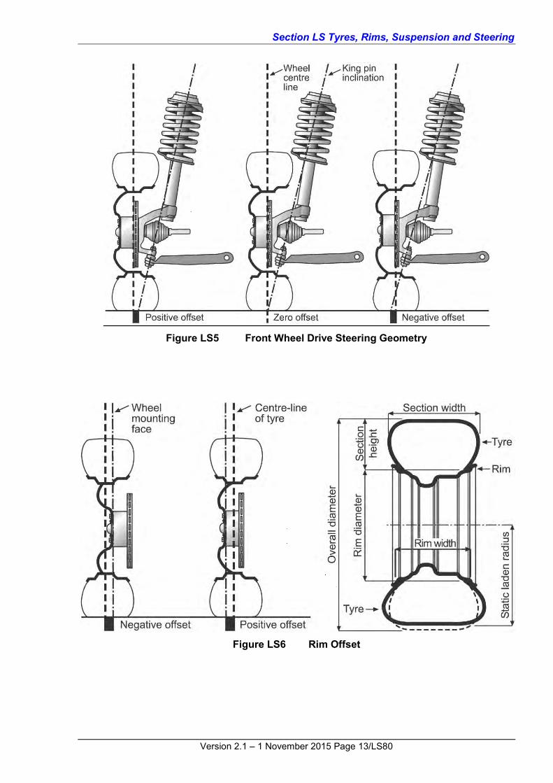
2.4 SUSPENSION AND STEERING TERMINOLOGY Figures LS2, LS3, LS4, LS5 and LS6 diagrammatically illustrate the common terminology used in suspension and steering systems.
Figure LS2 Typical Steering and Suspension Systems

Section LS Tyres, Rims, Suspension and Steering
Version 2.1 – 1 November 2015 Page 11/LS80
Figure LS3 Typical Steering and Suspension Systems

Section LS Tyres, Rims, Suspension and Steering
Version 2.1 – 1 November 2015 Page 12/LS80
Figure LS4 Rear Suspension Systems
Section LS Tyres, Rims, Suspension and Steering
Version 2.1 – 1 November 2015 Page 13/LS80
Figure LS5 Front Wheel Drive Steering Geometry
Figure LS6 Rim Offset

Section LS Tyres, Rims, Suspension and Steering
Version 2.1 – 1 November 2015 Page 14/LS80
2.5 RELEVANT PUBLICATIONS The following publications provide background information relating to the types of modifications covered in this Section:
Automotive Suspensions – Campbell, Colin – ISBN 412-16420-5;
Vehicle System Components Design and Safety – Limpert, Rudolf - ISBN 0-471-08133-7;
Automotive Suspensions Steering Alignment and Brakes – Billiet, Walter and Alley, Walter – ISBN 0-8269-0122-2; and
Theory and Practice of Chassis Tuning – Norbye, Jan – ISBN 0-85113-076-3.
2.6 MODIFICATIONS TO VEHICLES EQUIPPED WITH ESC Many modern vehicles are now being equipped with a safety feature known as Electronic Stability Control (ESC). (ESC is also known by other terms including Vehicle Stability Control or Dynamic Stability Control).
ESC provides motorists additional safety in terms of vehicle stability and handling, particularly in difficult situations where loss of control could otherwise occur. ESC uses computer technology to assist the driver in maintaining control in emergency situations – particularly when executing avoidance manoeuvres involving sudden swerving and in cases when the vehicle begins to slide and rotate sideways.
Braking is automatically applied to individual wheels, such as the outer front wheel to counter oversteer, or the inner rear wheel to counter understeer. Some ESC systems also reduce engine power until steering control is regained.
ESC is programmed by the vehicle manufacturer for the vehicle to which it is fitted taking into account a number of design parameters such as brake, engine and transmission performance, tyre specifications, steering systems, suspension (type and performance characteristics), mass of the vehicle and weight distribution.
To remain within the scope of VSB14, a vehicle fitted with ESC and modified with a suspension lift up to 50mm beyond the original manufacturer’s standard height can be carried out under the basic modification without certification guidelines as listed in Section 4.
Vehicle modifications with a suspension lift above 50mm or due to a combination of any other lift (tyres, or body blocks) are required to meet this guideline and Code LS7 or Code LS8 where applicable.
In the case of non-off road passenger vehicles fitted with ESC that are lowered beyond the original manufacturer’s standard, this allowance only applies where the reduction in ride height is no lower than regulated ground clearance and other suspension requirements. Additional information on suspension requirements are contained in;
Section 2.7 Safety Issues Associated with Raising or Lowering a Vehicle; and
Section 4 – Basic Modifications without Certification.

Section LS Tyres, Rims, Suspension and Steering
Version 2.1 – 1 November 2015 Page 15/LS80
2.7 SAFETY ISSUES ASSOCIATED WITH RAISING OR LOWERING A VEHICLE Modifying a vehicle’s suspension by raising or lowering it has the potential to decrease its safety by compromising its handling and braking performance, affecting safety features, and by altering the position of impact-absorbing sections.
The safety of raised or lowered vehicles may be reduced in the following areas:
Dynamic stability – Raising a vehicle correspondingly raises its centre of gravity, which increases its propensity to overturn;
Road handling capabilities – In addition to the above, raising a vehicle’s centre of gravity adversely affects its ability to manoeuvre, such as changing lanes and cornering;
Electronic stability control (ESC) – ESC is an important safety feature that helps a driver retain control of a vehicle under extreme driving circumstances, such as those experienced during emergency avoidance manoeuvres. ESC is specifically programmed by the manufacturer for a vehicle’s particular configuration. Altering the ride height could affect this programming and detrimentally affect the benefits of ESC;
Braking characteristics* - Altering a vehicle’s ride height by changing the tyres or rims can affect the braking system performance. Larger diameter tyres require the driver to apply greater pedal pressure to stop the vehicle in the same distance as would be required with the original tyres fitted. Also increases in the height of the centre of gravity of the vehicle can affect how a vehicle responds to severe braking;
Ground clearance* - Lowering a vehicle decreases its ground clearance, which could cause the under chassis to impact the ground when travelling on uneven or rough surfaces, or simply when driving over standard road features such as speed humps, culverts or kerbs;
Occupant protection* - The design of a vehicle incorporates minimum specified levels of occupant protection that help safeguard persons travelling in the vehicle in the event of it crashing. This is usually achieved by the front and rear bumpers, crumple zones and by providing locally strengthened sections in the vehicle’s structure. These are positioned at designated heights above the ground specifically to absorb the impact from another vehicle. Altering a vehicle’s height correspondingly alters the position of these safety features, which may reduce the levels of protection the vehicle affords its occupants;
Risks to occupants of other vehicles – In addition to the above, altering the position of a vehicle’s bumpers means its point of contact with other vehicles may be above or below their bumpers, crumple zones and locally strengthened sections, thereby exposing their occupants to an increased risk of injury in the event of them crashing with a raised or lowered vehicle;
Risks to vulnerable road users – Altering the position of a vehicle’s bumpers changes its point of contact with vulnerable road users, such as pedestrians and cyclists, with a corresponding increase of greater risk or injury to them in the event of their being struck by a modified vehicle even at slow speeds. This risk is compounded if the vehicle has bull-bars fitted;
Driver’s field of vision – Altering a vehicle’s ride height changes the driver’s view of the road. When a vehicle is raised, the distance to the point the driver can see the ground in front of them is increased. This results in an increased blind zone immediately in front of the driver where they cannot readily see other road users, such as pedestrians, cyclists and smaller vehicles. Similarly, blind zones along the passenger side and rear of the vehicle may also be significantly increased;

Section LS Tyres, Rims, Suspension and Steering
Version 2.1 – 1 November 2015 Page 16/LS80
Unexpected vehicle behaviour – A vehicle’s suspension system involves complex relationships between its components. Modifications to some components can introduce unexpected consequences in the vehicle, such as introducing body roll induced wheel or axle steer and wheel angle while turning, all of which could significantly degrade the handling characteristics of the vehicle;
Impact on other components – Modifications to ride height can stress or expose other components, such as brake hoses or ABS/ESC sensor wires, resulting in their premature failure;
Trajectory of headlights* - Altering a vehicle’s height alters the trajectory of its headlights, which could cause them to dazzle other road users either by shining directly in their eyes or by reflecting in rear vision mirrors; and
Exposing dangerous parts – Raising a vehicle by fitting tyres with a greater diameter can reduce the protection afforded by the mudguards and bodywork.
* There are specific ADRs applicable to these items.

Section LS Tyres, Rims, Suspension and Steering
Version 2.1 – 1 November 2015 Page 17/LS80
3 AUSTRALIAN DESIGN RULES A modified vehicle must continue to comply with the ADRs to which it was originally constructed, except as allowed for in the AVSR.
Outlined in Table LS1 below are requirements and/or components of the vehicle that may be affected by the modifications and that may require re-certification, testing and/or data to show continuing compliance for the modified vehicle. This is not an exhaustive list and other modifications may also affect ADR compliance.
Table LS1 Summary of items that if modified, may detrimentally affect compliance with applicable ADRs
ADR Title and Comments
7, 7/… Brake Hoses
10x, 10/… Steering Column
12, 12/… Glare Reduction in Field of View
13/… Installation of Lighting and Light Signalling Devices on other than L-group Vehicles
15, 15/… Demisting of Windscreen
18x, 18/… Instrumentation
20, 20/… Safety Rims
21, 21/… Instrument Panel (RHD, LHD steering conversion)
23x, 23/… Passenger car tyres 24x, 24/… Tyre and Rim Selection (tyre placard, speed rating, These
requirements are now specified in ADR 42/ for vehicles manufactured after 1 January 2005)
31, 31/…, 35x, 35/…
Braking
42/… General Safety Requirements
43/… Vehicle Configuration and Dimensions (ground clearance)
The applicable ADRs are individually listed on the Identification Plate of Second Edition ADR vehicles. For Third Edition ADR vehicles, the Identification Plates contain the vehicle category and the date of manufacture, from which the applicable ADRs can be determined (refer to the applicability tables in Section LO ADR Compliance).
Alternatively, ADR applicability tables for individual vehicle categories may be referenced on the Department of Infrastructure and Transport RVCS website at the following address and under the section titled ADR Applicability Tables:
http://rvcs.dotars.gov.au/
Section LS Tyres, Rims, Suspension and Steering
Version 2.1 – 1 November 2015 Page 18/LS80
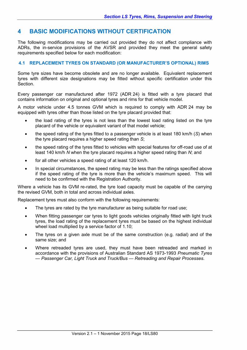
4 BASIC MODIFICATIONS WITHOUT CERTIFICATION
The following modifications may be carried out provided they do not affect compliance with ADRs, the in-service provisions of the AVSR and provided they meet the general safety requirements specified below for each modification:
4.1 REPLACEMENT TYRES ON STANDARD (OR MANUFACTURER’S OPTIONAL) RIMS
Some tyre sizes have become obsolete and are no longer available. Equivalent replacement tyres with different size designations may be fitted without specific certification under this Section.
Every passenger car manufactured after 1972 (ADR 24) is fitted with a tyre placard that contains information on original and optional tyres and rims for that vehicle model.
A motor vehicle under 4.5 tonnes GVM which is required to comply with ADR 24 may be equipped with tyres other than those listed on the tyre placard provided that:
the load rating of the tyres is not less than the lowest load rating listed on the tyre placard of the vehicle or equivalent variant of that model vehicle;
the speed rating of the tyres fitted to a passenger vehicle is at least 180 km/h (S) when the tyre placard requires a higher speed rating than S;
the speed rating of the tyres fitted to vehicles with special features for off-road use of at least 140 km/h N when the tyre placard requires a higher speed rating than N; and
for all other vehicles a speed rating of at least 120 km/h.
In special circumstances, the speed rating may be less than the ratings specified above if the speed rating of the tyre is more than the vehicle’s maximum speed. This will need to be confirmed with the Registration Authority.
Where a vehicle has its GVM re-rated, the tyre load capacity must be capable of the carrying the revised GVM, both in total and across individual axles.
Replacement tyres must also conform with the following requirements:
The tyres are rated by the tyre manufacturer as being suitable for road use;
When fitting passenger car tyres to light goods vehicles originally fitted with light truck tyres, the load rating of the replacement tyres must be based on the highest individual wheel load multiplied by a service factor of 1.10;
The tyres on a given axle must be of the same construction (e.g. radial) and of the same size; and
Where retreaded tyres are used, they must have been retreaded and marked in accordance with the provisions of Australian Standard AS 1973-1993 Pneumatic Tyres — Passenger Car, Light Truck and Truck/Bus — Retreading and Repair Processes.

Section LS Tyres, Rims, Suspension and Steering
Version 2.1 – 1 November 2015 Page 19/LS80
4.2 NON-STANDARD TYRES AND RIMS
When wheels that do not comply with the vehicle manufacturer’s specifications are fitted to a vehicle with standard axles and suspension, the following requirements must be met:
4.2.1 Tyre and Rim Construction
The combination of tyre and rim must meet size and construction requirements of ADR 23, or if the vehicle was manufactured before 1 January 1974, one of the following standards:
Tyre and Rim Standards Manual of the Tyre and Rim Association of Australia;
1981 Tire and Rim Association Inc. Year Book;
British Standard BS AU50;
Japan Automobile Tire Manufacturers Association Year Book; and
Japanese Industrial Standards (JIS-D4202).
Replacement aluminium alloy rims must comply with one of the following standards:
Wheel Industries Association (Australia) (WIA);
Standards Association of Australia (SAA);
Technischer Überwachungsverein (TÜV); and
Japanese Industrial Standards (JIS).
Rims must not have a full circumferential weld, other than one that attaches the rim to the wheel centre.
4.2.2 Wheel Attachment
Replacement wheels must be designed for the particular hub/axle and have the same bolt/stud pitch circle diameter and the same centre location method. The wheel nuts or bolts must have the same tapers as the wheel. Wheels with slotted bolt/stud holes must not be used.
Replacement aluminium alloy rims must be located on the hub/axle by the same diameter centre spigot as the original wheel, using suitable adaptor rings where necessary.
Wheel nuts and bolts must have a thread engagement length at least equal to the thread diameter, except where specified otherwise by the vehicle manufacturer.
Wheel spacers (or adaptors for dual wheel conversions) between the wheel mounting face and the road wheel must not be used unless fitted as original equipment by the vehicle manufacturer.
Modifications to disc brake callipers, hubs and suspension and steering components to enable the fitting of replacement wheels must not be undertaken.
4.2.3 Clearance
No part of the wheel must touch any part of the body, chassis, steering, braking system or suspension under any operating condition. To check this, the vehicle must be fully laden and capable of negotiating raised obstacles that would normally be encountered whilst driving such as speed humps and driveway entries. This test should be conducted from lock to lock without any part of the rim or tyre contacting any other part of the vehicle. Test weight for passengers is 68kg plus 15kg per person for luggage where luggage space is provided.
The wheels must be contained within the bodywork, or mudguards (including flares) when the wheels are in the straight ahead position.
Steering and/or suspension stops must not be modified to provide clearance for wheels.

Section LS Tyres, Rims, Suspension and Steering
Version 2.1 – 1 November 2015 Page 20/LS80
4.2.4 Overall Nominal Diameter
The overall diameter of any tyre fitted to a passenger car or passenger car derivative must not be more than 15mm larger or 26mm smaller than that of any tyre designated by the vehicle manufacturer for that model.
The overall diameter of any tyre fitted to:
4WD passenger vehicles specifically designed for off-road use (typically MC ADR category). All wheel drive (AWD) vehicles including those AWD vehicles that may be certified as MC ADR category, (also commonly known as soft roaders) are not included in this category;
4WD goods vehicles and their 2WD equivalents if the chassis and running gear are essentially the same as the 4WD version (N ADR category); or
any medium weight goods vehicle (NA2, NB ADR category).
Must not be more than 50mm larger or 26mm smaller than that of any tyre designated by the vehicle manufacturer for that vehicle.
Note: Increases in tyre diameter are subject to compliance with all other requirements specified under this clause (Clause 4.2 Non-Standard Tyres and Rims) and may therefore be limited by other factors such as insufficient clearance.
Speedometer accuracy must be maintained for the selected tyre and rim combination to within the degree of accuracy specified in ADR 18 where applicable. It is suggested that the degree of accuracy is in accordance with the most recent version of ADR18.
4.2.5 Tyre Aspect Ratio
Because of the different handling characteristics, the aspect ratio of tyres fitted to the front axle must not vary by more than 10 from the aspect ratio of tyres fitted to the rear axle (e.g. 175 65 R14 front and 205 45 R14 rear, has an aspect ratio difference of 20 and is not recommended, whereas 175 65 R14 front and 195 60 R14 rear has a difference of 5 and has similar handling characteristics).
4.2.6 Wheel Sizes and Axles
All rims fitted to a front axle or a rear axle must be of the same diameter, offset, width and mounting configuration (except for spare wheels used in an emergency situation).
Where a two-axle vehicle is fitted with different width single tyres, the narrower tyres must not be less than 70% of the width of the wider tyres, but in any event must not be narrower than the narrowest tyre provided or specified by the vehicle manufacturer.
4.2.7 High Performance Specifications
When converting a passenger car’s wheels and tyres to those fitted to a manufacturer’s variant or high performance version of that model, the matching suspension components such as springs, shock absorbers and sway bars from the high performance model must also be used.
4.2.8 Maximum Passenger Car Tyre and Rim Width
Tyres fitted to passenger cars or passenger car derivatives must not be more than 30% wider than vehicle manufacturer’s widest optional tyre.
The rim width must not exceed the recommendations for the tyre fitted.
For example, if the original widest optional tyre is 185mm, the maximum tyre width is 1.3 times 185mm = 240.5mm, i.e. a 235mm wide tyre. The maximum rim width for a 235mm tyre is 9 inches if the aspect ratio is 60 or below.

Section LS Tyres, Rims, Suspension and Steering
Version 2.1 – 1 November 2015 Page 21/LS80
Table LS2 lists the maximum allowable tyre and rim sizes for passenger cars taking into account the tyre aspect ratio (n/a = not available).
Table LS2 Maximum allowable tyre and rim sizes for passenger vehicles
OE Manufacturer’s Widest Optional Tyre (mm – inch)
1.3 x OE Manufacturer’s Widest Optional Tyre (mm)
Max. Nominal Tyre Width (mm)
Maximum Allowable Rim Size for the Maximum Allowable Nominal Tyre Width (inches)
W 1.3 times W Actual Tyre Size
Aspect Ratio 65 to 85
Aspect Ratio 60 and Below
135 (5.20) 175.5 175 6.0 7.0
145 (5.60) 188.5 185 6.5 7.0
155 (6.00) 201.5 195 7.0 7.5
165 (6.40) 214.5 205 7.5 8.0
175 (7.00) 227.5 215/225 7.5/8.0 8.5/9.0
185 (7.25) 240.5 235 8.5 9.0
195 (7.50) 253.5 245 9.0 9.5
205 (8.00) 266.5 255/265 9.5 10.0
215 (8.50) 279.5 275 10.0 11.0
225 (9.00) 292.5 285 10.0 11.0
235 (9.25) 305.5 295/305 10.0 11.0
245 (9.50) 318.5 315 n/a 12.5
255 (10.00) 331.5 325 n/a 13.0
265 (10.50) 344.5 335 n/a 13.0
275 (10.75) 357.5 355 n/a 13.0
4.2.9 Passenger Car Wheel Track
The wheel track of passenger cars (or derivatives) must not be increased by more than 25mm beyond the maximum specified by the vehicle manufacturer for the particular model. This means that the rim offset must not be changed by more than 12.5mm.
Reduction in wheel track must not be performed without approval of the relevant Registration Authority.
On vehicles with diagonally split brake systems, the front wheel offset (and front wheel track) should remain as original, except where the original manufacturer specifies differently with optional rims for a particular model.

Section LS Tyres, Rims, Suspension and Steering
Version 2.1 – 1 November 2015 Page 22/LS80
4.2.10 Maximum Tyre and Rim Widths for Off-Road Passenger and Goods Vehicles
Tyres fitted to off-road passenger and goods vehicles must not be more than 50% wider than vehicle manufacturer’s widest optional tyre.
The rim width must not exceed the recommendations for the tyre fitted.
Table LS3 lists original tyres with the corresponding maximum allowable tyre and rim sizes. (n/a = not available).
Table LS3 Maximum allowable tyre and rim sizes for off-road passenger and goods vehicles
OE Manufacturer’s Widest Optional Tyre (mm – inch)
1.5 x OE Manufacturer’s Widest Optional Tyre (mm)
Max. Allowable Nominal Tyre Width (mm)
Maximum Allowable Rim Size for the Maximum Allowable Nominal Tyre Width (inches)
W 1.5 times W Actual Tyre Size
65 to 85 Series
60 Series and Below
175 (7.00) 262.5 255 9.5 10.0
185 (7.25) 277.5 275 10.0 11.0
195 (7.50) 292.5 285 10.0 11.0
205 (8.00) 307.5 295/305 10.0 11.0
215 (8.50) 322.5 315 10.0 11.0
225 (9.00) 337.5 335 n/a 13.0
235 (9.25) 352.5 345 n/a 13.5
245 (9.65) 367.5 365 n/a n/a
255 (10.00) 382.5 375 n/a n/a
265 (10.50) 397.5 385 n/a n/a
275 (11.00) 412.5 405 n/a n/a
285 (11.25) 427.5 425 n/a n/a
4.2.11 Off-Road and Goods Vehicle Wheel Track
The wheel track of off-road four wheel drive vehicles and goods vehicles (MC, NA, NB ADR category) must not be increased by more than 50mm beyond the maximum specified by the vehicle manufacturer for the particular model.
If a solid axle from another manufacturer is used, the wheel track may be increased by 50mm beyond the maximum specified by the vehicle manufacturer for that particular axle, provided all other requirements such as clearances and the tyres do not protruding outside of the vehicle bodywork.
Note: This clause does not apply to passenger vehicles that are four wheel drive or all wheel drive and certified as MA ADR category.

Section LS Tyres, Rims, Suspension and Steering
Version 2.1 – 1 November 2015 Page 23/LS80
Note: Reduction in wheel track is not covered by Section LS. The relevant Registration Authority must be contacted before commencing this type of modification.
4.2.12 Load Rating and Speed Rating
Every passenger car manufactured after 1972 (ADR 24 now superseded by ADR 42/04) is fitted with a tyre placard that contains information on original and optional tyres and rims for that vehicle model.
A light motor vehicle (under 4.5 tonne GVM) which is required to comply with ADR 24/... or ADR 42/04 may be equipped with tyres other than those listed on the tyre placard provided that:
the load rating of the tyres is not less than the lowest load rating listed on the tyre placard of the vehicle or equivalent variant of that model vehicle;
the speed rating of the tyres fitted to a passenger vehicle is at least 180 km/h (S) when the tyre placard requires a higher speed rating than S;
the speed rating of the tyres fitted to vehicles with special features for off-road use of at least 140 km/h (N) when the tyre placard requires a higher speed rating than N; and
for all other vehicles a speed rating of at least 120 km/h.
In special circumstances, the speed rating may be less than the ratings specified above if the speed rating of the tyre is more than the vehicle’s maximum speed.
Note: The load rating is usually expressed as a load index, a number marked on the tyre in conjunction with the speed rating capital letter:
For example, the marking 94H on the sidewall of a tyre means the tyre has a load rating of 94 and a speed rating of H. The meaning of these ratings can be found in the manufacturer’s documentation or publications such as the Tyre and Rim Manual.
4.2.13 Dual Wheels
Dual wheel assemblies must meet the following requirements:
The effective tyre width of a dual wheel assembly is the addition of the widths of each tyre in the assembly;
If replacement single wheels are fitted to a goods vehicle originally fitted with dual wheels, then the tyre width must not be less than the sum of the widths of the original two tyres fitted on the dual rims (except in the case where a complete single wheel axle assembly from another vehicle is substituted). The load rating of the single tyre must be at least the sum of the load ratings of the dual tyres; and
If a vehicle originally fitted with single wheels is changed to dual wheels, then the maximum combined tyre width of the two wheels must not exceed the maximum permitted for the original tyres on the vehicle (except in the case where a complete dual wheel axle assembly from another vehicle is substituted). The sum of the load ratings of the dual tyres must be at least the load rating of the single tyre.
4.3 REPLACEMENT TYRES AND RIMS ON VEHICLES WITH MODIFIED AXLES, SUSPENSION AND/OR STEERING Replacement tyres and rims on a vehicle that has been previously modified in accordance with Code LS3, LS5, LS7 or Section LG Brakes, Code LG1, must comply with the requirements of the original approval document in relation to overall diameter, tyre width and rim offset. No reduction in load rating or speed rating is allowable.
4.4 SHOCK ABSORBERS Replacement shock absorbers (including struts and strut inserts) may be used provided that they have been manufactured as replacement units for the particular vehicle model and have compatible mountings and dimensions.

Section LS Tyres, Rims, Suspension and Steering
Version 2.1 – 1 November 2015 Page 24/LS80
4.5 SWAY BARS Replacement or additional sway bars (anti-roll bars, stabiliser bars) may be fitted to front and rear suspensions. Because additional roll stiffness at the front will increase understeer and additional roll stiffness at the rear will increase oversteer, the incorrect choice or combination of sway bars could lead to unpredictable handling. Additional assessment may be required, and if necessary, expert advice should be sought.
4.6 TRACK RODS Track rods may be fitted to control rear spring wind-up provided that they meet the minimum ground clearance requirements of ADR 43 or the in-service AVSRs where applicable.
4.7 STRUT BRACES Transverse strut braces may be fitted between suspension strut and spring mounting towers. Front strut braces should be kept as low as possible below the bonnet to minimise head injury to a pedestrian from any downward impact on the bonnet.
4.8 POWER STEERING A power steering system that is a manufacturer’s option for that vehicle model may be installed provided that all standard steering components and mounting hardware from that vehicle model are used. Modified systems must be certified under Codes LS3/4. 4.9 STEERING WHEELS Replacement steering wheels must not affect compliance with ADR 10 (after 1970) and ADR 69 (after June 1995). Unless a steering wheel is marked, or has accompanying information, as having been tested to the appropriate ADR, it must not be used as a replacement. In addition, for vehicles required to comply with ADR 69, the steering wheel assembly must be identical to one fitted as an option to the same model by the vehicle manufacturer, or alternatively, a steering wheel that has been certified by the replacement wheel manufacturer as a complying wheel for the specific make and model may be used.
Replacement steering wheels should not be less than 330mm in diameter. If the original steering wheel was designed with a recessed or padded hub, the replacement wheel should be of a similar design.
Removable steering wheels must not be fitted.

Section LS Tyres, Rims, Suspension and Steering
Version 2.1 – 1 November 2015 Page 25/LS80
4.10 HEIM JOINTS
Figure LS7 Typical Standard Heim Joint
Heim joints are also known as a rose joints and spherical rod ends.
The Heim joint is a rod end bearing, refer to Figure LS7, that may be used on the end of control rods, steering links, tie rods, or anywhere a precision articulating joint is required. They comprise a ball swivel with an opening through which a bolt or other attaching hardware may pass that is pressed into a circular casing with a threaded shaft attached. The threaded portion may be either male or female.
Heim joints are made to a variety of standards in terms of strength and durability. Early versions were prone to failure and had a poor durability history. As a result Heim joints must only be used in critical applications such as steering and suspension if they meet all of the following criteria:
The movement of the rod/component to which the joint is attached does not exceed the allowable articulation angle of the Heim joint as specified by the Heim joint manufacturer;
The Heim joint does not hang-up on existing components; and
A signatory confirms that the Heim joint has sufficient durability and strength in all directions for its intended purpose.
It is strongly recommended that Heim joints be protected by suitably designed dust covers to reduce the risk of premature wear.

Section LS Tyres, Rims, Suspension and Steering
Version 2.1 – 1 November 2015 Page 26/LS80
Figure LS7 Heim Joints used in a suspension application
4.11 LOWERING OR RAISING VEHICLES None of the codes in VSB 14 allow for the raising of any vehicle where the wheel track has also been reduced. These vehicles are subject to individual approval on a case-by-case basis.
Raising the height of the vehicle may be performed without certification providing the overall increase in vehicle height is not more than 50mm. This may be achieved as a single modification such as the installation of a 50mm lift kit, or by a combination of smaller lifts as described below:
the fitting of body blocks or lift kits (50mm maximum if no other modifications resulting in a change of vehicle height are performed);
suspension modification, (50mm maximum if no other modifications resulting in a change of vehicle height are performed);
changes to tyre size (maximum change in tyre size diameter of 50mm); or
a combination of the above that results in a change of vehicle height not exceeding 50mm.
When lowering a vehicle, it must continue to comply with the minimum ground clearances and running clearances specified in ADR 43/... and in the AVSR.
Where changes in vehicle height occur as a result of modifications, the requirements detailed under Modified Components (refer to Code LS3) that are applicable to individual steering and suspension components continue to apply. Important items such as spline engagement, operating angles of drive shaft joints and in the case of CV joints, the range of axial movement, must remain within design limits for the full range of suspension travel. Also other components such as gear levers, brake hoses etc. may need to be extended depending on the nature of the lift.
Steering linkages must continue to operate efficiently and sufficient spline contact surface must be retained for the full range of suspension travel to ensure the safe operation of the vehicle. Otherwise an appropriate steering shaft extension must be used.

Section LS Tyres, Rims, Suspension and Steering
Version 2.1 – 1 November 2015 Page 27/LS80
Following the completion of modifications the vehicle attitude must remain as per original specifications – i.e. the original relationship between the front and rear suspension heights must not be changed and therefore the front and rear suspensions must be both raised by the same amount.
Vehicles whose ride height is raised by more than 50mm must meet the requirements specified in Codes LS7 and LS8 and undergo a lane-change manoeuvre test in accordance with ISO 3888-1 Passenger Cars – Test Track for a Severe Lane-Change Manoeuvre – Part 1: Double Lane-Change to ensure its stability has not been compromised. The test procedures and requirements for the lane change test are detailed in Section LT Test Procedures Code LT4.
When lowering a vehicle, the ride height of an unladen vehicle must not be changed by more than one third of the working travel of the suspension from its original height to a rigid bump or rebound position specified by the manufacturer. The suspension bump and rebound positions are measured with any deformable bump or rebound stops removed. The original relationship between the front and rear suspension heights must not be changed and therefore the front and rear suspensions must be both raised or both lowered by the same amount.
When raising a vehicle at least two thirds of the original rebound travel must be maintained. The rebound must be limited by the same method as originally employed by the manufacturer. For example limit straps or shock absorber full extension.
If coil springs are lowered, or replacement lower coil springs are used, they must have the same end shape as the original springs. They must retain some pre-tension and not come loose when the suspension is in its lowest position (full rebound). They must have clearance between coils at full bump.
Lowering blocks used with leaf spring suspensions must be steel, aluminium or metal of equivalent strength and must be positively located to the axle spigot hole and spring centre-bolt.
Extended or adjustable shackle plates must not be used to raise vehicles on leaf spring suspensions.
Rubber or other resilient bump stops must be provided where the suspension and/or axle are likely to bottom-out on the body or chassis structure.
Where the vehicle manufacturer has fitted a load-sensing valve to the braking system as standard equipment, the brake system bias must be checked in both laden and unladen conditions. This check must confirm that the manufacturer’s specifications are maintained. The vehicle’s braking system may require re-certification to the ADR applicable to the category of vehicle at its date of manufacture.

Section LS Tyres, Rims, Suspension and Steering
Version 2.1 – 1 November 2015 Page 28/LS80
5 CERTIFIED MODIFICATIONS (LS CODES) This section specifies particular requirements and covers limitations on work that may be carried out under individual LS Codes.
Each Code is supplemented with a checklist as shown in Table LS4 below.
Table LS4 LS Code Directory
LS Codes Page
LS1 LHD Vehicle Steering Conversion (Design) 31
Checklist 34
LS2 LHD Vehicle Steering Conversion 39
Checklist 40
LS3 Front Suspension and Steering Modification (Design) 44
Checklist 55
LS4 Front Suspension and Steering Modification 62
Checklist 63
LS5 Rear Suspension Modification (Design) 66
Checklist 69
LS6 Rear Suspension Modification 71
Checklist 72
LS7 High Lift 50mm to 150mm (Design) 74
Checklist 79
LS8 High Lift 50mm to 150mm Modification 82
Checklist 83

Section LS Tyres, Rims, Suspension and Steering
Version 2.1 – 1 November 2015 Page 29/LS80
LHD VEHICLE STEERING CONVERSION (DESIGN) CODE LS1
SCOPE Code LS1 provides for the preparation of designs that may be approved by Registration Authorities for use by other signatories or modifiers. The designs under Code LS1 cover the design of left hand drive (LHD) to right hand drive (RHD) steering conversions.
Code LS1 does not apply to ADR category L-group vehicles and motor cycles. DESIGNS COVERED UNDER CODE LS1 The following are designs that may be prepared under Code LS1:
Design of steering and all associated controls for LHD to RHD steering conversions using standard components from a manufacturer’s right hand drive variant; and
Design of steering and all associated controls for LHD to RHD steering conversions using modified components or components from different vehicle models.
DESIGNS NOT COVERED UNDER CODE LS1 The following are designs that are not covered under Code LS1:
Design for vehicles originally equipped with ESC that have not been approved by the vehicle manufacturer or proven through testing;
Certification of the actual physical modification of particular vehicles (this is covered by Code LS2);
Designs for steering conversions on vehicles originally manufactured as right hand drive (these are covered by Code LS3); and
Designs for rear suspension modifications (these are covered by Code LS5).
COMPLIANCE WITH APPLICABLE VEHICLE STANDARDS Modified vehicles must continue to comply with the ADRs to which they were originally constructed, except as allowed for in the AVSR.
Modified pre-ADR vehicles must continue to comply with the AVSR.
Compliance with the AVSR also means compliance with the equivalent regulations of a State or Territory of Australia.
Outlined below in Table LS5 are areas of the vehicle that may be affected by the modifications and that may require re-certification, testing and/or data to show compliance for the modified vehicle.

Section LS Tyres, Rims, Suspension and Steering
Version 2.1 – 1 November 2015 Page 30/LS80
Table LS5 Summary of items that if modified, may detrimentally affect compliance with applicable ADRs
DETAIL REQUIREMENTS
Steering Column ADR 10x, 10/…
Dashboard ADR 12, 12/…, 21, 21/…
Demisting of Windscreen ADR 15, 15/…
Instrumentation ADR 18x, 18/…
Braking System ADR 7, 7/…, 31, 31/…, 35x, 35/…
To determine the ADRs that apply to the vehicle in question, refer to the applicability tables in Section LO. Vehicles manufactured on or after 1 January 1969 and prior to 1 July 1988 need to comply with the Second Edition ADRs whilst vehicles manufactured after this date need to comply with the Third Edition ADRs. Section LO has separate applicability tables for each edition.
Alternatively, ADR applicability tables for individual vehicle categories may be referenced on the Department of Infrastructure and Transport RVCS website at the following address and under the section titled ADR Applicability Tables:
http://rvcs.dotars.gov.au/
The ADRs apply according to the vehicle’s category and date of manufacture. It is the responsibility of the signatory to refer to the appropriate ADR applicable to the vehicle.
SPECIFIC REQUIREMENTS The following are specific requirements to enable design approvals to be issued by Registration Authorities for left to right hand drive steering conversions under Code LS1.
The design must comply with the requirements of Vehicle Standards Bulletin 4, National Code of Practice – Steering Conversions for Left Hand Drive Vehicles (VSB 4).
The approval should also comply with the general guidelines contained in both sub-section 2 General Requirements and Specific Requirements in Code LS3 Front Suspension and Steering Conversion – Design.
Each design should be fully documented, with drawings, calculations, procedural details, test results and any other data necessary to fully describe the vehicle modifications and should have a unique design number issued by a Registration Authority.
The design document should contain:
Details of all drawings needed to fully describe the full extent of the modification;
Details of any special modification techniques, procedures or adjustments; and
Details of any testing of components (e.g. X-rays of modified drag links) and performance (e.g. bump steer plots) with related acceptance criteria.

Section LS Tyres, Rims, Suspension and Steering
Version 2.1 – 1 November 2015 Page 31/LS80
CHECKLIST LS1 LHD VEHICLE STEERING CONVERSION (DESIGN)
CODE LS1 (N/A= Not Applicable, Y=Yes, N=No)
1 STEERING CONVERSION – USING RHD BOX OR RACK
1.1
Steering Box/Rack Selection
Is the specified RHD steering box/rack of equivalent capacity to the original? Y N
Is the Pitman arm size/length and arc of travel equivalent to the original? Y N
Does the Pitman arm spline match the steering box spline? Y N
Is the drag link attachment taper identical? Y N
1.2
Steering Box/Rack Mounting Does the location and angle of steering box/rack replicate the original? Y N
Has the strength of the chassis rail been assessed and provisions made to strengthen it as necessary? N/A Y N
Is the proposed steering box/rack mounting design of equivalent strength to the original? Y N
1.3
Steering Box/Rack coupling
Does the design incorporate the original column coupling (or an equivalent replacement)? Y N
Does the design incorporate the original steering box/rack coupling (or an equivalent replacement)? Y N
1.4
Idler arm
Does the design ensure that the mounting brackets will be adequately secured to chassis rail? N/A Y N
Does the design idler arm location and angle replicate the original? N/A Y N
1.5
Drag link
Is the original left hand drive drag link to be used without modification? or N/A Y N
Is the original right hand drive drag link to be used without modification? or N/A Y N
Does the designed modified drag link replicate the original? N/A Y N
Are modifications designed in accordance with the specific requirements of Code LS1? N/A Y N
[Continued overleaf]

Section LS Tyres, Rims, Suspension and Steering
Version 2.1 – 1 November 2015 Page 32/LS80
(N/A=Not Applicable, Y=Yes, N=No)
1.6
Steering geometry
Will the turning circle in both directions remain within legal limits? Y N
Has the original geometry been replicated in the right hand drive configuration? or N/A Y N
If the geometry is to be altered, will the bump steer still be within specified limits? N/A Y N
2 STEERING CONVERSION – USING A CROSS SHAFT
2.1
Right angle gearboxes
Are boxes to be used designed for automotive steering application? Y N
Are the input and output shafts splined? Y N
Does the design allow for the gearboxes to be securely mounted and correctly aligned? Y N
2.2
Couplings and Cross Shaft
Is the cross shaft articulated at both ends? Y N
Does the design allow for the couplings to correctly mate with the gearbox shafts? Y N
2.3 Design Loadings
Do all components have adequate strength for the application? Y N
3 STEERING CONVERSION – USING A CHAIN-DRIVE
3.1 Is the selected chain drive unit designed for automotive steering application? N/A Y N
3.2 Is the unit fully enclosed with provision for chain adjustment? N/A Y N
3.3 Has at least duplex chain been specified with provision for adequate lubrication provided? N/A Y N
3.4 Is the drive designed to withstand at least 200 Nm input torque? N/A Y N
3.5 Are shaft connections to manufacturer’s specification and/or are splines and cotter bolts sufficiently engaged? N/A Y N
3.6 Does the design allow for the chain-drive unit and steering column to be adequately supported? N/A Y N
[Continued overleaf]

Section LS Tyres, Rims, Suspension and Steering
Version 2.1 – 1 November 2015 Page 33/LS80
(N/A=Not Applicable, Y=Yes, N=No)
4 STEERING COLUMN
4.1
Mounting
Is steering column location replicated in right hand drive? Y N
Are support brackets equivalent strength to original? Y N
4.2
Collapse Mechanism
Does the column installation retain its designed collapse system? Y N
Are original telescopic sections unmodified? Y N
5 BRAKE MASTER CYLINDER RELOCATION
5.1
Firewall Modifications
Is the firewall profile reproduced on right hand side? Y N
Is strength and stiffness of right hand side firewall at least equivalent to original left hand side design? Y N
Are all firewall openings sealed? Y N
5.2
Pedal Mountings
Is strength and stiffness of replacement or modified pedal mounting bracket at least equivalent to original? N/A Y N
5.3
Brake Pedal
Is the original pedal used unmodified? or N/A Y N
Is the replacement pedal of equivalent strength to original? N/A Y N
5.4
Operation
Is full stroke of the master cylinder possible? Y N
Is the pedal lever ratio the same as original? Y N
[Continued overleaf]

Section LS Tyres, Rims, Suspension and Steering
Version 2.1 – 1 November 2015 Page 34/LS80
(N/A=Not Applicable, Y=Yes, N=No)
6 BRAKE CROSS SHAFT SYSTEM
6.1
Strength
Has the system been checked or designed to be capable of transferring the design brake forces? Y N
Will the deflection of the cross shaft at maximum torque remain within specified limits? Y N
6.2
Bearings
Are self-aligning bearings/bushes specified? Y N
Are self-lubricated bearings/bushes specified? Y N
Does the design allow for the cross shaft to be positively located with collars and/or spacers? Y N
6.3
Pedal and Levers
Are pedal and lever drilled for cross shaft attachment and full circumferential welds used? Y N
6.4
Bearing mounting
Are bearing mountings adequately specified? Y N
Do bearing mountings have adequate stiffness? Y N
6.5
Pivots
Have the original pivot pins been specified? or N/A Y N
Are all new pins to be made of hardened steel or in self-lubricating bushes? N/A Y N
Have suitable retaining devices been specified for all pivot pins? Y N
[Continued overleaf]

Section LS Tyres, Rims, Suspension and Steering
Version 2.1 – 1 November 2015 Page 35/LS80
(N/A=Not Applicable, Y=Yes, N=No)
7 WINDSCREEN WIPERS
Does the wiper design and wiper pattern meet the requirements of VSB 4? N/A Y N
8
FASTENERS
Are high tensile bolts specified on all new critical mountings? N/A Y N
Are self-locking nuts specified on all new critical mountings? N/A Y N
Are fasteners specified at least equivalent to the original in strength and quantity? N/A Y N
9 WELDING
Are all welding details specified? N/A Y N
10
DESIGN
Does the design of the conversion comply with all of the requirements outlined in VSB 4 and Code LS1 and has all work that has been specified in the certification of the LS1 design, been determined in accordance with recognised engineering standards and the relevant Appendices of Section LZ Appendices?
Y N
Note: If the answer to any question is N (No), the design cannot be certified under Code LS1.
CERTIFICATION DETAILS
Make Model Year of Manufacture
VIN
Chassis Number (If applicable)
Brief Description of Modification/s
Vehicle Modified By
Certificate Number (If applicable)
Vehicle Certified By (Print)
Signatory’s Employer (If applicable)
Signatory’s Signature Date

Section LS Tyres, Rims, Suspension and Steering
Version 2.1 – 1 November 2015 Page 36/LS80
LHD VEHICLE STEERING CONVERSION CODE LS2
SCOPE Code LS2 provides for LHD to RHD drive conversions. The conversions may be carried out in conformity with designs approved by a Registration Authority under Code LS1.
Code LS2 does not apply to ADR category L-group vehicles and motor cycles. MODIFICATION COVERED UNDER CODE LS2 The following conversions may be carried out under Code LS2:
Left to right hand drive steering conversions using standard components from a manufacturer’s right hand drive variant; and
Left to right hand drive steering conversions using modified components or components from different vehicle models.
MODIFICATION NOT COVERED UNDER CODE LS2 The following conversions may not be carried out under Code LS2:
Modifications to vehicles originally equipped with ESC that have not been approved by the vehicle manufacturer or proven through testing;

Section LS Tyres, Rims, Suspension and Steering
Version 2.1 – 1 November 2015 Page 37/LS80
CHECKLIST LS2 LHD VEHICLE STEERING CONVERSION
CODE LS2
(N/A= Not Applicable, Y=Yes, N=No)
1 DESIGN
1.1 Insert LS1 Design Number………………………(the Design)
1.2 Has the vehicle been modified exactly in accordance with the plans and specifications issued under the LS1 Design Number given above?
N/A Y N
2 WORKMANSHIP
2.1 Is all work, including welding, of satisfactory quality and has all work been performed in accordance with recognised engineering standards?
N/A Y N
2.2 Do all new or replaced fasteners comply with the applicable requirements of Section LZ Appendices, Appendix A Fasteners? Y N
2.3 Does the quality of welding comply with the applicable requirements of Section LZ Appendices, Appendix C Heating and Welding of Steering Components?
Y N
3 STEERING – USING RHD BOX OR RACK
3.1 Steering Box Mounting
Is chassis rail reinforced and fitted with steel sleeves? N/A Y N
3.2
Idler Arm
Does idler arm location and angle replicate original? Y N
Are mounting bolts replaceable? Y N
3.3
Drag Link
If modified, does drag link comply with Code LS1 guidelines? N/A Y N
Are weld X-ray and hardness results satisfactory? N/A Y N
3.4
Steering Geometry
Is turning circle in both directions retained? Y N
Is bump steer still within specified limits? N/A Y N
[Continued overleaf]

Section LS Tyres, Rims, Suspension and Steering
Version 2.1 – 1 November 2015 Page 38/LS80
(N/A=Not Applicable, Y=Yes, N=No)
4 STEERING – CROSS SHAFT/CHAIN DRIVE
4.1 Couplings
Are couplings correctly mated with cross-shafts and gearboxes? Y N
4.2 Gearbox Mountings
Has the gearbox been securely mounted and correctly aligned? Y N
5 STEERING – MANUFACTURER’S RHD COMPONENTS
5.1 Have the original vehicle manufacturer’s steering and braking system parts been used as specified for the right hand drive variant of the vehicle being modified?
Y N
6 STEERING COLUMN
6.1
Mounting
Has the steering column location been replicated in right hand drive? Y N
6.2
Collapse Operation
Are the original telescopic sections of the steering column unmodified? Y N
7 BRAKE SYSTEM – MASTER CYLINDER RELOCATION
7.1
Firewall Modifications
Are firewall modifications in accordance with the Design? Y N
Are all firewall openings sealed? Y N
7.2
Brake Pedal
Are results of non-destructive testing of welded pedal satisfactory? N/A Y N
7.3
Brake Pipes
Are all new brake lines one piece Bundy tubing? Y N
Have correct flares, tapers and threads been used for connections? Y N
Are all brake lines adequately supported and protected? Y N
[Continued overleaf]
Section LS Tyres, Rims, Suspension and Steering
Version 2.1 – 1 November 2015 Page 39/LS80
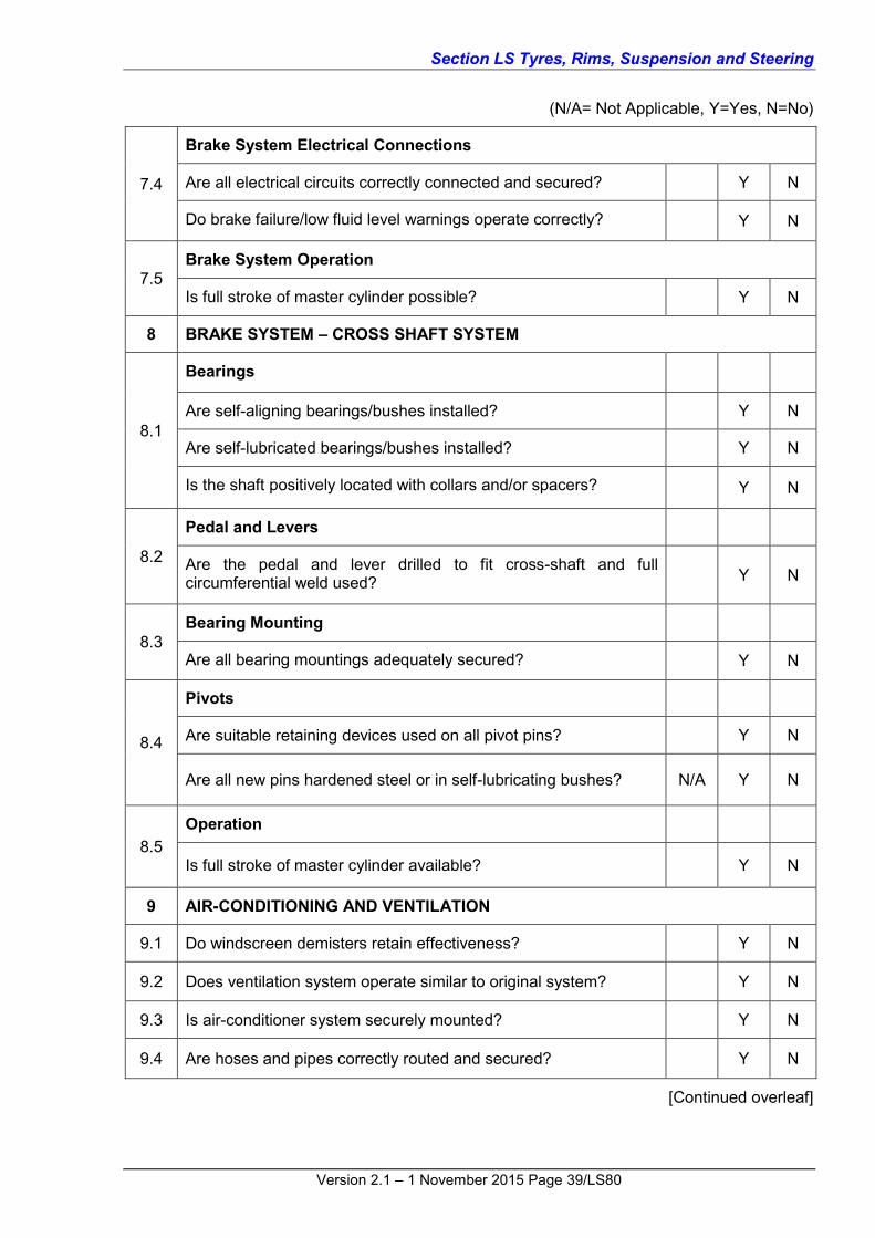
(N/A= Not Applicable, Y=Yes, N=No)
7.4
Brake System Electrical Connections
Are all electrical circuits correctly connected and secured? Y N
Do brake failure/low fluid level warnings operate correctly? Y N
7.5 Brake System Operation
Is full stroke of master cylinder possible? Y N
8 BRAKE SYSTEM – CROSS SHAFT SYSTEM
8.1
Bearings
Are self-aligning bearings/bushes installed? Y N
Are self-lubricated bearings/bushes installed? Y N
Is the shaft positively located with collars and/or spacers? Y N
8.2
Pedal and Levers
Are the pedal and lever drilled to fit cross-shaft and full circumferential weld used? Y N
8.3 Bearing Mounting
Are all bearing mountings adequately secured? Y N
8.4
Pivots
Are suitable retaining devices used on all pivot pins? Y N
Are all new pins hardened steel or in self-lubricating bushes? N/A Y N
8.5 Operation
Is full stroke of master cylinder available? Y N
9 AIR-CONDITIONING AND VENTILATION
9.1 Do windscreen demisters retain effectiveness? Y N
9.2 Does ventilation system operate similar to original system? Y N
9.3 Is air-conditioner system securely mounted? Y N
9.4 Are hoses and pipes correctly routed and secured? Y N
[Continued overleaf]

Section LS Tyres, Rims, Suspension and Steering
Version 2.1 – 1 November 2015 Page 40/LS80
(N/A=Not Applicable, Y=Yes, N=No)
10 DASH PANELS AND CONTROLS
10.1 Is crash pad original or equivalent? Y N
10.2 Are instruments and controls correctly positioned for the driver? Y N
11 ELECTRICAL WIRING
11.1 Are connections, size, insulation, support and protection at least equivalent to original? Y N
12 WINDSCREEN WIPERS
12.1 Are windscreen wipers fitted in accordance with the Design specifications? Y N
Note: If the answer to any question is N (No), the modification cannot be certified under Code LS2.
CERTIFICATION DETAILS
Make Model Year of Manufacture
VIN
Chassis Number (If applicable)
Brief Description of Modification/s
Vehicle Modified By
Certificate Number (If applicable)
Vehicle Certified By (Print)
Signatory’s Employer (If applicable)
Signatory’s Signature Date

Section LS Tyres, Rims, Suspension and Steering
Version 2.1 – 1 November 2015 Page 41/LS80
FRONT SUSPENSION AND STEERING MODIFICATION (DESIGN) CODE LS3
SCOPE Code LS3 provides for the preparation of designs that may be approved by Registration Authorities for use by other signatories or modifiers. The designs under Code LS3 cover the design of modifications to the front suspension and steering.
Code LS3 does not apply to ADR category L-group vehicles and motor cycles. DESIGNS COVERED UNDER CODE LS3 The following is a summary of the designs that may be prepared under Code LS3:
Design of power steering conversions using components from different vehicle model(s);
Design of rack and pinion steering conversions;
Design of front suspension modifications using different struts or uprights;
Design of conversions using a complete suspension and steering assembly from a different vehicle model;
Alternative wheel and tyre specifications for vehicles with modified axles or suspension; and
Design of RHD to LHD steering and dual steering conversions.
DESIGNS NOT COVERED UNDER CODE LS3 The following are designs that are not covered under Code LS3:
Designs for vehicles originally equipped with ESC that have not been approved by the vehicle manufacturer or proven through testing;
Designs that as a consequence of a single modification or a combination of modifications, result in a change of vehicle height exceeding 50mm (this is covered by Code LS7);
Design of left to right hand drive steering conversions (these are covered by Code LS1);
Certification of the actual vehicle modifications (this is covered by Code LS4); and
Designs for rear suspension modifications (these are covered by Code LS5).
COMPLIANCE WITH APPLICABLE VEHICLE STANDARDS Modified vehicles must continue to comply with the ADRs to which they were originally constructed, except as allowed for in the AVSR. These modified vehicles must also comply with the applicable in-service requirements of the AVSR. This is not an exhaustive list and other modifications may also affect ADR compliance.
Modified pre-ADR vehicles must continue to comply with the AVSR.
Compliance with the AVSR also means compliance with the equivalent regulations of a State or Territory of Australia.
Outlined in Table LS6 below are areas of the vehicle that may be affected by the modifications and that may require re-certification, testing and/or data to show compliance for the modified vehicle
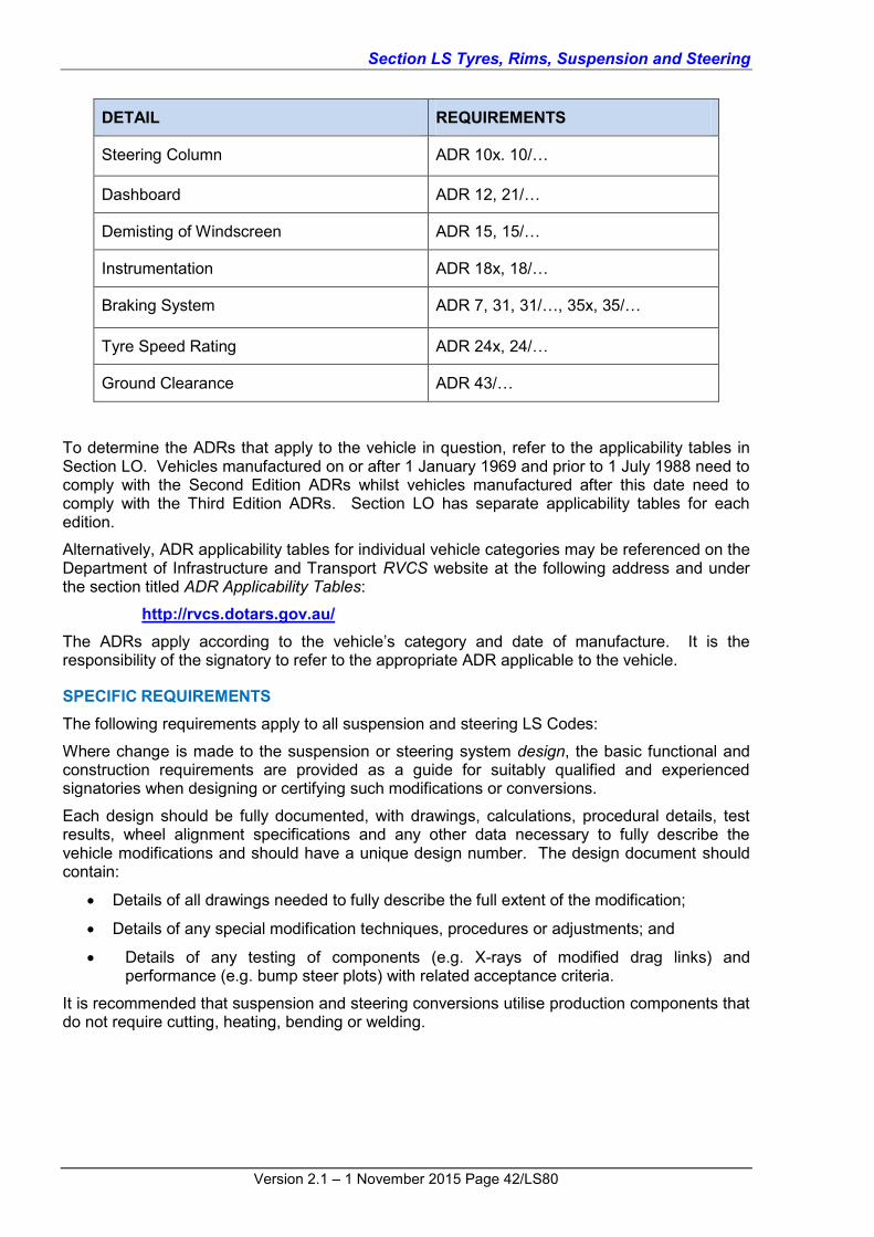
Table LS6 Summary of items that if modified, may detrimentally affect compliance with applicable ADRs
Section LS Tyres, Rims, Suspension and Steering
Version 2.1 – 1 November 2015 Page 42/LS80
DETAIL REQUIREMENTS
Steering Column ADR 10x. 10/…
Dashboard ADR 12, 21/…
Demisting of Windscreen ADR 15, 15/…
Instrumentation ADR 18x, 18/…
Braking System ADR 7, 31, 31/…, 35x, 35/…
Tyre Speed Rating ADR 24x, 24/…
Ground Clearance ADR 43/…
To determine the ADRs that apply to the vehicle in question, refer to the applicability tables in Section LO. Vehicles manufactured on or after 1 January 1969 and prior to 1 July 1988 need to comply with the Second Edition ADRs whilst vehicles manufactured after this date need to comply with the Third Edition ADRs. Section LO has separate applicability tables for each edition.
Alternatively, ADR applicability tables for individual vehicle categories may be referenced on the Department of Infrastructure and Transport RVCS website at the following address and under the section titled ADR Applicability Tables:
http://rvcs.dotars.gov.au/ The ADRs apply according to the vehicle’s category and date of manufacture. It is the responsibility of the signatory to refer to the appropriate ADR applicable to the vehicle.
SPECIFIC REQUIREMENTS The following requirements apply to all suspension and steering LS Codes:
Where change is made to the suspension or steering system design, the basic functional and construction requirements are provided as a guide for suitably qualified and experienced signatories when designing or certifying such modifications or conversions.
Each design should be fully documented, with drawings, calculations, procedural details, test results, wheel alignment specifications and any other data necessary to fully describe the vehicle modifications and should have a unique design number. The design document should contain:
Details of all drawings needed to fully describe the full extent of the modification;
Details of any special modification techniques, procedures or adjustments; and
Details of any testing of components (e.g. X-rays of modified drag links) and performance (e.g. bump steer plots) with related acceptance criteria.
It is recommended that suspension and steering conversions utilise production components that do not require cutting, heating, bending or welding.

Section LS Tyres, Rims, Suspension and Steering
Version 2.1 – 1 November 2015 Page 43/LS80
1 SUSPENSION AND STEERING GEOMETRY Modified or redesigned suspension systems should meet the following requirements:
Free Movement. Suspension members and pivot bushes must be free to move through the full range of suspension travel from metal to metal positions at full bump and full rebound, without any geometric binding within the linkage and without any pivot being articulated beyond its design angles. This requirement applies when one wheel is at full bump and the opposite side wheel is at full rebound;
Roll Centre. The vehicle’s roll axis is determined by the relative roll centre heights of the front and rear suspensions. A higher roll centre will reduce body roll but can result in unsatisfactory track variations and camber change on independent suspensions. The front suspension roll centre should not be higher than the rear suspension roll centre;
Camber and Track Change. The suspension design should minimise track change with vertical wheel travel and maintain the outside wheel as close to vertical (or at slightly negative camber) as the body rolls under cornering. This will maximise cornering adhesion and minimise tyre wear;
Anti-squat, anti-dive. The amount of anti-dive geometry at the front suspension and anti-squat geometry at the rear is a matter of choice, depending on the vehicle characteristics desired. The pitch axis of the front suspension should be behind the front wheels while that for the rear suspension should be ahead of the rear wheels;
Vertical Wheel Travel. Spring rates and damper settings need to be selected to suit the character required for the vehicle. Spring rates should not be so high that an uncomfortably firm ride is achieved while they should not be so low that vehicle handling is compromised. Similarly damper settings should be selected to complement the spring rates. The latter may require some development effort. In general, the more vertical wheel-travel the better, because it allows larger wheel movements before bump rubbers are contacted;
Bump steer. When a wheel turns or steers as a result only of vertical suspension movement, this behaviour is called bump steer. A wheel can also steer as a result of longitudinal wheel movement in longitudinally compliant suspensions.
The bump steer characteristic must be selected to suit the entire vehicle dynamics and should be established in conjunction with the rear suspension bump steer characteristics. As a guide, a very small toe-out on bump will produce a stable understeer characteristic. The toe-out must not be excessive because it produces unresponsive steering and tyre wear. Front wheels should never toe-in on bump (unless the rear suspension also toes-in) because this causes unstable oversteer.
When the front wheels are deflected rearwards under the influence of road shocks, the wheel direction should either remain unchanged or should toe out slightly. Toe-out under these conditions produces a smoother ride. However too much can cause excessive tyre wear.
Ball joint operating angles. The complete range of combinations of steering/suspension travel must be considered to ensure that there is no possibility of joints being over-articulated.
Over-articulation, even by a small amount can result in joint failure. An allowance must be made for deflection of suspension bushes under dynamic loading, as this can be significant at the extremes of travel. The compound angle of articulation of all steering and suspension ball joints must be established and compared with the manufacturer’s specification for each joint.
Note: The specification will usually quote a slightly smaller angle than might be measured using a production component.

Section LS Tyres, Rims, Suspension and Steering
Version 2.1 – 1 November 2015 Page 44/LS80
Operating Clearances. All suspension members and steering levers and linkages must clear other vehicle components such as engine, transmission exhaust system and chassis members etc. over the full envelope of steering/suspension travel, after allowing for any likely movement of engine or other mechanical assembly. It is recommended that a clearance of at least 10mm be provided between these components and 25mm be provided for tyres.
Track. Where non-original axle or suspension cross-member components are fitted, the offset of the wheel in relation to the axle or hub assembly used must not be increased by more than 12.5mm each side of the vehicle based on the specifications of the axle components used. If an axle assembly is shortened then the track width limit is taken as the axle manufacturers original track dimension, less the amount the assembly has been narrowed, plus 25mm.
Linkage stability. Steering linkages must be evaluated to ensure that they cannot over-centre at any stage, under the influence of either steering gear forces or road wheel forces. Allowance must be made for significant deflection and wear in pivot bushes in the steering and suspension and a large safety margin must be maintained.
Steering stops. Must be provided and be installed as per those from the donor vehicle or as approved by the steering gear manufacturer. Reductions in steering gear travel must be designed to ensure that operating loads or stresses on the steering system are not increased.
Ackermann principle. The Ackermann principle ensures accurate wheel geometry and tyre contact in turns avoiding excessive scuffing. All vehicles should incorporate a reasonable degree of Ackermann steering geometry. This concept is important when designing replacement steering systems and when altering the wheelbase of vehicles, e.g. limousine conversions.
At full lock, the lock angles must be appropriate for the desired turning circle and must not change significantly over the range of suspension travel. The toe-out at full lock should be selected, bearing in mind the true Ackermann angle, the types of tyres to be catered for and the use intended for the vehicle.
At partial lock, the toe-out should be suitable for the vehicle application. This usually means slightly less than the true Ackermann angle due to the operating slip angle of the outside front tyre.
2 STRUCTURE The body/chassis structure should meet the following requirements:
Body/Chassis. Reinforcements must be added to achieve comparable structural strength and stiffness at body attachment points whenever a replacement suspension or steering system from a different vehicle model is used. The modifications must not create local stress concentrations; and
Cross-member. When a cross-member is modified, or when a cross-member from another vehicle model is fitted, it must be reinforced where necessary to maintain its original structural strength and stiffness.
3 COMPONENT STRESS LEVELS The stress levels of any production component in the suspension system must not be increased over that at which it has been demonstrated to be capable of satisfactory operation.
Stress analysis should be carried out for modified or specially fabricated components and the following load conditions are suggested as a guide:
bump loads: 4g vertical;
Section LS Tyres, Rims, Suspension and Steering
Version 2.1 – 1 November 2015 Page 45/LS80
rut loads: 1g vertical combined with 0.6g lateral; and
skid loads: 2g vertical combined with 1.2g skid (longitudinal).
Overturning loads: 2g vertical combined with 2.5g overturning; where g is the static load at the tyre contact patch when the vehicle is stationary. The stress levels that are acceptable under these conditions will depend on the materials and the number of times in the life of the vehicle that the loads can be expected to occur. Other factors which can affect suspension loads and should be considered are:
rim offset;
combination of braking at lock while striking an obstacle;
steering scrub radius; and
the effect of steering system loads on the suspension components.
4 MODIFIED COMPONENTS Where modifications of steering components cannot be avoided, the operations employed should be determined and controlled such that the final properties can be predicted and verified on an individual component basis by a NATA approved materials laboratory, using relevant Australian or International Standards as a reference. The following post process testing by the laboratory is a minimum for such components:
Welded parts should have the weld material identified, a hardness test traversing across the weld area including the heat affected zone, an X-Ray inspection and a statement of weld integrity;
Heated parts should be stress relieved, heat treated to a defined specification and undergo non-destructive testing such as magnetic particle or ultrasonic;
Parts which have been cold worked (where permitted) must be checked to ensure that the cold working is not excessive, stress relieved if required and undergo non-destructive testing such as magnetic particle or ultrasonic.
Section LZ Appendices provides further information and guidance on heat treatment and welding. The mandatory provisions of Section LZ must be complied with.
4.1 Standard Features Standard features such as splines, tapers and keyways must conform to published standards and mating parts to matching standards.
4.2 Machining of Input Shafts Machining of input shafts is allowable to reduce length, provided that welding is not involved, the same spline is machined at the new length and the minimum cross section, including radii, of the shaft is not reduced below that of the original. The modified pinion shaft should not be subsequently heat-treated.
4.3 Machining of Any Components Machining of any components must meet the relevant specifications of tolerance and radii.
4.4 All Splines All splines must meet the original vehicle specifications and must engage over the same length as the original.
4.5 Threaded Bosses Threaded bosses where used for steering gear mounting, must provide full depth thread for engagement over 1.5 times the mating bolt diameter.

Section LS Tyres, Rims, Suspension and Steering
Version 2.1 – 1 November 2015 Page 46/LS80
4.6 Welding of Steering Components to Chassis Steering components must not be welded to the chassis structure.
4.7 Re-machining of Ball Joint Tapered Stud Holes in Steering Arms Re-machining of ball joint tapered stud holes in steering arms may be undertaken provided that the re-machining does not reduce the safety of the design and the surface finish is equivalent to that of the original manufacture.
4.8 Tapered Adaptor Sleeves Tapered adaptor sleeves may be used provided they are made of suitable steel, i.e. equivalent in strength and hardness to the stud to be mounted.
4.9 Mounting Surfaces Mounting surfaces for steering components must designed and in a condition that ensures no stress inducing deflection of either mounting surface or steering component occurs when the attachment bolts are tightened.
4.10 Braces Braces if required to achieve appropriate steering box/rack mounting stiffness, may be bolted into position to allow easy removal for subsequent vehicle servicing or dismantling.
4.11 Power Steering Conversions – Separate Ram Type Power steering conversions – separate ram type, must be carried out in accordance with the following:
Power cylinder location, orientation, articulation angles and operating pressures must be in accordance with the manufacturer’s specifications, taking into consideration the full movement of the suspension and steering; and
The vehicle structure at the point of attachment of the power steering ram must be reinforced if required to accommodate the power cylinder loads, taking into consideration the peak hydraulic pressures, mounting bush deflection loads and the frequency of application of these loads.
4.12 Steering Linkage Steering linkage installations must be carried out in accordance with the following:
Steering gear linkage assemblies must be sourced from a vehicle of similar or larger mass than the finished vehicle as modified;
Reshaping, sectioning, re-machining of draglinks, steering arms and the relocation of the inner and outer pivots or tie-rod pivots in order to achieve correct steering geometry may be done, provided that the processes are conducted under the controls described in this section; and
Ball joints and plain bearing end fittings and idler arm pivots must have manufacturer’s ratings in excess of the loads and angular travel imposed on them in the modified vehicle. If the manufacturer’s rating is not available, evidence of equivalent usage in a production vehicle, together with stress calculations may be used.
4.13 Rack and Pinion Steering Gear Rack and pinion steering gear installations must be carried out in accordance with the following:
Rack and pinion assemblies must be sourced from a vehicle of similar or larger mass than the vehicle being modified;
Rack and pinion type steering must not be used in conjunction with beam front axles if the independent arcs of the tie rods (upon suspension movement of the axle) creates toe-in or toe-out with suspension movement resulting in dangerous bump steer;

Section LS Tyres, Rims, Suspension and Steering
Version 2.1 – 1 November 2015 Page 47/LS80
Any rack extension (to achieve correct steering geometry) must be by means of machined adaptors provided that they are of the same strength as the steering rack. Retention of such adaptors must be identical to that of the original tie rods together with suitable thread securing compound. Steering racks must not be welded. The effects on rack bending stresses of the additional ball joint offset as well as the strength of the connection between rack and adaptor must be assessed in accordance with this sub-section. Rack boot requirements must also be addressed;
Rack shafts may be shortened by machining provided that the machining does not affect the teeth area;
For variable ratio racks, any shortening must be performed at each end symmetrically to maintain the on-centre rack location with the road wheels straight ahead;
A rack shaft must not be shortened by cutting and re-welding;
Rack housing length may be shortened. It is recommended that only housings in which the centre section is a steel tube are so modified and that the shortening be confined to this section. It is suggested that a close fitting steel sleeve of equivalent material and wall thickness be used to bridge the joint and be welded on both ends;
On assembly, the preload of the rack must be checked every 25mm of rack travel to ensure no binding has resulted from the rework. The rack manufacturer’s preload specification should be used; and
Mounting of the rack should replicate the original mounting configuration.
4.14 Chassis Mounted Steering Gear Chassis mounted steering gear installations must be carried out in accordance with the following:
Chassis mounted steering gear assemblies must be sourced from a vehicle of similar or larger mass than the finished vehicle as modified;
Unless the steering column is aligned with the steering gear with no more than 5 of angular mismatch, fabric or rubber couplings may not be used at the steering gear input shaft. Where more than a 5 angular mismatch exists, a metallic universal joint may be used. If the axes of the column and steering gear input shaft do not intersect at the position of the coupling, an intermediate shaft must be fitted with two universal joints to provide for the misalignment;
Sector shafts may be reworked only by re-machining the master splines. The re-machined spline must replicate the remaining splines in all dimensions;
Sector shafts must not be welded to change length or to alter spline details, and
Where new chassis mounting boltholes are required, the chassis must be reinforced to carry the steering gear loads and the boltholes in box section chassis rails must be reinforced with tubes of 1.6mm wall thickness minimum to prevent crushing of the chassis section.
4.15 Pitman Arms Pitman arms may be modified by:
the removal by machining of the master spline; and/or
cold working, hot working, sectioning and re-welding, provided that the processes are conducted under the controls described in this section.
4.16 Idler Arms Idler arms may be modified by:

Section LS Tyres, Rims, Suspension and Steering
Version 2.1 – 1 November 2015 Page 48/LS80
re-machining to accept revised pivots, provided that the strength of the component is sufficient to accept the maximum input load that can be applied by the steering gear; and/or
cold forming, hot reforming and sectioning and re-welding are allowable provided that the processes are conducted under the controls described in this section.
4.17 Tie-rods Tie Rods may be modified by:
shortening by extending the thread and removing the excess threaded portion, provided that the rod is suitable for this operation, the length of thread engagement is equal to or greater than the original manufacturer’s specification; or
extending by provision of threaded adaptors, provided that the original manufacturer’s specification in respect to buckling strength, shear strength, thread engagement, thread locking and material selection are all maintained.
4.18 Steering Arms Steering arms may be modified by hot-working, provided that the processes are conducted under the controls described in this section.
4.19 Draglink Draglink specific requirements are:
A new draglink may be manufactured provided that it is one continuous length of material between end fittings and the selected material is suitable for the design and method of manufacture; and
Sectioning and re-welding of the draglink must always be performed in accordance with the processes and controls described in this section.
4.20 Steering column Shaft Couplings Steering column shaft couplings must be selected and installed as follows:
Couplings which are designed for use on manual steering may be used on power steering vehicles;
Couplings designed for use on power steering vehicles only, are not to be used on manual steering vehicles;
Re-assembly of steering couplings utilising revised components must ensure that the resulting assembly has the torsional strength to withstand an applied torque of 200Nm;
Machining of couplings to alter the PCD of the attaching bolts must ensure that the resulting assembly has the torsional strength to withstand an applied torque of 200Nm; and
The alignment of the coupling must be maintained to within the manufacturer’s specification and phasing of the universal joints must be correct.
4.21 Intermediate Shafts Intermediate shafts must be selected and installed as follows:
Intermediate shafts designed for use only on power steering vehicles must not to be used on manual steering vehicles;
Collapsible intermediate shafts designed in conjunction with a specific steering column to meet ADR 10 should be utilised with a matching column where the vehicle is subject to that ADR;

Section LS Tyres, Rims, Suspension and Steering
Version 2.1 – 1 November 2015 Page 49/LS80
Machining may be carried out to accept a revised PCD for coupling attachment and/or to match a revised spline, provided that the resulting assembly and the modifications do not reduce the available collapse distance required to meet ADR 10;
Intermediate shafts may be sectioned and welded, provided that the processes are conducted under the controls described in this section. The weld should be ground smooth. The joint may be supplemented with a fitted sleeve spanning the welded area and attached by plug welding and/or fillet welding at each end; and
The completed intermediate shaft must be straightened to achieve a maximum runout of 1mm Total Indicated Runout (TIR) and achieve the torsional strength to withstand an applied torque of 200Nm.
4.22 Steering Columns Steering columns must be selected and installed as follows:
Steering column assemblies should be sourced from a vehicle of similar mass and specification as the vehicle being modified and, where ADR 10 applies, the column must have the design features and be suitably mounted to achieve this;
Steering column shafts may be machined to accept revised splines;
If it is necessary to weld an alternative coupling flange to the lower end of the steering column shaft, both the shaft and flange materials must be suitable for the welding process used and successfully undergo appropriate non-destructive testing;
The modified steering column must achieve the torsional strength to withstand an applied torque of 200Nm;
All steering column shafts must be adequately supported, particularly where universal joints are used;
Angles on universal joints in multi-column assemblies (sometimes fitted to clear other components) must not be greater than the universal joint manufacturer’s specifications. Generally, the maximum angle is 30 to avoid excessive stress on the unit; and
Flexible couplings within steering column systems, otherwise known as rag, fabric or rubber steering dampers, must not be used for direction change in the steering column shaft. Any change of direction must be made by the use of suitable steel universal or constant velocity joints.
4.23 Change in Vehicle Height. Where changes in vehicle height occur as a result of modifications, the requirements detailed under Modified Components above that are applicable to individual steering and suspension components continue to apply. Important items such as spline engagement, operating angles of drive shaft joints and in the case of CV joints, the range of axial movement, must remain within design limits for the full range of suspension travel. Also other components such as gear levers, brake hoses etc. may need to be extended depending on the nature of the lift.
Steering linkages must continue to operate efficiently and sufficient spline contact surface must be retained for the full range of suspension travel to ensure the safe operation of the vehicle. Otherwise an appropriate steering shaft extension must be used.
Following the completion of modifications the vehicle attitude must remain as per original specifications – i.e. the original relationship between the front and rear suspension heights must not be changed and therefore the front and rear suspensions must be both raised by the same amount.
Vehicles whose ride height is raised by more than 50mm must undergo a lane-change manoeuvre test in accordance with ISO 3888-1 Passenger Cars – Test Track for a Severe Lane-Change Manoeuvre – Part 1: Double Lane-Change to ensure its stability has not been compromised

Section LS Tyres, Rims, Suspension and Steering
Version 2.1 – 1 November 2015 Page 50/LS80
This page is intentionally blank

Section LS Tyres, Rims, Suspension and Steering
Version 2.1 – 1 November 2015 Page 51/LS80
CHECKLIST LS3 FRONT SUSPENSION AND STEERING MODIFICATION (DESIGN)
CODE LS3 (N/A=Not Applicable, Y=Yes, N=No)
1 REPLACEMENT STEERING BOX OR RACK
1.1
Steering Box/Rack Selection Is the specified RHD steering box/rack of equivalent capacity to the original? Y N
Is the Pitman arm size/length and arc of travel equivalent to the original? N/A Y N
Does the Pitman arm spline match the steering box spline? N/A Y N
Is the drag link attachment taper identical? N/A Y N
1.2 Steering Rack Modification Are all modifications as per the Specific Requirements detailed in Code LS3? N/A Y N
1.3
Steering Box/Rack Mounting
Does location and angle of steering box/rack replicate original? Y N
Will the chassis rail be reinforced and fitted with steel sleeves? N/A Y N
Is mounting of steering box/rack equivalent strength to original? Y N
1.4
Steering Box/Rack coupling
Will the original column coupling (or equivalent) be used? Y N
Will the original steering box/rack coupling (or equivalent) be used? Y N
1.5
Idler arm
Does the design ensure that the mounting brackets will be adequately secured to chassis rail? N/A Y N
Does the design idler arm location and angle replicate the original? N/A Y N
Are mounting bolts replaceable? N/A Y N
[Continued overleaf]

Section LS Tyres, Rims, Suspension and Steering
Version 2.1 – 1 November 2015 Page 52/LS80
(N/A=Not Applicable, Y=Yes, N=No)
1.6
Drag link
Is the original drag link to be used without modification? or N/A Y N
Is the original drag link to be used without modification? or N/A Y N
Are the proposed modifications as per VSB 4 requirements? N/A Y N
1.7
Steering geometry
Will the turning circle in both directions remain within legal limits?
Y N
Has the original geometry been replicated in the new configuration? or N/A Y N
If the geometry is to be altered, will the bump steer still be within specified limits? N/A Y N
2 REPLACEMENT FRONT SUSPENSION CROSS-MEMBER SUSPENSION AND STEERING
2.1
Cross member Mounting
Have the cross member mountings been designed to be at least equivalent in strength to the original mountings? N/A Y N
Will the chassis rail be reinforced and fitted with steel sleeves? N/A Y N
2.2 Design Loadings
Do all components have adequate strength for the application? Y N
3 REPLACEMENT FRONT SUSPENSION STRUTS OR UPRIGHTS
3.1
Ball Joints and Tie-rod Ends
Are all ball joint tapers compatible or to be modified in accordance with Code LS3 requirements? N/A Y N
3.2
Steering geometry
Will the turning circle in both directions remain within legal limits? Y N
Has the original geometry been replicated in the new configuration? or N/A Y N
If the geometry is to be altered, will the bump steer still be within specified limits? N/A Y N
[Continued overleaf]

Section LS Tyres, Rims, Suspension and Steering
Version 2.1 – 1 November 2015 Page 53/LS80
(N/A=Not Applicable, Y=Yes, N=No)
4 STEERING COLUMN
4.1
Mounting
Have support brackets been designed to be equivalent in strength to the original brackets? Y N
4.2
Intermediate Shaft
Will the modified shaft meet Code LS3 requirements? N/A Y N
If applicable, do the specified couplings and attachments meet the requirements of VSB 4? N/A Y N
4.3
Collapse Operation
Does the specified column installation retain its designed collapse system? N/A Y N
Are the original telescopic sections to be left unmodified? N/A Y N
5 LHD STEERING CONVERSION USING LHD STEERING BOX OR RACK
5.1
Drag link
Is the original left hand drive drag link to be used without modification? or N/A Y N
Is the original right hand drive drag link to be used without modification? or N/A Y N
Does the designed modified drag link replicate the original? N/A Y N
Are modifications designed in accordance with the specific requirements of Code LS3? N/A Y N
5.2
Steering geometry
Will the turning circle in both directions be retained? Y N
Is original geometry replicated in right hand drive form? N/A Y N
If geometry is altered, is bump steer still within specified limits? N/A Y N
[Continued overleaf]

Section LS Tyres, Rims, Suspension and Steering
Version 2.1 – 1 November 2015 Page 54/LS80
(N/A=Not Applicable, Y=Yes, N=No)
6 LHD OR DUAL STEERING CONVERSION USING A CROSS SHAFT
6.1
Right angle gearboxes
Are boxes to be used designed for automotive steering application? Y N
Are the input and output shafts splined? Y N
Does the design allow for the gearboxes to be securely mounted and correctly aligned? Y N
6.2
Couplings and Cross Shaft
Is cross shaft articulated at both ends? Y N
Does the design allow for the couplings to correctly mate with the gearbox shafts? Y N
6.3 Design Loadings
Do all components have adequate strength for the application? Y N
7 LHD OR DUAL STEERING CONVERSION USING A CHAIN-DRIVE
7.1 Is the selected chain drive unit designed for automotive steering application? Y N
7.2 Is the unit fully enclosed with provision for chain adjustment? Y N
7.3 Has at least duplex chain been specified with provision for adequate lubrication provided? Y N
7.4 Is the drive designed to withstand at least 200 Nm input torque? Y N
7.5 Are shaft connections to manufacturer’s specification and/or are splines and cotter bolts sufficiently engaged? Y N
7.6 Does the design allow for the chain-drive unit and steering column to be adequately supported? Y N
8 BRAKE MASTER CYLINDER RELOCATION
8.1
Firewall Modifications
Is the strength and stiffness of the left hand side firewall at least equivalent to the original design? Y N
Are all firewall openings sealed? Y N
8.2
Pedal Mountings
Is strength and stiffness of replacement or modified pedal mounting bracket at least equivalent to original design? N/A Y N
[Continued overleaf]

Section LS Tyres, Rims, Suspension and Steering
Version 2.1 – 1 November 2015 Page 55/LS80
(N/A=Not Applicable, Y=Yes, N=No)
8.3
Brake Pedal
Is the original pedal used unmodified? or N/A Y N
Is a replacement pedal of equivalent strength to original design? N/A Y N
8.4
Operation
Is full stroke of the master cylinder possible? Y N
Is the pedal lever ratio the same as original? Y N
9 BRAKE CROSS SHAFT SYSTEM
9.1
Strength
Has the system been checked or designed to be capable of transferring the design brake forces? N/A Y N
Will the deflection of the cross shaft at maximum torque remain within specified limits? N/A Y N
9.2
Bearings
Are self-aligning bearings/bushes specified? N/A Y N
Are self-lubricated bearings/bushes specified? N/A Y N
Does the design allow for the cross shaft to be positively located with collars and/or spacers? N/A Y N
9.3
Pedal and Levers
Are pedal and lever drilled for cross shaft attachment and full circumferential welds used? N/A Y N
9.4
Bearing mounting
Are bearing mountings adequately specified? N/A Y N
Do bearing mountings have adequate stiffness? N/A Y N
9.5
Pivots
Have the original pivot pins been specified? or N/A Y N
Are all new pins to be made of hardened steel or in self-lubricating bushes? N/A Y N
Have suitable retaining devices been specified for all pivot pins? N/A Y N
[Continued overleaf]

Section LS Tyres, Rims, Suspension and Steering
Version 2.1 – 1 November 2015 Page 56/LS80
(N/A=Not Applicable, Y=Yes, N=No)
10 WINDSCREEN WIPERS
10.1 Does the wiper and wiper pattern design meet the requirements of VSB 4? N/A Y N
11 DESIGN INCLUDING WELDING AND FASTENERS
11.1 Does the design of the conversion comply with all of the requirements outlined in Code LS3 and VSB 4 as applicable? Y N
11.2
Has all work, that has been specified in the certification of the LS3 design, been determined in accordance with recognised engineering standards and the relevant Appendices of Section LZ Appendices?
N/A Y N
11.3 If the vehicle is to be raised, have all components affected by the lift such as gear levers, brake hoses etc. been designed to comply with Code LS3?
N/A Y N
11.4
If the vehicle is to be raised, have all items affected by the lift such as drive shaft joint operating angles, spline engagement and axial movement of CV joints been either checked or designed to be within design limits over the entire suspension travel?
N/A Y N
11.5 Will the vehicle been raised by no more than 50mm following the completion of all modifications including changes to tyre size? N/A Y N
11.6 If the vehicle was originally equipped with ESC and if the modification affects the ESC has the ESC system been adjusted and tested and found to operate satisfactorily?
N/A Y N
Note: If the answer to any question is N (No), the design cannot be certified under Code LS3.
[Continued overleaf]

Section LS Tyres, Rims, Suspension and Steering
Version 2.1 – 1 November 2015 Page 57/LS80
CERTIFICATION DETAILS
Make Model Year of Manufacture
VIN
Chassis Number (If applicable)
Brief Description of Modification/s
Vehicle Modified By
Certificate Number (If applicable)
Vehicle Certified By (Print)
Signatory’s Employer (If applicable)
Signatory’s Signature Date

Section LS Tyres, Rims, Suspension and Steering
Version 2.1 – 1 November 2015 Page 58/LS80
FRONT SUSPENSION AND STEERING MODIFICATION CODE LS4
SCOPE Code LS4 covers modifications to the front suspension and steering. The modifications may be carried out in conformity with designs approved by a Registration Authority under Code LS3.
Code LS4 does not apply to ADR category L-group vehicles and motor cycles. MODIFICATIONS COVERED UNDER CODE LS4 The following is a summary of the modifications that may be performed under Code LS4:
Power steering conversions using components from different vehicle model(s);
Rack and pinion steering conversions;
Front suspension modification using different struts or uprights;
Conversions using a complete suspension and steering assembly from a different vehicle model;
Fitting wheels and tyres to vehicles with modified axles or suspension; and
RHD to LHD steering and dual steering conversions.
MODIFICATIONS NOT COVERED UNDER CODE LS4 Modifications not covered under this Code are listed below:
LHD to RHD steering conversions;
Rear suspension modifications; and
Change of vehicle height exceeding 50mm as a consequence of a single modification or a combination of modifications, (this is covered by Code LS8).

Section LS Tyres, Rims, Suspension and Steering
Version 2.1 – 1 November 2015 Page 59/LS80
CHECKLIST LS4 FRONT SUSPENSION AND STEERING MODIFICATION
CODE LS4 (N/A=Not Applicable, Y=Yes, N=No)
1 DESIGN
1.1 Insert Design Number………………………(the Design)
1.2 Has the vehicle been modified exactly in accordance with the plans and specifications issued under the LS3 Design Number given above?
N/A Y N
2 WORKMANSHIP INCLUDING WELDING AND FASTENERS
2.1 Is all work, including welding, of satisfactory quality and has all work been performed in accordance with recognised engineering standards?
N/A Y N
2.2 Do all new or replaced fasteners comply with the applicable requirements of Section LZ Appendices, Appendix A Fasteners? Y N
2.3 Does the quality of welding comply with the applicable requirements of Section LZ Appendices, Appendix C Heating and Welding of Steering Components?
Y N
3 STEERING
3.1 Steering Box Mounting
Is chassis rail reinforced and fitted with steel sleeves? N/A Y N
3.2
Drag Link
If modified, does drag link comply with Code LS4 requirements? N/A Y N
Are weld X-ray and hardness results satisfactory? N/A Y N
3.3 Steering Rack
If modified, does the rack comply with Code LS4 requirements? N/A Y N
3.4
Steering Geometry
Is turning circle in both directions within specified and legal limits? Y N
Is the amount bump steer still within specified limits? N/A Y N
[Continued overleaf]

Section LS Tyres, Rims, Suspension and Steering
Version 2.1 – 1 November 2015 Page 60/LS80
(N/A=Not Applicable, Y=Yes, N=No)
3.5
Wheel Alignment
Have all wheels been aligned in accordance with the Design specifications? N/A Y N
4 SUSPENSION
4.1
Cross-member Mounting
Is cross-member mounted in accordance with the Design? N/A Y N
Is the chassis rail reinforced and fitted with steel sleeves? N/A Y N
4.2
Ball Joints and Tie-rod Ends
Are all ball joint tapers compatible or modified in accordance with certified the Design requirements? N/A Y N
5 LHD OR DUAL STEERING CONVERSION
5.1 Does the conversion comply with all applicable requirements outlined in this Code LS4 and VSB 4? N/A Y N
6 MODIFICATIONS RESULTING IN VEHICLE HEIGHT INCREASE
6.1 If the vehicle has been raised, have all components affected by the lift such as gear levers, brake hoses etc. been modified and fitted to comply with Code LS4?
N/A Y N
6.2
If the vehicle has been raised, have all items affected by the lift such as drive shaft joint operating angles, spline engagement and axial movement of CV joints been checked and found to be within design limits over the entire suspension travel?
N/A Y N
6.3 Has the vehicle been raised by no more than 50mm following the completion of all modifications including changes to tyre size? N/A Y N
6.4 If the vehicle was originally equipped with ESC and if the modification affects the ESC, has the ESC system been adjusted and tested and found to operate satisfactorily?
N/A Y N
Note: If the answer to any question is N (No), the modification cannot be certified under Code LS4.
[Continued overleaf]

Section LS Tyres, Rims, Suspension and Steering
Version 2.1 – 1 November 2015 Page 61/LS80
CERTIFICATION DETAILS
Make Model Year of Manufacture
VIN
Chassis Number (If applicable)
Brief Description of Modification/s
Vehicle Modified By
Certificate Number (If applicable)
Vehicle Certified By (Print)
Signatory’s Employer (If applicable)
Signatory’s Signature Date

Section LS Tyres, Rims, Suspension and Steering
Version 2.1 – 1 November 2015 Page 62/LS80
REAR SUSPENSION MODIFICATION (DESIGN) CODE LS5
SCOPE Code LS5 provides for the preparation of designs that may be approved by Registration Authorities for use by other signatories or modifiers. The designs under Code LS5 cover the design of rear suspension modifications.
Code LS5 does not apply to ADR category L-group vehicles and motor cycles. DESIGNS COVERED UNDER CODE LS5 The following are designs that may be prepared under Code LS5:
Design of rear beam axle modifications including shortening, differential and axle substitution and revised location arms, rods, bearings, bushes and mountings;
Design of independent rear suspension modifications using different struts, trailing arms or uprights;
Design of a conversion using a complete suspension assembly from a different vehicle model;
Design of a complete rear suspension assembly using components from different vehicle model(s); and
Alternative wheel and tyre specifications for vehicles with modified axles or suspension.
DESIGNS NOT COVERED UNDER CODE LS5 The following are designs that are not covered under Code LS5:
Certification of the actual physical modification of particular vehicles (this is covered by Code LS6);
Design for front suspension modifications (these are covered by Code LS3); and
Designs that as a consequence of a single modification or a combination of modifications, result in a change of vehicle height exceeding 50mm (this is covered by Code LS7).
COMPLIANCE WITH APPLICABLE VEHICLE STANDARDS. Modified vehicles must continue to comply with the ADRs to which they were originally constructed, except as allowed for in the AVSR. These modified vehicles must also comply with the applicable in-service requirements of the AVSR. This is not an exhaustive list and other modifications may also affect ADR compliance.
Modified pre-ADR vehicles must continue to comply with the AVSR.
Compliance with the AVSR also means compliance with the equivalent regulations of a State or Territory of Australia.

Section LS Tyres, Rims, Suspension and Steering
Version 2.1 – 1 November 2015 Page 63/LS80
Outlined in Table LS7 below are areas of the vehicle that may be affected by the modifications and that may require re-certification, testing and/or data to show compliance for the modified vehicle.
Table LS7 Summary of items that if modified, may detrimentally affect compliance with applicable ADRs
DETAIL REQUIREMENTS
Braking System ADR 7, 7/…, 31, 31/…, 35x, 35/…
Tyre Speed Rating ADR 24x, 24/…
Ground Clearance ADR 43/…
To determine the ADRs that apply to the vehicle in question, refer to the applicability tables in Section LO. Vehicles manufactured on or after 1 January 1969 and prior to 1 July 1988 need to comply with the Second Edition ADRs whilst vehicles manufactured after this date need to comply with the Third Edition ADRs. Section LO has separate applicability tables for each edition.
Alternatively, ADR applicability tables for individual vehicle categories may be referenced on the Department of Infrastructure and Transport RVCS website at the following address and under the section titled ADR Applicability Tables:
http://rvcs.dotars.gov.au/ The ADRs apply according to the vehicle’s category and date of manufacture. It is the responsibility of the signatory to refer to the appropriate ADR applicable to the vehicle.
SPECIFIC REQUIREMENTS
1 REAR SUSPENSION
The following requirements must be met for all rear suspension modifications. Where a modification involves a change to the suspension system design, the basic functional requirements for suspension modifications/conversions are provided as a guide to suitably qualified and experienced signatories when designing or certifying such modifications or conversions.
The design should also comply with the general guidelines contained in both sub-section 2 General Requirements and Specific Requirements in Approval Code LS3 Front Suspension and Steering Conversion – Design.
Each design should be fully documented, with drawings, calculations, procedural details, test results, wheel alignment specifications and any other data necessary to fully describe the vehicle modifications and should have a unique design number. The design should contain:
Details of all drawings needed to fully describe the full extent of the modification;
Details of any special modification techniques, procedures or adjustments; and
Details of any testing of components and performance (e.g. bump steer plots) with related acceptance criteria.
It is recommended that rear suspension conversions utilise production components that do not require cutting, heating, bending or welding.

Section LS Tyres, Rims, Suspension and Steering
Version 2.1 – 1 November 2015 Page 64/LS80
2 WATTS LINKAGE, PANHARD ROD A Watts linkage or a Panhard rod can be used for sideways location of a rear axle and should be installed to comply with the following:
It must locate sideways only and allow free movement of the axle in other directions;
A Panhard rod should be mounted so that it is horizontal at the vehicle’s normal ride height. This minimises lateral movement of the axle on full bump or rebound;
Mounting brackets must not interfere with any other vehicle component through the full range of suspension movement.
3 TRACTION AIDS Traction aids attached to a live rear axle near the spring mountings must comply with the following:
The geometry of the system must be compatible with the geometry of the spring and not cause any binding with suspension movement;
Parallel ladder bars which do not provide for body roll without a tendency to twist the axle must not be used for street use when used in conjunction with a torsionally rigid axle. A more suitable arrangement is the 4-link suspension system; and
Under body clearances and ground clearance must be maintained and continue to meet regulation requirements.
4 RELATIONSHIP BETWEEN THE FRONT AND REAR SUSPENSION HEIGHTS Following the completion of modifications the vehicle attitude must remain as per original specifications – i.e. the original relationship between the front and rear suspension heights must not be changed and therefore the front and rear suspensions must be both raised by the same amount.

Section LS Tyres, Rims, Suspension and Steering
Version 2.1 – 1 November 2015 Page 65/LS80
CHECKLIST LS5 REAR SUSPENSION MODIFICATION (DESIGN)
CODE LS5 (N/A=Not Applicable, Y=Yes, N=No)
1 REPLACEMENT REAR BEAM AXLE ASSEMBLY
1.1 Rear axle Beam Selection
Is the axle assembly at least of equivalent capacity to original? Y N
1.2
Rear axle modifications
Are the proposed modifications in accordance with the specific requirements detailed in Code LS5? N/A Y N
1.3
Rear Axle Mounting
Does location and angle of axle replicate original? N/A Y N
Is mounting of axle equivalent strength to original? N/A Y N
Does mounting allow vehicle to roll relative to axle? Y N
2 REPLACEMENT REAR SUSPENSION CROSS-MEMBER AND SUSPENSION
2.1
Cross member Mounting
Is the mounting for the cross member equivalent strength to original? Y N
Has the strength of the chassis rail been assessed and provisions made to strengthen it as necessary? N/A Y N
2.2 Design Loadings
Do all components have adequate strength for the application? Y N
3 REPLACEMENT REAR SUSPENSION STRUTS OR UPRIGHTS
3.1
Ball Joints and Tie-rod Ends
Are all ball joint tapers compatible and are the proposed modifications in accordance with the specific requirements detailed in Code LS5?
N/A Y N
3.2
Suspension geometry
If geometry is to be altered, is bump steer still within specified limits?
N/A Y N
[Continued overleaf]

Section LS Tyres, Rims, Suspension and Steering
Version 2.1 – 1 November 2015 Page 66/LS80
(N/A=Not Applicable, Y=Yes, N=No)
4 DESIGN INCLUDING WELDING AND FASTENERS
4.1 Does the design of the conversion comply with all of the requirements outlined in Code LS5? Y N
4.2
Has all work that has been specified in the certification of the LS5 design, been determined in accordance with recognised engineering standards and the relevant Appendices of Section LZ Appendices?
4.3 Will the vehicle been raised by no more than 50mm following the completion of all modifications including changes to tyre size? N/A Y N
4.4 If the vehicle was originally equipped with ESC and if the modification affects the ESC, has the ESC system been adjusted and tested and found to operate satisfactorily?
N/A Y N
Note: If the answer to any question is N (No), the design cannot be certified under Code LS5.
CERTIFICATION DETAILS
Make Model Year of Manufacture
VIN
Chassis Number (If applicable)
Brief Description of Modification/s
Vehicle Modified By
Certificate Number (If applicable)
Vehicle Certified By (Print)
Signatory’s Employer (If applicable)
Signatory’s Signature Date

Section LS Tyres, Rims, Suspension and Steering
Version 2.1 – 1 November 2015 Page 67/LS80
REAR SUSPENSION MODIFICATION CODE LS6
SCOPE Code LS6 covers rear suspension modifications.
The conversions may be carried out in conformity with designs approved by a Registration Authority under Code LS5.
Code LS6 does not apply to ADR category L-group vehicles and motor cycles.
MODIFICATIONS COVERED UNDER CODE LS6 The following is a summary of the modifications that may be performed under Code LS6:
Rear beam axle modifications including shortening, differential and axle substitution and revised location arms, rods, bearings, bushes and mountings;
Independent rear suspension modifications using different struts, trailing arms or uprights;
Conversions using a complete suspension assembly from a different vehicle model; and
Fabrication and installation of complete rear suspension assemblies using components from different vehicle model(s).
MODIFICATIONS NOT COVERED UNDER CODE LS6 The following modifications may not be performed under Code LS6:
Steering conversions or front suspension modifications; and
Change of vehicle height exceeding 50mm as a consequence of a single modification or a combination of modifications, (this is covered by Code LS8).
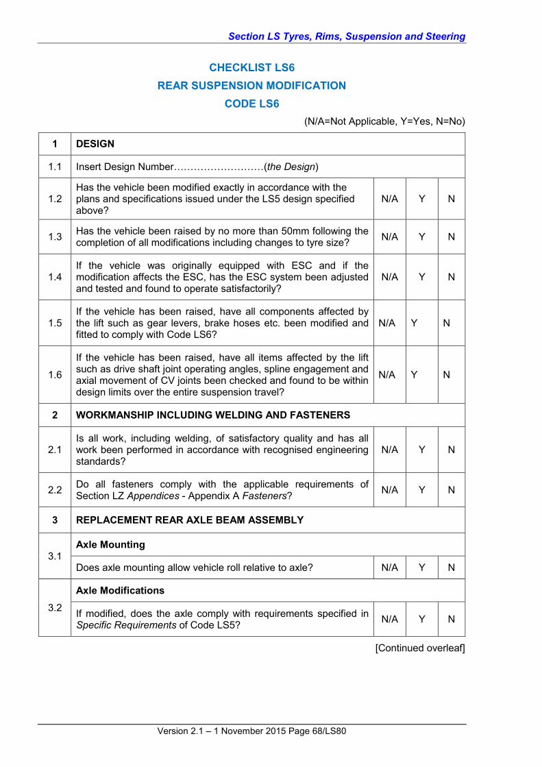
Section LS Tyres, Rims, Suspension and Steering
Version 2.1 – 1 November 2015 Page 68/LS80
CHECKLIST LS6 REAR SUSPENSION MODIFICATION
CODE LS6 (N/A=Not Applicable, Y=Yes, N=No)
1 DESIGN
1.1 Insert Design Number………………………(the Design)
1.2 Has the vehicle been modified exactly in accordance with the plans and specifications issued under the LS5 design specified above?
N/A Y N
1.3 Has the vehicle been raised by no more than 50mm following the completion of all modifications including changes to tyre size? N/A Y N
1.4 If the vehicle was originally equipped with ESC and if the modification affects the ESC, has the ESC system been adjusted and tested and found to operate satisfactorily?
N/A Y N
1.5 If the vehicle has been raised, have all components affected by the lift such as gear levers, brake hoses etc. been modified and fitted to comply with Code LS6?
N/A Y N
1.6
If the vehicle has been raised, have all items affected by the lift such as drive shaft joint operating angles, spline engagement and axial movement of CV joints been checked and found to be within design limits over the entire suspension travel?
N/A Y N
2 WORKMANSHIP INCLUDING WELDING AND FASTENERS
2.1 Is all work, including welding, of satisfactory quality and has all work been performed in accordance with recognised engineering standards?
N/A Y N
2.2 Do all fasteners comply with the applicable requirements of Section LZ Appendices - Appendix A Fasteners? N/A Y N
3 REPLACEMENT REAR AXLE BEAM ASSEMBLY
3.1 Axle Mounting
Does axle mounting allow vehicle roll relative to axle? N/A Y N
3.2
Axle Modifications
If modified, does the axle comply with requirements specified in Specific Requirements of Code LS5? N/A Y N
[Continued overleaf]

Section LS Tyres, Rims, Suspension and Steering
Version 2.1 – 1 November 2015 Page 69/LS80
(N/A=Not Applicable, Y=Yes, N=No)
4 SUSPENSION
4.1
Cross-member Mounting
Are cross-members mounted in accordance with the Design? N/A Y N
Has the chassis rail been reinforced and fitted with steel sleeves? N/A Y N
4.2 Ball Joints and Tie-rod Ends
Are all ball joint tapers compatible or modified in accordance with the Design requirements? N/A Y N
4.3 Wheel Alignment
Have all wheels been aligned in accordance with the Design specifications? N/A Y N
Note: If the answer to any question is N (No), the modification cannot be certified under Code LS6
CERTIFICATION DETAILS
Make Model Year of Manufacture
VIN
Chassis Number (If applicable)
Brief Description of Modification/s
Vehicle Modified By
Certificate Number (If applicable)
Vehicle Certified By (Print)
Signatory’s Employer (If applicable)
Signatory’s Signature Date

Section LS Tyres, Rims, Suspension and Steering
Version 2.1 – 1 November 2015 Page 70/LS80
HIGH LIFT - 50mm to 150mm (DESIGN) CODE LS7
SCOPE Code LS7 provides for the preparation of designs that may be approved by Registration Authorities for use by other signatories or modifiers. The designs under Code LS7 cover the design of vehicle lifts in excess of 50mm but not more than 150mm.
Code LS7 does not apply to ADR category L-group vehicles and motor cycles.
DESIGNS COVERED BY CODE LS7 The following is a summary of the designs that may be prepared under Code LS7:
Design of modifications that combined result in the vehicle body being raised by more than 50mm but less than 150mm from the original as manufactured height;
Design of front suspension modifications using different struts or uprights;
Design of independent rear suspension modifications using different struts, trailing arms or uprights;
Design of a conversion using a complete suspension assembly from a different vehicle model;
Design of a complete rear suspension assembly using components from different vehicle model(s); and
Alternative wheel and tyre specifications for vehicles with modified axles or suspension.
DESIGNS NOT COVERED BY CODE LS7 Designs that are not covered under Code LS7 are listed below:
Design for vehicles originally equipped with ESC that have not been approved by the vehicle manufacturer or proven through testing;
Certification of the actual physical modification of particular vehicles (this is covered by Code LS8);
Design for modifications that raise the vehicle body more than 150mm from the original as manufactured height (lifting vehicles beyond 150mm is outside of the scope of VSB 14); and
Design for modifications that raise the vehicle body more than 50mm from the original as manufactured height on vehicles that have had the wheel track reduced from the as manufactured width. Modifications to these vehicles will only be considered on an individual application basis.
COMPLIANCE WITH APPLICABLE VEHICLE STANDARDS. Modified vehicles must continue to comply with the ADRs to which they were originally constructed, except as allowed for in the AVSR. These modified vehicles must also comply with the applicable in-service requirements of the AVSR. This is not an exhaustive list and other modifications may also affect ADR compliance.
Modified pre-ADR vehicles must continue to comply with the AVSR.
Compliance with the AVSR also means compliance with the equivalent regulations of a State or Territory of Australia.
Outlined below in Table LS8 are areas of the vehicle that may be affected by the modifications and that may require re-certification, testing and/or data to show compliance for the modified vehicle.

Section LS Tyres, Rims, Suspension and Steering
Version 2.1 – 1 November 2015 Page 71/LS80
Table LS8 Summary of items that if modified, may detrimentally affect compliance with applicable ADRs
DETAIL REQUIREMENTS
Installation of Lighting ADR 13/…,
Braking System ADR 7, 7/…, 31, 31/…, 35x, 35/…
Speedometer ADR 18x. 18/…
Tyre Speed Rating ADR 24x, 24/…
Ground Clearance ADR 43/…
To determine the ADRs that apply to the vehicle in question, refer to the applicability tables in Section LO. Vehicles manufactured on or after 1 January 1969 and prior to 1 July 1988 need to comply with the Second Edition ADRs whilst vehicles manufactured after this date need to comply with the Third Edition ADRs. Section LO has separate applicability tables for each edition.
Alternatively, ADR applicability tables for individual vehicle categories may be referenced on the Department of Infrastructure and Transport RVCS website at the following address and under the section titled ADR Applicability Tables:
http://rvcs.dotars.gov.au/ The ADRs apply according to the vehicle’s category and date of manufacture. It is the responsibility of the signatory to refer to the appropriate ADR applicable to the vehicle.
SPECIFIC REQUIREMENTS 1 BODY LIFTS BETWEEN 50MM AND 150MM The following requirements must be met for all vehicle body high lift modifications. Where a modification involves a change to the suspension system design, the basic functional requirements for suspension modifications/conversions are provided as a guide to suitably qualified and experienced signatories when designing or certifying such modifications or conversions.
The design should also comply with the general guidelines contained in sub-section 2 General Requirements, Specific Requirements in Code LS3 Front Suspension and Steering Conversion – Design and Specific Requirements in Code LS5 Rear Suspension Modification – Design.
Each design should be fully documented, with drawings, calculations, procedural details, test results, wheel alignment specifications and any other data necessary to fully describe the vehicle modifications and should have a unique design number. The design document should contain:
Details of all drawings needed to fully describe the full extent of the modification;
Details of any special modification techniques, procedures or adjustments; and
Details of any testing of components and performance (e.g. bump steer plots) with related acceptance criteria.

Section LS Tyres, Rims, Suspension and Steering
Version 2.1 – 1 November 2015 Page 72/LS80
2 SUSPENSION MODIFICATIONS The available suspension travel in either direction must remain at least equivalent to two thirds of that originally available prior to modifying the system.
The available suspension rebound following the addition of increased length coil springs and longer travel shock absorbers must be at least equivalent to two thirds of the original rebound travel.
The rebound must be limited by either the shock absorber maximum travel (providing the component is designed for this type of loading), the technique used by the original manufacturer’s design or by the addition of adequately sized straps.
At full rebound the coil springs must still be securely attached to the vehicle by not having reached their free length.
All linkages and brake lines etc. must be adequately designed for the increased movement.
The maximum increase in vehicle height due to suspension modifications alone is limited to 75mm.
3 BODY BLOCKS Body blocks between the vehicle body and the chassis must comply with the following:
The material must be of similar strength and durability as the original components;
All assemblies and piping that spans between the body and the chassis must be suitable for the increased distance; and
The increase in height due to body block modifications alone is limited to 50mm.
4 WHEELS AND TYRES The overall tyre diameter can be increased to allow an increase of 7.5mm in vehicle height for passenger vehicles and no more than 25mm in vehicle height for four wheel drive vehicles (typically MC ADR category).
Tyres fitted to off-road passenger and light goods vehicles (MC, NA, NB ADR category) must not be more than 50% wider than the vehicle manufacturer’s widest optional tyre. Tyres fitted to passenger vehicles must not be more than 30% wider than the vehicle manufacturer’s widest optional tyre.
The rim width must match the recommendations for the tyre fitted.
The tables of original tyres with the maximum allowable tyre and rim sizes in Clause 4.2 Non-Standard Tyres and Rims are applicable.
The wheel track of off-road and four wheel drive vehicles (MC, NA, NB ADR category) must not be increased by more than 50mm beyond the maximum specified by the vehicle manufacturer for the particular model. The wheel track of passenger vehicles, including four wheel drives or all wheel drive vehicles certified as MA ADR category must not be increased by more than 25mm beyond the maximum specified by the vehicle manufacturer for the particular model.
The wheels must be contained within the bodywork or mudguards (including flares) when the wheels are in the straight-ahead position. Adequate clearance must be available between the tyres and the vehicle bodywork.
Speedometer accuracy must be maintained for the selected tyre and rim combination to within the degree of accuracy specified in ADR 18 where applicable.

Section LS Tyres, Rims, Suspension and Steering
Version 2.1 – 1 November 2015 Page 73/LS80
5 BRAKES Modifications to any of the brake circuitry should meet the requirements of Section LG Brakes.
The braking performance of the vehicle should also meet the requirements of Section LG Brakes.
6 VEHICLE DYNAMICS These modifications, where the centre of mass (centre of gravity) of an existing vehicle is increased, can have a significant influence on the cornering/swerving characteristics of the completed vehicle. The height that a particular vehicle can be raised is governed by the ability to safely negotiate and fully comply with the Lane Change Test as outlined in Section LT Test Procedures (Code LT2). Lane change tests are required for vehicles that have been raised by more than 50mm.
While Code LS7 allows for an overall vehicle height increase of 150mm maximum, this will be limited by the vehicle’s ability to safely negotiate the lane change test as mentioned above.
7 VEHICLE LIGHTING The dipped beam headlights must comply with the ADR requirements with respect to position and illuminated pattern. For vehicles complying with ADR 13/00 the top of the headlamp lens must not be greater than 1200mm from the ground when measured on a level surface.
8 MUDGUARDS After all modifications are completed the mudguards must continue to comply with the provisions of ADR 42.
9 COMPONENTS Both general and specific requirements specified in earlier codes in this Section that are applicable to individual steering and suspension components continue to apply. Important items such as spline engagement, operating angles of drive shaft joints and in the case of CV joints, the range of axial movement, must remain within design limits for the full range of suspension travel. Also other components such as gear levers, brake hoses etc. may need to be extended depending on the nature of the lift.
Steering linkages must continue to operate efficiently and sufficient spline contact surface must be retained for the full range of suspension travel to ensure the safe operation of the vehicle. Otherwise an appropriate steering shaft extension must be used.
Following the completion of modifications the vehicle attitude must remain as per original specifications – i.e. the original relationship between the front and rear suspension heights must not be changed and therefore the front and rear suspensions must be both raised by the same amount.

Section LS Tyres, Rims, Suspension and Steering
Version 2.1 – 1 November 2015 Page 74/LS80
CHECKLIST LS7 HIGH LIFT - 50mm to 150mm (DESIGN)
CODE LS7 (N/A=Not Applicable, Y=Yes, N=No)
1 SUSPENSION MODIFICATIONS
1.1
Front Suspension and Steering
Do the front suspension system modifications comply with all of the relevant requirements of Code LS3? N/A Y N
1.2
Rear Suspension
Do the rear suspension system modifications comply with all of the relevant requirements of Code LS5? N/A Y N
1.3
Suspension travel
Is the designed suspension travel at least two thirds of the original in all directions? N/A Y N
Has adequate rebound limiting been provided? N/A Y N
At full rebound do the coil springs remain securely attached to the vehicle by not having reached their free length? N/A Y N
Have all linkages and brake lines been designed to accommodate the increased suspension travel? N/A Y N
2 BODY BLOCKS
2.1
Mounting
Are the replacement body blocks suitably designed to carry the load as per the vehicle’s GVM? N/A Y N
When fitted, will the blocks lift the body 50mm or less? N/A Y N
[Continued overleaf]

Section LS Tyres, Rims, Suspension and Steering
Version 2.1 – 1 November 2015 Page 75/LS80
(N/A=Not Applicable, Y=Yes, N=No)
2.2
Design
Are all assemblies spanning the body and chassis suitably designed to allow for the increased distance? N/A Y N
Are the body lift blocks suitably braced to the chassis or bodywork so as to prevent excess bending loads being placed on components?
Y N
3 WHEELS AND TYRES
3.1
Tyres and Rims
Are all selected tyres and rims in accordance with Section LS? N/A Y N
Is the increase in overall diameter less than 50mm for 4 wheel drive vehicles or 15mm for passenger vehicles? N/A Y N
3.2 Speedometer
Has the speedometer accuracy been taken into account? N/A Y N
4 VEHICLE DYNAMICS
4.1
Lane Change Test (Code LT2)
Has a vehicle undergone and passed a Lane Change Test as required by Code LT2?
Y N
Was the driver satisfied that the vehicle was safe to drive? Y N
5 HIGH LIFT
5.1
Maximum Increase in Vehicle Height
Is the design total increase in vehicle height less than 150mm? Y N
Is the design top of the dipped beam headlight height less than 1200mm?
Y N
Will the dipped beam headlight pattern and position comply? Y N
5.2 Will the mudguards still continue to comply with ADR 42? Y N
6 BRAKES
6.1 Do the intended brake modifications comply with Section LG? N/A Y N
6.2 Will the brakes meet the Section LG performance requirements? N/A Y N
[Continued overleaf]

Section LS Tyres, Rims, Suspension and Steering
Version 2.1 – 1 November 2015 Page 76/LS80
(N/A=Not Applicable, Y=Yes, N=No)
7 FASTENERS
7.1 Are high tensile bolts specified for all new critical mountings? Y N
7.2 Are self-locking nuts specified for all new critical mountings? Y N
7.3 Do all fasteners specified comply with the applicable requirements of Section LZ Appendices - Appendix A Fasteners? Y N
9 DESIGN
9.1 Does the design of the modification comply with all of the requirements outlined in Code LS7? Y N
9.2
Has all work, including welding, that has been specified in the certification of the LS7 design, been determined in accordance with recognised engineering standards and the relevant Appendices of Section LZ Appendices?
Y N
9.3 Have all components affected by the lift such as gear levers, brake hoses etc. been modified to comply with Code LS7? N/A Y N
9.4
Have all items affected by the lift such as drive shaft joint operating angles, spline engagement and axial movement of CV joints been checked or designed to be within design limits over the entire suspension travel?
N/A Y N
9.5 If the vehicle was originally equipped with ESC, and if the modification affects the ESC, has the ESC system been adjusted and tested and found to operate satisfactorily?
N/A Y N
Note: If the answer to any question is N (No), the design cannot be certified under Code LS7.
CERTIFICATION DETAILS
Make Model Year of Manufacture
VIN
Chassis Number (If applicable)
Brief Description of Modification/s
Vehicle Modified By
Certificate Number (If applicable)
Vehicle Certified By (Print)
Signatory’s Employer (If applicable)
Signatory’s Signature Date
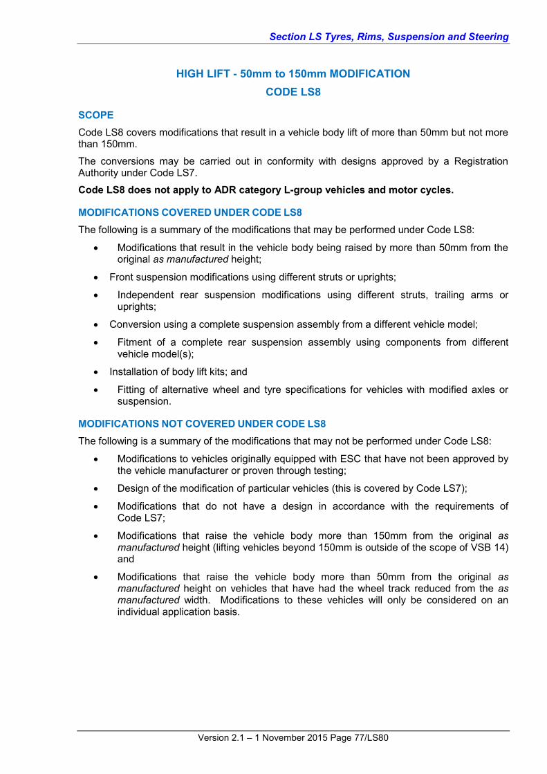
Section LS Tyres, Rims, Suspension and Steering
Version 2.1 – 1 November 2015 Page 77/LS80
HIGH LIFT - 50mm to 150mm MODIFICATION CODE LS8
SCOPE Code LS8 covers modifications that result in a vehicle body lift of more than 50mm but not more than 150mm.
The conversions may be carried out in conformity with designs approved by a Registration Authority under Code LS7.
Code LS8 does not apply to ADR category L-group vehicles and motor cycles.
MODIFICATIONS COVERED UNDER CODE LS8 The following is a summary of the modifications that may be performed under Code LS8:
Modifications that result in the vehicle body being raised by more than 50mm from the original as manufactured height;
Front suspension modifications using different struts or uprights;
Independent rear suspension modifications using different struts, trailing arms or uprights;
Conversion using a complete suspension assembly from a different vehicle model;
Fitment of a complete rear suspension assembly using components from different vehicle model(s);
Installation of body lift kits; and
Fitting of alternative wheel and tyre specifications for vehicles with modified axles or suspension.
MODIFICATIONS NOT COVERED UNDER CODE LS8 The following is a summary of the modifications that may not be performed under Code LS8:
Modifications to vehicles originally equipped with ESC that have not been approved by the vehicle manufacturer or proven through testing;
Design of the modification of particular vehicles (this is covered by Code LS7);
Modifications that do not have a design in accordance with the requirements of Code LS7;
Modifications that raise the vehicle body more than 150mm from the original as manufactured height (lifting vehicles beyond 150mm is outside of the scope of VSB 14) and
Modifications that raise the vehicle body more than 50mm from the original as manufactured height on vehicles that have had the wheel track reduced from the as manufactured width. Modifications to these vehicles will only be considered on an individual application basis.

Section LS Tyres, Rims, Suspension and Steering
Version 2.1 – 1 November 2015 Page 78/LS80
CHECKLIST LS8 HIGH LIFT - 50mm to 150mm MODIFICATION
CODE LS8 (N/A=Not Applicable, Y=Yes, N=No)
1 DESIGN
1.1 Insert Design Number………………………( the Design)
1.2 Has the vehicle been modified exactly in accordance with the plans and specifications issued under the LS7 Design Number given above?
N/A Y N
1.3 If the vehicle was originally equipped with ESC, and if the modification affects the ESC, has the ESC system been adjusted and tested and found to operate satisfactorily?
N/A Y N
2 VEHICLE CONDITION PRIOR TO MODIFICATION
2.1 Is the front suspension serviceable? Y N
2.2 Is the steering box serviceable? Y N
2.3 Is the steering linkage serviceable? Y N
2.4 Is the chassis serviceable? Y N
3 WORKMANSHIP
3.1 Is all work, including welding, of satisfactory quality and has all work been performed in accordance with recognised engineering standards?
N/A Y N
3.2 Do all new or replaced fasteners comply with the applicable requirements of Section LZ Appendices, Appendix A Fasteners? Y N
3.3 Are high tensile bolts and self-locking nuts used on all critical joints and mountings? Y N
4 MODIFICATION DETAILS
4.1 What was the original height of the vehicle body prior to any modification?
________________
4.2 What is the height of the vehicle body following completion of all lift modifications
________________
4.3 Is the difference in height less than 150mm? Y N
[Continued overleaf]

Section LS Tyres, Rims, Suspension and Steering
Version 2.1 – 1 November 2015 Page 79/LS80
(N/A= Not Applicable, Y=Yes, N=No)
4.4 What is the maximum size tyre offered by the manufacturer for this vehicle?
________________
4.5 What size tyre has been fitted? ________________
4.6 Is the difference in diameter 50mm or less? Y N
4.7 If the vehicle body has been lifted relative to the chassis, is the overall body lift 50mm or less? Y N
4.8 If the suspension has been modified to provide an increase in vehicle body height, is this increase 75mm or less? N/A Y N
5 LANE CHANGE TEST
5.1 Has the vehicle undergone a Lane Change Test as per Code LT2? Y N
5.2 Did the vehicle pass the test satisfactorily? Y N
5.3 Was the driver satisfied that the vehicle was safe to drive? Y N
5.4 Is a copy of the lane change test results form attached as required by Code LT2? Y N
6 VEHICLE CONDITION AFTER MODIFICATION
6.1 Is the front suspension serviceable? Y N
6.2 Is the steering box serviceable? Y N
6.3 Is the steering linkage serviceable? Y N
6.4 Is the chassis serviceable? Y N
6.5 Is the dipped beam headlight height less than 1200mm? Y N
6.6 Have the headlights been adjusted? Y N
6.7 Have all brake tests been satisfactorily completed? N/A Y N
6.8 Is the combined height increase 150mm or less? Y N

Section LS Tyres, Rims, Suspension and Steering
Version 2.1 – 1 November 2015 Page 80/LS80
(N/A=Not Applicable, Y=Yes, N=No)
6.9 Do the mudguards continue to comply as with ADR 42? Y N
6.10 Have all components affected by the lift such as gear levers, brake hoses etc. been modified and fitted to comply with Code LS8?
N/A Y N
6.11
Have all items affected by the lift such as drive shaft joint operating angles, spline engagement and axial movement of CV joints been checked and found to be within design limits over the entire suspension travel?
N/A Y N
Note: If the answer to any question is N (No), the modification cannot be certified under Code LS8.
CERTIFICATION DETAILS
Make Model Year of Manufacture
VIN
Chassis Number (If applicable)
Brief Description of Modification/s
Vehicle Modified By
Certificate Number (If applicable)
Vehicle Certified By (Print)
Signatory’s Employer (If applicable)
Signatory’s Signature Date


