Embed Size (px)
Citation preview

GUIDELINES ON BAT AND GUIDANCE ON BEP DRAFT 29/07/04
SECTION VIGUIDANCE/GUIDELINES BY SOURCE CATEGORY:
ANNEX C PART III SOURCE CATEGORY
A . O P E N B U R N I N G O F W A S T E
1 General Guidance
For people in many parts of the world, open burning is the cheapest, easiest, most sanitary means of volume reduction and disposal of combustible materials. This is especially true for people with no access to organized waste handling who have been left to their own devices for materials disposal. And yet, open burning is an environmentally detrimental process that generates by-product POPs and numerous other pollutant products of incomplete combustion.
Open burning of waste, including burning of landfill sites for volume reduction, is listed as an inadvertent source of by-product POPs in Annex C, Part III. Most importantly, Annex C, Part V(f) refers aspirationally to “…the aim of cessation of open and other uncontrolled burning of wastes, including the burning of landfill sites.”
In principle, open burning should simply be prohibited; however, there are practical considerations that speak to the wisdom of defining guidance for open burning with the proviso that it be minimized and eliminated as soon as and wherever feasible. Those considerations include lack of alternative disposal or recovery methods due to nonexistent or inaccessible infrastructure. In addition, sporadic open burning may be necessary for sanitary disposal of unusual material, to control disease or pests, or in the case of disaster or other emergency.1
Although the Stockholm Convention is concerned with POPs such as polychlorinated dibenzodioxins and furans (PCDD/F), HCB and PCBs as products of incomplete combustion, open burning is responsible for generation of toxic byproducts of combustion well beyond the named chemicals. Other byproducts include polycyclic aromatic hydrocarbons, particulate matter, benzene and carbon monoxide. Regardless of specific chemistry, smoke and unpleasant odors always accompany open burning, and are at best a nuisance and at worst a health hazard. Elimination of the Stockholm POPs would not sufficiently improve the emissions from open burning so as to make it an environmentally preferred means of waste disposal. It is imperative that the focus of implementation of the Stockholm Convention be on establishing alternatives to open burning rather than simply trying to improve a bad practice. In no way should provision of this guidance be construed as acceptance or justification.
Efforts to reduce open burning must focus on government, private sector and civil society support of alternative end-of-life and waste management options. Government agencies in charge of public health policy and education should be as deeply involved as those responsible for waste policy. The Basel Convention Technical Guidelines offer basic guidance on alternatives to open burning and how to implement them.2 Countries should work diligently to establish and implement sound practices including resource use reduction, reuse, recycling, composting, modern sanitary landfilling, and BAT incineration. Convention implementation efforts and the convention financial mechanism could be used to support the establishment of model waste management systems as alternatives to open burning.
In this part of the guidance, a number of specific types of open burning are considered in generic categories, typically because means of POPs mitigation in each category are similar.3 Accidental fires and intentional combustion of non-waste materials are not considered; however, they may also be sources of POPs. Parties to the convention are urged to take steps to reduce accidental biomass burning of all types as well as accidental fires in residences,
136

GUIDELINES ON BAT AND GUIDANCE ON BEP DRAFT 29/07/04
automobiles, and places of business. Parties may wish to consider restrictions on fireworks or other recreational open combustion as well.
1.1 General Process Considerations
1.1.1 Burning Process
Harmful emissions result from incomplete combustion. In the short term, where there are not realistic means to eliminate all open burning, practical process modifications that are likely to improve safety and reduce unintentional POPs generation include:4
Reduction in the amount of material discarded via open burning. Consistent with the convention, and its goal of elimination, this is the first line of improvement.
Removal of non-combustibles, including glass and bulk metals, and materials of low fuel value.
Removal of potential explosives (e.g. aerosol cans, partially full containers of flammable liquids).
Removal of hazardous materials, especially those which should be destroyed under BAT described in other parts of the guidance
Supply of sufficient air Steady burning or rate of mass loss Minimization of smoldering, possibly with direct extinguishment Small, actively turned, well-ventilated fires, rather than large poorly-ventilated dumps or
containersAnd with respect to the materials burned:
Dry, not wet, waste combustibles of high fuel value “Homogeneous” or well-blended combustibles Low density; e.g. non-compacted waste
Lower-probability techniques that may provide some reduction of PCDD/PCDF include:
Burning material in open piles rather than confined in burners Avoiding burning waste that is exceptionally high in chloride content, noting that there is
no apparent difference between inorganic chloride (salt) and organic chloride (PVC). Avoiding burning waste that contains metals such as copper and iron, even in small
amounts.1.1.2 Handling After burning
Before burned waste can be handled or covered, it must be completely extinguished. Failure to do this can potentially ignite uncontrolled burning over large areas and or allow ongoing smoldering which is shown to be the most polluting time in the life of a fire.
1.1.3 Health and safety considerations
In addition to the aforementioned guidance steps should be taken to mitigate exposure routes to dioxins and furans. As is widely recognized, most human exposure comes through the food chain. Thus, necessary burning sites should be located away from the population and from production of plants and animals for food. Ash from the process should be kept from forage areas. It is also good practice to locate combustion sites remote from or downwind of residential areas.
In addition to isolating citizens from the odor, nuisance and potential toxics exposure of open burning, in all cases whether in a landfill or at a secluded facility, personnel tending the fires should position themselves upwind from any burning waste and be clear of the burning waste. Protective clothing such as gloves, boots, and overalls together with smoke masks and goggles may be advisable, especially for larger fires.
136
GUIDELINES ON BAT AND GUIDANCE ON BEP DRAFT 29/07/04
1.1.4 Intermediate Technologies
Devices known as “incinerators” are sold for the purpose of burning refuse. In some cases these devices may be as simple as steel drums or barrels which contain the waste but do not constitute BAT incineration. For the purposes of this guidance, we view “open burning” as any form of combustion for waste disposal that does not meet the standards for BAT incineration of municipal, medical or hazardous waste, as defined by a party. In general, good incineration involves a combination of appropriate residence time in the flame zone, combustion gases reaching an elevated temperature of at least 800º C, in the presence of sufficient turbulence to avoid unburned material. In addition, BAT combustion will usually involve post-treatment of combustion gases to minimize the time that products of combustion spend in the temperature conditions conducive to formation of PCDD/F (ca. 250-450º C).
1.2 Other Considerations and Opportunities for Further Refinement of Methods
Research in open burning is hampered by irreproducibility of experiments, experimental scale (as in landfill fires) and control experimental conditions. On the other hand, these kinds of difficult to reproduce conditions are the hallmarks of open burning as actually practiced. Further research may define more precisely the impact of variables on the open burning process and allow development of better interim techniques for temporary use on the way to total elimination. For example, there may be processes that are analogous to those used for POPs reduction in controlled combustion.5
2 Intentional Biomass Burning
2.1 Agricultural/Crop Residue; Land Clearing Debris
2.1.1 Material Composition
In general, biomass: wood, grass, other vegetation. Depending on locality may include sisal, coffee husks, corn/maize cobs and stalks, sugarcane bagasse and rice husks, among others. This material may be composed of living plants, deadfalls or plant material that has been cut and dried. Intentional burning does not constitute well-controlled combustion although the geographical boundaries to be burned may be well defined.
Biomass materials will vary in water content (live vs. harvested material; wet vs. dry season; low vs. high humidity), fuel density (mass per hectare and degree of compaction or other measure) and species. Biomass materials vary naturally in chloride content6,7 and may have been treated with chemicals (chlorinated pesticides or fertilizers), metals capable of catalyzing POPs formation (copper, for example as copper chromium arsenate treated wood) or inhibitors (sulfur, nitrogen containing materials), all of which may adversely impact POPs generation during uncontrolled combustion.8,9
2.1.2 Barriers to Elimination; Remedies or Policy to Remove Barriers
Prescribed burning may be permitted by government for perceived economic benefit (cost reduction), perceived agricultural benefit (ash as soil adjuvant), termite, reptile or other pest control, convenience, or recreation. In each of these cases the government has the power to remove permission for such burning and to educate the public regarding the detrimental nature of open burning, especially if it is conducted on a large scale. In some cases, as for termite control, open burning of biomass may be the least environmentally problematic approach. Cost and availability of alternative means of disposal or environmental management can be an overarching issue.
2.1.3 Strategies and Policy Instruments to Avoid, Reduce or Divert Waste
Where possible, machine harvesting paired with alternative, non-destructive uses for harvested materials can reduce the need for wholesale burning. In areas of livestock cultivation materials may be harvested for silage. Grass may be dried for hay; other crop waste may be processed for fodder, fermented, allowed to decompose in situ or composted; wood of quality may be harvested for timber; yard waste can be composted and utilized as soil amendment; some nontraditional biomass can be used as a raw material for paper. In most cases, these alternatives also require markets and infrastructure.
136

GUIDELINES ON BAT AND GUIDANCE ON BEP DRAFT 29/07/04
For agriculture, “Zero-Burning” techniques as outlined by ASEAN should be applied where applicable to the region and the crops.10 Reduction and elimination of POPs from open burning may provide an opportunity to reform agricultural practices.
2.1.4 Alternatives, Barriers to Use and Policy Instruments to Remove Barriers
Alternatives vary by situation. Barriers include lack of education, lack of government will to reduce dependence upon open burning to accomplish goals, and lack of alternative machinery or processes where open burning is an integral part of local agriculture. Cost of alternatives in any form may be a barrier, and as with any reforms, economic instruments may be necessary or desirable to induce change. Demonstration projects and research in the regions may help understanding of feasibility of alternatives.
2.1.5 Burning Techniques and Attributes, and Means of Improvement
Where open burning of biomass is permitted by government policy the process improvements noted in the general guidance should be implemented. Careful planning of prescribed burns modulated by weather conditions will allow greater control and less exposure of population to smoke downstream. After the fires, ash management may be an issue.
Application of chemicals in agriculture and forestry should be minimized consistent with local needs and good management. Where mechanical clearing and alternative use of harvested material is possible, incidental burns can be avoided; however, in certain local situations prescribed small burns may have a place in an overall land management scheme if used to prevent more devastating inadvertent burning.
Recognizing that control of prescribed burns can be lost, fire abatement procedures (training, equipment, planning), infrastructure (access, roads), and management planning are all reasonable secondary support measures.
3 Open Burning of Mixed Consumer Waste
3.1 Household Waste, Landfill/Dump Fires; Industrial Non-hazardous Waste
3.1.1 Material Composition
Household waste and the composition of landfills and dumps may be qualitatively very similar. They differ importantly where modulated by programs (such as recycling, scavenging, composting or other segregation) which remove specific streams from waste between household and repository. Industrial non-hazardous waste may arise from commercial establishments such as shops, restaurants and light manufacturing. It will differ according to the exact commercial source but may contain many of the same materials as found in household waste.
Open burning of waste has been the topic of significant study.8 There seems to be very little data regarding dump fires and POPs.3
Waste composition studies show variation in waste among countries and especially between developed and developing countries. In developing countries as much as 50% of waste composition may be putrescibles such as kitchen waste. In developed countries, more convenience packaging and electronics may be found unless these materials have been removed by other end-of-life systems. Significant differences also may exist between urban and rural waste and among wastes from different regions, regardless of development. In general, household waste streams, and landfill waste will contain paper, plastic, organics such as food refuse, glass, metal, wood, leather and miscellaneous other materials. Under poorly controlled conditions, household hazardous waste such as cleaners, paints and solvents may find its way into a non-hazardous-rated landfill or dump.
Management approaches will change the composition and performance of a landfill/dump. In a modern, compartmentalized landfill, daily cover consisting of soil or clay will be added to the refuse. A traditional dump, by comparison, is far less well-organized.
Compartmentalization, addition of inert materials (daily cover), and compaction, over time, reduces the moisture content of the landfill but also the likelihood of spontaneous ignition. Traditional dumps are more likely to burn.
136

GUIDELINES ON BAT AND GUIDANCE ON BEP DRAFT 29/07/04
All disposal sites will generate some combustible gas (e.g., methane) from anaerobic degradation of organic materials contained within. Unless this gas is controlled it constitutes a highly combustible fuel for either spontaneous or illicit anthropogenic ignition. It is also a potent “greenhouse gas.”
3.1.2 Barriers to Elimination; Remedies or Policy to Remove Barriers
Household waste will be burned in the open where cost, convenience or local custom/social acceptability make that option attractive to citizens or groups of citizens. The preferred combustion alternative is BAT incineration with energy recovery, however combustors run the gamut from BAT incineration through a continuum of decreasing technology and efficiency to open pile or pit or “barrel” burning. In cases where people live far outside municipal governance, solutions to waste disposal will undoubtedly be ad hoc. Without appropriate systems they will be ad hoc even within municipal governance.
In order to eliminate open burning, reasonable alternatives must exist and the public must be educated regarding their availability as well as the harm of open burning.
At-source or centralized collection, recycling or other disposal must be affordable and effective. Landfills must be designed and operated according to modern standards.11 Government must accept responsibility to create waste reclamation/disposal systems as a public utility/service. Countries and municipalities must then have the will to mandate an end to garbage burning and accept the responsibility for enforcement of those laws. Additionally, where modern landfill is an option, waste management plans and regulations must include provisions for siting new landfills so as to maintain disposal capacity.
Simply accepting the responsibility for providing waste management systems may not in itself mean the end of open burning. Garbage could be collected and deposited in landfills or dumps, which can themselves be sites for open burning. Policies and practices must be developed and applied to these centralized services. Spontaneous ignition/combustion can be reduced by collection of landfill gas or regulations requiring modern landfill construction techniques along with permanent closing of obsolete dumps.
Accidental anthropogenic combustion in dumps can be reduced by prohibiting, licensing or limiting access to landfills/dumps. In many cases fires are set by scavengers living and working in these areas. Fires, accidental or intentional, can ignite discarded materials or landfill gas. Authorities must accept responsibility and enact regulations organizing scavenging activities, providing safe conditions for workers and limiting access to and overt residence on landfills.
Intentional anthropogenic combustion; that is, burning dump contents for volume reduction, must be prohibited by authorities. In order to avoid the need for dump burning sufficient planning must be given to landfill size, space, location and management and waste reduction/elimination programs so as to obviate the need.
Waste management is a system. Where the system works to make final disposal of true waste a collective responsibility rather than an individual responsibility, direct economic costs may rise, but in general environmental costs and impacts will fall.
3.1.3 Strategies and Policy Instruments to Avoid, Reduce or Divert Waste
Source Reduction. Careful study of local waste composition may lead to specific programs for reduction of large volume streams. As an example, in certain cases bulk purchase of products can reduce the need for individual product packaging. This and other strategies may be modulated by population density.
Composting. Where significant fractions of household waste will biodegrade, and where the population density will allow it, municipalities should provide education on cost- and space-effective composting. Included in this strategy is appropriate diversion of organic waste to animal feed or other similar productive use, modulated by a concern for spread of disease. Education must include means for vermin and disease vector control. Some organic wastes may contain POPs or materials that could be converted to POPs under composting conditions, and they should be treated separately in order to guarantee a high-quality, low-POPs-content compost. In some
136

GUIDELINES ON BAT AND GUIDANCE ON BEP DRAFT 29/07/04
cases, composting can be enhanced by substitution of certain biodegradable materials for alternatives.
Reuse. Where parts or entire devices can be recovered, washed, repaired or reclaimed as fabricated articles the need for disposal can be reduced. In many cases, labor involved in such reclamation/value creation can be cost-effective and an economic benefit vs. purchase of new devices.
Recycling. Many waste streams contain valuable, reclaimable items. Metals, glass, clean dry paper, corrugated board, cloth, plastics and wood are recyclable streams. Depending on situations, centralized collection and recycling infrastructure can be cost-effective. In other situations, simply providing a safe staging area at a disposal site and encouraging development of markets for recycled material can facilitate recovery by scavengers.
Incineration. In some situations BAT incineration, especially with energy recovery, and open burning may coexist. Where they do, incineration is preferable to open burning, but may not be the only alternative. Authorities must take care to understand specific local barriers to elimination of open burning in favor of less environmentally burdensome disposal including source reduction, reuse, recycling and BAT incineration. Collection and cost may be one such barrier; however, BAT incineration when coupled with energy recovery may mitigate that cost and provide significant energy benefit.
Modern Landfill. Given the differences between modern engineered landfills and unorganized dumps, modern landfill construction with collection of gas and leachate, appropriate opportunity for recycling and reuse is preferable to open burning. As noted above, authorities will need to accept that education and cost-effective waste disposal options must be provided if open burning is to be eliminated.
Modern landfills differ from dumps in many ways. As engineered constructions, they are typically safer, more sanitary and less prone to anthropogenic combustion. They also require active management and security measures to exclude unauthorized people (e.g. scavengers) and may be relatively more expensive than open burning or low-tech dumping.
Policies that prohibit disposal of hazardous industrial and infectious wastes in the normal waste stream will enhance the safety of the municipal disposal system. Governments can encourage use of alternative methods listed above by implementing legal restrictions on open burning; mandates for composting, recycling or recovery; taxes on excessive waste placed into the disposal system or institution of lower-cost and more convenient resource management systems.
3.1.4 Alternatives, Barriers to Use and Policy Instruments to Remove Barriers
Strategies for waste reduction and available alternatives to open burning are largely the same.
3.1.5 Burning Techniques and Attributes, and Means of Improvement
Where none of the previously mentioned alternatives are feasible or when alternatives cannot be implemented in a timely fashion, governments may wish to educate citizens on ways to reduce the impacts of open burning. Those process improvements have been outlined in the general guidance.
3.2 Construction/Demolition/Post-disaster Debris
3.2.1 Material Composition
Construction waste will consist of the usual materials of construction and potentially the packaging in which the materials are brought to the site (pallets, sacks, etc.). Materials of construction of buildings vary by size, type and geographic location. Types of buildings, whether commercial, office, multi-family or single-family will differ significantly between developed and developing countries and among regions. Common combustible materials of construction include wood, paper and other cellulosics, asphalt, paint and various plastics. Metal contamination of combustibles is not unknown.
Demolition waste, and particularly post-disaster debris will contain other occupant belongings. These materials also vary with the type of building, geography and development of the economy.
136

GUIDELINES ON BAT AND GUIDANCE ON BEP DRAFT 29/07/04
Partially burned remains of a fire in an industrial operation may also qualify as post-disaster debris or hazardous waste.
For dwellings, this similarity will be to household waste, and will be greater in developing countries; in developed countries, given more possessions, there will be an increase in fabric (clothes), foam (furniture), rigid plastics (appliances) and fiber (carpeting).
For commercial buildings the contents will be representative of the business and will include furnishings and fiber similar to those in dwellings as well as electronics and volumes of paper (offices) or concentrations of products for sale.
3.2.2 Barriers to Elimination; Remedies or Policy to Remove Barriers
Intentional combustion of waste derived from construction or demolition is a matter of low cost and convenience at the job site. It is done due to sanitary needs, the cost of removal, inconvenience of on-site burial or unavailability of alternatives. While it is a poor practice, and should be avoided under any but the worst circumstances regarding public health, intentional combustion of post-disaster debris is known due to unavailability of alternatives, desire to avoid massive use of landfill space or for convenience in clearing areas after earthquake.12 The issue, nominally, is cost whether expressed as direct cost or the cost of development or use of other disposal means.
3.2.3 Strategies and Policy Instruments to Avoid, Reduce or Divert Waste
Clean, uncontaminated construction waste can be collected, sorted and usable materials diverted to other construction, shredding for mulch and material recycling. Demolition, when done as disassembly can yield many fixtures suitable for resale and reuse. Materials from demolition which cannot be reused or reprocessed can be separated and disposed, much as construction waste.
While in theory the strategies used for treatment of construction and demolition waste can also be used for post-disaster debris, the scale can be enormously different. After a disaster there may be no choice but to move material to a landfill site, allow scavenging as usual or conduct recovery operations there. Landfilling without scavenging or BAT incineration may be the best option in emergency, depending on exact circumstances.
Governments can--and some do--prohibit open burning of construction and demolition debris. Where there is poor waste management infrastructure, many of the same instruments used in recovery of household waste may be useful for construction and demolition materials.
3.2.4 Alternatives, Barriers to Use and Policy Instruments to Remove Barriers
As outlined above, the alternatives for waste disposal on construction and demolition sites are collection, separation, disassembly, resale, reuse and recycling. These processes can be economically viable or can be made economically viable by changes in laws or regulations governing disposal of these materials. Such instruments include bans on open burning, taxes on landfill disposal of construction and demolition material or economic instruments promoting recycling. In many cases, the resale of building fixtures is already economically viable; this is particularly true in developing countries.
Additionally, contracts for construction can be written to specify removal of debris as a responsibility of the contractor. Acceptable means of disposal can also be specified by contract.
3.2.5 Burning Techniques and Attributes, and Means of Improvement
For these materials the same general guidance holds as outlined elsewhere in the document. Burning should be a last resort and should actively exclude materials that do not burn well or at all.
136

GUIDELINES ON BAT AND GUIDANCE ON BEP DRAFT 29/07/04
4 Open Burning of Specific Materials and Miscellaneous
4.1 Agricultural Plastic
4.1.1 Material Composition
Agricultural film is usually made from polyethylene due to cost but ethylene-vinyl acetate copolymer (EVA) is also offered for sale. PVC has been used previously, but appears not to be common today. Among other uses, agricultural film is used for covering fields in early season to warm the ground; as bale wrap, as silage, fertilizer or agricultural chemical bags and as greenhouse film. Some specialty suppliers offer material specified to be degradable.
Rigid plastic containers of pesticides or other agricultural chemicals may be found as well. Bags are usually low density polyethylene; bottles, drums and tubs are usually high density polyethylene, a multilayer polyethylene, or a polyethylene container whose interior surface has been treated to reduce interaction with the product contents. One report13 discusses experiments burning bags containing residual pesticide but finds PCDD/F only “at very low levels” versus blanks for both air emissions and solid residual. Following published procedures for rinsing containers and treating the rinse water properly will reduce this low possibility significantly.
4.1.2 Barriers to Elimination; Remedies or Policy to Remove Barriers
Material located far from normal waste collection will be discarded in the lowest cost and most convenient method. Burning could be reduced by institution of a collection scheme for the material, particularly if many farmers in an area use the same material. Governments can also institute education programs and laws prohibiting burning.
4.1.3 Strategies and Policy Instruments to Avoid, Reduce or Divert Waste
Agricultural film is recycled extensively in some countries. This is facilitated when material is collected explicitly. Where there is no opportunity for recycle, other forms of disposal are utilized, including landfill. Use of additives such as UV-inhibitors can extend the life of greenhouse films and reduce the need for disposal. Absent specific programs, material used for wrapping bales or bagging compost is discarded in the same was as any packaging in a particular area. In some areas, film can be recycled explicitly, compounded into wood-plastic composites or processed into refuse-derived fuel for combustion in a BAT incinerator. For bottles, WHO recommends triple-rinsing, then puncturing and burying them14.
4.1.4 Alternatives, Barriers to Use and Policy Instruments to Remove Barriers
Strategies for waste reduction and available alternatives to open burning are largely congruent.
4.1.5 Burning Techniques and Attributes, and Means of Improvement
Agricultural film, while combustible, because of the way it has been manufactured will tend to melt and shrink. Good burning could depend on shredding to increase surface-to-volume ratio or relatively slow feeding of material. High temperature, well-ventilated combustion is possible, but may be challenging on a large scale if film is the only material burned.
Bottles may not burn well due to their surface-to-mass ratio even if dry and combustible. Alternative fuel may be required and should be material consistent with good open burning as described in the general guidance.
4.2 Tires
4.2.1 Material Composition
Tires are a composite of styrene-butadiene copolymer or natural rubber, polyamide, steel wire, carbon black and numerous other organic and inorganic additives. Tires are relatively high in sulfur as a result of vulcanization. Sulfur inhibits POPs formation in combustion; the probability for generation of chlorinated POPs in this waste is probably lower than for mixed waste; however, poor combustion of large volumes of tires in open burning situations may be a prodigious generator of other hazardous organic pollutants including SO2 and PAHs.
136

GUIDELINES ON BAT AND GUIDANCE ON BEP DRAFT 29/07/04
4.2.2 Barriers to Elimination; Remedies or Policy to Remove Barriers
Ignition of tire fires can be natural (lightning) or anthropogenic. Tire dumps present a number of hazards including culture of insect disease vectors. Additionally, they occupy large spaces. Anthropogenic burning of tires can and has been undertaken to alleviate either of these problems.
4.2.3 Strategies and Policy Instruments to Avoid, Reduce or Divert Waste
Worn tires can be retreaded and reused in many cases. Modern technology has extended the life of the average tire by a factor of ten over the past thirty years. Utilizing tires with longest life minimizes need for disposal. Alternatively they may be recycled to various uses, either whole or as shredded material. Whole, or preferably shredded tires can be landfilled. However, whole tires and similar articles like uncrushed bottles may tend to “float” to the surface of a dump. Collection of tires in above-ground dumps constitutes an eyesore and a hazard for insect control and potential for uncontrolled combustion.
4.2.4 Alternatives, Barriers to Use and Policy Instruments to Remove Barriers
Efficient combustion of shredded tires has been demonstrated in cement kilns; coal and waste wood combustors can also burn shredded tires efficiently and safely if done under good combustion and emission control conditions. Waste tires may be reprocessed and used as a component of road surfacing materials. Additionally, tires may be pressed into service for fencing, reef creation or soil erosion control. Use of tires above ground, however, must take into consideration and mitigate the tendency to collect water and harbor insect infestation.
4.2.5 Burning Techniques and Attributes, and Means of Improvement
Open burning of tires is modulated by scale. An individual tire can be used to assist in combustion of wet brush. As a mass or in dumps, however, there is virtually no way in which open burning of tires can be improved; extinguishment of large-scale fires is almost impossible and they may burn for years.
4.2.6 Crude Oil/Oil Well/Oil Spills
4.2.7 Material Composition
Crude oil consists largely of carbon and hydrogen with smaller constituent amounts of oxygen, sulfur and chlorine. As found in nature, it may be contaminated with salt or salt water from drilling or if spilled on salty ground or on an ocean. Spilled oil from pipeline breaks has been burned to mitigate potential contamination of a frozen river.15
4.2.8 Barriers to Elimination; Remedies or Policy to Remove Barriers
Cost, convenience and lack of alternative recovery or disposal methods.
4.3 Strategies and Policy Instruments to Avoid, Reduce or Divert Waste
To the extent this is a waste issue and not one of recovery from accident, better procedures for handling materials may improve normal performance. In addition, biological remediation methods may be useful in some circumstances
4.4 Military Ordnance/Munitions
4.4.1 Material Composition
Among other materials, explosives such as trinitrotoluene (TNT), ammonium picrate (Explosive D), 1,3,5-triamino-2,4,6-trinitrobenzene (TATB), 1,1-dimethylhydrazine (UDMH). In specialized situations chemical and biological weapons may also be found.
4.4.2 Barriers to Elimination; Remedies or Policy to Remove Barriers
The actual extent of this practice is not well characterized, but it may be a matter of convenience or exigency, depending on whether the destruction is done in the midst of battle or in the disposal of obsolete materials.
136

GUIDELINES ON BAT AND GUIDANCE ON BEP DRAFT 29/07/04
4.4.3 Strategies and Policy Instruments to Avoid, Reduce or Divert Waste
Various controlled forms of combustion and chemical destruction 16,17,18 have been designed and tested. Explosives and propellants can be removed from weapons with subsequent reformulation or destruction.19 Simple detonation in a closed chamber with flue gas cleaning may be sufficient; on the other hand, sophisticated combustion or non-combustion chemical techniques may be either useful or necessary. Technology for chemical weapons destruction under the Chemical Weapons Convention has been reviewed in detail.20
5 REFERENCES
136

B . T H E F O L L O W I N G T H E R M A L P R O C E S S E S I N T H E M E T A L L U R G I C A L I N D U S T R Y < T H A T W E R E N O T M E N T I O N E D I N P A R T I I O F A N N E X C
1. SECONDARY LEAD PRODUCTION
1 Process Description
“Secondary lead smelters produce lead and lead alloys from lead-bearing scrap material. More than 60 percent of all secondary lead is derived from scrap automobile batteries. Other raw materials used in secondary lead smelting include wheel balance weights, pipe, solder, drosses, and lead sheathing.
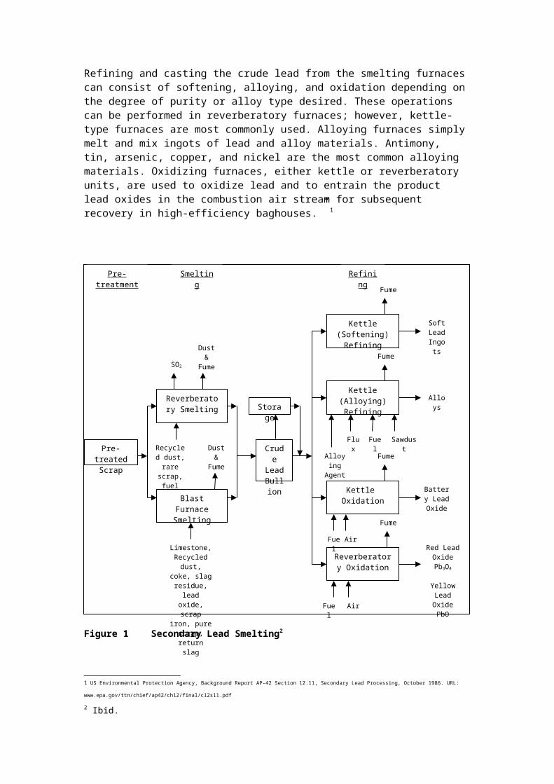
Secondary lead smelting includes 3 major operations: scrap pre-treatment, smelting, and refining. Scrap pre-treatment is the partial removal of metal and nonmetal contaminants from leadbearing scrap and residue. Processes used for scrap pre-treatment include battery breaking, crushing, and sweating. Battery breaking is the draining and crushing of batteries, followed by manual separation of the lead from nonmetallic materials. This separated lead scrap is then sweated in a gas- or oil-fired reverberatory or rotary furnace to separate lead from metals with higher melting points. Rotary furnaces are usually used to process low-lead-content scrap and residue, while reverberatory furnaces are used to process high-lead-content scrap. The partially purified lead is periodically tapped from these furnaces for further processing in smelting furnaces or pot furnaces.
Smelting produces lead by melting and separating the lead from metal and non-metallic contaminants and by reducing oxides to elemental lead. Smelting is carried out in blast,reverberatory, and rotary kiln furnaces. In blast furnaces pre-treated scrap metal, rerun slag, scrap iron, coke, recycled dross, flue dust, and limestone are used as charge materials to the furnace. The process heat needed to melt the lead is produced by the reaction of the charged coke with blast air that is blown into the furnace. Some of the coke combusts to melt the charge, while the remainder reduces lead oxides to elemental lead. As the lead charge melts, limestone and iron float to the top of the molten bath and form a flux that retards oxidation of the product lead. The molten lead flows from the furnace into a holding pot at a nearly continuous rate.
Refining and casting the crude lead from the smelting furnaces can consist of softening, alloying, and oxidation depending on the degree of purity or alloy type desired. These operations can be performed in reverberatory furnaces; however, kettle-type furnaces are most commonly used. Alloying furnaces simply melt and mix ingots of lead and alloy materials. Antimony, tin, arsenic, copper, and nickel are the most common alloying materials. Oxidizing furnaces, either kettle or reverberatory units, are used to oxidize lead and to entrain the product lead oxides in the combustion air stream for subsequent recovery in high-efficiency baghouses.” 1
1 US Environmental Protection Agency, Background Report AP-42 Section 12.11, Secondary Lead Processing, October 1986. URL: www.epa.gov/ttn/chief/ap42/ch12/final/c12s11.pdf

Figure 1Secondary Lead Smelting2 2 Sources of Unintentionally Produced POPs
The formation of polychlorinated dibenzoparadioxins (PCDD) and polychlorinated dibenzofurans (PCDF) is probable due to the presence of chlorine from plastics and trace oils in the feed material.
2.1 General Information on Emissions from Secondary Lead Smelters3
Air emissions from secondary lead smelting can escape as stack or fugitive emissions depending on the facility age or technology. Main contaminants are sulphur dioxide (SO2), other sulphur compounds and acid mists, nitrogen oxides (NOx), metals, especially lead, and their compounds, dusts and PCDD/PCDF. SO2 is collected and processed into sulphuric acid in acid plants. Fugitive SO2 emissions can be controlled by good extraction and sealing of furnaces. NOx can be reduced using low NOx or oxy-fuel burners. Particulate matter is collected using high efficiency dust removal methods such as fabric filters and returned to the process.
2.2 Emissions of PCDD/PCDF to Air
PCDD/PCDF are formed during base metals smelting through incomplete combustion or by de-novo synthesis when organic and chlorine compounds such as oils and plastics are present in the feed material.
“PCDD/PCDF or their precursors may be present in some raw materials and there is a possibility of de-novo synthesis in furnaces or abatement systems. PCDD/PCDF are easily
2 Ibid.3 European Commission, Integrated Pollution Prevention and Control Reference Document on Best Available Techniques in the Non Ferrous Metals Industries, December 2001, p. 359-368.
Pre-treated Scrap
Reverberatory Smelting
Blast Furnace Smelting
Crude Lead Bullio
n
Kettle (Softening) Refining
Kettle (Alloying) Refining
Kettle Oxidation
Reverberatory Oxidation
Pre-treatment Smelting Refining
Storage
SO2
Dust &
Fume
Recycled dust, rare scrap, fuel
Dust &
Fume
Limestone, Recycled dust,
coke, slag residue, lead oxide, scrap iron, pure
scrap, return slag
Soft Lead
Ingots
Alloys
Battery Lead Oxide
Red Lead OxidePb3O4
Yellow Lead OxidePbO
Fuel Air
Fume
Fuel Air
Fume
Fume
Fume
Flux
Alloying Agent
Fuel Sawdust

adsorbed onto solid matter and may be collected by all environmental media as dust, scrubber solids and filter dust.
The presence of oils and other organic materials on scrap or other sources of carbon (partially burnt fuels and reductants, such as coke), can produce fine carbon particles which react with inorganic chlorides or organically bound chlorine in the temperature range of 250 to 500 °C to produce PCDD/PCDF. This process is known as de-novo synthesis and is catalysed by the presence of metals such as copper or iron.
Although PCDD/PCDF are destroyed at high temperature (above 850 °C) in the presence of oxygen, the process of de-novo synthesis is still possible as the gases are cooled through the “reformation window”. This window can be present in abatement systems and in cooler parts of the furnace e.g. the feed area. Care taken in the design of cooling systems to minimise the residence time in the window is practised to prevent de-novo synthesis.” 4
2.3 Releases to Other Media
Wastewater originates from process effluent, cooling water and runoff and is treated using wastewater treatment techniques. Process residues are recycled, treated using downstream methods to recover other metals, or safely disposed.3 Recommended Processes
Variation in feed material and desired product quality influences process design and configuration. These processes should be applied in combination with good process control, gas collection and abatement systems. Processes considered as BAT include the blast furnace (with good process control), the ISA Smelt/Ausmelt furnace, the Top Blown Rotary furnace, the electric furnace and the rotary furnace.5
The submerged arc electric furnace is a sealed unit for mixed copper and lead materials. It is cleaner than other processes if the gas extraction system is well designed and sized.6
“The injection of fine material via the tuyeres of a blast furnace has been successfully used and reduces the handling of dusty material and the energy involved in returning the fines to a sinter plant.” 7 This technique minimises dust emissions during charging and thus reduces the release of PCDD/PCDF through adsorption on particulate matter.
No information is available on alternate processes to smelting for secondary copper processing.
4 Primary and Secondary Measures
Primary and secondary measures of PCDD/PCDF reduction and elimination are discussed below.
4.1 Primary Measures
Primary measures are regarded as pollution prevention techniques to reduce or eliminate the generation and release of POPs. Possible measures include:
1. Pre-sorting of Feed Material :
Scrap should be sorted and pre-treated to remove organic compounds and plastics to reduce PCDD/PCDF generation from incomplete combustion or by de-novo synthesis. Whole battery feed or incomplete separation should be avoided. Feed storage, handling and pre-treatment techniques will be determined by material size distribution, contaminants and metal content.
Milling and grinding, in conjunction with pneumatic or density separation techniques, can be used to remove plastics. Oil removal can be achieved through thermal de-coating and de-
4 European Commission, Integrated Pollution Prevention and Control Reference Document on Best Available Techniques in the Non Ferrous Metals Industries, December 2001, p. 133.5 European Commission, Integrated Pollution Prevention and Control Reference Document on Best Available Techniques in the Non Ferrous Metals Industries, December 2001, p. 379.6 European Commission, Integrated Pollution Prevention and Control Reference Document on Best Available Techniques in the Non Ferrous Metals Industries, December 2001, p. 395.7 European Commission, Integrated Pollution Prevention and Control Reference Document on Best Available Techniques in the Non Ferrous Metals Industries, December 2001, p. 404.

oiling processes. Thermal de-coating and de-oiling processes for oil removal should be followed by afterburning to destroy any organic material in the off-gas.8
2. Effective Process Control :
Process control systems should be utilized to maintain process stability and operate at parameter levels that will contribute to the minimization of PCDD/PCDF generation, such as maintaining furnace temperature above 850 °C to destroy PCDD/PCDF. Ideally, PCDD/DF emissions would be monitored continuously to ensure reduced releases. Continuous emissions sampling of PCDD/PCDF has been demonstrated for some sectors (e.g., waste incineration), but research is still developing in this field. In the absence of continuous PCDD/PCDF monitoring, other variables such as temperature, residence time, gas components and fume collection damper controls should be continuously monitored and maintained to establish optimum operating conditions for the reduction of PCDD/PCDF.
“Particular attention is needed for the temperature measurement and control for furnaces and kettles used for melting the metals in this group so that fume formation is prevented or minimised.” 9
4.2 Secondary Measures
Secondary measures are pollution control techniques to contain and prevent emissions.
These methods do not prevent the formation of contaminants.
1. Fume and Gas Collection:
Fume and off-gas collection should be implemented in all stages of the smelting process to control PCDD/PCDF emissions.
“The fume collection systems used can exploit furnace-sealing systems and be designed to maintain a suitable furnace depression that avoids leaks and fugitive emissions. Systems that maintain furnace sealing or hood deployment can be used. Examples are through hood additions of material, additions via tuyeres or lances and the use of robust rotary valves on feed systems. An [efficient] fume collection system capable of targeting the fume extraction to the source and duration of any fume will consume less energy. BAT for gas and fume treatment systems are those that use cooling and heat recovery if practical before a fabric filter except when carried out as part of the production of sulphuric acid.” 10
2. High Efficiency Dust Removal :
Dusts and metal compounds generated from the smelting process should be removed. This particulate matter possesses high surface area on which PCDD/PCDF easily adsorb. Removal of these dusts would contribute to the reduction of PCDD/PCDF emissions. Techniques to be considered are the use of fabric filters, wet/dry scrubbers and ceramic filters. Collected particulate should be recycled in the furnace.
Fabric filters using high performance materials are the most effective option. Innovations regarding this method include bag burst detection systems, online cleaning methods, and catalytic coatings to destroy PCDD/PCDF. 11
3. Afterburners and quenching :
Afterburners (post-combustion) should be used at a minimum temperature of 950°C to ensure full combustion of organic compounds.12 This stage is to be followed by rapid quenching of
8 European Commission, Integrated Pollution Prevention and Control Reference Document on Best Available Techniques in the Non Ferrous Metals Industries, December 2001, p. 232.9 European Commission, Integrated Pollution Prevention and Control Reference Document on Best Available Techniques in the Non Ferrous Metals Industries, December 2001, p. 390.10 European Commission, Integrated Pollution Prevention and Control Reference Document on Best Available Techniques in the Non Ferrous Metals Industries, December 2001, p. 397.11 European Commission, Integrated Pollution Prevention and Control Reference Document on Best Available Techniques in the Non Ferrous Metals Industries, December 2001, p.139-140.

hot gases to temperatures below 250°C. Oxygen injection in the upper portion of the furnace will promote complete combustion. 13
It has been observed that PCDD/PCDF are formed in the temperature range of 250 to 500°C. These are destroyed above 850°C in the presence of oxygen. Yet, de novo synthesis is still possible as the gases are cooled through the reformation window present in abatement systems and cooler areas of the furnace. Proper operation of cooling systems to minimise reformation time should be implemented.14
4. Adsorption on Activated Carbon :
Activated carbon treatment should be considered for PCDD/PCDF removal from smelter off-gases. Activated carbon possesses large surface area on which PCDD/PCDF can be adsorbed. Off-gases can be treated with activated carbon using fixed or moving bed reactors, or injection of carbon particulate into the gas stream followed by removal as a filter dust using high efficiency dust removal systems such as fabric filters.
5 Emerging Research
Catalytic Oxidation:
Catalytic oxidation is an emerging technology used in waste incinerators to eliminate PCDD/PCDF emissions. This process should be considered by secondary base metals smelters as it has proven effective for PCDD/PCDF destruction in waste incinerators.
Catalytic oxidation processes organic compounds into water, carbon dioxide (CO2) and hydrochloric acid using a precious metal catalyst to increase the rate of reaction at 370 to 450°C. In comparison, incineration occurs typically at 980°C. Catalytic oxidation has been shown to destroy PCDD/PCDF with shorter residence times, lower energy consumption and 99% efficiency, and should be considered. Off-gases should be de-dusted prior to catalytic oxidation for optimum efficiency. This method is effective for the vapour phase of contaminants. The resulting hydrochloric acid is treated in a scrubber while the water and CO2 are released to the air after cooling.156.0
Summary of Measures
Table 6.1 Measures for New Secondary Lead SmeltersMeasure Description Considerations Other comments
New Secondary Lead SmeltersRecommended Processes
Various recommended smelting processes should be considered for new facilities.
Processes to be considered include:- Blast furnace (with good process control), ISA Smelt/Ausmelt furnace, Top Blown Rotary furnace, electric furnace and rotary furnace- Submerged electric arc furnace (it is a sealed unit for mixed copper and lead materials, cleaner than other processes if gas extraction system is well designed and sized)
These processes should be applied in combination with good process control, gas collection and abatement systems.
12 Hübner C., et. al., State-Of-The-Art Measures For Dioxin Reduction In Austria, 2000. URL: www.ubavie.gv.at/publikationen/Mono/M116s.htm13 European Commission, Integrated Pollution Prevention and Control Reference Document on Best Available Techniques in the Non Ferrous Metals Industries, December 2001, p. 189.14 European Commission, Integrated Pollution Prevention and Control Reference Document on Best Available Techniques in the Non Ferrous Metals Industries, December 2001, p. 133.15 Parvesse, T., Chemical Processing, Controlling Emissions from Halogenated Solvents, April 2001. URL: www.chemicalprocessing.com/Web_First/cp.nsf/ArticleID/NJEC-4VPKAW/

Measure Description Considerations Other comments-injection of fine material via the tuyeres of a blast furnace reduces handling of dusty material
Table 6.2 Summary of Primary and Secondary Measures for Secondary Lead SmeltersMeasure Description Considerations Other Comments
Primary MeasuresPre-sorting of feed material
Scrap should be sorted and pre-treated to remove organic compounds and plastics to reduce PCDD/PCDF generation from incomplete combustion or by de-novo synthesis.
Processes to be considered include:- Avoidance of whole battery feed or incomplete separation. - Milling and grinding, followed by pneumatic or density separation techniques, to remove plastics- Oil removal conducted through thermal de-coating and de-oiling processes
Thermal de-coating and de-oiling processes for oil removal should be followed by afterburning to destroy any organic material in the off-gas
Effective process control
Process control systems should be utilized to maintain process stability and operate at parameter levels that will contribute to the minimization of PCDD/PCDF generation.
PCDD/PCDF emissions may be minimized by controlling other variables such as temperature, residence time, gas components and fume collection damper controls after having established optimum operating conditions for the reduction of PCDD/PCDF.
Continuous emissions sampling of PCDD/PCDF has been demonstrated for some sectors (e.g. waste incineration), but research is still developing in this field.Particular attention is needed for the temperature measurement and control for furnaces and kettles used for melting the metals in this group so that fume formation is prevented or minimised
Secondary MeasuresFume and Gas Collection
Fume and off-gas collection should be implemented in all stages of the smelting process to capture PCDD/PCDF emissions.
Processes to be considered include:- Furnace-sealing systems to maintain a suitable furnace vacuum that avoids leaks and fugitive emissions. - Use of hooding - Hood additions of material, additions via tuyeres or lances and the use of robust rotary valves on feed systems.
BAT for gas and fume treatment systems are those that use cooling and heat recovery if practical before a fabric filter.
Measure Description Considerations Other CommentsHigh Efficiency Dust Removal
Dusts and metal compounds should be removed as this material possesses high surface area on which PCDD/PCDF easily adsorb. Removal of these dusts would contribute to the reduction of PCDD/PCDF emissions.
Processes to be considered include:- Use of fabric filters, wet/dry scrubbers and ceramic filters.
Fabric filters using high performance materials are the most effective option. Collected particulate matter should be recycled in the furnace.
Afterburners and quenching
Afterburners should be used at temperatures >950°C to ensure full combustion of organic compounds, followed by rapid quenching of hot gases to temperatures below 250°C.
Considerations include:- PCDD/PCDF formation at 250-500°C, and destruction >850°C with O2. - Requirement for sufficient O2in the upper region of the furnace for complete combustion.- Need for proper design of cooling systems to minimise reformation time.
- De novo synthesis is still possible as the gases are cooled through the reformation window.
Adsorption on Activated Carbon
Activated carbon treatment should be considered as this material is an ideal medium for adsorption of PCDD/PCDF due to its large surface area.
Processes to be considered include:- Treatment with activated carbon using fixed or moving bed reactors, - Injection of carbon particulate into the gas stream followed by removal as a filter dust.
Lime/carbon mixtures can also be used.
Emerging ResearchCatalytic Oxidation
Catalytic oxidation is an emerging technology which should be considered due to its high efficiency and lower energy consumption. Catalytic oxidation transforms organic compounds into water, CO2 and hydrochloric acid using a precious metal catalyst.
Considerations include:- Process efficiency for the vapour phase of contaminants. - Hydrochloric acid treatment using scrubbers while water and CO2 are released to the air after cooling.
Catalytic oxidation has been shown to destroy PCDD/PCDF with shorter residence times, lower energy consumption and 99% efficiency. Off-gases should be de-dusted prior to catalytic oxidation for optimum efficiency.
6 Achievable Performance and Emission LImits
Achievable performance for emissions of PCDD/PCDF from secondary lead smelters are identified as follows:
Table 7.1 Performance Standards for Secondary Lead SmeltersEmission Limit16
<0.1 ng/Rm3 TEQ
16 Rm3 indicates a reference volume at 298 K (25°C), 101.3 kPa (1 atmosphere), dry gas basis and operating O2 levels.

2. PRIMARY ALUMINIUM PRODUCTION
1 Process Description
Primary aluminium production refers to aluminium produced directly from the mined ore, bauxite. The bauxite is refined into alumina by the Bayer Process, and then the alumina is reduced by electrolysis (the Hall-Héroult Process) into metallic aluminum. This chapter does not cover the secondary aluminium processes, which is covered in Section V. D .3 (Thermal Metallurgical Processes Part II Source Categories).
The Bayer Process: Refining Bauxite to Alumina
Bauxite is converted to alumina using the Bayer Process. The bauxite ore is dried, crushed and ground into a powder and mixed with a solution of caustic soda to extract the alumina at elevated temperatures and pressures in digesters. A slurry is produced which contains dissolved sodium aluminate and a mixture of metal oxides called “red mud” that is removed in thickeners. The red mud is washed to recover the chemicals and is disposed. The aluminate solution is cooled and seeded with alumina to crystallize the hydrated alumina in precipitator tanks. The crystals are washed and then calcined in rotary kilns or fluid bed/fluid flash calciners to produce the aluminium oxide or alumina, which is a white powder resembling table salt.
Figure 1: Simplified Flow Sheet for Alumina Production17
The Hall-Héroult Process: Reduction by Electrolysis of Alumina to Aluminum
Aluminium is produced from alumina by electrolysis in a process known as the Hall-Héroult Process. The alumina is dissolved in an electrolytic bath of molten cryolite (sodium aluminium fluoride). An electric current is passed through the electrolyte and flows between the anode and cathode. Molten aluminium is produced, deposited at the bottom of the electrolytic cell, or “pot”, and periodically siphoned off and transferred to a reverberatory holding furnace. There it is alloyed, fluxed and degassed to remove trace impurities. Finally, the aluminium is cast or transported to the fabricating plants.
17 Aluminium Association of Canada, http://aac.aluminium.qc.ca/anglais/production/index.html

Figure 2: General Schematic of the Electrolytic Process18
There are two types of technologies used for the production of aluminium, those using self-baking anodes (Söderberg anodes) and those using pre-baked anodes.
The older Söderberg anodes are made in-situ from a paste of calcined petroleum coke and coal tar pitch, and are baked by the heat from the molten electrolytic bath. As the anode is consumed, more paste descends through the anode shell in a process that does not require anode changes. Alumina is added periodically to Söderberg cells through holes made by breaking the crust alumina and frozen electrolyte which covers the molten bath. Depending on the placement of the anode studs, these are known as Vertical Stud Söderberg (VSS) or Horizontal Stud Söderberg (HSS) cells or pots. Automatic point feeding systems are used in upgraded plants, eliminating the need for regular braking of the crust.
Pre-bake anodes are manufactured in a carbon plant from a mixture of calcined petroleum coke and coal tar pitch that is formed into a block and baked in an anode furnace. The pre-bake anode production plants are often an integrated part of the primary aluminium plant.
18 Aluminium Association of Canada, http://aac.aluminium.qc.ca/anglais/production/index.html

The pre-baked anodes are gradually lowered into the pots as they are consumed, and need to be replaced before the entire block has been consumed. The anode remnants, known as anode “butts”, are cleaned and returned to the carbon plant for recycling. Depending on the method of feeding the alumina into the electrolytic cells, the cells are called Side-Worked Pre-Bake (SWPB) or Center-Worked Pre-Bake (CWPB). For SWPB cells, the alumina is fed to the cells after the crust is broken around the perimeter. For CWPB cells, the alumina is fed to the cells after the crust is broken along the centreline or at selected points on the centreline of the cell.
The cathode typically has to be replaced every 5 to 8 years because of deterioration which can allow the molten electrolyte and aluminium to penetrate the cathode conductor bar and steel shell. The spent cathode, known as spent pot lining, contains hazardous and toxic substances such as cyanides and fluorides which must be disposed of properly.
Molten alumina is periodically withdrawn from the cells by vacuum siphon and is transferred to crucibles. The crucibles containing liquid metal are transported to the casting plant where the aluminium is transferred to the holding furnaces. Alloying elements are added in these furnaces. Dross (“skimmings”) formed by the oxidation of molten aluminium is skimmed off, sealed containers are used to minimize further oxidation of the dross, nitrogen and argon blanketing is used. This is followed by removal sodium, magnesium, calcium and hydrogen. The treatment gas used varies depending on the impurities, argon or nitrogen is used to remove hydrogen; mixtures of chlorine with nitrogen or argon are used to remove metallic impurities.
2 Sources of Unintentionally Produced POPs
Primary aluminium production is unlikely to be a significant source of dioxin and furan releases although contamination is possible through the graphite-based electrodes19. However, release levels are generally thought to be low and the main interest is in the thermal processing of scrap materials20.
2.1 Emissions of Dioxins and Furans
There is limited information available on dioxins and furans formation from primary aluminium processes. No emission factors have been developed for the industry and available literature suggests that initial emissions testing indicate that dioxins and furans are not considered significant from this sector.
It is unlikely that the Söderberg and pre-baked processes release significantly different emissions per tonne of aluminium produced21. Test results on emission sources and abatement units associated with pre-bake anode manufacturing indicate that dioxins are not significant from these sources. However, if chlorine compounds or additives are used, emissions will need to be examined.22
Some studies have tested for dioxins in fume from the casting process because the use of chlorine for degassing and the presence of carbon from the combustion gases may lead to the formation of dioxins. Results from primary smelter cast houses have shown that releases are significantly below 1 gram per year.23 The potential for dioxin formation during the refining
19 AEA Technology Environment, Releases of Dioxins and Furans to Land and Water in Europe, prepared for Landesumweltamt Nordrhein-Westfalen, Germany, on behalf of European Commission DG Environment, September 1999, p. 6320 UNEP Chemicals, Standardized Toolkit for Identification and Quantification of Dioxin and Furan Releases, 1st Edition, Geneva, Switzerland, May 2003, p. 73.21 AEA Technology Environment, Releases of Dioxins and Furans to Land and Water in Europe, prepared for Landesumweltamt Nordrhein-Westfalen, Germany, on behalf of European Commission DG Environment, September 1999, p. 63.22 European Integrated Pollution Prevention and Control Bureau (EIPPCB), Reference Document on Best Available Techniques in the Non-Ferrous Metals Industries, Seville, Spain, 2001, p.669.23 Ibid., p. 289.
processes for both primary and secondary aluminium production has not been fully investigated. It has been recommended that this source be quantified.24
2.2 Releases to Land25
The production of primary aluminium from ores is not thought to produce significant quantities of dioxins and furans. The UK Review of Dioxin Releases to Land and Water states that there may be the possibility of graphite-based electrodes having some dioxin and furan contamination. Swedish data suggests the spent sludge from the cells may contain 7.8 ng Nordic-TEQ kg-1. However, if the cathode is high purity carbon material and the reduction process does not involve chlorine or chloride materials, it is unlikely that dioxins and furans will be present.
Metal reclaim fines may contain dioxins and furans because chlorine or chlorine based products are used to degas the fraction of the aluminium that is poured into the extrusion billets.
2.3 §Research Findings of Interest
Limited information exists on the unintentional formation of dioxins and furans from this sector. It is not considered to be a significant source of releases.
2.4 General Information on Releases from Primary Aluminium Plants26
Greenhouse gases are a major pollutant from aluminium production and result from fossil fuel combustion, carbon anode consumption, and perfluorocarbons from anode effects. In addition to greenhouse gases, aluminium smelters also discharge other atmospheric emissions, as well as some solid wastes (spent potliners) and liquid effluents. (p. 3-14)
The use of carbon anodes leads to emissions of sulphur dioxide (SO2), carbonyl sulphide (COS), polycyclic aromatic hydrocarbons (PAHs) and nitrogen oxides (NOx). Most of the sulphur in the carbon anode is released as COS, which is not entirely oxidized to SO2 before being emitted at the potroom gas scrubber stacks. Sulphur emissions are predominately in the form of SO2 with a minor component of COS. The emission of sulphur gases from aluminium reduction is expected to rise with the increasing sulphur content of petroleum cokes used for anode manufacture. PAHs are the result of incomplete combustion of hydrocarbons found in certain pitch used to form the anodes. The use of prebake anodes has virtually eliminated the emissions of PAHs, mainly associated with Söderberg anodes. The NOx emissions mainly come from the combustion of fuel in the anode baking furnace. [p. 3-14]
The electrolysis of alumina also leads to the emission of fluorides (particulate fluorides and gaseous HF) and other particulates. The removal of fluorides from the cell gases in modern alumina injection dry scrubber systems is now greater than 99% efficient and the final fluoride emissions from modern prebake smelters are significantly lower. Anode changing and cooling of spent anode butts are the most important sources of fugitive fluoride emissions from an aluminium smelter and these are estimated to 4 to 5 times greater than stack emissions (after the scrubber). [p. 3-16]
24 Ibid., p. 318.25 New Zealand Ministry for the Environment, New Zealand inventory of dioxin emissions to air, land and water, and reservoir sources, March 2000, p. 80 (url: http://www.mfe.govt.nz/publications/hazardous/dioxin-emissions-inventory-mar00.pdf). And references within to the UK Environment Agency report: A Review of Dioxin Releases to Land and Water in the UK, Research and Development Publication 3. Environment Agency, Bristol, United Kingdom, 1997.26 SNC-Lavalin Environment, Evaluation of Feasibility and Roadmap for Implementing Aluminium Production Technologies that Reduce/Eliminate Greenhouse Gases and Other Emissions, prepared for Environment Canada, November 2002. pp. 3-14 to 3-16.

The “anode effect” results in generation of perfluorocarbons (PFC) in smelting pots when the concentration of alumina falls below a certain level due to the lack of fresh feed. The carbon anode preferentially reacts with the fluorine in the cryolite solution because there is insufficient oxygen available from the alumina. When this event occurs, CF4 and C2F6 are produced along with a surge in voltage. The amount of PFCs generated depends on the efficiency of feed control in the pot. For pots not equipped with proper controls, PFC emissions from anode effects can be the largest source, accounting for over 50% of the total smelter emissions (on a CO2-equivalent basis). Practically any point-fed, computer-controlled pot can operate at low anode effect frequency. Older technologies such as HSS and VSS have higher PFC generation rates. These technologies typically do not have individual pot sensing systems and the feed is usually a non-automated bulk system. The process control techniques in modern pre-baked smelters are such that the PFC emissions can be reduced to less than 5% of the total GHG emissions from the smelter. CO2 emissions from anode consumption are the next largest source for pots without modern controls. [p. 3-10 to 11]
Table 1: Emissions, Effluents, By-products and Solid Wastes from Primary Aluminium Production27
Process Air Emissions a Effluents By-products and Solid Wastes
Alumina Refining Particulate Wastewater containing starch, sand, and caustic
Red mud, sodium oxalate
Anode Production Particulates, fluorides, polycyclic aromatic hydrocarbons (PAH), SO2
Wastewater containing suspended solids, fluorides, and organics
Carbon dust, tar, refractory waste
Aluminum Smelting
CO, CO2, SO2, fluorides (gaseous and particulate), perfluorocarbons (CF4, C2F6), PAH
Wet air pollution control effluents (wet ESP)
Spent potliners, wet air pollution control wastes, sludges
a Excluding combustion-related emissions
3 New Primary Aluminium Plants
The Stockholm Convention states that when consideration is being given to proposals for construction of a new primary aluminium plant, priority consideration should be given to alternate processes, techniques or practices that have similar usefulness but which avoid the formation and release of the identified substances. [Text taken from Draft Guidelines on BAT for Iron Sintering].
3.1 Alternate Processes to Primary Aluminium Smelting (Emerging Technologies)
There are a number of research initiatives currently underway to produce primary aluminium while concurrently reducing energy consumption and emissions. These include28, 29, 30, 31, 32:
27 Energetics Inc., Energy and Environmental Profile of the U.S. Aluminum Industry, prepared by Energetics, for the U.S. Dept of Energy, Office of Industrial Technologies, Maryland, U.S., July 1997. (url: http://www.oit.doe.gov/aluminum/pdfs/alprofile.pdf)28 European Integrated Pollution Prevention and Control Bureau (EIPPCB), Reference Document on Best Available Techniques in the Non-Ferrous Metals Industries, Seville, Spain, 2001, p. 335.29 SNC-Lavalin Environment, Evaluation of Feasibility and Roadmap for Implementing Aluminium Production Technologies that Reduce/Eliminate Greenhouse Gases and Other Emissions, prepared for Environment Canada, November 2002.30 Welsh, Barry J., “Aluminum Production Paths in the New Millennium” in JOM, 51 (5) (1999), pp. 24–28. (url: http://www.tms.org/pubs/journals/JOM/9905/Welch-9905.html)31 USGS, APPENDIX 2 -- ALUMINUM CASE STUDY from: Technological Advancement -- A Factor in Increasing Resource Use, Open-File Report 01-197, Online version 1.02 (url: http://pubs.usgs.gov/of/of01-197/html/app2.htm)32 BCS Inc., U.S. Energy Requirements for Aluminum Production: Historical Perspectives, Theoretical Limits and New Opportunities, prepared under contract for the U.S. Department of Energy, Energy Efficiency and Renewable Energy, February 2003. p. 41-58.

o Inert Anodes: Carbon-free anodes that are inert, dimensionally stable, that are slowly consumed, produce oxygen instead of CO2. The use of inert anodes eliminates the need for an anode carbon plant (and PAH emissions from the process).
o Wettable Cathodes: New cathode materials or coatings for existing cathode materials that allow for better energy efficiency.
o Vertical Electrodes – Low Temperature Electrolysis (“VELTE”): The process uses a non-consumable metal alloy anode, a wetted cathode and an electrolytic bath, which is kept saturated with alumina at the relatively low temperature of 750°C by means of free alumina particles suspended in the bath. This technology could produce primary aluminium metal with lower energy consumption, lower cost, and lower environmental degradation than the conventional Hall-Héroult process.
o Drained Cell Technology: features the coating of aluminum cell cathodes with titanium dibromide and eliminating the metal pad, which reduces the distance between anode and cathode, thereby lowering the required cell voltage and reducing heat loss.
o Carbothermic Technology: Carbothermic reduction produces aluminum using a chemical reaction that takes place within a reactor and requires much less physical space than with the Hall-Héroult reaction. This process would result in significantly reduced electrical consumption, and the elimination of perfluorocarbon emissions resulting from carbon anode effects, hazardous spent pot liners, and hydrocarbon emissions associated with the baking of consumable carbon anodes.
o Kaolinite Reduction Technology: The production of aluminum by reduction of aluminum chloride using clays holds appeal because the raw materials are readily available and inexpensive. The thermodynamics also provide high-speed conversion reactions with lower electrical demand and no bauxite residue is produced.
3.2 Performance Requirements for New Primary Aluminium Plants
** The author has found no references on which to base a recommended standard for the releases of dioxins and furans from primary aluminium plants.
4 Primary and Secondary Measures
Primary and secondary measures for reducing emissions of dioxins and furans from primary aluminium production processes are outlined below.
The extent of emission reduction possible with the implementation of primary measures only is not readily known. It is therefore recommended that consideration be given to implementation of both primary and secondary measures at existing plants [from Guidelines on BAT for Iron Sintering].
Note that no specific secondary measures have been developed specifically for the primary aluminium smelters to control the unintentional formation of dioxins and furans. The following measures identified below constitute general measures which may result in lower pollutant emissions at primary aluminium smelters, including releases of dioxins and furans.
4.1 Primary Measures
(Process integrated, holistic measures, primary Pollution Prevention)
Primary measures are understood to be pollution prevention measures that will prevent or minimize the formation and release of the identified substances (particulates, fluorides, polycyclic aromatic hydrocarbons, sulphur dioxide, carbon dioxide, carbon monoxide, and perfluorocarbons – Note that there are no primary measures identified for dioxins and furans). These are sometimes referred to as process optimization or integration measures. Pollution prevention is defined as: The use of processes, practices, materials, products or energy that

avoid or minimize the creation of pollutants and waste, and reduce overall risk to human health or the environment. [Taken from the Iron Sintering BAT Guidelines]
For new smelters, using the prebake technology rather than the Söderberg technology for aluminium smelting is a significant pollution prevention measure.33 The use of centre-worked prebaked cells with automatic multiple feeding points is considered to be BAT for the production of primary aluminium.34
Point feeders enable more precise, incremental feeding for better cell operation. They are generally located at the centre of the cell and thereby cut down on the diffusion required to move dissolved alumina to the anodic reaction sites. The controlled addition of discrete amounts of alumina enhances the dissolution process, which aids in improving cell stability and control, minimizing anode effects, and decreasing the formation of undissolved sludge on the cathode. In the jargon of modern commerce, point feeders enable “just-in-time alumina supply” to permit optimum cell operation. Point feeder improvements continue to be made as more accurate cell controllers become available.35
Advanced process controllers are also being adopted by industry to reduce the frequency of anode effects and control operational variables, particularly bath chemistry and alumina saturation, so that cells to remain at their optimal conditions.36
Primary measures which may assist in reducing the formation and release of the identified substances include:37
o An established system for environmental management, operational control and maintenance.
o Computer control of the electrolysis process based on active cell databases and monitoring of cell operating parameters to minimise the energy consumption and reduce the number and duration of anode effects.
o If local, regional or long-range environmental impacts require SO2 reductions, the use of low sulphur carbon for the anodes or anode paste if practicable or a SO2 scrubbing system.
4.2 Secondary Measures
(End of pipe measures)
Secondary measures are understood to be pollution control technologies or techniques, sometimes described as ‘end-of-pipe’ treatments. Note that the following are not considered secondary measures specific to minimization of dioxins and furans releases, but for pollutant releases generally.
The following measures have been shown to effectively reduce releases from primary aluminium production and should be considered at BAT:38
o Feed preparation: Enclosed and extracted grinding and blending of raw materials, fabric filters for abatement.
33 World Bank, Pollution Prevention and Abatement Handbook 1998, Industry Sector Guidelines – Aluminum Manufacturing, Washington, D.C., 1999.34 European Integrated Pollution Prevention and Control Bureau (EIPPCB), Reference Document on Best Available Techniques in the Non-Ferrous Metals Industries, Seville, Spain, 2001, p. 325.35 BCS Inc., U.S. Energy Requirements for Aluminum Production: Historical Perspectives, Theoretical Limits and New Opportunities, prepared under contract for the U.S. Department of Energy, Energy Efficiency and Renewable Energy, February 2003. p. 4736 Ibid.37 European Integrated Pollution Prevention and Control Bureau (EIPPCB), Reference Document on Best Available Techniques in the Non-Ferrous Metals Industries, Seville, Spain, 2001. p. 326, 675-676.38 Ibid. p. 326 and 675-676.

o Complete hood coverage of the cells, which is connected to a gas exhaust and filter. The use of robust cell covers and adequate extraction rates. Sealed anode butt cooling system.
o Better than 99% fume collection from cells on a long term basis. Minimization of the time taken for opening covers and changing anodes.
o Gases from the primary smelting process should be treated to remove dust, fluorides and HF using an alumina scrubber and fabric filter. The scrubbing efficiency for total fluoride should be >99.8%, and the collected alumina used in the electrolytic cells.
o Use of low-NOx burners or oxy-fuel firing. Control of firing of furnaces to optimize the energy use and reduce PAH and NOx emissions.
o If there is an integrated anode plant the process gases should be treated in an alumina scrubber and fabric filter system and the collected alumina used in the electrolytic cells. Tars from mixing and forming processes can be treated in a coke filter.

o Destruction of cyanides, tars and hydrocarbons in an afterburner if they have not been removed by other abatement techniques.
o Use of wet or semi-dry scrubbing to remove SO2 if necessary.o Use of bio-filters to remove odorous components if necessary.o Use of sealed or indirect cooling systems.
5 Summary of Measures
The following tables present a summary of the measures discussed in previous sections.
Table 2: Measures for New Primary Aluminium Production PlantsMeasure Description Considerations Other CommentsAlternate Processes
Priority should be given to alternate processes with less environmental impacts than tradition primary aluminium production plants.
Examples include:o Inert anodeso Wettable cathodeso Vertical Electrodes
– Low Temperature Electrolysis
o Drained Cell Technology
o Carbothermic Technology
o Kaolinite Reduction Technology
These processes are still in the development phase.
Prebake technology
The use of centre-worked prebaked cells with automatic multiple feeding points is considered BAT.
Performance Requirements
New primary aluminium production plants should be required to achieve stringent performance and reporting requirements associated with best available technologies and techniques.
o Consideration should be given to the primary and secondary measures listed below in the following table.
No performance requirements have been determined for releases of dioxins and furans from primary aluminium plants.
Table 3: Summary of Primary and Secondary Measures for Primary Aluminium Production Plants
Measure Description Considerations Other Comments
Primary MeasuresEnvironmental management system, operational control and maintenanceComputer controlled process and monitoring
To minimise energy consumption and reduce number and duration of anode effects.
o
Feed selection: Use of low sulphur carbon for anodes or anode
To control sulphur dioxide emissions, if necessary.
o SO2 scrubbing system may be used.

paste. Use of Secondary MeasuresFeed preparation: Enclosed grinding and blending of raw materials. Use of fabric filters.
To prevent the releases of particulates.
Complete hood coverage of cells
The use of hoods that completely cover cells to collect gases to the exhaust and filter.
Fume collection and treatment
Fume collection efficiency should be greater than 99%.Gases should be treated to remove dust, fluorides and HF using an alumina scrubber and fabric filter.
The time taken for opening the covers and changing the anodes should be minimized.
Low NOx burnersOxy-fuel firing
The firing of the furnace should be optimized to reduce PAH and NOx emissions.
Alumina scrubber
Process gases from anode plant should be treated in an alumina scrubber and fabric filter system.
The alumina should be used in the electrolytic cells. Tars can be treated in a coke filter
Afterburner To destroy cyanides, tars and PAHs if not removed by other abatement.
Wet or semi-dry scrubbing
To remove SO2 if necessary.
Bio-filters To remove odorous components if necessary.
6 Performance Standards
The author found no existing performance standards or timelines for the release of dioxins and furans from primary aluminium plants.
7 Performance Reporting
The recommended performance reporting for dioxins and furans should be similar to that of other existing sectors.

3. MAGNESIUM PRODUCTION
1 Process Description
There are two major process routes utilized for production of magnesium metal. The first process recovers magnesium chloride from the raw materials and converts it to metal through molten salt electrolysis. The second type of process involves reducing magnesium oxide with ferro-silicon or aluminium at high temperatures. Examples of the two types of processes are described below.
Magnesium can also be recovered and produced from a variety of magnesium containing secondary raw materials (e.g., see reference 1).
1.1 Magnesium production process from magnesium oxide resources39
The process allows producing magnesium from oxide raw materials: magnesite, brusite, serpentine and other. It is also suitable for magnesium production from raw materials, containing magnesium sulphate or its mixture with chlorides, including sea water. In all the cases chlorine produced by electrolysis is recycled which is used for conversion of magnesium oxide or sulphate into magnesium chloride.
The process consists of the following stages (see flow sheet):
- leaching of raw material by hydrochloric acid and purification of the solution produced
- separation of magnesium chloride product in the form of synthetic carnallite or mixture of chlorides from said solution,
- dehydration of said product in fluidized bed by the stream of hot gases, containing hydrogen chloride, with production of solid dehydrated product, containing not more than 0,3 wt.% of magnesium oxide and water each,
- feeding of said product into electrolyzers or head unit of flow line and its electrolysis with production of magnesium and chlorine.
Chlorine produced by electrolysis is fed into the burners of fluidized bed (FB) furnaces, where it is converted into hydrogen chloride. Waste gases of FB furnaces, containing HCl, are either treated by water to produce hydrochloric acid that is used for raw material leaching, or neutralized by aqueous suspension of magnesium oxide to produce magnesium chloride solution.
Spent electrolyte forming in the course of electrolysis is used for synthetic carnallite production. All the waste products containing chlorine are utilized with the production of neutral oxides. It is a significant advantage of the process from environmental point of view.
39 http://www.vami.ru/processes/magnesium/sposob_proizvod_magnia_is_oksidnogo_siria.htm

GUIDELINES ON BAT AND GUIDANCE ON BEP DRAFT 29/07/04
Figure 1: Flow Diagram of Magnesium production process from magnesium oxide resources 40
1.2 The Pidgeon Process – The thermal reduction process41
In the Pidgeon Process, magnesium is produced from calcined dolomite under vacuum and at high temperatures using silicon as a reducing agent. In the process, the finely crushed dolomite (magnesium/calcium) carbonate is fed to rotary kilns where it is calcined, and where the carbon dioxide is driven off leaving a product of calcined dolomite. The calcined dolomite is then pulverized in a roller mill prior to mixing with finely ground ferrosilicon and fluorspar. The fine calcined dolomite, ferrosilicon, and fluorspar are weighed in batch lots and mixed in a rotary blender. This mixture is then briquetted in briquetting presses.
Briquettes are then conveyed to the reduction furnaces. The reduction operation is a batch process releasing magnesium in vapour form, which condenses in the water cooled section of the retort outside furnace wall. After removal from the furnace, the magnesium “crown” is pressed from the sleeve in a hydraulic press.
40 VAMI Russian National Aluminium-Magnesium Institute, Magnesium production process from magnesium oxide resources, URL: http://www.vami.ru/41 Noranda Magnesium, Magnesium Production: Thermal Reduction - Pidgeon Process, URL : http://www.norandamagnesium.com/

GUIDELINES ON BAT AND GUIDANCE ON BEP DRAFT 29/07/04
MAGNESITE
CRUSHING
CALCINATION Kiln Fines
(Sales) STACK CO2, Off gases
(To Atmosphere)
GRINDING MIXING Ferrosillicon
BRIQUETTING
Residue RETORTING
(To Waste Dump)
SF6 Magnesium Ingots
MELTING/ CASTING (To Markets)
Billets Billets
(To Markets)
ExtrusionsEXTRUSION
(To Markets)
Figure 2. Process Flow Chart - Timminco Magnesium Plant42
The residue from the reduction charge is removed from the retort and sent to a waste dump.
42 Hatch and Associates, Addendum to Primary NonFerrous Smelting and Refining Sector in Canada - Magnesium, Prepared for Environment Canada, October 1995.

GUIDELINES ON BAT AND GUIDANCE ON BEP DRAFT 29/07/04
2 Sources of Unintentionally Produced POPs
2.1 Emissions to Air
2.1.1 General Information on Emission from Magnesium Production
Magnesium production facilities generate several types of pollutants that include dust, SO2 , NOx, Cl2 , HCl, and in several cases emission of sulphur hexafluoride (SF6) throughout the manufacturing process.
Dust and sulphur dioxide are mainly emitted from the calcinations of dolomite and MgO, from pellet drying as well as from chlorination off-gas treatment.
The source of nitrogen oxides emissions are dolomite and MgO calcinations and pellet drying. Chlorine and hydrochloric acid are released from electrolysis and chlorination processes, and chlorination off-gas treatment system.
While carbon dioxide is emitted from the whole manufacturing process, the source of sulphur hexafluoride (SF6) discharges is the cast-house.
2.1.2 Emissions of Dioxins and Furans
According to tests conducted in an electrolytic process of magnesium production plant in Norway, the main process causing the formation of PCDD/PCDF was a furnace converting pellets of MgO and coke to MgCl2 by heating in a Cl2 atmosphere at 700-800 0
C (Oehme et al. 1989) 43.
The purification of MgO using HCl and graphite blades (“chlorination) or electrolysis of MgCl2 using graphite electrodes are also possible other sources of PCDD/PCDF formation. 44
Timminco Ltd, in Ontario, Canada, which utilizes the “Thermal Reduction” Pidgeon process technology, reported dioxins and furans release to the air of 0.416 g TEQ/y.45
Table 1: PCDD/PCDF Emissions to Air From Different Magnesium Production Process
Process Type SourceSource
Emissions(ng/Nm3)
Unit Mass/t(ug/t TEQ)
Electrolytic From Chlorination of off gas treatment.From Chlorination vent gas From electrolysis/chlorination
0.8
0.8
12
2813
Thermal Reduction, refining and melting
0.08 3
Norsk HydroProcess <1.0
43 European Integrated Pollution Prevention and Control Bureau, Integrated Pollution Prevention and Control (IPPC), Reference Document on Best Available Techniques in the Non-Ferrous Metal Industries, May 2000, URL: http://eippcb.jrc.es/pages/FActivities.htm 44 United Nations Environment Programme (UNEP), Standardized Toolkit for Identification and Quantification of Dioxin and Furan Releases, First Edition, May 2003, URL: http://www.pops.int/documents/guidance/Toolkit_2003.pdf 45 Canadian Council of Ministers of the Environment (CCME), Status of Activities Related to Dioxins and Furans Canada-wide Standards, page 25, URL: http://www.ccme.ca/assets/pdf/d_f_sector_status_rpt_e.pdf

GUIDELINES ON BAT AND GUIDANCE ON BEP DRAFT 29/07/04
Hydro Magnesium Canada (HMC) reported a total of 0.456 g/year46 emissions of dioxins and furans to air, broken down as follows:
Source g/year
Dissolving 0.001Dehydration 0.112Electrolysis 0.277Foundry 0.025HCl synthesis 0.0003Mg remelting 0.050
2.2 Releases to Other Media
2.2.1 Water
The main water pollutants in the magnesium manufacturing process are suspended solids, metal compounds. However chlorinated hydrocarbons and dioxins are also found in wastewater from magnesium electrolysis process (see table 2 below)
Table 2: Release of PCDD/PCDF to Water From Different Magnesium Production Process (IPPC Bref)47
Type ng/Nm3 Unit mass/t of Mg Electrolytic 100 13Thermal 0.08 3 Norsk Hydro Process <0.1
2.3 Land
The wet scrubbing process utilized in treatment of gas streams would be expected to generate residues containing PCDD/PCDFs. A water treatment system which includes settling of these residues in a lagoon would then constitute a release to the land.48
3 Alternative Process for Magnesium Production
Although process efficiency and productivity could be the main deriving forces in the advancement and the development of alternative new technologies, it is expected that environmental aspects will be given due consideration This means elimination or minimization of the formation of pollutants at the source, and the incorporation of effective pollution abatement system should be part of the initial design of the project.
Norsk Hydro has developed and successfully implemented a new technology49
Of MgCl2 Dehydration process in its plant in Canada. Release of pollutants, especially PCDD/PCDF generated from this process are significantly lower than existing processes (see Tables 1 & 2).
The plant produces MgCl2 brine by dissolving magnesite rock in hydrochloric acid. Impurities such as aluminium, iron, manganese etc are removed from the leach liquor by
46 HMC presentation at “Electrolytic Magnesium Industry Bi-national Informative Meeting”, Montreal, Dec.12, 2000 by Jean Laperriere, Environment Chief 47 Ibid48 United Nations Environment Programme (UNEP), Standardized Toolkit for Identification and Quantification of Dioxin and Furan Releases, First Edition, May 2003, URL: http://www.pops.int/documents/guidance/Toolkit_2003.pdf49 Integrated Pollution prevention and Control (IPPC), Reference Document on Best Available Techniques in the Non-Ferrous Metal Industries, May 2000.

GUIDELINES ON BAT AND GUIDANCE ON BEP DRAFT 29/07/04
purification. The brine is the subjected to evaporation and prilling and drying by fluidised bed technique. This will result in an anhydrous MgCl2 product.
Hydro’s electrolysis cells are operated at around 400 kA. The MgCl2 prills are fed continuously from the dehydration plant into the electrolysis cells. This operation produces magnesium metal and chlorine gas. The chlorine gas is reacted with hydrogen to produce hydrochloric acid which is recycled to the magnesite dissolving stage. The molten magnesium is cast under controlled conditions. The final products are pure metal and alloys in the form of ingots and grinding slabs.
Noranda’s Magnesium Recovery from Asbestos Tailings.
A new technology in use by Noranda* involves recovery of magnesium from asbestos tailings. The process description is as follows:
* Note: This plant was shutdown for an indefinite time due to market conditions – April 2003.
Transforming Serpentine Into High-Grade Magnesium50
In Noranda's proprietary magnesium process, serpentine undergoes a series of chemical processes and filtration steps to produce a very pure anhydrous magnesium chloride. This is electrolytically reduced in state-of-the-art high efficiency cells into magnesium and chlorine. The chlorine is completely captured and recycled. The company’s projections for its environmental performance includes, an emission levels of no more than 0.09 g TEQ of PCDD/Fs to air, using an activated carbon adsorption system.
Feed Preparation
Noranda's magnesium process starts with crysotile serpentine (3MgO•2SiO2•2H2O), a mining residue containing 23% magnesium. The material is already mined and above ground, adjacent to the plant. Serpentine is crushed, screened, and magnetically separated.
The material is then leached with hydrochloric acid to create magnesium chloride brine, along with a silica and iron residue.
Brine Purification
To purify the magnesium chloride solution, the brine goes through further purification steps to remove major impurities such as boron. The impurities are extracted from the brine by precipitation.
Fluid Bed Drying
High purity brine is dried to produce granular magnesium chloride. This yields partially dehydrated magnesium chloride (MgCl2). HCl is recycled for use in the Leaching phase.
Melt Chlorinator
The magnesium chloride granules are melted in an electrolyte and treated by a chlorination process involving the injection of gaseous HCl. The acid and water are recovered in the process for use in the Leaching phase.
Electrolytic Cell
Metallic magnesium is produced through electrolysis by sending a strong electrical current through the electrolyte. The chlorine gas that is produced during the electrolysis phase is washed and combined with hydrogen thereby reconverted into acid, which will be reconverted into gas and re-used for the chlorination process.
50Noranda Inc., Noranda Magnesium – A Production Breakthrough, http://my.noranda.com/Noranda/magnesium/Introducing+Noranda+Magnesium/A+Production+Breakthrough/_A+Production+Breakthrough.htm
GUIDELINES ON BAT AND GUIDANCE ON BEP DRAFT 29/07/04
Casting
The metallic magnesium is tapped and then cast in ingots.
Purification of Emissions
The production facility is equipped with gas scrubbers throughout the process to purify the process and ventilation emissions. The chlorine is completely captured, recycled, and returned to the process. Emissions are washed to extract particles and other contaminants before being released into the atmosphere. The process releases no water effluent to the environment.
4 Primary and Secondary Measures.
4.1 Primary Measures
The electrolysis process is of most interest from the PCDD/PCDF point of view because of the presence of carbon and of chlorine in the process and the high temperature conditions.
Primary measures which may assist in reducing the formation and release of the identified substances include eliminating the carbon source, by substituting the graphite by a non-graphite anode, possibly metal anodes. Replacement of graphite anodes by metal anodes took place in the chlorine industry in the beginning of1970s, and very minor amounts of PCDFs were formed51.
The new MgCl2 dehydrating process has been found to produce much lower levels of PCDD/PCDF (Tables 1 & 2).
It is expected that in the proposed Cogburn Magnesium Project, in British Columbia, that the STI/VAMI technology will produce less Chlorinated Hydrocarbons (CHC’s) than produced at Magnola due to the absence of chlorinators. See Section 5 for additional information.
4.2 Secondary Measures
Measures include:
1. Treatment of effluents using techniques such as nano-filtration and use of specially designed containment for solid residues and effluents.
2. Treatment of off-gases by cleaning of the off-gas from the chlorinators in a series of wet scrubbers and wet electrostatic precipitators before incineration, and using bag filters to clean and remove entrained salts from the magnesium electrolysis process.
3. Use of Activated Carbon: In the Cogburn Magnesium Project, there are two CHC removal systems; both are based on activated carbon removal of CHC’s in liquid effluents.
5 Emerging Research
The Cogburn Magnesium Project52
A Cogburn magnesium project in British Columbia is expected to utilize the STI/VAMI electrolytic cell technology for the decomposition of MgCl2 to magnesium metal and chlorine gas. Presently in the magnesium industry, this is done largely in mono-polar diaphragm-less electrolytic cells. The STI/VAMI technology is based on a flow through design in which all the cells in the cell hall are linked together. Each cell is fed individually. The magnesium and electrolyte flow from one cell to the next via a system of enclosed launders. The magnesium
51 Eurochlor, Chlorine Online – Chlorine – Issues – Dioxins, 2001, URL: http://www.eurochlor.org/chlorine/issues/dioxins.htm 52 Hatch, Binder No. 1 Project Summary For Production Feasibility Study For Cogburn Magnesium Plant, Prepared for Leader Mining International, May 14, 2003, URL: http://www.leadermining.com/Binder_No1_Project_Summary.pdf

GUIDELINES ON BAT AND GUIDANCE ON BEP DRAFT 29/07/04
is collected at the end of the flow line in a separator cell, and is siphoned out for casting at the cast house. This system is currently utilized at the Dead Sea Magnesium plant in Israel.
Figure 3: Simplified Flow Diagram: Cogburn Magnesium Plant53
6 Summary of Measures
The following tables present a summary of the measures discussed in previous sections.
Table 3: Summary of Primary Measures for Magnesium PlantsMeasure Description Considerations Other
commentsMagnesium Plants-Primary MeasuresAlternate Processes
Priority consideration should be given to alternate processes with less environmental impacts than traditional magnesium manufacturing process.
Examples include:- Norsk Hydro’s Mgcl2
brine Dehydration Process.- Elimination of carbon source- replaces graphite with non-graphite anode.
Feed QualityIncreasing availability of magnesium scrap and other magnesium containing raw materials would make it attractive for smelters to use it in their process.
Smelter should ensure that only high grade scrap, free of contaminants be used.
Pre-treatment Techniques
The calcinations of dolomite creates significant amount of dust
Use of Gas Suspension Calciner could reduce it significantly.
Table 4: Summary of Secondary Measures for Magnesium Plants53 Hatch, Binder No. 1 Project Summary For Production Feasibility Study For Cogburn Magnesium Plant, Prepared for Leader Mining International, May 14, 2003, page 49, URL: http://www.leadermining.com/Binder_No1_Project_Summary.pdf

GUIDELINES ON BAT AND GUIDANCE ON BEP DRAFT 29/07/04
Measure Description Considerations Other comments
Magnesium Plants-Secondary Measures
Treatment of the off-gases
Off-gases from chlorination furnaces in magnesium plants contain pollutants such as PCDD, PCDF, CHCs, and others.
Use of wet scrubbers and wet electrostatic precipitators remove aerosols, followed by incineration to destroy PCDD/PCDF and other VOCs.
Activated carbon is also used to absorb pollutants.
Treatment of effluent
Wastewater collected from the various parts of the magnesium plant such as the scrubbing effluent from the chlorination stage contain PCDD/PCDF and other CHCs.
Removal of solids by flocculation, sedimentation and filtration. followed by activated carbon injection to remove contaminants.
7 Achievable Performance and Emission Limits
Emission Factors in the Magnesium Industry 54 (UNEP) PCDD/PCDFs
Classification Emission factors – ug TEQ/t of Mg
AIR Water Land Product Residue 1. Production using MgO/C thermal 250 9000 NA NA 0 Treatment in Cl2 no effluent, limited gas treatment.
2. Production using MgO/C thermal 50 30 NA NA NA treatment.
3. Thermal reduction process 3 ND NA NA NA
HCBs
Emission factors – (ug/Kg)55
AIR Water Land Process Volatilized Generated from LandNorsk Hydro, Posrgrunn 700-3000 - unknown unknown unknownNorsk Hydro, Beconcour 90-170 2.4 60-120 unknown unknownNoranda, Asbestos 300 nil 800-3000 84,000 600-2400
54 http://www.pops.int/documents/guidance/Toolkit_2003.pdf55 Dioxin and Hexachlorobenzene Release from Magnesium Production in North America: Lessons from Noranda’s Magnola Project in Asbestos, Quebec; Mathew J. Bramley, Ph.D., Greenpeace, Canada (June 5, 1998)

GUIDELINES ON BAT AND GUIDANCE ON BEP DRAFT 29/07/04
The figure below shows emissions and discharges of dioxins from Norsk Hydro’s magnesium production. The graph for specific values shows grams dioxin per 1000 tonnes magnesium.56
Figure 4 : Emissions and Discharges from Norsk Hydro’s Magnesium Production.
56 Norsk Hydro, Environmental Report 2001, Light Metals: Specific Values, URL: http://www.hydro.com/de/global_commitment/environment/reports/light_metals_main.html

GUIDELINES ON BAT AND GUIDANCE ON BEP DRAFT 29/07/04
4. SECONDARY STEEL
1 Process Description
The use of electric arc furnaces (EAFs) in the production of steel provides three major benefits - lower capital cost for an EAF steelmaking shop, significantly less energy required to produce steel by the EAF process versus the coke oven/blast furnace/basic oxygen furnace method of the integrated steelmakers, and avoidance of coke ovens.
Production of steel from scrap consumes considerably less energy than production of steel from iron ores.57 EAF steel manufacturing is an important recycling activity which contributes to the recovery of steel resources and waste minimization.
The EAF melts and refines a metallic charge of scrap steel to produce carbon, alloy, and stainless steels at non-integrated mills.
An EAF is a cylindrical vessel with a dish-shaped refractory hearth and electrodes that lower from the dome-shaped, removable roof. Refractory brick form the lining of the furnace. The walls typically contain water-cooled panels that are covered to minimize heat loss. The electrodes may also be equipped with water cooling systems.
EAF steelmaking consists of scrap charging, melting, refining, deslagging, and tapping. In addition to scrap steel, the charge may include pig iron, and alloying elements. As the steel scrap is melted, additional scrap may be added to the furnace. The EAF generates heat by passing an electric current between electrodes through the charge in the furnace. This energy is supplemented by natural gas, oxygen, and other fuels.
Fluxing materials are added to combine with unwanted materials and form a slag. Slag removes the steel impurities (e.g., silicon, sulfur, and phosphorus) from the molten steel. Oxygen may be added to the furnace to speed up the steelmaking process. At the end of a heat, the furnace tips forward and the molten steel is poured off.
Direct-reduced iron (DRI) is also increasingly being used as a feedstock due to both its low gangue content and variable scrap prices. 58
Many of the steel plants increase productivity by using the EAF for the melting phase and a ladle metallurgy facility for the final refining and alloying phase. In some cases the steel ladle is taken to a vacuum degassing station where the gas content of the molten steel is reduced for quality requirements.
The molten steel from the EAF or the ladle metallurgical facility is cast in a continuous casting machine to produce cast shapes including slabs, billets, or beam blanks. In some processes, the cast shape is torch cut to length and transported hot to the hot rolling mill for further processing. Other steel mills have reheat furnaces. Steel billets are allowed to cool, then are reheated in a furnace prior to rolling the billets into bars or other shapes.
EAF steelmaking is a dynamic batch process with steel tap-to-tap times of one hour or less for a heat except for stainless and specialty steel producers. The process is constantly changing from the removal of the furnace roof for charging the steel scrap to the meltdown of the steel scrap with the resultant emissions from scrap contaminants such as oils and plastics, to the refining period, and finally tapping of the steel. The conditions within the EAF and the combustion processes vary throughout the heat production cycle.
In recent years, more new and existing EAFs have been equipped with a system for preheating the scrap in the off-gas in order to recover energy. The so-called shaft technology
57 Understanding Electric Arc Furnace Operations, EPRI Centre for Materials Production, February 1997.58 Best available techniques reference document on the production of iron and steel, Integrated
Pollution Prevention and Control (IPPC), European Commission, December 2001.

GUIDELINES ON BAT AND GUIDANCE ON BEP DRAFT 29/07/04
and the Consteel Process are the two proven systems which have been introduced. The shaft system can be designed to reheat 100 percent of the scrap.59
Some EAFs also use a water spray or evaporative cooling system to cool the hot off-gases and some use heat exchangers ahead of the emission control device. EAFs may be equipped with dry, or semi-wet or wet air pollution controls. Semiwet and wet gas cleaning systems may be sources of waste water.
Figure F-1 shows the EAF and a generic fabric filter emission control system.
Source: William Lemmon and Associates Ltd. Research on Technical Pollution Prevention Options for Steel Manufacturing Electric Arc Furnaces, Prepared for the Canadian Council of Ministers of the Environment (CCME), Final Report: March 24, 2004, CCME Contract No. 283-2003Figure 0-3: Generic Electric Arc Furnace Emission Control System
2 Sources of Unintentional Persistent Organic Pollutants
2.1 Emissions
2.1.1 PCDD/F Formation
EAF steelmaking is a batch process which can result in fluctuating emissions during heating of the charge and from heat to heat. Gas handling systems vary from facility to facility, both in configuration and design. These factors contribute to a varying concentration in process off-gases.
As a high temperature metallurgical process, particulate matter that contains a fine fume of metal and metal oxides is generated. High efficiency pollution control systems are required to remove the fine particulate matter in the off-gases.
Aromatic organohalogen compounds including PCDD/F, chlorobenzenes and polychlorinated biphenyls may be formed as a consequence of the thermal process and have been detected in EAF off-gas. The most important member of this group of compounds is PCDD/F. Scrap preheating may result in higher emissions of aromatic organohalogen compounds.
A recent (2003) United Nations Environment Programme (UNEP) document, Formation of PCDD/PCDF – An Overview [isn’t the info below from Bill Lemmon’s report – not the UNEP
59 European Commission IPPC. Best Available Techniques Reference Document on the Production of Iron and Steel, December 2001; http://eippcb.jrc.es/pages/FActivities.htm

GUIDELINES ON BAT AND GUIDANCE ON BEP DRAFT 29/07/04
doc? VERIFY!], is helpful in providing an understanding of the basic formation mechanism of PCDD/F.60 Information from this report is summarized below:
The processes by which dioxins/furans are formed are not completely understood. Most information about these substances in combustion processes has been obtained from laboratory experiments, pilot-scale systems, and municipal waste incinerators.
Dioxins/furans appear to be most likely formed in the EAF steelmaking process via de novo synthesis by the combustion of non-chlorinated organic matter such as polystyrene, coal, and particulate carbon in the presence of chlorine donors. Many of these substances are contained in trace concentrations in the steel scrap or are process raw materials such as injected carbon.
There is an inherent dualism of formation and de-chlorination of dioxins/furans which occurs in the same temperature range and especially under the conditions present in the EAF. In general, de-chlorination of dioxins/furans appears to take place at temperatures above 750oC in the presence of oxygen. As the temperature increases above 750oC, the rate of de-chlorination increases and the required residence time decreases.
Increasing the oxygen concentrations results in increasing formation of dioxins/furans. It is unknown whether this continues at elevated oxygen concentrations (e.g. above 10 percent O2). Under pyrolytic conditions (oxygen deficiency) de-chlorination of dioxins/furans occurs at temperatures above 300oC.
Some metals act as catalysts in the formation of dioxins/furans. Copper is a strong catalyst and iron is a weaker one.
Condensation starts in the 125-60 oC range with the higher chlorinated dioxins and increases very rapidly as the temperature drops. The lower chlorinated furans are the last to condense, which explains why the tetra and penta furans constitute the majority of the dioxins/furans in EAF emission tests.
Emission test results had higher dioxin/furan emission concentrations when the gas temperature exiting the gas conditioning system gas cooling device was consistently above 225 oC indicating that de novo synthesis had taken place in the gas conditioning system.
Furans consistently accounted for 60 to 90 percent of the dioxin/furan I-TEQ concentration EAF emission tests.
Two furan congenors, 2378-T4CDF and 23478-T5CDF, consistently accounted for 60 to 75 percent of the dioxin/furan I-TEQ concentration in EAF emission tests. These results are comparable to the theoretical condensation calculations for dioxins/furans since these two congenors would be the last to condense as the gas temperature decreases.
These latter findings indicate that there is a predominant dioxin/furan formation mechanism, de novo synthesis, for the EAF steelmaking process. It appears likely that variations in the dioxin/furan fingerprint for the EAF steelmaking process are due to variations in the constituents of the scrap charge, varying conditions in the EAF resulting from changes in EAF operating practices from heat to heat and plant to plant, varying conditions in the gas conditioning and cleaning system, and differences in baghouse collection efficiencies.
2.1.2 PCDD/F Research on EAFs
Most of the research on PCDD/F formation and control has been carried out for EAFs in Europe. The earliest reported work was by Badische Stahlwerke GmbH (BSW) in 60 Formation of PCCD/PCDF – An Overview, UNEP/POPS/EGB.1/INF/5, Prepared by UNEP
Chemicals, Geneva, Switzerland, January 2003 Draft, www.pops.int/documents/meetings/.

GUIDELINES ON BAT AND GUIDANCE ON BEP DRAFT 29/07/04
Kehl/Rheim, Germany, in the early 1990s.61 Other European steel companies followed BSW’s lead under regulatory pressure from national environmental agencies.
A summary of the EAF operational findings follows:
The Badische Stahlwerke GmbH research project confirmed that a high concentration of hydrocarbon material in the steel scrap significantly increased the VOC and PCDD/F emissions.
Emission test results from the Badische Stahlwerke GmbH, ProfilARBED, Differdange, and Gerdau Ameristeel Cambridge emission testing programs had higher PCDD/F emission concentrations when the gas temperature exiting the gas conditioning system gas cooling device was consistently above 225 oC indicating that de novo synthesis had taken place in the gas conditioning system.
PCDF consistently accounted for 60 to 90 percent of the PCDD/F I-TEQ concentration in the Canadian EAF emission tests. Similar results have been reported in European emission tests of EAFs.
Two PCDF congenors, 2378-T4CDF and 23478-T5CDF, consistently accounted for 60 to 75 percent of the PCDD/F I-TEQ concentration in the Canadian EAF emission tests. Similar results have been reported in European emission tests of EAFs. These results are comparable to the theoretical condensation calculations for PCDD/F since these two congenors would be the last to condense as the gas temperature decreases.
The congenor I-TEQ concentration distributions in the Canadian EAF emission tests were similar regardless of the total PCDD/F I-TEQ concentrations.
The findings indicate that de novo synthesis is the predominant PCDD/F formation mechanism for the EAF steelmaking process.
It appears likely that variations in the PCDD/F emission fingerprint for the EAF steelmaking process are due to variations in the constituents of the scrap charge, varying conditions in the EAF resulting from changes in EAF operating practices from heat to heat and plant to plant, varying conditions in the gas conditioning and cleaning system, and differences in baghouse collection efficiencies. There is insufficient publicly available information to determine the relative importance of these factors.
A review of the relationship of EAF combustion chemistry with PCDD/F formation in the EAF may be summarized as follows:
PCDD/F can be formed from related chlorinated precursors such as polychlorinated biphenyls (PCB), chlorinated phenols, and chlorinated benzenes.
The environment inside a steelmaking EAF is very complex and is constantly varying. The combustion chemistry produces conditions that are amenable to PCDD/F formation. The hydrocarbons entering the EAF in the scrap may be vaporized, cracked, partially combusted, or completely combusted depending on the conditions in the furnace or parts of the furnace during or after charging. Other sources of carbon include injected carbon and the graphite electrodes. The dual processes of PCDD/F formation and de-chlorination may be proceeding at the same time if the oxygen concentration and temperature are such that some PCDD or PCDF congeners are being formed while other congeners are being de-chlorinated.
61 Emittlung und Verminderung der Emissionen von Dioxinen und Furanen aus thermischen Prozessen; Untersuchung der Zusammenhange der Dioxin-/Ruanemissionen in Abhangigkeit von Einsatzstoffen und Minderungstechniken bei Elektro-Lichtbogenofen, Dietmar Weiss and Andreas Karcher, prepared for BSW, February 1996. (English translation: Evaluation and reduction of dioxin and furan emissions from thermal processes: Investigation of the effect of electric arc furnace charge materials and emission control technologies on the formation of dioxin and furan emissions).

GUIDELINES ON BAT AND GUIDANCE ON BEP DRAFT 29/07/04
The research on optimization of internal post-combustion indicates that under normal steelmaking operations conditions – oxygen-rich atmosphere, reactive carbon particles, and temperatures under 800oC - are present in parts of the furnace during the meltdown phase and possibly for some time afterwards. Given that metals that act as catalysts are present and that trace amounts of chlorine may be present in some of the charge materials and fluxes, the conditions appear to be present for de novo synthesis to occur. Since ideal mixing conditions are not present, it appears that a portion of the PCDD/F that are formed will leave the EAF in the off-gas without encountering sufficiently high temperatures for de-chlorination to take place.
Most of the research on combustion chemistry and internal post-combustion in EAF steelmaking has been to increase EAF productivity by taking advantage of fuels within the EAF - such as hydrocarbons, carbon monoxide, and hydrogen - to replace electric energy with chemical energy thus reducing the total energy input, which results in lower production costs per tonne of product.
Scrap preheating may result in elevated emissions of chlorinated aromatic compounds such as PCDD/F, chlorobenzenes, polychlorinated biphenyls, as well as polycyclic aromatic hydrocarbons, and other products of incomplete combustion from scrap contaminated with paints, plastics, lubricants, or other organic compounds. The formation of these pollutants may be minimized by post-combustion within the furnace (as opposed to external post-combustion of the off-gas) by additional oxygen burners developed for burning the carbon monoxide and hydrocarbons, which recovers chemical energy.
Indications are that internal post-combustion may be a more attractive option than external post-combustion for PCDD/F formation prevention.
2.2 PCDD/F Releases in Solid Waste and Waste Water Sources
Most mills worldwide operate EAFs with dry off-gas cleaning systems (i.e., fabric filter dust collectors), which produce no process wastewater that would require treatment.
Some existing EAFs may be equipped with semi-wet air pollution control systems.62 Semi-wet systems apply water to the furnace off-gases to partially cool and condition the off-gases prior to particulate removal in an electrostatic precipitator. Sites are able to achieve zero wastewater discharge from semi-wet systems by balancing the applied water with water that evaporates in the conditioning process. Non-contact cooling water is the predominant water source; however, some facilities may use treated process water and plant service water.63
Standards of some jurisdictions identify zero discharge as the best available technique for semi-dry gas cleaning systems.
In some European Union countries wet scrubbers are used to clean the off-gases from EAFs at some mills. However, no information from these facilities is available on wastewater quantities and methods of treatment.64 Consequently, no findings were concluded as the best available techniques for treating and minimizing PCDD/F releases from wastewater from wet air pollution control systems.
Residues in the form of dust collected by the dry air pollution control system may contain trace levels of PCDD/F.
62 European Commission IPPC. Best Available Techniques Reference Document on the Production of Iron and Steel, December 2001; http://eippcb.jrc.es/pages/FActivities.htm63 U.S. EPA. Development Document for Final Effluent Limitations Guidelines and Standards for the Iron and Steel Manufacturing Point Source Category, April 2002; http://epa.gov/waterscience/ironsteel/pdf/tdd/complete.pdf64 European Commission IPPC. Best Available Techniques Reference Document on the Production of Iron and Steel, December 2001; http://eippcb.jrc.es/pages/FActivities.htm

GUIDELINES ON BAT AND GUIDANCE ON BEP DRAFT 29/07/04
3 EAF Process Improvements and Alternate Processes for Electric Steelmaking
3.1 Process Improvements
The EAF steelmaking process has been undergoing change over the past decades. Research and development for EAF steelmaking, especially in Europe, is focused on EAF design improvements to increase productivity and energy efficiency, and to reduce steelmaking costs.
There are two major driving forces – reduction of steelmaking costs as exemplified by increased productivity and increased product quality as exemplified by quality demands from the automotive industry - and a third – environmental pressures. Productivity improvements have resulted in shorter tap-to-tap times, increased energy efficiency, and increased use of chemical energy.
Quality demands have been met through selection of scrap, furnace operating practices, and increased use of ancillary processes such as ladle metallurgy and vacuum degassing. Environmental pressures include the requirements for PCDD/F emission reduction and smog precursor reduction of substances such as fine particulate. One option for these producers is to use higher quality scrap with lower contaminant levels.65
A second option is to replace part of the scrap charge by direct reduced iron (DRI) or similar products that are produced from iron ore and have contaminant concentrations lower than the lower quality scrap steel grades. Merchant DRI production is increasing and the international market for merchant DRI is growing, so the availability is increasing and some EAF steelmakers may have the option of buying DRI rather than on-site production. There is very limited available information on PCDD/F emissions from the DRI process but, given the characteristics of the process, PCDD/F emissions are likely to be very small. Information on the formation and emissions of PCDD/F from the use of DRI in EAF steelmaking is not available.
A third option is the use of hot metal in EAF steelmaking. This is forecast to increase as EAF steelmakers strive for shorter heat cycles and higher productivity.66 Information on the impact of this option on PCDD/F emissions is not available. With scrap preheating of part of the scrap about 60 kWh/t can be saved, in case of preheating the total scrap amount up to 100 kWh/t liquid steel can be saved. The applicability of scrap preheating depends on the local circumstances and has to be proved on a plant by plant basis.
Advances in the EAF steelmaking process often has collateral benefits including the reduction of particulate matter and PCDD/F emissions, except for scrap preheating as noted above. Usually the objective of advanced operating practices is improved operational and energy efficiency to increase productivity and thus increase production and reduce operating costs.
3.2 Alternate Processes
No alternate steelmaking technology would replace the EAF for the high production operations of steel plants. While other electrode materials have been used for a few EAFs in the past, there are no alternatives to the graphite electrode at the present time.
4 Primary and Secondary Measures
Primary and secondary measures for reducing emissions of PCDD/F from EAFs are outlined in the ensuing section.
The extent of emission reductions possible with implementation of primary measures only is not readily known. Implementation of both primary and secondary measures at existing and
65 Lemmon, W., William Lemmon and Associates Ltd. Research on Technical Pollution Prevention Options for Steel Manufacturing Electric Arc Furnaces, Prepared for the Canadian Council of Ministers of the Environment (CCME), Final Report: March 24, 2004, CCME Contract No. 283-200366 The Making, Shaping and Treating of Steel, 11th Edition Steelmaking and Refining Volume,
Richard J. Fruehan, Ph.D., Editor, The AISE Steel Foundation, Pittsburgh, PA, 1998.

GUIDELINES ON BAT AND GUIDANCE ON BEP DRAFT 29/07/04
new plants is most likely necessary to achieve the desired emission levels.
It should be feasible for all plants to implement some or all of the pollution prevention practices identified below.
4.1 Primary Measures for Emissions
Primary measures, often called pollution prevention techniques, are able to avoid, suppress, or minimize the formation of PCDD/F or de-chlorinate PCDD/F in the EAF steelmaking process.
As a general measure, an integral part of a facility’s pollution prevention program should include best environmental, operating, and maintenance practices for all operations and aspects of the EAF steelmaking process.
The following list presents a range of options as primary measures; some may not be applicable to all plants, and some may require further investigation:
Raw Material Quality:
The major raw material used in the EAF steelmaking process is steel scrap. Contaminants including oil, plastics, and other hydrocarbons are often present in the scrap. Pollution prevention practices to prevent or minimize the entry of contaminants into EAF steelmaking include changes in material specifications, improved quality control programs, changes in the types of raw materials (such as avoidance of oily scrap or cleaning oily scrap), and programs to prevent the entry of contaminants.
EAF Operation:
Recent changes in EAF operational practices that have been adopted to improve operational and energy efficiency appear to have collateral benefits to reduce PCDD/F or in certain conditions to de-chlorinate PCDD/F. Pollution prevention practices which appear to reduce PCDD/F emissions include minimizing the duration of the roof being open for charging, reduction of air infiltration into the EAF, and avoiding or minimizing operational delays. Condensation of PCDD/F increases rapidly at temperatures below 125oC starting with the higher chlorinated dioxins.
Off-gas conditioning system design: Off-gas conditioning includes the collection, cooling, and ducting of EAF off-gases prior to cleaning in a baghouse:
Off-gas conditioning system conditions may be conducive to de novo synthesis formation of PCDD/F unless care is taken to avoid conditions leading to de novo synthesis. Pollution prevention techniques include adequately sized system, maximization of off-gas mixing, rapid cooling of off-gas to below 200 oC, and development and implementation of good operating and maintenance practices.
Continuous Parameter Monitoring System:
A continuous parameter monitoring system based on optimizing the appropriate parameters for the operation of the gas conditioning system and documented operating and maintenance procedures should minimize the formation of dioxins/furans by de novo synthesis in the gas conditioning system.
4.2 Secondary Measures for Emissions
Secondary measures, often called pollution control techniques, may be summarized as follows:
Off-Gas Dust Collection:
Capturing all of the off-gas, including fugitive emissions, from the EAF area is an important part of the control system. Dust collection efficiency of primary and secondary emissions from the EAF should be maximized by a combination off-gas and hood system, or dog-house and hood system, or building air evacuation.

GUIDELINES ON BAT AND GUIDANCE ON BEP DRAFT 29/07/04
Fabric filter dust collectors (or baghouses):
Some of the PCDD/F in the EAF off gases adsorb onto fine particulate matter. As the gas temperature decreases through the PCDD/F condensation temperature of the various congenors more of the PCDD/F either adsorb onto the fine particulate matter or condense and form fine particulate matter. Well-designed fabric filter achieve less than 5 mg dust/Nm3 for new plants and less than 15 mg dust/Nm3 for existing plants. Minimizing dust levels also minimizes PCDD/F emissions.
External post-combustion system coupled with a rapid water quench:
This technique was the early PCDD/F emission control technique applied to EAF steelmaking. External post-combustion systems were originally developed to combust CO and H2 in the EAF off-gas in a refractory lined combustion chamber, usually with supplementary fuel. Subsequently a number of European EAF steelmaking plants adopted the external post-combustion technology to de-chlorinate PCDD/F emissions by maintaining the post-combustion temperature above 800oC. This emission control technique is not able to consistently meet the CWS standard of 100 pg/Nm3. It may not be feasible for some plants to install external post-combustion and improvements to gas conditioning systems due to site-specific space considerations.
Adsorbent Injection :
This control technique was originally developed to control PCDD/F emissions from waste incinerators. Sized lignite coke (activated carbon is a similar adsorbent) injection technology is used in a number of European EAF steelmaking plants to supplement the fabric filter baghouse technology to achieve low PCDD/F emission concentrations consistently. This technique also reduces emissions of mercury. Reported emission test results from EAF steelmaking plants in Europe indicate that this technique in combination with a high efficiency fabric filter baghouse consistently achieves PCDD/F emission concentrations of less than 100 pg/Nm3.
The sized lignite coke is injected into the off-gas upstream of the baghouse. The coke (or activated carbon) adsorbs the PCDD/F in the off-gas. Good mixing of the coke with the off-gas, and appropriate sizing of the coke (to a size similar to particles in the gas stream) is essential for optimum PCDD/F removal.
Sized lignite coke production and activated carbon do not release captured PCDD/F at normal product storage and landfill temperatures, and are resistant to leaching. Use of sized lignite coke as an adsorbant increases baghouse dust volume by two percent.
Activated carbon or sized coke injection systems should be considered for use at steel plants to reduce emissions of PCDD/F. Site-specific considerations such as lack of available space, configuration of existing emisson control systemss and cost impacts may influence the feasibility of using this technique.
Selective catalytic reduction (SCR) technology used for NOx removal in other industrial sectors has been shown to reduce PCDD/F emissions to significantly less than 100 pg I-TEQ/Nm3. This technology has not been applied to steelmaking EAFs but may be in the future.
4.3 Primary and Secondary Measures for Solid Wastes and Waste Water
With respect to solid wastes, EAF slag and filter dust should be recycled to the extent possible. Filter dust from high-alloy steel production, where possible, may be treated to recover valuable metals. Excess solid waste should be disposed in an environmentally sound manner.
With respect to wastewater, closed loop water cooling systems for EAF components avoid waste water being generated, or recycled to the maximum extent possible to minimize waste volume for treatment.
GUIDELINES ON BAT AND GUIDANCE ON BEP DRAFT 29/07/04
Semi-dry emission control systems may be used at some plants. While replacement with dry dust collectors would be the desirable option, semi-dry systems can be designed to avoid the generation of wastewater.
Wastewater may originate at EAF facilities that use wet scrubbing systems. The desired approach is the replacement of existing systems with dry dust collectors. If replacement of existing emission control systems is not feasible, the wastewater would need treatment. However, standards for treated wastewater quality concerning PCDD/F discharge levels or other parameters were not found.
5 Summary of Measures
The following tables present a summary of the measures discussed in previous sections.
Table 5.3.1 Measures for New Electric Arc Furnaces
Measure Description Considerations Other commentsNew Electric Arc FurnacesProcess Design Priority consideration should
be given to the latest proven process design based on process and emissions performance.
An example is internal post-combustion design for a new electric arc furnace.
Performance Requirements
New electric arc furnaces should be required by the applicable jurisdiction to achieve stringent performance and reporting requirements associated with best available techniques.
Consideration should be given to the primary and secondary measures listed in Table 5.3.2 below.
Achievable emission limits should be specified as follows: <0.1 ng
TEQ/Rm3 for PCDD/PCDF, and
<5 mg/Rm3 for particulate matter
Table 5.3.2 Measures for New and Existing Electric Arc Furnaces
Measure Description Considerations Other commentsPrimary MeasuresGeneral Operating Practices
An integral part of a facility’s pollution prevention program should include best environmental, operating, and maintenance practices for all operations and aspects of the EAF steelmaking process.
Generally applicable; part of an integrated concept for pollution prevention
Raw Material Quality
A review of feed materials and identification of alternate inputs and/or procedures to minimize unwanted inputs should be conducted.
Documented procedures should be developed and implemented to carry out the appropriate changes.
Generally applicable. Measures include changes in material specifications, improved quality control programs, changes in the types of raw materials (such as avoidance of oily scrap), and programs to prevent the entry of contaminants
EAF Operation Minimizing the duration of the roof being open for charging, reduction of air infiltration
Collateral benefit is reduced PCDD/F.
Other pollutants are reduced including aromatic

GUIDELINES ON BAT AND GUIDANCE ON BEP DRAFT 29/07/04
Measure Description Considerations Other commentsinto the EAF, and avoiding or minimizing operational delays.
organhalogen compounds, carbon monoxide, hydrocarbons, and greenhouse gases.
Table 5.3.2 Measures for New and Existing Electric Arc Furnaces, continued
Measure Description Considerations Other commentsPrimary MeasuresOff-Gas Conditioning
Design and installation of an adequately sized gas conditioning system based on optimum system parameters should prevent or minimize formation of PCDD/F in the gas conditioning system.
Development and implementation of documented operating and maintenance procedures should be developed to assist in optimizing the operation of the gas conditioning system.
A reduction in de novo synthesis in the gas conditioning system has been linked to the rapid cooling of the furnace off-gases to below a range of 225 to 200oC.
Continuous Parameter Monitoring
A continuous parameter monitoring system (CPMS) should be employed to ensure optimum operation of the sinter strand and off-gas conditioning systems.
Operators should prepare a site-specific monitoring plan for the continuous parameter monitoring system and keep records that document conformance with the plan.
Correlations between parameter values and stack emissions (stable operation) should be established. Parameters are then continuously monitored in comparison to optimum values.
System can be alarmed and corrective action taken when significant deviations occur.
Table 5.3.2 Measures for New and Existing Electric Arc Furnaces, continued
Measure Description Considerations Other commentsSecondary MeasuresThe following secondary measures can effectively reduce releases of PCDD/PCDF and serve as examples of best available techniques.Off-Gas Collection
Dust collection efficiency of primary and secondary emissions from the electric arc furnace should be maximized by a combination off-gas and hood system, or dog-house and hood system, or building air evacuation.
98 percent efficiency or more of dust collection is achievable.
Fabric Filters Procedures should be developed for the operation and maintenance of the fabric filter dust collector to optimize and improve collection
There is close correlation between the PCDD/F content in collected dust of a fabric filter and dust concentration. Lower
Maintaining the off-gases in the baghouse to below 60oC will prevent PCDD/F

GUIDELINES ON BAT AND GUIDANCE ON BEP DRAFT 29/07/04
Measure Description Considerations Other commentsperformance, including optimization of fabric bag cleaning cycles, improved fabric bag material, and preventive maintenance practices.
A continuous temperature monitoring and alarm system should be provided to monitor the off-gas inlet temperature to the emission control device.
A bag leak detection system should be provided with documented operating and maintenance procedures for responding to monitoring system alarms.
exhaust PCDD/F levels accompany lower dust levels.
evaporation in the baghouse and collected dust.
Enclosing the filter dust collection areas and transfer points minimize fugitive dust.
Post-Combustion of Off-Gas
PCDD/F formation may be minimized by post-combustion within the off-gas duct system or in a separate post-combustion chamber.
Indications are that internal post-combustion may be a more attractive option than external post-combustion for dioxin/furan formation prevention.
PCDD/F that have been formed in the process undergo de-chlorination reactions as the off-gas is burned by the additional oxygen burners.
This technique with a rapid water quench has been an early PCDD/F emission control technique applied to electric arc furnace steelmaking.
Table 5.3.2 Measures for New and Existing Electric Arc Furnaces, continued
Measure Description Considerations Other commentsSecondary MeasuresAdsorbent Injection
Injection of activated carbon or similar adsorptive material into the off-gas upstream of high efficiency fabric filters in electric arc furnaces at European steelmaking plants has consistently achieved low levels of PCDD/F emissions according to data from demonstration projects.
Minimize Solid Waste Generation
electric arc furnace slag and filter dust should be recycled to the extent possible.
Filter dust from high-alloy steel production, where possible, may be treated to

GUIDELINES ON BAT AND GUIDANCE ON BEP DRAFT 29/07/04
Measure Description Considerations Other commentsrecover valuable metals.
Best management practices should be developed and implemented for hauling and handling dust-generating solid wastes.
Excess solid waste should be disposed of in an environmentally sound manner.
Minimize Waste Water
Closed loop water cooling systems for electric arc furnace components avoid waste water being generated.
Recycle waste water to the maximum extent possible.
Residual waste water should be treated.
Semi-dry air pollution control systems can be designed to have zero discharge of excess waste water.
Waste water from wet gas cleaning systems should treated before discharging to the environment.
These measures would be primarily associated with general pollution prevention and control practices rather than being applied specifically, or only, for the purpose of PCDD/F.
No standards were found on PCDD/F limits for treated waste water discharged as final effluent from wet off-gas cleaning systems.
(PLEASE PROVIDE ANY ADDITIONAL INFORMATION ON WASTEWATER RELEASE LIMITS.)
6 Achievable Performance and Emission Limits
6.1 PCDD/PCDF Achievable Performance
A PCDD/PCDF emission limit less than 100 pg ITEQ/Rm3 is achievable by steel manufacturing EAFs that incorporate best available techniques and best environmental practices.
6.2 Country Emission Limits for Steel Manufacturing EAFs
The following provides a brief overview of emission concentration limits that have been established for or are applicable to steel electric arc furnace operations.
Country Emission Limit CommentCanada <0.1 ng I-TEQ/Rm3 For new plants
<0.1 ng I-TEQ/Rm3 For existing plants, to be achieved by 2010
Germany 0.1 ng I-TEQ/m3
0.25 µg/hGeneral limit for industrial processes and large combustion sources
Japan 0.5 ng WHO-TEQ/m3 For new plants5 ng WHO-TEQ/m3 For existing plants
Other (PLEASE PROVIDE ANY ADDITIONAL
INFORMATION ON EMISSION LIMITS)

GUIDELINES ON BAT AND GUIDANCE ON BEP DRAFT 29/07/04
7 Performance Reporting
Performance reporting is recommended as follows:
Annual isokinetic emission testing should be conducted at electric arc furnaces for:
Polychlorinated dibenzoparadioxin (PCDD); Polychlorinated dibenzofuran (PCDF); Hexachlorobenzene (HCB); and Polychlorinated biphenyls (PCB).
Test data should be reported to the appropriate national or sub-national authority. Annual emission testing could be reduced (i.e., frequency) or suspended once emissions are shown to be ‘eliminated’ 67 on a continued and consistent basis.
These are considered as best available techniques for performance reporting.
Where isokinetic stack sampling for the above substances is not possible (e.g., analytical capacity is not readily available), emission factors associated with a similar plant type and operation is suggested as an interim performance reporting requirement until such time as annual emissions testing and analysis is available. Emission factors for releases of PCDD/PCDF from electric arc furnaces are presented in the UNEP Standardized Toolkit for Identification and Quantification of Dioxin and Furan Releases, May 2003 (URL: www.pops.int).
67 Consideration should be given to appropriate emission levels associated with ‘elimination’ of PCDD, PCDF, HCB and PCB. The Government of Canada has established levels of quantification (LOQ) for ‘virtual elimination’ of PCDD/PCDF, HCB and PCB in air as follows: <32 pg TEQ/Rm3, <6 ng HCB/Rm3, and <2 ng PCB/Rm3, respectively.

5. PRIMARY METALS
1 Process Description
The technical processes involved in the extraction and refining of base metals (nickel, lead, copper, zinc and cobalt) generally proceed as shown in Figure 1. Key metal recovery technologies that are used to produce refined metals can be categorized as follows:
Pyrometallurgical technologies use heat to separate desired metals from unwanted materials. These processes exploit the differences between constituent oxidation potential, melting point, vapour pressure, density, and/or miscibility when melted.
Hydrometallurgical technologies use differences between constituent’s solubility and/or electrochemical properties while in aqueous acid solutions to separate desired metals from unwanted materials; and
Vapo-metallurgical technologies apply to the Inco Carbonyl Process whereby nickel alloys are treated with carbon monoxide gas to form nickel carbonyl.
Generally, primary base metals smelting facilities process ore concentrates. Most primary smelters have the technical capability to supplement primary concentrate feed with secondary materials (e.g., recyclables).
Figure 1 provides a generic flow sheet showing the main production processes associated with primary smelting and refining.
Unintentional production of POPs are thought to originate through high temperature thermal metallurgical processes, therefore hydrometallurgical processes are not considered in this paper on BAT for primary base metals smelting.

Ore
Mining
MineralsConcentrating
ConsumedScrap
New Scrap
Pre-treatment
Sintering/Smelting
Smelting Smelting/Converting
Roasting andLeaching
Leaching
Electro-refiningDistillation Drossing/Refining
SolventExtraction/
Electrowinning
Refined Metal
Melting/ Casting/Manufacturing
Manufacturing/Applications and Use
New Scrap
ConsumedScrap
Air Pollutionand
AbatementSystems
Roasting/Smelting/
Converting
Purification/Electrolysis
Figure 1: Generic flowsheet for primary base metals smelting and refining. 2 Sources of Unintentional POPs
Primary base metals smelters can be sources of unintentional produced persistent organic pollutants (u-POPs). The formation and release of unintentional POPs from primary smelters are not well understood, and it has been shown that emissions of PCDD/PCDF can range significantly between operations using similar processes.

2.1 Releases to Air
2.1.1 General Information on Emissions from Base Metals Smelting68
“The main environmental issues for the production of most non-ferrous metals from primary raw materials are the potential emission to air of dust and metals/metal compounds and of sulphur dioxide if roasting and smelting sulphide concentrates or using sulphur containing fuels or other materials. The capture of sulphur and its conversion or removal is therefore an important factor in the production of non-ferrous metals. The pyrometallurgical processes are potential sources of dust and metals from furnaces, reactors and the transfer of molten metal.”
2.1.2 Emissions of PCDD and PCDF
“There is limited published information on dioxin/furan mechanisms of formation for the base metals smelting sector, most of which is based on European experience for secondary base metal smelters. There are a few general statements that dioxins and furans might be present in some of the raw materials for secondary base metals smelting and that oils and organic materials are present in many of these raw materials. The presence of oils and other organic materials in scrap or other sources of carbon (partially burnt fuels and reductants such as coke) can produce fine carbon particles which react with inorganic chlorides or organically bound chlorine in the temperature range of 250 to 500oC to produce dioxins and furans. This process is known as de novo synthesis which is dependent on catalysts such as copper and iron. Although dioxins and furans are destroyed at high temperature (above 850oC) in the presence of oxygen, the process of de novo synthesis is still possible as the gases are cooled.” 69
Available information on emissions of PCDD and PCDF from a variety of source sectors (e.g., incinerators, steel electric arc furnaces, iron sintering plants) suggest that process technologies and techniques, and associated off-gas conditioning can influence the formation and subsequent release of PCDD/PCDF.
Canadian base metals smelting and refining facilities undertook emissions testing for PCDD and PCDF, and results from their emission test work showed that concentration levels varied with the type of off-gas conditioning system.
Note, smelting facilities in Canada generally process sulphide concentrates, and at some facilities, also process some secondary materials. Off-gas conditioning varies from extensive cleaning (e.g., de-dusting) and conversion to sulphuric acid, to dedusting by fabric filter, to dedusting by electrostatic precipitator (ESP). These facilities produce nickel, copper, lead, zinc and co-product metals. There were eleven participating facilities in the Canadian test program, conducting approximately 20 emission tests on 16 different sources. No two facilities had the same combination and configuration of production processes and off-gas conditioning systems, further complicating any possible analysis. As such, the observations noted below are general in nature.
Where off-gases were cleaned (i.e., dedusted, scrubbed) and processed through an acid plant for conversion of sulphur dioxide (SO2) rich off-gases to sulphuric acid, emission test results showed concentrations below 5 pg TEQ/m3.
Where off-gases were dedusted by baghouse, concentration levels typically ranged from a few picograms TEQ/m3 to <30 pg TEQ/m3.
Where off-gases were dedusted by ESP, concentration levels ranged from approximately 30 pg TEQ/m3 to approximately 500 pg TEQ/m3.
68 European Commission, Integrated Pollution Prevention and Control Reference Document on Best Available Techniques in the Non Ferrous Metals Industries, May 2000, http://eippcb.jrc.es 69 Charles E. Napier Co. Ltd., Generic Dioxin/Furan Emission Testing Protocol for the Base Metals Smelting Sector, prepared for Environment Canada, Final 2002/02/08.

2.2 Releases to Other Media
No information was found on releases of unintentional POPs from primary base metals smelters to media other than air.
3 Alternate Processes for Base Metals Smelting
In accordance with the POPs Convention, when consideration is being given to proposals for construction of a new base metals smelting facility, priority consideration should be given to alternate processes, techniques or practices that have similar usefulness but which avoid the formation and release of the identified substances.
As indicated in Figure 1, there is a wide range of processes used in the primary production of base metals smelting. The processes used to produce crude and/or refined base metals from primary sources will depend to a large extent on the available ore or concentrate (i.e., laterite ore vs. sulphide ore), and other considerations (properties of the desired metal(s), properties of the feed materials, available fuel and energy sources, capacity/ production, economics, etc.).
The formation and release of unintentional POPs is considered to be a result of high temperature thermal metallurgical operations. Consideration should be given to hydrometallurgical processes (e.g., leaching, electrowinning) where technically feasible, as alternatives to pyrometallurgical processes (e.g., roasting, smelting, converting, fire refining) when considering proposals for the construction and commissioning of new base metals smelting facilities or processes.
4 Primary and Secondary Measures
There is a paucity of information on the release of u-POPs from primary base metals smelting operations. No techniques were identified specifically for the primary base metals smelting sector to prevent or control the unintentional formation and release of PCDD/PCDF and other unintentional POPs. The following measures identified below constitute general measures which may result in lower pollutant emissions at primary base metals smelters, including releases of PCDD/PCDF.
The extent of emission reduction possible with implementation of primary measures only is not readily known. It is therefore recommended that consideration be given to implementation of both primary and secondary measures.
4.1 Primary Measures
Primary measures are understood to be pollution prevention measures that will prevent or minimize the formation and release of the identified substances (PCDD, PCDF, HCB and PCB). These are sometimes referred to as process optimization or integration measures. Pollution prevention is defined as: The use of processes, practices, materials, products or energy that avoid or minimize the creation of pollutants and waste, and reduce overall risk to human health or the environment.
Primary measures which may assist in reducing the formation and release of pollutant emissions include:
1. Use of Hydrometallurgical Processes :
Use of hydrometallurgical processes rather than pyrometallurgical processes where possible, as a significant means to preventing emissions. Closed-loop electrolysis plants will contribute to prevention of pollution.
2. Quality Control of (Scrap) Feed Material :
The presence of oils, plastics and chlorine compounds in scrap feed materials should be avoided to reduce the generation of PCDD/PCDF during incomplete combustion or by de-novo synthesis. Feed material should be classified according to composition and possible contaminants. Selection and sorting to prevent the addition of material that is

contaminated with organic matter or precursors can reduce the potential for PCDD/PCDF formation. Storage, handling and pre-treatment techniques will be determined by feed size distribution and contamination.
Methods to be considered are: 70
Oil removal from feed (e.g. thermal de-coating and de-oiling processes followed by afterburning to destroy any organic material in the off-gas)
Use of milling and grinding techniques with good dust extraction and abatement. The resulting particles can be treated to recover valuable metals using density or pneumatic separation.
Elimination of plastic by stripping cable insulation (e.g. possible cryogenic techniques to make plastics friable and easily separable)
Sufficient blending of material to provide a homogenous feed in order to promote steady-state conditions.
3. Effective Process Control:
Process control systems should be utilized to maintain process stability and operate at parameter levels that will contribute to the minimization of PCDD/PCDF generation, such as maintaining furnace temperature above 850 °C to destroy PCDD/PCDF. Ideally, PCDD/DF emissions would be monitored continuously to ensure reduced releases. Continuous emissions sampling of PCDD/PCDF has been demonstrated for some sectors (e.g. waste incineration), but research is still developing in this field. In the absence of continuous PCDD/PCDF monitoring, other variables such as temperature, residence time, gas components and fume collection damper controls should be continuously monitored and maintained to establish optimum operating conditions for the reduction of PCDD/PCDF.
4. Use flash smelting technology
The most effective pollution prevention option is to choose a process that entails lower energy usage and lower emissions. Where pyrometallurgical techniques are used, use of flash smelting technology rather than older technologies (e.g., roasters, blast furnace, etc.) is a significant means to reducing energy use and to reducing emissions. Flash smelting will also result in high concentration of sulphur dioxide in the off-gas stream, which would permit the efficient fixation or recovery of sulphur dioxide prior to off-gas venting.
Other general measures for primary base metals smelting:
5. Maximize SO2 Content for Sulphur Fixation
Processes should be operated to maximize the concentration of the sulphur dioxide in the off-gas (where processing sulphide ores or concentrates). It is important, therefore, that a process be selected that uses oxygen-enriched air (or pure oxygen) to raise the SO2 content of the process gas stream and reduce the total volume of the stream, thus permitting efficient fixation of sulphur dioxide.
4.2 Secondary Measures
Secondary measures are understood to be pollution control technologies or techniques, sometimes described as ‘end-of-pipe’ treatments.
Secondary measures which may assist in reducing the formation and release of pollutant emissions include:
70 European Commission, Integrated Pollution Prevention and Control Reference Document on Best Available Techniques in the Non Ferrous Metals Industries, December 2001, p. 232.

1. High Efficiency Gas Cleaning and Conversion of SO 2 to Sulphuric Acid
For SO2 rich off-gases (typically 5% or greater) generated by pyrometallurgical processing of sulphide ores or concentrates, high efficiency pre-cleaning of off-gases followed by conversion of SO2 to sulphuric acid are together considered BAT for this type of source. Emission concentrations of PCDD/PCDF with use of this combination of techniques are < 5 pg TEQ/m3.
For conversion to sulphuric acid, a double-contact, double-absorption process is considered BAT. A double-contact, double-absorption plant should emit no more than 0.2 kg of sulphur dioxide per ton of sulphuric acid produced (based on a conversion efficiency of 99.7%).71
SO2 rich off-gases from smelting facilities pass through a gas cleaning train, which typically includes high efficiency dedusting, prior to the sulphuric acid plant.
This combination of techniques has the co-benefit of controlling dust and SO2 emissions, in addition to PCDD/PCDF.
Other techniques for sulphur fixation, which may require pre-cleaning of off-gases prior to conversion/recovery, may potentially contribute to the minimization of PCDD/PCDF emissions. These techniques include:72
Recovery as liquid sulphur dioxide (absorption of clean, dry off-gas in water or chemical absorbtion by ammonium bisulfite or dimethyl aniline); and
Recovery as elemental sulphur, using reductants such as hydrocarbons, carbon, or hydrogen sulfide.
1. Fume and Gas Collection 73:
Air emissions should be controlled at all stages of the process, from material handling, smelting and material transfer points, to control the emission of PCDD/PCDF. Sealed furnaces are essential to contain fugitive emissions while permitting heat recovery and collecting off-gases for process recycling. Proper design of hooding and ductwork is essential to trap fumes. Furnace or reactor enclosures may be necessary. If primary extraction and enclosure of fumes is not possible, the furnace should be enclosed so that ventilation air can be extracted, treated and discharged. Roofline collection of fume should be avoided due to high energy requirements. The use of intelligent damper controls can improve fume capture and reduce fan sizes and hence costs. Sealed charging cars or skips used with a reverberatory furnace can significantly reduce fugitive emissions to air by containing emissions during charging.
3. High Efficiency Dust Removal:
The smelting process generates high volumes of particulate matter with large surface area on which PCDD/PCDF can adsorb. These dusts and metal compounds should be removed to reduce PCDD/PCDF emissions. Very high efficiency dust removal techniques should be employed, for example, ceramic filters, high efficiency fabric filters or the gas cleaning train prior to a sulphuric acid plant.
Preference should be given to fabric filters over wet scrubbers, wet electrostatic precipitators (ESPs), or hot ESPs for dust control. Dust from dust control equipment should be returned to the process. Returned/collected dust should be treated in high temperature furnaces to destroy PCDD/PCDF and recover metals. Dust that is captured
71 World Bank, Pollution Prevention and Abatement Handbook: Chapters on Copper, Nickel, Lead, and Zinc smelting, July 1998. URL: www.worldbank.org72 Ibid.73 European Commission, Integrated Pollution Prevention and Control Reference Document on Best Available Techniques in the Non Ferrous Metals Industries, December 2001, p. 187-188.

but not recycled will need to be disposed of in a secure landfill or other acceptable manner.
Fabric filter operations should be constantly monitored by devices to detect bag failure.
5 Emerging Research
Catalytic Oxidation: Selective catalytic reduction (SCR) has been used for controlling NOx emissions from a number of industrial processes. Modified SCR technology (i.e., increased reactive area) and select catalytic processes have been shown to decompose PCDD and PCDF contained in off-gases, likely through catalytic oxidation reactions. This may be considered as an evolving technique with potential for effectively reducing POPs emissions from base metals smelting operations and other applications.
6 Summary of Measures
The following tables present a summary of the measures discussed in previous sections.
Table 6.1 Measures for New Iron Sintering Plants
Measure Description Considerations Other commentsNew Primary Base Metals Smelting OperationsAlternate Processes
Priority consideration should be given to alternate processes with potentially less environmental impacts than pyrometallurgical base metals smelting.
Hydrometallurgical processes are a significant means to preventing emissions. Closed-loop electrolysis plants will contribute to prevention of pollution.
Performance Requirements
New primary base metals smelting operations should be permitted to achieve stringent performance and reporting requirements associated with best available techniques.
Consideration should be given to the primary and secondary measures listed in Table 6.2 below.
Performance requirements for achievement should take into consideration achievable emission levels of PCDD/PCDF identified in Section 7.0.
Table 6.2 Summary of Primary and Secondary Measures for Primary Base Metals Smelting Operations
Measure Description Considerations Other CommentsPrimary MeasuresUse of Hydrometallurgical Processes
Use of hydrometallurgical processes rather than pyrometallurgical processes where possible, as a significant means to preventing emissions. Closed-loop electrolysis plants will contribute to prevention of pollution.
Use of hydrometallurgical processes will depend in large part on the ore and concentrate to be processed (e.g. laterite or sulphide).
Quality Control of (Scrap) Feed Material
Selection and sorting to prevent the addition of material that is contaminated with organic matter or precursors can reduce the potential for PCDD/PCDF formation.
Oil removal from feed (e.g. thermal de-coating and de-oiling processes followed by afterburning to destroy any organic material in the off-gas)
Use of milling and
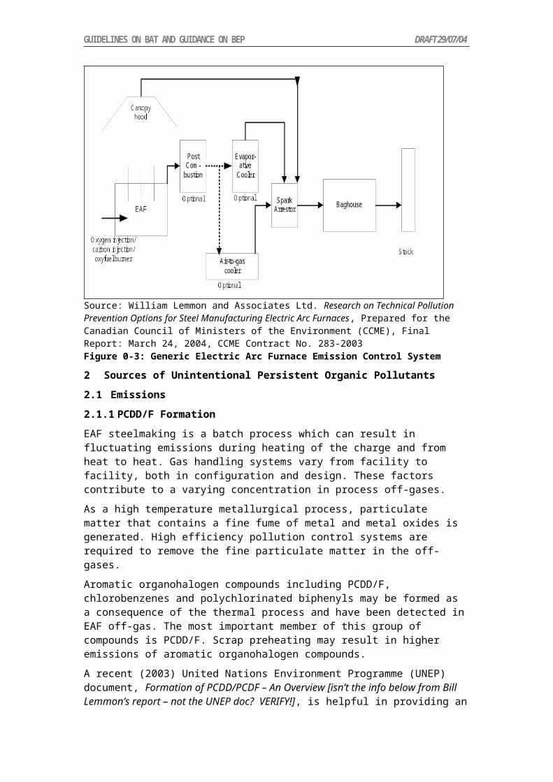
Measure Description Considerations Other Commentsgrinding techniques with good dust extraction and abatement. The resulting particles can be treated to recover valuable metals using density or pneumatic separation.
Elimination of plastic by stripping cable insulation (e.g. possible cryogenic techniques to make plastics friable and easily separable).
Sufficient blending of material to provide a homogenous feed in order to promote steady-state conditions.
Effective Process Control
Process control systems should be utilized to maintain process stability and operate at parameter levels that will contribute to the minimization of PCDD/PCDF generation. In the absence of continuous PCDD/PCDF monitoring, other variables such as temperature, residence time, gas components and fume collection damper controls should be continuously monitored and maintained to establish optimum operating conditions for the reduction of PCDD/PCDF.
For example, furnace temperatures should be maintained above 850 °C to destroy PCDD/PCDF.
Use flash smelting technology
Where pyrometallurgical techniques are used, use of flash smelting technology rather than older technologies (e.g., roasters, blast furnace, etc.) is a significant means to reducing energy use and to reducing emissions.
Flash smelting will also result in high concentration of sulphur dioxide in the off-gas stream, which would permit the efficient fixation or recovery of sulphur dioxide prior to off-gas venting.
Other general measures to prevent and reduce pollutant emissions:Maximize SO2 Content for Sulphur Fixation
Processes should be operated to maximize the concentration of the sulphur dioxide in the off-gas (where processing sulphide ores or concentrates), to enable recovery or fixation of the sulphur. Preference should be given to processes that use oxygen-enriched air (or pure oxygen) to raise the SO2 content of the process gas
Measure Description Considerations Other Commentsstream and reduce the total volume of the stream.
Secondary MeasuresThe following secondary measures can effectively reduce emissions of PCDD/PCDF and should be considered as examples of best available techniques.High Efficiency Gas Cleaning and Conversion of SO2 to Sulphuric Acid
SO2 rich off-gases, high efficiency pre-cleaning of off-gases followed by conversion of SO2 to sulphuric acid should be employed, and are together considered BAT.
This combination of techniques has the co-benefit of controlling dust and SO2 emissions, in addition to PCDD/PCDF.
Emission concentrations of PCDD/PCDF with use of high efficiency gas cleaning and conversion of SO2 to sulphuric acid are < 5 pg TEQ/m3.
Fume and Gas Collection
Air emissions should be controlled at all stages of the process, from material handling, smelting and material transfer points, to control the emission of PCDD/PCDF.
High Efficiency Dust Removal
Dusts and metal compounds should be removed to reduce PCDD/PCDF emissions. Very high efficiency dust removal techniques should be employed, for example, ceramic filters, high efficiency fabric filters or the gas cleaning train prior to a sulphuric acid plant.
Dust from dust control equipment should be returned to the process. Returned/collected dust should be treated in high temperature furnaces to destroy PCDD/PCDF and recover metals.
Fabric filter operations should be constantly monitored by devices to detect bag failure.
Preference should be given to fabric filters over wet scrubbers, wet electrostatic precipitators (ESPs), or hot ESPs for dust control.
Dust that is captured but not recycled will need to be disposed of in a secure landfill or other acceptable manner.
7 Achievable Performance and Emission Limits
Levels achieved at primary base metals smelting operations are noted as follows:Primary Base Metals Smelting
Source TypeAchievable Performance
Acid Plant Tail Gas (recovery of sulphur dioxide in off-gas from pyrometallurgical sources)
< 5 pg TEQ/Rm3
Off-gas dedusted by baghouse < 5 pg ITEQ/Rm3 to <30 pg TEQ/Rm3
Off-gas dedusted by ESP 30 pg TEQ/Rm3 to < 500 pg TEQ/Rm3

No final country emission limits were identified for emissions PCDD/PCDF, HCB or PCBs unintentionally produced by primary base metals smelters.

C . R E S I D E N T I A L C O M B U S T I O N S O U R C E S
1 Introduction
Heating and cooking in residential households with biomass is common practice in many countries. In most cases the fuel of preference is wood, however, other biomass fuels may be used. Biomass for residential heating and cooking is burned in a wide array of devices ranging from small, open pit stoves and fireplaces to large elaborate highly sophisticated wood burning stoves and ovens. PCDD/PCDF are formed as a result of incomplete combustion, typical in small devices with no or limited combustion controls.
Fossil fuel is also used extensively for domestic heating, especially in developed countries and in countries with economies in transition. Coal, (light fuel) oil and natural gas are the main sources for fossil fuel used for domestic heating.
The air emissions of the residential sources can be significantly higher than all industrial sources including power plants. According to the data of chemical analysis, residential sources may emit about three times more PCBs than industrial sources (excluding manufacturing industries), about two times more HCB, and about 25 times more PCDD/PCDF in countries with economies in transition (Table 1-3). It clearly shows the importance of the residential sources that are basically without any control.
Table 1: HCB emissions to the air in 2000Residential sources Quantity in Gg Emission factor in
g/GgEmission in kg
Hard coal 8102.8 0.125 1.01Wood 6901.0 0.06 0.41
Table 2: PCB emissions to the air in 2000
Residential sources Quantity in Gg Emission factor in g/Gg
Emission in kg
Hard coal 8102.8 31.6 256.05Brown coal 140.5 183.2 25.74Fuel oil 710.3 3.6 2.56Wood 6901.0 9.0 62.11Coke 410.0 9.7 3.98
Residential sources Quantity in Gg Emission factor in g/Gg
Emission in kg
Hard coal 8102.8 18 145 850.4Brown coal 140.5 10 1405.0Fuel oil 710.3 1 710.3Wood 6901.0 5 34 505.0
2 Biomass/Wood for Cooking and Heating in Developing Countries
Nearly 75-80% of the population in the developing world relies on wood and waste biomass as fuel for cooking and room heating. In most cases, the agricultural and forestry waste biomass is used as fuel, but in certain regions of the world, the demands of the domestic energy sector have put a severe pressure on the precious forest resources. This in itself is a cause for environmental concern. However, a more critical issue is that of the pollution of the indoor air due to the soot and smoke produced by inefficient combustion of biomass fuels inside the house.

Several studies conducted over the last couple of decades have revealed that poor indoor air quality is one of the major factors contributing to the poor state of health of rural women and children in the developing countries. In India 1.5% of the total deaths among women can be attributed to chronic diseases of the respiratory system.
The percentage of blindness and tuberculosis is the highest among women using traditional stoves, as compared to any other population group. Through several recent studies, a direct correlation is emerging between deaths and diseases in infants and young children, and use of wood and biomass as fuel in the house.
An important factor to be noted in this context is this: the number of untimely deaths is just one side of the coin. A general and chronic state of poor health or a disability like blindness adversely affects the way of life and that too must be borne in mind while assessing the health impact of poor indoor air quality. The seriousness of the problem is underlined when we note that the dependence of the global rural population on biomass energy is not expected to reduce significantly for at least a century or so. In fact, if studies of energy usage trends are anything to go by, the number of people relying on biomass energy is expected to increase over the next few decades.
2.1 BAT for Using Biomass/Wood for Cooking and Heating in Developing Countries
Biomass/wood stoves used in developing countries are not well designed. This leads to inefficient use of fuel during cooking and other heating purposes and in addition contributes to polluting the atmosphere due to incomplete combustion, which leads to many types of respiratory illnesses.
The simplest solution to the problem is to promote the so-called improved stoves. Some studies have indicated that improved designs save 50 to 80% fuel when compared with traditional ones. Possible designs for improved stoves would save fuel, reduce air pollution, be easy to manufacture/install and operate, and yet would be affordable to the rural users.
There are many kinds of designs of improved stoves and it is difficult to recommend any one particular type in this paper. Further research is needed in this area.
3 Vented and Unvented Appliances
Vented appliances are appliances designed to be used with a duct, chimney, pipe, or other device that carry the combustion pollutants outside a house. These appliances can release large amounts of pollutants directly into a house if a vent is not properly installed, or is blocked or leaking. Unvented appliances do not vent to the outside, so they release combustion pollutants directly into the house.
The table below identifies some typical appliance problems that cause the release of pollutants. Many of these problems are hard for a homeowner to identify.
COMBUSTION APPLIANCES AND POTENTIAL PROBLEMS
Appliances Fuel Typical Potential Problems
Central FurnacesRoom HeatersFireplaces
Natural orLiquefiedPetroleum Gas
Cracked heat exchanger;Not enough air to burn fuel properly; Defective/blocked flue; Maladjusted burner
Central Furnaces
Oil Cracked heat exchanger;Not enough air to burn fuel properly;Defective/blocked flue; Maladjusted burner
Central HeatersRoom Heaters
Wood Cracked heat exchanger; Not enough air to burn fuel properly; Defective/blocked flue; Green or treated wood
Central Coal Cracked heat exchanger; Not enough air to burn fuel properly; Defective
COMBUSTION APPLIANCES AND POTENTIAL PROBLEMS
Appliances Fuel Typical Potential Problems
FurnacesStoves
grate
Room HeatersCentral Heaters
Kerosene Improper adjustment; Wrong fuel (not-K-1); Wrong wick or wick height; Not enough air to burn fuel properly
Water Heaters Natural orLiquefiedPetroleum Gas
Not enough air to burn fuel properly; Defective/blocked flue; Maladjusted burner
Ranges; Ovens Natural orLiquefiedPetroleum Gas
Not enough air to burn fuel properly; Maladjusted burner; Misuse as a room heater
Stoves;Fireplaces
WoodCoal
Not enough air to burn fuel properly; Defective/blocked flue; Green or treated wood; Cracked heat exchanger or firebox
4 Best Environmental Practices
4.1 Ventilation
To reduce indoor air pollution, a good supply of fresh outdoor air is needed. The movement of air into and out of residential places is very important. Normally, air comes through cracks around doors and windows. This air helps reduce the level of pollutants indoors. This supply of fresh air is also important to help carry pollutants up the chimney, stovepipe, or flue to the outside. This also allows enough air for proper combustion and reduces the level of pollutants.
Use a hood fan, if using a range. Make sure that enough air is coming into the house when you use an exhaust fan. If needed, slightly open a door or window, especially if other appliances are in use. For proper operation of most combustion appliances and their venting system, the air pressure in the house should be greater than that outside. If not, the vented appliances could release combustion pollutants into the house rather than outdoors. If you suspect that you have this problem you may need the help of a qualified person to solve it.
4.2 Correct Use of Appliances and Fuel
It is important to understand the instructions on the manual of all appliances to understand how they work. Most importantly the recommended type of fuel that is needed for that appliance has to be well understood.
Only use water-clear ASTM 1-K kerosene for kerosene heaters. The use of kerosene other than 1-K could lead to a release of more pollutants. Gasoline is not to be used in a kerosene heater because it can cause a fire or an explosion.
Seasoned hardwoods should be used instead of softwoods in wood burning stoves and fireplaces. Hardwoods are better because they burn hotter and form less creosote, an oily, black tar that sticks to chimneys and stove pipes. Green or wet woods should be totally avoided. Never burn painted scrap wood or wood treated with preservatives, because they could release highly toxic pollutants. Plastics, charcoal, and colored paper such as comics, also produce pollutants. Unfortunately, in developed countries people use plastics as fuel.
4.3 Inspection and Maintenance
Combustion appliances are to be regularly inspected and maintained to reduce exposure to pollutants. It is important to clean chimneys and vents especially when changing heating systems.

INSPECTION AND MAINTENANCE SCHEDULES
Appliance Inspection/Frequency Maintenance/Frequency
Gas Hot Air Heating System
Air Filters - Clean/change filter - Monthly As needed; Look at flues for rust and soot - Yearly
Qualified person check/clean chimney, clean/adjust burners, check heat exchanger and operation - Yearly (at start of heating season)
Gas/Oil Water/Steam Heating Systems and Water Heaters
Look at flues for rust and soot - Yearly
Qualified person check/clean chimney, clean combustion chamber, adjust burners, check operation - Yearly (at start of heating season)
Kerosene Space Heaters
Look to see that mantle is properly seated - daily when in use;Look to see that fuel tank is free of water and other contaminants -- daily or before refueling
Check and replace wick -- Yearly (at start of heating season); Clean Combustion chamber -- Yearly (at start of heating season); Drain fuel tank -- Yearly (at end of heating season)
Wood/Coal Stoves Look at flues for rust and soot - Yearly
Qualified person check/clean chimney, check seams and gaskets, check operation -- Yearly (at start of heating season)
5 Further Recommendations
1) Issues resulting from residential combustion for cooking and heating in developed countries is of great concern. Research shows that health of women in some countries are deteriorating because of exposure to pollutants from improper practices for cooking and heating.
2) The concept of “improved wood stoves” has to be part of the National Implementation Plan for developing countries. This will enable countries to possibly access funds to do further research on the type of stove that is most suited to people.
3) Countries should strengthen awareness raising and education on residential combustion. These awareness programs have to be country specific.

GUIDELINES ON BAT AND GUIDANCE ON BEP DRAFT 29/07/04
D . F O S S I L F U E L – F I R E D U T I L I T I E S A N D I N D U S T R I A L B O I L E R S
1 Summary
Annex C Part III (d) of the Stockholm Convention identifies “fossil fuel fired utility and industrial boilers” as an industrial source category which “may unintentionally form or release” polychlorinated-dibenzo-p-dioxins and dibenzofurans (PCDD/PCDFs), polychlorinated biphenyls (PCBs) and hexachlorobenzene (HCB). It has been demonstrated that it is possible for these compounds to be unintentionally formed during the combustion of fossil fuels. The volumetric concentrations of these pollutants in the emissions from boilers are generally very low. However, the total mass emissions from the boiler sector may be significant because of the scale of fossil fuel combustion, in terms of both tonnage and distribution, for electricity generation and heat or steam production.
In summary, the following measures can be taken to decrease the formation and emission of PCDD/PCDFs, PCBs and HCB from the fossil fuel fired utility and industrial boiler sector:
Maintenance of efficient combustion conditions within the boiler and ensuring sufficient time is available to allow complete combustion to occur
Undertaking measures to ensure fuel is not contaminated with PCDD/PCDFs, PCBs or HCB
Where possible sourcing fuel low in components known to act as catalysts in the formation of PCDD/PCDFs
If fuels contaminated with PCDD/PCDFs, PCBs or HCB are to be combusted ensure that combustion chamber design and operation conditions are appropriate to maximize destruction during combustion, and minimize release to the environment
Rapid cooling through the critical temperature range (200-400°C) to minimise “de novo” congener formation
Use of appropriate gas cleaning methods to lower emissions which may contain entrained pollutants
Appropriate strategies for disposal, storage or ongoing use of collected ash
2 Introduction
Boiler design and operating conditions can have a significant impact on the production of persistent organic pollutants (POPs), so some general features of boilers are described here.
Boilers are facilities designed to burn fuel to heat water or to produce steam. The majority of boilers use fossil fuels to provide the energy source, although boilers can also be designed to burn biomass and wastes. The steam produced from the boiler can be used for electricity production or used in industrial processes; likewise hot water can be used in industrial processing, or for domestic and industrial heating. There are significant differences between utility and industrial boilers with the major differences occurring in three principal areas:
size of the boilers
applications for the steam and hot water produced by the boiler
design of the boilers.
Size: Modern industrial boilers (sometimes known as Industrial/Commercial/Institutional (ICI) boilers) are usually small in comparison to large utility boilers. A typical large utility boiler produces in the order of 1600 tonnes of steam per hour compared with about 45 tonnes of steam for the average industrial boiler, although industrial boilers may range from one tenth to ten times this size (CIBO, 2002).
Application of output steam: Utility boilers are designed to generate steam at a constant rate to power turbines for electricity production. Because of this constant demand for steam they tend to operate continuously at a steady state.

GUIDELINES ON BAT AND GUIDANCE ON BEP DRAFT 29/07/04
By contrast, industrial boilers have markedly different purposes in different industrial applications and the demands can vary depending on the industrial activities and processes operating at any given time and their demand for steam, for example the production and use of both hot water and steam for food processing when compared to the demand cycle in a large hospital boiler. These widely fluctuating steam demands mean that the industrial boiler does not generally operate steadily at maximum capacity. In general, industrial boilers will have much lower annual operating loads or capacity factors than typical utility boilers.
Boiler design: Utility boilers are usually large units combusting primarily pulverized coal, fuel oil or natural gas at high pressure and temperature. Individual utility boiler types tend to have relatively similar design and fuel combustion technologies. Industrial boilers however incorporate a wide range of combustion systems, firing a diverse range of combustible fuels including wastes from other industrial processes. Utility plant facilities are designed around the boilers and turbine(s) and their size allows for significant economies of scale in the control of emissions. However, the design of industrial boilers can be constrained by the necessity for flexibility of steam output and plant space limitations. This may lead to more difficulty in applying effective emission controls to these industrial boiler applications.
2.1 Boiler Types
Utility boilers: are usually designated by the combustion furnace configuration:
Tangentially-fired – commonly used for pulverized coal combustion but may be used for oil or gas; single flame zone with air-fuel mixture projected from the four corners of the furnace tangential to furnace centre line
Wall-fired – multiple burners located on a single wall or on opposing furnace walls can burn pulverized coal, oil or natural gas
Cyclone-fired – typically crushed coal combustion, where the fuel air mixture is burned in horizontal cylinders
Stoker-fired – older plants burning all solid fuel types- spreader stokers feed solid fuel onto a combustion grate and remove ash residue
Fluidised bed combustion (FBC) – lower furnace combustion temperature, efficient combustion promoted by turbulent mixing in the combustion zone, crushed coal feed with the potential for sorbent additions to remove pollutants, particularly sulfur dioxide
Pressurised fluid bed combustion (PFBC) – similar to FBC, but at pressures greater than atmospheric, and with higher efficiency
Industrial/Commercial/Institutional (ICI) boilers are normally identified by the methods of heat transfer and combustion system utilised. A detailed discussion of the various ICI boiler types can be found in Oland, 2002. In summary:
Heat transfer systems
Water tube boilers – heat transfer tubes containing water are directly contacted by hot combustion gases. Commonly used in coal fired boilers but can accommodate almost any combustible fuel including oil, gas, biomass, municipal solid waste (MSW), tyre derived fuel (TDF) and refuse derived fuel (RDF).
Fire tube boilers – water surrounds tubes through which hot combustion gases are circulated, the application is more common for pulverized coal, gas and oil fired boilers but various types can also burn biomass and RDF. Generally used for lower pressure applications.
Cast iron boilers – cast sections of the boiler contain passages for both water and combustion gas, used for low pressure steam and hot water production, generally oil or gas fired with a smaller number of coal fired units.

GUIDELINES ON BAT AND GUIDANCE ON BEP DRAFT 29/07/04
Combustion systems
Stokers - There are a variety of different stoker types and functions. Underfeed stokers supply both fuel and combustion air from below the grate discharging ash to the side or rear. Overfeed stokers which may be mass-feed or the more popular spreader stoker, supply the combustion air from below the grate with the fuel for combustion being distributed above the grate. Spreader stokers with a stationary grate are used extensively in the sugar industry to combust bagasse.
Burners – include a diverse group of devices which manage the delivery of fuel/air mixtures into the furnace under conditions of velocity, turbulence and concentration appropriate to maintain both ignition and combustion.
3 Generation of Dioxins, Furans, PCBs and HCB from combustion
In a properly operated combustion system, waste stream volatiles should be subjected to sufficient time at high temperature, with adequate oxygen and mixing to enable uniform and complete combustion. When those conditions are not present the potentially toxic airborne emissions, polychlorinated biphenyls, (PCBs), hexachlorobenzene (HCB), polychlorinated dibenzo-p-dioxins (PCDDs) and furans (PCDFs), can be produced in or survive the combustion process (Van Remmen 1998, UNEP, 2003a).
3.1 Dioxins and Furans
Dioxins and furans are tricyclic halogenated aromatic hydrocarbons, comprising two benzene rings connected by two oxygen atoms at adjacent carbons on each of the benzene rings in PCDDs and by one oxygen atom and one carbon-carbon bond in PCDFs, and at least one chlorine atom substituted for hydrogen; the basic structures are shown in Figure 1.
Both groups of chemicals may have up to eight chlorine atoms attached at carbon atoms 1 to 4 and 6 to 9. Each individual compound resulting from this is referred to as a congener. The number and position of chlorine atoms around the aromatic nuclei distinguish each specific congener. In total, there are 75 possible PCDD congeners and 135 possible PCDF congeners. The most widely studied of the PCDDs and PCDFs is 2,3,7,8-tetrachlorodibenzo-p-dioxin (TCDD), as it has the highest toxicity of this class of compounds.
These compounds have been shown to have a range of toxicities with some causing lethal effects in laboratory animals at very low levels. Toxic effects of PCDD/PCDFs appear to be species specific. Variation in effects occurs between congeners and extrapolation of animal data to humans is controversial, as most human data has been derived from uncontrolled occupational or accidental exposures (Williams, 1994, Kervliet N. in Manno, 1995).
Congeners containing one, two or three chlorine atoms are thought to be of little toxicological significance. However, 17 congeners with chlorine atoms substituted in the 2, 3, 7 and 8 positions (i.e. in the lateral positions of the aromatic rings) are thought to pose a health and environmental risk.
When found in the environment, biological tissues and industrial sources, the PCDDs and PCDFs are usually present as complex mixtures and the different congeners vary significantly in their toxicity. However, the potency of different dioxins can be ranked relative to TCDD, the most toxic member of the dioxin class. These rankings are known as toxic equivalency factors (TEFs).
The most recent review of TEFs was that of the World Health Organisation (WHO) in 1998 (Van den Berg et al, 1998). This review has subsequently been recognised by the United States Environmental Protection Agency (USEPA) as being the most appropriate scheme for estimating the toxicity of dioxin mixtures (USEPA, 2000a). Under the WHO TEF scheme shown in Appendix A, TCDD is assigned a TEF of 1.0, and other PCDDs and PCDFs have TEF values ranging from 1.0 down to 0.0001. To be included in the TEF scheme, a PCDD or PCDF must bind to the cellular aryl hydrocarbon (Ah) receptor, elicit Ah receptor-mediated

GUIDELINES ON BAT AND GUIDANCE ON BEP DRAFT 29/07/04
biochemical and toxic responses, must be persistent, and accumulate in the food chain (WHO, 1998). To estimate the toxic potency of a given mixture of PCDDs and PCDFs, the mass concentration of each individual component is multiplied by its respective TEF, and the products are summed to represent the TCDD toxic equivalence (I-TEQ) of the mixture. The WHO TEF scheme also includes those PCBs congeners that are considered to exhibit dioxin-like characteristics for which the WHO has also developed toxicity equivalency factors to TCDD ranging from 0.1 down to 0.00001.
O
O
1
2
3
46
7
8
9
Clx Cly
PCDD
O
1
2
3
46
7
8
9
Clx Cly
PCDF
O
O
Cl
Cl
Cl
Cl
2,3,7,8- tetrachlorodibenzo-p-dioxin (2,3,7,8-TCDD)
Figure 1: Generalised structure for PCDD/PCDFs,
PCDD/PCDFs have atmospheric ‘lifetimes’ of up to 30 days, allowing long distance transportation (Atkinson, 1996). The PCDDs and PCDFs have very low water solubility, high octanol-water partition coefficients, low vapour pressure and adsorb strongly to particles and surfaces and are resistant to chemical degradation under normal environmental conditions. Thus, they are persistent in the environment and their high fat solubility results in their bioconcentration in biota and accumulation in the food chain. Almost all 210 individual PCDD and PCDF congeners have been identified in emissions from thermal and industrial processes and consequently they are found as mixtures in environmental matrices such as soil, sediment, air, plants and lower animals, although their low aqueous solubility means they can hardly be detected in water and are largely immobile in soils. Given that they are possibly highly toxic, I-TEQ emission standards are set at very low levels.

GUIDELINES ON BAT AND GUIDANCE ON BEP DRAFT 29/07/04
A 1995 US survey of emissions of dioxin-like substances to air indicated that those contributed from combustion sources were higher (by an order of magnitude) than those from all other categories. However, the emissions from combustion were dominated by five source categories (municipal solid waste incineration, medical waste incineration, cement kilns burning hazardous waste, forest, brush and straw fires, and secondary copper smelting) that accounted for more than 90% of emissions (USEPA, 2003). It should be noted that these categories do not include fossil fuel combustion in utility or industrial boilers which are believed to generate significantly lower levels of PCDDs and PCDFs (Sloss and Smith, 1993, Sloss, 2001, Dyke, 2004).
3.1.1 PCDD/PCDF Formation Mechanisms
PCDDs and PCDFs probably arise by a variety of formation mechanisms. Figure 2 shows a schematic representation (modified from Richards, 2004) of possible locations for PCDD/PCDFs formation in a boiler
Figure 2: Location of possible PCDD and PCDF formation in a boiler (modified from Richards, 2004)
The three general mechanistic pathways which occur in overlapping temperature ranges have been identified for dioxin and furan formation in combustion (Williams, 1994; Edulgee, 1994; Lemieux, 1998; Zevenhoven and Kilpinen, 2001) are represented in Figure 3 (after Eduljee, 1994). These formation pathways are:
1. Undestroyed PCDDs and PCDFs originally in the fuel, and which survive due to poor destruction efficiency. This has been discounted as a significant source of PCDD/PCDFs, since their emissions often exceed the maximum release rate calculated on the basis of feed concentration, suggesting a genuine mechanism for formation from precursor compounds within the fuel (Edulgee, 1994). However, conditions undoubtedly exist for the thermally stable PCDDs and PCDFs to survive the combustion process, particularly at the lower combustion temperatures in certain zones of some inefficient or ineffective combustion devices.
2. Gas-phase formation at temperatures of 300- 800C. This mechanism results from the conversion of precursors such as polychlorinated biphenyls (PCBs), chlorinated

GUIDELINES ON BAT AND GUIDANCE ON BEP DRAFT 29/07/04
benzenes, and pentachlorophenols. The in situ synthesis of PCDDs and PCDFs results from rearrangement, free-radical condensation, dechlorination, and other molecular reactions. These compounds may be present in some forms of waste, particularly hazardous waste, or can be formed by the combustion of plastics such as polyvinyl chloride (PVC).
There is no simple, direct relationship between PVC combustion and PCDD and PCDF formation. In particular, the presence or absence of plastics containing chlorine or HCl does not correlate with variations in PCDD and PCDF levels. (Eduljee and Cains, 1996). Although some laboratory tests have shown a correlation between chlorine and PCDD/PCDFs under certain conditions, the effects of combustor design, operating practice and variability of emissions level measurements at the limits of detection mask any discernible change in commercial scale systems. It is suggested that consistent improvements in PCDD/PCDF stack concentrations are unlikely to be realised by reducing the chlorine content of the combusted material (Rigo et al, 1995). This can be seen logically because given the small amount of PCDDs and PCDFs ever produced, commercial systems are seldom if ever “starved” of chlorine bearing components to the extent that would be necessary to affect the levels of PCDD/PCDFs produced. The temperature range of formation is 300-800C.
3. Solid-phase particle mechanisms at temperatures less than 500C. PCDDs and PCDFs are produced as a result of elementary reactions of the appropriate elements: carbon, hydrogen, oxygen and chlorine. This reaction is called a de novo synthesis of PCDD and PCDF. De novo synthesis has been cited to take place in the combustion plasma, or in the exhaust train after combustion. PCDDs and PCDFs have also been shown to form on flyash containing residual carbon collected within a particular combustion system. Presence of HCl, O2 and H2O is required, and temperatures of 250-400°C (Buerkens and Huang, 1998). The reaction is catalysed by various metals such as iron and copper, metal oxides, silicates, etc present in the flyash (Williams, 1994, Lohmann and Jones, 1998). Support for the viability of the de novo mechanism is the observation of low levels of PCDDs and PCDFs in the furnace exits of incinerators but levels sometimes 100 times greater have been found in the electrostatic precipitator ash from the same plants (Hagenmaier et al, 1988). The extent of the contribution of the de novo mechanism depends on:
The cooling rate of the flue gas, especially around 300°C The amount of fly ash The presence of trace elements, especially iron and copper The carbon and chlorine content of the fly ash The presence of free oxygen
Thus, this mechanism has the potential for producing PCDD/PCDFs when a solid fuel is combusted and the fly ash is collected in some form of air pollution control device. However accurate estimation of the concentrations and amounts formed is extremely difficult since there is a very strong dependence of formation rates on process design and operating conditions.

GUIDELINES ON BAT AND GUIDANCE ON BEP DRAFT 29/07/04
>200°C
200 – 400°C
850 – 1200°C
Adsorbed PCDDs and PCDFs
Desorbed PCDDs and PCDFs
Surface catalysed reactions on flyash , between POHCs, PICs, and chloride/chlorine
Combustion Fuel (virgin and/or waste materials)
Organics Chlorine, Chlorides Non-combustibles
PIC
emissions
POHC
emissions
HCl,
chlorides
Metals, Non-
combustibles
Figure 3: Schematic representation of possible post-combustion PCDD/PCDF formation2.1.2 Dioxin and Furan Control Mechanisms
Combustion conditions, fuel quality and plant design and operating conditions can have a major influence on PCDD formation. It has been shown (Williams, 1994; Edulgee and Cains, 1996) that combustion conditions can be improved to reduce dioxin emissions. Lemieux (1998) summarises work at the USEPA, which shows in decreasing order of importance, the parameters which can be controlled to reduce PCDD/PCDF emissions:
Combustion quality as indicated by- Carbon monoxide (CO), total hydrocarbons, soot formation- Particle entrainment and burnout
Quench rate and air pollution control temperatures Fuel/waste parameters
- Sulphur- Metals- Chlorine
These can be achieved by the following conditions (Lemieux, 1998): Uniform high combustor temperature Good mixing with sufficient air Minimise entrained, unburned particulate matter Feed rate uniformity Active monitoring and control of CO and total hydrocarbons
Finally a number of operating parameters for air pollution control devices have been identified to result in lower dioxin and furan emissions. These are:
Low temperature at the particulate control device inlet Minimisation of gas/particle residence time in the 200-400C temperature
window Rapid quench from furnace temperatures to air pollution control device
temperature, to ensure that time in the 200-400°C temperature window is below one second (see Section 5.2)

GUIDELINES ON BAT AND GUIDANCE ON BEP DRAFT 29/07/04
Presence of sulphur has also been shown to inhibit dioxin formation, based on the generally low emissions from coal-fired power plants, and results obtained from the co-firing of high sulphur coal with refuse derived fuel (Tsai M-Y et al., 2002). Thus there may be benefits in maintaining a reduced Cl:S ratio (~0.1) (Luthe et al., 1997), although it should be recognised that the use of high sulphur fuels may result in the development of a different set of air pollution problems.
3.2 PCB and HCB
3.2.1 Polychlorinated Biphenyls (PCBs)
PCBs are a group of synthetic organic chemicals that can cause a number of different harmful effects. There are no known natural sources of PCBs. They are either oily liquids or solids and are colourless to light yellow. Some PCBs are volatile and may exist as a vapor in air. They have no known smell or taste. PCBs enter the environment as mixtures containing a variety of individual chlorinated biphenyl components, known as congeners, as well as impurities. Because they don't burn easily and are good insulating materials, PCBs were used widely and are still used in some countries as coolants and lubricants in transformers, capacitors, and other electrical equipment (ATSDR, 2004). There are 209 PCB congeners, 13 of which are thought to have dioxin-like toxicity; these are PCBs with 4 or more chlorine atoms with just one or no substitution in the ortho position (USEPA, 1998a). A generalized structure for polychlorinated byphenyls (PCBs) is shown in Figure 4.
Primarily PCB emission is from the incomplete combustion of sources containing PCB. There is also some evidence that PCB can form in combustion systems by mechanisms similar to that by which PCDD/PCDFs are formed; gas phase formation and de novo synthesis from carbon and chlorine in the presence of particulate ash (Dyke, 2004). PCBs are also possible precursors for the formation of dioxins and furans during combustion processes (Ruuskanen, Vartiainen et al., 1994). The chlorine-carbon bonds in PCBs are temporarily destroyed in boilers and dioxins and furans are formed after these elements and emitted from the boiler in the stack when temperatures fall below 800°C (BREDL, 2000). Therefore, there is a correlation between PCDD/PCDFs and PCB emissions (Ruuskanen, Vartiainen et al.,1994).
Similar emission control strategies to those used for minimising PCDD/PCDF emissions can be used with fuel type and particularly combustion conditions determining PCB emission levels.
3 2
1
65
4 1'2' 3'
4'
5' 6' ClyClxFigure 4: Generalised structure for polychlorinated biphenyls (PCBs), x+y=1 to 102.2.2 Hexachlorobenzene (HCB)
HCB is a white crystalline solid with low solubility in water. It does not occur naturally in the environment. It is a toxic compound that is persistent in the environment and is bio-accumulative. For these reasons, it is classified as a persistent organic pollutant (POP). A structure diagram for HCB showing chlorine atoms attached at all available ring positions is shown in Figure 5.
HCB has been used in the past as a fungicide for seed treatment of wheat, onions, and sorghum. It is also found as an impurity in several pesticide formulations and as an industrial by-product. A substantial portion of HCB measured in the atmosphere is thought to come

GUIDELINES ON BAT AND GUIDANCE ON BEP DRAFT 29/07/04
from volatilisation of “old” HCB on the soil from past contamination (Bailey, 2001). Combustion processes are another significance source and the major emission points are similar to the ones for dioxins and furans: waste incineration, thermal metallurgical industries, use of chlorinated fuels in furnace installations, combustion of fossil fuels, firing of chlorinated compounds, use of solvents and wood preservers and electric arc furnaces (EEAA, 2004).
When considering HCB emitted from combustion processes, coal combustion is the third largest global source (Bailey, 2001). The production of chlorinated aromatics from a combustion plant is influenced by the chlorine content of the fuel and the operating conditions. It appears that the production of HCB can be correlated to the production of other chlorinated aromatics such as dioxins and furans (Oberg and Bergstrom, 1985). Therefore, measures for the control of HCB emissions are similar to the ones used for dioxins and furans.
Cl
Cl
ClCl
Cl
Cl
Figure 5: Structure for hexachlorobenzene (HCB)
3. Types of FuelsVarious types of fuels such as coal, oil, gas and biomass are used either individually or in combination with energy containing waste products from other processes, for steam generation in boilers. The type of fuel used depends on fuel availability and process economics. PCDD/PCDFs (and other POPs) can be formed in most combustion systems, including those burning the previously mentioned fuel types (USEPA, 1998a).
In large, well-controlled fossil fuel power plants, the formation of PCDD/PCDFs (and other POPs) is low since the combustion efficiency is usually high, the process is stable and the fuels used are generally homogeneous. However, significant mass emissions are still possible as large volumes of flue gases are emitted with small concentrations of PCDD/PCDFs (UNEP, 2003a). In smaller less well controlled systems there exists the potential for POP emissions at greater concentrations but at lower overall throughputs and therefore resulting in lower mass emission of POPs.
3.3 Fossil Fuel Combustion
3.3.1 Heavy Fuel Oil
Heavy fuel oil is combusted for both steam generation and power generation purposes and is usually burned in specially designed burners incorporated in the boiler walls. The formation of PCDD/PCDFs is favoured during co-combustion when liquid or sludge wastes such as waste oil or used solvents are added to the fuel mix (UNEP, 2003a), possibly due to lowered combustion efficiency.
3.3.2 Light Fuel Oil and Natural Gas
Light fuel oil and natural gas are always fired in specially designed burners and are generally unlikely to generate large amounts of PCDD/PCDFs since both are very high calorific, clean burning fuels with little ash. If liquid or sludge waste is co-fired, then higher concentrations of
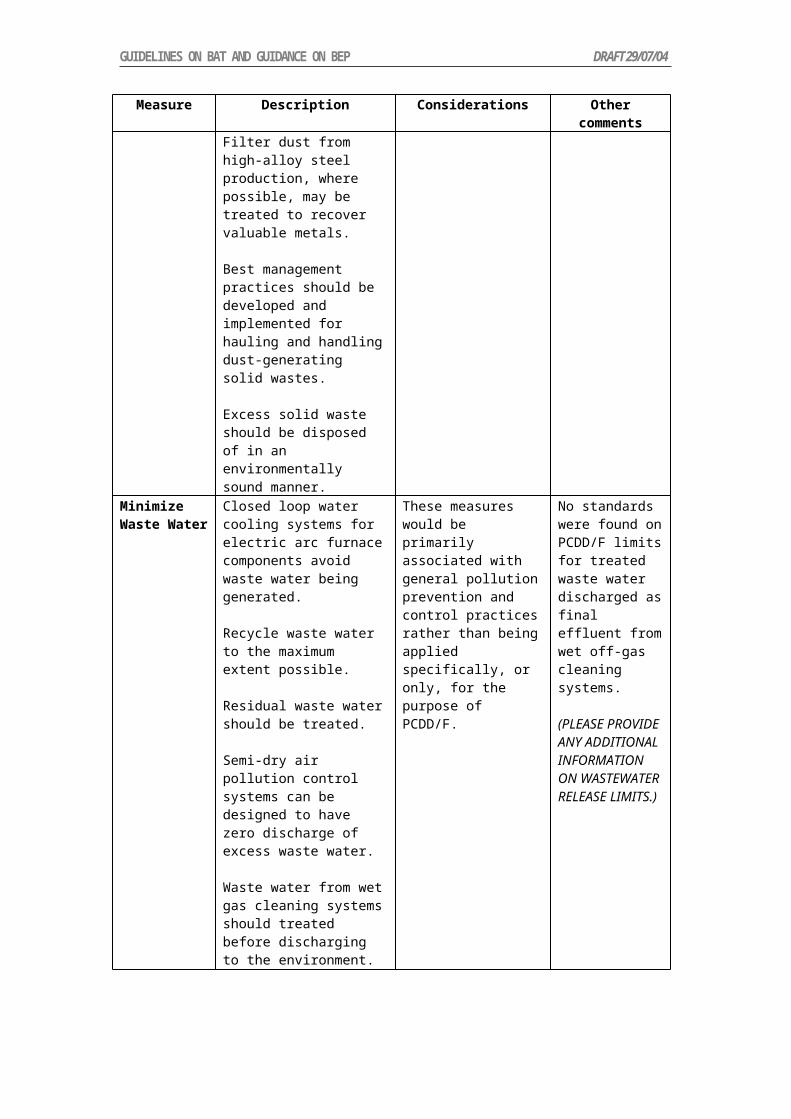
GUIDELINES ON BAT AND GUIDANCE ON BEP DRAFT 29/07/04
PCDD/PCDFs can be expected (UNEP, 2003a). Increased gas use for power generation (as a replacement fuel for coal and oil) will result in reductions of PCDD/PCDFs from the generation sector (Aarhus Convention, 1999).
3.3.3 Coal
Efficient coal combustion in large coal-fired power plants results in very low levels of organic emissions (Rentz et al, 2002). Coal use in less efficient sectors could be a significant source of local emissions (Sloss, 2001). The 1998 UNECE POPs protocol recommends the improvement of energy efficiency and energy conservation for utility and industrial boilers over 50 MW as an emissions reduction strategy due to lowered fuel requirements. However, it is acknowledged that while techniques for the reduction of particles, SOX and NOX may result in the reduction or removal of PCDD/PCDFs (and presumably PCBs and HCB) removal efficiencies will be variable. No Best Available technology (BAT) was identified for PCDD/PCDF removal in the boiler sector and chlorine removal from fossil fuel feeds was not seen as a cost-effective for PCDD/PCDF reduction (Aarhus Convention, 1999).
3.4 Biomass Co-burning as a Supplement to Fossil Fuel Energy
The use of biomass energy derived from renewable animal and plant sources can contribute to the energy requirements of both industrial and utility boilers. Usually the combustion of renewable biomass is less efficient than conventional fossil fuels and it is mostly burnt as a supplement along with feed from a conventional fossil fuel energy source (Olsen, 2001). There are exceptions to this, for example, the combustion of bagasse in the sugar industry and wood waste (hogged fuel) in paper pulping to fire boilers and generate power. When used in co-generation plant biomass wastes are often supplemented by fossil fuel to ensure process efficiency and stability (Magasiner, 1996 and Magasiner et al., 2002). Alternatively, smaller stand-alone biomass combustion/generation systems have been constructed. As the flue gases from these units contain high moisture levels they usually require the addition of flue-gas condensation systems which are claimed to trap “most dioxins” (Yan et al., 1997)
As stated previously, most electricity-generating plants use a single fuel, but it is possible to modify the boiler and the fuel processing equipment to blend wood or some other biomass into the fuel mix. This process of co-firing means that more than one fuel type is used simultaneously. Percentages of included co-fired biomass are generally low (<5%) but may range up to 20% where separate biomass injection systems are employed (Olsen, 2001). Potential for POPs emission may be increased by co-firing if boiler efficiency is not maintained by appropriate system redesign or control. When biomass co-burning is used effectively it does not appear to increase PCDD/PCDF production and may improve particulate collection due to the increased flue duct moisture (Tillman, 2000).
3.5 Waste Co-burning
Alternative fuels (also known as waste-derived fuels) are materials that are rich in energy, such as used tyres, waste wood, used oil and spent solvents, which can be used to replace fossil fuels as a source of thermal energy. Potential contamination of alternative fuels by undesirable waste materials/substances is an issue associated with this fuel source. In particular, the presence of PCBs, HCB and chlorine in the alternative fuel should either be specifically precluded, or limited.
For disposal of low concentration PCB liquids, high efficiency boilers can sometimes be used. These boilers, used for steam and/or electricity generation, are fired by oil, coal or natural gas, and often approach the time and temperature combustion characteristics of liquid injection incinerators. Cost benefits in using boilers to destroy PCBs include energy recovery and lower transportation costs. Boilers, however, are often limited in their destruction capabilities due to a lack of hydrogen chloride emission control and sometimes by combustion condition limitations and possible boiler corrosion problems.

GUIDELINES ON BAT AND GUIDANCE ON BEP DRAFT 29/07/04
As a general rule, the use of boilers should be limited to low level PCB liquid wastes with concentrations of PCBs less than 500 parts per million (Environment Canada, 2004). US regulations require that if liquid PCBs are to be incinerated, the combustion efficiency must be at least 99.9%. If non-liquid PCBs are incinerated, the mass air emission must be no greater than 0.001 g PCB/kg of PCB combusted (IPEN, 2003).
Fuel quality management and good combustion conditions in combination with an effective collection device appears to offer the most successful control strategy for POPs minimisation when waste material is included amongst the fuel loading. For the most effective operation waste materials should be specifically excluded from the process during start-up or shutdown when combustion conditions are less likely to be both stable and controlled.
4 Estimation of POPs Emissions from Boilers
Measurement of the low levels of PCDD/PCDFs, PCBs and HCB from the combustion of fossil fuels in boilers is technically challenging and costly compared with the measurement of criteria pollutants such as sulphur dioxide, oxides of nitrogen and particulates. Although the direct measurement of POPs from individual facilities is encouraged to improve the knowledge base of emissions of these toxic components, it is acknowledged that in some circumstances this may not be possible except for those operating large and technically advanced facilities. In an efficient combustion process the levels of pollutant may be up to several orders of magnitude below the emissions acceptable from incineration (Brain et al. cited in Sloss, 2001). As a result, although PCDD/PCDFs, PCBs and HCB may possibly be present, they may be below the detection limits of currently available analytical methods.
An alternative to direct measurement is the calculation of an imputed emission output given some knowledge of fuel type, throughput and process conditions. PCDD/PCDF emission factors (I-TEQ) for a number of boiler processes are given in Tables 1 and 2., with additional information on emission of particular congeners included as Appendix B. UNEP have developed a comprehensive set of guidelines for estimation of PCDD/PCDFs across all sectors including those for boilers burning fossil fuels (UNEP, 2003a).
Table 1: Emission factors (to air) for PCDD/PCDFs from the combustion of various fuel sources (based on fuel consumption)
Process Fuel Emission Factor (I-TEQ)
Emission Factor (TEQ-WHO)
Reference
Utility/Industrial boilers
Oil 0.314 ng/L
0.083-0.147 ng/L
0.366 ng/L
0.094-0.167 ng/L
USEPA (1997)*
EPRI (1994)*
Utility/Industrial power plants
Coal74 0.079-1.24 ng/kg
0.2-0.36 ng/kg
0.078-1.31 ng/kg USEPA (1997)*
NZ Environment Ministry (2000)
Kraft black liquor recovery boilers
Black liquor solids
0.10-0.15 ng/kg
0.029-0.065 ng/kg
0.07 ng/kg
0.10-0.16 ng/kg
0.028-0.072 ng/kg
USEPA (1987)*
NCASI (1995)*
UNEP (2003a)
Industrial wood combustors
Wood
Bark boiler
0.56-0.58 ng/kg
0.4 ng/kg
0.60-0.62 ng/kg USEPA (2000b)
UNEP (2003a)
Power boiler Salt-laden hogged wood waste
36-270 ng/kg fuel n/a Luthe (et al.) 1997
74 Assuming that approximately 10 m3 of air /kgcoal is used for combustion, this suggests that volumetric emission rates in the range of 0.008- 0.124 ng/m3 would be achieved for coal combustion.

GUIDELINES ON BAT AND GUIDANCE ON BEP DRAFT 29/07/04
Process Fuel Emission Factor (I-TEQ)
Emission Factor (TEQ-WHO)
Reference
23-28 ng/kg fuel**
*sources cited in USEPA (2000b) ** superior combustion conditions n/a not available
Results of PCB measurements on a coal-fired power station using recovered oil for start up calculated a WHO-TEQ for PCB of 0-0.022 ng/Nm3 (with more than half of the congeners below the detection limit). These emissions are extremely low when compared to the allowable limits for PCDD/PCDF emissions, which are often set at 0.1 ng I-TEQ/Nm3 (Dyke, 2004).
Information on emissions is more readily available for PCDD/PCDF emissions than PCBs and HCB. Where waste materials comprise a significant proportion of the fuel feed it may be appropriate to source emission factors from the waste incineration sector (refer UNEP, 2003a). For comparative purposes the suggested emission factors for the combustion of municipal solid waste are included as Table 3.
Table 2: Emission factors* for PCDD/PCDFs from the combustion of various fuel sources (energy throughput basis - µg TEQ/TJ of fuel consumed)
Process Fuel Air emissions Water emissions Residue
Power boiler Fossil fuel/waste co-firing
35 ND ND
Power boiler Coal 10 ND 14 (fly ash)
Power boiler Heavy fuel oil 2.5 ND ND
Power boiler Light fuel oil/natural gas
0.5 ND ND
*These default emission factors are based on the assumption that the fuels burned lead to PCDD/PCDF releases associated with the disposal of fly ash. Emissions through bottom ash are negligible. The removal efficiency of particulate matter also increases with the quality of air pollution control (APC) system employed at the plant (UNEP, 2003a).
Table 3: Emission factors* for municipal solid waste incineration (ng TEQ/kg MSW burned)
Process Air emissions Fly Ash Bottom Ash
1. Low technology combustion, no APC system 3500 - ND
2. Controlled combustion, minimal APC 350 500 15
3. Controlled combustion, good APC 30 200 7
4. High technology combustion, sophisticated APC system 0.5 15 1.5
*Emission factors are based on the assumption that the waste burned leads to about 1–2 % of fly ash and 10–25 % bottom ash. The removal efficiency of particulate matter increases with the quality of the plant. Class 1 emission factors should be chosen for very small (< 500 kg/h) and simple furnaces operated in a batch type mode without any APC system attached to the back end. Class 4 should only be used for highly sophisticated MSW incineration plants as found in some Western European countries as well as occasionally in North America. Class 4 values should be applied only if a

GUIDELINES ON BAT AND GUIDANCE ON BEP DRAFT 29/07/04
regulatory value equivalent to 0.1 ng TEQ/Nm³ (@11 % O2) is strictly enforced, and the facility is in compliance. The vast majority of all MSW incineration plants can be assumed to fall into Classes 2 and 3 (UNEP, 2003a)
4.1 Emission Data Gaps
For accurate estimation of emissions more comprehensive emission factor data are required for all sources. The available data are extremely limited and subject to considerable uncertainty, and the resultant emission estimates need to be interpreted with much caution. For, PCB and HCB emissions little or no reliable data is available for the boiler combustion sector.5 Best Environmental Practices (BEP)
The best environmental practices described in this section are general guidance applicable to any kind of boiler, regardless of its size or type:
Identify key process parameters, either from site-specific investigations or research undertaken on similar facilities elsewhere.
Introduce measures that enable control of key process parameters. Introduce monitoring and reporting protocols for key process parameters. Introduce and follow planning cycles, implement appropriate inspection and
maintenance cycles. Introduce an environmental management system which clearly defines
responsibilities at all levels. Ensure adequate resources are available to implement and continue best
environmental practice. Introduce process improvements to reduce technical bottlenecks and delays. Ensure staff are appropriately trained in the application of the BEPs relevant to their
duties. Define a fuel specification for key fuel parameters and introduce a monitoring and
reporting protocol. When co-firing biomass or waste, the, alternative fuels should not be added until the
boiler furnace combustion conditions are stable and it has reached its operating temperature.
While the introduction of fuels containing POPs compounds or chlorine is possible, their proportion as co-fuel should be limited in order to allow proper destruction.
6 Best Available Techniques (BAT)
As discussed in Section 3, unintentional production of POPs compounds such as PCDDs, PCDFs, PCBs and HCBs during the combustion processes follow three general pathways:
Undestroyed compounds originally present in the fuel Gas-phase formation from precursors (e.g. polyhalogenated phenols, chlorinated
aromatic compounds…) at temperatures higher than 500ºC Re-formation of POPs in the cooling flue gases
In order to reduce the emission of POPs from fossil fuel-fired utility and industrial boilers, these three pathways must be minimised in the design and operation of the process. This will be effectively achieved by addressing:
Fuel quality Combustion conditions and Installation of the most appropriate air pollution control devices (APCDs).

GUIDELINES ON BAT AND GUIDANCE ON BEP DRAFT 29/07/04
6.1 Primary Measures
6.1.1 Fuel Specification and Monitoring
While the low level of precursors necessary to promote the unintentional formation of POPs via gas formation above 500ºC occur in most fuels, attention must be paid to reduce, as much as is possible, the unintentional introduction of contaminated fuels, which may promote the formation of POPs. This is especially valid when co-firing fossil fuels with waste material. Controls should be introduced to ensure that the fuels used are within the required specifications.
6.1.2 Combustion Conditions
To achieve the complete combustion of POPs contained in the fuel, special attention must be paid to the four cornerstones of high destruction efficiency: temperature, time, turbulence and excess oxygen (McKay, 2002). This will also ensure the destruction of precursors and reduce soot formation and therefore provide fewer possible sites for solid catalysis in the cooling gas effluent. Table 4 illustrates the influence of combustion conditions on emission of pollutants from refuse derived fuel (RDF). While the values in Table 4 are higher than might be expected from combustion using fossil fuels the values illustrate the significant influence of combustion conditions (Environment Canada cited in Dyke, 2004).
Table 4: Trace organic concentrations (ng/Sm3 at 12% CO2) for RDF combustion
Species Good Combustion Poor CombustionPCDD (total) 70-230 200-600PCDF (total) 220-600 700-1,300Cl3-6 benzenes* 4,000-6,000 7,000-16,000* includes all of the congeners of tri, tetra and penta as well as the fully substituted hexa
It is generally accepted that a temperature in excess of 900ºC (McKay, 2002) and a gas residence time of 2 seconds are sufficient to achieve complete oxidation dioxins as long as the gas flow is sufficiently turbulent and excess O2 is present. As temperature and residence time are inversely related, when the furnace temperature is 1000ºC, only one second at temperature is sufficient (McKay, 2002). However, as shown in Figure 6 (modified from Richards, 2004), temperatures over 900ºC are necessary to destroy the pollutants and to reduce the levels of organic precursor compounds. To ensure that all POPs are oxidised, McKay suggests a furnace temperature higher than 1000ºC.
Figure 6: Destruction temperatures for various halogenated aromaticsOther important factors are the excess air and turbulent conditions in the furnace. High degrees of turbulence will avoid the formation of cold pockets (or quenching zones) where oxidation temperatures will not be reached. High turbulence will also lead to uniform distribution of oxygen to ensure total combustion, avoiding sub stoichiometric zones,

GUIDELINES ON BAT AND GUIDANCE ON BEP DRAFT 29/07/04
providing that air is in excess. To assess the efficiency of combustion, real time monitoring of CO can be useful. High CO levels indicate incomplete combustion and conditions under which POPs may survive and/or be created.
When solid fuel is used in order to maximise mixing and combustion conditions, low moisture pulverised fuels are to be preferred to crushed or lumpy fuels. Evaporation is an endothermic reaction and when moisture is introduced in the furnace, combustion temperature decreases. Introducing pulverised fuel will allow, under good turbulent conditions, isothermal conditions throughout the entire furnace and optimum mixing with oxygen.
6.2 Secondary Measures - Air Pollution Control Devices
It appears that the formation of POPs in the cooling gases, called the de novo synthesis, occurs at temperature varying from 200 to 400ºC. This reaction occurs on particles present in the flue gases and requires the presence of precursors. Therefore, in order to limit this reaction, the system should be designed to limit the time spent in the 200-400ºC range and to reduce the particulate content of the flue gases.
6.2.1 Available Methods
Quenching could be done using water or under semi-dry scrubbing using a slurry of lime. The main disadvantage of this method is that it removes valuable heat and thus lowers the energy efficiency of the process (McKay, 2002).
One of the methods used to remove particles is the electrostatic precipitator (ESP). In this process, a strong electrical field charges the particles in the flue gas stream and charged particles are collected on large collection plates. However, temperatures at the inlet of the ESP usually increase from 200ºC to 300ºC which may lead to the formation of unintentional POPs. ESPs that operate in this range of temperature are called “hot-sided” ESPs. If the inlet gas is less than 230ºC, this temperature rise is not so pronounced and unintentional POPs formation is limited. Those ESPs are called “cold-sided” ESPs.
Fabric filters, also called bag house or dust filters, have been presented as a lower cost alternative to ESPs (UNEP, 2003b). Woven fibreglass bags of 16 to 20 cm in diameter are placed in series and retain particles and vapours that absorb to particles. Particles greater than 1 µm are trapped efficiently. However, their sensitivity to acid gases may require the prior treatment of the flue gases.
Dry scrubbers or spray dryer absorption is commonly used to efficiently remove acid gases and particles from the flue gases. This system, by itself, has a limited effect on POPs removal. A slurry of lime is injected onto the flue gases. The water present in the slurry quickly evaporates which rapidly reduces the temperature while the neutralising capacity of hydrated lime reduces the acid gas constituents. In dry sorbent injection, dry hydrated lime or soda is added to the flue gases, leading to the neutralisation of the acid components but having no effect on the temperature.
Wet scrubbers are used to remove acid gases and are supposed to efficiently help reduce POPs emissions in both particulate and gas phases (McKay, 2002). In this method, water is introduced in the first stage to remove HCl and in the second stage, a reducing agent such as caustic or hydrated lime removes SO2.
Lastly, additional absorbents can be injected in the flue gases to trap POPs and other compounds present. Recent applications of hearth oven coke or activated carbon in addition to reducing material such as lime have proven to be efficient (McKay, 2002).
To improve the mixing of the flue gases with the absorbent, several techniques are available. In the entrained flow technique, the adsorbent is simply injected as a powder in to the flue gases. Circulating fluidised bed combustors seem to be more effective due to more favourable mass transfer conditions and longer solid retention times. Finally, a moving-bed

GUIDELINES ON BAT AND GUIDANCE ON BEP DRAFT 29/07/04
absorber could be used but attention must be paid to the possible formation of fine adsorbent powder on which POPs may adsorb and escape capture by the filters (McKay, 2002).
Emerging techniques are being tested by different groups. One of them is the use of polypropylene to extract PCDD/PCDFs from the flue gases (Kreisz et al., 2000). In this technique, the flue gases pass through a vessel filled with polypropylene pellets and the PCDD/PCDFs contained in the gas absorb on the pellets. Polypropylene has a high loading capacity and long filter operating times can be achieved before regeneration of the absorbent. Although promising results have been reached in laboratories, this technique has yet to be tested on a full-scale boiler.
6.2.2 Combination of Techniques – Efficiency Measurements
From the description of the techniques in the previous section, it is clear that minimisation of the unintentional release of POPs with flue gases may require the use of a combination of techniques. While combustion and fuel controls along with limitation of retention time in the de novo synthesis temperature range (200-400°C) are the most desirable methods for pollutant minimisation, a combination of filters can be used to trap any remaining contaminants. Table 5 shows the results obtained from a combustion facility using lime based spray dryer combined with fabric filters with a 120ºC temperature in the filter (Environment Canada cited in Dyke, 2004).
Table 5: Trace organic concentrations (ng/Sm3 at 12% CO2) for air pollution control system
Inle
t
PCDD (total) 396PCDF (total) 1,007PCB (total Cl2-10 biphenyl) 23Cl3-6 benzenes* 10,900
Out
let
PCDD (total) 0.35PCDF (total) 0.16PCB (total Cl2-10 biphenyl) NDCl3-6 benzenes* 400
* includes all of the congeners of tri, tetra and penta as well as the fully substituted hexa
However, if the level of sulphur is low, lime quenching is not necessary. Removal efficiencies using activated carbon and fabric filtration were found to be 96.8, 99.8 and 79.7% for PCDD/PCDFs, chlorobenzene and PCBs respectively (Blumbach, 1994 cited in Dyke, 2004).
6.2.3 Other Considerations
It should be noted that the formation of PCDDs, PCDFs, PCBs and HCBs is complex and the removal of particles in the flue gases does not mean POPs will not be emitted. These cleaning techniques, while still of great importance to our environment, should not be considered as the only solution. As mentioned earlier, fuel quality and combustion control are most important steps in minimising emissions of POPs.
The capture of particles from the flue gases may produce an amount of contaminated dust waste which should be handled with care as a possible POPs-containing product (Aarhus Convention, 1979). Generally combustion products such as flyash and bottom ash from pulverised coal combustion contain very low residual POPs levels, with PCDDs less than 1 pg I-TEQ/g (Meij and te Winkel, 2001). Disposal methods are therefore likely to be dictated by prevention of release of other possible contaminants in the material rather than by any POPs which may be present. For residues containing higher levels of contamination several techniques are recommended for POPs reduction before disposal. These include catalytic treatment at low temperatures and with reduced oxygen concentrations, extraction of the heavy metals and combustion to destroy organic matter, vitrification, and plasma technology (Aarhus Convention, 1979).

Table 6: Summary of recommended BEP and BAT for fossil fuel-fired utilities and industrial boilers
Issue BEP BAT Environmental BenefitFuel Fuel sourcing
Fuel monitoring Fuel specifications
Control fuel input to meet specifications by rejection, substitution, purification or blending
Minimisation of POPs introduced into the combustion system
Combustion Conditions
Design appropriate reactor for the specified fuel usage
Monitor combustion conditions, particularlyo Temperature (>1,000ºC)o Time (> 1 second)o Turbulence (high)o Oxygen (in excess)
Operate and maintain to achieve designed conditions
Develop specific conditions and operating procedures for co-firing particularly during furnace startup and shutdown
Automated or computerised combustion control system to maintain ideal combustion conditions
Maximised oxidation by maintain ideal fuel/oxygen mix
Destruction of POPs compounds present in the fuel
Minimisation of POPs formation during combustion
Post Combustion Conditions
Design to maximise the flue gas quench rate Monitor to ensure that quench rates are
achieved Minimize flue gas time in the 400-200ºC
temperature range
Automated or computerised control to achieve specified quench rates
Minimisation of post-combustion POPs formation
Collection Operation and Maintenance of existing Air Pollution Control Devices (APCDs)
Assess potential for environmental improvement by installation of APCD
Install APCD when environmental benefits can be demonstrated
Minimise POPs content of flue gases
Waste disposal Collect solid and liquid wastes from the combustion process and APCD
Handle and store appropriately to minimize environmental release
Assess potential for waste volume reductions
Destroy or immobiliseo Catalytic treatmento Plasma technologyo Vitrification
Minimisation and control the release to the environment

7 Performance Standards
No information has been located on mandated PCDD/PCDF, PCB and HCB performance standards for the combustion of fossil fuels in utility and industrial boilers. The available data suggests that for an effective boiler system using only coal, oil or gas as the fuel the volumetric emissions will be much lower than the standard (0.1 ng I-TEQ/Nm3) applied to other modern combustion systems (MSW incinerators, cement kilns co-burning waste). Where significant waste co-combustion occurs it may be appropriate to adopt the values for volumetric emissions allowable for incineration.
8 References
ATSDR (2004) Agency for Toxic Substances and Disease Registry (ATSDR)http://www.atsdr.cdc.gov/
Aarhus Convention Protocol to the 1979 Convention on Long-range Transboundary Air Pollution on Persistent Organic Pollutant. United Nations Economic Commission for Europe http://www.unece.org/env/lrtap/full%20text/1998.POPs.e.pdf
Bailey RE (2001) "Global hexachlorobenzene emissions." Chemosphere 43(2): 167-182.
Blue Ridge Environmental Defence League (BREDL) Clean Air Campaign (2000)http://www.bredl.org/air/riverbend-danriver.htm
Buekens A and Huang H (1998) Comparative evaluation of techniques for controlling the formation and emission of chlorinated dioxins/furans in municipal waste incineration Journal of Hazardous Materials, 62:1-33.
CIBO (2002) Submission to USEPA by Council of Industrial Boiler Owners (CIBO), http://www.epa.gov/airmarkets/fednox/mar99/bessette.pdf
Dyke P (2004) PCB and PAH Releases from Incineration and Power Generation Processes, R&D Technical Report P4-052 Environment Agency, Bristol UKhttp:// www.pops.int/documents/implementation/nips/guidance/en/techrep.pdf
Eduljee GH (1994) Organic micropollutant emissions from waste incineration in Waste Incineration and the Environment ed R.E. Hester and R.M. Harrison, pub Royal Society of Chemistry, Cambridge, pp71-94.
Eduljee GH. and Cains P (1996) “Control of PCDD and PCDF emissions from waste combustors” in ed. RE Hester and RM Harrison Chlorinated Organic Micropollutants, , Royal Society of Chemistry, Cambridge, pp 155-179.
Egyptian Environmental Affairs Agency (2004) http://www.eeaa.gov.eg/English/NIPP/NIPP_conv.asp
Environment Canada (2004) Controlling PCBs: The options available, Canadian Council of Resource and Environment Ministers. http://www.ec.gc.ca/pcb/ccme_fs4/eng/pcb33_e.htm
EPRI (1994) Electric utility trace substances synthesis report. Electric Power Research Institute, EPRI, Palo Alto, EPRI TR-104614 cited in USEPA, 2000b.
Hagenmaier H, Kraft M, Haag R and Brunner H (1988) in eds. A. Brown, P.Evemy and GL Ferrero, Energy recovery through waste combustion, Elsevier Applied Science,,1998 p. 154 as cited in Williams 1994.
Harrad S (1996) “Sources and fates of polychlorinated dibenzo-p- dioxins, dibenzofurans and biphenyls: the budget and source inventory approach” in ed. R.E. Hester and R.M. Harrison, Chlorinated Organic Micropollutants. Royal Society of Chemistry, Cambridge, pp 1-52.
IPEN (2003) Information relevant to the Basel Convention’s hazardous characteristic H11 – Toxic (delayed or chronic), i.e. de minimis concentrations in waste and the Stockholm

Convention’s “Low POPs content”, International POPs Elimination Network (IPEN), http://www.ciel.org/Publications/POPs_Basel_Sep03.pdfKreisz S, Hunisger H and Seifert H (2000) Polypropylene as regenerable absorber for PCDD/F emission control, Chemosphere, 40, pp 1029-1031Lemieux PM (1998) Polychlorinated dioxins and furans: sources, emissions, formation and control. Presented at UNEP Regional Awareness Raising Workshop on POPs, Puerto Iguazu, Argentina, April 1-3, 1998, 14. Lohmann R and Jones KC (1998) Dioxins and furans in air and deposition: A review of levels, behaviour and processes, The Science of the Total Environment, 219:53-81.Luthe C, Karidio I and Uloth V (1997) Towards controlling dioxins emissions from power boilers fuelled with salt-laden wood waste, Chemosphere, 35, 3, pp557-574.Magasiner N, van Alphen C, Inkson MB, et al., (2002) Characterising fuels for biomass - Coal fired cogeneration, International Sugar Journal 104 (1242): 251 Magasiner N (1996) Bagasse-fired boiler design with reference to co-generation, International Sugar Journal 98 (1167): 100.Manno J, Riedel D and Trembley N (1995) Effects of Great Lakes Basin environmental contaminants on human health. SOLEC Working Paper presented at State of the Great Lakes Ecosystem Conference. Environmental Protection Agencyhttp://www.epa.gov/grtlakes/solec/94/health . McKay G (2002) Dioxin characterization, formation and minimization during municipal solid waste (MSW) incineration: review, Chemical Engineering Journal, 86, 343-368.Meij R and te Winkel H (2001) Health Aspects of Coal Fly Ash, Paper No. 21, 2001 International Ash Utilization Symposium, Kentucky, USA.NCASI (1995) Estimating Exposure to Dioxin-Like Compounds in USEPA 2000b.January 13, 1995.New Zealand Ministry of Environment (2000) New Zealand Inventory of Dioxin Emissions to Air, Land Water, and Reservoir Sources. http://www.mfe.govt.nz/publications/hazardous/dioxin-emissions-inventory-mar00.pdf.Oberg T and Bergstrom J (1985) Hexachlorobenzene as an Indicator of Dioxin Production from Combustion. Chemosphere 14(8): 1081-1086.Oland CB (2002) Guide to Low-Emission Boiler and Combustion Equipment Selection. US Department of Energy, Office of Industrial Technologies, Report No. ORNL/TM-2002/19 http://www.oit.doe.gov/cfm/fullarticle.cfm/id=653Olsen A (2001) Co-Burning Biomass Opportunities in Wisconsin: A Strategic Assessment. Final Report for Contract No. 80081 for the Division of Energy. http://www.doa.state.wi.us/docs_view2.asp?docid=56.Rentz O, Gütling K and Karl U (2002) Exemplary investigation into the state of practical realization of integrated environmental protection with regard to large combustion plants in Germany, Project 200 46 317, German Federal Environment Agency. http://www.umweltdaten.de/nfp-bat-e/feuerungsanlagen-e.pdfRichards J (2004) Basic Concepts in Environmental Sciences.http://www.epin.ncsu.edu/apti/ol_2000/module6/dioxins/control/contfram1.htmRigo HG, Chandler AJ and Lanier WS (1995) The Relationship Between Chlorine in Waste Streams and Dioxin Emissions from Waste Combustor Stacks. American Society of Mechanical Engineers. http://www.heartland.org/pdf/23143b.pdf.Ruuskanen J, Vartiainen T, et al. (1994) Formation of Polychlorinated dibenzo-p-dioxins and dibenzofurans in Co-combustion of Mixed Plastics with Coal: Exploratory Principal Component Analysis." Chemosphere 28(11): 1989-1999.Sloss L (2001) Organic Compounds from Coal Utilisation. International Energy Agency Coal Research, London UK http://www.enel.it/ambiente/directory/iea_VOC_pf01-08.pdf.

Tillman DA (2000) Biomass Co-firing: the Technology, the Experience, the Combustion Consequences, Biomass and Bioenergy, 19, 6, pp 365-384.Tsai M-Y, Wu K-T, Huang C-C and Lee H-T (2002) Co-firing of Paper Mill Sludge and Coal in an Industrial Circulating Fluidized Bed Boiler, Waste Management, Volume 22, Issue 4, July 2002, pp 439-442.UNEP (2003a) Standardized Toolkit for Identification and Quantification of Dioxin and Furan Releases, United Nations Environment Programme. http://pops.gpa.unep.org/01what.htmUNEP (2003b) Draft Guidelines on BAT and BEP for Municipal Waste Incineration. United Nations Environment Programme. http://www.pops.int/documents/meetings/bat_bep/2nd_session/inf10/EGB2_INF10_munwaste_incineration.pdfUSEPA (2003) PCDD and PCDF: Sources and Regulations Addendum. United States Environment Protection Agency.www.epa.gov/bns/dioxin/PCDD_DF_regs.PDFUSEPA (2000a) Draft exposure and health assessment for 2,3,7,8-tetrachlorodibenzo-p-dioxin (TCDD) and related compounds. Part III: Integrated summary and risk characterization for 2,3,7,8-tetrachlorodibenzo-p-dioxin (TCDD) and related compounds. United States Environment Protection Agency. http://www.epa.gov/ncea/pdfs/dioxin/part2/fm-chap9.pdfUSEPA (2000b) Draft Final Report- Exposure and Human Health Reassessment of 2,3,7,8-Tetrachlorodibenzo-p-Dioxin (TCDD) and Related Compounds Part I: Estimating Exposure to Dioxin-Like Compounds Volume 2: Sources of Dioxin-Like Compounds in the United States. United States Environmental Protection Agency http://www.epa.gov/ncea/pdfs/dioxin/part1/volume2/volume2.pdfUSEPA (1998a) The Inventory of Sources of Dioxin in the United States. United States Environment Protection Agency. www.epa.gov/ncea/pdfs/dioxin/dioxin.pdf USEPA (1998b) AP-42, Fifth Edition, Volume I, Chapter 1: External Combustion Sources, 1.1: Bituminous and Subbituminous Coal Combustionhttp://www.epa.gov/ttn/chief/ap42/ch01/, USEPA (1997) Locating and Estimating Air Emissions from Sources of Dioxins and Furans. United States Environment Protection Agency. http://www.epa.gov/ttn/chief/le/benzene/benz_c1.pdf.Van den Berg M, Birnbaum L, Bosveld BTC, Brunstrom B, Cook P, Feeley M, Giesy JP, Hanberg A, Hasegawa R, Kennedy SW, Kubiak T, Larsen JC, van Leeuwen FXR, Liem AKD, Nolt C, Peterson RE, Poellinger L, Safe S, Schrenk D, Tillitt D, Tysklind M, Younes M, Waern F & Zacharewski T (1998) Toxic Equivalency Factors (TEFs) for PCBs, PCDDs, PCDFs for Humans and Wildlife. Environmental Health Perspectives, 106: 775-792.Van Remmen T (1998) Evaluation of the available air pollution control technologies for the achievement of the MACT requirements in the newly implemented new source performance standards (NSPS) and emission guidelines (EG) for hospital and medical/infectious waste incinerators. Waste Management 18:393-402.WHO (1998) Assessment of the Health Risks of Dioxins: Re-evaluation of the Tolerable Daily Intake (TDI). Executive Summary of the WHO Consultation, May 25-29 1998, World Health Organisation, Geneva, Switzerland.Williams PT (1994) Pollutants from Incineration: An Overview in eds R.E. Hester and R.M. Harrison Waste Incineration and the Environment, Royal Society of Chemistry, Cambridge, pp27-49.Yan JY, Alvfors P, Eidensten L and Svedberg G (1997) A future for Biomass. Mechanical Engineering, 119 (10): 94-96.Zevenhoven R and Kilpinen P (2001) Control of Pollutants in Flue Gases and Fuel Gases. http://www.hut.fi/~rzevenho/gasbook

Appendix A. Toxic equivalency factors (TEFs) for dioxins, furans and dioxin-like PCBs
Congener WHO/97a
PCDDs2,3,7,8-TCDD1,2,3,7,8-PeCDD1,2,3,4,7,8-HxCDD1,2,3,7,8,9-HxCDD1,2,3,6,7,8-HxCDD1,2,3,4,6,7,8-HpCDD1,2,3,4,6,7,8,9-OCDD
110.10.10.10.010.0001
PCDFs2,3,7,8-TCDF 1,2,3,7,8-PeCDF 2,3,4,7,8-PeCDF 1,2,3,4,7,8-HxCDF 1,2,3,7,8,9-HxCDF 1,2,3,6,7,8-HxCDF 2,3,4,6,7,8-HxCDF 1,2,3,4,6,7,8-HpCDF 1,2,3,4,7,8,9-HpCDF 1,2,3,4,6,7,8,9-OCDF
0.10.050.50.10.10.10.10.010.010.0001
PCBsIUPAC No. Structure77 3,3',4,4'-TCB 81 3,4,4',5-TCB 105 2,3,3',4,4'-PeCB 114 2,3,4,4',5-PeCB 118 2,3',4,4',5-PeCB 123 2',3,4,4',5-PeCB 126 3,3',4,4',5-PeCB 156 2,3,3',4,4',5-HxCB 157 2,3,3',4,4',5'-HxCB 167 2,3',4,4',5,5'-HxCB 169 3,3',4,4',5,5'-HxCB 189 2,3,3',4,4',5,5'-HpCB
0.00010.00010.00010.00050.00010.00010.10.00050.00050.000010.010.0001
aVan den Berg et al, 1998
Appendix B. Emission Factors* for Polychlorinated Dibenzo-P-Dioxins and Polychlorinated Dibenzofurans from Controlled Bituminous and Sub-bituminous Coal Combustion (ng/kgc)
Congener FGD-SGA and Fabric Filtera
Electrostatic Precipitator or Fabric Filterb
2,3,7,8-TCDD No data 0.0072
Total TCDD 0.197 0.046
Total PeCDD 0.353 0.022
Total HxCDD 1.50 0.014

Congener FGD-SGA and Fabric Filtera
Electrostatic Precipitator or Fabric Filterb
Total HpCDD 5.00 0.042
Total OCDD 14.4 0.208
Total PCDDd 21.4 0.333
2,3,7,8-TCDF No data 0.026
Total TCDF 1.25 0.202
Total PeCDF 2.42 0.177
Total HxCDF 6.35 0.096
Total HpCDF 22.0 0.038
Total OCDF 68.5 0.033
Total PCDFd 101 0.545
TOTAL PCDD/PCDF 122 0.880*USEPA (1998b) data converted from lb/ton coal combusted to ng/kga Factors apply to boilers equipped with both flue gas desulfurization spray dryer absorber (FGD-SDA) and a fabric filter (FF). SCCs = pulverized coal-fired, dry bottom boilers, 1-01-002-02/22, 1-02-002-02/22, and 1-03-002-06/22.b Factors apply to boilers equipped with an electrostatic precipitator (ESP) or a fabricfilter. SCCs = pulverized coal-fired, dry bottom boilers, 1-01-002-02/22, 1-02-002-02/22,1-03-002-06/22; and, cyclone boilers, 1-01-002-03/23, 1-02-002-03/23, and 1-03-002-03/23.c Emission factor should be applied to coal feed, as fired. Emissions are ng of pollutant per kg of coal combusted.d Total PCDD is the sum of Total TCDD through Total OCDD. Total PCDF is the sum of Total TCDF through Total OCDF.

E . F I R I N G I N S T A L L A T I O N S F O R W O O D A N D O T H E R B I O M A S S F U E L S
1 Introduction
Already now, around 12% of the global energy required is generated by combustion of biomass fuels, which vary from wood to animal by-products and black liquor. A wide variety of appliances is used to convert this biomass into useful energy. In developing countries, around 35% of the energy used originates from biomass, but most of this is for non-commercial use in traditional applications (such as cooking). In a country such as Nepal, over 90% of the primary energy is produced from traditional biomass fuels.
In industrialised countries, the total contribution of biomass to the primary energy mix is only 3%.This mainly involves the combustion of commercial biomass fuels in modern devices – for example, woodchip-fired co-generation plants for heat and power. Other applications are domestic space heating and cooking, industrial heat supply, and large-scale power generation in coal-fired plants [IEA Bioenergy].
In this guideline only large scale applications in industry, power generation, district heating etc. are covered. For biomass combustion in small appliances please refer to the guideline on residential combustion.
2 Biomass Combustion Technologies
For technology selection the total heat input and the wood fuel quantity are of major importance. For large scale plants in particular fluidised bed combustion and grate furnaces are suitable. Technologies for small-scale plants are inter alia underfeed furnaces and cyclone suspension furnaces. Table 1 shows typical thermal capacities and required fuel properties for different types of wood combustion techniques.
Table 1 : Types of biomass furnaces with typical applications and fuels [Nussbaumer 2003]
Application Type Typical size range
Fuels Ash Water content
Manual wood stoves 2kW-10kW dry wood logs <2% 5%-20%
log wood boilers 5 kW-50 kW log wood, sticky wood residues
<2% 5%—30%
Pellets pellet stoves and boilers
2 kW-25 kW wood pellets <2% 8%-10%
Automatic understoker furnaces
20 kW-2.5 MW
wood chips, wood residues
<2% 5%—50%
moving grate furnaces
150kW-15MW
all wood fuels and most biomass
<50% 5%-60%
pre-oven with grate
20kW-1.5MW dry wood (residues) <5% 5%-35%
understoker with rotating grate
2 MW-5 MW wood chips, high water content
<50% 40%-65%
cigar burner 3 MW-5 MW straw bales <5% 20%
whole bale furnaces
3 MW-5 MW whole bales <5% 20%
straw furnaces 100 kW-5 MW
straw bales with bale cutter
<5% 20%
stationary fluidised bed
5MW-15MW various biomass, d< 10mm
<50% 5%-60%
232
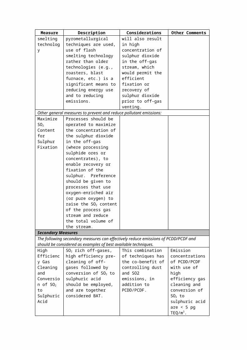
Application Type Typical size range
Fuels Ash Water content
circulating fluidised bed
15MW-100MW
various biomass, d< 10mm
<50% 5%-60%
dust combustor, entrained flow
5MW-10MW various biomass, d < 5 mm
<5% <20%
co-firing a stationary fluidised bed
total 50MW-150MW
various biomass, d< 10mm
<50% 5%-60%
circulating fluidised bed
total 100-300 MW
various biomass, d< 10mm
<50% 5%-60%
cigar burner straw 5 MW-20 MW
straw bales <5% 20%
dust combustor in coal boilers
total 100MW-1 GW
various biomass, d< 2-5 mm
<5% <20%
a Biomass covers typically less than 10% of the total fuel input2.1 Grate furnaces
Grate furnace systems are today the most common combustion technology used for wood wastes and wood residues. According to the technique the wood fuel is moved through the combustion chamber stationary sloping grates, travelling grates and vibrating or moving grates can be distinguished. Grate firing systems are suitable for all types of wood residues and wood waste with particle sizes between 20 and 300 mm. However, fine particles as pulverised wood may be injected through additional burner lances. A major influence on the combustion efficiency, both for travelling grates and vibrating grates, has the fuel and air guidance. Concerning steam generation the furnace design of grate firing systems offers various options for primary emission reduction, e. g. staged combustion or flue gas re-circulation. The investment for grate firing systems depends considerably on the grate technology and flue gas cleaning technology used. Compared to fluidised bed combustion plants in particular for lower capacities the specific investment relative to the total heat input is considerably lower [CSTB 2000].
Figure 1: General scheme of a vibrating grate furnace
232

2.2 Fluidised Bed Combustion
Fluidised bed combustion is utilised for various types of solid fuels. In a typical fluidised bed combustion unit the solid fuel is kept fluidised by injected air together with an inert bed material, in general mainly consisting of limestone or sand and the fuel ash. Nearly exclusively two basic fluidised bed combustion technologies are used for wood combustion. This is atmospheric bubbling fluidised bed combustion (BFBC) and atmospheric circulating fluidised bed combustion (CFBC). Fluidised bed combustion is suitable even for lowest fuel qualities and a great variety of fuels. Regarding wood combustion, nearly all types of wood residues and wood waste can be used. Water contents up to 40 % are possible. Fluidised bed systems are adaptable even to low operation loads. A cycle between low and high loads is in general possible without support fuel and at a rather high speed compared to other combustion technologies. Chlorine induced high temperature corrosion can be suppressed by installing the last superheater unit in the bed. The low combustion temperatures in fluidised bed systems compared to many other combustion technologies offer several operational advantages regarding emission control. The investment for FBC plants is mainly influenced by the FBC technology used and the type of flue gas cleaning installed. CFBC entails a considerably higher specific investment compared to BFBC for plant sizes below 30 MW th. [CSTB 2000]
2.3 Further Combustion Technologies for Wood
Further combustion technologies for wood include underfeed stoker furnaces, cyclone suspension furnaces (muffle suspension furnaces), rotary furnaces, turbulent bottom furnaces, fan blower furnaces as well as dust burners. Underfeed furnaces or underfeed stoker furnaces are in particular suitable for the combustion of dry and not to coarse wood particles with a low ash content. This technique is used for total heat inputs up to 5 MWth. Compared to normal grate furnaces the specific investment is mostly lower. As cyclone suspension furnaces require a dust content of at least 50 % their application is limited in particular to the wood processing industry. Dust burners are used for wood dust with a particle size of up to 1 mm. Applications of this burner type are inter alia wood chip driers and the injection of wood dust in cement furnaces. [CSTB 2000]
232

2.4 Energy Conversion Techniques
For energy conversion downstream wood combustion furnaces heat exchanger systems (boilers) and subsequent systems for combined heat and power production (steam turbines, steam engines etc.) have to be distinguished. Downstream wood combustion furnaces different types of boilers are used according to the heat transfer medium, the plant size, and the energy quality required. Firetube boilers are used for hot water or steam production downstream small-scale and medium-scale wood furnaces. Heat transfer takes only place by convection. Watertube boilers are used for large-scale and medium-scale wood waste combustion plants. The water to be evaporated flows through tubes surrounded by the hot flue gases. Heat transfer takes place predominantly by radiation. Due to the modified construction compared to firetube boilers considerably higher operating pressures up to 100 bar are possible. Downstream wood furnaces in general only heat or combined heat and power is produced. For this reason condensing power generation can be neglectedNevertheless, also combined heat and power (CHP) plants may need condensing capacities in case the heat generated is not used. [CSTB 2000]
2.5 Co-Combustion
Co-combustion means the burning of wood wastes and wood residues together with other waste materials or together with fossil fuels. The objective is to realise synergy effects between two combustion processes. These are either operating costs savings by the use of cheaper secondary fuels, an improvement of the combustion efficiency of the combined process compared to the two processes operated separately, or the possible recovery of the materials introduced in the combustion process as for example the input of fuel ash from secondary fuels in the cement clinker produced in a cement burning process. For wood waste and wood residues the co-combustion and co-gasification processes of major importance are co-combustion in cement furnaces, co-combustion in coal fired power plants, co-gasification with fossil fuels or waste and co-incineration in waste incineration plants. [CSTB 2000]
2.6 Wood Gasification
Gasification of wood and wood waste is the conversion of solid and liquid residues derived from the thermochemical decomposition of the organic matter in the wood at high temperatures in a gaseous fuel by adding oxidising reactants. The main objective of wood gasification is to transfer as much as possible of the chemical energy of the wood feedstock into a gaseous fraction (producer gas) consisting mainly of combustible gaseous products with a low molecular weight. The gasification techniques available are in general distinguished related to the reactor type. The two basic gasification techniques available are fixed bed gasification and fluidised bed gasification. For wood gasification the utilisation of fixed bed gasifiers is in general preferred for smaller total heat inputs below 5 MW th. For larger capacities mostly fluidised bed gasifiers are used. The energy content of the producer gas from gasification can be either used thermally for the firing of a boiler or another thermal process (either separately or by co-combustion e. g. in an existing utility boiler or in a cement furnace) or mechanically for power generation in gas engines or gas turbines. Further possibilities are the utilisation of the producer gas for methanol synthesis or in fuels cells. The system needed for producer gas cleaning is determined by the concentration of impurities and by the requirements of the gas utilisation technique used. Depending on the gas utilisation technique gas cleaning is required to avoid erosion, corrosion, unwanted deposits, and the fulfillment of emission limits. Basically two different gas cleaning concepts, cold (or wet) gas cleaning and hot gas cleaning can be distinguished. Hot gas cleaning is considered as advantageous for advanced high-efficient systems due to the higher achievable electric and overall efficiencies and due to the non-generation of contaminated wastewater and/or condensate. Even though gasification can be seen as proven and reliable technique, for all plants with electricity generation either in gas turbines or gas motors gas cleaning is still a crucial restriction. Technical problems occur inter alia from gas cleaning process control.
232

Concerning cost effectiveness, negative impacts result from gasification residue disposal and high investment and operating costs of the gas cleaning unit itself. [CSTB 2000]
2.7 Combustion of other biomass
Other biomass includes other solid biofuels such as straw and crops and liquid fuels such as rape oil. Straw combustion requires combustion techniques which are not sensitive to the slagging of ashes. Due to the increases input of mineral matter and chlorine there is an increase of dust, HCl and PCDD/PCDF emissions compared to wood combustion [LfU 2002]. Exemplary results from emission tests are given in section 5.2.
3 Emission control measures
Reduction of PCDD/PCDF emissions includes primary and secondary measures which are summarised in Table 2 [Baumbach 2000], [CSTB 2000], [LfU 2002].
Relevant primary measures are similar to the waste incineration sector. Additional flue gas cleaning can be carried out with absorption or adsorption processes. Downstream wood waste combustion in general only adsorption processes are used due to their lower costs. Dry sorbent injection (entrained flow reactor) gained major importance downstream wood combustion due to its technical simplicity and its low costs. As adsorption agent in general a mixture of calciferous substance and activated carbon or lignite activated carbon (activated carbon produced from lignite) is used. Possible calciferous agents are limestone (CaCO3), lime (CaO), and hydrated lime (Ca(OH)2). While the calciferous agents remove SO2, HCl, and HF, the various types of activated carbon minimise heavy metal emissions (Hg, Cd, As), PCDD/PCDF emissions, and emissions of polycyclic aromatic hydrocarbons. A typical mixture used in an entrained flow reactor consists of 85 to 95 % calciferous agent and 5 to 15 % activated carbon. As secondary NOx-emission reduction measure in particular downstream large-scale wood waste combustion installations the SNCR (selective non-catalytic reduction) technique is used. This technique also reduces PCDD/PCDF emissions.
Table 2: PCDD/PCDF emission control measures for biomass firing installations
Management options Emission level (%)
Estimated costs
Management risks
Primary measures: - Control of fuel quality - Optimised burn-out (e.g. reduction of excess air) - Sufficient residence time of flue gases in the hot zone of the furnace
Resulting emission level not quantified
higher fuel priceNo additional cost for new installations
High water content increases PCDD/PCDF formation
Secondary measures:- Efficient dust abatement- Dry sorbent injection- Selective non-catalytic reduction (SNCR)- Selective catalytic reduction (SCR)
Medium efficiencyHigh efficiencyMedium efficiency
High efficiency
Additional investment1):SNCR 50-60 %SCR 110-180 %
Filter temperature < 200 °CDisposal of used sorbents
not common in small plants
not common in biomass combustion plants
1) Percentage related to the investment for furnace, boiler and dust collector of wood combustion plants with 1-10 MW thermal capacity
232
3.1 Fuel characteristics
Fuel quality plays a major role in PCDD/PCDF formation during biomass combustion (see chapter 5.1). PCDD/PCDF are always formed during wood combustion via precursors like phenols and lignin or via de novo reactions in the presence of particulate carbon and chlorine. High levels are expected from burning treated wood (wood waste) in particular in the case of coatings. Wood residues (waste and industrial) often contain various types of contaminants (chromated copper arsenate, PCP, creosote, adhesives, resins, paint and other surface coatings). Another major source of dioxins can be salt-laden wood waste, burned in power boilers, at pulp and paper mills [Lavric 2004].
Combustion of contaminated biomass such as urban wood waste and demolition wood should be strictly limited to installations with efficient flue gas cleaning [Nussbaumer 2003].
The moisture content of biomass can be high. Therefore, dryers may be used prior to combustion. Steam dryers are considered to be safe with low environmental impact. Another method is based on drying with flue gas which is subsequently fed to the stack. In this case emissions of organic compounds such as waxes or aromatic compounds are possible [IPPC 2003].
4 Process Outputs
4.1 Formation of PCDD and PCDF in combustion processes
The dominant reaction for the formation of dioxins and furans in combustion processes is the de novo synthesis. Summarised, the following parameters are responsible for PCDD/PCDF formation [Nussbaumer 1998]:
Temperature for the de novo synthesis: It occurs in the temperature range from approx. 180°C to 500°C and reaches a maximum rate at approx. 300°C.
Chlorine (HCl content; Cl content): Dioxins can also be formed in absence of organic chlorinated compounds. The presence of particulate carbon and a chlorine source is sufficient.
Investigations at a stationary grate combustor have shown that the total amount of PCDD PCDF and coplanar PCB formed was proportional to the chlorine content of the combustion samples when the temperature of the combustion chamber was lower than 700°C. On the other hand, when the grate temperature of the combustion chamber was higher than 800°C, there was only a slight formation of PCDD PCDF and coplanar PCB regardless of the chlorine content of the fuel [Yasuhara 2003].
Unburnt carbon: The amount of PCDD and PCDF on fly ash from municipal solid waste incineration exhibits an almost linear correlation with its carbon content. A tenfold reduction of the residual carbon content in fly ash leads to a similar reduction of the PCDD/PCDF content.
Oxygen content: The dioxin emissions are also influenced by the residual oxygen content in the flue gas. Possible explanations for this effect can be a lower carbon burn our due to a lower temperature in the combustion zone or the influence of oxygen on the oxidation of the dioxin formation catalyst.
Heavy metals (Cu) which act as a catalyst.
The facility size tends to have an influence on the PCDD/PCDF concentration due to better combustion conditions. Tests have shown that even when processing materials containing high halogen quantities, the concentrations remained below those obtained from small facilities using natural wood. When halogenated input materials were added, a very clear relationship between CO and PCDD/ PCDF concentrations was observed. The dominant influence of combustion quality on PCDD/PCDF emission concentrations could be seen from the increasing CO concentrations and simultaneously decreasing flue gas temperature [Lavric 2004].
232

4.2 Emissions of PCDD/PCDF
The influence of fuel quality and combustion conditions on PCDD/PCDF emissions shall be illustrated by the tables below.
Table 3 gives an overview of emission values observed for different types of wood fuel burned in industrial furnaces.
Table 3: PCDD/PCDF concentrations for different types of wood fuels [Buwal 2004]
Type of wood PCDD/PCDF min.ng I-TEQ/m³ (at 11% O2)
PCDD/PCDF max.ng I-TEQ/m³ (at 11% O2)
Lump wood (natural] 0.02 0.13
Wood chips (natural) 0.004 0.88
Wood waste 0.03 18.0
Chlorine / heavy metal free particle board
0.03 0.10
Particle board with PVC or NH4Cl 0.05 12.28
Particle board with PCP 0.21 5.14
Tests at an installation with ceramic filter and SCR showed significant dioxin formation in the filter at a temperature of 300°C as well as the degree of dioxin destruction in the subsequent catalyst (see Table 4). These tests also show that concentrations in the raw gas from natural wood combustion remain below 0.1 ng/Nm3 without any further treatment. Wood waste can increase emissions of the same installation by a factor of 20 [Buwal 2004].
Table 4: Test results of an installation with ceramic filter and SCR
Unit ( at 11% O2)
Wood Particle board Waste wood
PCDD/PCDF in raw gas ng TE/Nm3 0.083 0.095 17.76
PCDD/PCDF after filter ng TE/Nm3 0.836 2.947 78.25
PCDD/PCDF in clean gas ng TE/Nm3 0.052 0.189 8.18
Temperature ceramic filter °C 330 300 300
Temperature catalyst °C 240 230 230
Launhardt and Thoma tested various herbaceous biofuels (straw, whole plant cereals and set aside hay) and spruce wood for their potential to form PCDD/F, polychlorinated phenols (PCPh), polychlorinated benzenes (PCBz) and PAH during combustion. The trials were conducted in an automatically charged multi-fuel furnace for domestic applications of 50 kWth. Relatively uniform combustion conditions were indicated by the CO-emission results. Flue gas and different ash fractions were analyzed. The concentration of dioxins was in the range of 0.052 – 0.891 ng I-TEQ/Nm3 at 13% O2 (Table 5). All the emissions from wood were at a relatively low level. Increased emissions, between 10 and 25 times higher, of PCDD/F, PCPh and PCBz, were detected when herbaceous fuels were used [Lavric 2004].
232

Table 5: PCDD/PCDF emissions from different types of biomass [LfU 2002]
Fuel type PCDD/PCDF ng I-TEQ/m³
Wood (spruce) 0.052
Straw (wheat) 0.656
Hay 0.891
Triticale 0.052
Rape pellets 0.245
PCDD/PCDF emission data for liquid biomass combustion are scarce. Tests at a rape oil motor for combined heat and power production (90 kW thermal power) showed PCDD/PCDF concentrations of 4-7 pg TEQ/m3. PCB concentrations amounted to 40-81 ng/m3 [LfU 2002].
A comprehensive review of PCDD/PCDF test results from wood-fired installations can be found in [Lavric 2004].
For biomass-fired plants, in particular wood-fired installations, an emission level of 0.1 ng I-TEQ/m3 is generally regarded as achievable [IPPC 2003].
4.3 Other releases of PCDD/PCDF
PCDD/PCDF are discharged with solid combustion residues such as bottom ashes and fly ash. In general, PCDD/PCDF concentrations increase with decreasing particle size [LfU 2002]. Therefore, pollutant concentrations in fly ash tend to be higher than in bottom ash:
Pohlandt and Marutzky analysed furnace, boiler and fly ash. The samples were collected at different plants in the wood working industry, from a smoke house and from combustion of wood impregnated with inorganic wood preservative consisting of boron, chromium and copper in a two-stage laboratory furnace. They found that the fly ashes exhibit the highest levels of PCDD/PCDF. The concentrations of PCDD/PCDFF in the ashes originating from the impregnated wood were higher than those of the ashes from the combustion of the diluted impregnated wood, but below those determined for the fly ash of industrial wood firing plants. The concentration of dioxins in the fly ash is higher than in the bottom ash. This observation was confirmed by Wunderli et al. and Yamamura et al. [Lavric 2004].
In particular in the case of wood waste combustion captured fly ash has to be disposed of in an environmentally sound manner.
The fly ash from straw combustion units is disposed of primarily due to its high content of cadmium. The bottom ash is normally bought back to the fields or used as a road construction material [IPPC 2003].
5 Best Available Techniques (BAT) and Best Environmental Practices (BEP) for firing installations for wood and other biomass
Firing installations shall achieve PCDD/PCDF emission levels below 0.1 ng I-TEQ/m3 (at 11 % O2).
5.1 Primary measures and process optimization to reduce PCDD/PCDF
[Nussbaumer 1998] Prevention of illegal incineration:
Utilization of urban waste wood in conventional combustion systems has to be strictly avoided.
232

Optimized combustion technology: Improved burn out of gases and fly ash and reduction of dust content:
- Reduction of excess air ratio to < 1.5 – 2;
- Good mixing quality of gas and air (high turbulence);
- Sufficient residence time in the hot zone;
- Minimal disturbance of the glow bed and homogenous distribution of the primary air;
- Optional integration of SNCR for NOx reduction.
Measures in the boiler:
- Minimal residence time in the temperature range between 180°C and 500°C and minimal dust deposition ability.
Optimized plant operation:
- Application of advanced combustion control technologies to ensure optimal burn out in practice.
- Stationary operation, no on/off operation and prevention of rapid changes of heat the demand.
5.2 Secondary measures
Optimized gas cleaning:
- Prevention of the temperature window of the de novo synthesis in filters (filter temperature < 120°C);
- PCDD/PCDF separation in dust separators (electrostatic precipitators, fabric filters) in combination with sorbent injection (if necessary);
Optional destruction of PCDD/PCDF by catalytic oxidation, i.e. in combination with SCR for NOx reduction.
6 Performance Monitoring and Reporting
PCDD/PCDF emissions shall be monitored in accordance with international standard methods.
In order to ensure complete combustion furnaces shall be equipped with measuring instruments which continuously determine carbon monoxide emission mass concentrations.
In order to ensure the performance of emission control equipment, furnaces shall be equipped with measuring instruments which continuously determine dust emission mass concentrations qualitatively or quantitatively (depending on plant size).
In addition, quality control procedures shall be implemented with regard to fuel composition.
7 References
[Baumbach 2000] Zuberbühler, U; Baumbach, G.: Entwicklung eines Feuerungskonzeptes zur Verbesserung des Ausbrandes bei gleichzeitiger NOx-Minderung bei der Holzverbrennung im gewerblichen Bereich; Institut für Verfahrenstechnik und Dampfkesselwesen IVD; University of Stuttgart; Report BWPLUS 3 96 007; Forschungszentrum Karlsruhe (2000)
[Buwal 2004] Nussbaumer, T.: Dioxin- und PAK-Emissionen der privaten Abfallverbrennung; UMWELT-MATERIALIEN NR. 172 Luft; Bundesamt für Umwelt, Wald und Landschaft BUWAL, Bern, 2004
232

[CSTB 2000] CSTB, Quasco, CTBA, La Calade and DFIU/IFARE: Energy-Efficient Technologies from Demolition, Packaging and Industrial Wood Waste; Programme THERMIE, Type B action (n°STR-1965-98-FR); Final report Phase I (2000)
[IEA Bioenergy] IEA Bioenergy: Biomass Combustion and Co-firing: An Overview; IEA Bioenergy Task 32; www.ieabioenergy-task32.com
[IPPC 2003] European Commission: Integrated Pollution Prevention and Control (IPPC) Draft Reference Document on Best Available Techniques for Large Combustion Plants; March 2003
[Lavric 2004] Lavric, E. D.; Konnov, A. A.; De Ruyck, J. : Dioxin levels in wood combustion – a review; Biomass and Bioenergy 26 (2004) 115 – 145
[LfU 2002] Bayerisches Landesamt für Umweltschutz: Energetische Nutzung nachwachsender Rohstoffe: Zusammenfassender Bericht zu 15 Teilprojekten (2002)
232

F . C H E M I C A L P R O D U C T I O N P R O C E S S E S
1 Process Description
1.1 Introduction to Organic Chemical Processes.
This paper focuses on processes for the manufacture of large-volume industrial chemicals which could theoretically give rise to by-product POPs. Chlorination processes are used in synthesis of hundreds of industrial and specialty chemicals.1 Chlorine chemistry is also used in processes where the final product contains no chlorine atoms. Under modern conditions of operation, however, these processes are typically not a major source of emission of by-product POPs.2,3
Many of the general principles developed here can also be applied to the much larger number of manufacturing processes used to produce a wide range of fine (low-volume specialty) chemicals, including pesticides and pharmaceuticals. Production of such chemicals depends on the unique properties of chlorine that make it a valuable synthetic tool.
A list of some of the processes leading to industrial chemicals is included in Appendix A.1 It is beyond the scope of this paper to attempt to define BAT/BEP for each of these processes individually; rather, the processes will be examined for what they have in common and how those common practices can be addressed by BAT/BEP to reduce the formation and particularly the release of by-product POPs.
Figure 1. General Process overview

GUIDELINES ON BAT AND GUIDANCE ON BEP DRAFT 29/07/04
Figure 2. C1 and C2 processes.1
249
Cl2
Cl2
CCl2=CCl2Tetrachloroethylene
HCl, Al2O3Methanol
CCl4Carbon tetrachloride
CH2Cl2
Methylene chloride
CH3ClMethyl Chloride
CHCl3Chloroform
MethaneHeat or Light
Cl2
Cl2
Cl2
CCl2=CCl2
TetrachloroethyleneCHCl=CCl2
Trichloroethylene
CH2=CCl2Vinylidene Chloride
1,1,1,2- and 1,1,2,2Tetrachloroethane
& Pentachloroethane
425º C
CH2=CHClVinyl Chloride
CH3CHCl21,1-Dichloroethane
400º C
HCl, FeCl3
50º C
CH3CCl3
1,1,1-Trichloroethane
CH2ClCHCl21,1,2-Trichloroethane
Cl2
Cl2
HeatNaOH or
LimeHCl, FeCl3
CH2=CH2
Ethylene
CH2ClCH2Cl1,2-Dichloroethane
(Ethylene Dichloride)
CH2CH2ClEthyl Chloride
HCl, AlCl3 Cl2, FeCl3
HCl, O2, Cat(Oxychlorination)
Excess Cl2,Heat
50º C

GUIDELINES ON BAT AND GUIDANCE ON BEP DRAFT 29/07/04
Most of the processes involve a hydrocarbon, saturated or unsaturated, treated with elemental chlorine and in most processes also a catalyst. Reactions can be electrophilic additions to olefins, chlorination of aromatics, or homolytic cleavage of carbon-hydrogen bonds with subsequent formation of the aliphatic chloride. In many cases, chlorine atoms are present in the final product; on the other hand, in some processes (addition of an alcohol or amine to phosgene to produce, for example, polycarbonate and polyurethane plastics) no chlorine atoms are present in the final product. In addition, most of the processes involve generation of HCl as a co-product, via dehydrohalogenation or free radical reaction of chlorine with aliphatic hydrogen (Figure 1).
Crude products of these reactions vary in overall yield and purity, and as with virtually all industrial chemical processes, purification of the final product is required prior to sale or further internal use. Purification can involve separation of a mixture of salable products—in many cases a spectrum of useful products results from a single reaction treatment--or separation of salable products from the inevitable formation of high molecular weight side products. For most organics and some inorganics that purification step involves distillation.
Generally, high molecular weight side products are not salable as themselves. In some cases they are thermally oxidized, with HCl, CO and CO2 as products of this oxidation. HCl is recovered and reused as an integral part of the process. In some cases they are viewed as wastes to be destroyed, usually by hazardous waste combustion, still, HCl recycling is common.
1.2 Co-Product Hydrogen Chloride.
HCl is handled in one or more of the following ways. It can simply be neutralized and discharged as salt (sodium chloride). However, in some processes HCl can constitute a large amount of the effective use of input chlorine, so neutralization and discharge carries with it a large opportunity cost in the loss of potential raw material.
HCl can be recovered, hydrated and then sold as the commercial product muriatic (hydrochloric) acid or used for pH adjustment in chloralkali cells. Thus, there is some recycling of HCl electrolytically to chlorine. Muriatic acid in the US has been analyzed for PCDD/F and found to contain ca. 20 pg I-TEQ/L range (0.004 g I-TEQ/yr for US production).4
HCl can also be dried, oxidized catalytically and in the presence of organic raw material, reacted as elemental chlorine to generate more of the desired product. The process by which this is accomplished is called oxychlorination and often constitutes a valuable means of in-process recycling to avoid waste of valuable chlorine feedstock.
1.3 Direct Chlorination.
Free radical addition of chlorine to aliphatic hydrocarbons, typically methane, and direct electrophilic addition of a halogen to an alkene are well-known from basic organic chemistry. As utilized in industry, the former is catalyzed by light and the latter is typically a low–temperature operation catalyzed by FeCl3 .5 In the former, a free radical mechanism is desired. On the other hand, in the latter, unproductive side reactions result from free radicals which can be inhibited with low concentrations of oxygen.
There is little if any potential for formation of byproduct POPs in direct chlorination processes of aliphatic hydrocarbons. Aromatic feedstocks can also be chlorinated directly under mediation of a Lewis acid catalyst. The presence of aromatic chlorides as products of the process leaves open the possibility for POPs generation under some conditions.
1.4 Oxychlorination.
In oxychlorination, an organic such as ethylene reacts with dry HCl and either air or pure oxygen in a heterogeneous catalytic reaction. An example is the reaction involving HCl, oxygen and ethylene to form ethylene dichloride (EDC) and water.
249232

GUIDELINES ON BAT AND GUIDANCE ON BEP DRAFT 29/07/04
C2H4 + 2HCl + ½O2 C2H4Cl2 + H2O
While there are many different commercial oxychlorination processes, in each case the reaction is carried out in the vapor phase over a modified Deacon catalyst. Unlike the Deacon process (which uses air or oxygen to oxidize HCl to Cl2 and H2O under heat and catalysis) oxychlorination of ethylene occurs readily at temperatures well below those required for HCl oxidation per se. The catalyst typically contains cupric chloride (CuCl2) as the primary active ingredient, impregnated on a porous support such as alumina, and may also contain numerous other additives.
The oxychlorination reaction generates heat and thus requires cooling for temperature control, which is essential for efficient production of EDC. While there is an effective minimum temperature for the reactions, excessively higher reactor temperatures lead to more by-products, mainly through increased ethylene oxidation to carbon oxides and increased EDC cracking. Cracking of EDC yields vinyl chloride monomer (VCM) and subsequent oxychlorination and cracking steps can lead progressively to higher molecular weight by-products with higher levels of chlorine substitution. Excessive temperatures (>300°C) can also deactivate the catalyst through increased sublimation of CuCl2. There is a strong commercial incentive to avoid those reaction conditions (overheating) that have the potential to lead to the production of polychlorinated by-products.
There are two types of catalyst systems used in oxychlorination: fixed bed and fluid bed. Both can be considered BAT.6
1.4.1 Fixed Bed Oxychlorination.
Fixed bed reactors resemble multi-tube heat exchangers, with the catalyst packed in vertical tubes held in a tubesheet at top and bottom. Uniform packing of catalyst within the tubes is important to ensure uniform pressure drop, flow, and residence time through each tube. Reaction heat is removed by generating steam on the shell side of the reactor, or by flowing some other heat transfer fluid through it.
Temperature control in these reactions is important. The tendency to develop hot spots in a fixed bed can be minimized by packing the reactor tubes with active catalyst and inert diluent mixtures in proportions that vary along the length of the tubes, so that there is low catalyst activity at the inlet, but the activity steadily increases to a maximum at the outlet.
Alternatively, tubes can be packed with catalyst formulated to have an activity gradient along the length of the tubes. Multiple reactors in series can also be used in fixed bed oxychlorination, providing a similar activity gradient. Staging the air or oxygen feed and grading the catalyst activity flatten the temperature profile and allow improved temperature control.7
1.4.2 Fluid Bed Oxychlorination.
Fluid bed oxychlorination reactors are typically vertical cylindrical vessels equipped with a support grid and feed sparger system designed to provide good fluidization and feed distribution. They contain internal cooling coils for heat removal, and use either internal or external cyclones to minimize catalyst carryover. Fluidization of the catalyst assures intimate contact between feed and product vapors, catalyst, and heat transfer surfaces, and results in a uniform temperature within the reactor. Reaction heat is removed by generating steam within the cooling coils or by passing some other heat transfer medium through them.
Operating temperature of 220-245°C and gauge pressure of 150-500 kPa (22-73 psig) are typical for oxychlorination with a fluid bed reactor. Fixed bed oxychlorination generally operates at higher temperatures (230-300°C) and gauge pressures of 150-1400 kPa (22-203 psig). Chlorinated by-products of ethylene oxychlorination typically include 1,1,2-trichloroethane, chloroform, carbon tetrachloride, ethyl chloride, chloral, 2-chloroethanol, all of the chloroethylene congeners, and higher boiling compounds.
249232

GUIDELINES ON BAT AND GUIDANCE ON BEP DRAFT 29/07/04
Figure 3. Oxychlorination Flow Diagram 8
products that will either be sold or used in subsequent process steps. In virtually all cases, organic
1.5 Main Product Isolation.
Another common facet of these processes is the need to purifyreaction products will be distilled. Fractional distillation separates streams of desired products and also desired product from unwanted high molecular weight materials called “heavy ends” or tars.
In the European Union the Integrated Pollution Prevention and Control (IPPC) Directive requires the use of Best Available Techniques (BAT) in generating a plant permit. To facilitate this, BAT Reference Documents (BREFs) are produced under the Directive by the European Integrated Pollution Prevention and Control Bureau (EIPPCB). Several of these are relevant to the application of BAT to processes using chlorination. For example, the BREF relating to Large Volume Chemical Processes produced under the IPPC Directive contains discussion of distillation.6
Distillation is a standard engineering unit operation. It is based on sequential vaporization and condensation of liquid in a column which typically includes packing or trays so as to maximize its internal surface area. Vapor that reaches the top of the column is enriched in the lowest boiling material present in the distillation mixture.
249232

GUIDELINES ON BAT AND GUIDANCE ON BEP DRAFT 29/07/04
Design and operation of distillation units is well-understood both in separations theory and in practice. For non-azeotroping materials with widely separated boiling points—for example, vinyl chloride and PCDD/F--virtually complete separations can be accomplished in a well-designed and operated column.9
Desired materials are isolated and transported as liquids. For materials with boiling points above ambient temperature (example: EDC) closed but not pressurized containers are used. For materials with boiling point below ambient temperature (example: VCM, chlorine) pressurized containers are used.
1.6 By-product Destruction.
Undesired materials, including heavy ends are destroyed in thermal processes, with or without oxygen. Figure 4 shows a prototypical heavy ends destruction train with HCl recovery.
When there are air, water and solid emissions from this process, these streams can be analyzed and treated for by-product POPs contamination. Under the IPPC Directive, BREFs for waste combustion and treatment of water and gas outputs from these kinds of processes are being developed, although treatment systems are well-defined by regulation in many countries. Other BAT-BEP guidance documents for municipal and hazardous waste contain similar treatment descriptions.
In general, BAT for air streams can involve recovery and recycle of HCl, combustion of trace volatiles, scrubbing of incinerator output streams with water, alkaline solutions or dry alkali, addition of activated carbon and baghouses for removal of particulate. These may be used alone or in combination. Treatment of water streams can involve stripping and recovery (condensation or absorption) of volatile materials from water.
Subsequent biological purification of water streams with removal of solids is done in a dedicated water treatment system. BAT for both streams will be considered in the granting of permits for facilities combusting heavy ends.
1.7 Summary: What Organic Processes Have In Common.
Figure 5 summarizes generically many of the processes described, including chlorination of organic or inorganic raw materials, purification of the products, separation of streams for recycle (HCl, Medium Boilers), destruction of side-products (Organic High Boilers) and sale of products (Low Boilers, HCl, End Products).
249232

GUIDELINES ON BAT AND GUIDANCE ON BEP DRAFT 29/07/04
Figure 4. By-Product Destruction
Figure 5. Block Diagram of Generic Organic Process
1.8 Introduction to Inorganic Chemical Processes. Chlorine is used in generating inorganics whether it remains in the final product (NaOCl, ClO2, FeCl3, AlCl3, ZnCl2, etc.) or is simply used in the process (TiO2, Si). These inorganic compounds may be used either stoichiometrically
249232

GUIDELINES ON BAT AND GUIDANCE ON BEP DRAFT 29/07/04
(NaOCl, ClO2) or as catalysts (FeCl3, AlCl3, ZnCl2, etc). Thus far, the only inorganic chemical manufacturing process identified with production of by-product POPs is manufacture of TiO2 by the chloride process; however, other metal carbochlorination processes for purification of ore may involve similar conditions to that of TiO2 processing.
1.8 Titanium Dioxide.
There are two processes for manufacture of TiO2: the chloride process and the sulfate process. They present an interesting case study: the former produces much less waste but under some circumstances can give rise to POPs. The latter involves much more non-POPs waste.
The chloride process has grown in use over the past thirty years as a result of its relative compactness, recycling of process materials, better product properties and considerably lower generation of waste. TiO2 ore such as rutile or ilmenite -- containing other metal oxides--is chlorinated under high temperature to produce TiCl4, a stable, distillable liquid. Other metal halides are removed after cooling. TiCl4 is then purified and oxidized with O2, liberating chlorine, which is recycled in the process. This oxidation process is thermodynamically favored at temperatures above 600○
C. A generalized overview of the chloride process is shown in Figure 6 and a more complete description of the competing sulfate process is found in Section 3.1
Figure 6. Chloride Process for Manufacturing Titanium Dioxide.
249232

GUIDELINES ON BAT AND GUIDANCE ON BEP DRAFT 29/07/04
2 Potential Sources of Unintentionally Produced POPs.
2.1 Oxychlorination Process.
The presence of heat, elemental chlorine, copper chloride catalyst and organic material makes the oxychlorination process a potential source of by-product POPs. Aromatics may be generated in high temperature processes and may also be present in feed materials, including HCl or air. Conditions in an oxychlorination reactor are in some ways similar to conditions in the areas of an incinerator downstream of the combustion zone, but may or may not contain similar amounts of soot-like elemental carbon or PAH’s, which may contribute to de novo formation of PCDFs.10,11 By-product POPs created in this process, however, can be virtually completely removed from product and isolated in high-boiling materials (heavy ends) as a result of the distillation process.
Some by-product POPs will adhere to particles of catalyst. In the case of fixed bed systems, they can be a part of the spent catalyst that is removed from service. This material can be treated thermally to destroy adsorbed organics or placed in a secure landfill. In reactors, fluidized bed catalyst particles undergo size attrition and can become entrained in the vapor stream. These particles eventually show up in solid waste or in the biological solids removed at the end of water treatment.
2.1.1 Acetylene Process for Vinyl Chloride.
Use of the balanced process for production of EDC, and subsequent cracking to vinyl chloride has, over the past 50 years, largely—but not entirely--superseded production of vinyl chloride via the acetylene route. In the acetylene process, calcium oxide and carbon are strongly heated together to produce calcium carbide. When CaC2 is reacted with water, acetylene is produced. Vinyl chloride results from catalyst-mediated addition of HCl to acetylene. Due to the decreasing use of this process in the days of well-defined analytical procedures for detection of POPs, little is known of POPs generation and concentration in materials and wastes.
2.2 Other Process Contact with Elemental Chlorine.
There is anecdotal evidence that contact of elemental chlorine with organic process equipment (seals, gaskets, fiberglas equipment) which may contain aromatics, PAHs or elemental carbon can give rise to by-product POPs, usually PCDFs. In certain processes where high boiling material or condensate is separated from manufactured elemental chlorine and not recycled in the process, by-product POPs can be found in solid or liquid effluent.
2.3 Titanium Dioxide.
The presence of coke, chlorine, metals and elevated temperature may give rise to dioxins and furans analogous to those generated in oxychlorination. PCDD/F, if formed, are expected to partition into stream(s) containing residual coke.
2.4 By-Product Destruction.
There are three types of waste treatment: Hazardous Waste Combustion, Thermal Oxidation and Catalytic Oxidation, and some detail on each is presented in the EDC/VCM Chapter of the EIPPCB BREF on Large Volume Organics.6 When heavy ends are burned, some by-product POPs are generated as in any hazardous waste combustion. EIPPCB is in the process of generating a BREF on waste combustion processes; however, there are legal requirements and best available technologies already in use in the US, the EU and Japan among others.
The Catoxid®12 process is a fluidized-bed catalytic process for oxidation of organics. It generates a stream of HCl and CO2 that is sent in totality to the oxychlorination reactor for internal recycle.
2.5 Products.
Many products of these processes have been analyzed for by-product POPs, especially PCDD/F. In general, products of the chloralkali-through-vinyl chloride chain are very low in such contamination; however, for these and other products the POPs concentration may be a function of the efficiency of distillation or other purification.
249232

GUIDELINES ON BAT AND GUIDANCE ON BEP DRAFT 29/07/04
3 Alternate Processes to Chlorination.
3.1 Titanium Dioxide, Sulfate Process.
For TiO2, there is an alternate commercial process utilizing sulfuric acid instead of chlorine.
In the sulfate process for TiO2 ore is dried, ground, and classified to ensure efficient sulfation by agitation with concentrated sulfuric acid in a batch or continuous exothermic digestion reaction. Controlled conditions maximize conversion of TiO2 to water-soluble titanyl sulfate using the minimum acid. The resultant dry, green-brown cake of metal sulfates is dissolved in water or weak acid, and the solution treated to ensure that only ferrous-state iron is present. The solution temperature is reduced to avoid premature hydrolysis and clarified by settling and chemical flocculation. The clear solution is then further cooled to crystallize coarse ferrous sulfate heptahydrate (known as "copperas", FeSO4.7H2O) which is separated from the process and sold as a by-product.
The insoluble "mud" is washed to recover titanyl sulfate liquor. That liquid is filtered to remove final insoluble impurities, then evaporated to a precise composition. Hydrolysis to produce a suspension ("pulp") consisting predominantly of clusters of colloidal hydrous titanium oxide follows.
Precipitation is carefully controlled to achieve the necessary particle size, usually employing a seeding or nucleating technique. The pulp is then separated from the mother liquor and extensively washed to remove residual traces of metallic impurities, using chelating agents if necessary. The washed pulp is treated with chemicals which adjust the physical texture and act as catalysts in the calcination step. This process can produce either anatase or rutile crystal forms depending on additives used prior to calcination.13
Waste generation is far less in the chloride process, but the chloride process may give rise to small amounts of by-product POPs. Waste generation in the sulfate process, including sulfuric acid and other mineral waste can be 10-20 times higher, but is not known to involve by-product POPs. Trading elimination of small amounts of by-product POPs for generation of large quantities of other waste materials may not be the optimal environmental approach. BAT can be plant specific and viewed on a case-by-case basis.
4 Primary and Secondary Measures
4.1 Primary Measures of Greater Impact
4.1.1 Distillation and Internal Recycling of By-products.
Distillation is used primarily to produce product of purity appropriate to downstream processing. As an example, VCM is manufactured via oxychlorination and purified by distillation. Rigorous distillation is used due to the potential for disruption of subsequent polymerization process by impurities. Unsaturated materials that might act as co-monomers competing in the polymerization and saturated or aromatic materials susceptible to free radical reactions other than polymerization can negatively impact polymerization reaction kinetics.
Distillation and high purity are important for good production. Distillation systems can be designed to effect separation of materials of closely- or widely-separated boiling points. The boiling points of chemical products of direct chlorination and the boiling points of competing impurities allow for their practical separation. Their boiling points are also sufficiently different from those of the unintended POPs, however, that virtually complete separation can be accomplished. The Large Volume Organic BREF notes that purified EDC does not contain significant amounts of PCDD/F.6
Destruction of chlorinated by-product materials allows for HCl to be harvested and reused.14 This is deemed “greater impact” because small changes in POPs generation upstream of distillation are not reflected in the quality of desired products after distillation.
249232
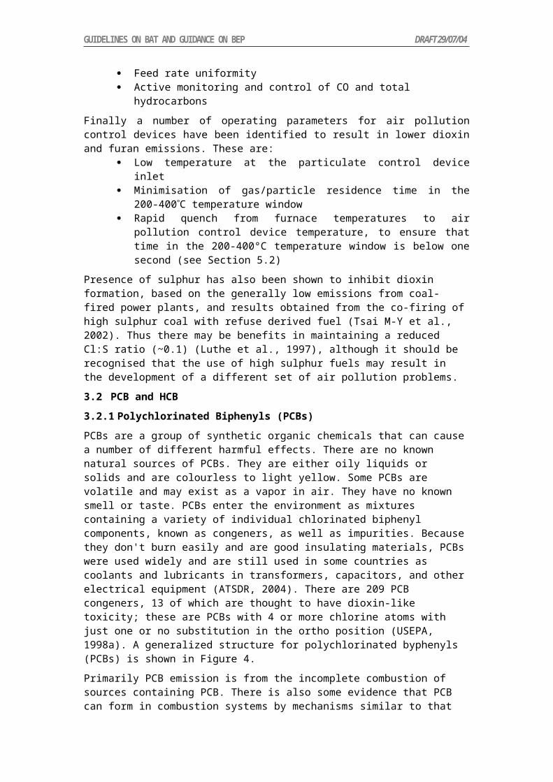
GUIDELINES ON BAT AND GUIDANCE ON BEP DRAFT 29/07/04
Distillation as a means of separating desired product from inadvertent side products is used across the chemical production industry from commodities to pesticides. Adapting the design and operation of distillation apparatus is, in principle, relatively straightforward. Residual side product contained in commercial product can be minimized by appropriate design and operation. Effecting more complete separation for materials with boiling points that are not so widely separated as, for example, those of vinyl chloride and the various lower molecular weight side products is for the most part a matter of correct design and construction and operation cost. Differences in concentration of residual by-product POPs in commercial product may be due to differences in local regulation of products.
4.1.2 Elimination of Carbon Electrodes for Chloralkali Production.
Older technology in the manufacture of chlorine and caustic soda utilized graphite anodes. Residues found from cells so constructed contained significant amounts of PCDD and especially PCDF.2 This problem was eliminated following the invention of the coated titanium anode by H. B. Beer in 1965 and subsequent substitution for graphite in these processes.15 The use of graphite electrodes does not constitute BAT.
4.1.3 Elimination of Alkali Treatment of 1,2,4,5-Tetrachlorophenol and 2,4,5-Trichlorophenol.
Manufacture of 2,4,5-Trichlorophenol was accomplished by alkali treatment of 1,2,4,5-tetrachlorobenzene. This chlorinated phenol, in the presence of excess alkali, could generate significant amounts of side-product TCDD. This process does not constitute BAT.
4.1.4 Elimination of Phenol Route to Chloranil.
This process is described in the Toolkit.2 Chloranil (2,3,5,6-tetrachloro-2,5-cyclohexadiene-1,4-dione) is the precursor for production of dioxazine dyes. When prepared by chlorination of phenol or aniline via elemental chlorine, significant amounts of PCDD/F are generated as by-products. This process does not constitute BAT. Chlorination of hydroquinone by HCl generates much cleaner product.
4.1.5 Modified Production of Pentachlorophenol (PCP) and Sodium Pentachlorophenate.
The following processes are also described in the Toolkit.2 Three routes to PCP are known commercially. Chlorination of phenol by Cl2 over a catalyst, hydrolysis of hexachlorobenzene (HCB) with sodium hydroxide and thermolysis of HCB. The most common route today is the first. Sodium pentachlorophenate can be produced via hydrolysis of HCB, or more commonly, by treatment of PCP by sodium hydroxide.
For both products, careful control of reaction conditions (e.g., temperature, chlorine feed rate and purity of catalyst) leads to significant reductions of dioxin microcontaminants. In the US, emission of these materials was reduced from ca 3-4 mg I-TEQ/kg in the mid- to late-1980s to ca 1 mg I-TEQ/kg in the years since 1988.3
Facilities utilizing products manufactured in the processes named above should also examine the need for secondary measures of their own, especially BAT waste disposal practices.
4.2 Primary Measures of Lesser Impact
4.2.1 Use of Hydrogen in Oxychlorination.
Oxychlorination process feed purity can contribute to by-product formation, although the problem usually is only with the low levels of acetylene which are normally present in HCl from the EDC cracking process. Acetylene fed to the oxychlorination reactor could, in principle be converted to highly chlorinated C2 products, and chlorinated C2 products can give rise to chlorinated aromatics via cyclotrimerization.11,16 Selective hydrogenation of this acetylene to ethylene and ethane in a reactor prior to the oxychlorination reaction is widely used as a measure to avoid side product synthesis, especially of polychlorinated aliphatics (See Figure 2).
249232

GUIDELINES ON BAT AND GUIDANCE ON BEP DRAFT 29/07/04
4.2.2 Catalyst Maintenance and Temperature Uniformity Control.
Fluidized-bed reactors tend to have better temperature control, and more uniform performance, although the previously mentioned attrition of catalyst particles can allow for carryover into other streams within the facility. For fixed-bed oxychlorination catalysts appropriate packing and maintenance can reduce hot spots and potentially can both reduce fouling of the catalyst bed, loss of productivity and the potential for generation of high molecular weight products. Catalyst beds are changed on a regular basis to maintain efficiency.
4.2.3 Reduction in Aromatic Hydrocarbons in Feeds to Oxychlorination Processes.
Two patents specify pretreatment of air17 or HCl18 reagents used in oxychlorination to remove aromatics, presumably precursors to various POPs. This patented technology is proprietary and as such may not be appropriate for any required BAT implementation, but indicates another primary approach.
4.3 Secondary Measures
4.3.1 BAT for Waste Disposal Practices.
Since all or nearly all POPs by-products are isolated in the by-product stream, practice of BAT in destruction of these by-products, including the combustion step, is critical for POPs minimization. Combustion technology has been developed that discriminates against generation of POPs. In addition to prevention of formation, treatment of gases prior to release reduces emissions of POPs.
Figure 7. Schematic of Downstream Treatment of Combustion Products.
In the US, Europe and Japan there are specified technologies for treatment of flue gas, waste water and waste solids from combustion processes. For flue gas they involve, among others, rapid cooling or neutralization, addition of activated carbon and removal of solids via properly designed baghouses or electrostatic precipitators. For waste water, they involve, among other processes, neutralization, settling ponds and biological treatment. Waste solids may be deposited in a secure landfill or in some cases used as filler in products such as asphalt or concrete.
The EU BREFs and Stockholm Convention BAT for Hazardous Waste Combustion and downstream treatment of gas, liquid and solid wastes are useful here as the processes are fairly well-known and generic. When these techniques are practiced, emission of by-product POPs is virtually eliminated.
5 Summary of Measures.
Modify processes to reduce generation of by-product POPs. Incorporate steps that treat impurities in raw materials, and use rigorous operational maintenance. Purify products by distillation. Internally recycle inadvertently generated high molecular weight side-products as an integral part of the process.
249232

GUIDELINES ON BAT AND GUIDANCE ON BEP DRAFT 29/07/04
6 Performance Standards.
Performance standards can be set locally in individual plant permits, and will vary. By-product PCDD/F emission is mentioned in the ECVM Charter, and reflected in the OSPAR process via Decision 98/4 and adoption of BAT via PARCOM Recommendation 96/2. That standard is 1 μg TEQ/ton oxychlorination capacity release to water. Air emission limits in the ECVM Charter are 0.1 ng TEQ/Nm.3.19 This limit corresponds to the EU regulatory limit for emissions of PCDD/F to air from incinerators. Limits in other regions/countries will typically be congruent with hazardous waste combustor regulations in local areas.
7 Performance Measures.
These may include: analytical chemistry on emission streams and in some areas, reporting of POPs to a Pollutant Release and Transfer Registry (PRTR), such as the Toxics Release Inventory in the US.20,21
Appendix A: Synthesis of commodity chemicalsChemical Process Process Use Co-Products
Chlorine, Caustic soda NaCl + H2O==> Cl2 + NaOH + H2 More Common
See EIPPCB BREF, Expert Group presentation
Organics
Allyl chloride Direct chlorination of propylene >300 deg C;
More Common
HCl
Pyrolysis of 1,2-dichloropropane Less Common Chlorinated olefins, HCl
Chloranil dye See toolkit
Chloroprene (2-chloro-1,3-butadiene)
C2H2 + CuCl/NH4Cl==>vinyl acetylene + HCl==> chloroprene
Less Common
Vapor phase Butadiene + Cl2 ==> 1,4 & 3,4 dichloro; isomerized (Cu catalyst) to 3,4 dichloro; -HCl via NaOH; distilled to separate low boiling mono-Cls; 3,4-di; 1,4-di; heavies
More Common
NaCl; overchlorinated products
Chlorinated benzenes Vapor phase: Benzene + Chlorine + HCl Less Common Mixed product
Liquid phase: Cl2/FeCl3 to yield mix; controlled by amount of chlorinating agent (monos) some other specialized processes for certain isomers; high Cl materials can precipitate. Purified by distillation and crystallization; separations difficult.
More Common
HCl
Epichlorohydrin Allyl chloride + HOCl (chlorine water) ==> glycerol chlorohydrins + NaOH/(CaOH)2==>epichlorohydrin;
More Common
Hydrolyzed product; polymers
249232

GUIDELINES ON BAT AND GUIDANCE ON BEP DRAFT 29/07/04
Chemical Process Process Use Co-Products
Steam stripped then distilled.
Also: propylene +O2, (Pd catalyst) ==> allyl acetate==>allyl alcohol + Cl2 ==> allyl chloride
Isocyanurate disinfectants
Isocyanuric acid + NaOH + Cl2
Phosgene CO + Cl2 used virtually immediately to produce polycarbonate and polyurethane
Chlorinated Phenols Lesser chlorinated Phenols: phenol + Cl2; various Lewis acid catalysts: FeCl3 , ZnCl2
More Common
Pentachlorophenol (PCP)
phenol + Cl2; AlCl3 as main industrial catalyst;100-180 deg C;
Hexachlorobenzene (HCB)+NaOH
More Common
Less Common
HCl
NaCl
Sodium Pentachlorophenate
PCP + NaOH
HCB+NaOH
More Common
Less Common
NaCl
NaCl
Vinylidene Chloride (ViCl2)
1,1,2-trichloroethane + NaOH or Ca(OH)2
; can also be a coproduct of high temperature chlorination of C2 materials.
More Common
NaCl or CaCl2
Vinyl Chloride (VCM) Acetylene + HCl==>vinyl chloride; Hg catalyst
Less Common
Ethylene + Cl2 ==>EDC (direct; Fe catalyst); HCl + O2 + Ethylene==> EDC (oxychlor; Cu catalyst)
More Common
See EU BREF, Expert Group Presentation
C1 Products
Methyl Chloride CH4 + Cl2 via heat or light More Common
CH3OH + HCl ==> CH3Cl More Common
Other Chlorinated Methanes
CH3Cl + Cl2 heat or light ==> CH2Cl2, CHCl3, CCl4
More Common
249232

GUIDELINES ON BAT AND GUIDANCE ON BEP DRAFT 29/07/04
Chemical Process Process Use Co-Products
CS2 + Cl2==>S2Cl2 + CCl4 Less Common
CS2 + S2Cl2 ==> S + CCl4
C2 Products
Chlorinated Ethanes
1,1-Di VC + HCl/FeCl3 More Common
1,2-Di (EDC) Ethylene + Cl2 ==> EDC (Fe cat)
(direct chlorination)
Ethylene + HCl + O2 (Cu cat)
==>EDC (oxychlorination)
More Common
1,1,1-Tri 1,1-Di + Cl2 (Photochemical) More Common
HCl
1,1,2-Tri ==>==>1,1,1-Tri More Common
Ethane + Cl2 Less Common
1,1,2-Tri VC + Cl2 More Common
EDC + Cl2 More Common
HCl
1,1,1,2-Tetra, 1,1,2,2-Tetra
EDC + Cl2 (can include oxychlor) More Common
HCl
C2H2 + Cl2
C2H4 + Cl2 More Common
HCl
1,1,1,2,2-Penta TCE + Cl2==>Penta
Chlorinated Ethylenes
Trichloroethylene (TCE) and Perchloroethylene (PCE)
EDC + Cl2 ==> TCE + PCE More Common
HCl
EDC + Cl2 ==> PCE +CCl4 More Common
HCl
2 CCl4 ==> PCE More Common
EDC +Cl2 +O2==> PCE/TCE More Common
249232

GUIDELINES ON BAT AND GUIDANCE ON BEP DRAFT 29/07/04
Chemical Process Process Use Co-Products
Tetrachloroethanes + Heat==> TCE More Common
HCl
Pentachloroethane + Heat==>PCE Less Common
HCl
Inorganics
HCl Byproduct; salt +sulfuric acid; hydrogen +chlorine;
Recovery from combustion of chlorinated organics
More Common
TiO2 C, Cl2, TiO2 Ore==> TiCl4 + O2 ==> TiO2
TiO2 Ore + H2SO4==>Ti(SO4)2==> TiO2
More Common
Less Common
Cl2, recycle
sulfates
FeCl3 Iron or iron oxide + HCl==> FeCl3
Hypochlorites Na: 2NaOH + Cl2 ==>NaOCl NaCl
Ca: Ca(OH)2 +2Cl2 ==>Ca(OCl)2 also via NaOCl used as aid in chloride removal; recovered, then dried
CaCl2
ZnCl2 Zn + HCl==> ZnCl2
ClO2 Generated from HClO2 or NaClO3
Appendix B: Chlorine Product Tree, adapted from World Chlorine Council Sustainable Development Report (chlorinetree.pdf, appended)
8 REFERENCES
249232

G . C R E M A T O R I A
1 Process Description
Cremation is the disposal of a cadaver by the process of burning. This can be undertaken in either an uncontrolled, open-burning fashion on funeral pyres, or in a controlled fashion within a cremator, installed within a crematorium or crematory. For the purposes of this document, only the cremator installations are discussed with respect to preventing releases of persistent organic pollutants (POPs) and not open-burning. It is noted however, that in certain countries, cultural and societal practices can dictate the types of processes that are available for cadaver disposal. Proper consideration of such issues is therefore important.
Cremators typically consist of two main combustion chambers. The first, or Primary, contains the hearth on which the coffin is received. This is supplied with forced draught air and one or two main support burners (typically in the order of 200 or 300kW). These are usually gas-fired, although in some locations these would be oil-fired. There are also a few designs of electrically heated cremators in operation. Primary chambers are typically between 1.5 and 2.5m3. Burning of the coffin and cadaver takes place on the fixed hearth and combustion gases, products of incomplete combustion and entrained particulate material produced by this process are then passed into the Secondary combustion chamber.
Within the secondary chamber, further combustion air may be added, and an afterburner system supports completion of combustion. The secondary chamber is sometimes also used to preheat combustion air for the primary chamber.
Combustion gases are ejected from the cremator by either an induced draught fan or venture ejector system. Few countries require air pollution control (APC) equipment to be installed following the cremator, but where it is, the system typically adopted is the dry injection/filtration system. Here a suitable absorbent, such as a mix of powdered lime and activated carbon, is injected into the cooled gas stream, and then a high efficiency bag filter arrangement removes the injected powder together with entrained particulate matter. Typically, and in the UK for example, flue gases are discharged straight to atmosphere via a stack without any APC equipment installed.
Start up fuel(Natural Gas or Fuel oil)
Operating fuel (Natural Gas or Fuel oil)
Body and carcass
CrematoryPrimary
IncinerationChamber
CrematorySecondaryCombustion
Chamber
Ashes to disposal
Emissions to Atmosphere
Start up fuel(Natural Gas or Fuel oil)
Operating fuel (Natural Gas or Fuel oil)
Body and carcass
CrematoryPrimary
IncinerationChamber
CrematorySecondaryCombustion
Chamber
Ashes to disposal
Emissions to Atmosphere
Figure 1.1: Schematic of a typical cremation process75
Many installations worldwide are equipped with cremators of an older design incorporating smaller secondary chambers, with short gas residence times and occasionally with no afterburner arrangement installed. Older cremators often rely on manual control, with an operator deciding burner duration and air distribution.
It is absolutely essential however to remember that any discussion regarding the design and operation of crematoria must bear in mind that the ‘process’ concerned is that of the disposal of
75 From:

human remains. For this reason, such discussions must be duly dignified, with an understanding necessary of the sometimes conflicting relationship between ethical and cultural requirements and environmental desires.
2 Sources of Unintentionally Produced POPs
The formation and emission of PCDD/Fs, HCB and PCBs from cremators is possible due to the presence of these materials, precursors and chlorine in the cadavers and in some plastics that co-combusted (eg coffin furnishings – which have been phased out in some countries). However, although measurements of PCDD/Fs have been undertaken from crematoria, there are very few data for PCB and HCB emissions. Consequently PCB and HCB emissions are much more uncertain than PCDD/F emissions from such plant.
2.1 General Information on Emissions from Crematoria
Airborne emissions consist of nitrogen oxides (NOx), carbon monoxide (CO), sulphur dioxide (SO2), particulate matter, metal compounds, organic compounds and PCDD/Fs.
As discussed above, some cremator plant may have APC equipment installed, for example lime and activated carbon injection and fabric filtration. However, most have pollution control ranging from minimal (ie a combustion chamber and stack) to reasonably improved systems with secondary combustion chambers and afterburners.
2.2 Emissions of PCDD/F to Air
PCDD/Fs are formed through incomplete combustion or by de-novo synthesis when organic and chlorine compounds are present in the feed material or flue gas matrix.
Although it is considered that PCDD/PCDF, PCB and HCB will be destroyed at high temperature (above 850 °C) in the presence of oxygen, the ‘de-novo’ process of PCDD/F synthesis is still possible if the combustion gases are cooled over an extended period through the “reformation temperature window” (between 200 and 400C). This window can be present in abatement systems, energy recovery equipment and in cooler parts of the furnace, for example the feed area. Care taken in the design of cooling systems to minimise the residence time in the reformation window is practiced to prevent de-novo synthesis.
In many countries, cremator equipment is often installed in old buildings that are not purpose built. Thus there are often long runs of horizontal ductwork, operating at temperatures within this reformation window, which also are subject to deposition of particulate matter often containing adsorbed precursors to enhance the reformation reactions.
In the UK for example, cremators are generally required to achieve PCDD/PCDF emission concentrations of less than 0.1 ng m-3 (TEQ) standardised at 11% oxygen, dry and STP (0ºC, 101.3 kPa). However, this is not required to be demonstrated other than by achieving technical combustion requirements of minimum residence time, temperature and oxygen in the secondary chamber.
An emissions survey of typical cremators was undertaken, during discussion over revised regulatory guidance. These tests indicated PCDD/F concentrations ranging between 0.01 – 0.12 ngI-TEQ.m-3, and PCB concentrations were low, although limits of detection played a significant role in the estimation of releases.
2.3 Releases to Other Media
Due to the nature of the process, ashes are an ethical product and are often not subject to any control. However, there are often depositions left within the cremator chambers and flueways that are removed during routine maintainance, and in the UK buried at depth within the crematorium grounds (in the same way as metals recovered from the hearth and recovered ashes). A brief study was undertaken for the Federation of British Cremation Authorities and the Cremation Society of Great Britain76, which investigated levels of PCDD/DFs in ashes. 76 AEA Technology 2001. Edwards P. Review of emissions from crematoria in the UK. Resurgam, 44, 81-128, and Pharos International 67, 3, after p50.

Levels in the ashes were low enough to be considered insignificant in terms of potential exposure risk.
3 Recommended Processes
3.1 Overview
Cremators should be designed to address the requirement for a furnace temperature of 850ºC, a two second residence time for the combustion gases and sufficient excess air to ensure combustion. Use of designs which cannot achieve these criteria should be discouraged unless demonstrated to be capable of operating without significant POPs emissions.
Larger facilities, such as may be regulated under the Integrated Pollution Prevention and Control Directive in the EU, may also have substantial APC requirements to meet emission requirements for other species. These may include, for example, selective non-catalytic reduction (SNCR) for NOx control, lime injection for acid gas control (SO2 and HCl), carbon injection (for mercury and PCDD/F control) and fabric filtration (for PM control).
3.2 Best Available Techniques (BAT)
BAT is considered to be both technology and management and for POPs control would comprise the following items:
A cremator meeting the minimum temperature, residence time and oxygen requirements and demonstrated to meet these requirements.
Suitable air pollution control equipment (for POPs control this would need to include temperature management to control residence time in reformation window, carbon injection and fabric filtration or equivalent).
Combustion chambers and casings should be made as air –tight as possible and operate under reduced pressure to minimise release of furnace gases.
Gas temperatures should be monitored to allow control systems to maintain minimum temperature criteria (through use of support fuel burners) and provide interlocking to stop charge when temperature falls below minimum.
Flue gas oxygen and carbon monoxide levels should be monitored and linked to the control system to ensure adequate control of air supplies and address any combustion problems.
Mechanised loading and handling of coffins to minimise exposure to operators. Coffin storage facilities to be refrigerated, lockable and rodent & bird proof and have
odour control. Eliminate use of PVC in coffin furnishings. Effective operation control, inspection and preventive maintenance of components
whose failure could impact on environment by releasing POPs. Operator competencies to be identified and met by suitable training Application of emission limit values and monitoring of emissions to demonstrate
POPs emission compliance
BAT for other pollutants has not been considered and it should be recognised that other factors will also impact on the definition of BAT for a facility (for example water and energy use considerations).
3.3 Best environmental practice (BEP)
For BEP, countries should aim in the first instance to develop facilities that are capable of meeting the minimum furnace temperature, residence time and oxygen criteria. It should be noted that APC equipment may be required to meet local emissions and air quality regulations for pollutants other than POPs.

Where heat recovery or APC equipment is installed then the design of such equipment must address the risk of de novo PCDD/F formation by minimising the residence time of material in the reformation temperature window. The emission of POPs from such plant should be demonstrated to be free of POPs by measurement on commissioning.
4 Primary and Secondary Measures
4.1 Primary Measures
Primary measures are regarded as pollution prevention techniques to reduce or eliminate the generation and release of POPs. Possible measures include:
4.1.1 Cremator design
The cremator should provide conditions whereby a minimum temperature of 850ºC can be maintained throughout charging, burning and ash recovery of the coffin and cadaver with a gas residence time of two seconds and sufficient oxygen to ensure destruction of any residual or unintentionally produced POPs.
A secondary combustion chamber will be required with afterburners and/or air injection to meet these criteria. Particular care should be taken to ensure adequate sizing of the secondary chamber and the ‘qualifying volume’ (the volume downstream of the last injection of fuel and/or combustion air and with a minimum gas temperature of 850ºC throughout the volume).
4.1.2 Pre-preparation of Cremation:
The presence of PVCs and other contaminants (particularly chlorine compounds) in the coffin material and furnishings should be avoided to reduce the generation of POPs during incomplete combustion or by de-novo synthesis. The correct choice of materials can effectively control emissions of pollutants.
4.1.3 Fuels
The use of ‘clean’ fuels is recommended for start-up, support burners and afterburners. Larger facilities should aim for self-sustaining combustion in the furnace to minimise fuel use. Use of waste-derived or other fuels potentially contaminated with POPs should be minimised and must not be used during start-up or process upset when temperatures are below 850ºC and unstable conditions may be present.
4.1.4 Effective Combustion Control:
There are three principles at the heart of good combustion control for cremators;
Maintaining the temperature at the entry and the exit of the secondary chamber greater than 850C.
Maintaining the oxygen concentration (and therefore the excess air) within the secondary chamber greater than 6% by volume.
Holding the combustion gases within the secondary chamber for at least 2 seconds.4.1.5 Effective Process Control:
Process control systems should be utilized to maintain process stability and operate at parameter levels that will contribute to the minimization of POPs generation, such as maintaining furnace temperature above 850 °C to destroy POPs. Ideally, POPs emissions would be monitored continuously to ensure reduced releases. Real-time continuous measurement of POPs is unlikely in the short or medium term. Continuous emissions sampling of PCDD/F has been demonstrated for some sectors (eg waste incineration) and research is still developing in this field but these developments are not yet providing useful information for use in process control.
In the absence of continuous POP emission monitoring, other variables such as temperature, residence time, CO, VOC and other gas components should be continuously monitored and maintained to establish optimum operating conditions for the reduction of POPs.

4.1.6 Operator competency
The management of the facility is key to ensure safe and environmentally benign operation. All personnel operating the facility shall be fully conversant with the duties in particular with regard to routine operation, maintenance, process upset conditions and local environmental legislation. The competency of operators shall be addressed by suitable training at an appropriate level for the facility.
4.2 Secondary Measures
Secondary measures are pollution control techniques. These methods do not eliminate the generation of contaminants, but serve as means to contain and prevent emissions.
4.2.1 Fume and Gas Collection:
Air emissions should be controlled at all stages of the process, from material handling, combustion and material transfer points, to control the emission of POPs. Sealed furnaces are essential to contain fugitive emissions while permitting heat recovery and collecting off-gases for abatement and/or discharge. Proper design of hooding and ductwork is essential to minimise fugitive discharge.
4.2.2 Air Pollution Control Equipment :
Large facilities should employ a range of APC equipment to provide control for all significant emissions to atmosphere. Care in selection, design and use of APC equipment for other pollutants will also, in general, reduce POPs emissions. The design has to recognise the potential for de-novo formation of selected POPs and minimise the potential for such formation. Particulate matter should be removed to reduce PCDD/F emissions to atmosphere (although they will be discharged to landfill). Fabric filters are an effective technique but are essentially low temperature devices (up to 200ºC).
APC operations should be constantly monitored by devices to detect failure. Other developments include online cleaning methods and use of catalytic coatings to destroy PCDD/F.
Activated carbon treatment should be considered for POPs removal from off-gases. Activated carbon possesses large surface area on which PCDD/F can be adsorbed. Off-gases can be treated with activated carbon using fixed or moving bed reactors, or by injection of powdered activated carbon into the gas stream followed by removal as a filter dust using high efficiency dust removal systems such as fabric filters.
5 Summary of Measures
Table 6.1 Measures for Recommended ProcessesMeasure Description Considerations Other comments
CrematoriaRecommended Processes
Large, new installations in developed countries.
Minimum 850ºC, two second residence time in qualifying volume with sufficient air to ensure POPs destruction. Fit with APC equipment to minimise SO2, HCl, CO, VOC, PM and POPs emission
These are considered to be BAT. Should also have management systems in place, demonstration that facility meets emission limit values and regular monitoring to ensure compliance.
Small installations Minimum 850ºC, two second residence time in qualifying volume with sufficient air to ensure POPs destruction.
For smaller plant these conditions should be minimum to address POPs issue. Could be adopted using a type-approval

Measure Description Considerations Other commentsmechanism and inspection of management of facility (rather than expensive emission tests)
Table 6.2 Summary of Primary and Secondary Measures for Crematoria
Measure Description Considerations Other CommentsPrimary MeasuresFurnace design Best place to
maximise POPs destruction and minimise POPs formation
Pre-preparation of cremation
The presence of plastics and chlorine compounds in the coffin material and furnishings should be avoided to reduce the generation of POPs during incomplete combustion or by de-novo synthesis.
Elimination of chlorinated plastics.
Fairly low-tech, but has been successfully implemented in the UK.
Fuel Clean fuels for supportEffective combustion control
Technical combustion conditions to meet minimum requirements for temperature, oxygen and residence time
Good combustion results from minimum 850C, 6% O2 and 2 seconds residence time
Requires good design principles and straightforward control techniques to meet requirements.
Effective process control
Process control systems should be utilized to maintain process stability and operate at parameter levels that will contribute to the minimization of POPs emission.
PCDD/F emissions may be minimized by controlling other variables such as temperature, residence time, gaseous components.
Use of temperature is a fairly basic control parameter.Oxygen, CO and VOC monitoring are more complex but straightforward. However main issue is maintenance of a control system able to use data in real-time to address combustion air supply dampers, support burners and other control features
Operator training
In depth operator training can be provided by cremator manufacturers or trade organisations
e.g. ‘Crematorium Technicians Training Scheme’ in operation in UK.
Secondary MeasuresFume and Gas Collection
Effective containment of furnace gases in all conditions of the cremation process to avoid fugitive releases.
Processes to be considered include:- Sealed furnaces to contain fugitive emissions while permitting heat recovery and collecting off-gases.
Air Pollution Control Equipment
Activated carbon treatment should be considered as this material possesses large
Fabric filtration is the most effective PM abatement and is consistent with use
Use of APC gives rise to additional waste streams and requires

Measure Description Considerations Other Commentssurface area on which PCDD/Fs can be adsorbed from off-gases.
of dry/semi-dry sorbents for acid gas and metals control. However will require a temperature reduction.Injection of powdered activated carbon into the gas stream followed by removal as a filter dust.
consumables. Likely need to reduce flue gas temperature (to avoid use of more exotic filtration media) consequently care needed to minimise residence in reformation window.Better to avoid POPs formation in the furnace however, this approach allows some backup for process upset conditions and is considered BAT in Europe for incineration processes.
6 Achievable Levels
Achievable levels for emissions of POPs from cremation are as follows:
Table 7.1 Achievable Levels for crematoriaType Suggested
TimelineEmission LimitPCDD/PCDF
Emission LimitPCBs
Emission LimitHCB
New Entry into force <0.1 ng /Nm3 (TEQ)
? ng /Nm3 (TEQ) ?
Existing Within 10 years of entry into force
<0.1 ng /Nm3 (TEQ)
? ng /Nm3 (TEQ) ?
There is little consistent information available on PCB emissions from crematoria, and hence what emission limits can be achieved for these species. A similar situation occurs in the case of HCB.
For combustion plant these emission limits are expressed as mass concentrations at 11% oxygen, dry and STP (0ºC, 101.3 kPa).

GUIDELINES ON BAT AND GUIDANCE ON BEP DRAFT 29/07/04
H . M O T O R V E H I C L E S , P A R T I C U L A R L Y T H O S E B U R N I N G L E A D E D G A S O L I N E
1 Introduction
For motor vehicles, the process description is relatively straightforward: The gasoline engine derives its power from the explosion of a mixture of air and gasoline, whereas in the diesel engine the fuel burns rather than explodes. The air-fuel mixture, when ignited, expands rapidly in a cylinder, forcing a piston from the top of the cylinder to the bottom. After its release from a vehicle, the exhaust gas is diluted approximately 1,000-fold in the first few seconds and cooled down very rapidly (Environment Australia 1998).
The major fuels used in transportation are gasoline, Diesel, and liquefied petroleum gas (LPG). Most gasoline powered internal combustion engines used today in cars, light trucks, motorcycles, and other vehicles are 4-stroke engines. These engines follow the thermodynamic combustion cycle invented by Nicolaus Otto, which consists of four strokes, namely the intake stroke, the compression stroke, the ignition and combustion stroke, and the exhaust stroke. These four strokes are completed during two full revolutions of the crankshaft. Like all combustion processes, internal combustion engines produce PCDD/PCDF as an unwanted byproduct. Higher emissions have been associated with the use of chlorinated scavengers used in leaded gasoline. However, when unleaded gasoline is used and a catalytic converter is installed for the removal of NOx as well as unburned hydrocarbons (Toolkit 2003).
Most small gasoline powered internal combustion engines used today in boats, jet-skis, mopeds, small motorcycles, tuk-tuks, lawnmowers, chain saws, and other vehicles are 2-stroke engines. These engines follow the same thermodynamic combustion cycle as the 4-stroke engine; however, it consists of only two strokes, namely the combined exhaust and intake stroke, and the compression, ignition and combustion stroke. The most striking difference to the 4-stroke engine is the fact that all strokes occur during only one full revolution of the crankshaft. Lubrication is usually by oil added to the fuel. Therefore, higher amounts of pollutants may be released and efficiency may be lower compared to 4-stroke engines. However, the simplicity and low production cost of 2-stroke engines make it an ideal motor especially for small engines.
Diesel engines are used in heavy trucks, light trucks, passenger cars, heavy construction equipment, boats, generators, pumps, and farm equipment including tractors and other large equipment. They usually use Diesel (light oil) and a 4-stroke cycle. Compression is used for ignition rather than a spark. Air is taken into the cylinder and compressed. Diesel fuel is added at high pressure and burned. This results also in a more efficient use of fuel and lower specific emissions. However, particle emissions in form of soot are also associated with the operation of Diesel engines due to incomplete combustion especially during start-up, warming, and load changes. Particulate emissions from Diesel engines are well known to contain high concentrations of polycyclic aromatic hydrocarbons (PAH).
Ballschmiter et al. (1986) detected PCDD/PCDF in used motor oil and thus provided the first evidence that PCDD/PCDF might be emitted by the combustion processes in gasoline- and diesel-fueled engines. Incomplete combustion and the presence of a chlorine source in the form of additives in the oil or the fuel were speculated to lead to the formation of PCDD/PCDF. Like all combustion processes, 4-stroke and 2-stroke engines as well as Diesel engines generate PCDD/PCDF as unwanted byproducts (Marklund et al. 1987, 1990, Schwind et al. 1990, 1991, Hutzinger et al. 1992, Gullett and Ryan 1997). Whereas for the gasoline-powered engines, the only relevant release vector of PCDD/PCDF is to air, Diesel engines generate considerable amounts of deposits (soot). However, no measured data are available for PCDD/PCDF concentrations in Diesel soot (Toolkit 2003).
264

GUIDELINES ON BAT AND GUIDANCE ON BEP DRAFT 29/07/04
2 PCDD/PCDF FORMATION AND RELEASE
Several European studies and one U.S. study evaluated PCDD/PCDF emissions from vehicles by measuring the presence of PCDD/PCDFs in tunnel air. This approach has the advantage that it allows random sampling of large numbers of cars, including a range of ages and maintenance levels. The disadvantage of this approach is that it relies on indirect measurements, which may introduce unknown uncertainties and make interpretation of the findings difficult. Concerns have been raised that in tunnel studies resuspended particulates and absorbed PCD/PCDF that have accumulated over time, may lead to overestimates of emissions. We found this approach as not appropriate and therefore, did not consider in detail the results of these studies. For further reading we refer to the following publications by Rappe et al. (1988), Larssen et al. (1990), Oehme et al. (1991), Wevers et al. (1992), and Gertler et al. (1996, 1998).
The study by Bingham et al. (1989) on New Zealand vehicles does not provide emission factors and does not give congeners-specific data and neither reported a TEQ.
The first tail pipe emission study was performed by Marklund et al. (1987) on Swedish cars. For this study, an artificial fuel was used consisting of unleaded gasoline to which tetramethyl lead (0.15 g/L) and dichloroethane (0.1 g/L as a scavenger) were added. The fuel used may not have accurately represented commercial fuels at that time, which typically contained a mixture of chlorinated and brominated scavengers. Later, Marklund et al. (1990) tested vehicles on a chassis dynamometer according to FPT-72 test cycle using commercially available gasoline (Table 4 in the Annex). The heavy-duty diesel vehicle was also operated on a chassis dynamometer but in a static mode with loads according to the U.S. Federal mode 13 cycle. Two tests were performed on the heavy-duty vehicle one with 10 % load and, one with 100 % load according to U.S. Federal 13-Mode cycle. The samples were taken before the muffler, and the exhaust was cooled down to 150 °C before it entered the filter.
Higher emissions were found for the vehicles run on leaded gasoline, which gave emission factors between 10 and 60 pg I-TEQ/L whereas the cars using unleaded gasoline had emissions of 3.5 pg I-TEQ/L. The individual test results are summarized in the Annex in Table 8.
From 1987 to 1990, the German universities of Stuttgart, Tübingen, and Bayreuth with funding from the Federal Ministry for Research and Technology, the Research Association for Internal Combustion Engines, and the German Association for the Petroleum Industry and Coal Chemistry conducted a study using engine test benches and rolling test benches under representative operating conditions. Tests were performed on leaded gasoline engines, unleaded gasoline engines (with and without catalytic converter present; 2,299 cm³, 97 kW), diesel car engines (1,588 cm³, 51 kW), and diesel truck engines (3,972 cm³, 66 kW).
Commercial gasoline and diesel, respectively, were used in the tests. Fuel characteristics are shown in the Annex in Table 9.
The use of motor oils with low chlorine content (in the Diesel experiments) did not result in lower PCDD/PCDF emissions. The study did not reveal that the age of the motor had an effect on the PCDD/PCDF emissions. Except for “no-load operation” where the emissions were significantly lower (leaded gasoline); no influence could be determined with variation of engine operating point, temperature in motor or muffler, nor shape of the muffler. Individual test results are shown in Table 10 in the Annex and the average PCDD/PCDF emission factors per liter of fuel burned in Table 4. The full detailed report was published in 1992 (Hutzinger et al. 1992); the results are also included in Table 4.
264

GUIDELINES ON BAT AND GUIDANCE ON BEP DRAFT 29/07/04
Table 4: Average PCDD/PCDF emissions for Otto and diesel engines (ng TEQ/L) (Schwind et al. 1990, 1991)
Engine, fuel Otto, leaded Otto, unleaded,no catalyst
Otto, unleaded, with
catalyst
Diesel, cars
Diesel, trucks
pg I-TEQ/L (1990) 1,083 50.7 7.2 23.6
pg TEQ/L (1991) 740 90 20 50pg I-TEQ/L (1992) 52-1,184 96-177 10-26 10-130 70-81
In 1994, Hagenmaier et al. (1995) analyzed the emissions of a Diesel-fuelled bus. PCDD/PCDF concentrations were around 1 pg/L for individual 2,3,7,8-substituted congeners resulting in an I-TEQ of 0,01 ng I-TEQ/L. Thus, the 1994 results were much lower than the results obtained in 1990 (Hagenmaier et al. 1990). Whereas in 1990, mixed-halogenated (Br and Cl) PXDD/PXDF could be quantified, the 1994 emissions did not contain detectable PXDD/PXDF. These results indicate that with the ban of the use of halogenated scavengers (in Germany: 19th BImSchV 1992) the main source of PCDD/PCDF (and PXDD/PXDF) was eliminated. The results also showed that cross-contamination did occur since the same containers were used for the transport of Diesel, leaded and unleaded gasolines.
From the United States, only one study on testing of vehicle emissions for PCDD/PCDF is available. In 1987, the California Air Resources Board (CARB) produced a draft report on the testing of the exhausts of four gasoline-powered cars and three diesel fuel-powered vehicles (one truck, one bus, and one car). However, CARB indicated to US-EPA that the draft report should not be cited or quoted to support general conclusions about PCDD/PCDF in motor vehicle exhausts because of the small sample size of the study and because the use of low rather than high resolution mass spectrometry in the study resulted in high detection limits and inadequate selectivity in the presence of interferences. Therefore, results from this study that have been cited elsewhere are not taken into account in this information document.
Gullett and Ryan (1997) determined emission factors from 3.0 to 96.8 pg I-TEQ/km (mean of 29.0 pg I-TEQ/km) for on-road, heavy duty Diesel vehicles based on five experiments where trucks (Freightliner diesel tractor, fully loaded) did run either a “city” or “highway” route to reflect different driving conditions. The city drive was performed at an average speed of 35 km/h and the highway drive at about 90 km/h. Individual test results are summarized in the Annex in Table 11.
Geueke et al. (1999) determined an emission factor of 291 pg I-TEQ/kg fuel for a diesel truck.
In 2000, Brož et al. (2000) reported concentrations of polycyclic aromatic hydrocarbons (PAH), polychlorinated dibenzo-p-dioxins (PCDD), dibenzofurans (PCDF), and biphenyls (PCB) in emissions from a spark ignition engine was studied on a Škoda Favorit engine (118,000 km) fueled with leaded gasoline (0.13 g Pb/kg, 3.0 mg Cl/kg, 37.2 wt.% AH, and 8 % MTBE) and synthetic motor oils added. The test cycle simulated urban traffic conditions on a chassis dynamometer, in accordance with the ECC 83.00 test. PCDD/PCDF emissions for an unused oil and the oil after 10,000-km operation varied from 1.4 to 11 pg WHO-TEQ/m³ (or 300 to 2,000 fmol/m³), PCB (Cl4-Cl10) emissions from to 75-178 pmol/m³, and PAH emissions from 150-420 g/m³. The content of PCB in oils varied from 2 to 920 mg/kg.
Kim et al. (2003) investigated PCDD/PCDF emissions from diesel engines in US D-13 mode at load rates between 25 % and 75 % at constant speed (2,4000 rpm). The mass concentrations for the three different loads of 14.4, 6.9. and 6.4 pg I-TEQ/Nm³ convert into the following emissions factors: 2.0, 0.6, and 0.5 pg I-TEQ/L diesel.
264

GUIDELINES ON BAT AND GUIDANCE ON BEP DRAFT 29/07/04
Table 5: PCDD/PCDF emissions factors for diesel vehicles (Kim et al. 2003)Load pg I-TEQ/Nm³ pg I-TEQ/L diesel25 % 14.5 2.050 % 6.9 0.675 % 6.4 0.5
Chang et al. (2004) determined emission factors from a tunnel study and in addition, performed a tailpipe study on diesel engines, which gave concentrations between 6.7 pg I-TEQ/m³ and 41.9 pg I-TEQ/m³; the authors attribute the higher emissions to slower speeds. Emission factors were not given.
3 Country Situation in Japan
In Japan, special measures law on Dioxins (enforced in 1999) regulates concentrations of PCDDs/DFs emissions from specific sources, of which emission gases from motor vehicles are not covered. With regard to motor vehicle fuel, sales of leaded gasoline were prohibited by law on securing quality of volatile oils (enforced in 1996). While oil refining companies in Japan had made voluntary efforts to develop 100 % lead-free gasoline, which had been achieved in the 1980s, import liberalization of petroleum products in 1996 triggered introduction of quality controls by law on lead, benzene and sulfur.
PCDD/PCDF emissions are examined to target on emission gases from motor vehicles running on unleaded gasoline and light oils for diesel vehicles (Miyabara et al. 1999, Noda et al. 2003, Yokota et al. 2002). Table 6 shows concentrations and emissions of PCDD/PCDF (WHO-TEF 1998) per liter of fuel consumption from motor vehicles surveyed by the Ministry of the Environment, Japan Automobile Manufactures Association, Inc., and the Advanced Technology and Research Institute of Petroleum Energy Center (MOE, Japan, 2003). The average PCDD/PCDF emission factor by diesel vehicles was 32 pg TEQ/L (1.2-170 pg TEQ/L) and the average of gasoline-fueled vehicles was 2.9 pg TEQ/L (0.34-16 pg-TEQ/L). Another study reports Diesel Particulate Filter (DPF) does not only remove particulates, but also reduces PCDD/PCDF in emission gases (Sakamoto et al. 2003). When examining the oxidation catalyst (Pt) and continuous regenerative DPF as techniques for reducing PCDD/PCDF from diesel vehicles it was found that mostly hepta- and octachlorinated PCDF derived from combustion were captured on the filter. Although generally, the oxidation catalyst (Pt) was effective to reduce PCDD/PCDF, it turned out that is was necessary to examine the catalyst reactivity, because some of lower chlorinated, less toxic PCDF (2,3,7,8-Cl4DF and 1,2,3,7,8-Cl5DF) could be changed to congeners with higher toxicity equivalency factors. In Tokyo metropolitan area, Diesel vehicles have to be equipped with DPF.
264

GUIDELINES ON BAT AND GUIDANCE ON BEP DRAFT 29/07/04
Table 6: PCDD/PCDF emissions from motor vehicles in Japan (MOE, Japan, 2003)
(Principal Elements) Trucks running on diesel are all direct-injection style and adapted to emission gas
regulation in 1994. ③ is load capacity of 2 tons and the others are 10 tons class. In terms of automobiles running on diesel, ⑥⑦⑩ are direct-injection style, ⑨⑪ are
auxiliary chamber style and adapted to emission gas regulation in 1998, and ⑤⑧ are auxiliary chamber style and adapted to emission gas regulation in 1997.
Trucks running on gasoline are adapted to emission gas regulation in 1998. With regard to automobiles running on gasoline, ⑯ is adapted to emission gas regulation
in 2000. The others are adapted to emission gas regulation in 1978. ・They were measured on the condition that truck carried half a load and automobile
carried a load of 110 kg. ・①⑨⑪⑫⑮⑯ were measured by the Ministry of the Environment, ②⑤⑥⑦⑩⑬
were by Japan Automobile Manufactures Association, Inc. and were by the ③④⑧⑭Advanced Technology and Research Institute of Petroleum Energy Center respectively.
(Notes)264

GUIDELINES ON BAT AND GUIDANCE ON BEP DRAFT 29/07/04
1) “13 mode” means the same running conditions as 13 mode for diesel vehicles, which is a legal measuring method of emission gas from large vehicles.
2) “40 % revolution/load” means the conditions running with 40 % revolutions of the highest engine power and with 40 % loads of the total.
3)Measured data of only was not from cars but from test using engine itself. And ④with regard to measuring conditions of 80 km constant rate, it was implemented by recreating the engine conditions of running at constant speed of 80km.
4) “10・15 mode” means the same running conditions as 10・15 mode for automobiles, which is a legal measuring method of emission gas from automobiles.
5) “Actual run mode” means a mode running actually at the average velocity of 26.1km/h.
4 Conclusions
The literature documenting results of European, U.S. and Japanese studies gives evidence that:
PCDD/PCDF emissions from vehicles burning unleaded fuels are lower than the emissions from vehicles burning leaded gasoline;
The higher emissions from vehicles run on leaded fuels are due to the presence of chlorinated scavengers added to the fuels.
Catalyst-equipped cars – running on unleaded gasoline - have lowest emissions. Diesel particulate filters are efficient to reduce PCDD/PCDF from diesel-fueled
vehicles. Diesel-fueled vehicles have lower emissions than leaded-gasoline-fueled vehicles and
slightly higher emissions than vehicles running on unleaded gasoline and equipped with catalytic converter.
The situation is not clear as to the influence of the age of the vehicles:
whereas Marklund et al. (1990) found higher emissions in older vehicles, the German study (Schwind et al. 1991, Hutzinger et al. 1992) did not find such
dependence. There are no measured data available for vehicles 2-stroke engines utilizing LPG utilizing alcohol-oil mixtures utilizing biofuels (rape, etc.)
5 Control Measures
Primary measures to reduce PCDD/PCDF emissions from motor vehicles may include the following:
1. Prohibition of halogenated scavengers;
2. Prohibition on the use of leaded gasoline;
3. Installation of diesel particulate filters and/or catalytic converters; and
4. Alternatives to gasoline engine (electricity, solar light, and fuel battery) [However, it should be taken into consideration that the production of the alternative fuels may generate PCDD/PCDF, e.g., electricity generation, production of solar cells, etc.].
Best practices may include:
1. Separation of transport containers according to the fuel (e.g., not transport leaded gasoline containing halogenated scavengers in container that also are being used for the transport of diesel or unleaded gasoline;
2. Promotion of vehicles with low fuel consumption;3. Education to identify driving conditions that have low pollutant’s formation and release,
and
264

GUIDELINES ON BAT AND GUIDANCE ON BEP DRAFT 29/07/04
4. Maintain good maintenance practices of the vehicle.
6 References
Ballschmiter K., H. Buchert, R. Niemczyk, A. Munder, and M. Swerev (1986): Automobile exhausts versus municipal waste incineration as sources of the polychlorodibenzodioxins (PCDD) and -furans (PCDF) found in the environment. Chemosphere 15, 901-915
BImSchV (1992): 19.Verordnung zur Durchführung des Bundesimmissionsschutzgesetzes vom 24.07.1992 (Verordnung über Chlor- und Bromverbindungen als Kraftstoffzusatz - 19. BImSchV). Bundesgesetzblatt Teil 1, Jahrgang 1992, 75 (Ordinance on ban of halogenated scavengers, Germany)
Bingham A.G., C.J. Edmunds, B.W. Graham, and M.T. Jones (1989): Determination for PCDDs and PCDFs in car exhaust. Chemosphere 19, 669-673
Bröker G., B. Schilling, and P. Kirschmer (1990): Chlorierte und bromierte Dioxine und Furane aus Kraftfahrzeugen. Aus der Tätigkeit der LIS 1989 (Ed.) 31-34
Brož J., R. Grabic, J. Kilián, M. Lojkásek, S. Marklund, T. Ocelka, V. Pekárek, J. Přibyl, V. Tydlitát, and J. Výška (2000): The effect of oils on PAH, PCDD, PCDF, and PCB emissions from a spark engine fueled with leaded gasoline. Chemosphere 41, 1905-1911
Environment Australia (1998): Sources of Dioxins and Furans in Australia: Air Emissions, pp.55-56, http://www.co-incineracao.online.pt/Dioxins-australia.pdf
Gertler A.W., J.C. Sagebiel, W.A. Dippel, and L.H. Sheetz (1996): A study to quantify onroad emissions of dioxins and furans from mobile sources: phase 2. Reno, NV: Desert Research Institute
Gertler A., J. Sagebiel, W. Dippel, and R. Faring (1998): Measurement of dioxin and furan emissions factors from heavy duty diesel vehicles. J. Air&Waste Manage. Assoc. 48, 276-278
Geueke K.J., A. Gessner, U. Quass, G. Bröker, and E. Hiester (1999): PCDD/F emission from heavy duty vehicle diesel engines. Chemosphere 38, 2791–2806.
Gullett B. and J.V. Ryan, (1997): On-Road Sampling of Diesel Engine Emissions of Polychlorinated Dibenzo-p-dioxin and Polychlorinated Dibenzofuran. Organohalogen Compd. 32, 451-456
Hagenmaier H., P. Krauß, J. Vatter, and M. Walczok (1995): Eintrag und Verbleib von PCDD/PCDF - Bedeutung der Einträge durch Automobilabgase und Holzfeuerungen. Organohalogen Compd. 22, 49-54.
Hagenmaier H. (1994): Contributions of diesel-powered vehicles and wood burning to overall PCDD/PCDF emissions. Organohalogen Compd. 20, 267-270
Hagenmaier H., N. Dawidowsky, U. Weberuss, O. Hutzinger, K.H. Schwind, H. Thoma, U. Essers, B. Buhler, and R. Greiner (1990): Emission of polyhalogenated dibenzodioxins and dibenzofurans from combustion-engines. Organohalogen Compd. 2. 329-334
Kim K.-S., K.-H. Hong, Y.-H. Ko, K.-D. Yoon M.-G. Kim (2003): Emission characteristics of PCDD/Fs in diesel engine with variable load rate. Chemosphere 53, 601-607
Marklund S., R. Andersson, M. Tysklind, C. Rappe, K.E. Egebäck, E. Bjorkman, and V. Grigoriadis (1990): Emissions of PCDDs and PCDFs in gasoline and diesel fueled cars. Chemosphere 20, 553-561
Marklund S., C. Rappe, M. Tysklind, and K. Egeback (1987): Identification of polychlorinated dibenzofurans and dioxins in exhausts from cars run on leaded gasoline. Chemosphere 16, 29-36
264

GUIDELINES ON BAT AND GUIDANCE ON BEP DRAFT 29/07/04
The Ministry of the Environment: Inventory of PCDDs/DFs Emissions (Emissions Inventory)(2003) http://www.env.go.jp/air/report/h15-05/index.html
Miyabara Y, S. Hashimoto, M. Sagai, and M. Morita (1999): PCDDs and PCDFs in Vehicle Exhaust Particles in Japan. Chemosphere 39, 143--150
Noda A, T. Sakamoto, T. Yamamoto, S. Hori, S. Sato (2003): Investigation on the Behavior of Automotive Unregulated Pollutants and their Reduction Technology, Reports of funded research of National Traffic Safety and Environment Laboratory, VOL.2001, 5.1-5.25. http://www.ntsel.go.jp/jutaku/13files/investigation.pdf
Sakamoto T., S. Sato, and A. Noda (2003): PCDDs/DFs emitted from Diesel Vehicles and its reduction methods. Proceedings of Research Meeting of National Traffic Safety and Environment Laboratory, VOL.3, 211-214, http://www.ntsel.go.jp/ronbun/happyoukai/15files/postr15.pdf
Schwind K-H., H. Thoma, O. Hutzinger, N. Dawidowsky, U. Weberuss, H. Hagenmaier, U. Buehler, R. Greiner, U. Essers, and E. Bessey (1991): Emission halogenierter Dibenzodioxine (PXDD) und Dibenzofurane (PXDF) aus Verbrennungsmotoren. UWSF - Z. Umweltchem. Oekotox. 3, 291-298
Toolkit (2003): Standardized Toolkit for Identification and Quantification of Dioxin and Furan Releases. UNEP Chemicals, May 2003, http://www.chem.unep.ch/pops/newlayout/repdocs.html
Yokota H., S. Izumisawa, M. Funeshima, S. Tahara, F. Sano, Y. Sasaki, H. Yoshioka, and K. Higashino (2002): Emission of PCDDs/PCDFs in Diesel and Gasoline Fueled Vehicles, Journal of Japan Society for Atmospheric Environment 37, 35-46
Tunnel and ambient air studies:
Larssen S., E.M. Brevick, and M. Oehme (1990): Emission factors of PCDD and PCDF for road vehicles obtained by a tunnel experiment. Organohalogen Compd. 1, 453-456.
Oehme M., S. Larssen, and E.M. Brevik (1991): Emission factors of PCDD/CDF for road vehicles obtained by a tunnel experiment. Chemosphere 23, 1699-1708
Rappe C., L.O. Kjeller, P. Bruckmann, and K.H. Hackhe (1988): Identification and quantification of PCDD/CDFs in urban air. Chemosphere 17, 3-20
Wevers M., R. De Fre, and T. Rymen (1992): Dioxins and dibenzofurans in tunnel air. Organohalogen Compd. 9, 321-324.
7 Annex
Background information and further details from the various studies are summarized in this Annex.
Table 7: Characteristics of the gasoline fueled light-duty vehicles tested in the Swedish study by Marklund et al. (1990
Vehicles run on leadfree gasoline1985 - SAAB 90 – 7,400 km with carburettor1987 - Volvo 760 T – 1,900 km with fuel injection1985 - SAAB 900i – 7,000 km with fuel injection catalytic converter
Vehicles run on leaded gasoline1984 - Volvo 245 GL – 71,600 km with carburettor1986 - Volvo 740 GL – 6,900 km with carburettor
The lead concentration in leaded gasoline was 0.15 g/L, which was the typical concentration for leaded fuel in Sweden. It also contained dichloroethane and dibromoethane as scavengers. The lead-free gasoline was a Blend 5 specified by Volvo and specially made to fit the US-EPA specifications for exhaust certification.
264

GUIDELINES ON BAT AND GUIDANCE ON BEP DRAFT 29/07/04
Table 8: PCDD/PCDF in the emissions from light-duty vehicles fueled with leaded and unleaded gasoline (Marklund et al. 1990).
Vehicle Lube oil Sample point pg I-TEQ/km pg I-TEQ/LLeaded gasoline
Old New Before muffler 6.3 60Old New In tailpipe 1.1 10New New Before muffler 2.4 21New New In tailpipe 2.6 23
UnleadedgasolineCarburettor Old Before muffler 0.36 3.5Carburettor New Before muffler 0.36 3.5FI (fuel injection) New Before muffler 0.39 3.5FI Catalyst New In tailpipe 0.36 3.5FI Catalyst New In tailpipe * 0.36 3.5
Table 9: Characteristics of fuels used in the German study by Schwind et al. 1991, Hutzinger et al. 1992
Fuel type Cl content Br contentGasoline, Super leaded 70 mg Cl/kg 76 mg Br/kgGasoline, Super unleaded <1 mg Cl/kg <1 mg Br/kgDiesel <1 mg Cl/kg <1 mg Br/kgMotor oil <170 mg Cl/kg <1 mg Br/kgLow-chlorine motor oil 5 mg Cl/kg <1 mg Br/kg
Table 10: PCDD/PCDF emissions for Otto and diesel engines (ng TEQ/L) (Schwind et al. 1991)
CharacteristicEngine, fuel
No load operation Full load1 Standard2 Nominal
operationFTP-75 cycle Old motor Lambda =
1Otto, leaded 0.07 0.55 1.66 0.69 0.41 1.18
Otto, unleaded 0.15, 0.09, 0.22 0.11 0.05 0.17
Otto, unleaded with catalyst
0.03 0.02, 0.02
CharacteristicEngine, fuel
No load operation Standard 120 km/h,
flat120 km/h, full load
Cycle, full
Cycle, diluted
Low Cl motor oil
Passenger car, Diesel 0.103 0.009 0.057 0.141 0.025 0.056 0.041, 0.02
CharacteristicEngine, fuel 50 km/h, flat terrain 90 km/h, full load
Truck, Diesel 0.088 0.041 1,500 rpm, 2 1,800 rpm, torque = 48 Nm (=63 km/h, 3 % incline)
Table 11: PCDD/PCDF emission factors measured at on-road heavy duty diesel vehicles (Gullett and Ryan 1997)
Drive pg I-TEQ/m³ pg I-TEQ/L pg I-TEQ/kmrange average range average range average
Highway (n=3) 1.4-2.0 1.7 29.3-47.7 37.2 11.7-18.7 15.1City (n=2) 0.2; 6.1 3.2 5.1; 173.6 89.3 3.0; 96.8 49.9All tests combined 2.3 58.1 29.0
264

GUIDELINES ON BAT AND GUIDANCE ON BEP DRAFT 29/07/04
I . D E S T R U C T I O N O F A N I M A L C A R C A S S E S
1 Process Description
Destruction of animal carcase is generally achieved by incineration, rendering or a combination of these two activities. Other methods of disposal such as burial or landfill, or composting can have significant environmental, public health, nuisance and animal health issues, but are not considered significant to the unintentional production of POPs.
Incineration is considered to include pyrolysis, gasification and other forms of heat treatment and can comprise burning of complete carcases or parts of carcases. Rendering covers a range of activities for processing of carcases to recover materials.
Recent legislation in Europe (EC Directive 1774/2002/EC on Animal By-Products) limits the use of materials derived from rendering as human or animal foodstuffs. In addition to animal and public health issues, in recent years there has been a trend that the production of animal byproducts has increased, as the market definition of what is considered to be desirable meat products has altered (that is, the proportion of an animal that is considered to be by-product is increasing).
Rendering processes include treatment of hides, skins, feathers, organs, bones, trimmings, fluids and fat. In general the rendering process includes the crushing and grinding of by-products followed by heat treatment. Such processes include: high pressure, high temperature hydrolysis; high pressure hydrolysis biogas process; biodiesel production and gasification. Separation of melted fat (tallow) from solid material is achieved by centrifuge and/or press. The solid fraction is commonly ground to a meat and bone meal (MBM).
MBM has traditionally been used as a feed supplement for animals but has been banned for such use in the EU. MBM in the EU is now burned in appropriate waste incineration facilities or buried.
Tallow is used in a wide range of industries (including the food industry) and, in particular, the oleochemical industry which refines tallow into a wide range of products. In the EU, tallow derived from older animals and other specified risk material is treated separately and is not used for food production but rather is treated as a waste. However it can be used as a fuel (within the EU combustion is governed by further specific legislation - the Waste Incineration Directive EC Directive 2000/76/EC).

GUIDELINES ON BAT AND GUIDANCE ON BEP DRAFT 29/07/04
Figure 1.1. Schematic of a traditional continuous rendering process for carcase destruction77.
Animal carcase incineration is undertaken using a variety of furnace types. Small carcase incinerators may have simple combustion chamber without any active agitation of the carcase. Larger facilities may employ a rotary kiln to aid agitation and breakdown of the carcase. Similarly, a moving hearth furnace may provide similar agitation. In general, combustion of a complete carcase is difficult. Combustion in furnaces is more controllable if a more even feed process can be employed such as maceration, grinding or other techniques.
2 Sources of Unintentionally Produced POPs
2.1 Emissions of POPs from destruction of animal carcases
The formation and emission of PCDD/PCDFs, hexachlorobenzene and PCBs from incinerators is due to the presence of these materials, precursors and chlorine in the carcases and/or in some plastics which can be co-incinerated together with carcase material. However, although measurements of PCDD and PCDF have been undertaken from incineration plant there are very few data for PCB and HCB emissions. Consequently PCB and HCB emissions are much more uncertain than PCDD and PCDF emissions from such plant.
In general, rendering processes are considered to be unlikely sources of POPs, however there is potential for concentration of material in the carcase residues and release from downstream activities (for example combustion of material).
2.2 General Information on Emissions from destruction of carcase
2.2.1 Incineration
Airborne emissions consist of nitrogen oxides (NOx), carbon monoxide (CO), sulphur dioxide (SO2), particulate matter, metal compounds, organic compounds and PCDD/Fs.
Larger incineration plant may have sophisticated air pollution control (APC) equipment for example fabric filtration, lime injection and activated carbon injection. Smaller units include incinerators for slaughterhouse byproducts, veterinary devices, incinerators on farms for disposal of fallen stock, and pet crematoria. These can have pollution control ranging from
77 Source: Emission Factor Documentation for AP-42: Section 9.5.3. Meat Rendering Plants, Final Report.For U. S. Environmental Protection Agency. Office of Air Quality Planning and Standards, Emission Factor and Inventory Group September 1995

GUIDELINES ON BAT AND GUIDANCE ON BEP DRAFT 29/07/04
minimal (ie a combustion chamber and stack) to reasonably sophisticated systems with secondary combustion chambers, afterburners and filtration.
Uncontrolled or open burning of animal carcases is not uncommon. However, burning of more than a handful of carcases at any one time is more uncommon. The UK government employed mass burning in 1991 as part of the Foot & Mouth Disease (FMD) control measures but, in future, is unlikely to consider such measures appropriate.
Table 2.1 – UK 1991 FMD outbreak Carcase disposal78 Disposal method Provisional statisticsBurning (on farm) >950 sitesBurial (on farm) 900 sitesMass burial 61,000 tonnes at 4 sitesCommercial Landfill 95,000 tonnes at 29 sitesRendering 131,000 tonnes at 7 plant
The emission to atmosphere of PCDD/PCDF from the FMD pyres in 2001 was estimated to be about 0.7g compared to a total UK emission of 314g [Defra : UK National Atmospheric Emissions Inventory].
Other emission routes included ash and APC residues primarily to land. Significant releases to water are considered unlikely.
2.2.2 Emissions from rendering
Rendering processes include treatment of hides, skins, feathers, organs, bones, trimmings, fluids and fat. Rendering includes the crushing and grinding of by-products followed by heat treatment. Separation of melted fat (tallow) from solid material is achieved by centrifuge and press. The solid fraction is commonly ground to a meat and bone meal (MBM).
Generally only non-POP emissions arise from combustion processes associated with rendering (i.e. furnaces for generating steam for heat treatment), but in addition odourous and VOC emissions can arise from various rendering activities.
MBM which is burned can give rise to POP emissions. MBM in the EU is now burned in appropriate incineration or co-incineration facilities or buried.
2.2.3 Emissions of POPs to Air
PCDD/PCDF are formed through incomplete combustion or by de-novo synthesis when organic and chlorine compounds are present in the feed material.
Although it is considered that PCDD/PCDF, PCB and HCB will be destroyed at high temperature (i.e. above 850 °C) in the presence of oxygen, the ‘de-novo’ process of PCDD/DF synthesis is still possible if the combustion gases are cooled over an extended period through the “reformation temperature window”. This window can be present in abatement systems, energy recovery equipment and in cooler parts of the furnace, for example the feed area. Care is taken in the design of cooling systems to minimise the residence time in the reformation window to prevent de-novo synthesis.
As an example, new animal carcase incinerators in the UK are generally required to achieve PCDD/PCDF emission concentrations of less than 0.1 ng m-3 (TEQ) standardised at 11% oxygen, dry and STP (0ºC, 101.3 kPa). New low capacity incinerators (average throughput <50 kg/h) do not have emission limits but are required to operate under a type approval scheme. To achieve type approval the regulatory guidance requires the incinerator manufacturer to show that the machines operate at a temperature in excess of 850ºC for a residence time of two seconds. It is also noted that the requirements are likely to be met by designs that include a secondary combustion chamber with afterburners.
78 Source: Information from Anderson report ‘FMD 2001 : Lessons to be learned enquiry’.

GUIDELINES ON BAT AND GUIDANCE ON BEP DRAFT 29/07/04
An emissions survey of existing low capacity incinerators was undertaken for Defra [AEA Technology 2002] prior to introduction of the new rules and indicated average PCDD/PCDF concentrations of 0.05 –0.40 0.1 ng m-3 (TEQ).
It should be noted that low capacity, on-farm incineration is banned in several countries.
2.2.4 Releases to Other Media
Process, surface and cooling water can be contaminated by body fluids, suspended solids, fats and oils. Carcases, ash and other byproducts are disposed to land. Waste products disposed of properly to landfill are not anticipated to have a risk of large population exposure and consequently the main route for population exposure is considered to be emissions to air.
3 Recommended Processes
3.1 Overview of disposal options
Some countries have adopted a policy of no burial of animals and byproducts. In some countries high capacity centralised facilities have been adopted for disposal of carcases; some countries have banned on-farm incineration of animal carcases. Other countries have a mix of large facilities, small facilities (for example on-farm incinerators) and landfill.
Disposal to landfill will not address POPs which may be present within the carcases but should remove them from potential human exposure.
The approach adopted by a country has to reflect the specific nature and circumstances of food production, slaughterhouses and rendering activities in the country (including infrastructure, and cultural constraints and practices). For example, large-scale central incineration facilities require a sophisticated transport infrastructure to minimise risk of infection from moving potentially infected material and a pricing structure capable of supporting the facility.
The significant source of unintentional POPs production in the destruction of animal carcases is by incineration of animal carcases and byproducts (including byproduct arising from rendering processes). Combustion facilities for carcases and rendering residues should therefore be designed to address the requirement for a furnace temperature of 850ºC, a two second residence time for the combustion gases and sufficient excess air to ensure combustion. Designs which cannot achieve these criteria should not be used unless demonstrated to be capable of operating without significant POPs emissions.
Larger facilities, such as may be regulated under the Integrated Pollution Prevention and Control Directive in the EU, or equivalent pollution prevention legislation in other countries, may also have substantial APC requirements to meet emission requirements for other species. These may include (for example) selective non-catalytic reduction (SNCR) for NOx control, lime injection for acid gas control (SO2 and HCl), carbon injection (for mercury and PCDD/PCDF control) and fabric filtration (for PM control).
Smaller incineration units are unlikely to have a significant national or local impact on air quality. In such instances therefore, it will be adequate to adopt the furnace temperature and residence time requirements for control of POPs emissions.
3.2 Best Available Techniques (BAT)
BAT is considered to comprise both technology and management/operation parameters and for POPs control would comprise the following items:
a combustion furnace meeting the minimum temperature, residence time and oxygen requirements and demonstrated to meet these requirements;
suitable air pollution control equipment (for POPs control this would need to include temperature management to control residence time in reformation window, carbon injection and fabric filtration or equivalent);

GUIDELINES ON BAT AND GUIDANCE ON BEP DRAFT 29/07/04
Design of waste feed system to minimise effect of new charges of waste (feed should be macerated and passed to furnace using a sealed system);
Combustion chambers and casings should be made as air –tight as possible and operate under reduced pressure to minimise release of furnace gases;
Gas temperatures should be monitored to allow control systems to maintain minimum temperature criteria (through use of support fuel burners) and provide interlocking to stop feed when temperature falls below minimum;
Flue gas oxygen and carbon monoxide levels should be monitored and linked to the control system to ensure adequate control of air supplies and address any combustion problems;
Support fuels should not be waste-derived fuels unless demonstrated to have POPs emissions no worse than gas oil or other ‘clean’ fuel;
Designated hard standing areas with appropriate drainage for loading, unloading, container washing to facilitate cleaning/disinfection. Consider need to incinerate washdown residues for control of pathogens;
Mechanised loading and handling of waste materials to minimise exposure to operators;
Small incinerator facilities (where operation of these is permitted) should be located on a concrete slab and be located at least 100 m from any well, spring or surface water course. Similarly, such facilities should be located at least 6 m from any building or potentially flammable structure;
Waste storage facilities to be refrigerated, lockable and rodent & bird proof and have odour control;
Minimise use of PVC plastic bags to contain waste, consider use of skips which avoid need for contact with animal remains;
Ash recovery to be in sealed conveyors, covered skips and sealed containers to avoid fugitive dust releases (particularly for APC residues). Ash to be disposed of to suitable landfill;
Management of incoming waste and record keeping; Effective operation control, inspection and preventive maintenance of components
whose failure could impact on environment by releasing POPs; Operator competencies to be identified and met by suitable training; Application of emission limit values and monitoring of emissions to demonstrate
POPs emission compliance; Disposal of ash and residues by landfill.
BAT for other pollutants has not been considered and it should be recognised that other factors will also impact on the definition of BAT for a facility (for example water use, energy use considerations etc).
3.3 Best environmental practice (BEP)
For BEP, countries should in the first instance aim to develop facilities that are capable of burning carcases and animal byproducts that can meet the minimum furnace temperature, residence time and oxygen criteria. It should be noted that APC equipment may be needed to meet local emissions and air quality regulations for pollutants other than POPs.
Where heat recovery or APC equipment is installed, then the design of such equipment must address the risk of de novo PCDD/PCDF formation by minimising the residence time of material in the reformation temperature window. The emission of POPs from such plant should be demonstrated to be free of POPs by measurement on commissioning.
Facilities for co-incineration of waste materials (for example tallow or MBM in cement kilns) should be assessed to ensure that the minimum furnace temperature, residence time and

GUIDELINES ON BAT AND GUIDANCE ON BEP DRAFT 29/07/04
oxygen criteria can be achieved and emission monitoring used to determine compliance with emission limits. The emissions arising from co-incineration of animal waste should not be more polluting than those arising from operation of the process without waste burning.
For very small incineration facilities (<50 kg/h) POPs may be controlled by using furnaces demonstrated (perhaps for example, by a type approval scheme) to be capable of operating to minimum furnace temperature and residence time criteria. In addition operation should be smokeless and loading/operation may be interlocked to ensure that material cannot be burned until the secondary chamber reaches the minimum temperature. In such instances it is unlikely that the expense of emission measurements can be justified.
Use of appropriately designed and managed landfill is an alternative to incineration.
4 Primary and Secondary Measures
4.1 Primary Measures
Primary measures are regarded as pollution prevention techniques that reduce or eliminate the generation and release of POPs. Possible measures include:
Furnace design
The furnace should provide conditions whereby a temperature of 850ºC can be maintained throughout loading, burning and discharge of the carcases with a gas residence time of two seconds and sufficient oxygen to ensure destruction of any residual or unintentionally produced POPs.
It is likely that a secondary combustion chamber will be required with afterburners and/or air injection to meet these criteria. Particular care should be taken to ensure adequate sizing of the secondary chamber and the ‘qualifying volume’ (the volume downstream of the last injection of fuel and/or combustion air and with a minimum gas temperature of 850ºC throughout the volume).
Ideally the furnace should be designed to allow continuous operation (that is with automatic continuous feed to the furnace and automatic ash removal) as this will minimise process upsets which can give rise to POPs emission. Continuous operation requires maceration of solid materials to ensure consistent feed. It is recognised that for smaller units, and units handling whole carcases, that continuous operation may not be appropriate. The design of the furnace needs to facilitate good burn-out of the material (low carbon in ash content).
Where co-incineration is proposed, the adoption of the same furnace temperature and residence time criteria shall be adopted.
Feed Material:
The presence of plastics and other contaminants (particularly chlorine compounds) in the feed material should be avoided to reduce the generation of POPs during incomplete combustion or by de-novo synthesis. It is recognised that use of plastic bags and similar material is necessary for operator and animal hygiene. However, their use should be minimised by use of mechanised and automatic feed devices.
It should be recognised that carcases and by-products may need to be classified according to source (for example specified risk material).
Methods to be considered include :
Use of mechanized loaders to avoid contact with carcases.

GUIDELINES ON BAT AND GUIDANCE ON BEP DRAFT 29/07/04
Use of macerating and grinding techniques to allow automatic, continuous loading and operation.
Minimising contamination from packaging, including use of non-halogenated plastics.
Fuels
The use of ‘clean’ fuels is recommended for start-up, support burners and afterburners. Larger facilities should aim for self-sustaining combustion in the furnace to minimise fuel use. Use of waste-derived or other fuels potentially contaminated with POPs should be minimised and must not be used during start-up or process upset when temperatures are below 850ºC and unstable conditions may be present.
Effective Process Control :
Process control systems should be utilized to maintain process stability and operate at parameter levels that will contribute to the minimization of POPs generation, such as maintaining furnace temperature above 850 °C to destroy POPs. Ideally, POPs emissions would be monitored continuously to ensure reduced releases. Real-time continuous measurement of POPs is unlikely in the short or medium term. Continuous emissions sampling of PCDD/PCDF has been demonstrated for some sectors (e.g. waste incineration) and research is still developing in this field, but these developments are not yet providing useful information for use in process control.
In the absence of continuous POP emission monitoring, other variables such as temperature, residence time, CO, VOC and other gas components should be continuously monitored and maintained to establish optimum operating conditions for the reduction of POPs.
Operator competency
The management of the facility is key to ensure safe and environmentally benign operation. All personnel operating the facility shall be fully conversant with the duties in particular with regard to routine operation, maintenance, disease control, process upset conditions, local environmental legislation. The competency of operators shall be addressed by suitable training at an appropriate level for the facility.
4.2 Secondary Measures
Secondary measures are pollution control techniques. These methods do not eliminate the generation of contaminants, but serve as means to contain and prevent emissions.
Fume and Gas Collection :
Air emissions should be controlled at all stages of the process, including material handling, combustion and material transfer points, to control the emission of POPs. Sealed furnaces are essential to contain fugitive emissions while permitting heat recovery and collecting off-gases for abatement and/or discharge. Proper design of hooding and ductwork is essential to minimise fugitive discharge. Sealed skips or enclosed feed systems may be used and can significantly reduce fugitive emissions to air by containing emissions during charging.
Air Pollution Control Equipment :
Large facilities should employ a range of APC equipment to provide control for all significant emissions to atmosphere. Care in selection, design and use of APC equipment for other pollutants will also, in general, reduce POPs emissions. The design has to recognise the potential for de novo formation of selected POPs and

GUIDELINES ON BAT AND GUIDANCE ON BEP DRAFT 29/07/04
minimise the potential for such formation. Particulate matter should be removed to reduce PCDD/PCDF emissions to atmosphere (although they will be discharged to landfill). Fabric filters are an effective technique but are essentially low temperature devices (up to 200ºC).
For small facility processes the use of afterburners is probably sufficient abatement to control POPs emission, and particulate abatement is considered unnecessary.
APC operations should be constantly monitored by devices to detect failure. Other more recent developments include online cleaning methods and use of catalytic coatings to destroy PCDD/PCDF. Activated carbon treatment should be considered for POPs removal from off-gases. Activated carbon possesses a large surface area on which PCDD/PCDF can be adsorbed. Off-gases can be treated with activated carbon using fixed or moving bed reactors, or by injection of carbon particulate into the gas stream followed by removal as a filter dust using high efficiency dust removal systems such as fabric filters.
5 Summary of MeasuresTable 6.1 Measures for Recommended Processes
Measure Description Considerations Other commentsNew Animal carcase incineratorsRecommended Processes
Large (>50 kg/h ) incinerators and co-incinerators.
Minimum 850ºC, two second residence time in qualifying volume with sufficient air to ensure POPs destruction. Fit with APC equipment to minimise SO2, HCl, CO, VOC, PM and POPs emission
These are considered to be BAT. Should also have management systems in place, demonstration that facility meets emission limit values and regular monitoring to ensure compliance.
Small (<50 kg/h) incinerators Minimum 850ºC, two second residence time in qualifying volume with sufficient air to ensure POPs destruction.
For smaller plant these conditions should be minimum to address POPs issue. Could be adopted using a type-approval mechanism and inspection of management of facility (rather than expensive emission tests)
Table 6.2 Summary of Primary and Secondary Measures for Destruction of animal carcasesMeasure Description Considerations Other Comments
Primary MeasuresFurnace design Best place to
maximise POPs destruction and minimise POPs formation
Control of feed material
The presence of plastics and chlorine compounds in the feed material should be minimised to a level consistent with good hygiene to reduce the generation of POPs during incomplete combustion or by de-novo synthesis.
Elimination of plastic, maximise use of mechanical handling
Fairly low-tech.

GUIDELINES ON BAT AND GUIDANCE ON BEP DRAFT 29/07/04
Measure Description Considerations Other CommentsFuel Clean fuels for supportEffective process control
Process control systems should be utilized to maintain process stability and operate at parameter levels that will contribute to the minimization of POPs emission.
PCDD/PCDF emissions may be minimized by controlling other variables such as temperature, residence time, gaseous components.
Use of temperature is a fairly basic control parameter.Oxygen, CO and VOC monitoring are a little more complex but straightforward. However main issue is maintenance of a control system able to use data in real-time to address combustion air supply dampers, support burners and other control features
Operator trainingSecondary MeasuresFume and Gas Collection
Effective containment of furnace gases in all conditions of the incineration process to avoid fugitive releases.
Processes to be considered include:- Sealed furnaces to contain fugitive emissions while permitting heat recovery and collecting off-gases.
Air Pollution Control Equipment
PM abatement will remove potential POPs emission.Activated carbon treatment should be considered as this material possesses large surface area on which PCDD/PCDF can be adsorbed from off-gases.
-Fabric filtration is the most effective PM abatement and is consistent with use of dry/semi-dry sorbents for acid gas and metals control. However will require a temperature reduction.-injection of carbon particulate into the gas stream followed by removal as a filter dust.
Use of APC gives rise to additional waste streams and requires consumables. Likely need to reduce flue gas temperature (to avoid use of more exotic filtration media) and consequently care needed to minimise residence in reformation window.Better to avoid POPs formation in the furnace. However, this approach allows some backup for process upset conditions and is considered BAT in Europe for incineration processes. Most APC equipment is expensive to buy and run, and spares are expensive.

GUIDELINES ON BAT AND GUIDANCE ON BEP DRAFT 29/07/04
Measure Description Considerations Other CommentsEmerging Research
6 Achievable Levels
Achievable levels for emissions of POPs from destruction of animal carcases are as follows:
Table 7.1 Achievable Levels for animal carcase and animal byproduct incineration
Type Suggested Timeline Emission LimitPCDD/PCDF
Emission LimitPCBs
Emission LimitHCB
New Entry into force <0.1 ng /Nm3 (TEQ)
<0.1 ng /Nm3 (TEQ) ?
Existing Within 10 years of entry into force
<0.1 ng /Nm3 (TEQ)
<0.1 ng /Nm3 (TEQ) ?
For combustion plant these emission limits are expressed as mass concentrations at 11% oxygen, dry and STP (0ºC, 101.3 kPa).

J . T E X T I L E A N D L E A T H E R D Y E I N G A N D F I N I S H I N G
1 Textile Industry
1.1 Introduction
The textile industry exhibits one of the most complicated manufacturing chains. It is a fragmented and heterogeneous sector dominated by small and medium sized enterprises, with a demand largely driven by three main end-uses: clothing, home furnishing, and industrial use. As an example, in 2000 and in the European Union, 114,000 companies employed about 2.2 millions people (BREF 2003a).
The textile and clothing chain is composed of a wide number of sub-sectors covering the entire production cycle from the production of raw materials (man-made fibers) to semi-processed (yarns, woven and knitted fabrics with their finishing process) and final/consumer products (carpets, home textiles, clothing and industrial use textiles).
The complexity of the sector is also reflected in the difficulty of finding a clear-cut classification system for the different activities involved. This paper will concentrate on the activities that involve wet processes and thus cover the following three main sectors:
Wool scouring
Textile finishing, and
Carpet sector.
1.2 The Textile Production Chain
Woven and knit fabrics cannot be processed into finished goods until the fabrics have passed through several water-intensive wet-processing stages (also known as finishing) such as fabric preparation, dyeing, printing, and finishing. Natural fibers typically require more processing steps than manmade fibers. Relatively large volumes of wastewater are generated, containing a wide range of contaminants that must be treated prior to disposal. Significant quantities of energy are used heating and cooling chemical baths and drying fabrics and yarns.
Fabric preparation requires de-sizing79, scouring80, and bleaching as well as singeing81 and mercerizing82. Dyeing operations are used at various stages of production to add color and intricacy to textiles and increase product value. Dyes used by the textile industry are largely synthetic. Finishing encompasses chemical or mechanical treatments (US-EPA 1997).
The main environmental concerns in the textile industry are about the amounts of water discharged and the chemical load it carries. Other important issues are energy consumption, air emissions, solid wastes, and odors. This document will give a brief overview on the activities in the textile industry but address in more detail only those steps which have PCDD/PCDF relevance.
Figure 4 gives a schematic of the textile production chain. Although there is a multitude of steps in the production chain and environmental concerns do occur, generation of PCDD/PCDF could hardly be associated to individual production steps.
Instead, more attention has to be given to the fact that PCDD/PCDF enter the textile production process through application of pesticides and dyestuffs contaminated with PCDD/PCDF and that the PCDD/PCDF contamination is being carried through the various steps of the production chain. Depending on the individual steps, solvents applied, and the
79 to remove size materials applied prior to weaving80 a cleaning process that removes impurities from fibers, yarns, or cloth through washing. Typically, alkaline solutions are used for scouring81 eliminates unwanted colored matter from fibers, yarns, or cloth.82 designed to chemically or physically alter the fabric by passing through a 15-20 % solution of caustic soda
319

physical environment, PCDD/PCDF either stay in the textile product or are discharged as wastes.
New formation of PCDD/PCDF may occur in production chains where effluents are treated, sludge is being removed and incinerated. Such plants typically are considered to be modern.
Figure 4: General diagram of processes in the textile industry (adapted from BREF 2003a)
2 Steps/Factors to Be Considered for PCDD/PCDF Formation and Release
General good management practices include staff education and training, maintenance of equipment (and its documentation), chemical storage, handling, dosing and dispensing, improved knowledge of inputs and outputs of the processes.
Knowledge about the textile raw materials is essential in managing pollution transfers. Raw wool fibers may be contaminated with pesticides, sometimes organochlorines pesticides, including pentachlorophenol (PCP), have been applied by the manufacturer. Effective washing in wool scouring, e.g., with perchloroethylene, will effectively remove all grease and pesticides, which are typically found in the solvent phase.
319

In the wool scouring process, when evaporation of the effluent and incineration of the sludge is applied, PCDD/PCDF can either be concentrated in the sludge or be formed in the sludge incineration process. Since the effluents may contain elevated concentrations of chlorine, the propensity to generate PCDD/PCDF in badly controlled incineration plants exists.
For pretreatment, bleaching agents such as hydrogen peroxide (modern technology) or sodium hypochlorite (older technology) are used for cotton and cotton blends. Chlorine dioxide (from sodium chlorite or chlorate) is an excellent bleaching agent for synthetic fibers and for flax, linen and other blast fibers that cannot be bleached using peroxide alone.
Dyestuffs used in the dyeing and printing of textiles, e.g., on the basis of chloranil or phthalocyanines, have been shown to be contaminated with PCDD/PCDF. For waste water containing pigment printing paste or latex from carpet backing, precipitation/flocculation and incineration of the resulting sludge is used instead of chemical oxidation (in the Fenton process).
Finally, polybrominated flame retardants, such as polybrominated diphenyl ethers (PBDE) and chlorinated paraffins (C10-13 chloroparaffins) are used in the textile industry. Both classes of compounds are classified as hazardous chemicals by several organizations (e.g., EC and OSPAR), all halogenated flame retardants are involved in the formation of PCDD/PCDF when submitted to high temperatures (BREF 2003a, _____.
2.1 Chemicals in Raw Materials
Two general categories of fibers are used in the textile industry: natural and man-made:
- Natural origin fibers - animal origin e.g., raw wool, silk fiber, hair
- vegetable origin raw cotton fiber, flax, jute
- mineral origin e.g., asbestos (not used in the textile industry)
- Chemical fibers(man-made)
- natural polymer fibers e.g., viscose, cupro, lyocell, acetate, triacetate
- synthetic polymer fibers - Inorganic polymer, e.g., glass for fiber glass, metal for metal fiber
- Organic polymer, e.g., polyester (PE), polyamide (PA), acrylic (PAC), polypropylene (PP), Elastane (EL)
Chemicals can be contained in the fibers for different purposes. Chemicals of relevance for PCDD/PCDF generation that are applied to the fibers are listed below specifying the fiber, the purpose, and the type of chemical (BREF 2003a).
Fiber Purpose Chemical of Relevance
Wool(the animal hair from the body of sheep)
Ectopariticides -Hexachlorocyclohexane (-HCH, lindane)
Dieldrin
DDT
Cotton Defoliant, fungicide Pentachlorophenol (PCP)
2,4,6-Trichlorophenyl-4’-nitrophenyl ether (CNP) (= chloronitrofen)*
Dyes Chloranil-based dioxazine dyes
Phthalocyanine-based
* not in BREF (2003a)
319

According to the BREF document on textiles (BREF 2003a), all major grower countries have banned the use of organochlorines pesticides for sheep treatment but there is evidence that wool from some former Soviet Union countries and South America contain lindane at detectable concentrations.
Results form the analysis of textiles of various origin and fibers gave strong indications that pentachlorophenol has been and perhaps still is being used as a biocide on raw materials, especially on cotton. The PCDD/PCDF pattern clearly reveals that PCP is the major source of the PCDD/PCDF in the textiles.
Although no published information was found that chloronitrofen is applied in the textile industry such use cannot be excluded since CNP has replaced PCP in many applications (Masunaga et al. 2001, Toolkit 2003).
2.2 Bleaching with Sodium Hypochlorite
For ecological reasons the use of sodium hypochlorite is now limited in Europe to just a few particular cases, connected with knitted fabric and, in some cases, bleaching of yarn when a high degree of whiteness is required. Bleaching with sodium hypochlorite leads, in fact, to secondary reactions that form organic halogen compounds, commonly quantified as AOX.
In 1991–1992, Swedish researchers found PCDD/PCDF in sludge from a textile plant that bleached with sodium hypochlorite. However, further investigations showed that pentachlorophenol was present in the hypochlorite (BREF 2003a).
2.3 Chemical Finishing Treatments in the Textile Industry
Textile finishing processes are typically not sources of PCDD/PCDF formation (Horstmann et al. 1993). Rather, the use of PCDD/PCDF-containing dyes and pigments and the use in some countries of pentachlorophenol to treat unfinished cotton appear to be the sources of the detected PCDD/PCDF.
Based on the analyses of 16 samples from Germany, it was concluded that, the PCDD/PCDF concentration will not increase significantly during these finishing processes: mean concentrations found in finished cotton were at 0.210.10 ng I-TEQ/kg with a median of 0.20 ng I-TEQ/kg (Horstmann 1994). These results were confirmed by random sample analyses of raw and pre-treated cotton arriving at the Hamburg harbor, which contained 0.03-0.2 ng I-TEQ/kg (Hutzinger et al. 1995).
2.4 Drying and Curing
The BREF stipulates the following, however, I have not found any evidence that PCDD/PCDF evaporate:
In the drying and curing operation, air emissions are produced due to the volatility of the active substances themselves, to their constituents or are associated with residues of preparations and carry-over from upstream processes, e.g., PCDD/PCDF may arise from the thermal treatment of textiles that have been previously treated with chlorinated carriers or polyethylene (BREF 2003a, page 104).
2.5 Aqueous Discharges, Dewatering, and Incineration of Sludges
In wool scouring, incineration is used in conjunction with evaporation of the effluent because the surplus heat from the incinerator can be used in the evaporation process. Incineration of wool scour sludges has potential for air pollution. Since sludges contain relatively high contents of chloride (from suint) as well as organically bound chlorine from ectoparasiticides, etc., there is potential for the generation of PCDD/PCDF, when they are incinerated (catalytic and high temperature incinerators are now available to prevent these emissions) (BREF 2003a, UNEP 2003).
319

2.5.1 Effluent and Waste Management at a Textile Mill
The evaporator concentrate entering the incinerator has a calorific value of 9.5 MJ/kg and its combustion is self-supporting (no fuel added from external sources). The operating temperature of the incinerator is 1200 °C in order that PCDD/PCDF are destroyed. The exhaust gases are used to heat the boiler, as already stated, and fly ash is removed from the boiler flue gases in a bag filter system. The ash is extracted with water to recover sodium and potassium carbonate in solution, which is used as a builder in the scour. The extracted ash and the solidified liquid ash from the incinerator are landfilled (BREF 2003a).
2.5.2 Integrated Dirt Removal/Grease Recovery Loops Combined with Evaporation of the Effluent and Incineration of Sludge
A mill that applies a closed-loop treatment of wool scouring effluents by evaporation/ incineration with recovery of water and energy. The integrated evaporater/incinerator/boiler system is self-efficient in energy, which is derived from the sludge. Ammonia is used in a catalytic reactor to remove NOx in the incinerator flue gases. Incineration of the evaporator concentrate (9.5 MJ/kg) is self-sufficient in combustion. The temperature of the incinerator is 1,200 °C in order to destroy PCDD/PCDF. Fly ashes are removed in a bag-filter. In the gaseous emissions, 0.02 ng TEQ/m³ were detected (BREF 2003a, p 278).
2.5.3 Treatment of Mixed Waste Water
Sludge from flotation is dewatered and then thermally regenerated in a rotary kiln, whose flue gases have a temperature of 450 °C. The flue gas is burned in an after-burner (about 850 °C) and released to ambient air at a temperature of 120 °C. In the off-gases from the regeneration plant for lignite coke in the sludge plant, PCDD/PCDF concentration of 0.004 ng I-TEQ/Nm³ (@11 % O2) were found (BREF 2003a, p 415-417).
When the sludges containing pigment paste are being burned, due to the presence of chlorides, there exists the probability to form PCDD/PCDF (BREF 2003a, p 426, UNEP 2003).
3 Leather Refining
3.1 Introduction
The tannery industry consists of converting the raw hide or skin into leather, which can be used in the manufacture of a wide range of products. The whole process involves a sequence of complex chemical reactions and mechanical processes. Among these, tanning is the fundamental stage, which gives leather its stability and essential character. Tanneries very of ten are small enterprises. The major output for EU tanneries is for production of footwear (50 %) followed by the clothing industry (20 %), and furniture (17 %) (BREF 2003b).
The tanning industry is a potentially pollution-intensive industry with relevant water discharges and uses of certain chemicals as biocides, surfactants, and organic solvents.
The production process in a tannery can be divided into four stages:
Hide and skin storage and beamhouse operations
Tanyard operations
Post-tanning operations
Finishing operations
3.2 PCDD/PCDF Relevance
So far, there are no reports on PCDD/PCDF contamination at or around leather plants. However, contamination of commercial leather products has been reported and based on the PCDD/PCDF pattern, it can be assumed that principally the findings identified in the textile industry are also responsible for the occurrence of PCDD/PCDF in leather products and in emissions (Toolkit 2003).
319

The primary source of contamination seems to be PCP. This assumption is underlined by the fact that since the ban of PCP in Germany in the year 1989 83, the PCDD/PCDF concentrations in leather goods decline (EC 1996).
In contrast to textiles, PCP once applied on leather is not so easily removed by washing processes. In leather “breast-wallets” concentrations of PCDD/PCDF up to 430 ng I-TEQ/kg, in leather shoes up to 6,400 ng I-TEQ/kg were found (Malisch 1994). Although in many countries, the use of PCP has decreased, at least in shoes, the PCDD/PCDF concentrations did not decrease: in Germany, peak concentrations of 2,100 and 3,000 ng I-TEQ/kg, respectively, were detected in leather shoes bought in 1991. In the year 1996, highly elevated concentrations continued to exist (Klasmeier and McLachlan 1997). For leather goods, the PCP concentrations correlate with PCDD/PCDF concentrations at least qualitatively and the homologue and congener profiles and patterns strongly indicate that PCP is the major source of the PCDD/PCDF contamination.
4 Alternatives
Since the occurrence of PCDD/PCDF in the textile and leather industries primarily are linked to the use of dioxin-contaminated chemicals such as pentachlorophenol and certain dye pigments, substitution of these chemicals by dioxin-free chemicals would be the alternative. For example, in Germany after the phase-out of PCP as a preservative, the following non-chlorinated chemicals have been used:
- 2-(thiocyanomethylthio)benzothiazole (TCMTB; CAS Registry No. 21564-17-0, C9H6N2S3)
- o-Phenylphenol (oPP; CAS Registry No. 90-43-7)
- 4-Chloro-3-methylphenol (CMK; CAS Registry No. 59-50-7)
- 2-n-Octyl-4-isothiazolin-3-one (OIT, CAS Registry No. 26530-26-1).
The above-mentioned chemical sare assessed as less hazardous for the environment than PCP but they are not inherently safe at all.
5 Conclusions
So far, there is no strong evidence that the production steps in the textile and leather finishing industry are generators of new PCDD/PCDF. The occurrence of PCDD/PCDF in the textile and leather industries are due to:
- Use of chlorinated chemicals, esp. PCP, to protect the raw material (cotton, wool or other fibers, leather, etc.);
- Use of dioxin-contaminated dye-stuffs, e.g., dioxazines (chloranil-based) or phthalocyanines; and to a much lesser extend through
- Formation of PCDD/PCDF during finishing.
- Finally, formation of PCDD/PCDF may occur upon incineration of sludges.
Plants with capture of aqueous discharges, concentration of sludges, and subsequent incineration of these sludges from dirt removal/grease recovery loops have the potential to generate PCDD/PCDF since the sludges typically contain chlorine, organic carbon and are incinerated in the presence of air (oxygen). In such cases, adequate equipment must be present and good combustion practices must be applied. In general, the rules for BAT/BEP for the incineration of sewage sludge should be followed.
PCDD/PCDF contamination has been found in both textile and leather products. Within the textiles, very often cotton products contained high concentrations of PCDD/PCDF but also in synthetic fibers and wool products, PCDD/PCDF have been identified. For example, 244 ng I-TEQ/kg were detected in bleached polyester, 370 ng I-TEQ/kg in blue cotton (Horstmann 83 Which sets a maximum concentration of 5 mg PCP/kg in the final product
319

1994), and 86 ng I-TEQ/kg in wool (Mayer 1997). The homologue profiles of all highly contaminated samples were dominated by the higher chlorinated PCDD and PCDF (Cl7 and Cl8). These are indicators for either the use of the biocide pentachlorophenol or chloranil-based dyestuffs as the source of the contamination.
However, there is no simple indicator to identify dioxin-contaminated fibers, wools or textiles. Several analyses confirmed that there is no correlation between PCP and PCDD/PCDF concentrations in textiles although the dioxin patterns gave strong indications that PCP should be the source. These findings make sense as PCP is water-soluble and will be removed in the finishing process and final washing processes whereas the PCDD/PCDF adsorb to the fiber and will stay in the textile. For leather products, a least in most cases, there was at least a qualitative correlation between PCP and PCDD/PCDF.
Finally, it should be noted that experiments had demonstrated that from highly contaminated cloths, a small percentage of PCDD/PCDF can be gradually transferred to the skin. In addition, since PCDD/PCDF are removed during the washing of the textiles, heavily contaminated textiles can contaminate other textiles (Horstmann and McLachlan 1994).
6 Annexes
This Annex contains specific and detailed data for information. The data given are not thought to represent any threshold or limit. Also note that some of the information is quite old (in terms of PCDD/PCDF science) and may no longer apply to the present situation. Nevertheless, for historic evaluation and since the presence of some of earlier produced batches may still be used or consumer goods treated with these chemicals may still be found in some parts of the world, the information included here may be valuable.
6.1 Brief Overviews on Chemicals Known to Be Contaminated with PCDD/PCDF and Potentially Applied in the Textile and Leather Industries
6.1.1 Pentachlorophenol (PCP) and Sodium Pentachlorophenate (PCP-Na)
Pentachlorophenol (PCP) and sodium pentachlorophenate (PCP-Na) are pesticides and used as a preservative for, e.g., wood (indoor and outdoor), leather, textiles (including cotton or wool). Pentachlorophenol (PCP) is a chlorinated hydrocarbon insecticide and fungicide. The predominant use of PCP was as wood preservative at least until the end of the 1980s. In the USA, 95-98 % of American PCP production is used directly or indirectly in wood treatment. Data from Canada (95 %) and Germany (61 %) confirm the main use of PCP as a wood preservative. In Germany, however, considerable amounts of PCP were used by the textile (13 %), leather (5 %), mineral oil (6 %), and glue (6 %) industries in 1983 (Toolkit 2003).
The sodium salt of pentachlorophenol (PCP-Na) is utilized primarily in aqueous solution. It is used as an antifungal and antibacterial, and has applications in the following areas:
- a wood preservative (fungicide and anti-blueing agent),
- an agent for the impregnation of industrial textiles (fungicide),
- bactericide in tanning and the paper pulp industry,
- a molluscicide in the treatment of industrial water, in particular cooling water,
and sometimes as
- a sterilizing agent.
There are three major processes for the commercial production of pentachlorophenol (Toolkit 2003):
1. The most common method is the direct chlorination of phenol with chlorine gas in the presence of a catalyst. The reaction results in the formation of byproducts such as hydrogen, hydrogen chloride and PCDD/PCDF.
319

2. Hydrolysis of hexachlorobenzene with sodium hydroxide. PCDD/PCDF are formed as unwanted byproducts. This process was used only in Germany.
3. In China, PCP is manufactured via thermolysis of hexachlorocyclohexane (HCH).
Overall, there are two processes to manufacture PCP-Na:
1. Hydrolysis of hexachlorobenzene (HCB) with sodium hydroxide. This process was applied in Germany until 1984 (then, method (2) with PCP as the starting material has been used).
2. Dissolution of PCP in sodium hydroxide. After filtration, the PCP-Na solution is being concentrated.
Normally, the PCDD/PCDF contamination in PCP-Na is lower as in the PCP as some con-tamination is eliminated through the filtration process.
The contamination of PCP and PCP-Na with PCDD and PCDF varies from some g I-TEQ/kg to 1-2 mg I-TEQ/kg depending on the manufacturing process and the compound. Today many countries have banned the use of pentachlorophenol and its sodium salt.
6.1.2 Chloranil
2,3,5,6-Tetrachloro-2,5-cyclohexadiene-1,4-dione (p-chloranil) is the precursor for the pro-duction of dioxazine dyes 84 (for cotton, leather, and synthetics) and other chemicals (e.g., seeds and fungicides). Depending on the production process, p-chloranil can contain high contamination with PCDD/PCDF (Toolkit 2003).
Two production processes are known:
1. The old Hoechst AG process via chlorination of phenol (used until 1990 in Germany). Utilizing this old process, p-chloranil was contaminated in the range of several hundred g I-TEQ/kg with PCDD/PCDF (mostly PCDF). The contamination of the ortho congener was much lower (around 60 g I-TEQ/kg).
2. The process developed by Rhône-Poulenc Chimie and used today by, e.g., Clariant (Germany) via chlorination (with HCl) of hydroquinone. This process results in much cleaner products (p-chloranil: 7 g I-TEQ/kg) 85 (Toolkit 2003).
Of the approximately 400 t of chloranil produced per year until 1989, 300 t/a were processed to pigments and 100 t/a to dyestuffs (BUA 1992). In the last year of its production 1990, Hoechst AG produced 300 t/a. Until 1989, 150-200 t/a have been exported and approximately 50-100 t/a have been imported by the Hoechst AG from India. It is known that in India the same process has been applied for the production of chloranil until the mid of 1990. Further imports into Germany have been estimated to be around 50-100 t/a (BUA 1992). Since 1990, the only producer in Western Europe and probably the largest producer of chloranil worldwide is Rhône-Poulenc Chimie of France. Smaller production sites of chloranil have been found to exist in India, which may still use the traditional phenol process. No information could be obtained for productions in Eastern Europe and the Russian Federation. However, it is known that chloranil has been produced in the Russian Federation and has been imported into Russia as well. There is no domestic production of chloranil in the United States of America (Toolkit 2003).
PCDD/PCDF contamination in the final products made from chloranil, such as dyestuffs and pigments, finally will end in wastes of polymers/plastics, textiles and packaging materials (paper, tin cans, etc.) to be disposed of as municipal solid waste or re-entering recycling processes. In the case of paper recycling and textile and leather dyeing, the PCDD/PCDF will be released into water or found in the sludges.84 Synthesis of pigments is from reaction of chloranil (or other halogenated benzoquinones) with aromatic amines to diarylaminochloroquinones and oxidative cyclization in high-boiling solvents, such as o-dichlorobenzene, in the presence of acyl chlorides or sulfuric acid85 The same quality is obtained by Tokoyama Soda (Japan)
319

Concentratons of PCDD/PCDF in chloranils and dye pigments are given in Table 13 and Table 14. Dioxazine dyes and pigments using the old process had concentrations between 20,000 and 57,000 g TEQ/t (for Blue 106) and between 1,000 and 19,000 g TEQ/t (Violet 23) (Williams 1992). In the USA, concentrations in chloranil were between 263,000 g TEQ/t and 3,065,000 g TEQ/t. The Carbazole Violet (dye-pigment) had 211,000 g TEQ/t (Toolkit 2003, and see this Annex).
6.1.3 Phthalocyanines
There are no congener-spefcific data available to report PCDD/PCDF concentrations in phthalocynine dyes. Hutzinger and Fiedler (1991) reported concentrations between 0.5 and 2.7 ppb for Cl5DD, Cl6DD, Cl4DF, Cl5DF, Cl6DF in nickel phthalocyanine. No PCDD/PCDF were detected in two samples of Cu-phthalocyanine dyes and in one Co-phthalocyanine dye at detection limits of 0.1 to 0.5 g/kg (Hutzinger and Fiedler 1991).
6.1.4 2,4,6-Trichlorophenyl-4’-nitrophenyl Ether (CNP)
2,4,6-Trichlorophenyl-4’-nitrophenyl ether (CNP) or chloronitrofen has been used as an alter-native for pentachlorophenol with intensive applications in rice paddies in Japan. CNP has been found to contain high concentrations of PCDD and PCDF. Especially, batches produces in the 1970s and early 1980s had contamination in the range of 240 to 540 g TEQ/kg; later productions showed lower concentrations in the range of 400 ng TEQ/kg (Masunaga et al. 2001). There is no further information on the synthesis and what might have caused the decrease in the contamination level in the more recent batches (Toolkit 2003).
6.2 Analytical Data on Relevant Chemicals and Contaminations in Consumer GoodsTable 12: Concentrations of PCDD/PCDF in pentachlorophenol (PCP) and 2,4,6-
trichlorophenyl-4’-nitrophenyl ether (CNP, chloronitrofen) (Hagenmaier and Brunner 1987, Hagenmaier 1990, Masunaga et al. 2001, Toolkit 2003)
Chemical Origin/Use Concentration (ng I-TEQ/kg)
Remark
PCP Europe, USA 2,000,000 By direct chlorination of phenol or by hydrolysis of HCB with sodium hydroxide
PCP China 800,000 By thermolysis of hexachlorocyclohexane
PCP-Na 500 Dissolution of PCP in sodium hydroxide or hydrolysis of HCB with sodium hydroxide
PCP - Witophen P Germany 1853,000PCP -Rhône-Poulenc France 2321,000Na-PCP - Dowicide USA 452,000 406,000 WHO-TEQNa-PCP - Preventol 80,000 58,500 WHO-TEQPCP-Na - Prolabo France 3,374,000 Santl et al. (1994)PCP Vulcan, 1985 4,445,000PCP Vulcan, 1986 2,736,000PCP Vulcan, 1988 4,173,000CNP, old technology Japan 300,000CNP, new technology Japan 400
C.I. Pigment Violet 23 (Hoechst AG) and C.I. Pigment Violet 37 (Ciba Geigy AG) are dye pigments used for used for lacquers, polymers, and printing inks (Toolkit 2003).
319

Table 13: Concentrations of PCDD/PCDF in dye pigments and dyestuffsChemical Origin/Use Concentration (ng TEQ/kg) Remark
p-chloranil Starting material for production of dioxazine dyes
400,000 via chlorination of phenol
p-chloranil Starting material 100 via hydrochinone (modern process)
chloranil Starting material 263,000-3,065,000 From USA
o-chloranil 60,000 via chlorination of phenol
ng I-TEQ/kgng WHO-TEQ/k
gChloranil USA 263,000 31,000
Remmers et al., 1992
Chloranil USA 2,874,000 2,532,000Chloranil USA 814,000 85,000Chloranil USA 3,065,000 2,903,000Carbazole Violet dye-pigment 211,000 156,000Blue 106 Dioxazine dye 56,428 7,450
using the old processBlue 106 Dioxazine dye 30,330 3,400
Blue 106 Dioxazine dye 19,502 2,300Blue 108 Dioxazine dye 124 100
Williams et al., 1992
Violet 23 Dioxazine dye 15,941 8,700Violet 23 Dioxazine dye 1,441 600Violet 23 Dioxazine dye 18,941 5,600Violet 23 Dioxazine dye 12,725 4,200Violet 23 Dioxazine dye 2,704 1,100Violet 23 Dioxazine dye 2,705 1,000
Table 14: PCDD/PCDF in chloranil from different producers; concentrations in g/kg (BUA 1992)
Congener Rhône-Poulenc Chimie Fa. Hoechst2,3,7,8-Cl4DD NQ (0.076) NQ (0.1) Cl4DD ND 1) 0.11,2,3,7,8-Cl5DD NQ (0.062) 1.81,2,3,4,7,8-Cl6DD NQ (0.11) NQ (0.1)1,2,3,6,7,8-Cl6DD NQ (0.10) 3.21,2,3,7,8,9-Cl6DD NQ (0.06) NQ (0.1)1,2,3,4,6,7,8-Cl7DD NQ (0.09) ND Cl7DD ND 240Cl8DD 0.4 180 000 2)
2,3,7,8-Cl4DF 0.12 NQ (0.1) Cl4DF ND 0.11,2,3,7,8-Cl5DF NQ (0.77) ND2,3,4,7,8-Cl5DF NQ (0.11) NQ (0.1) Cl5DF ND 121,2,3,4,7,8-Cl6DF 15.5 ND1,2,3,6,7,8-Cl6DF NQ (1.5) 0.91,2,3,7,8,9-Cl6DF NQ (0.73) ND2,3,4,6,7,8-Cl6DF 2.5 ND Cl6DF ND 141,2,3,4,6,7,8-Cl7DF 440 ND Cl7DF ND ca. 450Cl8DF 138 65 000 2)I-TEQ 6.7 3) ND (>246)NQ = not quantifiable (Limit of quantification in parenthesis)1) ND = not determined; 2) determined with HPLC;3) calculated with inclusion of half of limit of quantification
319

Table 15: PCDD/PCDF in textiles (Horstmann and McLachlan, 1995)PA = polyamide, PE = polyethylene
Textile Colour Fibre (%) ng I-TEQ/kgP1 Socks white, red rings 64 PA, 36 PAN 0.24P2 Socks white, blue rings 81 Cotton, 19 PE 0.17P3 T-shirt white 100 Cotton 0.07P4 Linen white 100 Cotton 1.31P5 Body white-grey 100 Cotton 0.01P6 Legging white 95 Cotton, 5 Elasthan 0.11P7 T-shirt dark blue 100 Cotton 0.27P8 T-shirt light blue 100 Cotton 3.64P9 Towel violet 100 Cotton 0.22P10 Linen ocker 100 Cotton 0.54P11 Men's underwear white 100 Cotton 0.74P12 Women's underwear white 100 Cotton 0.05P13 Shirt (Men) light+dark blue stripes 65 PE, 35 Cotton 8.42P14 Jeans blue 100 Cotton 0.21P15 T-shirt orange 100 Cotton 0.59P16 Socks blue 100 Cotton 0.22P17 T-shirt light blue 100 Cotton 2.11P18 T-shirt pink 100 Cotton 0.88P19 T-shirt blue 100 Cotton 1.51P20 T-shirt dark blue 100 Cotton 0.14P21 T-shirt green 100 Cotton 26.8P22 T-shirt green 100 Cotton 1.96P23 T-shirt violet 100 Cotton 369It should be noted that from the above mentioned samples, samples P17, P21, and P23 were analyzed for PCP. However, only in P21, PCP could be quantified (2 000 ng/g). Thus, it is not possible to establish a correlation between PCDD/PCDF concentration and PCP occurrence or concentration. The result can be easily understood taking into consideration that the physical-chemical properties of PCP and PCDD/PCDF are very distinct. During the finishing process in the textile manufacturing chain, PCP may be washed out with alkali whereas the PCDD/PCDF stay adsorbed to the fibers.
Table 16: PCDD/PCDF in blue and green cotton T-shirts (Horstmann and McLachlan, 1995)
Sample 1 2 3 4 5 6 7 8 9Color Blue Green Blue Blue Blue Blue Blue Blue Gr/blueng I-TEQ/kg
<0.05 4.1 0.30 0.10 4.1 0.37 <0.05 0.25 1.7
Table 17: PCDD/PCDF in different synthetic material (Horstmann and McLachlan, 1995)
Sample ID Synthetic material Concentration (ng I-TEQ/kg)S1 Polyacrylic <0.05S2 Polyamide 0.36S3 Viscose <0.05S4 Acetate 0.49S5 Polyester-unbleached 240S6 Polyester-bleached 0.78
The unusually high concentration in sample S5 was characterized by an unusual homolog profile. The pattern was characterized by high concentrations of hexachlorinated dibenzofuran congeners s; a source of this contamination could not be identified.
319

Table 18: PCDD/PCDF in wool and wool products (Mayer 1997))Type PCDD/PCDF Concentration
(ng I-TEQ/kg)Knitting wool 0.4-86.1Knitting wool (brown) 0.7-37.0Diaper pants 0.03-3.7Socks 0.15-23.2Hair of lamb skin 0.01-0.08Untreated wool (sheep) 0.5; 1.1Untreated wool (lamb)* 0.2; 0.7Lanoline 0.6-7.2
* 3 months old, known not to have been treated with desinfectants
Table 19: PCDD/PCDF and PCP in different leather samples (Malisch 1994)Leather Consumer Good PCP Concentration
(mg/kg)PCDD/PCDF Concentration
(ng I-TEQ/kg)Money bag (worn around neck) 0.17 3.1Money bag (worn around neck) 0.21 3.1Money bag (worn around neck) 10.20 29.3Money bag (worn around neck) 10.30 56.7Shoe lining leather 11.30 1,211Money bag (worn around neck) 11.60 26.2Shoe leather uppers 16.00 28.8Money bag (worn around neck) 130 425Money bag (worn around neck) 220 244Shoe lining leather 246 353Shoe lining leather 550 6,388
6.3 Country Descriptions
6.3.1
In the EU, Directive 91/173/EEC prohibits the marketing and use of pentachlorophenol and its salts and esters in a concentration equal to or greater than 0.1 % by mass in substances and preparations 86.
6.3.2 Situation regarding PCP in the United States of America
US regulation: the wood preservative uses Notice was amended by EPA to establish reliable and enforceable methods for implementing certified limits for Cl6DD and 2,3,7,8-Cl4DD in registered wood-preservative pesticide products. Concentrations of 2,3,7,8-Cl4DD were not allowed to exceed 1.0 ppb in any product, and after February 2, 1989, any manufacturing-use PCP released for shipment could not contain Cl6DD levels that exceeded an average of 2 ppm over a monthly release or a batch level of 4 ppm (a gradually phased in requirement). On January 21, 1987, EPA prohibited the registration of PCP and its salts for most non-wood uses. EPA deferred action on several uses (i.e., uses in pulp/paper mills, oil wells, and cooling towers) pending receipt of additional exposure, use, and ecological effects data. On January 8, 1993, EPA issued a press advisory stating that the EPA special review of these deferred non-wood uses was being terminated, because all of these uses either had been voluntarily cancelled by the registrants or had been cancelled by EPA for failure of the registrants to pay the required annual maintenance fees.
86 However, four exceptions are given. The use of pentachlorophenol and its compounds in industrial installations is permitted:(a) for wood preservation;(b) for the impregnation of fibers and heavy-duty textiles;(c) as a synthesizing and/or processing agent in industrial processes;(d) for the in situ treatment of buildings of cultural and historic interest (subject to individual authorization by the Member State concerned)
319

Pentachlorophenol (PCP) was one of the most widely used biocides in the United States prior to the regulatory actions to cancel and restrict certain wood and nonwood preservative uses of PCP. PCP was registered for use as a herbicide, defoliant, mossicide, and as a mushroom house biocide. It also found use as a biocide in pulp-paper mills, oil wells, and cooling towers. These latter three uses were terminated on or before 1993). However, the major use (greater than 80 percent of consumption) of PCP was and continues to be wood preservation (US-EPA 2000).
6.3.3 Situation Regarding Chloranil in the United States of America; Europe, and Africa
Chloranil is not manufactured in the United States but significant quantities are imported. As of May 1992, EPA had negotiated agreements with all chloranil importers and domestic dye/pigment manufacturers known to EPA, they use chloranil in their products to switch to low-dioxin chloranil. In May 1993, when U.S. stocks of chloranil with high levels of PCDD/PCDF had been depleted, EPA proposed a significant new use rule (SNUR) under Section 5 of TSCA that requires industry to notify EPA at least 90 days prior to the manufacture, import, or processing, for any use, of chloranil containing PCDD/PCDF at a concentration greater than 20 g I-TEQ/kg (Federal DF Register, 1993 from US-EPA 2000).
In 1983, approximately 36,500 kg of chloranil were imported into the USA; no newer data were available since 1984 (US-EPA 2000).
In the USA, chloranil has been used as a fungicide and seed-dressing agent between 1937 and 1977. After 1977, all uses of chloranil in agriculture were banned. In Europe, chloranil has not been used as a fungicide nor as a seed protectant. In Africa, chloranil has been used as a fungicide and seed-dressing agent at least until 1984.
7 References
BREF (2003a): Integrated Pollution Prevention and Control (IPPC): Reference Document on Best Available Techniques for the Textiles Industry. Final July 2003. European Commission
BREF (2003b): Integrated Pollution Prevention and Control (IPPC): Reference Document on Best Available Techniques for the Tanning of Hides and Skins. February 2003. European Commission
BUA (1992): Chloranil (2,3,5,6-Tetrachlor-2,5-cyclohexadien-1,4-dion) [118-75-2]. BUA-Berichte Nr. 85. Beratergremium für umweltrelevante Altstoffe. Wissenschaftliche Verlagsgesellschaft S. Hirzel Verlag, Stuttgart, Germany
EC (1996): 96/211/EC: Commission Decision of 26 February 1996 concerning the prohibition of pentachlorophenol (PCP) notified by Denmark (Only the Danish text is authentic) (Text with EEA relevance). Official Journal No. L 068 , 19/03/1996 P. 0032-0040
Hagenmaier H. and H. Brunner (1987): Isomer-Specific Analysis of Pentachlorophenol and Sodium Pentachlorophenolate for 2,3,7,8-Substituted PCDD and PCDF at Sub-ppb Levels. Chemosphere 16, 1759-1764
Hagenmaier H. (1990): Samples of Vulcan Chemicals "penta" manufactured in 1985, 1986 and 1988. University of Tübingen, Institute of Organic Chemistry, Tübingen, Germany. Data provided by Versar Co., USA
Horstmann M. and M.S. McLachlan (1995): Results of an Initial Survey of Polychlorinated Dibenzo-p-dioxins (PCD) and Dibenzofurans (PCDF) in Textiles. Chemosphere 31, 2579-2589
Horstmann M. (1994): Untersuchungen zu nicht-industriellen Quellen von polychlorierten Dibenzo-p-dioxinen (PCDD) unf polychlorierten Dibenzofuranen (PCDF) in einem kommunalen Entwässerungssystem. Ph.D. thesis, University of Bayreuth, Germany, Shaker Verlag, ISBN 3-8265-0233-7
319

Horstmann M., M.S. McLachlan, M. Reissinger, and M. Morgenroth (1993): An Investigation of PCDD/F Formation during Textile Production and Finishing. Organohalogen Compd. 11, 417-420
Hutzinger O., H. Fiedler, C. Lau, G. Rippen, U. Blotenberg, H. Wesp, S. Sievers, P. Friesel, B. Gras, T. Reich, U. Schacht, and R. Schwörer (1995): Dioxin-Bilanz für Hamburg. Hamburger Umweltberichte 51/95. Freie und Hansestadt Hamburg, Umweltbehörde (eds.), Hamburg September 1995, ISSN 0179-8510
Hutzinger O. and H. Fiedler (1991): Formation of Dioxins and Related Compounds in Industrial Processes. In: E.W. Bretthauer, H.W. Kraus, A. di Domenico, eds. Dioxin Perspectives. A Pilot Study on International Information Exchange on Dioxins and Related Compounds, Plenum Press, New York, NY, U.S.A.
Klasmeier J. and M.S. McLachlan (1997): Dioxine und Furane in Textilien und Leder. Materialien 124, Bayer. Staatsministerium für Landesentwicklung und Umweltfragen (StMLU), Munich, Germany
Malisch R. (1994): Determination of PCDD/PCDF in PCP-Contaminated Leather Samples. Organohalogen Compd. 19, 73-76
Masunaga S., T. Takasuga, and J. Nakanishi (2001): Dioxin and Dioxin-like PCB Impurities in Some Japanese Agrochemical Formulations. Chemosphere 44, 873-885
Mayer R. (1997): Polychlorinated Dibenzo-p-dioxins and Dibenzofurans (PCDD/F) in Wool and Wool Products. Organohalogen Compd. 32, 278-282
Remmers J., A. Dupuy, D. McDaniel, R. Harless, and D. Steele (1992): Polychlorinated Dibenzo-p-dioxin and Dibenzofuran Contamination in Chloranil and Carbazole Violet. Chemosphere 25, 15-5-1508
Santl H., L. Gruber, and Elke Stöhrer (1994): Some New Sources of Polychlorinated Dibenzodioxins (PCDDs) and Dibenzofurans (PCDFs) in Waste Papers and Recycling Pulps. Chemosphere 29, 195-2003
Toolkit (2003): Standardized Toolkit for the Identification and Quantification of Dioxin and Furan Releases – 1st Edition, May 2003. UNEP Chemicals, Geneva, Switzerland. http://www.pops.int/documents/guidance/
UNEP (2003): Formation of PCDD and PCDF – an overview. Report prepared by the Interim Secretariat of the Stockholm Convention on POPs for the First session of the Expert Group on BAT and BEP, March 10-14, 2003
US-EPA (2000): Exposure and Human Health Reassessment of 2,3,7,8-Tetrachlorodibenzo-p-dioxin (TCDD) and Related Compounds. Part I: Estimating Exposure to Dioxin-Like Compounds – Volume 2: Sources of Dioxin-Like Compounds in the United States. EPA/600/P-00/001Bb, September 2000. Draft Final Report. www.epa.gov.ncea, Washington, D.C., USA
US-EPA (1997): Sector Notebook Project Textile Industry. EPN3 10-R-97-009, EPA Office of Compliance Sector Notebook Project, September 1997
Williams D.T., G.L. LeBel, and F.M. Benoit (1992): Polychlorodibenzodioxins and Polychlorodibenzofurans in Dioxazine Dyes and
319

K . S H R E D D E R P L A N T S F O R T R E A T M E N T O F E N D O F L I F E V E H I C L E S
1 Introduction
The shredding of automobiles (and major household appliances) is a process where at the heart of the shredder, a hammermill acts as a giant tree chipper by grinding the materials fed into it to fist-size pieces. The shredding of automobiles results in a mixture of ferrous metal (e.g., iron-containing scrap), non-ferrous metal (e.g., alloys of copper and aluminum), and shredder waste. These constituents are separated by a variety of methods, generally on-site. The ferrous and the non-ferrous metals, the so-called shredder heavy fraction, can be sold to secondary metal smelters where they are recycled into new products. Shredder waste consists of glass, fiber, rubber, automobile liquids, plastics, and dirt. This shredder waste is sometimes differentiated into shredder light fraction (SLF) and dust. For automobile shredders, the SLF makes 25 %. Modern shredder plants will have dust cleaning equipment such as cyclones or bagfilters (in fewer cases). A schematic drawing of a shredder process is given in Figure 5.
ASR often contains hazardous substances such as lead, cadmium, and PCB. Therefore, some countries have classified ASR as hazardous waste and have established legislative controls. There is not much information available as to the occurrence of PCDD/PCDF in the shredder process and to our knowledge there are no studies as to the formation of PCDD/PCDF within the process. The formation and release of PCDD/PCDF from the ELV shredding process can be explained by the fact that in the process there are present: polymers, oils and other lubricants as carbon and chlorine sources and heavy metals to catalyze the formation of PCDD/PCDF. The shredding process itself does generate sufficiently high temperatures at the surface of the materials to generate PCDD/PCDF. Finally, due to the input materials, precursor substances may be present, such as PCB (to form PCDF) or chlorinated phenols and benzenes (to form PCDD and PCDF).

Figure 5: Shredder process and releases
2 Country Situations
The 2003 report from Landesumweltamt Nordrhein-Westfalen stipulates that worldwide there are 700 shredder plants. Of these 43 are certified according to the Ordinance for end-of-life vehicles (LUA NRW 2003). In Germany in 2001, 3,023,777 passenger cars were taken out of use; of these between 1.1 and 1.7 million cars can be considered ELV (FhG-ICT 2003). In the EU Member States it is assumed that 8-9 million tons of wastes are generated from ELV (EC 2000).
In Austria there are six shredder plants in five provinces (Laender) (WKÖ 2002). In 2002, 212,500 motor vehicles were taken out of use of which, 129.063 were dismantled in the shredder plants. The mass balance is given in Table 20.
Automobiles
Storage
Demontage/Detoxification
Shredding
Windseparator
Magnet
Scaling
Dedusting equipment
Dust
Fe-metals Non-Fe-metals SLF / Dust
RecyclingRecyclingRecycling

Table 20: Mass of input and outputs of Austrian shredder plants in 2002 (WKÖ 2002)
Input/Output Total Mass from Six Shredder Plants CombinedELV shredder input 98,400 t 100 %Fe-scrap from ELV 70,900 t 72 %Non-Fe scrap from ELV 4,900 t 5 %Shredder waste from ELV 22,600 t 23 %In the EU 7,530,000 ELV have been treated in 2000 as shown in Figure 6 and shredder operators existed as shown in Figure 5 (ACEA 2004).
Figure 6: De-registration and ELV treated in EU Member States plus Norway
Figure 7: Shredder operators in EU Member States plus Norway
In the United States, approximately 10 to 12 million automobiles are recycled every year; in California, there are seven shredder plants that treat 700,000 automobiles annually and generate an estimated 287,000 tons of shredder waste (California’s Automobile Shredder Waste Initiative 2002).
In Japan, about 5 million of ELV have been annually discharged and they are recycled and treated by dismantling and shredding (MOE Japan 2003).

3 POPs Results
3.1 Polychlorinated Biphenyls (PCB)
Shredders for end-of-life vehicles (ELV) have relevance for POPs since:
PCB contamination of oils has been detected (e.g., 0.59-129 mg/kg in untreated shredder waste) and 2.57-45.1 mg/kg of treated shredder waste (California’s Automobile Shredder Waste Initiative 2002);
In Germany, the median PCB concentration in SLF was 5 mg/kg; 20 % of the wastes exceeded the limit value of 50 mg/kg (LUA NRW 2003);
PCB concentrations in the fly ashes from the flue gas cleaning equipment is in the range of 10-600 mg/kg. 600 mg/kg were measured in 1996; today the concentrations are lower (maximum of 48 mg/kg) (LUA NRW 2003)
Some selected contaminants found in SLF are shown in Table 20.
Table 21: Selected contaminants found in SLF (LUA NRW 2003)Contaminants Unit No of measurements Min Max Median
As mg/kg d.m. 31 1.7 350 38Cd mg/kg d.m. 112 0.23 550 38Cu mg/kg d.m. 106 0.24 409,800 10,700Hg mg/kg d.m. 95 0.0011 48.3 1.9PAH (EPA) mg/kg d.m. 233 0.0074 715 40PCB (sum of 6 congeners times 5) mg/kg d.m. 784 0.001 297 5.0
It has been confirmed that ASR derived from ELV contains PCB in the ppm range (Table 22) (Urano et al. 1999, Sakai et al. 1998, 2000). PCDD/PCDF contamination in engine oil from ELV could not be detected. Taking congener profile into account, the major reason can be considered that PCB containing materials which manufactured in the past were mixed in the recycling and waste processes. While POPs emission from shredding plants were not examined in these atudies, in light of PCB in the ppm range in ASR, potential emission of POPs through the flue gas should be considered. This PCB release originates from the commercial PCB mixture that has been used in automobiles. These PCB are not unintentionally generated POPs and thus in a strict sense not subject to the PCB release inventory under the provisions of Article 5 of the Stockholm Convention. However, since there is no possibility to differentiate between intentional and unintentional PCB in shredder wastes and emissions, BAT/BEP should be applied to minimize or eliminate release of any PCB from the shredder process.
Table 22: PCB content in ASR (ng/g) (Urano et al. 1999)
1 2 3 4 5 6 7 8 9 10
M1CB N.D. N.D. N.D. N.D. N.D. N.D. N.D. N.D. N.D. N.D.
D2CB 1,800 590 120 500 620 900 980 520 1,300 15,000
T3CB 13,000 2,600 490 2,200 4,900 9,000 8,100 2,700 12,000 200,000
T4CB 3,600 390 340 340 890 7,800 6,900 2,200 13,000 160,000
P5CB 2,100 230 100 310 260 440 250 450 610 4,800
H6CB 880 69 35 140 89 200 81 210 270 970
H7CB 95 10 6.6 16 15 21 11 26 32 210
O8CB 8.8 2.0 1.7 2.4 3.1 3.1 1.9 3.7 4.7 120
N9CB 1.2 N.D. N.D. 0.37 0.62 0.46 0.29 0.96 1.0 19
D10CB N.D. N.D. N.D. N.D. N.D. N.D. 0.27 N.D. N.D. N.D.Total PCB 21,000 3,900 1,100 3,500 6,800 18,000 16,000 6,100 27,000 380,000
N.D.<0.25 ng/g

3.2 PCDD/PCDF Emissions
PCDD/PCDF have been quantified in German shredder plants (UBA 1996). From Table 23 it can be seen that all shredder had some kina of flue gas clearing equipment and that the concentrations in the cleaned flue gas range from 0.32 to 0.43 ng I-TEQ/m³.
Table 23: PCDD/PCDF emissions in the off-gases from German shreddder plants (UBA 1996)
Installation Materials Utilized Outputa) nominalb) measured
Operating/referenceoxygen content % by volume
Number ofmeasure-ments
PCDD/ F Contentin Clean Gas
ngTE/㎥
Waste GasVolume Flow
N / h㎥
Waste GasTreatment
Remarks
hammer mill scrap cars(90-95%)white scrap(5%) 20 t/ h no values 3 0.11; 0.112;
0.2 26800 cyclone depositVenturi scrubber
rotor millmixed scrap(old cars, receptacles,sheeting)
56-65 t/ h 20.4 4 0.19; 0.240.4; 0.43 93100
cyclone deposit,swirling flow wetdeposit
shredder old cars and mixed scrap no values 3 0.032 87000 cyclone
shredder own scrap containingnon- ferrous metal 18 t/ d 2 0.249; 0.039 27400 spray scrubber
cyclone
The LUA report on European dioxin inventory stated that measured PCDD/PCDF data exist for a few shredder installations. Generally, very low concentrations (< 0.01 ng I-TEQ/m³) were found in a plant investigated in Sachsen-Anhalt. The available data were summarized as follows for emissions and emission factors to air (Table 24).
Table 24: PCDD/PCDF emissions in German shredder plants; concentrations in (ng I-TEQ/m³) (LUA 1997)
Minimum Maximum Geometric mean Arithmetric meanEmission concentration(ng I-TEQ/m³) 0.002 0.430 0.056 0.140
Emission factor (g I-TEQ/t) 0.059 0.667 0.236 0.303
PCDD/PCDF have also been detected in the flue gases at shredder plants for bulky wastes: at the outlet of vapor explosion-proof 0.19 ng TEQ/m³ were found and in the water from vapor scrubbing 0.67 ng TEQ/L were determined (Towa Kagaku Co. 2001). Once again, the source of the PCB is thought to be the technical product since large amounts of wastes primarily from household including furniture, electric appliances, and some metals were shredded at this plant. In addition, steam (100 °C) was blown into the interior of the shredder to prevent explosion in the process of shredding. After passing the through the shredder, the steam was scrubbed in a water tank and released to air. Coplanar PCB were detected in the scrubbing water and flue gases.
4 Selected Legislation
4.1 Japan
Since controlled type landfill sites to dispose of ASR are insufficient, a new mechanism is building up to guarantee recycling and its appropriate treatment. In the scope of promoting recycling of ELV, a law concerning recycling of ELV will be enforced in 2005 in Japan. This law intends to guarantee recycling and proper treatment of air bags, CFCs, and ASR, as well as to clarify roles of the parties involved in ELV recycling. Especially, it plans to advance careful dismantlement and recycling of resources in the near future. During the process of dismantlement and shredding, it will aim to establish a system that avoids mixing other materials into ELV by means of setting up a standard for receipt of ASR, along with introducing license system of businesses.

4.2 European Union
Directive 2000/53/EC of 18 September 2000 established a legally binding instrument and lays down measures which aim, as first priority, a t the prevention of waste from vehicles, and in addition, at the reuse, recycling and other forms of recovery of ELV and their components in order to reduce the disposal of waste and to improve environmental performance. The Directive covers vehicles and end-of-life vehicles including their components and materials. It promotes the prevention of waste and calls on manufacturers that all vehicles placed on the market after 1 July 2003 do not contain lead, mercury, cadmium, or hexavalent chromium. The Directive includes provisions for the set-up of collection systems for ELVs and authorized treatment facilities. A certificate of destruction is a prerequisite for deregistration of the vehicle. Member States shall take the necessary measures to ensure that ELV are stored and treated in accordance with existing legislation (Article 4 of Directive 75/442/EEC). Treatment operations should include stripping of ELV before further treatment, removal and segregation of hazardous materials, pretreatment should be performed to ensure the suitability of vehicle components for reuse and recovery, especially for recycling. Reuse and recoversy should be encouraged. The following targets have been set as shown in Table 25. By 31 December 2005, the targets will be re-examined. Targets beyond the year 2015 will be established. Member States have to report progress every three years (starting 21 April 2002). The Directive entered into force on 21 October 2000.
Table 25: Targets within the ELV Directive of the EU (EC 2000)Provision Deadline
For all ELV, the reuse and recycling shall be increased to a minimum of 85 % by an average weight per vehicle and year
Not later than 1 January 2006
For vehicles produced before 1 January 1980, the quota may be lowered to 75 % for reuse and recovery and to 70 % for reuse and recycling.
Not later than 1 January 2006
For all ELV, the reuse and recycling shall be increased to a minimum of 95 % (average weight and per year). Within the same time limit, the re-use and recycling shall be increased to 85 % by an average weight per vehicle and year
Not later than 1 January 2015
The current situation in the EU is summarized in Figure 8.
Figure 8: ELV legislation and EU ELV Directive implementation (ACEA 2004)

5 Control Measures
In principle, all measure that are considered BAT and BEP and recommended for shredders of ELV are also applicable for shredders of other wastes such as household electrical equipment and other bulky wastes.
Minimum technical requirements for treatment may include (EC 2000):
1. Sites for storage (including temporary storage) of end-of-life vehicles prior to their treatament:
impermeable surfaces for appropriate areas with the provision of spillage collection facilities, decanters and cleanser-degreasers,
equipment for the treatment of water, including rainwater, in compliance with health and environmental regulations.
2. Sites for treatment:
impermeable surfaces for appropriate areas with the provision of spillage collection facilities, decanters and cleanser-degreasers,
appropriate storage for dismantled spare parts, including impermeable storage for oil-contaminated spare parts, appropriate containers for storage of batteries (with electrolyte neutralisation on site or elsewhere), filters and PCB/PCT-containing condensers,
appropriate storage tanks for the segregated storage of end-of-life vehicle fluids: fuel, motor oil, gearbox oil, transmission oil, hydraulic oil, cooling liquids, antifreeze, brake fluids, battery acids, air-conditioning system fluids and any other fluid contained in the end-of-life vehicle,
equipment for the treatment of water, including rainwater, in compliance with health and environmental regulations,
appropriate storage for used tyres, including the prevention of fire hazards and excessive stockpiling.
3. Treatment operations for depollution of end-of-life vehicles:
removal of batteries and liquified gas tanks,
removal or neutralisation of potential explosive components, (e.g., air bags),
removal and separate collection and storage of fuel, motor oil, transmission oil, gearbox oil, hydraulic oil, cooling liquids, antifreeze, brake fluids, air-conditioning system fluids and any other fluid contained in the end-of-life vehicle, unless they are necessary for the re-use of the parts concerned,
removal, as far as feasible, of all components identified as containing mercury.
4. Treatment operations in order to promote recycling:
removal of catalysts,
removal of metal components containing copper, aluminium and magnesium if these metals are not segregated in the shredding process,
removal of tyres and large plastic components (bumpers, dashboard, fluid containers, etc), if these materials are not segregated in the shredding process in such a way that they can be effectively recycled as materials,
removal of glass.
5. Storage operations are to be carried out avoiding damage to components containing fluids or to recoverable components and spare parts.

6 Primary Measures
On the basis of the above-mentioned knowledge, it can be concluded that PCB and some PCDD/PCDF emitted from shredder plants for the treatment of ELV are mainly derived from technical PCB mixtures or products contaminated with PCDD/PCDF entering the shredder plant with the objects to be shreddered. The generation of new, unintentional POPs (mainly PCDD/PCDF and perhaps some PCB) seems to be much lower and may be due to thermal formation processes. Therefore, the following primary measures to prevent formation of unintentional POPs should be considered:
1. Reduction of ASR generation by enforcing thoroughly pretreatment (dismantlement);
2. Prohibition of mixing foreign materials into ELV to be shredded;3. Strict control of PCB management;4. Alternatives to shredding treatment (melting in electric furnace).
7 Secondary Measures
Measures on POPs releases at shredder plants can be considered as follows.
1. Advanced treatment of flue gas (bag filter, activated carbon filter to remove both gaseous and particle emissions);
2. Avoidance of elevated surface temperatures to avoid by-product formation;3. Improved storage facilities for ASR;4. Advanced treatment of waste water, if any (activated carbon adsorption).5. Prevention measures on fire and explosion in the sense of preventing formation
of by-products (?)8 References
AECA (2004): Country report charts – Issue: February 2004
California’s Automobile Shredder Waste Initiative (2002). Hazardous Waste Management Program, Statewide Compliance Division. Draft, November 2002
EC (2000): Directive 2000/53/EC of the European Parliament and of the Council of 18 September 2000 on end-of life vehicles. Official Journal of the European Communities, L 269/34-269/42 EN, 21.10.2000
FhG-ICT (2003): Verwertungspotenzial für Kunststoffteile aus Altfahrzeugen in Deutschland – Gutachten. Fraunhofer Gesellschaft – Institut für Chemische Technologie, Pfinztal, Germany, May 2003
LUA NRW (2003): Abfalldatenblatt Shredderabfälle: Leichtfraktion und Filterstaub aus Abluftreinigung. Landesumweltamt Nordrhein-Westfalen, 26 pp
MOE Japan (2003): Outline of draft Law concerning recycling of ELV. The Ministry of the Environment, http://www.env.go.jp/press/file_view.php3?serial=3458&hou_id=3285
Sakai S., S. Urano, and H. Takatsuki (2000): Leaching behavior of PCBs and PCDDs/DFs from some waste materials. Waste Management 20, 241-247
Sakai S., S. Urano, and H. Takatsuki (1998): Leaching Behavior of Persistent Organic Pollutants (POPs) in Shredder Residues. Chemosphere 37, 2047-2054
Towa Kagaku Co. (2001): Research report on current status of recycling plaza (2001.6) personal communication to S. Sakai
UBA (1996) Determination of requirements to limit emissions of dioxins and furans. Umweltbundesamt, Berlin, Germany
Urano S., S. Sakai, and H. Takatsuki (1999): PCBs in Automobile Shredder Residue and its origin. 8th Symposium on Environmental Chemistry Program and Abstracts, pp 50-51 (in Japanese)
WKÖ (2002): Umweltverträgliches Alt-Pkw-Recycling. Freiwillige Vereinbarung in Österreich – Berichtsjahr 2002. Wirtschaftskammer Österreich

L . S M O U L D E R I N G C O P P E R C A B L E S
1 Process Description
Smouldering of copper cables involves the open burning of plastic coatings from electrical cable and wiring to recover scrap copper. This process is labour intensive, and performed by individuals or in small facilities without any abatement measures for air emissions. Smouldering is conducted in burn barrels or on open ground. No means of temperature control or oxygen addition are used to achieve complete combustion of plastic compounds.
The smouldering of copper cables is becoming prevalent in developing nations due to the recycling of computer scrap using manual methods. However, the process is not limited to developing countries and should be addressed on a global scale. Legislation has been implemented by many developed and developing countries to ban open burning, but the practice continues.
The Technical Working Group of the Basel Convention on the Control of the Transboundary Movements of Hazardous Wastes and Their Disposal states that “open burning is not an environmental[ly] acceptable solution for any kind of waste.” 87 The United Kingdom Clean Air Act states that “a person who burns insulation from a cable with a view to recovering metal from the cable shall be guilty of an offence…[and] shall be liable on summary conviction to a fine…”.88
2 Sources of Unintentionally Produced POPs
The formation of polychlorinated dibenzoparadioxins (PCDD) and polychlorinated dibenzofurans (PCDF) may occur with trace oils and the presence of chlorine from plastics in the feed material. As copper is the most efficient metal to catalyse PCDD/PCDF formation, the burning of copper cables may be a critical source of PCDD/PCDF emissions.
2.1 General Information on Emissions from Smouldering of Copper Cables
Smouldering of copper cables releases various contaminants besides PCDD/PCDF, such as carbon monoxide (CO), sulphur dioxide (SO2), polycyclic aromatic hydrocarbons (PAH), hydrogen chloride, heavy metals and ash. Incomplete incineration occurs because of the low burning temperature (250 to 700 °C), resulting in the generation of hydrocarbons and particulate matter. Lead stabilisers, often included into the PVC polymer matrix of the plastic cable coating, are released during smouldering. Lead coated copper cables are also burnt, releasing additional lead. Contaminants are emitted to air, water and soil.
2.2 Emissions of PCDD/PCDF to Air
The incomplete incineration of chlorinated plastics causes PCDD/PCDF generation. Plastic coatings on copper cables consist mainly of polyvinyl chloride (PVC).
“During combustion, various ring-structure hydrocarbon species (referred to as "precursors") are formed as intermediate reaction products. If chlorine is also present, these species can react with each other to form PCDD/PCDF. The most frequently identified precursors are chlorobenzenes, chlorophenols, and chlorinated biphenyls. PCDD/PCDF may also be formed from the reaction of complex organic molecules and chlorine. Several studies have identified strong correlations between chlorine content and PCDD/PCDF emissions during combustion tests.” 89
87 United Nations Environment Programme, Draft Technical Guidelines for the Identification and Environmentally Sound Management of Plastic Wastes and for their Disposal, December 2001, p. 46. URL: www.basel.int/meetings/twg/twg19/twg19_06.pdf.88 United Kingdom, Clean Air Act 1993 (c.11), Part IV, No.33 URL: http://www.hmso.gov.uk/acts/acts1993/Ukpga_19930011_en_5.htm#mdiv3389 US Environmental Protection Agency, Locating and Estimating Air Emissions from Sources of Dioxins and Furans, May 1997, p. 3-8. URL: www.epa.gov/ttnchie1/le/dioxin.pdf

Destruction of PCDD/PCDF requires temperatures above 850 °C in the presence of oxygen.90 Open burning in barrels or on the ground typically occurs in oxygen-starved conditions at low temperatures between 250 to 700 °C, which is insufficient for PCDD/PCDF elimination.91
3 Alternate Processes to Smouldering Copper Cables
Smouldering of copper cables should not be conducted to prevent the generation of PCDD/PCDF. Alternate treatment processes to open burning are discussed below.
3.1 Cable Chopping 92
Cable chopping allows for the separation of plastic coatings from cables without the generation of PCDD/PCDF through thermal methods. This process is able to treat cables of mixed type and different gauges. The products recovered are granulated copper and PVC.
3.2 Cable chopping involves the following steps:
a. Pre-sorting
Pre-sorting according to cable type is crucial for efficient cable chopping operations, providing maximum value from recovered scrap with easier separation of plastics. Sorting criteria includes metal alloys (separating copper and aluminium cables), conductor diameter, cable length, and type of insulation. Long cable lengths are sheared to <1 m, while densely baled cable is broken up into loose streams. Treated cables can vary between thin gauge to 8 cm diameter. Unsuitable material such as superfine wire and grease or tar-filled cables should be removed.
“In the past PCB was added to PVC for certain cable systems for high voltage applications to improve insulation performance and to certain low voltage cables as flame retardant. The presence of these cable systems should be determined before starting the recycling process.”
b. Cable chopping
Cable chopping is used to reduce long cable sections into acceptable size for the granulator. This process is optional in smaller facilities. Less filter dust is produced in comparison with cable shredding.
c. Granulation
Granulation is conducted to free metals from plastic insulation and jacketing. Fine granulation is necessary to achieve sufficient liberation of metals from the plastic. However, small amounts of metals will remain locked in the plastic and be lost as waste.
d. Screening
Screening can be used to ensure adequate liberation of metals by particle size separation. Oversize material can be reprocessed in the granulator. Metal particles can be recovered from the screen product by removal of lighter non-metallic particles using an aspirator. Dust collection and filtering should be conducted during screening.
90 European Commission, Integrated Pollution Prevention and Control Reference Document on Best Available Techniques in the Non Ferrous Metals Industries, December 2001, p. 133.91 Saskatchewan Environment, Health and Environmental Effects of Burning Municipal Solid Waste, site referenced 2 September 2003. URL: www.se.gov.sk.ca/environment/protection/air/Health%20effects%20burning.pdf92 United Nations Environment Programme, Draft Technical Guidelines for the Identification and Environmentally Sound Management of Plastic Wastes and for their Disposal, December 2001, p. 42. URL: www.basel.int/meetings/twg/twg19/twg19_06.pdf.

e. Density separation
The recovery of metals is dependent on the efficiency of the separation technique and degree of liberation of the metal from plastics. Separation of metal particles can be conducted using density separation techniques such as fluidised bed separators. Dry electrostatic separators can provide increased recovery compared to density techniques.
3.3 Cable Stripping 93
Cable stripping is a cheaper method for copper cable recovery compared to chopping, but at lower throughput. PCDD/PCDF generation is not of concern in this process. This technique is preferred in developing countries due to the lower cost. Pre-sorting of cables should also be conducted before stripping according to metal type, insulation material, conductor diameter and length.
Despite the lower production rate, copper can be completely recovered as no residual metal remains in the plastic insulation. Careful segregation by insulator type can produce waste material consisting of only one type of polymer, allowing for easier recycling of both the metal and plastic fractions.
Cable stripping machines can process only single strands of cable at rates up to 60m/min or 1,100kg/min with cable diameter ranging from 1.6mm to 150mm.
3.4 High Temperature Incineration 94
High temperature incineration should only be used for treating cable that cannot be recovered by chopping or stripping. Materials such as fine wire and grease or tar-filled cables are burnt in controlled atmosphere incinerators to ensure complete combustion of plastics. Effective flue gas cleaning systems should be utilized.
Furnace off-gases contain contaminants such as PCDD/PCDF, carbon dioxide (CO2), sulphur dioxide (SO2), hydrogen chloride and fluoride, and dust. Because PCDD/PCDF adsorb on particulate matter, dust should be collected using efficient methods such as fabric filters and recycled to the furnace. Post-incinerator afterburning and quenching should be considered if incineration is ineffective in eliminating PCDD/PCDF. SO2, and hydrogen chloride and fluoride should be removed by wet alkaline scrubbing.
Incinerated scrap metal has lesser value due to oxidation from thermal treatment. A high potential for PCDD/PCDF generation exists with incineration. Cable chopping and stripping are preferred to high temperature incineration as these processes are more economical and environmentally sound. Cable types unsuitable for chopping or stripping can also be treated in primary or secondary copper smelters.
4 Summary of Measures
Table 4.1 Measures for New Copper Cable Recovery FacilitiesMeasure Description Considerations Other comments
New Copper Cable Recovery FacilitiesAlternate Processes
Various recommended treatment processes should be considered to replace open burning.
Processes to be considered include: - Cable chopping- Cable stripping- High temperature incineration for material unsuitable for chopping or stripping
Incineration is considered to be BAT in configuration with suitable gas collection and abatement.
93 United Nations Environment Programme, Draft Technical Guidelines for the Identification and Environmentally Sound Management of Plastic Wastes and for their Disposal, December 2001, p. 44. URL: www.basel.int/meetings/twg/twg19/twg19_06.pdf.94 United Nations Environment Programme, Draft Technical Guidelines for the Identification and Environmentally Sound Management of Plastic Wastes and for their Disposal, December 2001, p. 46. URL: www.basel.int/meetings/twg/twg19/twg19_06.pdf.

Smouldering of copper cables should not be conducted as this practice generates PCDD/PCDF emissions. Open burning should never be considered as an acceptable means of waste treatment. Guidelines and legislation against the smouldering of copper cables has been implemented on federal, state, provincial, territorial and municipal levels by many countries.
Examples of such guidelines and legislation include:
a. United Nations Environment Program, Draft Technical Guidelines for the Identification and Environmentally Sound Management of Plastic Wastes and for their Disposal. 95
b. United Kingdom, Clean Air Act 1993 (c. 11), Part IV, No.33. 96
c. Hong Kong, Air Pollution Control Ordinance (Open Burning) 1996, Chapter 3110, Section 4. 97
5 Achievable Performance and Emission Limits
Achievable performance for emissions of PCDD/PCDF from copper cable recycling facilities are identified as follows:
Type Suggested Timeline Emission LimitNew Entry into force <0.1 ng TEQ/Rm3
Existing Within 10 years of entry into force
<0.1 ng TEQ/Rm3
95 United Nations Environment Programme, Draft Technical Guidelines for the Identification and Environmentally Sound Management of Plastic Wastes and for their Disposal, December 2001. URL: www.basel.int/meetings/twg/twg19/twg19_06.pdf96 United Kingdom, Clean Air Act 1993 (c.11), Part IV, No.33. URL: http://www.hmso.gov.uk/acts/acts1993/Ukpga_19930011_en_5.htm#mdiv3397 Hong Kong, Air Pollution Control Ordinance (Open Burning) 1996, Chapter 3110, Section 4. URL: http://www.justice.gov.hk/home.htm

M . W A S T E O I L R E F I N E R I E S
1 Introduction
Used oil is exactly what its name implies: any petroleum-based or synthetic oil that has been used. During normal use, impurities such as dirt, metal scrapings, water or chemicals, can get mixed in with the oil, so that in time, the oil no longer performs well. Eventually, this used oil must be replaced with virgin or re-refined oil to do the job correctly.
Waste oils may originate from two large sources: industrial waste oils and vegetable waste oils. Among the industrial waste oils, three main oil streams can be identified:
industrial oil (hydraulic oil, engine lubricant, cutting oil, etc.);
garage/workshop oil, and
transformer oil.
The second big waste oil stream, the vegetable oils, mainly are from outlets such as restaurants, canteens, etc.; it is a relatively small source. This should be dealt with through specialist contractors, who will normally pay for sufficiently large collections, of the order of 80 liters or more. However, improper management of vegetable oil, which has been contaminated with industrial waste oil caused the Belgium chicken crisis in 1998. Since that, more attention has been paid to separate industrial and vegetable oil streams and some countries have established legislation in order to properly manage the collection and recycling of these types of waste oils.
Although life-cycle analyses have been performed for several regeneration options and for the incineration in cement kilns, asphalt plants, etc., these reports did not evaluate the emissions of PCDD/PCDF (or other toxic emissions) (EC 2001).
The following chapters address industrial oils only. There was not much information found as to waste oil recycling plants and processes. The information available is summarized in the following chapters.
2 Waste Oil Management Options
Although dumping and illegal burning are practiced in most countries (including developed countries), they are not listed here since they are forbidden in most cases.
The most common causes of oil pollution are inadequate storage and deliberate disposal down drains. This applies both to waste oil and to virgin oil.
The disposal options for waste oils are the following:
Reuse, including regeneration;
Thermal cracking; and
Incineration/Use as fuel.
The following segmentation of waste oil is based on market considerations:
(black) engine oils: they represent more than 70 % of the waste oil stream. With homogeneous characteristics, they are sought by regeneration plants.
black industrial oils: they represent about 5 % of WO. They are potentially suitable for regeneration but due to the content of additives and other substances, automotive oils are preferred by regeneration plants.
light industrial oils: they represent about 25 % of Waste oil Relatively clean, their selling price is high. They can either be regenerated on site or be re-used for other purposes. Their market is very specific and independent from the classical supply routes of regeneration.
Even if most of the existing capacities are still operating the old acid/clay process, numerous major processes exist in Europe and world-wide.

They may differ by the technology used for one or several of the following operations:
de-watering and de-fuelling (removal of water, light ends, and fuel traces (naphtha10…)), de-asphalting (removal of asphaltic residues: heavy metals, polymers, additives, other
degradation compounds), fractionation (in two or three cuts), finishing.
2.1 Re-use and Regeneration
Re-use falls into two categories: regeneration and laundering. These basically differ only in the degree, and possibly the type, of processing or cleaning required to recover reusable material from the waste product. Usually laundering applies to less heavily contaminated materials, which can be returned to original use with production of relatively little by-product. Regeneration applies to more heavily contaminated, or complex, lubricating products which, when processed, produce a base stock and, usually, a greater proportion of by-products.
A variety of proprietary technologies has been tried for regeneration with mixed success and various yields of base oil and by-products. They all seek to recover the base blending fluid, predominantly mineral hydrocarbon with growing amounts of synthetic petrochemical material, by separating it from additive chemicals and any breakdown products that arise during use. Invariably, there is a trade off between the quality of the recovered base oil and the sophistication of the technology. Lubricant requirements are becoming more severe, particularly in automotive applications as vehicles are subject to longer service intervals, smaller sumps and higher operating temperatures. The proportion of additives and synthetic components in lubricating oil is increasing, thus setting higher standards for recycled base oil.
Regeneration creates by-product streams that, in the case of the lighter components, may be used as fuel. The heavier residual stream, containing additives and carbonaceous species, may be used as a blending component in the bitumen industry, for incorporation into construction products such as road surfaces.
In Europe, three technologies can be considered being representative of a diversity of existing regeneration technologies, including modern processes:
Vacuum distillation + clay treatment,
Vacuum distillation + chemical treatment,
Hydrogen pre-treatment + vacuum distillation.
When considering used oil recycling or reuse, attention has to be given to contaminants other than PCDD/PCDF and PCB. Especially in countries where leaded gasoline is still in use, data from Germany obtained in the early 1980s when leaded gasoline was used in vehicle transportation, the lead contents ranged from 17 to 3,000 ppm in used oils. Chlorine contents were from <100 ppm to 2,200 ppm (Bröker 1980). At this time, the most common technologies for used oil recycling were the sulfuric acid/bleaching earth and the IFP (Institut Français du Pétrole) processes. Both processes generate significant amounts of residues, such as sludges from sedimentation, acid tars, filter cake from bleaching earth, and waste waters, which contained high concentrations of heavy metals, e.g., Pb up to 6,000 ppm (data from USA) and sulfuric acid in the range of 17 % (w/w). The acid tars were burned in rotary kilns or other furnaces.
The mass balance for used oil recycling in 1980 was as follows:
From 1 ton of used oil, 0.8 t of recycled oil could be regenerated by using 120-150 kg of sulfuric acid and 50-70 kg of bleaching earth (= clay). The process generated 300-400 kg of residues and 200-350 kg of waste water (Bröker 1980).
Re-refined base oil is the end product of a long process involving used oils. The oils are first cleaned of their contaminants - such as dirt, water, fuel, and additives - through vacuum distillation and then hydrotreated to remove any remaining chemicals. Finally, the re-refined
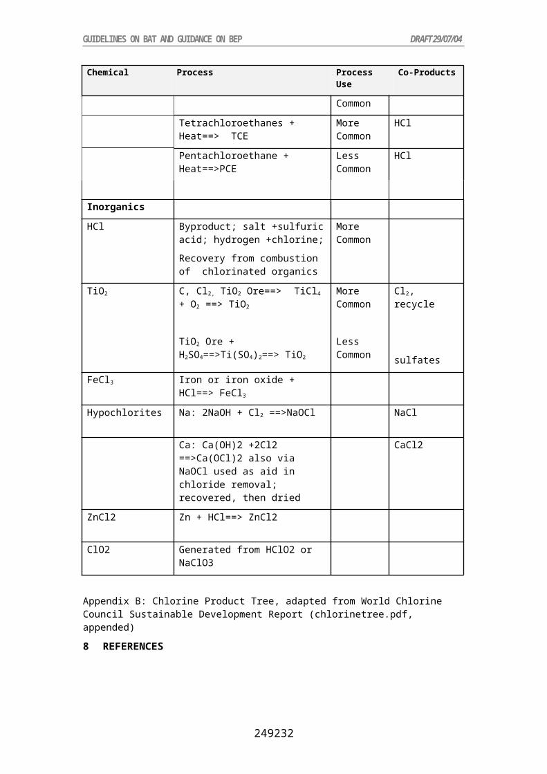
base oil is combined with a fresh additive by the blender to make the finished lubricant. In Europe, fourteen percent of used oil collected is turned over to re-refiners who return used oil to its original virgin oil state.
Principally, used oil can be re-refined over and over again, and is subject to the same stringent refining, compounding, and performance standards as virgin oil. In the United States, the American Petroleum Institute (API) has established criteria for motor oil products to guarantee the performance level, viscosity, and energy-conserving properties as well as a certification mark to tell the customer that the product one is buying has met all the current performance specifications established by the oil industry, and the vehicle and engine manufactures.
2.1.1 Type of Waste Oil Eligible for Regeneration
In general, WO (waste oils) not too heavily polluted and with a high viscosity index (HVI) are the most suitable to regeneration. The GEIR (Groupement Européen de l’Industrie de la Régénération GEIR, Belgium) and re-refiners consider the following WO suitable for regeneration:
engine oils without chlorine (European Waste Category98 EWC code: 130205), hydraulic oils without chlorine (EWC code: 130110), non-chlorinated mineral diathermic oils (EWC code: 130306).
Under certain conditions (limitation of chlorine or PCB content), this list could be extended to the following categories:
engine oils with chlorine (EWC code: 130204), hydraulic oils with PCB (EWC code: 130101), hydraulic oils with chlorine (EWC code: 130109).
Several experts insist on the fact that the waste oil composition is becoming more and more complex, due to different factors:
The increasing use of dispersants as well as esters and poly-alpha-olefins, e.g., to increase the life of the oil. As a result, the waste oil become more complex and dirty over time.
The progressive displacement of conventional mineral based auto lubricants by “synthetic” products which have enhanced performance characteristics. Whereas some of these synthetic products can be regenerated along with mineral oils, others (based upon esters for instance) are less suitable to regeneration because they tend to be less stable in the presence of caustic (often used by regeneration processes) and less stable to the hydro-finishing step.
2.1.2 Quality of the Base Stock Produced Outlets
Re-refined base oils are speciality products used in automotive lubricants and industrial lubricants (hydraulic oils). The quality of the base oils produced by regeneration is still a matter for discussion between industrial actors, even though that quality has largely improved with processes such as hydro-treatment and solvent extraction.
Modern regeneration technologies (i.e. not for instance the acid/clay process) allow to produce premium quality base oils: at least Group I according to the API base oils classification and, when resorting to a severe hydro or solvent finishing, Group II base oils.
There is a perfect comparability between severely hydro-treated re-refined base oils and virgin base oils (viscosity index, volatility, chlorine content, etc.).
As for the base oils quality:
98 European codes used by the EC to classify waste oil according to Commission Decision 2000/532/EC as amended

it is not very dependent on the variation of the origin and type of waste oil collected (the variations of base oils quality are actually not different from the variations of virgin base oils quality); it is thus possible to obtain reasonably consistent base oil products from a specific regeneration plant,
it is very dependent on the different processes and production plants.
2.1.3 Regeneration Options (waste oil back to Base Oil)
2.1.3.1 Acid/Clay Process
The polycyclic aromatic hydrocarbon (PAH) content of the base oils produced can be comparatively high (4 to 17 times higher than virgin oils, according to the authors), and the health implications need to be assessed.
2.1.4 Other Processes
2.1.4.1 Vacuum Distillation + Chemical Treatment or Clay Treatment
The base oils produced by clay treating or by chemical treatment have a metal content of <1 ppm. This process may not reduce the PAH content of the oil by as much as hydrotreatment. Used clay and used chemicals must be safely disposed of; the best route is to burn them in cement kilns or in a chemical waste incinerator.
2.1.4.2 Vacuum Distillation + HydroTtreatment
This process reduces the PAH content of oil much more (no figure) than the clay treatment or chemical treatment. The disposal of spent hydro-treating catalyst should be handled by a specialised company familiar to this problem.
2.1.5 New Regeneration Options under Development
2.1.5.1 UOP-DCH-Process
By treating the whole used oil with hydrogen, the DCH process generates effluents with low environmental loads. By-products requiring disposal will include spent catalyst, sodium chloride and sodium sulphate.
2.1.5.2 Refinery Recycling
This disposal option has been studied on a small scale in France. All the metal contaminants will be encapsulated in asphalt and leaching of metals will be extremely low (no figure in the report). However, problems of corrosion damage to the plant need to be solved before this can be considered viable option.
PCB content is not considered to be a significant problem for waste oil disposal in Europe (as under the waste oil directive, the maximum content of PCB allowed in waste oil to be treated for disposal is 50 ppm).
Waste oil can have a significant, but variable, chlorine content, including organochlorines. This has implications for all the disposal options considered, whether regeneration or combustion. The fate of these chlorine compounds will vary, not only with the disposal route, but also with the form in which the chlorine is present. It is therefore difficult to make any general comment on the effects of chlorine other than that in the combustion routes there is a risk of dioxin formation and that in the reprocessing options there are risks of corrosion problems, acid gas emissions and contamination of products and by-products. These can only be assessed and compared with emissions from other sources on a case-by-case basis.
2.2 Thermal Cracking
Various technologies exist for cracking waste oils for use as automotive or gaseous fuels. A typical process starts with filtering the oil to remove any particulates that might damage the equipment, after which any water is flashed off. The remaining oil is cracked in a vessel such as a kettle or a kiln (depending on the duty required), before fractionation into various cuts.

The main drawback is that it is an energy intensive process requiring sophisticated, and thus costly, equipment. The process can not compete directly with the direct use of waste oil as a fuel.
Thermal cracking can accept various types of hydrocarbon feedstock: waste oil , waste marine fuels, deep frying oils and, possibly with design considerations, waste plastics. The strategy of thermal cracking is to produce high quality products ranging from de-metallized heavy fuel oil to re-refined light industrial lube oil, including gasoil products. Thermal cracking is a common refinery process that is well known and proven; the first plant in Europe was scheduled to be operational by the end of 2001 in Belgium99.
2.2.1 Type of Waste Oil Eligible for Thermal Cracking
Thermal cracking can accept various types of hydrocarbon feedstock: waste oil, waste marine fuels, deep frying oils and, possibly with design considerations, waste plastics.
2.2.2 Type of Outputs Produced and Markets
The strategy of thermal cracking is to produce high quality products ranging from demetallised heavy fuel oil to re-refined light industrial lube oil, including gasoil products. As described below, thermal cracking offers a big adaptability to the changing market values of products.
According to the promoters of thermal cracking, the gasoil products for instance presents the following advantages:
a relative high value compared to other fuels (heavy distillate fuel oils, residual replacement fuels) derived from waste oil by other re-processing technologies,
a cleaner burning, as a commodity product, large markets and marketable anywhere in the world.
2.2.3 Available Processes
Thermal cracking is a common refinery process that is well known and proven. No plant already exists in Europe for waste oil : the first plant will be operational by the end of 2001 in Belgium.
Thermal cracking, visbreaking, catalytic cracking, fluid catalytic cracking, hydrocracking and coking are all variations on the basis of the basis principle of breaking or cracking the large hydrocarbon molecules (CxHy with 30 carbons) into smaller ones (CxHy with 10 to 18 carbons) by the application of sufficient heat in a pressurised vessel. In this fashion, larger molecules of more viscous and less valuable hydrocarbons are converted to less viscous and more valuable liquid fuels. The yield can reach 70 %.
A 20 kt facility (Guascor group) operates in Spain a simple thermal cracking process and mixes all the light and heavy fractions obtained to feed a thermal engine producing electricity. But this process is very specific and differs from those described in this chapter.
Several processes exist today, such as:
the Springs Oil Conversion, the Great Northern Processing Inc. (GNP) used oil thermal cracking process.
The Springs Oil Conversion is developed by Silver Springs Oil Recovery Inc, Canada. Two processes are available:
SOC1: the de-watering is followed by the thermal cracking performed in fired heater coils with soaking drums or heated kettles.
This process is suitable to small plants, in the 6 kt to 15 kt/a range. But it is limited in the feed.
99 No information available

SOC2: the de-watering is followed by the thermal cracking performed in an indirectly fired rotary kiln.
It is suitable to large capacities and can process also oils more refractory to thermal cracking (such as synthetic oils) and higher carbon residues (bunker fuels, etc.).
The GNP technology is developed in the United States, offered under license by Propak Systems Ltd., Canada, and marketed by Par Excellence Developments, Canada.
This thermal cracking of waste oil , utilizing ‘refinery calibre’ systems and equipment, is a relatively recent development: in 1995-96, this process was successfully re-applied in a 30 kt commercial operating plant by a US company to produce high quality gasoil distillate from a feedstock of waste oil.
It is this technology which will be installed in Belgium by the end of 2001. The 40 kt/a plant will be operated by WATCO. The process consists in a screening and de-watering section, followed by a thermal cracking section, then a separation or distillation depending on the product slate desired and finally a purification and stabilisation stage.
This technology is characterised by a large operational and product flexibility and adaptability to the changing market values of products. It can also be manipulated to maintain product quality with feed variability.
As a matter of fact, the process operational conditions (temperature, pressure, residence time, etc.) can be varied to produce a primary product (be it heavy fuel oil, gasoil or base oil) to be maximized and secondary product streams (consumed in the process for calorific value or sold) to be minimized.
2.3 Burning Options
Waste oil used as a direct source of energy must undergo basic treatment to remove water and particulates before it is fit for use as fuel. In the UK, the majority of the waste oil is currently used as fuel by industries such as power generation, road-stone coating and cement manufacturing. Higher levels of pre-treatment can remove water, sediments, heavy hydrocarbons, metals and additives. The oil products from these processes have similar properties and emissions levels to virgin oils, but cost and volume constraints mean that these do not tend to compete directly.
2.3.1 Cement Kiln Disposal
High operating temperatures are required in a cement kiln to convert the raw materials into cement and the raw materials used are highly alkaline. PCDD/PCDF measurements from co-incineration of waste oils are available and presented in detail in the Guidance Document on “Cement Kilns Firing Hazardous Waste” (Draft 2004).
2.3.2 Burning in Space Heaters
Used oil is burned in space heaters specially designed for burning waste oil and are typically used in some countries to heat automotive repair garages. Volatile metals and chlorine compounds are emitted with the stack gas from the burner. The metal of most concern is lead (from leaded gasoline). Although the lead problem must soon disappear, as leaded fuel is banned from 2000, combustion in such equipment cannot be tightly monitored.
2.3.3 Burning after "Mild" Reprocessing in Road Limestone Coating Plants
According to a report on the range of emissions observed at 26 sites in UK, the emissions of metals from stone coating plants was, in 1996, above those of cement kilns, but below the European emission limit values. In these plants, the pollutants, particularly metals, are captured by the stones, which are then encapsulated by bitumen for roads thus preventing leaching. The combustion temperature is not high enough to destroy PCBs and the report did not include information on emissions of chlorinated compounds such as PCDD/PCDF, PCB, and HCB.

3 Existing Technologies for Waste Oil Regeneration
3.1 European Situation
The different waste oil (WO) disposal routes as they exist in the European Union are shown in Figure 9.

Figure 9: The different waste oil disposal routes (from EC 20
4 Waste Oil Recycling: Markets, Capacities, and Constraints
Five aspects of the regeneration need to be addressed:
the type of waste oil which are regenerable (input),
the quality of the base stock produced (out put) and the outlets,
the existing technologies,
the success criteria for a regeneration plant,
the economics of regeneration.
Oil filter recycling also needs to be included into the management options for waste oils: most garages and workshops send oil filters for recovery at specialist plants. The standard process is to compress the filters, squeezing out the oil, which can then be treated using one of the above processes. The solid remainder, compressed into a block, is passed to metal reprocessing plants, although the contaminated nature of the filters means that the consignment has to be treated as special waste.
5 Existing Regeneration Technologies
Even if most of the existing capacities are still operating the old acid / clay process, numerous major processes exist in Europe and world-wide.
They may differ by the technology used for one or several of the following operations:
o de-watering and de-fuelling (removal of water, light ends and fuel traces (naphtha10…)),
o de-asphalting (removal of asphaltic residues: heavy metals, polymers, additives, other degradation compounds),
o fractionation (in two or three cuts), o finishing.
The following table describes most of them.
As for the finishing, the hydro-treatment is today the most efficient one. It aims at reducing or removing remaining metals and metalloids, organic acids, compounds containing chlorine, sulphur and nitrogen. Operating under a high pressure and at high temperatures, it also reduces the PAH (polycyclic aromatic hydrocarbon) content to an acceptable level (health implications said to be comparable to those of virgin base oil). Considering the quality demand by users and the increasing complexity of engine oils composition, a severe hydro-treatment may be less and less an optional extra in the future.

Figure 10: Description of main regeneration technologies

Figure 10 (cont’d): Description of main regeneration technologies

Figure 10 (cont’d): Description of main regeneration technologies

6 Occurrence of PCDD/PCDF in Used Oils and Emissions
Hagenmaier and Brunner (1986) analyzed new motor oils, used motor oils (after 10,000 km in cars fueled with leaded gasoline), and recycled oil products for PCDD/PCDF. At a limit of quantification of 0.05 g/kg per congener, no PCDD/PCDF could be quantified in the fresh and used motor oils. However, higher chlorinated PCDD/PCDF were identified in recycled oils (sum of PCDD(Cl6-Cl8) = 24.8-69.1 ng/g and sum of PCDF(Cl7-Cl8) = 1.9-4.8 ng/g). Pentachlorophenol and its sodium salt, which in Europe were used in the mineral oil industry100, were identified as the source of the contamination.
The first limit value for PCDD/PCDF in Germany was established in September 1985 when a survey on various emitters in the State of Northrhine-Westphalia gave high concentrations in the stack gases from waste oil refineries. The regulation stipulated that only used oils with a PCB content of <1,000 mg PCB could be incinerated; the emission limit value was set at 0.1 ng/Nm³ for 2,3,7,8-Cl4DD (TCDD) and 1 ng/Nm³ for 2,3,7,8-Cl4DF (TCDF) (Bröker and Gliwa 1986). Concentrations of PCB in waste oils and PCDD/PCDF emissions from three plants that burned used oils (plants 1 and 2) and waste oil sludges (plant 3) are shown in Table 24 and Error: Reference source not found. As can be seen the emissions from plant 3 clearly exceeded the limit of 0.1 ng 2,4,7,8-Cl4DD and all emissions were above the 1 ng/Nm³ limit for 2,3,7,8-Cl4DF.
Table 26: Concentrations of PCB in used oils (Bröker and Gliwa 1986)
Type of oil PCB (6 congeners)mg/kg
Total PCB (6 congeners x5)mg/kg
Used oil from plant 6.1 30.5Used oil from motor vehicles 0.8 4.0Scrap oil 13.3 66.5Pooled sample from 5 garages 0.6 3.0
Table 27: Concentrations of PCB in used oils being burned and PCDD/PCDF emissions in the stack gases from three waste oil recycling plants incinerating these oils (Bröker and Gliwa 1986)
Plant PCB input(ppm)
2,3,7,8-Cl4DD(ng/Nm³)
PCDD(ng/Nm³)
2,3,7,8-Cl4DF(ng/Nm³)
PCDF(ng/Nm³)
Plant 1 62 0.53 33.9 1.53 67.1Plant 2 1.5 0.067 60.2 3.02 146Plant 3 9.8 0.81 618 37.1 1,651
In a plant that recycled used oils, PCDD/PCDF analyses gave the results as shown in Table 28. The building had a rotary kiln and used heavy used oils and related wastes such as oils, acis resins, used tyres, etc. as fuels. It should be noted that the high PCDD/PCDF concentrations mainly were caused by the operation of the process (Fiedler et al. 1995).Table 28: PCDD/PCDF concentrations in building materials from a waste oil recycling plant;
concentrations in ng/kg (Fiedler et al. 1995)Material PCDD PCDF BGA-TEQConcrete floor (surface, down to 10 mm) 8,100 2,200 143Concrete floor (interior 10-100 mm) 630 300 14Wall brick (depth 1-10 mm) 90 50 17Wall brick (inside 10-100 mm) 51 34 7Chimney brick (40 m high, outer surface) 12 ND. (0.1)
100 According to the Association of the Chemical Industry, Germany, 5 to 60 tons of PCP and PCP-Na was sold annually to the mineral oil industry during the years 1979 and 1984.

7 Selected Country Situation
The most common causes of oil pollution are inadequate storage and deliberate disposal down drains. This applies both to waste oil and to virgin oil. The Regulations are likely to affect all industrial, commercial and institutional users who accumulate oil in containers larger than 200 liters (DTI 2001).
7.1 European Union
7.1.1 Legislation
Waste oil is classified as hazardous waste (in chapter 12 and 13 of the hazardous waste list). The waste terminology in Directive 75/439/EEC on waste oils (such as disposal, processing, regeneration and combustion) differs from the framework Directives and the Waste Management Strategy. Thus "disposal of waste oil" means any treatment (processing, destruction, storage and tipping) whereas "disposal of waste" means operations listed in Annex II A such as incineration without energy recovery or landfilling.
The terminology of the Directive 87/101/EEC on waste oils differs from the terminology of the earlier Directive 75/442/EEC. The present Directive includes a definition of "waste oil" and waste oil management terminology such as disposal (any treatment/handling), processing (regeneration and combustion), regeneration (refining into base oils), combustion (use as fuel) and collection (ref. Article 1). The main objectives of the 1987 Directive is One of the main axes of the directive 75/439/EC on Waste Oils (WO), amended in 1987, is that, among the different options for recovery, priority is given to the regeneration of waste oils over their incineration.
The main provisions of Directive 75/439/EEC on waste oil and its amendment 87/101/EEC are as follows:
The general objective of the waste oils management is to avoid any damage to man or the environment (Article 2);
Hierarchy of waste oils management: priority is given to the processing of waste oils by regeneration; otherwise waste oils have to be burned under environmentally acceptable conditions; safe destruction and controlled storage or tipping when both other options are not feasible (Article 3);
Prohibition of: discharge of waste oils into waters, discharge harmful to the soil and uncontrolled discharge, processing exceeding existing emission levels (Article 4);
Public information and promotional campaigns to ensure appropriate storage and collection as far as possible; undertakings may carry out collection and/or disposal; Member States may decide to allocate the waste oils to any of the types of processing (Article 5);
Permit requirement for undertakings, provisions for processing, provisions for combustion (emission values for plants with a thermal input of 3 MW and more, adequate control for plants with less thermal input) (Articles 6, 7, 8);
Specific requirements with regard to PCB/PCT (Article 10);
Requirement to keep records, convey of information to competent authorities, periodic inspections, examination of technical development and adaptation of permits (Articles 11, 12, 13).
7.1.2 European Union – Country Situation
The current situation of waste oil (WO) management in Europe can be summarized as shown below; however, it should be noticed that the data quality if poor.
About 4,930 kt of base oils were consumed in Europe in 2000, among which about 65 % of automotive oils and less than 35 % of industrial oils.

About 50 % of consumed oils are lost during use (combustion, evaporation, residues left in the container, etc.). The remaining 50 % represent the collectable waste oil.
Engine oils represent more than 70 % of 2,400 kt of the collectable waste oil (black industrial oils about 5 % and light industrial oils less than 25 %).
Engine oils (and to a lower extent black industrial oils) are potentially suitable for regeneration, whereas light industrial oils, clean, join an independent recovery circuit.
The average waste oil collection rate reached about 70 %-75 % in the EU in 2000. Approximately 1,730 kt of waste oils were collected. The remaining 675 kt (25 %-30 %) are accounted as illegally burnt or dumped in the environment. It still vary from country to country.
The efficiency of the waste oil collection systems is often very high for engine oils (more than 80 %) and low for black industrial oils (less than 10 %).
The waste oil collection rate in the year 2000 for the EU Member States is shown in Figure 11.
Figure 11:Waste oil collection rate in EU Member States for 2000 (EC 2001)
Appropriate collection and disposal arrangements for waste oil from industrial or automotive origin (garages, etc.) are generally well established in Europe. However, waste oil from “Do-it-Yourself” (DIY) oil changes are less likely to be collected and so present the greatest risk of improper disposal. At present many treatment processes exist (or are under development) in Europe. The most important are listed in Table 29.
An average of 25 % of the collectable waste oil (and 33 % of the collected WO) would have entered a regeneration plant in the EU in 1999.
About 50 % of waste oils were energetically used in the E.U., in 1999.
Cement kilns play an important role in the energetic use of waste oil: about 400 kt of waste oils are burnt in cement kilns, which represents about 17 % of the total waste oils and 35 % of the waste oil burnt. Cement kilns are the major treatment route in France, Germany, and Sweden, and the only routes in Austria, Belgium, Italy, and the United Kingdom
About 25 % of waste oils were still illegally disposed of in 1999.
Table 29: Treatment processesfor waste oil applied in EU Member StatesType of Waste Oil Type of Treatment ProductsClean waste oil Reuse Hydraulic or cutting oils by:
electricity companies, shipping industry, major engineering companies;
Mould or base oil for the production chain saw oil
Engine waste oil + clean waste oil
Regeneration or refining Lubricant base oil
All types of waste oil including sy nthetic oils
Thermal cracking Distillate gas oil products, e.g., gas oil (also called heating oil,
diesel oil, furnace oil); de-metallized fuel oil; marine gas oil;- re-refined light base oil.
Mixed wastes Gasification Synthetic gas: hydrogen, methanolAll types of waste oil, especially heavy polluted ones
Severe re-processing De-metallized fuel oil (or heavy distillate): marine diesel oil, fuel oil for heating
Mild re-processing then burning
Replacement fuel, used in road stone plants, cement kilns, large marine engines, pulverized power stations, etc.
Direct burning in waste incinerators, cement kilns, greenhouses, workshops, etc.
The following consolidated report is based on the questionnaire adopted by Commission Decision 94/741/EC of 24 October 1994. According to Directive 91/692/EEC Member States were obliged to submit their reports; however, the consolidated report only refers to eleven Member States.
The eleven Member States (two regions of Belgium, Denmark, Germany, France, Ireland, Luxembourg, the Netherlands, Austria, Finland, Sweden and the United Kingdom)101, which submitted their reports on the period 1995 to 1997 by 30 September 1998, confirmed that they have provided the Commission with details of the current laws and regulations in force to incorporate the Directive 75/439/EEC on the disposal of waste oils as amended into national law.
The provisions regarding the regeneration of waste oil include that Member States shall take the necessary measures to ensure that the operation of the regeneration plant does not cause avoidable damage to the environment (Article 7 (a)). In addition Member States ensure that base oils derived from regeneration do not constitute a hazardous waste and do not contain PCB/PCT in concentration beyond the limits of 50 part per million (ppm) (Article 7 (b)).
The report showed the following:
Status Country Domestic Waste Oil RegenerationNo report submitted Greece, Italy, Portugal, and Spain No informationNo legislation in place Belgium – Walloon Region, Ireland, the
NetherlandsNo
Austria YesFrance Yes
101 Greece, Italy, Portugal, and Spain did not send their reports

Legislation in place Denmark, Finland, and Sweden NoGermany (Federal Immission Control Act and Waste Oil Ordinance of 1987)
Yes
Luxemburg (Grand-Ducal Regulation of 30 November 1989)
No
United Kingdom (Environmental Protection Act 1990; Regulations on Environmental protection (Procedures and substances) 1991
Yes
Belgium – Flemish Region No informationThe Directive in Article 16 opens for more stringent national measures for the purpose of environmental protection. With the exception of France, Ireland, and the United Kingdom all reporting Member States indicated that they have taken more stringent measures than provided by the Directive for the purpose of environmental protection. These measures differ between stricter priority for regeneration (Luxembourg), stricter emission limit values (Germany), stricter values for the PCB content (the Netherlands). Remaining countries did not specify their measures.
7.1.3 Waste Oils Management
In the years 1994/1995 and in the European Union, the mean rates of waste oil generated was 48 % and waste oil collected was 74.6%; the percentage share of regeneration was 36 % and of combustion was 64 %. The Commission considers the refining route as “regeneration” and the route untreated oil and the use after limited treatment for energetic use as well as the reprocessing into fuel oil as “combustion”. It was found that the figures for waste oil generated differed widely between 33 and 66 % of the oil launched on the market.
7.1.4 Waste Oil Hierarchy
According to Article 3 (1) and (2) Member States shall give the first priority to the regeneration of waste oils and second priority to the combustion of waste oils under environmentally acceptable conditions where technical, economic and organizational constraints so allow. Where the constraints do not allow regeneration or combustion, Member States shall take the necessary measures to ensure the safe destruction or controlled storage of waste oils (Article 3 (3)).
7.1.5 Limit Values and Other Obligations
According to Article 8 (1) Member States shall ensure that the emission values for combustion plants with a thermal input of more than 3 MW (Annex) are being observed. Member States may at any time set more stringent limit values or set limit values for other substances and parameters. Austria, Denmark, Finland and Germany implemented stricter limit values. Austria determined limit values for additional substances
The limit values for sulphur dioxide and dust, which had to be set by Member States, vary between 50 and 1,700 mg/Nm³ for sulphur dioxide and between 10 and 100 mg/Nm³ for dust.
According to Article 11 each Member State has to specify the quantity of waste oils (which must be below 500 liters per year) which oblige any establishment (producing, collecting and/or disposing of waste oil) to keep records. These records have to be conveyed on request to the competent authorities. Germany set a minimum quantity of 100 litres of waste oil.
7.1.6 Technical and Economic Analysis of Waste Oil Regeneration
There is no major technical bottleneck for regeneration development since the technologies exist and the quality of base stocks produced is comparable to virgin base oils (Group I and even Group II when a severe hydro or solvent treatment is used for the finishing step). However, it remains to be seen whether the latest technical advances in regeneration prove to be sufficiently flexible to handle the changing composition of waste oil over the next 10 years and the possible increase of bio-lubricants consumption.

The above mentioned uncertainty generates risks for investors in regeneration facilities.
The economic bottleneck is obvious. In most of the cases, a regeneration plant is not economically self sufficient from the beginning102. At the tail end, potential users of re-refined base oils, in the automotive or industrial sector, are still reluctant to use regenerated products.
7.2 Germany
In Germany, plants for the distillation, raffination or further treatment of crude oil or crude oil products in mineral oil, waste oil or lube oil refineries need a permit according to the German Law on Immissions (BImSchG) and the 4th Ordinance on Immissions (4th BImSchV).
7.3 United States of America
API: More than 640 million gallons of motor oil were sold in 1997; 345 million gallons of that was sold to do-it-yourselfers (those that change their own oil), with the remaining going to the do-it-for-me service industry. Many service stations with repair facilities and oil change shops will accept your used oil for no charge
Reprocessing is the most common method of recycling used oil in the U.S. Each year processors treat approximately 750 million gallons of used oil. However, it seems that the U.S. have a definition of “recycling” different from other countries. The report states that seventy-five percent of used oil is being reprocessed and marketed to:
43 % asphalt plants; 14 % industrial boilers (factories); 12 % utility boilers (electric power plants for schools, homes, etc.); 12 % steel mills; 5 % cement/lime kilns; 5 % marine boilers (tankers or bunker fuel); 4 % pulp and paper mills; >1 % commercial boilers (generating heat for school, offices, etc.); 5 % other.8 References
API: American Petroleum Institute, USA. WebPage http://www.recycleoil.org/
Bröker G. (1980): Altölraffination – ein sinnvolles Recyclingverfahren? Schriftenreihe der Landesanstalt für Immissionsschutz des Landes NRW, Heft 50, 7-16
Bröker G. And H. Gliwa (1986): Dioxin- und Furanemissionen bei der Verbrennung von Altöl. Staub – Reinh. Luft 46, 435-438
DTI (2001): Waste Oil Recycling. Information sheet by Department of Trade and Industry, London, UK
EC (2001): Critical Review of Existing Studies and Life Cycle Analysis on the Regeneration and Incineration of WO. Study 20 AW 83–5 prepared by Taylor Nelson Sofres Consulting for European Commission, DG Environment A2 – Sustainable Resources Consumption and Waste, Brussels, Belgium, December 2001
EU (1975): Directive 75/439/EEC on waste oils. Commission of the European Community OJ L 194, 25.07.1975, pp 31
EU (1987): Directive 87/101/EEC = amendment to Directive 75/439/EEC. OJ L 42, 22.12.1986, pp 43
Fiedler H., C. Lau, G. Rippen, H.F. Wesp, O. Hutzinger, F. Vahrenholt, S. Sievers, P. Friesel, B. Gras, T. Reich, U. Schacht, and R. Schwörer (1996): Dioxin-Bilanz für Hamburg. in:
102 It would need to receive between 10 and 100 Euros for each ton delivered to the plant, depending on the technology, the capacity and the market conditions.

Rippen – Handbuch Umweltchemikalien, 37.-41. Erg. Lfg. 12/96 ff (320 pages). ecomed Verlagsgesellschaft, Landsberg, Germany
Hagenmaier H. and H. Brunner (1986): Bestimmung polychlorierter Dibenzodioxine und polychlorierter Dibenzofurane in Motorölen, Altölen und Zweitraffinaten. Fresenius Z. Anal. Chem. 324, 23-26