Embed Size (px)
Citation preview
12‐07M
01 00 00 ‐1
SECTION 01 00 00 GENERAL REQUIREMENTS
TABLE OF CONTENTS
1.1 GENERAL INTENTION…………………….………………………..……………………1
1.2 STATEMENT OF BID ITEM(S)……………………………………………….…………….1
1.3 SPECIFICATIONS AND DRAWINGS FOR CONTRACTOR……………………………...1
1.4 CONSTRUCTION SECURITY REQUIREMENTS………………………………………....1
1.5 FIRE SAFETY…………………...……………………………………………………………3
1.6 OPERATIONS AND STORAGE AREAS……………………………………………………4
1.7 ALTERATIONS…………………………………………………………………………..…..8
1.8 INFECTION PREVENTION MEASURES…………………………………………………..9
1.9 DISPOSAL AND RETENTION…………………………………………………...…………9
1.10 PROTECTION OF EXISTING VEGETATION, STRUCTURES, EQUIPMENT, UTILITIES, AND IMPROVEMENT ………………………...…………………………………9
1.11 RESTORATION……………………………………………………………………………..9
1.12 PHYSICAL DATA ……………………………………………………………………...…10
1.13 LAYOUT OF WORK…………………………………………………………………..…..10
1.14 AS‐BUILT DRAWINGS…………………………………………………………….……..12
1.15 USE OF ROADWAYS……………………………………………………………….…….12
1.16 TEMPORARY TOILETS………………………………………………...………………..12
1.17 AVAILABILITY AND USE OF UTILITY SERVICES……………………..…………...12
1.18 TESTS………………………………………………………………………..……………13
1.19 INSTRUCTIONS…………………………………………………………..……..…….....14
SECTION 01 00 00 GENERAL REQUIREMENTS
12‐07M
01 00 00 ‐2
1.1 GENERAL INTENTION
A. Contractor shall completely prepare site for operations, including demolition and removal of
existing structures, and furnish labor and materials and perform work for Project 520‐14‐126
Install Nuclear Med Hood – Replace Domestic Water Controls JACC as required by drawings and
specifications.
B. Visits to the site by bidders may be made only at the date and time specified in FAR 52.236‐27,
SITE VISIT (CONSTRUCTION), ALTERNATE I.
C. All employees of general contractor and subcontractors shall comply with VA security
management program and obtain permission of the VA police, be identified by project and
employer, and restricted from unauthorized access.
D. Prior to commencing work, general contractor shall provide proof that a OSHA certified
“competent person” (CP) (29 CFR 1926.20(b)(2) will maintain a presence at the work site
whenever the general or subcontractors are present.
E. Training:
1. Beginning July 31, 2005, all employees of general contractor or subcontractors shall have the
10‐hour OSHA certified Construction Safety course and /or other relevant competency
training, as determined by VA CP with input from the ICRA team.
2. Submit training records of all such employees for approval before the start of work.
1.2 STATEMENT OF BID ITEM(S)
A.ITEM I, GENERAL CONSTRUCTION: Refer to Scope of Work.
1.3 SPECIFICATIONS AND DRAWINGS FOR CONTRACTOR
A. AFTER AWARD OF CONTRACT, __1___ sets of specifications and drawings will be furnished.
B. Additional sets of drawings may be made by the Contractor, at Contractor's expense, from
reproducible sepia prints furnished by Issuing Office. Such sepia prints shall be returned to the
Issuing Office immediately after printing is completed.
1.4 CONSTRUCTION SECURITY REQUIREMENTS
A. Security Procedures:
12‐07M
01 00 00 ‐3
1. General Contractor’s employees shall not enter the project site without appropriate badge.
They may also be subject to inspection of their personal effects when entering or leaving the
project site.
2. For working outside the “regular hours” as defined in the contract, The General Contractor
shall give 3 days notice to the Contracting Officer so that security/escort arrangements and
extended base access can be provided. This notice is separate from any notices required for
utility shutdown described later in this section.
3. No photography of VA premises is allowed without written permission of the Contracting
Officer.
4. VA reserves the right to close down or shut down the project site and order General
Contractor’s employees off the premises in the event of a national emergency. The General
Contractor may return to the site only with the written approval of the Contracting Officer.
B. Document Control:
1. The General Contractor is responsible for safekeeping of all drawings, project manual and
other project information. This information shall be shared only with those with a specific
need to accomplish the project.
2. Certain documents, sketches, videos or photographs and drawings may be marked “Law
Enforcement Sensitive” or “Sensitive Unclassified”. Secure such information in separate
containers and limit the access to only those who will need it for the project. Return the
information to the Contracting Officer upon request.
3. These security documents shall not be removed or transmitted from the project site without
the written approval of Contracting Officer.
4. All paper waste or electronic media such as CD’s and diskettes shall be shredded and
destroyed in a manner acceptable to the VA.
5. Notify Contracting Officer and Site Security Officer immediately when there is a loss or
compromise of “sensitive information”.

12‐07M
01 00 00 ‐4
6. All electronic information shall be stored in specified location following VA standards and
procedures using an Engineering Document Management Software (EDMS).
a. Security, access and maintenance of all project drawings, both scanned and electronic
shall be performed and tracked through the EDMS system.
b. “Sensitive information” including drawings and other documents may be attached to e‐
mail provided all VA encryption procedures are followed.
C. Motor Vehicle Restrictions: IAW VA requirements; as a minimum, proper state drivers license,
proof of insurance, and proof of vehicle registration required to operate motor vehicle on VA
premises.
1.5 FIRE SAFETY
A. Applicable Publications: Publications listed below form part of this Article to extent referenced.
Publications are referenced in text by basic designations only.
1. American Society for Testing and Materials (ASTM):
E84‐2007 .............................. Surface Burning Characteristics of Building Materials
2. National Fire Protection Association (NFPA):
10‐2006................................ Standard for Portable Fire Extinguishers
30‐2003................................ Flammable and Combustible Liquids Code
51B‐2003 ............................. Standard for Fire Prevention During Welding, Cutting and Other
Hot Work
70‐2005................................ National Electrical Code
241‐2004 ............................. Standard for Safeguarding Construction, Alteration, and
Demolition Operations
3. Occupational Safety and Health Administration (OSHA):
29 CFR 1926 ......................... Safety and Health Regulations for Construction

12‐07M
01 00 00 ‐5
B. Site and Building Access: Maintain free and unobstructed access to facility emergency services
and for fire, police and other emergency response forces in accordance with NFPA 241.
C. Egress Routes: Maintain free and unobstructed egress. Inspect daily.
D. Fire Extinguishers: Provide and maintain extinguishers in construction areas and temporary
storage areas in accordance with 29 CFR 1926, NFPA 241 and NFPA 10.
E. Flammable and Combustible Liquids: Store, dispense and use liquids in accordance with 29 CFR
1926, NFPA 241 and NFPA 30.
F. Existing Fire Protection: Do not impair any fire protection systems in the accomplishment of
work. Provide fire watch for impairments more than 4 hours in a 24‐hour period. Request
interruptions in accordance with Article, OPERATIONS AND STORAGE AREAS, and coordinate
with COTR and base facility Safety Officer.
G. Hot Work: Perform and safeguard hot work operations in accordance with NFPA 241 and NFPA
51B. Coordinate with COTR. Obtain permits from facility Safety Officer at least __72__ hours in
advance.
H. Fire Hazard Prevention and Safety Inspections: Inspect entire construction areas weekly.
Coordinate with, and report findings and corrective actions on construction progress reports
(aka “daily logs”), which are part of the construction contract record documents.
I. Smoking: Smoking is prohibited in and adjacent to construction areas inside existing buildings
and additions under construction. Comply with all base smoking restrictions.
J. Dispose of waste and debris in accordance with NFPA 241. Remove from buildings/site daily.
K. Perform other construction, alteration and demolition operations in accordance with 29 CFR
1926.
1.6 OPERATIONS AND STORAGE AREAS
A. The Contractor shall confine all operations (including storage of materials) on Government
premises to areas authorized or approved by the Contracting Officer. The Contractor shall hold
and save the Government, its officers and agents, free and harmless from liability of any nature
occasioned by the Contractor's performance.

12‐07M
01 00 00 ‐6
B. Temporary buildings (e.g., storage sheds, shops, offices) and utilities may be erected by the
Contractor only with the approval of the Contracting Officer and shall be built with labor and
materials furnished by the Contractor without expense to the Government. The temporary
buildings and utilities shall remain the property of the Contractor and shall be removed by the
Contractor at its expense upon completion of the work. With the written consent of the
Contracting Officer, the buildings and utilities may be abandoned and need not be removed.
C. The Contractor shall, under regulations prescribed by the Contracting Officer, use only
established roadways as authorized by the Contracting Officer. When materials are transported
in prosecuting the work, vehicles shall not be loaded beyond the loading capacity recommended
by the manufacturer of the vehicle or prescribed by any Federal, State, or local law or regulation.
When it is necessary to cross curbs or sidewalks, the Contractor shall protect them from
damage. The Contractor shall repair or pay for the repair of any damaged curbs, sidewalks, or
roads.
D. Working space and space available for storing materials shall be as determined by the COTR and
base.
E. Workmen are subject to rules of VA applicable to their conduct.
F. Execute work so as to interfere as little as possible with normal functioning of Base as a whole,
including operations of utility services, fire protection systems and any existing equipment, and
with work being done by others. Use of equipment and tools that transmit vibrations and noises
through the building structure, are not permitted in buildings that are occupied, during
construction, jointly by government personnel, and Contractor's personnel, except as permitted
by COTR where required by limited working space.
1. Do not store materials and equipment in other than assigned areas.
2. Schedule delivery of materials and equipment to immediate construction working areas
outside or within buildings in use by Government in quantities sufficient for not more than
two work days. Provide unobstructed access to base areas required to remain in operation.
G. Utilities Services Impact: Where necessary to cut existing pipes, electrical wires, conduits, cables,
etc., of utility services, or of fire protection systems or communications systems (except
telephone), they shall be cut and capped at suitable places where shown; or, in absence of such
12‐07M
01 00 00 ‐7
indication, where directed by COTR. All such actions shall be coordinated with the Utility
Company involved:
1. Whenever it is required that a connection fee be paid to a public utility provider for new
permanent service to the construction project, for such items as water, sewer, electricity,
gas or steam, payment of such fee shall be the responsibility of the Government and not the
Contractor.
H. Phasing: To insure such executions, Contractor shall furnish the COTR with a schedule of
approximate phasing dates on which the Contractor intends to accomplish work in each specific
area of site, building or portion thereof. In addition, Contractor shall notify the COTR two weeks
in advance of the proposed date of starting work in each specific area of site, building or portion
thereof. Arrange such phasing dates to insure accomplishment of this work in successive phases
mutually agreeable to COTR, CO, and Contractor.
I. Contractor will be allowed space on VA grounds to park temporary storage trailers. Coordinate
with VA Resident Engineer. Construction Fence if required to secure materials: Before
construction operations begin, Contractor shall provide a chain link construction fence, 2100
mm (seven feet) minimum height, around the construction storage area. Provide gates as
required for access with necessary hardware, including hasps and padlocks. Fasten fence fabric
to terminal posts with tension bands and to line posts and top and bottom rails with tie wires
spaced at maximum 15 inches. Bottom of fences shall extend to one inch above grade. Remove
the fence when directed by COTR.
J. Utilities Services: Maintain existing utility services for base at all times. Provide temporary
facilities, labor, materials, equipment, connections, and utilities to assure uninterrupted
services. Where necessary to cut existing water, steam, gases, sewer or air pipes, or conduits,
wires, cables, etc. of utility services or of fire protection systems and communications systems
(including telephone), they shall be cut and capped at suitable places where shown; or, in
absence of such indication, where directed by COTR.
1. No utility service such as water, gas, steam, sewers or electricity, or fire protection systems
and communications systems may be interrupted without prior approval of COTR. Electrical
work shall be accomplished with all affected circuits or equipment de‐energized. When an
electrical outage cannot be accomplished, work on any energized circuits or equipment shall
12‐07M
01 00 00 ‐8
not commence without the Medical Center Director’s prior knowledge and written approval.
Refer to specification Sections 26 05 11, REQUIREMENTS FOR ELECTRICAL INSTALLATIONS,
27 05 11 REQUIREMENTS FOR COMMUNICATIONS INSTALLATIONS and 28 05 11,
REQUIREMENTS FOR ELECTRONIC SAFETY AND SECURITY INSTALLATIONS for additional
requirements.
2. Contractor shall submit a request to interrupt any such services to COTR, in writing, 48 hours
in advance of proposed interruption. Request shall state reason, date, exact time of, and
approximate duration of such interruption.
3. Contractor will be advised (in writing) of approval of request, or of which other date and/or
time such interruption will cause least inconvenience to operations of base. Interruption
time approved by COTR may occur at other than Contractor's normal working hours.
4. Major interruptions of any system must be requested, in writing, at least 15 calendar days
prior to the desired time and shall be performed as directed by the COTR.
5. In case of a contract construction emergency, service will be interrupted on approval of
COTR. Such approval will be confirmed in writing as soon as practical.
6. Whenever it is required that a connection fee be paid to a public utility provider for new
permanent service to the construction project, for such items as water, sewer, electricity,
gas or steam, payment of such fee shall be the responsibility of the Government and not the
Contractor.
K. Abandoned Lines: All service lines such as wires, cables, conduits, ducts, pipes and the like, and
their hangers or supports, which are to be abandoned but are not required to be entirely
removed, shall be sealed, capped or plugged. The lines shall not be capped in finished areas, but
shall be removed and sealed, capped or plugged in ceilings, within furred spaces, in unfinished
areas, or within walls or partitions; so that they are completely behind the finished surfaces.
L. To minimize interference of construction activities with flow of base traffic, comply with the
following:
1. Keep roads, walks and entrances to grounds, to parking and to occupied areas of buildings
clear of construction materials, debris and standing construction equipment and vehicles.
12‐07M
01 00 00 ‐9
Wherever excavation for new utility lines cross or bore beneath existing roads, at least one
lane must be open to traffic at all times.
2. Method and scheduling of required cutting, altering and removal of existing roads, walks
and entrances must be approved by the COTR.
M. Coordinate the work for this contract with other construction operations as directed by COTR.
This includes the scheduling of traffic and the use of roadways, as specified in Article, USE OF
ROADWAYS.
1.7 ALTERATIONS
A. Survey: Before any work is started, the Contractor shall make a thorough survey with the COTR,
of areas and within/outside of buildings in which alterations occur and areas which are
anticipated routes of access, and furnish a report, signed by all three, to the Contracting Officer.
This report shall list:
1. Existing conditions found of areas not required to be altered.
2. Shall note any discrepancies between drawings and existing conditions at site.
3. Shall designate areas for working space, materials storage and routes of access to areas
within buildings where alterations occur and which have been agreed upon by Contractor
and COTR.
B. Re‐Survey: Fourteen days before expected partial or final inspection date, the Contractor and
Resident Engineer together shall make a thorough re‐survey of the areas of buildings involved.
They shall furnish a report on conditions then existing, of resilient flooring, doors, windows,
walls and other surfaces as compared with conditions of same as noted in first condition survey
report:
1. Re‐survey report shall also list any damage caused by Contractor to such flooring and other
surfaces, despite protection measures; and, will form basis for determining extent of repair
work required of Contractor to restore damage caused by Contractor's workmen in
executing work of this contract.
C. Protection: Provide the following protective measures:

12‐07M
01 00 00 ‐10
1. Wherever existing roof surfaces are disturbed they shall be protected against water
infiltration. In case of leaks, they shall be repaired immediately upon discovery.
2. Temporary protection against damage for portions of existing structures and grounds where
work is to be done, materials handled and equipment moved and/or relocated.
3. Protection of interior of existing structures at all times, from damage, dust and weather
inclemency. Wherever work is performed, floor surfaces shall be adequately protected prior
to starting work, and this protection shall be maintained intact until all work in the area is
completed.
1.8 INFECTION PREVENTION MEASURES
A. Establish and maintain a dust control program as part of the contractor’s infection preventive measures. Contractor shall maintain negative air pressure at all times in renovation areas. Any plastic sheeting and tape used shall be fire resistant. Plastic sheeting ducting will NOT be allowed. Contractor shall provide and install fire –resistant typical flexible metal ducting as the negative air‐pressure means. See Scope of Work for other requirements.
1.9 DISPOSAL AND RETENTION
A. Materials and equipment accruing from work removed and from demolition or parts thereof,
shall be disposed of as follows:
1. Items not reserved shall become property of the Contractor and be removed by Contractor
from base property.
1.10 PROTECTION OF EXISTING VEGETATION, STRUCTURES, EQUIPMENT, UTILITIES, AND IMPROVEMENTS
A. The Contractor shall preserve and protect all structures, equipment, and vegetation (such as
trees, shrubs, and grass) on or adjacent to the work site, which are not to be removed and which
do not unreasonably interfere with the work required under this contract. The Contractor shall
only remove trees when specifically authorized to do so, and shall avoid damaging vegetation
that will remain in place. If any limbs or branches of trees are broken during contract
performance, or by the careless operation of equipment, or by workmen, the Contractor shall
trim those limbs or branches with a clean cut and paint the cut with a tree‐pruning compound as
directed by the Contracting Officer.

12‐07M
01 00 00 ‐11
B. The Contractor shall protect from damage all existing improvements and utilities at or near the
work site and on adjacent property of a third party, the locations of which are made known to or
should be known by the Contractor. The Contractor shall repair any damage to those facilities,
including those that are the property of a third party, resulting from failure to comply with the
requirements of this contract or failure to exercise reasonable care in performing the work. If
the Contractor fails or refuses to repair the damage promptly, the Contracting Officer may have
the necessary work performed and charge the cost to the Contractor.
1.11 RESTORATION
A. Remove, cut, alter, replace, patch and repair existing work as necessary to install new work.
Except as otherwise shown or specified, do not cut, alter or remove any structural work, and do
not disturb any ducts, plumbing, steam, gas, or electric work without approval of the COTR.
Existing work to be altered or extended and that is found to be defective in any way, shall be
reported to the COTR before it is disturbed. Materials and workmanship used in restoring work,
shall conform in type and quality to that of original existing construction, except as otherwise
shown or specified.
B. Upon completion of contract, deliver work complete and undamaged. Existing work (walls,
ceilings, partitions, floors, mechanical and electrical work, lawns, paving, roads, walks, etc.)
disturbed or removed as a result of performing required new work, shall be patched, repaired,
reinstalled, or replaced with new work, and refinished and left in as good condition as existed
before commencing work.
C. At Contractor's own expense, Contractor shall immediately restore to service and repair any
damage caused by Contractor's workmen to existing piping and conduits, wires, cables, etc., of
utility services or of fire protection systems and communications systems (including telephone)
which are indicated on drawings and which are not scheduled for discontinuance or
abandonment.
D. Expense of repairs to such utilities and systems not shown on drawings or locations of which are
unknown will be covered by adjustment to contract time and price in accordance with clause
entitled "CHANGES" (FAR 52.243‐4 and VAAR 852.236‐88) and "DIFFERING SITE CONDITIONS"
(FAR 52.236‐2) of Section 00 72 00, GENERAL CONDITIONS.

12‐07M
01 00 00 ‐12
1.12 PHYSICAL DATA ‐ RESERVED
1.13 LAYOUT OF WORK, AS REQUIRED FOR WALL ERECTION
A. The Contractor shall lay out the work and shall be responsible for all measurements in
connection with the layout. The Contractor shall furnish, at Contractor's own expense, all
stakes, templates, platforms, equipment, tools, materials, and labor required to lay out any part
of the work. The Contractor shall be responsible for executing the work to the lines and grades
that may be established or indicated. The Contractor shall also be responsible for maintaining
and preserving all stakes and other marks established by the Government until authorized to
remove them. If such marks are destroyed by the Contractor or through Contractor's negligence
before their removal is authorized, the Contracting Officer may replace them and deduct the
expense of the replacement from any amounts due or to become due to the Contractor.
(FAR 52.236‐17)
1.14 AS‐BUILT DRAWINGS
A. The contractor shall maintain two full size sets of as‐built drawings which will be kept current
during construction of the project, to include all contract changes, modifications and
clarifications.
B. All variations shall be shown in the same general detail as used in the contract drawings. To
insure compliance, as‐built drawings shall be made available for the COTR’s review, as often as
requested.
C. Contractor shall deliver two approved completed sets of as‐built drawings to the COTR within 15
calendar days after each completed phase and after the acceptance of the project by the COTR.
D. Paragraphs A, B, & C shall also apply to all shop drawings.
1.15 USE OF ROADWAYS
A. For hauling, use only established public roads and roads on Medical Center property and, when
authorized by the COTR.
1.16 TEMPORARY TOILETS
A. Contractor may have for use of Contractor's workmen, such toilet accommodations as may be
assigned to Contractor by COTR. Contractor shall keep such places clean and be responsible for

12‐07M
01 00 00 ‐13
any damage done thereto by Contractor's workmen. Failure to maintain satisfactory condition in
toilets will deprive Contractor of the privilege to use such toilets.
1.17 AVAILABILITY AND USE OF UTILITY SERVICES
A. The Government shall make all reasonably required amounts of utilities available to the
Contractor from existing outlets and supplies. The amount to be paid by the Contractor for
chargeable electrical services shall be the prevailing rates charged to the Government. The
Contractor shall carefully conserve any utilities furnished without charge.
B. The Contractor, at Contractor's expense and in a workmanlike manner satisfactory to the
Contracting Officer, shall install and maintain all necessary temporary connections and
distribution lines, and all meters required to measure the amount of electricity used for the
purpose of determining charges. Before final acceptance of the work by the Government, the
Contractor shall remove all the temporary connections, distribution lines, meters, and
associated paraphernalia.
C. Contractor shall install meters at Contractor's expense and furnish the COTR a monthly record of
the Contractor's usage of electricity as hereinafter specified.
D. Electricity (for Construction and Testing and Storage Trailers): Furnish all temporary electric
services.
1. Obtain electricity by connecting to the VA electrical distribution system. The Contractor shall
meter and pay for electricity required for electric cranes and hoisting devices, electrical
welding devices and any electrical heating devices providing temporary heat. Electricity for
all other uses is available at no cost to the Contractor.
F. Water (for Construction and Testing): Furnish temporary water service.
1. Obtain water by connecting to the Medical Center water distribution system. Provide
reduced pressure backflow preventer at each connection. Water is available at no cost to
the Contractor.
2. Maintain connections, pipe, fittings and fixtures and conserve water‐use so none is wasted.
Failure to stop leakage or other wastes will be cause for revocation (at COTR’s discretion) of
use of water from base system.

12‐07M
01 00 00 ‐14
1.18 TESTS
A. Pre‐test systems and make corrections required for proper operation of such systems before
requesting final tests. Final test will not be conducted unless pre‐tested.
B. Conduct final tests required in various sections of specifications in presence of an authorized
representative of the Contracting Officer. Contractor shall furnish all labor, materials,
equipment, instruments, and forms, to conduct and record such tests.
C. Systems shall be balanced, controlled and coordinated. A system is defined as the entire
complex which must be coordinated to work together during normal operation to produce
results for which the system is designed.
D. All related components as defined above shall be functioning when any system component is
tested. Tests shall be completed within a reasonably short period of time during which operating
and environmental conditions remain reasonably constant.
E. Individual test result of any component, where required, will only be accepted when submitted
with the test results of related components and of the entire system.
1.19 INSTRUCTIONS
A. Contractor shall furnish Maintenance and Operating manuals and verbal instructions when
required by the various sections of the specifications and as hereinafter specified. They shall be
submitted in 3‐ring binders, tabbed and labeled accordingly.
B. Manuals: Maintenance and operating manuals (four copies each) for each separate piece of
material or equipment shall be delivered to the COTR coincidental with the delivery to the job
site. Manuals shall be complete, detailed guides for the maintenance and operation. They shall
include complete information necessary for maintaining in continuous operation for long
periods of time and dismantling and reassembling of the complete units and sub‐assembly
components. Manuals shall include an index covering all component parts clearly
cross‐referenced to diagrams and illustrations. Illustrations shall include "exploded" views
showing and identifying each separate item. Emphasis shall be placed on the use of special tools
and instruments. The function of each piece of equipment, component, accessory and control
shall be clearly and thoroughly explained. All necessary precautions for the operation of the
equipment and the reason for each precaution shall be clearly set forth. Manuals must reference

12‐07M
01 00 00 ‐15
the exact model, style and size of the piece of equipment and system being furnished. Manuals
referencing equipment similar to but of a different model, style, and size than that furnished will
not be accepted.
C. Instructions if required: Contractor shall provide qualified, factory‐trained manufacturers'
representatives to give detailed instructions to assigned Department of Veterans Affairs
personnel in the operation and complete maintenance. All such training will be at the job site.
These requirements are more specifically detailed in the various technical sections. Instructions
for different items of equipment that are component parts of a complete system, shall be given
in an integrated, progressive manner. All instructors for every piece of component equipment in
a system shall be available until instructions for all items included in the system have been
completed. This is to assure proper instruction in the operation of inter‐related systems. All
instruction periods shall be at such times as scheduled by the COTR and shall be considered
concluded only when the COTR is satisfied in regard to complete and thorough coverage.
‐ ‐ ‐ E N D ‐ ‐ ‐

NUCLEAR MEDICAL RADIOSOTOPE HOOD (JACC)
DESIGN ANALYSIS October 3, 2012
VA Gulf Coast Veterans Health Care System Joint Ambulatory Care Center (JACC)
790 Veterans Way Pensacola, FL 39507
100% Submittal
By JMZ Group
With: Kariher Daughtry Architects PL
H.M. Yonge and Associates Bagwell Yates and Associates

Joint Ambulatory Care Center Nuclear Medical Radioisotope Hood
Architectural & Electrical Design Analysis ARCHITECTURAL & Electrical The architectural component of this project is primarily concerned with button up surfaces and finishes around the work to be performed by the mechanical and electrical subcontractors. Removing the existing exhaust hood and installing the new radioisotope hood in its place will require the removal of quite a bit of suspended ceiling, both to gain access to the duct work and also provide room for workmen to do their job. Additionally a section of flexible duct currently located in the existing system will have to be replaced with a length of seamless stainless duct. This location will also require the removal of ceiling. Once this work is completed the affected ceiling areas will require reframing with new grid and replacement of ceiling tile to match the existing texture and pattern. The room containing the radioisotope hood also contains both existing overhead and base cabinets which are in excellent condition. Notes have been added to the drawings warning the General Contractor to protect all finishes and surfaces during construction and that if any damage is sustained, these components will have to be replaced. In the interstitial space above the floor containing the hood, a fire rated fan room exists that contains the existing fan for the hood to be replaced. The new fan for the new hood will be spark proof and explosion proof. Based on our code analysis, with the installation of an explosion/spark proof motor, it has been deterred that the room containing the fan does not need to be designated as a Class 1 Division 1 Area. For this reason the existing J-boxes, devices and other equipment in the room may remain as is. The codes having jurisdiction over these issues are the NEC and the VA HVAC and Electrical Guide.

Joint Ambulatory Care Center Nuclear Medical Radioisotope Hood
Mechanical Design Analysis General The general scope of this project is to replace an existing bio-safety cabinet in Hot Lab 2C106 with a new radioisotope hood. Applicable Codes and Standards:
International Building Code – 2009 International Mechanical Code – 2009 International Plumbing Code – 2009 HVAC Design Manual for New, Replacement, Addition, and Renovation of Existing VA
Facilities – March 2011 HVAC The heating and cooling loads for Hot Lab 2C106 are not affected by this project, thus no load calculations have been completed. Section 3.8 of the HVAC Design Manual lists 15 specific requirements for fume hoods. There are several requirements in the list that do not apply to this project because the primary hood exhaust system is existing and a complete redesign of the system is not within the scope of this project. In an effort to be thorough, a complete list of the requirements is below whether the requirement applies to this project or not. A statement regarding compliance with each requirement is also included.
1. Requirement: Provide emergency power for the exhaust system and associated controls for hood exhaust systems.
Compliance: The building owner has indicated that the exhaust fan is already on emergency power. The new lab hood controller will also be on emergency power.
2. Requirement: Do not connect any exhaust from sources other than identical hoods to the
fume hood exhaust system. Compliance: The new radioisotope hood is the only hood connected to this exhaust system.
3. Requirement: Radioisotope hoods can be grouped together to form a combined exhaust system. General Purpose or Chemical Hoods can be grouped together to form a combined exhaust system. Perchloric Acid hoods cannot be grouped together. Each Perchloric Acid Hood must have its own dedicated exhaust system.
Compliance: The new radioisotope hood is the only hood connected to this exhaust system so this requirement does not apply.
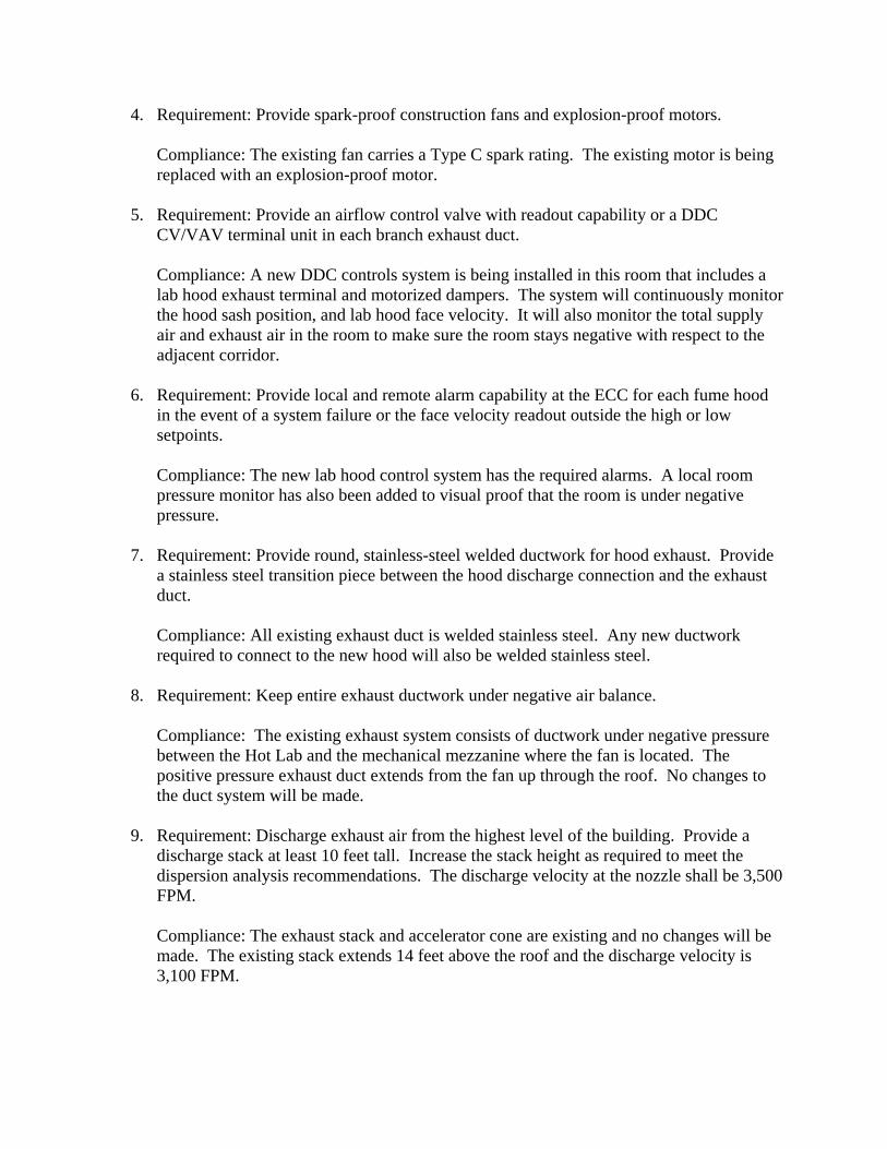
4. Requirement: Provide spark-proof construction fans and explosion-proof motors.
Compliance: The existing fan carries a Type C spark rating. The existing motor is being replaced with an explosion-proof motor.
5. Requirement: Provide an airflow control valve with readout capability or a DDC CV/VAV terminal unit in each branch exhaust duct.
Compliance: A new DDC controls system is being installed in this room that includes a lab hood exhaust terminal and motorized dampers. The system will continuously monitor the hood sash position, and lab hood face velocity. It will also monitor the total supply air and exhaust air in the room to make sure the room stays negative with respect to the adjacent corridor.
6. Requirement: Provide local and remote alarm capability at the ECC for each fume hood in the event of a system failure or the face velocity readout outside the high or low setpoints.
Compliance: The new lab hood control system has the required alarms. A local room pressure monitor has also been added to visual proof that the room is under negative pressure.
7. Requirement: Provide round, stainless-steel welded ductwork for hood exhaust. Provide a stainless steel transition piece between the hood discharge connection and the exhaust duct.
Compliance: All existing exhaust duct is welded stainless steel. Any new ductwork required to connect to the new hood will also be welded stainless steel.
8. Requirement: Keep entire exhaust ductwork under negative air balance.
Compliance: The existing exhaust system consists of ductwork under negative pressure between the Hot Lab and the mechanical mezzanine where the fan is located. The positive pressure exhaust duct extends from the fan up through the roof. No changes to the duct system will be made.
9. Requirement: Discharge exhaust air from the highest level of the building. Provide a discharge stack at least 10 feet tall. Increase the stack height as required to meet the dispersion analysis recommendations. The discharge velocity at the nozzle shall be 3,500 FPM.
Compliance: The exhaust stack and accelerator cone are existing and no changes will be made. The existing stack extends 14 feet above the roof and the discharge velocity is 3,100 FPM.

10. Requirement: Include the discharge air velocity pressure and the static pressure drop through the hood in the fan static pressure calculations.
Compliance: The fan is existing and the total exhaust air flow is not being modified. No static pressure calculations are required.
11. Requirement: Include recommended acoustic analysis measures to contain the fan noise traveling back to the exhaust fan in the system design.
Compliance: The fan and exhaust system is existing. No acoustical analysis is required or provided.
12. Requirement: Do not attempt heat recovery from exhaust ducts of fume hoods.
Compliance: There is no heat recovery on the existing exhaust system.
13. Requirement: Do not install fume hood exhaust ducts in the same shafts that environmental ducts are housed. See NFPA 90A for additional information.
Compliance: The existing exhaust duct is not in a shaft that houses environmental ducts. No action is required.
14. Requirement: Do not install fire dampers in fume hood exhaust ducts.
Compliance: There are not fire dampers in the existing fume hood exhaust duct.
15. Requirement: The designer shall verify the project-specific filtration requirements for the Radioisotope hood exhaust air system in consultation with the end-users and the Radiation Safety Officer. The filtration requirements depend on the use/quantity and type of isotopes used and may require MERV 17 (HEPA) filter, or a combination of MERV 17 (HEPA) and a charcoal filter, or no filters at all.
Compliance: The Radiation Safety Officer has determined that no filtration is required.
Plumbing No plumbing work is required in the scope of this project. Fire Protection No fire protection work is required in the scope of this project.


Technical Specification Sheet Document No. 149-996
June 23, 2011
Lab and Pressurized Room Controllers with Off-board Air Modules
Siemens Industry, Inc.
Page 1 of 4
Figure 1. Lab Controller Module.
Figure 2. Off-board Air Module 550-818B.
Description
The APOGEE® Automation System Laboratory Room Controllers and Room Pressurization Controllers are available on a new hardware platform. The Lab Controller Module (LCM) uses the Off-board Air Module (OAM) to measure airflow for standard and custom pressurized room control applications.
Lab Controller Module
The LCM (Figure 1) operates as an independent, stand-alone DDC controller and can be connected on the Floor Level Network (FLN) with the APOGEE® Automation System. The LCM includes the largest physical point count of any APOGEE FLN device. Not all physical points are used in all applications.
Off-board Air Module
The OAM (Figure 2) contains the air velocity sensor (a specialized differential pressure transducer), V/F conversion circuitry and solenoid for auto-zero function. Advanced digital signal processing produces a highly accurate reading of even the noisiest flow signals. The auto-zero solenoid connects to the air velocity pressure transducer's inlet ports to enable automatic periodic re-calibration. This re-calibration ensures accurate, drift-free airflow measurement. Automatic re-calibration of the differential pressure transducers occurs upon system power-up and when airflows are stable with frequency selectable from 1 to 6 times a day.
Page 2 of 4
Siemens Industry, Inc.
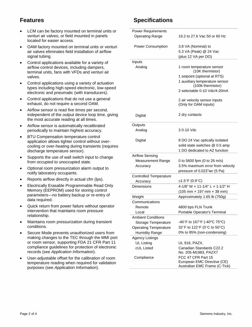
Features
LCM can be factory mounted on terminal units or venturi air valves, or field mounted in panels located for easier access.
OAM factory mounted on terminal units or venturi air valves eliminates field installation of airflow signal tubing.
Control applications available for a variety of airflow control devices, including dampers, terminal units, fans with VFDs and venturi air valves.
Control applications using a variety of actuation types including high-speed electronic, low-speed electronic and pneumatic (with transducers).
Control applications that do not use a general exhaust, do not require a second OAM.
Airflow sensor is read five times per second, independent of the output device loop time, giving the most accurate reading at all times.
Airflow sensor is automatically recalibrated periodically to maintain highest accuracy.
BTU Compensation temperature control application allows tighter control without over-cooling or over-heating during transients (requires discharge temperature sensor).
Supports the use of wall switch input to change from occupied to unoccupied state.
Optional room pressurization alarm output to notify laboratory occupants.
Reports airflow directly in actual cfm (lps). Electrically Erasable Programmable Read Only
Memory (EEPROM) used for storing control parameters—no battery backup or re-entry of data required.
Quick return from power failure without operator intervention that maintains room pressure relationship.
Maintains room pressurization during transient conditions.
Secure Mode prevents unauthorized users from making changes to the TEC through the MMI port or room sensor, supporting FDA 21 CFR Part 11 compliance guidelines for protection of electronic records (see Application Information).
User-adjustable offset for the calibration of room temperature reading when required for validation purposes (see Application Information).
Specifications
Power Requirements Operating Range Power Consumption
19.2 to 27.6 Vac 50 or 60 Hz 3.8 VA (Nominal) to 5.3 VA (Peak) @ 24 Vac (plus 12 VA per DO)
Inputs Analog
Digital
1 room temperature sensor (10K thermistor) 1 setpoint (optional at RTS) 1 auxiliary temperature sensor (100k thermistor) 2 selectable 0-10 Vdc/4-20mA 2 air velocity sensor inputs (Only for OAM inputs) 2 dry contacts
Outputs Analog Digital
3 0-10 Vdc 8 DO 24 Vac optically isolated solid state switches @ 0.5 amp 1 DO dedicated to AZ function
Airflow Sensing Measurement Range Accuracy
0 to 5600 fpm (0 to 26 m/s) 3.5% maximum error from velocity pressure of 0.023‖wc (5 Pa)
Controlled Temperature Accuracy
1.5 F (0.9 C)
Dimensions 4-1/8" W × 11-1/4" L × 1-1/2" H (105 mm × 197 mm × 38 mm)
Weight Approximately 1.65 lb (750g) Communications Remote Local
4800 bps FLN Trunk Portable Operator's Terminal
Ambient Conditions Storage Temperature Operating Temperature Humidity Range
-40 F to 167 F (-40 C 75 C) 32 F to 122 F (0 C to 50 C) 0% to 95% (non-condensing)
Agency Listings UL Listing cUL Listed
Compliance
UL 916, PAZX, Canadian Standards C22.2 No. 205-M1983, PAZX7 FCC 47 CFR Part 15 European EMC Directive (CE) Australian EMC Frame (C-Tick)

Siemens Industry, Inc.
Page 3 of 4
Application Information
LCM P/N Application Airflow Control Temperature Control
Application Notes Device Output Type Application Output
550-767C
2620
Venturi High-speed Modulating
Room Temp Sensor
0-10V
Flow-Tracking, compatible with VAV fume hood control. OCC and UOC states have separate, selectable: >Differential Flow Setpoint >VAV or CAV Temp Control Mode Room Temperature Offset for single-point calibration and SECURE MODE for Part 11 compliance solution.
2626 BTU Comp [Discharge Temp Req’d]
550-767D
2622
Venturi Low-speed Modulating
Room Temp Sensor
0-10V
Flow-Tracking, compatible with CV2 fume hood control. OCC and UOC states have separate, selectable: >Differential Flow Setpoint >VAV or CAV Temp Control Mode Room Temperature Offset for single-point calibration and SECURE MODE for Part 11 compliance solution.
2628 BTU Comp [Discharge Temp Req’d]
550-767E
2621
Damper High-speed 3-state
Room Temp Sensor
0-10V
Flow-Tracking, compatible with VAV fume hood control. OCC and UOC states have separate, selectable: >Differential Flow Setpoint >VAV or CAV Temp Control Mode Room Temperature Offset for single-point calibration and SECURE MODE for Part 11 compliance solution.
2627 BTU Comp [Discharge Temp Req’d]
550-767F
2623
Damper Low-speed 3-state
Room Temp Sensor
0-10V
Flow-Tracking, compatible with CV2 fume hood control. OCC and UOC states have separate, selectable: >Differential Flow Setpoint >VAV or CAV Temp Control Mode Room Temperature Offset for single-point calibration and SECURE MODE for Part 11 compliance solution.
2629 BTU Comp [Discharge Temp Req’d]
550-767G
2624 Damper supply Venturi exhaust
Low-speed Modulating / Low-speed
3-state
Room Temp Sensor
0-10V
Flow-Tracking, compatible with CV2 fume hood control. OCC and UOC states have separate, selectable: >Differential Flow Setpoint >VAV or CAV Temp Control Mode Room Temperature Offset for single-point calibration and SECURE MODE for Part 11 compliance solution.
2630 BTU Comp [Discharge Temp Req’d]
NOTE: Setpoint hardware adapter is required when using 10K duct sensor in place of room temperature sensor.
Information in this document is based on specifications believed correct at the time of publication. The right is reserved to make changes as design improvements are introduced. APOGEE and Insight are registered trademarks of Siemens Industry, Inc. Other product or company names mentioned herein may be the trademarks of their respective owners. © 2010 Siemens Industry, Inc.
Siemens Industry, Inc. Building Technologies Division 1000 Deerfield Parkway Buffalo Grove, IL 60089-4513 USA +1-847-215-1000
Your feedback is important to us. If you have comments about this document, please send them to
Document No. 149-996 Printed in the USA
Page 4 of 4
Application Information
LCM P/N Application Airflow Control Temperature Control
Application Notes Device
Output Type
Application Output
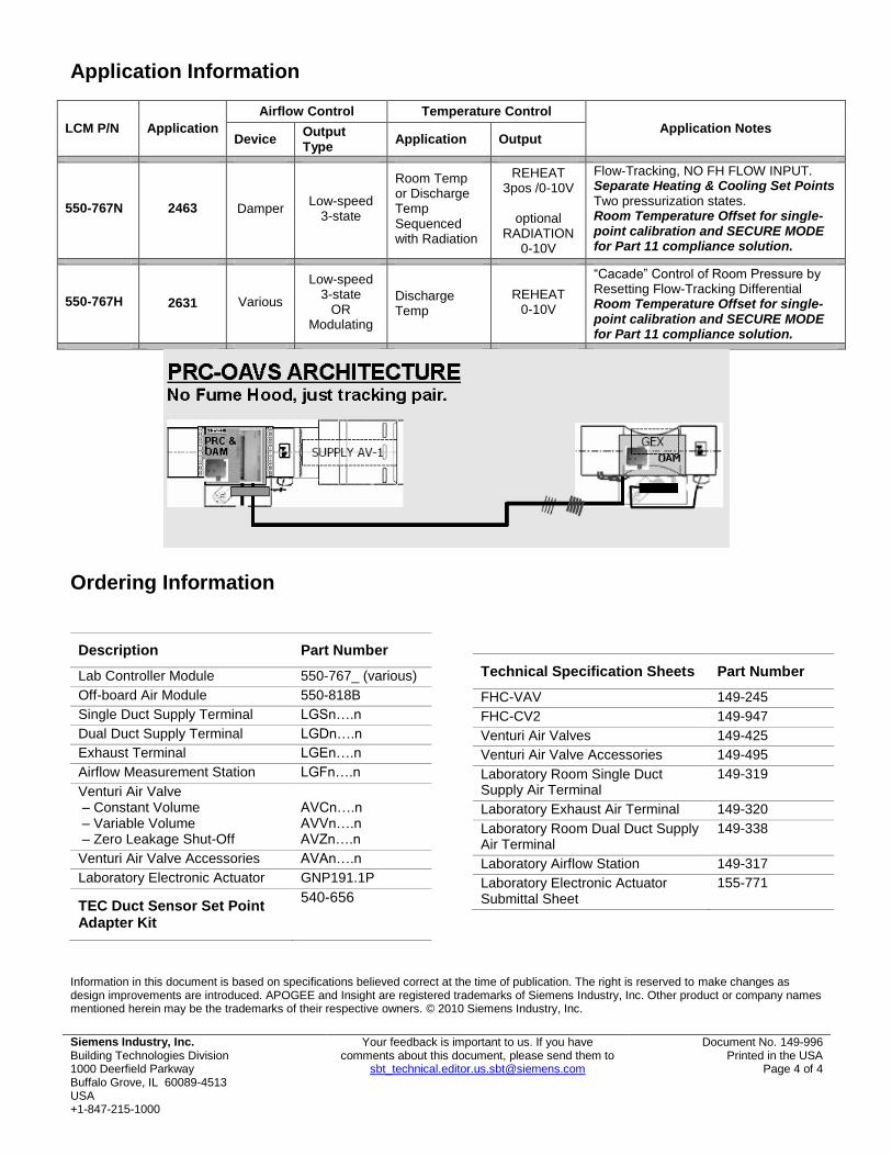
550-767N 2463 Damper Low-speed 3-state
Room Temp or Discharge Temp Sequenced with Radiation
REHEAT 3pos /0-10V
optional
RADIATION 0-10V
Flow-Tracking, NO FH FLOW INPUT. Separate Heating & Cooling Set Points Two pressurization states. Room Temperature Offset for single-point calibration and SECURE MODE for Part 11 compliance solution.
550-767H 2631 Various
Low-speed 3-state
OR Modulating
Discharge Temp
REHEAT 0-10V
―Cacade‖ Control of Room Pressure by Resetting Flow-Tracking Differential Room Temperature Offset for single-point calibration and SECURE MODE for Part 11 compliance solution.
Ordering Information
Description Part Number
Lab Controller Module 550-767_ (various) Off-board Air Module 550-818B Single Duct Supply Terminal LGSn….n Dual Duct Supply Terminal LGDn….n Exhaust Terminal LGEn….n Airflow Measurement Station LGFn….n Venturi Air Valve – Constant Volume – Variable Volume – Zero Leakage Shut-Off
AVCn….n AVVn….n AVZn….n
Venturi Air Valve Accessories AVAn….n Laboratory Electronic Actuator GNP191.1P
TEC Duct Sensor Set Point Adapter Kit
540-656
Technical Specification Sheets Part Number
FHC-VAV 149-245 FHC-CV2 149-947 Venturi Air Valves 149-425 Venturi Air Valve Accessories 149-495 Laboratory Room Single Duct Supply Air Terminal
149-319
Laboratory Exhaust Air Terminal 149-320 Laboratory Room Dual Duct Supply Air Terminal
149-338
Laboratory Airflow Station 149-317 Laboratory Electronic Actuator Submittal Sheet
155-771

Technical Specification SheetDocument No. 149-269P25
March, 1 2007
1Patent Numbers 5,090,304, 5,347,754 Siemens Building Technologies, Inc.
Page 1 of 2
UniTrak Fume Hood Sash Sensors
Specifications Sensing Range 0" to 85" (0 cm to 218cm) Resistance 96K Ω/ft Expected Life >1,000,000 cycles Ambient Conditions Storage Temperature Operating Temperature Operating Humidity
-40°F to 167°F (-40°C to 75°C) 0°F to 120°F (-20°C to 50°C) 20% to 80% rh non-condensing
Table 1. Materials of Construction.
Bill of Materials Construction Linkage Stainless Steel, Type 316 Actuator Block Assembly Stainless Steel, Type 440, 304,
302, and 18-8, PVC Adhesive Acrylic Sensor Connector Plastic, Nylon 6/6 Connector Plastic, Nylon 6/6 Cable Teflon Coated Sensor Strip Polyester Film Sensor Track Rigid PVC Type II Sensor Shield Rigid PVC Type II
Ordering Information
Vertical Sensor Kits * Description Installed Product Part Number
30 (762) 33.3 (846) 546-00490 32 (813) 35.3 (897) 546-00489 35 (889) 39.3 (998) 546-00488 40 (1016) 40.3 (1024) 546-00487 44 (1118) 48.3 (1227) 546-00486 53 (1346) 57.3 (1455) 546-00485 71 (1803) 75.3 (1913) 546-00484 85 (2159) 89.8 (2281) 546-00443
*Vertical Kits include 1 Unitrak with sensor, 1 sash actuator car, 2 straight linkages, and 1 sash sensor shield.
Horizontal Sensor Kits** Description Installed Product Part Number
34 (863.6) 39.3 (998) 546-00495 43 (1092) 48.3 (1227) 546-00493 52 (1321) 57.3 (1455) 546-00492 70 (1778) 75.3 (1913) 546-00491 84 (2134) 89.8 (2280) 546-00442
**Horizontal kits include 2 Unitraks with 2 sensors, 4 sash actuator cars, 5 straight linkages, and 2 sash sensor shields. Do not cut or trim horizontal sash traks. Functionality of one of the sash actuator cars will be lost.
Tools and Replacement Parts Description Product Part Number Spare Linkage Kit: Vertical 546-00215 Spare Linkage Kit: Horizontal 546-00494 Sensor Trim Toolkit 546-00041 Linkage Forming Tool 546-00558 Sash Sensor Cable 546-00175 Sash Sensor Actuator Kit 537-829

Information in this publication is based on current specifications. The company reserves the right to make changes in specifications and models as design improvements are introduced. Product or company names mentioned herein may be the trademarks of their respective owners. ©2007 Siemens Building Technologies, Inc. Siemens Building Technologies, Inc. 1000 Deerfield Parkway Buffalo Grove, IL 60089-4513
Your feedback is important to us. If you have comments about this document, please send them to
Sash Sensor Shields (included in kits or available as spares) Description Product Part Number
37.3 (947) 546-00565 46.3 (1176) 546-00566 55.3 (1405) 546-00567 73.3 (1862) 546-00568 87.8 (2230) 546-00569
Document No. 149-269 Country of Origin: US
Page 2 of 2
Document Description Document Number VAV FHC Specification Sheet 149-245P25 Unitrak Sensor Kit Installation Instructions
546-00449
Table 2. Fume Hood Sash Applications.
Sash Type Sash Kit Requirements Vertical/Multi-Vertical Sash
1 Vertical Kit per Vertical Sash
Horizontal Sash 1 Horizontal Kit per 4 Horizontal Sashes
Combination Sash 1 Vertical Kit per Vertical Sash, 1 Horizontal Kit per 4 Horizontal Sashes
Figure 3. Outside Installation.
Figure 4. Cable Placement.

Technical Specification Sheet Document No. 149-245P25
August 11, 2008
Siemens Building Technologies, Inc. Page 1 of 4
Fume Hood Controller Variable Air Volume (VAV)
Figure 1. Fume Hood Controller (SMT board), Enclosure
and Operator Display Panel
The Fume Hood Controller is an integral part of the APOGEE Automation System. The controller is a proven, patented stand-alone Direct Digital Control (DDC) system for Variable Air Volume (VAV) control of laboratory fume hoods. The controller maintains constant face velocity as the fume hood sash is raised and lowered. An Operator Display Panel provides the fume hood user with the face velocity readout, operating status of the hood, alarm horn, and an emergency purge function. The Fume Hood Controller operates independently and extends the benefits of DDC to an entire facility’s HVAC equipment.
Features
Controller
Constant face velocity fume hood operation. Maintains programmed minimum exhaust flow. Fully integrates with the APOGEE Automation
System controllers and software. True exhaust flow measurement used to position
the flow control device. Modular components, easy to install and service.
Program and calibration parameters are user defined or modified via the Laptop Terminal
PID closed loop control for all control devices Electrically Erasable Programmable Read Only
Memory (EEPROM) memory for setpoint and control parameters no battery needed
Supports multiple hood and sash configurations Supports damper, VFD and Venturi Air Valve
airflow control devices Surface Mount Technology for low electrical noise
Operator Display Panel
Continuous display of hood operating parameters using a large alpha-numeric display,
Colored hood status lights for normal (green), marginal (yellow), and alarm (red) conditions,
Purge push-button for activation of emergency operation mode,
Alarm horn for high and low face velocity and emergency purge indication
Easy to install and connect to the controller via a single cable and telephone type connectors.
Applications
Operating independently, or integrated with the APOGEE Automation System, the Fume Hood Controller may be configured for the following types of laboratory fume hood applications:
Single/Multi-Vertical Sash, Horizontal Sash and Combination Sash Bench top and Distillation type Fume Hoods,
Vertical and Horizontal Sash Walk-in Hoods, Damper or Venturi Air Valve control for manifold
exhaust systems or VFD for single hood fans Electronic or pneumatic damper actuators
Page 2 of 4 Siemens Building Technologies, Inc.
Description
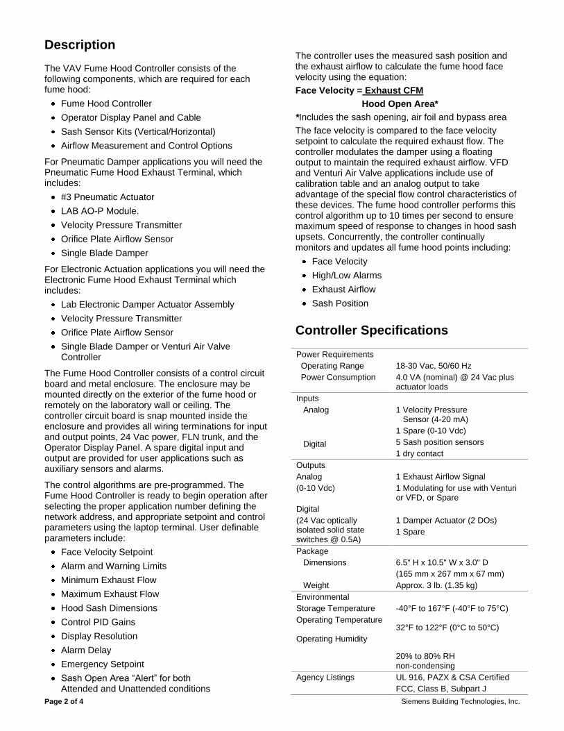
The VAV Fume Hood Controller consists of the following components, which are required for each fume hood:
Fume Hood Controller Operator Display Panel and Cable Sash Sensor Kits (Vertical/Horizontal) Airflow Measurement and Control Options
For Pneumatic Damper applications you will need the Pneumatic Fume Hood Exhaust Terminal, which includes:
#3 Pneumatic Actuator LAB AO-P Module. Velocity Pressure Transmitter Orifice Plate Airflow Sensor Single Blade Damper
For Electronic Actuation applications you will need the Electronic Fume Hood Exhaust Terminal which includes:
Lab Electronic Damper Actuator Assembly Velocity Pressure Transmitter Orifice Plate Airflow Sensor Single Blade Damper or Venturi Air Valve
Controller
The Fume Hood Controller consists of a control circuit board and metal enclosure. The enclosure may be mounted directly on the exterior of the fume hood or remotely on the laboratory wall or ceiling. The controller circuit board is snap mounted inside the enclosure and provides all wiring terminations for input and output points, 24 Vac power, FLN trunk, and the Operator Display Panel. A spare digital input and output are provided for user applications such as auxiliary sensors and alarms.
The control algorithms are pre-programmed. The Fume Hood Controller is ready to begin operation after selecting the proper application number defining the network address, and appropriate setpoint and control parameters using the laptop terminal. User definable parameters include:
Face Velocity Setpoint Alarm and Warning Limits Minimum Exhaust Flow Maximum Exhaust Flow Hood Sash Dimensions Control PID Gains Display Resolution Alarm Delay Emergency Setpoint Sash Open Area “Alert” for both
Attended and Unattended conditions
The controller uses the measured sash position and the exhaust airflow to calculate the fume hood face velocity using the equation: Face Velocity = Exhaust CFM
Hood Open Area*
*Includes the sash opening, air foil and bypass area The face velocity is compared to the face velocity setpoint to calculate the required exhaust flow. The controller modulates the damper using a floating output to maintain the required exhaust airflow. VFD and Venturi Air Valve applications include use of calibration table and an analog output to take advantage of the special flow control characteristics of these devices. The fume hood controller performs this control algorithm up to 10 times per second to ensure maximum speed of response to changes in hood sash upsets. Concurrently, the controller continually monitors and updates all fume hood points including:
Face Velocity High/Low Alarms Exhaust Airflow Sash Position
Controller Specifications
Power Requirements Operating Range Power Consumption
18-30 Vac, 50/60 Hz 4.0 VA (nominal) @ 24 Vac plus actuator loads
Inputs Analog Digital
1 Velocity Pressure Sensor (4-20 mA) 1 Spare (0-10 Vdc) 5 Sash position sensors 1 dry contact
Outputs Analog (0-10 Vdc) Digital (24 Vac optically isolated solid state switches @ 0.5A)
1 Exhaust Airflow Signal 1 Modulating for use with Venturi or VFD, or Spare 1 Damper Actuator (2 DOs) 1 Spare
Package Dimensions Weight
6.5" H x 10.5" W x 3.0" D (165 mm x 267 mm x 67 mm) Approx. 3 lb. (1.35 kg)
Environmental Storage Temperature Operating Temperature Operating Humidity
-40°F to 167°F (-40°F to 75°C) 32°F to 122°F (0°C to 50°C) 20% to 80% RH non-condensing
Agency Listings
UL 916, PAZX & CSA Certified FCC, Class B, Subpart J

Siemens Building Technologies, Inc. Page 3 of 4
CE, C-tick Communications Local Area Network (FLN trunk) Portable Operator’s Terminal
RS-485 4800 baud RS-232 1200 baud
Control Performance Speed of Response
1 second to flow change
Airflow Measurement Range Accuracy*
0 – 2.5" wc 3.0%
*Accuracy is shown in percent of Actual Airflow and includes differential pressure transmitter accuracy.
Operator Display Panel
The Fume Hood Controller Operator Display Panel (ODP) includes a custom designed package for visual and audible indication of fume hood operating conditions and push-buttons for emergency mode operation, alarm silence and user defined auxiliary functions. The panel is mounted on the fume hood in an easy to access location and will fit over an unused hood electrical box or over pre-drilled holes. RJ-11 type connectors provide termination to the Fume Hood Controller and for the Portable Operator’s Terminal. One Operator Display Panel is supported per Fume Hood Controller.
The Operator Display Panel supports the following functions:
Digital display of face velocity in FPM (MPS), Green, yellow and red status lights, Emergency purge push button, Alarm horn with silence push button, and Two auxiliary push buttons.
The face velocity display also indicates high and low alarm conditions, emergency purge activation, and diagnostic failure mode conditions when the controller is in the minimum flow mode. Face velocity FPM (MPS) display may be blanked as an option for applications where the user does not desire the face velocity reading.
Operator Display Panel Specifications
Face Velocity Display Range
0 fpm to 255 fpm (0.0 MPS to 1.3 MPS)
Display Resolution 1 fpm adjustable up to 255 fpm
Push-Buttons Switch inputs
1 Emergency Purge 1 Horn Silence 2 Momentary Auxiliary
Alarm Horn 85 dB @ 4" (10 cm) Dimensions 5.5" H x 3.125" W x 1.5" D
(140 mm x 80 mm x 39 mm) Weight 8 oz. (0.2 kg)
Fume Hood Controller Communication
Compatible with the Modular Building Controller (MBC), Mechanical Equipment Controller (MEC) and FLN Controller, up to 32 Fume Hood Controllers can be connected to each one of a field panel’s three FLN Trunks, for a total of 96 per field panel.
Operators can communicate with the Fume Hood Controller from any field panel on the system network. The APOGEE Automation System network does not require additional hardware to connect controllers. When Fume Hood Controllers are networked to an MBC, MEC or FLN Controller, all the APOGEE Automation System features available can utilize the Fume Hood Controller.
Portable Operator’s Terminal
The laptop computer serving as the Portable Operator’s Terminal can communicate with the Fume Hood Controller. The terminal connects to the controller via a plug-in jack on the ODP. The terminal can be used to remotely adjust setpoints, to troubleshoot and start up the system. The terminal uses full English language prompting for all functions, eliminating the need to remember coded commands.
Information in this document is based on specifications believed correct at the time of publication. The right is reserved to make changes as design improvements are introduced. APOGEE and Insight are registered trademarks of Siemens Building Technologies, Inc. Other product or company names mentioned herein may be the trademarks of their respective owners. © 2008 Siemens Building Technologies, Inc.
Siemens Building Technologies, Inc. 1000 Deerfield Parkway Buffalo Grove, IL 60089-4513
Your feedback is important to us. If you have comments about this document, please send them to
Document No. 149-245 Country of Origin: US
Page 4 of 4
Ordering Information
Description Part Number
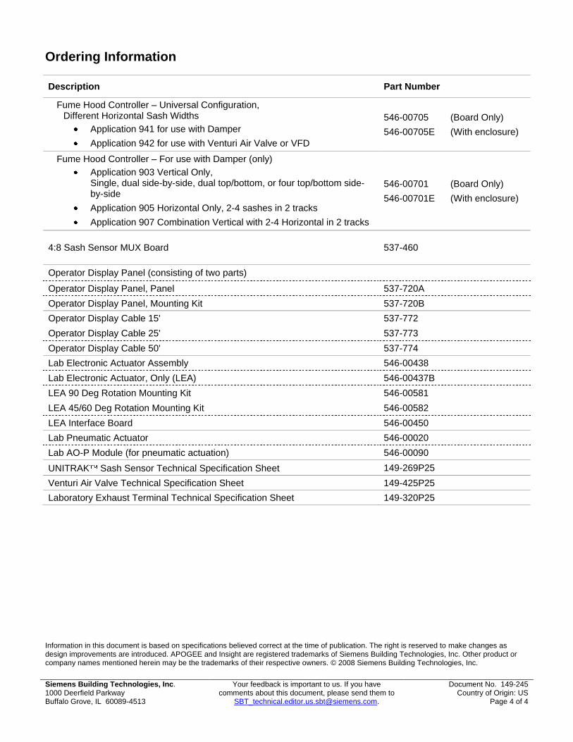
Fume Hood Controller – Universal Configuration, Different Horizontal Sash Widths
Application 941 for use with Damper Application 942 for use with Venturi Air Valve or VFD
546-00705 (Board Only) 546-00705E (With enclosure)
Fume Hood Controller – For use with Damper (only) Application 903 Vertical Only,
Single, dual side-by-side, dual top/bottom, or four top/bottom side-by-side
Application 905 Horizontal Only, 2-4 sashes in 2 tracks Application 907 Combination Vertical with 2-4 Horizontal in 2 tracks
546-00701 (Board Only) 546-00701E (With enclosure)
4:8 Sash Sensor MUX Board 537-460
Operator Display Panel (consisting of two parts)
Operator Display Panel, Panel 537-720A Operator Display Panel, Mounting Kit 537-720B Operator Display Cable 15' 537-772 Operator Display Cable 25' 537-773 Operator Display Cable 50' 537-774 Lab Electronic Actuator Assembly 546-00438 Lab Electronic Actuator, Only (LEA) 546-00437B LEA 90 Deg Rotation Mounting Kit 546-00581 LEA 45/60 Deg Rotation Mounting Kit 546-00582 LEA Interface Board 546-00450 Lab Pneumatic Actuator 546-00020 Lab AO-P Module (for pneumatic actuation) 546-00090 UNITRAK Sash Sensor Technical Specification Sheet 149-269P25 Venturi Air Valve Technical Specification Sheet 149-425P25 Laboratory Exhaust Terminal Technical Specification Sheet 149-320P25
Technical Specification Sheet Document No. 149-320P25
January 7, 2011
Siemens Industry, Inc Page 1 of 12
Laboratory Room Exhaust Air Terminal
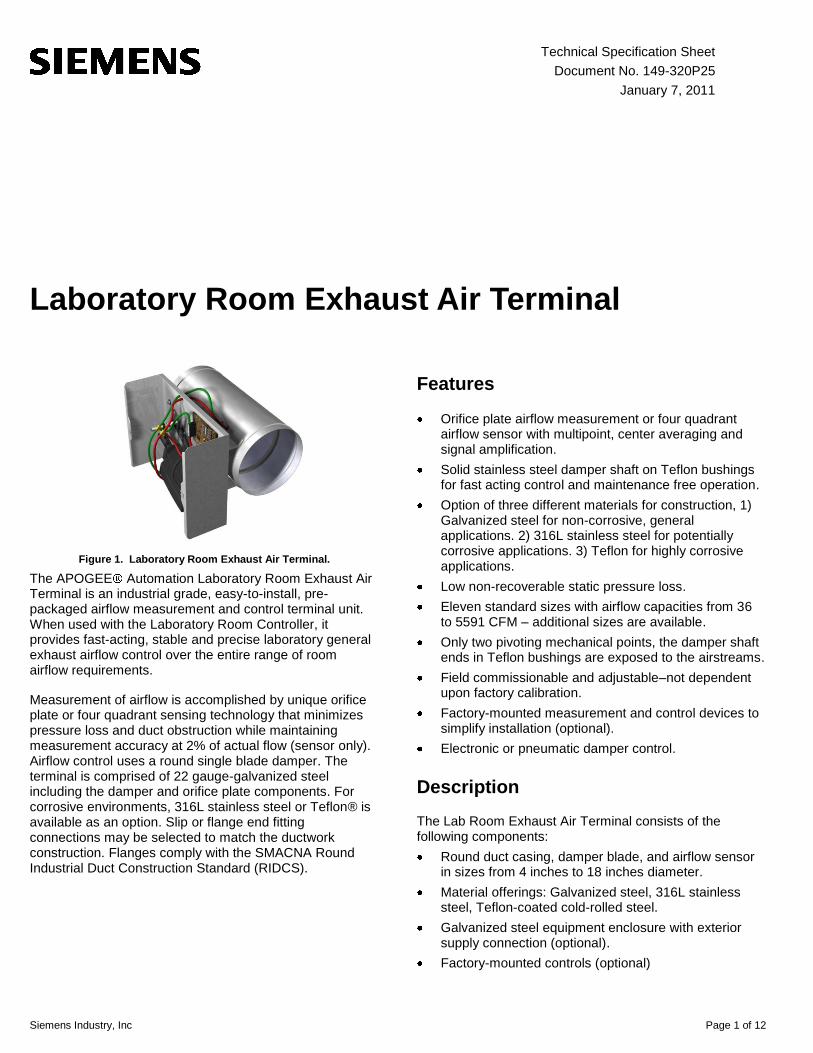
Figure 1. Laboratory Room Exhaust Air Terminal.
The APOGEE Automation Laboratory Room Exhaust Air Terminal is an industrial grade, easy-to-install, pre-packaged airflow measurement and control terminal unit. When used with the Laboratory Room Controller, it provides fast-acting, stable and precise laboratory general exhaust airflow control over the entire range of room airflow requirements.
Measurement of airflow is accomplished by unique orifice plate or four quadrant sensing technology that minimizes pressure loss and duct obstruction while maintaining measurement accuracy at 2% of actual flow (sensor only). Airflow control uses a round single blade damper. The terminal is comprised of 22 gauge-galvanized steel including the damper and orifice plate components. For corrosive environments, 316L stainless steel or Teflon® is available as an option. Slip or flange end fitting connections may be selected to match the ductwork construction. Flanges comply with the SMACNA Round Industrial Duct Construction Standard (RIDCS).
Features
Orifice plate airflow measurement or four quadrant airflow sensor with multipoint, center averaging and signal amplification.
Solid stainless steel damper shaft on Teflon bushings for fast acting control and maintenance free operation.
Option of three different materials for construction, 1) Galvanized steel for non-corrosive, general applications. 2) 316L stainless steel for potentially corrosive applications. 3) Teflon for highly corrosive applications.
Low non-recoverable static pressure loss. Eleven standard sizes with airflow capacities from 36
to 5591 CFM – additional sizes are available. Only two pivoting mechanical points, the damper shaft
ends in Teflon bushings are exposed to the airstreams. Field commissionable and adjustable–not dependent
upon factory calibration. Factory-mounted measurement and control devices to
simplify installation (optional). Electronic or pneumatic damper control.
Description
The Lab Room Exhaust Air Terminal consists of the following components: Round duct casing, damper blade, and airflow sensor
in sizes from 4 inches to 18 inches diameter. Material offerings: Galvanized steel, 316L stainless
steel, Teflon-coated cold-rolled steel. Galvanized steel equipment enclosure with exterior
supply connection (optional). Factory-mounted controls (optional)

Page 2 of 12 Siemens Industry, Inc.
Specifications
Materials (within air stream) – Standard
Construction A
22-gauge Galvanized steel casing, orifice & blade. Shaft is zinc-plated steel. Type A or B sensors available.
Construction B
20-gauge 316L stainless steel casing, orifice & blade. Shaft is solid stainless steel. Type A sensors only.
Construction C
Teflon-coated 18 ga. Cold-rolled Carbon Steel casing, orifice, blade, shaft, nuts, bolts. Type A sensors only.
Damper Shaft Teflon shaft bushings. 1/2-inch (1.27 cm) diameter, End marked with blade position
Flanges Comply with SMACNA RIDCS. Seam welded BEFORE coating for A or C code.
Materials (outside air stream) – Standard
Control Enclosure 18 gauge galvanized steel Pneumatic Tubing UL rated 94 V-2 fire retardant Pneumatic Fittings with enclosure only
Brass, dual barbed
Airflow Measurement
Sensor Type A Square edge orifice plate Two sets of averaging pressure taps Same material as duct casing
Sensor Type B Four quadrant, with 12 sensing points, center averaging and signal amplification
Accuracy
Flow Measurement ±2% of actual flow @ listed ranges (Sensor only. Does not include accuracy of controller or transmitter.)
Installation Requirements
Rigid duct of the same diameter 1 x duct diameters upstream from the sensor, or taper angle less than 30 deg, is required.
Airflow Control
Damper Blade Round, non-sealing single blade with 90 degree control
Environmental
Operating Temperature/% RH
40 to 120°F (4 to 50°C) 0 to 95% non-condensing
Storage Temperature/% RH
-10 to 150°F (-23 to 65°C) 0 to 95% non-condensing
Dimensions
Sizes See Figure 2 and Figure 3 Weight 20 to 32 lbs. (9.1 to 14.5 kg)

Siemens Industry, Inc. Page 3 of 12
Dimensions
Figure 2. Laboratory Room Exhaust Air Terminal with Orifice Flow Sensor.

Page 4 of 12 Siemens Industry, Inc.
Figure 3. Laboratory Exhaust Air Terminal with Multi-Point Flow Sensor.
Siemens Industry, Inc. Page 5 of 12
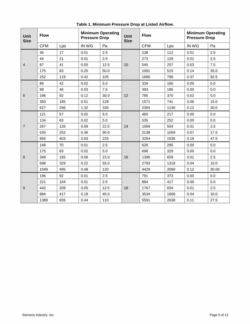
Table 1. Minimum Pressure Drop at Listed Airflow.
Unit Size
Flow Minimum Operating Pressure Drop Unit
Size Flow
Minimum Operating Pressure Drop
CFM Lps IN WG Pa CFM Lps IN WG Pa
4
36 17 0.01 2.5
10
238 112 0.01 2.5 44 21 0.01 2.5 273 129 0.01 2.5 87 41 0.05 12.5 545 257 0.03 7.5 175 83 0.20 50.0 1091 515 0.14 35.0 252 119 0.42 105 1686 796 0.37 92.5
6
89 42 0.02 5.0
12
339 160 0.00 0.0 98 46 0.03 7.5 393 185 0.00 0.0 196 92 0.12 30.0 785 370 0.02 5.0 393 185 0.51 128 1571 741 0.06 15.0 627 296 1.32 330 2394 1130 0.12 30.0
7
121 57 0.02 5.0
14
460 217 0.00 0.0 134 63 0.02 5.0 535 252 0.00 0.0 267 126 0.09 22.5 1069 504 0.01 2.5 535 252 0.36 90.0 2138 1009 0.07 17.5 855 403 0.93 233 3254 1536 0.19 47.5
8
148 70 0.01 2.5
16
626 295 0.00 0.0 175 83 0.02 5.0 698 329 0.00 0.0 349 165 0.06 15.0 1396 659 0.01 2.5 698 329 0.22 55.0 2793 1318 0.04 10.0 1049 495 0.48 120 4429 2090 0.12 30.00
9
196 92 0.01 2.5
18
791 373 0.00 0.0 221 104 0.01 2.5 884 417 0.00 0.0 442 209 0.05 12.5 1767 834 0.01 2.5 884 417 0.18 45.0 3534 1668 0.04 10.0 1389 655 0.44 110 5591 2638 0.11 27.5

Page 6 of 12 Siemens Industry, Inc.
Table 2. Exhaust Terminal Casing Leakage in CFM.
LGE Casing Leakage (Per ASHRAE 130-1996)
Imperial Units (CFM, Inches Water)
Unit Size 1” WC 3.0”WC 6.0”WC Unit Size 1.0” WC 3.0” WC 6.0”WC
4 0 1 3 10 1 3 4 6 0 1 3 11 / 12 1 2 3 7 1 2 4 14 1 3 5 8 1 2 4 16 1 3 5 9 1 2 4 18 1 3 5
Metric Units (Lps, Pascals)
Unit Size
250 Pa 750 Pa 1500 Pa Unit Size 250 Pa 750 Pa 1500 Pa
4 0.0 0.5 1.4 10 0.5 1.4 1.9 6 0.0 0.5 1.4 11 / 12 0.5 0.9 1.4 7 0.5 0.9 1.9 14 0.5 1.4 2.4 8 0.5 0.9 1.9 16 0.5 1.4 2.4 9 0.5 0.9 1.9 18 0.5 1.4 2.4
Table 3. Exhaust Terminal Damper Leakage in CFM.
LGE Closed Blade Leakage, No Seals (Per ASHRAE 130-1996)
Imperial Units (CFM, Inches Water)
Unit Size 1.0” WC 3.0”WC 6.0”WC Unit Size 1.0” WC 3.0” WC 6.0”WC
4 13 20 25 10 67 110 135 6 31 50 63 11/12 72 144 168 7 39 58 77 14 98 195 228 8 42 73 94 16 133 266 310 9 56 94 111 18 112 280 335
Metric Units (Lps, Pascals)
Unit Size 250 Pa 750 Pa 1500 Pa Unit Size 250 Pa 750 Pa 1500 Pa
4 6 9 12 10 32 52 64 6 15 24 30 11 / 12 34 68 79 7 18 27 36 14 46 92 108 8 20 34 44 16 63 126 146 9 26 44 52 18 53 132 158
LGE Blade Seal Leakage (VOLARA; Per ASHRAE 130-1996)
Imperial Units (CFM, Inches Water)
Unit Size 1” WC 3.0”WC 6.0”WC Unit Size 1.0” WC 3.0” WC 6.0”WC
4 0 1 3 10 1 3 4 6 0 1 3 11/12 1 2 4 7 1 2 3 14 1 3 5 8 1 2 3 16 1 3 5 9 1 2 4 18 1 3 5
Metric Units (Lps, Pascals)
Unit Size 250 Pa 750 Pa 1500 Pa Unit Size 250 Pa 750 Pa 1500 Pa
4 0.0 0.5 1.4 10 0.5 1.4 1.9 6 0.0 0.5 1.4 11 / 12 0.5 0.9 1.9 7 0.5 0.9 1.9 14 0.5 1.4 2.4 8 0.5 0.9 1.9 16 0.5 1.4 2.4 9 0.5 0.9 1.9 18 0.5 1.4 2.4

Siemens Industry, Inc. Page 7 of 12
Table 4. Flow Range for Orifice Air Flow Sensor.
Flow Range for Sensor “A”
Inlet Size Maximum Flow @ 1.0” dp Minimum Flow @ 0.02” dp Flow Sensor Inlet Area Flow Coefficient CFM. Lps CFM Lps SQ.FT M2
4 252 119 36 17 0.087 0.008 0.721 6 627 296 89 42 0.196 0.018 0.797 7 857 404 121 57 0.267 0.025 0.801 8 1049 495 148 70 0.349 0.032 0.750 9 1389 656 196 93 0.442 0.041 0.785
10 1686 796 238 112 0.545 0.051 0.772 11 2054 969 290 137 0.785 0.073 0.653 12 2394 1130 339 160 0.785 0.073 0.761 14 3254 1536 460 217 1.069 0.099 0.760 16 4429 2090 626 295 1.396 0.130 0.792 18 5591 2639 791 373 1.767 0.164 0.790
Table 5. Flow Range for Sensor – Center-Averaging Multi-Port.
Note: The multi-point flow sensor option is not available for unit sizes 4, 11, and 18.
Flow Range for Sensor “B”
Inlet Size Maximum Flow @ 1.0” dp Minimum Flow @ 0.02” dp Flow Sensor Inlet Area Flow Coefficient CFM. Lps CFM Lps SQ.FT M2
6 468 221 66 31 0.196 0.018 0.596 7 673 318 95 45 0.267 0.025 0.629 8 923 436 126 59 0.349 0.032 0.660 9 1155 545 163 77 0.442 0.041 0.652
10 1487 702 210 99 0.545 0.051 0.681 12 2141 1010 303 143 0.785 0.073 0.681 14 3045 1437 431 203 1.069 0.099 0.711 16 4074 1923 576 272 1.396 0.130 0.729
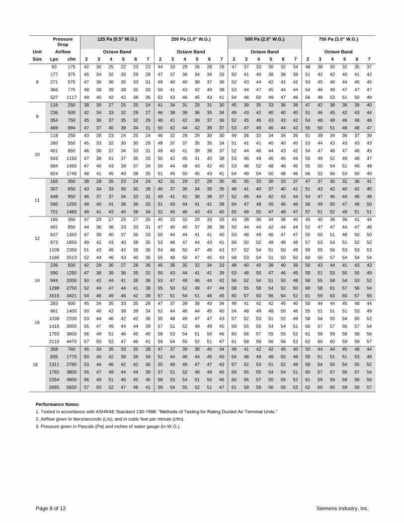
Table 6. Radiated Sound Data for Exhaust Terminal. Sound Power Levels, Lw dB, re 10^-12 Watts.
Pressure Drop
125 Pa (0.5" W.G.) 250 Pa (1.0" W.G.) 500 Pa (2.0" W.G.) 750 Pa (3.0" W.G.)
Unit Airflow Octave Band Octave Band Octave Band Octave Band
Size Lps cfm 2 3 4 5 6 7 2 3 4 5 6 7 2 3 4 5 6 7 2 3 4 5 6 7
4
35 75 51 29 27 22 19 17 51 32 30 27 24 24 52 36 33 31 29 31 52 38 35 34 32 35 71 150 52 34 36 31 27 23 52 38 40 35 32 30 53 41 43 40 37 36 53 43 45 42 40 41 106 225 52 38 42 36 31 26 53 41 45 41 36 33 53 45 49 45 41 40 53 47 51 48 44 44
132 279 53 39 45 39 33 28 53 43 48 43 39 35 53 46 52 48 44 42 54 48 54 50 47 46
6
59 125 41 27 23 21 20 20 44 31 27 26 26 26 46 35 32 31 32 33 48 38 34 34 35 37 118 250 44 33 30 29 26 25 46 37 35 34 31 31 49 41 39 39 37 38 50 43 42 41 40 42 177 375 45 36 35 33 29 28 48 40 39 38 35 34 50 44 44 43 40 41 52 46 46 46 44 44
236 500 46 38 38 36 31 30 49 42 42 41 37 36 51 46 47 46 43 43 53 49 50 49 46 47 296 628 47 40 40 39 33 32 50 44 45 44 39 38 52 48 49 49 44 44 54 50 52 51 48 48
7
71 150 43 28 22 21 22 19 45 31 26 25 26 24 46 34 30 29 31 29 47 36 33 31 34 33 142 300 46 33 29 29 27 24 47 36 33 33 32 29 49 39 37 36 37 35 50 41 40 39 40 38
212 450 47 36 33 33 30 27 49 39 37 37 35 32 50 42 42 41 40 38 51 43 44 43 43 41 284 601 48 38 36 37 33 29 50 41 40 40 37 34 51 44 45 44 42 40 52 46 47 46 45 43
Page 8 of 12 Siemens Industry, Inc.
Pressure Drop
125 Pa (0.5" W.G.) 250 Pa (1.0" W.G.) 500 Pa (2.0" W.G.) 750 Pa (3.0" W.G.)
Unit Airflow Octave Band Octave Band Octave Band Octave Band
Size Lps cfm 2 3 4 5 6 7 2 3 4 5 6 7 2 3 4 5 6 7 2 3 4 5 6 7
8
83 175 42 30 25 22 23 23 44 33 29 26 28 28 47 37 33 30 32 34 48 38 35 32 35 37 177 375 45 34 32 30 29 28 47 37 36 34 34 33 50 41 40 38 38 39 51 42 42 40 41 42 271 575 47 36 36 35 33 31 49 40 40 38 37 36 52 43 44 42 42 42 53 45 46 44 45 45
366 775 48 38 39 38 35 33 50 41 43 42 40 38 53 44 47 45 44 44 54 46 49 47 47 47 527 1117 49 40 42 42 38 35 52 43 46 45 43 41 54 46 50 49 47 46 56 48 53 51 50 49
9
118 250 38 30 27 25 25 24 41 34 31 29 31 30 45 39 35 33 36 36 47 42 38 36 39 40 236 500 42 34 33 32 29 27 46 38 38 36 35 34 49 43 42 40 40 40 51 46 45 42 43 44
354 750 45 36 37 35 32 29 48 41 42 39 37 36 52 45 46 43 43 42 54 48 48 46 46 46 469 994 47 37 40 38 34 31 50 42 44 42 39 37 53 47 49 46 44 43 55 50 51 48 48 47
10
118 250 43 28 23 24 25 24 46 32 28 29 30 30 49 36 32 34 34 35 51 39 34 36 37 39 260 550 45 33 32 30 30 29 48 37 37 35 35 34 51 41 41 40 40 40 53 44 43 43 43 43
401 850 46 36 37 34 33 31 49 40 41 39 38 37 52 44 46 44 43 42 54 47 48 47 46 45 543 1150 47 38 41 37 35 33 50 42 45 41 40 38 53 46 49 46 45 44 55 49 52 49 48 47 684 1450 47 40 43 39 37 34 50 44 48 43 42 40 53 48 52 48 46 45 55 50 54 51 49 48 824 1745 48 41 45 40 38 35 51 45 50 45 43 41 54 49 54 50 48 46 56 52 56 53 50 49
11
165 350 38 28 26 23 24 24 42 31 29 27 29 30 45 35 33 30 33 37 47 37 35 32 36 41 307 650 43 34 33 30 30 28 46 37 36 34 35 35 49 41 40 37 40 41 51 43 42 40 42 45 448 950 46 37 37 34 33 31 49 41 41 38 38 37 52 45 44 42 43 44 54 47 46 44 46 48 590 1250 48 40 41 38 36 33 51 43 44 41 41 39 54 47 48 45 46 46 56 49 50 47 49 50
701 1485 49 41 43 40 38 34 52 45 46 43 43 40 55 49 50 47 48 47 57 51 52 49 51 51
12
165 350 37 29 27 25 27 26 40 33 32 29 33 33 43 38 36 34 38 40 45 40 38 36 41 44 401 850 44 36 36 33 33 31 47 40 40 37 38 38 50 44 44 42 44 44 52 47 47 44 47 48 637 1350 47 39 40 37 36 33 50 44 44 41 41 40 53 48 49 46 47 47 55 50 51 48 50 50
873 1850 49 42 43 40 38 35 53 46 47 44 43 41 56 50 52 49 48 48 57 53 54 51 52 52 1109 2350 51 43 45 42 39 36 54 48 50 47 45 43 57 52 54 51 50 49 59 55 56 53 53 53 1186 2513 52 44 46 43 40 36 55 48 50 47 45 43 58 53 54 51 50 50 60 55 57 54 54 54
14
236 500 42 29 30 27 28 26 45 35 35 32 34 33 48 40 40 38 40 39 50 43 44 41 43 43
590 1250 47 38 39 36 35 32 50 43 44 41 41 39 53 48 50 47 46 45 55 51 53 50 50 49 944 2000 50 42 44 41 38 36 53 47 49 46 44 42 56 52 54 51 50 48 58 55 58 54 53 52 1298 2750 52 44 47 44 41 38 55 50 52 49 47 44 58 55 58 54 52 50 60 58 61 57 56 54 1615 3421 54 46 49 46 42 39 57 51 54 51 48 45 60 57 60 56 54 52 61 59 63 60 57 55
16
283 600 45 34 35 33 35 28 47 37 39 38 40 34 49 41 42 42 45 40 50 44 44 45 48 44 661 1400 50 40 42 39 39 34 52 44 46 44 45 40 54 48 49 48 50 46 55 51 51 51 53 49 1038 2200 53 44 46 42 42 36 55 48 49 47 47 43 57 52 53 51 52 49 58 54 55 54 55 52 1416 3000 55 47 49 44 44 39 57 51 52 49 49 45 59 55 55 54 54 51 60 57 57 56 57 54
1793 3800 56 49 51 46 45 40 58 53 54 51 50 46 60 56 57 55 55 52 61 59 59 58 58 56 2110 4470 57 50 52 47 46 41 59 54 55 52 51 47 61 58 59 56 56 53 62 60 60 59 59 57
18
358 760 45 34 35 33 35 28 47 37 39 38 40 34 49 41 42 42 45 40 50 44 44 45 48 44 835 1770 50 40 42 39 39 34 52 44 46 44 45 40 54 48 49 48 50 46 55 51 51 51 53 49
1311 2780 53 44 46 42 42 36 55 48 49 47 47 43 57 52 53 51 52 49 58 54 55 54 55 52 1792 3800 55 47 49 44 44 39 57 51 52 49 49 45 59 55 55 54 54 51 60 57 57 56 57 54 2264 4800 56 49 51 46 45 40 58 53 54 51 50 46 60 56 57 55 55 52 61 59 59 58 58 56 2665 5650 57 50 52 47 46 41 59 54 55 52 51 47 61 58 59 56 56 53 62 60 60 59 59 57
Performance Notes:
1. Tested in accordance with ASHRAE Standard 130-1996: ―Methods of Testing for Rating Ducted Air Terminal Units.‖ 2. Airflow given in liters/seconds (L/s); and in cubic feet per minute (cfm). 3. Pressure given in Pascals (Pa) and inches of water gauge (in W.G.).

Siemens Industry, Inc. Page 9 of 12
Table 7. Discharge Sound Data for Exhaust Terminal. Sound Power Levels, Lw dB, re 10^-12 Watts.
125 Pa (0.5" W.G.) 250 Pa (1.0" W.G.) 500 Pa (2.0" W.G.) 750 Pa (3.0" W.G.)
Unit Airflow Octave Band Octave Band Octave Band Octave Band
Size Lps cfm 2 3 4 5 6 7 2 3 4 5 6 7 2 3 4 5 6 7 2 3 4 5 6 7
4
35 75 46 43 45 43 43 38 51 49 50 49 49 45 56 54 55 54 55 53 58 58 58 58 58 57 71 150 52 50 52 50 49 43 56 56 57 56 55 50 61 61 62 61 61 58 64 65 65 64 65 62 106 225 55 54 56 54 53 46 60 60 61 60 59 54 65 65 67 65 65 61 67 69 70 68 68 65 132 279 57 56 59 56 54 48 62 62 64 62 60 55 66 67 69 67 66 63 69 71 72 71 70 67
6
59 125 47 40 43 45 43 39 51 45 48 50 49 45 56 50 52 54 55 52 59 53 55 57 59 56 118 250 54 48 50 51 48 44 58 53 55 55 54 50 63 58 60 60 60 57 66 61 62 63 63 61 177 375 58 53 54 54 50 47 62 58 59 59 56 53 67 63 64 64 63 60 70 66 67 67 66 64 236 500 61 56 57 56 52 49 65 61 62 61 58 55 70 66 67 66 64 62 73 69 70 69 68 66
296 628 63 58 59 58 54 50 68 64 64 63 60 57 72 69 69 68 66 64 75 72 72 71 70 68
7
71 150 43 38 41 40 39 36 48 42 45 45 45 43 53 47 50 50 51 50 55 50 53 52 54 54 142 300 51 46 48 48 45 42 56 51 53 52 51 49 61 56 58 57 57 55 64 58 60 60 60 59 212 450 55 51 53 52 49 45 60 56 57 57 55 52 65 61 62 61 61 59 68 63 65 64 64 63
284 601 59 55 56 55 52 48 64 59 61 60 58 54 69 64 65 64 63 61 72 67 68 67 67 65
8
83 175 43 38 40 43 45 38 48 43 45 47 51 45 53 48 50 52 57 53 56 50 53 55 60 58 177 375 52 47 49 50 50 44 57 52 53 54 56 52 62 57 58 59 62 59 64 59 61 62 65 64 271 575 57 53 53 54 53 47 61 57 58 58 59 55 66 62 63 63 64 63 69 64 66 66 68 67
366 775 60 56 57 57 55 49 65 61 61 61 61 57 70 65 66 66 66 65 73 68 69 69 70 70 527 1117 64 61 61 60 57 52 69 65 66 65 63 60 74 70 70 69 69 68 77 72 73 72 72 73
9
118 250 46 41 42 43 42 34 51 46 47 48 48 41 56 51 51 53 54 48 59 54 54 56 57 52 236 500 53 48 50 50 48 41 58 53 55 55 53 48 63 58 59 59 59 55 66 61 62 62 63 59
354 750 58 53 55 54 51 45 63 58 59 58 57 52 68 63 64 63 62 59 71 66 66 66 66 63 469 994 60 56 58 56 53 47 66 61 62 61 59 54 71 66 67 66 65 61 74 69 69 69 68 66
10
118 250 45 41 42 41 41 40 50 46 47 47 47 47 54 51 51 52 52 54 57 54 54 55 56 58 260 550 54 50 51 48 47 45 59 55 55 53 53 52 63 59 60 59 59 59 66 62 62 62 63 63
401 850 59 54 55 52 51 48 64 59 60 57 57 55 68 64 65 62 63 62 71 67 67 66 66 65 543 1150 63 58 59 54 54 50 67 62 63 60 60 57 71 67 68 65 66 64 74 70 71 68 69 67 684 1450 65 60 61 56 56 52 70 65 66 62 62 58 74 70 70 67 68 65 77 72 73 70 71 69 824 1745 67 62 63 58 57 53 72 67 68 63 63 60 76 72 73 69 69 66 79 74 75 72 73 70
11
165 350 49 42 42 42 42 37 53 47 47 47 48 44 57 53 51 52 54 51 60 56 54 55 57 55 307 650 55 48 48 47 47 41 59 54 53 52 53 48 64 59 58 57 59 55 66 62 61 60 62 60 448 950 59 52 52 51 50 44 63 57 57 56 55 51 67 63 62 60 61 58 70 66 65 63 65 62 590 1250 62 55 55 53 52 46 66 60 60 58 57 53 70 66 65 63 63 60 73 69 68 66 67 64
701 1485 64 57 57 54 53 47 68 62 62 59 59 54 72 67 67 64 65 62 75 70 70 67 68 66
12
165 350 46 41 41 41 42 36 50 46 46 46 48 43 55 51 50 51 54 50 57 54 53 54 57 54 401 850 56 51 51 49 48 43 60 56 56 54 54 50 64 61 60 59 60 57 67 63 63 62 64 61 637 1350 61 55 56 53 52 46 65 60 61 58 58 53 70 65 65 63 64 61 72 68 68 66 67 65
873 1850 65 59 59 56 54 49 69 64 64 61 60 56 73 69 69 66 66 63 76 72 71 69 70 67 1109 2350 67 61 62 58 56 51 72 66 67 63 62 58 76 71 71 68 68 65 78 74 74 71 71 69 1186 2513 68 62 63 59 57 51 72 67 67 64 62 58 77 72 72 69 68 66 79 75 75 72 72 70
14
236 500 47 41 42 43 45 40 51 47 47 47 50 46 55 52 51 52 56 53 58 55 53 54 59 56 590 1250 57 51 53 52 51 47 62 57 57 56 57 53 66 62 61 60 62 59 68 65 64 63 65 63
944 2000 63 56 58 56 55 50 67 62 62 61 60 56 71 67 67 65 65 62 74 70 69 67 68 66 1298 2750 66 60 62 59 57 52 71 65 66 64 62 58 75 70 70 68 68 65 78 74 73 71 71 68 1615 3421 69 62 64 61 59 54 73 67 68 66 64 60 77 73 73 70 69 66 80 76 75 73 72 70
16
283 600 47 42 43 44 46 39 51 47 47 49 52 46 56 52 51 54 58 53 58 55 54 57 61 57
661 1400 56 51 52 51 51 44 60 56 56 56 56 51 65 61 60 61 62 58 67 64 63 63 66 62 1038 2200 61 56 57 55 53 47 65 61 61 60 59 54 69 66 65 64 65 61 72 69 68 67 68 65 1416 3000 64 59 60 57 55 49 68 64 64 62 61 56 73 69 68 67 66 63 75 72 71 69 70 67 1793 3800 67 61 62 59 56 50 71 66 67 64 62 57 75 71 71 69 68 64 78 74 73 71 71 68
2110 4470 68 63 64 60 57 51 73 68 68 65 63 58 77 73 72 70 68 65 79 76 75 73 72 69

Page 10 of 12 Siemens Industry, Inc.
125 Pa (0.5" W.G.) 250 Pa (1.0" W.G.) 500 Pa (2.0" W.G.) 750 Pa (3.0" W.G.)
Unit Airflow Octave Band Octave Band Octave Band Octave Band
Size Lps cfm 2 3 4 5 6 7 2 3 4 5 6 7 2 3 4 5 6 7 2 3 4 5 6 7
18
358 760 47 42 43 44 46 39 51 47 47 49 52 46 56 52 51 54 58 53 58 55 54 57 61 57 835 1770 56 51 52 51 51 44 60 56 56 56 56 51 65 61 60 61 62 58 67 64 63 63 66 62 1311 2780 61 56 57 55 53 47 65 61 61 60 59 54 69 66 65 64 65 61 72 69 68 67 68 65
1792 3800 64 59 60 57 55 49 68 64 64 62 61 56 73 69 68 67 66 63 75 72 71 69 70 67 2264 4800 67 61 62 59 56 50 71 66 67 64 62 57 75 71 71 69 68 64 78 74 73 71 71 68 2665 5650 68 63 64 60 57 51 73 68 68 65 63 58 77 73 72 70 68 65 79 76 75 73 72 69
Performance Notes:
1. Tested in accordance with ASHRAE Standard 130-1996: ―Methods of Testing for Rating Ducted Air Terminal Units.‖ 2. Airflow given in liters/seconds (Lps); and in cubic feet per minute (cfm). 3. Pressure given in Pascals (Pa) and inches of water gauge (in W.G.).
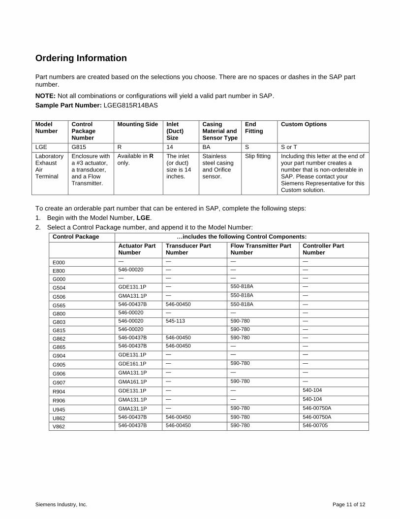
Siemens Industry, Inc. Page 11 of 12
Ordering Information
Part numbers are created based on the selections you choose. There are no spaces or dashes in the SAP part number.
NOTE: Not all combinations or configurations will yield a valid part number in SAP. Sample Part Number: LGEG815R14BAS Model Number
Control Package Number
Mounting Side Inlet (Duct) Size
Casing Material and Sensor Type
End Fitting
Custom Options
LGE G815 R 14 BA S S or T Laboratory Exhaust Air Terminal
Enclosure with a #3 actuator, a transducer, and a Flow Transmitter.
Available in R only.
The inlet (or duct) size is 14 inches.
Stainless steel casing and Orifice sensor.
Slip fitting Including this letter at the end of your part number creates a number that is non-orderable in SAP. Please contact your Siemens Representative for this Custom solution.
To create an orderable part number that can be entered in SAP, complete the following steps: 1. Begin with the Model Number, LGE. 2. Select a Control Package number, and append it to the Model Number:
Control Package …includes the following Control Components:
Actuator Part Number
Transducer Part Number
Flow Transmitter Part Number
Controller Part Number
E000 — — — —
E800 546-00020 — — —
G000 — — — —
G504 GDE131.1P — 550-818A —
G506 GMA131.1P — 550-818A —
G565 546-00437B 546-00450 550-818A —
G800 546-00020 — — —
G803 546-00020 545-113 590-780 —
G815 546-00020 590-780 —
G862 546-00437B 546-00450 590-780 —
G865 546-00437B 546-00450 — —
G904 GDE131.1P — — —
G905 GDE161.1P — 590-780 —
G906 GMA131.1P — — —
G907 GMA161.1P — 590-780 —
R904 GDE131.1P — — 540-104
R906 GMA131.1P — — 540-104
U945 GMA131.1P — 590-780 546-00750A
U862 546-00437B 546-00450 590-780 546-00750A
V862 546-00437B 546-00450 590-780 546-00705

Information in this document is based on specifications believed correct at the time of publication. The right is reserved to make changes as design improvements are introduced. APOGEE is a registered trademark of Siemens Industry, Inc. Other product or company names mentioned herein may be the trademarks of their respective owners. © 2011 Siemens Industry, Inc.
Siemens Industry, Inc. Building Technologies Division 1000 Deerfield Parkway Buffalo Grove, IL 60089-4513 USA + 1 847-215-1000
Your feedback is important to us. If you have comments about this document, please send them to [email protected] .
Document No. 149-320P25 Printed in the USA
Page 12 of 12
Control Components Legend
Part Number Description Part Number Description
540-104 Constant Volume TEC with Auto-Zero Module 546-00750A Constant volume Fume Hood Controller
545-113 AOP 0-10V - Voltage to Pneumatic Transducer, 0-10 Vdc input
550-818A OAM - Offboard Air Module
546-00020 No. 3 Pneumatic Actuator 590-780 Differential Pressure Transmitter, 1‖ WC, 4-20 mA, 0.4% accuracy
546-00090 High-Speed Pulsed Pneumatic Transducer GDE131.1P Fail-in-Last Position, Floating, 44 in-lb electric actuator
546-00437B L.E.A - Lab Electronic Actuator GDE161.1P Fail-in-Last Position, Modulation, 44 in-lb electric actuator
546-00450 Interface Board for L.E.A. ―AN‖= 10 Vdc, ―FP‖= Floating GMA131.1P Fail-safe Spring Return Floating, 62 in-
lb electric actuator 546-00705 Variable Volume Fume Hood Controller GMA161.1P Fail-safe Spring Return Modulating 62
in-lb electric actuator
3. Choose R for the Mounting Side, and append the letter to the part number. (The R is required.) 4. Choose the Inlet size (the size of the duct), and append the 2-digit number to the part number.
Inlet Size
(in inches) 2-digit Number Inlet Size
(in inches) 2-digit number
4 04 11 11 (12‖ casing with special orifice) 6 06 12 12 7 07 14 14 8 08 16 16 9 09 18 18 10 10 — —
5. Choose the Casing Material and the Sensor, and append the letters to the part number:
Casing Material and Sensor Type
AA Galvanized steel casing with orifice sensor. AB Galvanized steel casing with multi-point sensor. (Does not apply to inlet sizes 4, 11, or 18.) BA Stainless steel casing with orifice sensor. CA Teflon®-coated steel casing with orifice sensor.
6. Select the End fitting, and append that letter to the part number:
S = Slip
F = Flange
7. (Custom Options) This selection is for custom orders only, and will not be accepted in SAP. Please see your Siemens representative if you want to choose one or both of these options: T = Transformer (120/24 CL.2) and Disconnect Switch
S = Volara Blade Seals
After completing your selections, you should have an SAP orderable part number that looks similar to the example given here: SAMPLE Part Number: LGEG815R14BAS

SPECIFICATION SECTIONS TO BE INCLUDED IN FINAL SUBMITTAL
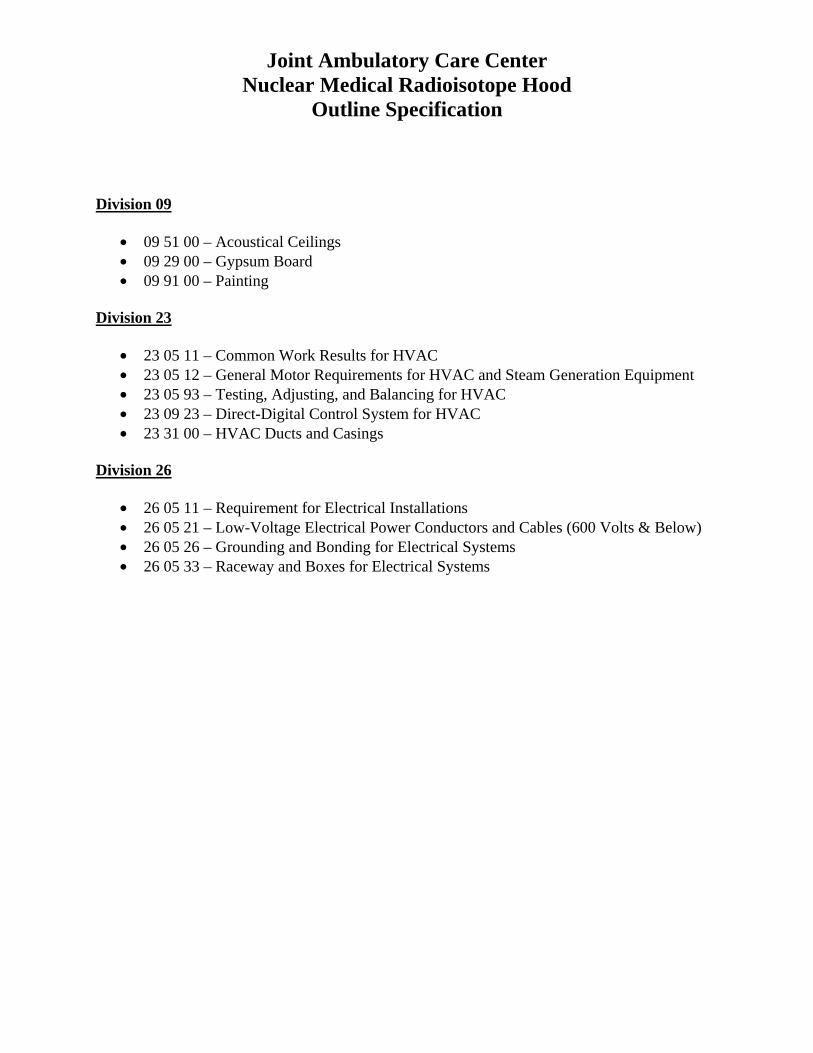
Joint Ambulatory Care Center Nuclear Medical Radioisotope Hood
Outline Specification Division 09
• 09 51 00 – Acoustical Ceilings • 09 29 00 – Gypsum Board • 09 91 00 – Painting
Division 23
• 23 05 11 – Common Work Results for HVAC • 23 05 12 – General Motor Requirements for HVAC and Steam Generation Equipment • 23 05 93 – Testing, Adjusting, and Balancing for HVAC • 23 09 23 – Direct-Digital Control System for HVAC • 23 31 00 – HVAC Ducts and Casings
Division 26
• 26 05 11 – Requirement for Electrical Installations • 26 05 21 – Low-Voltage Electrical Power Conductors and Cables (600 Volts & Below) • 26 05 26 – Grounding and Bonding for Electrical Systems • 26 05 33 – Raceway and Boxes for Electrical Systems

NUCLEAR MEDICAL RADIOSOTOPE HOOD (JACC)
SPECIFICATIONS May 10, 2013
VA Gulf Coast Veterans Health Care System Joint Ambulatory Care Center (JACC)
790 Veterans Way Pensacola, FL 39507
By JMZ Group
200 East Government St. Pensacola, FL 32502
(850) 433-3023 With:
Kariher Daughtry Architects PL (850) 433-3023
H.M. Yonge and Associates (850) 434 2661
Bagwell Yates and Associates (850) 462 8040
Nuclear Medical Radioisotope Hood (JACC)
Joint Ambulatory Care Center
Table of Contents
SECTION 1 GENERAL REQUIREMENTS
00 01 15 List of Drawing Sheets 01 00 00 General Requirements 01 33 23 Shop Drawings, Product Data, and Samples
SECTION 7 THERMAL AND MOISTURE PROTECTON
07 84 00 Firestopping
SECTION 9 FINISHES
09 29 00 Gypsum Wall Board 09 51 00 Acoustical Ceilings 09 91 00 Painting
SECTION 23 HEATING VENTILATION AND AIR CONDITIONING
23 05 11 Common Work Results for HVAC 23 05 12 General Motor Requirements for HVAC and Steam Generation Equipment 23 05 93 Testing, Adjusting, and Balancing for HVAC 23 09 23 Direct Digital Control Systems for HVAC 23 31 00 HVAC Ducts and Casings
SECTION 26 ELECTRICAL
26 05 11 Requirements for Electrical Installations 26 05 21 Low-Voltage Electrical Power Conductors & Cables (600 Volts & Below) 26 05 26 Grounding and Bonding for Electrical Systems 26 05 33 Raceway and Boxes for Electrical Systems
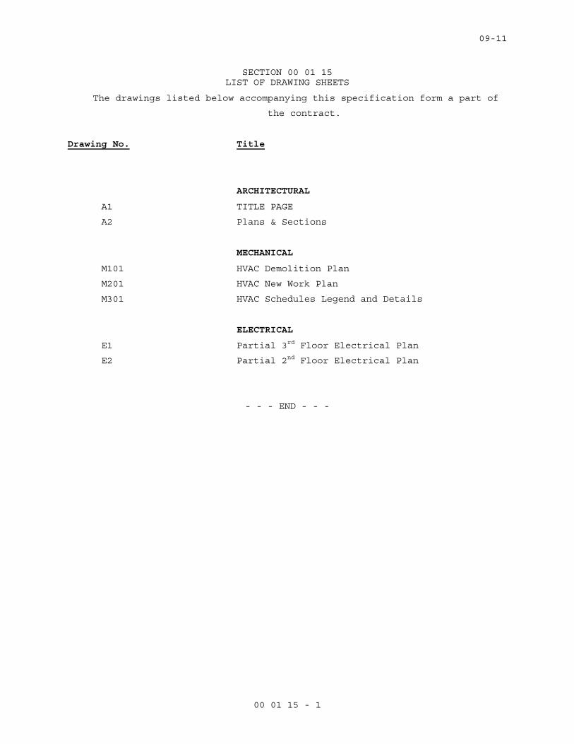
09-11
00 01 15 - 1
SECTION 00 01 15 LIST OF DRAWING SHEETS
The drawings listed below accompanying this specification form a part of
the contract.
Drawing No. Title
ARCHITECTURAL
A1 TITLE PAGE
A2 Plans & Sections
MECHANICAL
M101 HVAC Demolition Plan
M201 HVAC New Work Plan
M301 HVAC Schedules Legend and Details
ELECTRICAL
E1 Partial 3rd Floor Electrical Plan
E2 Partial 2nd Floor Electrical Plan
- - - END - - -

12-07M
01 00 00 -1
SECTION 01 00 00 GENERAL REQUIREMENTS
TABLE OF CONTENTS
1.1 GENERAL INTENTION…………………….………………………..……………………1
1.2 STATEMENT OF BID ITEM(S)……………………………………………….…………….1
1.3 SPECIFICATIONS AND DRAWINGS FOR CONTRACTOR……………………………...1
1.4 CONSTRUCTION SECURITY REQUIREMENTS………………………………………....1
1.5 FIRE SAFETY…………………...……………………………………………………………3
1.6 OPERATIONS AND STORAGE AREAS……………………………………………………4
1.7 ALTERATIONS…………………………………………………………………………..…..8
1.8 INFECTION PREVENTION MEASURES…………………………………………………..9
1.9 DISPOSAL AND RETENTION…………………………………………………...…………9
1.10 PROTECTION OF EXISTING VEGETATION, STRUCTURES, EQUIPMENT, UTILITIES, AND IMPROVEMENT ………………………...…………………………………9
1.11 RESTORATION……………………………………………………………………………..9
1.12 PHYSICAL DATA ……………………………………………………………………...…10
1.13 LAYOUT OF WORK…………………………………………………………………..…..10
1.14 AS-BUILT DRAWINGS…………………………………………………………….……..12
1.15 USE OF ROADWAYS……………………………………………………………….…….12
1.16 TEMPORARY TOILETS………………………………………………...………………..12
1.17 AVAILABILITY AND USE OF UTILITY SERVICES……………………..…………...12
1.18 TESTS………………………………………………………………………..……………13
1.19 INSTRUCTIONS…………………………………………………………..……..…….....14
SECTION 01 00 00 GENERAL REQUIREMENTS

12-07M
01 00 00 -2
1.1 GENERAL INTENTION
A. Contractor shall completely prepare site for operations, including demolition and removal of
existing structures, and furnish labor and materials and perform work for Project VA-256-11-RP-
0207 “Install Nuclear Medical Radioisotope Hood, VA Gulf Coast Veterans Health Care System,
Joint Ambulatory Care Center (JACC), 790 Veterans Way, Pensacola, FL” as required by
drawings and specifications.
B. Visits to the site by Bidders may be made only by appointment with the COTR.
C. All employees of general contractor and subcontractors shall comply with Navy and VA security
management program and obtain permission of the Navy police, be identified by project and
employer, and restricted from unauthorized access.
D. Prior to commencing work, general contractor shall provide proof that a OSHA certified
“competent person” (CP) (29 CFR 1926.20(b)(2) will maintain a presence at the work site
whenever the general or subcontractors are present.
E. Training:
1. All employees of general contractor or subcontractors shall have the 10-hour OSHA certified
Construction Safety course and /or other relevant competency training, as determined by
VA CP with input from the ICRA team.
2. Submit training records of all such employees for approval before the start of work.
1.2 STATEMENT OF BID ITEM(S)
A.ITEM I, GENERAL CONSTRUCTION: Refer to Scope of Work.
1.3 SPECIFICATIONS AND DRAWINGS FOR CONTRACTOR
A. AFTER AWARD OF CONTRACT, __4___ sets of specifications and drawings will be furnished.
B. Additional sets of drawings may be made by the Contractor, at Contractor's expense, from
reproducible sepia prints furnished by Issuing Office. Such sepia prints shall be returned to the
Issuing Office immediately after printing is completed.
1.4 CONSTRUCTION SECURITY REQUIREMENTS
A. Security Procedures:

12-07M
01 00 00 -3
1. General Contractor’s employees shall not enter the base project site without appropriate
badge. They may also be subject to inspection of their personal effects when entering or
leaving the project site.
2. For working outside the “regular hours” as defined in the contract, The General Contractor
shall give 3 days notice to the Contracting Officer so that security/escort arrangements and
extended base access can be provided. This notice is separate from any notices required for
utility shutdown described later in this section.
3. No photography of VA or base premises is allowed without written permission of the
Contracting Officer.
4. VA reserves the right to close down or shut down the project site and order General
Contractor’s employees off the premises in the event of a national emergency. The General
Contractor may return to the site only with the written approval of the Contracting Officer.
B. Document Control:
1. The General Contractor is responsible for safekeeping of all drawings, project manual and
other project information. This information shall be shared only with those with a specific
need to accomplish the project.
2. Certain documents, sketches, videos or photographs and drawings may be marked “Law
Enforcement Sensitive” or “Sensitive Unclassified”. Secure such information in separate
containers and limit the access to only those who will need it for the project. Return the
information to the Contracting Officer upon request.
3. These security documents shall not be removed or transmitted from the project site without
the written approval of Contracting Officer.
4. All paper waste or electronic media such as CD’s and diskettes shall be shredded and
destroyed in a manner acceptable to the VA.
5. Notify Contracting Officer and Site Security Officer immediately when there is a loss or
compromise of “sensitive information”.
12-07M
01 00 00 -4
6. All electronic information shall be stored in specified location following VA standards and
procedures using an Engineering Document Management Software (EDMS).
a. Security, access and maintenance of all project drawings, both scanned and electronic
shall be performed and tracked through the EDMS system.
b. “Sensitive information” including drawings and other documents may be attached to e-
mail provided all VA encryption procedures are followed.
C. Motor Vehicle Restrictions: IAW VA requirements; as a minimum, proper state drivers license,
proof of insurance, and proof of vehicle registration required to operate motor vehicle on VA
premises.
1.5 FIRE SAFETY
A. Applicable Publications: Publications listed below form part of this Article to extent referenced.
Publications are referenced in text by basic designations only.
1. American Society for Testing and Materials (ASTM):
E84-2007 .............................. Surface Burning Characteristics of Building Materials
2. National Fire Protection Association (NFPA):
10-2006................................ Standard for Portable Fire Extinguishers
30-2003................................ Flammable and Combustible Liquids Code
51B-2003 ............................. Standard for Fire Prevention During Welding, Cutting and Other
Hot Work
70-2005................................ National Electrical Code
241-2004 ............................. Standard for Safeguarding Construction, Alteration, and
Demolition Operations
3. Occupational Safety and Health Administration (OSHA):
29 CFR 1926 ......................... Safety and Health Regulations for Construction
12-07M
01 00 00 -5
B. Site and Building Access: Maintain free and unobstructed access to facility emergency services
and for fire, police and other emergency response forces in accordance with NFPA 241.
C. Egress Routes: Maintain free and unobstructed egress. Inspect daily.
D. Fire Extinguishers: Provide and maintain extinguishers in construction areas and temporary
storage areas in accordance with 29 CFR 1926, NFPA 241 and NFPA 10.
E. Flammable and Combustible Liquids: Store, dispense and use liquids in accordance with 29 CFR
1926, NFPA 241 and NFPA 30.
F. Existing Fire Protection: Do not impair any fire protection systems in the accomplishment of
work. Provide fire watch for impairments more than 4 hours in a 24-hour period. Request
interruptions in accordance with Article, OPERATIONS AND STORAGE AREAS, and coordinate
with COTR and base facility Safety Officer.
G. Hot Work: Perform and safeguard hot work operations in accordance with NFPA 241 and NFPA
51B. Coordinate with COTR. Obtain permits from facility Safety Officer at least __72__ hours in
advance.
H. Fire Hazard Prevention and Safety Inspections: Inspect entire construction areas weekly.
Coordinate with, and report findings and corrective actions on construction progress reports
(aka “daily logs”), which are part of the construction contract record documents.
I. Smoking: Smoking is prohibited in and adjacent to construction areas inside existing buildings
and additions under construction. Comply with all base smoking restrictions.
J. Dispose of waste and debris in accordance with NFPA 241. Remove from buildings/site daily.
K. Perform other construction, alteration and demolition operations in accordance with 29 CFR
1926.
1.6 OPERATIONS AND STORAGE AREAS
A. The Contractor shall confine all operations (including storage of materials) on Government
premises to areas authorized or approved by the Contracting Officer. The Contractor shall hold
and save the Government, its officers and agents, free and harmless from liability of any nature
occasioned by the Contractor's performance.
12-07M
01 00 00 -6
B. Temporary buildings (e.g., storage sheds, shops, offices) and utilities may be erected by the
Contractor only with the approval of the Contracting Officer and shall be built with labor and
materials furnished by the Contractor without expense to the Government. The temporary
buildings and utilities shall remain the property of the Contractor and shall be removed by the
Contractor at its expense upon completion of the work. With the written consent of the
Contracting Officer, the buildings and utilities may be abandoned and need not be removed.
C. The Contractor shall, under regulations prescribed by the Contracting Officer, use only
established roadways as authorized by the Contracting Officer. When materials are transported
in prosecuting the work, vehicles shall not be loaded beyond the loading capacity recommended
by the manufacturer of the vehicle or prescribed by any Federal, State, or local law or regulation.
When it is necessary to cross curbs or sidewalks, the Contractor shall protect them from
damage. The Contractor shall repair or pay for the repair of any damaged curbs, sidewalks, or
roads.
D. Working space and space available for storing materials shall be as determined by the COTR and
base.
E. Workmen are subject to rules of VA applicable to their conduct.
F. Execute work so as to interfere as little as possible with normal functioning of Base as a whole,
including operations of utility services, fire protection systems and any existing equipment, and
with work being done by others. Use of equipment and tools that transmit vibrations and noises
through the building structure, are not permitted in buildings that are occupied, during
construction, jointly by government personnel, and Contractor's personnel, except as permitted
by COTR where required by limited working space.
1. Do not store materials and equipment in other than assigned areas.
2. Schedule delivery of materials and equipment to immediate construction working areas
outside or within buildings in use by Government in quantities sufficient for not more than
two work days. Provide unobstructed access to base areas required to remain in operation.
G. Utilities Services Impact: Where necessary to cut existing pipes, electrical wires, conduits, cables,
etc., of utility services, or of fire protection systems or communications systems (except
telephone), they shall be cut and capped at suitable places where shown; or, in absence of such
12-07M
01 00 00 -7
indication, where directed by COTR. All such actions shall be coordinated with the Utility
Company involved:
1. Whenever it is required that a connection fee be paid to a public utility provider for new
permanent service to the construction project, for such items as water, sewer, electricity,
gas or steam, payment of such fee shall be the responsibility of the Government and not the
Contractor.
H. Phasing: To insure such executions, Contractor shall furnish the COTR with a schedule of
approximate phasing dates on which the Contractor intends to accomplish work in each specific
area of site, building or portion thereof. In addition, Contractor shall notify the COTR two weeks
in advance of the proposed date of starting work in each specific area of site, building or portion
thereof. Arrange such phasing dates to insure accomplishment of this work in successive phases
mutually agreeable to COTR, CO, and Contractor.
I. Contractor will be allowed space on VA grounds to park temporary storage trailers. Coordinate
with VA Resident Engineer. Construction Fence if required to secure materials: Before
construction operations begin, Contractor shall provide a chain link construction fence, 2100
mm (seven feet) minimum height, around the construction storage area. Provide gates as
required for access with necessary hardware, including hasps and padlocks. Fasten fence fabric
to terminal posts with tension bands and to line posts and top and bottom rails with tie wires
spaced at maximum 15 inches. Bottom of fences shall extend to one inch above grade. Remove
the fence when directed by COTR.
J. Utilities Services: Maintain existing utility services for base at all times. Provide temporary
facilities, labor, materials, equipment, connections, and utilities to assure uninterrupted
services. Where necessary to cut existing water, steam, gases, sewer or air pipes, or conduits,
wires, cables, etc. of utility services or of fire protection systems and communications systems
(including telephone), they shall be cut and capped at suitable places where shown; or, in
absence of such indication, where directed by COTR.
1. No utility service such as water, gas, steam, sewers or electricity, or fire protection systems
and communications systems may be interrupted without prior approval of COTR. Electrical
work shall be accomplished with all affected circuits or equipment de-energized. When an
12-07M
01 00 00 -8
electrical outage cannot be accomplished, work on any energized circuits or equipment shall
not commence without the Medical Center Director’s prior knowledge and written approval.
2. Contractor shall submit a request to interrupt any such services to COTR, in writing, 48 hours
in advance of proposed interruption. Request shall state reason, date, exact time of, and
approximate duration of such interruption.
3. Contractor will be advised (in writing) of approval of request, or of which other date and/or
time such interruption will cause least inconvenience to operations of base. Interruption
time approved by COTR may occur at other than Contractor's normal working hours.
4. Major interruptions of any system must be requested, in writing, at least 15 calendar days
prior to the desired time and shall be performed as directed by the COTR.
5. In case of a contract construction emergency, service will be interrupted on approval of
COTR. Such approval will be confirmed in writing as soon as practical.
6. Whenever it is required that a connection fee be paid to a public utility provider for new
permanent service to the construction project, for such items as water, sewer, electricity,
gas or steam, payment of such fee shall be the responsibility of the Government and not the
Contractor.
K. Abandoned Lines: All service lines such as wires, cables, conduits, ducts, pipes and the like, and
their hangers or supports, which are to be abandoned but are not required to be entirely
removed, shall be sealed, capped or plugged. The lines shall not be capped in finished areas, but
shall be removed and sealed, capped or plugged in ceilings, within furred spaces, in unfinished
areas, or within walls or partitions; so that they are completely behind the finished surfaces.
L. To minimize interference of construction activities with flow of base traffic, comply with the
following:
1. Keep roads, walks and entrances to grounds, to parking and to occupied areas of buildings
clear of construction materials, debris and standing construction equipment and vehicles.
Wherever excavation for new utility lines cross or bore beneath existing roads, at least one
lane must be open to traffic at all times.

12-07M
01 00 00 -9
2. Method and scheduling of required cutting, altering and removal of existing roads, walks
and entrances must be approved by the COTR.
M. Coordinate the work for this contract with other construction operations as directed by COTR.
This includes the scheduling of traffic and the use of roadways, as specified in Article, USE OF
ROADWAYS.
1.7 ALTERATIONS
A. Survey: Before any work is started, the Contractor shall make a thorough survey with the COTR,
and a base rep, of areas and within/outside of buildings in which alterations occur and areas
which are anticipated routes of access, and furnish a report, signed by all three, to the
Contracting Officer. This report shall list:
1. Existing conditions found of areas not required to be altered.
2. Shall note any discrepancies between drawings and existing conditions at site.
3. Shall designate areas for working space, materials storage and routes of access to areas
within buildings where alterations occur and which have been agreed upon by Contractor
and COTR.
B. Re-Survey: Fourteen days before expected partial or final inspection date, the Contractor and
Resident Engineer together shall make a thorough re-survey of the areas of buildings involved.
They shall furnish a report on conditions then existing, of resilient flooring, doors, windows,
walls and other surfaces as compared with conditions of same as noted in first condition survey
report:
1. Re-survey report shall also list any damage caused by Contractor to such flooring and other
surfaces, despite protection measures; and, will form basis for determining extent of repair
work required of Contractor to restore damage caused by Contractor's workmen in
executing work of this contract.
C. Protection: Provide the following protective measures:
1. Wherever existing roof surfaces are disturbed they shall be protected against water
infiltration. In case of leaks, they shall be repaired immediately upon discovery.

12-07M
01 00 00 -10
2. Temporary protection against damage for portions of existing structures and grounds where
work is to be done, materials handled and equipment moved and/or relocated.
3. Protection of interior of existing structures at all times, from damage, dust and weather
inclemency. Wherever work is performed, floor surfaces shall be adequately protected prior
to starting work, and this protection shall be maintained intact until all work in the area is
completed.
1.8 INFECTION PREVENTION MEASURES
A. Establish and maintain a dust control program as part of the contractor’s infection
preventive measures.
1.9 DISPOSAL AND RETENTION
A. Materials and equipment accruing from work removed and from demolition or parts thereof,
shall be disposed of as follows:
1. Items not reserved shall become property of the Contractor and be removed by Contractor
from base property.
1.10 PROTECTION OF EXISTING VEGETATION, STRUCTURES, EQUIPMENT, UTILITIES, AND IMPROVEMENTS
A. The Contractor shall preserve and protect all structures, equipment, and vegetation (such as
trees, shrubs, and grass) on or adjacent to the work site, which are not to be removed and which
do not unreasonably interfere with the work required under this contract. If any limbs or
branches of trees are broken during contract performance, or by the careless operation of
equipment, or by workmen, the Contractor shall trim those limbs or branches with a clean cut
and paint the cut with a tree-pruning compound as directed by the Contracting Officer.
B. The Contractor shall protect from damage all existing improvements and utilities at or near the
work site and on adjacent property of a third party, the locations of which are made known to or
should be known by the Contractor. The Contractor shall repair any damage to those facilities,
including those that are the property of a third party, resulting from failure to comply with the
requirements of this contract or failure to exercise reasonable care in performing the work. If
the Contractor fails or refuses to repair the damage promptly, the Contracting Officer may have
the necessary work performed and charge the cost to the Contractor.

12-07M
01 00 00 -11
1.11 RESTORATION
A. Remove, cut, alter, replace, patch and repair existing work as necessary to install new work.
Except as otherwise shown or specified, do not cut, alter or remove any structural work, and do
not disturb any ducts, plumbing, steam, gas, or electric work without approval of the COTR.
Existing work to be altered or extended and that is found to be defective in any way, shall be
reported to the COTR before it is disturbed. Materials and workmanship used in restoring work,
shall conform in type and quality to that of original existing construction, except as otherwise
shown or specified.
B. Upon completion of contract, deliver work complete and undamaged. Existing work (walls,
ceilings, partitions, floors, mechanical and electrical work, lawns, paving, roads, walks, etc.)
disturbed or removed as a result of performing required new work, shall be patched, repaired,
reinstalled, or replaced with new work, and refinished and left in as good condition as existed
before commencing work.
C. At Contractor's own expense, Contractor shall immediately restore to service and repair any
damage caused by Contractor's workmen to existing piping and conduits, wires, cables, etc., of
utility services or of fire protection systems and communications systems (including telephone)
which are indicated on drawings and which are not scheduled for discontinuance or
abandonment.
D. Expense of repairs to such utilities and systems not shown on drawings or locations of which are
unknown will be covered by adjustment to contract time and price in accordance with clause
entitled "CHANGES" (FAR 52.243-4 and VAAR 852.236-88) and "DIFFERING SITE CONDITIONS"
(FAR 52.236-2) of Section 00 72 00, GENERAL CONDITIONS.
1.12 PHYSICAL DATA
A. If required for trenching and under-road boring operations, Bidders are expected to examine site
of work and logs of borings; and, after investigation, decide for themselves character of
materials and make their bids accordingly. Upon proper application to Department of Veterans
Affairs, bidders will be permitted to make subsurface explorations of their own at site.
12-07M
01 00 00 -12
1.13 LAYOUT OF WORK
A. The Contractor shall lay out the work and shall be responsible for all measurements in
connection with the layout. The Contractor shall furnish, at Contractor's own expense, all
stakes, templates, platforms, equipment, tools, materials, and labor required to lay out any part
of the work. The Contractor shall be responsible for executing the work to the lines and grades
that may be established or indicated. The Contractor shall also be responsible for maintaining
and preserving all stakes and other marks established by the Government until authorized to
remove them. If such marks are destroyed by the Contractor or through Contractor's negligence
before their removal is authorized, the Contracting Officer may replace them and deduct the
expense of the replacement from any amounts due or to become due to the Contractor.
(FAR 52.236-17)
1.14 AS-BUILT DRAWINGS
A. The contractor shall maintain two full size sets of as-built drawings which will be kept current
during construction of the project, to include all contract changes, modifications and
clarifications.
B. All variations shall be shown in the same general detail as used in the contract drawings. To
insure compliance, as-built drawings shall be made available for the COTR’s review, as often as
requested.
C. Contractor shall deliver two approved completed sets of as-built drawings to the COTR within 15
calendar days after each completed phase and after the acceptance of the project by the COTR.
D. Paragraphs A, B, & C shall also apply to all shop drawings.
1.15 USE OF ROADWAYS
A. For hauling, use only established public roads and roads on Medical Center property and, when
authorized by the COTR.
1.16 TEMPORARY TOILETS
A. Contractor may have for use of Contractor's workmen, such toilet accommodations as may be
assigned to Contractor by COTR. Contractor shall keep such places clean and be responsible for

12-07M
01 00 00 -13
any damage done thereto by Contractor's workmen. Failure to maintain satisfactory condition in
toilets will deprive Contractor of the privilege to use such toilets.
1.17 AVAILABILITY AND USE OF UTILITY SERVICES
A. The Government shall make all reasonably required amounts of utilities available to the
Contractor from existing outlets and supplies. The amount to be paid by the Contractor for
chargeable electrical services shall be the prevailing rates charged to the Government. The
Contractor shall carefully conserve any utilities furnished without charge.
B. The Contractor, at Contractor's expense and in a workmanlike manner satisfactory to the
Contracting Officer, shall install and maintain all necessary temporary connections and
distribution lines, and all meters required to measure the amount of electricity used for the
purpose of determining charges. Before final acceptance of the work by the Government, the
Contractor shall remove all the temporary connections, distribution lines, meters, and
associated paraphernalia.
C. Electricity (for Construction and Testing and Storage Trailers): Furnish all temporary electric
services.
1. Obtain electricity by connecting to the VA electrical distribution system. The Contractor shall
meter and pay for electricity required for electric cranes and hoisting devices, electrical
welding devices and any electrical heating devices providing temporary heat. Electricity for
all other uses is available at no cost to the Contractor.
D. Water (for Construction and Testing):
1. Obtain water by connecting to the Medical Center water distribution system. Provide
reduced pressure backflow preventer at each connection. Water is available at no cost to
the Contractor.
2. Maintain connections, pipe, fittings and fixtures and conserve water-use so none is wasted.
Failure to stop leakage or other wastes will be cause for revocation (at COTR’s discretion) of
use of water from base system.

12-07M
01 00 00 -14
1.18 TESTS
A. Pre-test systems and make corrections required for proper operation of such systems before
requesting final tests. Final test will not be conducted unless pre-tested.
B. Conduct final tests required in various sections of specifications in presence of an authorized
representative of the Contracting Officer. Contractor shall furnish all labor, materials,
equipment, instruments, and forms, to conduct and record such tests.
C. Systems shall be balanced, controlled and coordinated. A system is defined as the entire
complex which must be coordinated to work together during normal operation to produce
results for which the system is designed.
D. All related components as defined above shall be functioning when any system component is
tested. Tests shall be completed within a reasonably short period of time during which operating
and environmental conditions remain reasonably constant.
E. Individual test result of any component, where required, will only be accepted when submitted
with the test results of related components and of the entire system.
1.19 INSTRUCTIONS
A. Contractor shall furnish Maintenance and Operating manuals and verbal instructions when
required by the various sections of the specifications and as hereinafter specified.
B. Manuals: Maintenance and operating manuals (four copies each) for each separate piece of
material or equipment shall be delivered to the COTR coincidental with the delivery to the job
site. Manuals shall be complete, detailed guides for the maintenance and operation. They shall
include complete information necessary for maintaining in continuous operation for long
periods of time and dismantling and reassembling of the complete units and sub-assembly
components. Manuals shall include an index covering all component parts clearly
cross-referenced to diagrams and illustrations. Illustrations shall include "exploded" views
showing and identifying each separate item. Emphasis shall be placed on the use of special tools
and instruments. The function of each piece of equipment, component, accessory and control
shall be clearly and thoroughly explained. All necessary precautions for the operation of the
equipment and the reason for each precaution shall be clearly set forth. Manuals must reference
the exact model, style and size of the piece of equipment and system being furnished. Manuals

12-07M
01 00 00 -15
referencing equipment similar to but of a different model, style, and size than that furnished will
not be accepted.
C. Instructions if required: Contractor shall provide qualified, factory-trained manufacturers'
representatives to give detailed instructions to assigned Navy and Department of Veterans
Affairs personnel in the operation and complete maintenance. All such training will be at the job
site. These requirements are more specifically detailed in the various technical sections.
Instructions for different items of equipment that are component parts of a complete system,
shall be given in an integrated, progressive manner. All instructors for every piece of component
equipment in a system shall be available until instructions for all items included in the system
have been completed. This is to assure proper instruction in the operation of inter-related
systems. All instruction periods shall be at such times as scheduled by the COTR and shall be
considered concluded only when the COTR is satisfied in regard to complete and thorough
coverage.
- - - E N D - - -
03-01-12
01 33 23 - 1
SECTION 01 33 23 SHOP DRAWINGS, PRODUCT DATA, AND SAMPLES
1-1. Refer to Articles titled SPECIFICATIONS AND DRAWINGS FOR CONSTRUCTION
(FAR 52.236-21) and, SPECIAL NOTES (VAAR 852.236-91), in GENERAL
CONDITIONS.
1-2. For the purposes of this contract, samples, test reports, certificates,
and manufacturers' literature and data shall also be subject to the
previously referenced requirements. The following text refers to all
items collectively as SUBMITTALS.
1-3. Submit for approval, all of the items specifically mentioned under the
separate sections of the specification, with information sufficient to
evidence full compliance with contract requirements. Materials,
fabricated articles and the like to be installed in permanent work shall
equal those of approved submittals. After an item has been approved, no
change in brand or make will be permitted unless:
A. Satisfactory written evidence is presented to, and approved by
Contracting Officer, that manufacturer cannot make scheduled delivery of
approved item or;
B. Item delivered has been rejected and substitution of a suitable item is
an urgent necessity or;
C. Other conditions become apparent which indicates approval of such
substitute item to be in best interest of the Government.
1-4. Forward submittals in sufficient time to permit proper consideration and
approval action by Government. Time submission to assure adequate lead
time for procurement of contract - required items. Delays attributable
to untimely and rejected submittals will not serve as a basis for
extending contract time for completion.
1-5. Submittals will be reviewed for compliance with contract requirements by
Architect-Engineer, and action thereon will be taken by Resident
Engineer on behalf of the Contracting Officer.
1-6. Upon receipt of submittals, Architect-Engineer will assign a file number
thereto. Contractor, in any subsequent correspondence, shall refer to
this file and identification number to expedite replies relative to
previously approved or disapproved submittals.
1-7. The Government reserves the right to require additional submittals,
whether or not particularly mentioned in this contract. If additional
submittals beyond those required by the contract are furnished pursuant
to request therefor by Contracting Officer, adjustment in contract price
and time will be made in accordance with Articles titled CHANGES (FAR
03-01-12
01 33 23 - 2
52.243-4) and CHANGES - SUPPLEMENT (VAAR 852.236-88) of the GENERAL
CONDITIONS.
1-8. Schedules called for in specifications and shown on shop drawings shall
be submitted for use and information of Department of Veterans Affairs
and Architect-Engineer. However, the Contractor shall assume
responsibility for coordinating and verifying schedules. The Contracting
Officer and Architect- Engineer assumes no responsibility for checking
schedules or layout drawings for exact sizes, exact numbers and detailed
positioning of items.
1-9. Submittals must be submitted by Contractor only and shipped prepaid.
Contracting Officer assumes no responsibility for checking quantities or
exact numbers included in such submittals.
A. Submit color samples required in quadruplicate. Submit other samples in
single units unless otherwise specified. Submit shop drawings,
schedules, manufacturers' literature and data, and certificates in
quadruplicate, except where a greater number is specified.
B. Submittals will receive consideration only when covered by a transmittal
letter signed by Contractor. Letter shall be sent via first class mail
and shall contain the list of items, name of Medical Center, name of
Contractor, contract number, applicable specification paragraph numbers,
applicable drawing numbers (and other information required for exact
identification of location for each item), manufacturer and brand, ASTM
or Federal Specification Number (if any) and such additional information
as may be required by specifications for particular item being
furnished. In addition, catalogs shall be marked to indicate specific
items submitted for approval.
1. A copy of letter must be enclosed with items, and any items received
without identification letter will be considered "unclaimed goods"
and held for a limited time only.
2. Each sample, certificate, manufacturers' literature and data shall be
labeled to indicate the name and location of the Medical Center,
name of Contractor, manufacturer, brand, contract number and ASTM or
Federal Specification Number as applicable and location(s) on
project.
3. Required certificates shall be signed by an authorized representative
of manufacturer or supplier of material, and by Contractor.
C. In addition to complying with the applicable requirements specified in
preceding Article 1.9, samples which are required to have Laboratory
Tests (those preceded by symbol "LT" under the separate sections of the

03-01-12
01 33 23 - 3
specification shall be tested, at the expense of Contractor, in a
commercial laboratory approved by Contracting Officer.
1. Laboratory shall furnish Contracting Officer with a certificate
stating that it is fully equipped and qualified to perform intended
work, is fully acquainted with specification requirements and
intended use of materials and is an independent establishment in no
way connected with organization of Contractor or with manufacturer or
supplier of materials to be tested.
2. Certificates shall also set forth a list of comparable projects upon
which laboratory has performed similar functions during past five
years.
3. Samples and laboratory tests shall be sent directly to approved
commercial testing laboratory.
4. Contractor shall send a copy of transmittal letter to both Resident
Engineer and to Architect-Engineer simultaneously with submission of
material to a commercial testing laboratory.
5. Laboratory test reports shall be sent directly to Resident Engineer
for appropriate action.
6. Laboratory reports shall list contract specification test
requirements and a comparative list of the laboratory test results.
When tests show that the material meets specification requirements,
the laboratory shall so certify on test report.
7. Laboratory test reports shall also include a recommendation for
approval or disapproval of tested item.
D. If submittal samples have been disapproved, resubmit new samples as soon
as possible after notification of disapproval. Such new samples shall be
marked "Resubmitted Sample" in addition to containing other previously
specified information required on label and in transmittal letter.
E. Approved samples will be kept on file by the Resident Engineer at the
site until completion of contract, at which time such samples will be
delivered to Contractor as Contractor's property. Where noted in
technical sections of specifications, approved samples in good condition
may be used in their proper locations in contract work. At completion of
contract, samples that are not approved will be returned to Contractor
only upon request and at Contractor's expense. Such request should be
made prior to completion of the contract. Disapproved samples that are
not requested for return by Contractor will be discarded after
completion of contract.
F. Submittal drawings (shop, erection or setting drawings) and schedules,
required for work of various trades, shall be checked before submission

03-01-12
01 33 23 - 4
by technically qualified employees of Contractor for accuracy,
completeness and compliance with contract requirements. These drawings
and schedules shall be stamped and signed by Contractor certifying to
such check.
1. For each drawing required, submit one legible photographic paper or
vellum reproducible.
2. Reproducible shall be full size.
3. Each drawing shall have marked thereon, proper descriptive title,
including Medical Center location, project number, manufacturer's
number, reference to contract drawing number, detail Section Number,
and Specification Section Number.
4. A space 4-3/4 by 5 inches) shall be reserved on each drawing to
accommodate approval or disapproval stamp.
5. Submit drawings, ROLLED WITHIN A MAILING TUBE, fully protected for
shipment.
6. One reproducible print of approved or disapproved shop drawings will
be forwarded to Contractor.
7. When work is directly related and involves more than one trade, shop
drawings shall be submitted to Architect-Engineer under one cover.
1-10. Samples, shop drawings, test reports, certificates and manufacturers'
literature and data, shall be submitted for approval to
________________________________________________________________
(Architect-Engineer)
________________________________________________________________
(A/E P.O. Address)
________________________________________________________________
(City, State and Zip Code)
1-11. At the time of transmittal to the Architect-Engineer, the Contractor
shall also send a copy of the complete submittal directly to the
Resident Engineer.
- - - E N D - - -
10-11
07 84 00 - 1
SECTION 07 84 00 FIRESTOPPING
PART 1 GENERAL
1.1 DESCRIPTION
A. Closures of openings in walls, floors, and roof decks against
penetration of flame, heat, and smoke or gases in fire resistant rated
construction.
B. Closure of openings in walls against penetration of gases or smoke in
smoke partitions.
1.2 RELATED WORK
A Fire and smoke damper assemblies in ductwork: Section 23 31 00, HVAC
DUCTS AND CASINGS.
1.3 SUBMITTALS
A. Submit in accordance with Section 01 33 23, SHOP DRAWINGS, PRODUCT
DATA, AND SAMPLES.
B. Manufacturers literature, data, and installation instructions for types
of firestopping and smoke stopping used.
C. List of FM, UL, or WH classification number of systems installed.
D. Certified laboratory test reports for ASTM E814 tests for systems not
listed by FM, UL, or WH proposed for use.
1.4 DELIVERY AND STORAGE
A. Deliver materials in their original unopened containers with
manufacturer’s name and product identification.
B. Store in a location providing protection from damage and exposure to
the elements.
1.5 WARRANTY
Firestopping work subject to the terms of the Article “Warranty of
Construction”, FAR clause 52.246-21, except extend the warranty period
to five years.
1.6 QUALITY ASSURANCE
FM, UL, or WH or other approved laboratory tested products will be
acceptable.
1.7 APPLICABLE PUBLICATIONS
A. Publications listed below form a part of this specification to the
extent referenced. Publications are referenced in the text by the basic
designation only.
B. American Society for Testing and Materials (ASTM):

10-11
07 84 00 - 2
E84-10..................Surface Burning Characteristics of Building
Materials
E814-11.................Fire Tests of Through-Penetration Fire Stops
C. Factory Mutual Engineering and Research Corporation (FM):
Annual Issue Approval Guide Building Materials
D. Underwriters Laboratories, Inc. (UL):
Annual Issue Building Materials Directory
Annual Issue Fire Resistance Directory
1479-10.................Fire Tests of Through-Penetration Firestops
E. Warnock Hersey (WH):
Annual Issue Certification Listings
PART 2 - PRODUCTS
2.1 FIRESTOP SYSTEMS
A. Use either factory built (Firestop Devices) or field erected (through-
Penetration Firestop Systems) to form a specific building system
maintaining required integrity of the fire barrier and stop the passage
of gases or smoke.
B. Through-penetration firestop systems and firestop devices tested in
accordance with ASTM E814 or UL 1479 using the "F" or "T" rating to
maintain the same rating and integrity as the fire barrier being
sealed. "T" ratings are not required for penetrations smaller than or
equal to 100 mm (4 in) nominal pipe or 0.01 m2 (16 sq. in.) in overall
cross sectional area.
C. Products requiring heat activation to seal an opening by its
intumescence shall exhibit a demonstrated ability to function as
designed to maintain the fire barrier.
D. Firestop sealants used for firestopping or smoke sealing shall have
following properties:
1. Contain no flammable or toxic solvents.
2. Have no dangerous or flammable out gassing during the drying or
curing of products.
3. Water-resistant after drying or curing and unaffected by high
humidity, condensation or transient water exposure.
4. When used in exposed areas, shall be capable of being sanded and
finished with similar surface treatments as used on the surrounding
wall or floor surface.
10-11
07 84 00 - 3
E. Firestopping system or devices used for penetrations by glass pipe,
plastic pipe or conduits, unenclosed cables, or other non-metallic
materials shall have following properties:
1. Classified for use with the particular type of penetrating material
used.
2. Penetrations containing loose electrical cables, computer data
cables, and communications cables protected using firestopping
systems that allow unrestricted cable changes without damage to the
seal.
3. Intumescent products which would expand to seal the opening and act
as fire, smoke, toxic fumes, and, water sealant.
F. Maximum flame spread of 25 and smoke development of 50 when tested in
accordance with ASTM E84.
G. FM, UL, or WH rated or tested by an approved laboratory in accordance
with ASTM E814.
H. Materials to be asbestos free.
2.2 SMOKE STOPPING IN SMOKE PARTITIONS
A. Use mineral fiber filler and bond breaker behind sealant.
B. Sealants shall have a maximum flame spread of 25 and smoke developed of
50 when tested in accordance with E84.
C. When used in exposed areas capable of being sanded and finished with
similar surface treatments as used on the surrounding wall or floor
surface.
PART 3 - EXECUTION
3.1 EXAMINATION
Submit product data and installation instructions, as required by
article, submittals, after an on site examination of areas to receive
firestopping.
3.2 PREPARATION
A. Remove dirt, grease, oil, loose materials, or other substances that
prevent adherence and bonding or application of the firestopping or
smoke stopping materials.
B. Remove insulation on insulated pipe for a distance of 150 mm (six
inches) on either side of the fire rated assembly prior to applying the
firestopping materials unless the firestopping materials are tested and
approved for use on insulated pipes.

10-11
07 84 00 - 4
3.3 INSTALLATION
A. Do not begin work until the specified material data and installation
instructions of the proposed firestopping systems have been submitted
and approved.
B. Install firestopping systems with smoke stopping in accordance with FM,
UL, WH, or other approved system details and installation instructions.
C. Install smoke stopping seals in smoke partitions.
3.4 CLEAN-UP AND ACCEPTANCE OF WORK
A. As work on each floor is completed, remove materials, litter, and
debris.
B. Do not move materials and equipment to the next-scheduled work area
until completed work is inspected and accepted by the Resident
Engineer.
C. Clean up spills of liquid type materials.
- - - E N D - - -
09 29 00 - 1
SECTION 09 29 00 GYPSUM BOARD
PART 1 - GENERAL
1.1 DESCRIPTION
This section specifies installation and finishing of gypsum board.
1.2 RELATED WORK
A. Lay in gypsum board ceiling panels: Section 09 51 00, ACOUSTICAL
CEILINGS.
1.3 TERMINOLOGY
A. Definitions and description of terms shall be in accordance with ASTM
C11, C840, and as specified.
B. Underside of Structure Overhead: In spaces where steel trusses or bar
joists are shown, the underside of structure overhead shall be the
underside of the floor or roof construction supported by the trusses or
bar joists.
C. "Yoked": Gypsum board cut out for opening with no joint at the opening
(along door jamb or above the door).
1.4 SUBMITTALS
A. Manufacturer's Literature and Data:
1. Cornerbead and edge trim.
2. Finishing materials.
3. Laminating adhesive.
4. Gypsum board, each type.
C. Shop Drawings:
1. Typical gypsum board installation, showing corner details, edge trim
details and the like.
2. Typical sound rated assembly, showing treatment at perimeter of
partitions and penetrations at gypsum board.
3. Typical shaft wall assembly.
4. Typical fire rated assembly and column fireproofing, indicating
details of construction same as that used in fire rating test.
D. Samples:
1. Cornerbead.
2. Edge trim.
3. Control joints.
E. Test Results:
1. Fire rating test, each fire rating required for each assembly.
2. Sound rating test.

09 29 00 - 2
1.5 DELIVERY, IDENTIFICATION, HANDLING AND STORAGE
In accordance with the requirements of ASTM C840.
1.6 ENVIRONMENTAL CONDITIONS
In accordance with the requirements of ASTM C840.
1.7 APPLICABLE PUBLICATIONS
A. The publications listed below form a part of this specification to the
extent referenced. The publications are referenced in the text by the
basic designation only.
B. American Society For Testing And Materials (ASTM):
C11-04..................Terminology Relating to Gypsum and Related
Building Materials and Systems
C475-02.................Joint Compound and Joint Tape for Finishing
Gypsum Board
C840-04.................Application and Finishing of Gypsum Board
C954-04.................Steel Drill Screws for the Application of Gypsum
Board or Metal Plaster Bases to Steel Stud from
0.033 in. (0.84mm) to 0.112 in. (2.84mm) in
thickness
C1002-04................Steel Self-Piercing Tapping Screws for the
Application of Gypsum Panel Products or Metal
Plaster Bases to Wood Studs or Steel Studs
C1047-04................Accessories for Gypsum Wallboard and Gypsum
Veneer Base
C1396-04................Gypsum Board
E84-04..................Surface Burning Characteristics of Building
Materials
E497-99.................Installing Sound Isolating Lightweight
Partitions
C. Underwriters Laboratories Inc. (UL):
Latest Edition..........Fire Resistance Directory
D. Inchcape Testing Services (ITS):
Latest Editions.........Certification Listings
PART 2 - PRODUCTS
2.1 GYPSUM BOARD
A. Gypsum Board: ASTM C1396, Type X, 16 mm (5/8 inch) thick unless shown
otherwise.
B. Coreboard or Shaft Wall Liner Panels.
1. ASTM C1396, Type X.

09 29 00 - 3
2. Coreboard for shaft walls 300, 400, 600 mm (12, 16, or 24 inches)
wide by required lengths 25 mm (one inch) thick with paper faces
treated to resist moisture.
C. Water Resistant Gypsum Backing Board: ASTM C620, Type X, 16 mm (5/8
inch) thick.
2.2 ACCESSORIES
A. ASTM C1047, except form of 0.39 mm (0.015 inch) thick zinc coated steel
sheet or rigid PVC plastic.
B. Flanges not less than 22 mm (7/8 inch) wide with punchouts or deformations as required to provide compound bond.
2.3 ACOUSTICAL (SOUND ATTENUATION) INSULATION:
A. Mineral Fiber Batt or Blankets: ASTM C665. Maximum flame spread of 25
and smoke development of 450 when tested in accordance with ASTM E84.
B. Thickness as shown; of widths and lengths to fit tight against framing.
2.4 FASTENERS
A. ASTM C1002 and ASTM C840, except as otherwise specified.
B. ASTM C954, for steel studs thicker than 0.04 mm (0.33 inch).
C. Select screws of size and type recommended by the manufacturer of the
material being fastened.
D. For fire rated construction, type and size same as used in fire rating
test.
E. Clips: Zinc-coated (galvanized) steel; gypsum board manufacturer's
standard items.
2.5 FINISHING MATERIALS AND LAMINATING ADHESIVE
ASTM C475 and ASTM C840.
PART 3 - EXECUTION
3.1 GYPSUM BOARD HEIGHTS
A. Extend all layers of gypsum board from floor to underside of structure
overhead on following partitions and furring:
1. Two sides of partitions:
a. Fire rated partitions.
b. Sound rated partitions.
c. Full height partitions shown (FHP).
2. One side of partitions or furring:
a. Inside of exterior wall furring or stud construction.
b. Room side of room without suspended ceilings.
c. Furring for pipes and duct shafts, except where fire rated shaft
wall construction is shown.

09 29 00 - 4
3. Extend all layers of gypsum board construction used for fireproofing
of columns from floor to underside of structure overhead, unless
shown otherwise.
B. In locations other than those specified, extend gypsum board from floor
to heights as follows:
1. Not less than 100 mm (4 inches) above suspended acoustical ceilings.
2. At ceiling of suspended gypsum board ceilings.
3.2 INSTALLING GYPSUM BOARD
A. Coordinate installation of gypsum board with other trades and related
work.
B. Install gypsum board in accordance with ASTM C840, except as otherwise
specified.
C. Use gypsum boards in maximum practical lengths to minimize number of end
joints.
D. Bring gypsum board into contact, but do not force into place.
E. Ceilings:
1. For single-ply construction, use perpendicular application.
2. For two-ply assembles:
a. Use perpendicular application.
b. Apply face ply of gypsum board so that joints of face ply do not
occur at joints of base ply with joints over framing members.
F. Walls (Except Shaft Walls):
1. When gypsum board is installed parallel to framing members, space
fasteners 300 mm (12 inches) on center in field of the board, and 200
mm (8 inches) on center along edges.
2. When gypsum board is installed perpendicular to framing members,
space fasteners 300 mm (12 inches) on center in field and along
edges.
3. Stagger screws on abutting edges or ends.
4. For single-ply construction, apply gypsum board with long dimension
either parallel or perpendicular to framing members as required to
minimize number of joints.
5. For two-ply gypsum board assemblies, apply base ply of gypsum board
to assure minimum number of joints in face layer. Apply face ply of
wallboard to base ply so that joints of face ply do not occur at
joints of base ply with joints over framing members.
6. For three-ply gypsum board assemblies, apply plies in same manner as
for two-ply assemblies, except that heads of fasteners need only be
driven flush with surface for first and second plies. Apply third ply
of wallboard in same manner as second ply of two-ply assembly, except

09 29 00 - 5
use fasteners of sufficient length enough to have the same
penetration into framing members as required for two-ply assemblies.
7. No offset in exposed face of walls and partitions will be permitted
because of single-ply and two-ply or three-ply application
requirements.
8. Installing Two Layer Assembly Over Sound Deadening Board:
a. Apply face layer of wallboard vertically with joints staggered
from joints in sound deadening board over framing members.
b. Fasten face layer with screw, of sufficient length to secure to
framing, spaced 300 mm (12 inches) on center around perimeter, and
400 mm (16 inches) on center in the field.
9. Control Joints ASTM C840 and as follows:
a. Locate at both side jambs of openings if gypsum board is not
"yoked". Use one system throughout.
b. Not required for wall lengths less than 9000 mm (30 feet).
c. Extend control joints the full height of the wall or length of
soffit/ceiling membrane.
G. Acoustical or Sound Rated Partitions, Fire Partitions:
1. Cut gypsum board for a space approximately 3 mm to 6 mm (1/8 to 1/4
inch) wide around partition perimeter.
2. Coordinate for application of caulking or sealants to space prior to
taping and finishing.
3. Follow ASTM E497 for sound rated partitions. STC minimum values as shown.
H. Accessories:
1. Set accessories plumb, level and true to line, neatly mitered at
corners and intersections, and securely attach to supporting surfaces
as specified.
2. Install in one piece, without the limits of the longest commercially
available lengths.
3. Corner Beads:
a. Install at all vertical and horizontal external corners and where
shown.
b. Use screws only. Do not use crimping tool.
4. Edge Trim (casings Beads):
a. At both sides of expansion and control joints unless shown
otherwise.
b. Where gypsum board terminates against dissimilar materials and at
perimeter of openings, except where covered by flanges, casings or
permanently built-in equipment.

09 29 00 - 6
c. Where gypsum board surfaces of non-load bearing assemblies abut
load bearing members.
d. Where shown. 3. Sound Attenuation (Acoustic) Insulation: Install full width of stud
cavities and to achieve STC ratings indicated. Cut and pack tight
without voids around equipment, outlets and boxes penetrating the
assembly.
a. To hold sound attenuation batts in position, staple batts to back
side of gypsum board to comply with manufacturer's
recommendations.
b. Fit closely around penetrations.
3.3 CAVITY SHAFT WALL
3.4 FINISHING OF GYPSUM BOARD
A. Finish joints, edges, corners, and fastener heads in accordance with
ASTM C840. Use Level 5 finish for al finished areas open to public view.
B. Before proceeding with installation of finishing materials, assure the
following:
1. Gypsum board is fastened and held close to framing or furring.
2. Fastening heads in gypsum board are slightly below surface in dimple
formed by driving tool.
C. Finish joints, fasteners, and all openings, including openings around
penetrations, on that part of the gypsum board extending above suspended
ceilings to seal surface of non decorated fire rated and sound rated
gypsum board construction. After the installation of hanger rods,
hanger wires, supports, equipment, conduits, piping and similar work,
seal remaining openings and maintain the integrity of the fire rated and
sound rated construction. Sanding is not required of non decorated
surfaces.
3.5 REPAIRS
A. After taping and finishing has been completed, and before decoration,
repair all damaged and defective work, including nondecorated surfaces.
B. Patch holes or openings 13 mm (1/2 inch) or less in diameter, or
equivalent size, with a setting type finishing compound or patching
plaster.
C. Repair holes or openings over 13 mm (1/2 inch) diameter, or equivalent
size, with 16 mm (5/8 inch) thick gypsum board secured in such a manner
as to provide solid substrate equivalent to undamaged surface.
D. Tape and refinish scratched, abraded or damaged finish surfaces
including cracks and joints in non decorated surface to provide fire

09 29 00 - 7
protection equivalent to the fire rated construction and STC equivalent
to the sound rated construction.
- - - E N D - - -

09 51 00 - 1
SECTION 09 51 00 ACOUSTICAL CEILINGS
PART 1 - GENERAL
1.1 DESCRIPTION
A. Metal ceiling suspension system for acoustical ceilings.
B. Acoustical units.
C. Adhesive application.
1.2 RELATED WORK
1.3 SUBMITTAL
A. Samples:
1. Acoustical units, each type, with label indicating conformance to
specification requirements, including units specified to match
existing.
C. Manufacturer's Literature and Data:
1. Ceiling suspension system, each type, showing complete details of
installation, including suspension system specified to match existing
2. Acoustical units, each type
D. Manufacturer's Certificates: Acoustical units, each type, in accordance
with specification requirements.
1.4 DEFINITIONS
A. Standard definitions as defined in ASTM C634.
B. Terminology as defined in ASTM E1264.
1.5 APPLICABLE PUBLICATIONS
A. Publications listed below form a part of this specification to extent
referenced. Publications are referenced in the text by basic
designation only.
B. American Society for Testing and Materials (ASTM):
A641/A641M-98.....Zinc-coated (Galvanized) Carbon Steel Wire
A653/A653M-01.....Steel Sheet, Zinc-Coated (Galvanized) or Zinc-Iron
Alloy-coated (Galvannealed) by the Hot-Dip Process
C423-01...........Sound Absorption and Sound Absorption Coefficients by
the Reverberation Room Method
C634-01...........Standard Terminology Relating to Environmental
Acoustics
C635-00...........Metal Suspension Systems for Acoustical Tile and Lay-
in Panel Ceilings
C636-96...........Installation of Metal Ceiling Suspension Systems for
Acoustical Tile and Lay-in Panels

09 51 00 - 2
E84-01............Surface Burning Characteristics of Building Materials
E119-00...........Fire Tests of Building Construction and Materials
E413-87 (R1999)...Classification for Rating Sound Insulation.
E1264-98..........Classification for Acoustical Ceiling Products
PART 2 - PRODUCTS
2.1 METAL SUSPENSION SYSTEM
A. ASTM C635, heavy-duty system, except as otherwise specified.
1. Ceiling suspension system members may be fabricated from either of
the following unless specified otherwise.
a. Galvanized cold-rolled steel, bonderized.
b. Extruded aluminum.
c. Fire resistant plastic (glass fiber) having a flame spread and
smoke developed rating of not more than 25 when tested in
accordance with ASTM E84.
2. Use same construction for cross runners as main runners. Use of
lighter-duty sections for cross runners is not acceptable.
B. Exposed grid suspension system for support of lay-in panels:
1. Exposed grid width not less than 24 mm (15/16 inch) with not less
than 8 mm (5/16 inch) panel bearing surface.
2. Fabricate wall molding and other special molding from the same
material with same exposed width and finish as the exposed grid
members.
3. On exposed metal surfaces apply baked-on enamel flat texture finish
in color to match adjacent acoustical units.
2.2 PERIMETER SEAL
A. Vinyl, polyethylene or polyurethane open cell sponge material having
density of 1.3 plus or minus 10 percent, compression set less than 10
percent with pressure sensitive adhesive coating on one side.
B. Thickness as required to fill voids between back of wall molding and
finish wall.
C. Not less than 9 mm (3/8 inch) wide strip.
2.3 WIRE
A. ASTM A641.
B. For wire hangers: Minimum diameter 2.68 mm (0.1055 inch).
C. For bracing wires: Minimum diameter 3.43 mm (0.1350 inch).
2.4 ANCHORS AND INSERTS
A. Use anchors or inserts to support twice the loads imposed by hangers
attached thereto.
B. Hanger Inserts:
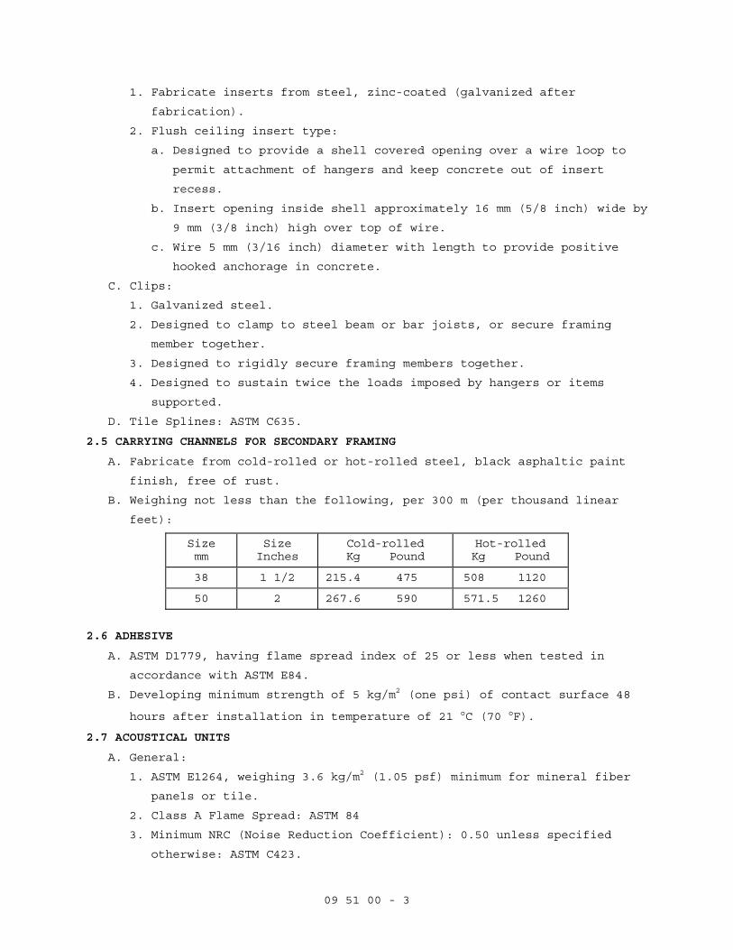
09 51 00 - 3
1. Fabricate inserts from steel, zinc-coated (galvanized after
fabrication).
2. Flush ceiling insert type:
a. Designed to provide a shell covered opening over a wire loop to
permit attachment of hangers and keep concrete out of insert
recess.
b. Insert opening inside shell approximately 16 mm (5/8 inch) wide by
9 mm (3/8 inch) high over top of wire.
c. Wire 5 mm (3/16 inch) diameter with length to provide positive
hooked anchorage in concrete.
C. Clips:
1. Galvanized steel.
2. Designed to clamp to steel beam or bar joists, or secure framing
member together.
3. Designed to rigidly secure framing members together.
4. Designed to sustain twice the loads imposed by hangers or items
supported.
D. Tile Splines: ASTM C635.
2.5 CARRYING CHANNELS FOR SECONDARY FRAMING
A. Fabricate from cold-rolled or hot-rolled steel, black asphaltic paint
finish, free of rust.
B. Weighing not less than the following, per 300 m (per thousand linear
feet):
Size mm
Size Inches
Cold-rolled Kg Pound
Hot-rolled Kg Pound
38 1 1/2 215.4 475 508 1120
50 2 267.6 590 571.5 1260
2.6 ADHESIVE
A. ASTM D1779, having flame spread index of 25 or less when tested in
accordance with ASTM E84.
B. Developing minimum strength of 5 kg/m2 (one psi) of contact surface 48
hours after installation in temperature of 21 °C (70 °F).
2.7 ACOUSTICAL UNITS
A. General:
1. ASTM E1264, weighing 3.6 kg/m2 (1.05 psf) minimum for mineral fiber
panels or tile.
2. Class A Flame Spread: ASTM 84
3. Minimum NRC (Noise Reduction Coefficient): 0.50 unless specified
otherwise: ASTM C423.

09 51 00 - 4
4. Minimum CAC (Ceiling Attenuation Class): 35 range unless specified
otherwise: ASTM E413.
5. Manufacturers standard finish, minimum Light Reflectance (LR)
coefficient of 0.87 on the exposed surfaces, except as specified
otherwise in Section SCHEDULE FOR FINISHES.
6. Lay-in panels: 609 x 609 mm (2 x 2 feet), with beveled tegular edges.
B. Type III Units - Mineral base with painted finish, Form 2 - Water
felted, minimum 16 mm (5/8 inch) thick.
2.8 ACCESS IDENTIFICATION
A. Markers:
1. Use colored markers with pressure sensitive adhesive on one side.
2. Make colored markers of paper of plastic, 6 to 9 mm (1/4 to 3/8 inch)
in diameter.
B. Use markers of the same diameter throughout building.
C. Color Code: Use following color markers for service identification:
Color...................Service
Red.....................Sprinkler System: Valves and Controls
Green...................Domestic Water: Valves and Controls
Yellow..................Chilled Water and Heating Water
Orange..................Ductwork: Fire Dampers
Blue....................Ductwork: Dampers and Controls
Black...................Gas: Laboratory, Medical, Air and Vacuum
PART 3 EXECUTIONS
3.1 CEILING TREATMENT
A. Treatment of ceilings shall include sides and soffits of ceiling beams,
furred work 600 mm (24 inches) wide and over, and vertical surfaces at
changes in ceiling heights unless otherwise shown.
B. Lay out acoustical units symmetrically about center lines of each room
or space unless shown otherwise on reflected ceiling plan.
C. Moldings:
1. Install metal wall molding at perimeter of room, column, or edge at
vertical surfaces.
2. Install special shaped molding at changes in ceiling heights and at
other breaks in ceiling construction to support acoustical units and
to conceal their edges.
D. Perimeter Seal:
1. Install perimeter seal between vertical leg of wall molding and
finish wall, partition, and other vertical surfaces.
2. Install perimeter seal to finish flush with exposed faces of
horizontal legs of wall molding.
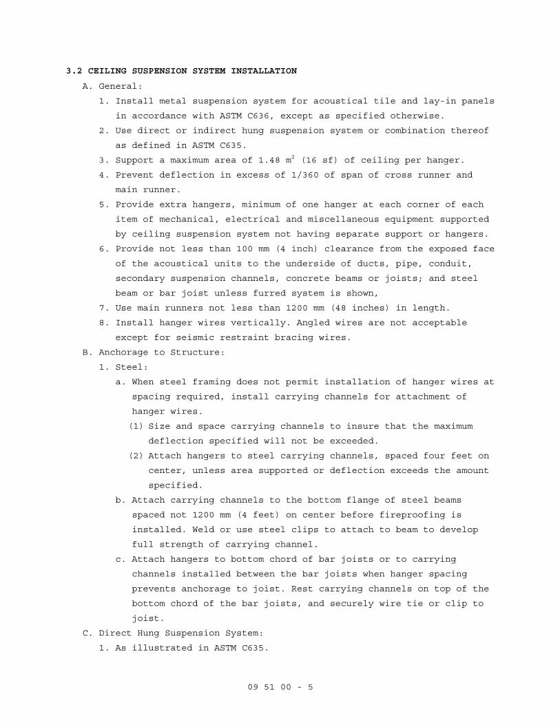
09 51 00 - 5
3.2 CEILING SUSPENSION SYSTEM INSTALLATION
A. General:
1. Install metal suspension system for acoustical tile and lay-in panels
in accordance with ASTM C636, except as specified otherwise.
2. Use direct or indirect hung suspension system or combination thereof
as defined in ASTM C635.
3. Support a maximum area of 1.48 m2 (16 sf) of ceiling per hanger.
4. Prevent deflection in excess of 1/360 of span of cross runner and
main runner.
5. Provide extra hangers, minimum of one hanger at each corner of each
item of mechanical, electrical and miscellaneous equipment supported
by ceiling suspension system not having separate support or hangers.
6. Provide not less than 100 mm (4 inch) clearance from the exposed face
of the acoustical units to the underside of ducts, pipe, conduit,
secondary suspension channels, concrete beams or joists; and steel
beam or bar joist unless furred system is shown,
7. Use main runners not less than 1200 mm (48 inches) in length.
8. Install hanger wires vertically. Angled wires are not acceptable
except for seismic restraint bracing wires.
B. Anchorage to Structure:
1. Steel:
a. When steel framing does not permit installation of hanger wires at
spacing required, install carrying channels for attachment of
hanger wires.
(1) Size and space carrying channels to insure that the maximum
deflection specified will not be exceeded.
(2) Attach hangers to steel carrying channels, spaced four feet on
center, unless area supported or deflection exceeds the amount
specified.
b. Attach carrying channels to the bottom flange of steel beams
spaced not 1200 mm (4 feet) on center before fireproofing is
installed. Weld or use steel clips to attach to beam to develop
full strength of carrying channel.
c. Attach hangers to bottom chord of bar joists or to carrying
channels installed between the bar joists when hanger spacing
prevents anchorage to joist. Rest carrying channels on top of the
bottom chord of the bar joists, and securely wire tie or clip to
joist.
C. Direct Hung Suspension System:
1. As illustrated in ASTM C635.
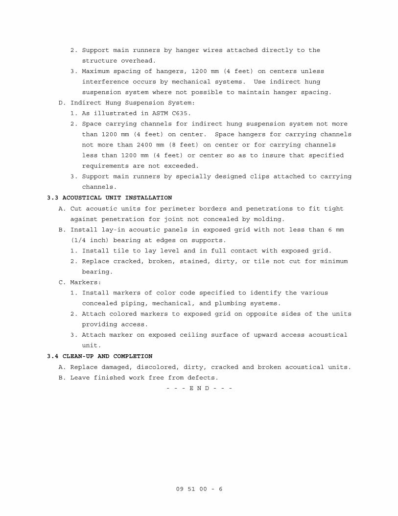
09 51 00 - 6
2. Support main runners by hanger wires attached directly to the
structure overhead.
3. Maximum spacing of hangers, 1200 mm (4 feet) on centers unless
interference occurs by mechanical systems. Use indirect hung
suspension system where not possible to maintain hanger spacing.
D. Indirect Hung Suspension System:
1. As illustrated in ASTM C635.
2. Space carrying channels for indirect hung suspension system not more
than 1200 mm (4 feet) on center. Space hangers for carrying channels
not more than 2400 mm (8 feet) on center or for carrying channels
less than 1200 mm (4 feet) or center so as to insure that specified
requirements are not exceeded.
3. Support main runners by specially designed clips attached to carrying
channels.
3.3 ACOUSTICAL UNIT INSTALLATION
A. Cut acoustic units for perimeter borders and penetrations to fit tight
against penetration for joint not concealed by molding.
B. Install lay-in acoustic panels in exposed grid with not less than 6 mm
(1/4 inch) bearing at edges on supports.
1. Install tile to lay level and in full contact with exposed grid.
2. Replace cracked, broken, stained, dirty, or tile not cut for minimum
bearing.
C. Markers:
1. Install markers of color code specified to identify the various
concealed piping, mechanical, and plumbing systems.
2. Attach colored markers to exposed grid on opposite sides of the units
providing access.
3. Attach marker on exposed ceiling surface of upward access acoustical
unit.
3.4 CLEAN-UP AND COMPLETION
A. Replace damaged, discolored, dirty, cracked and broken acoustical units.
B. Leave finished work free from defects.
- - - E N D - - -
09 91 00 - 1
SECTION 09 91 00 PAINTING
PART 1-GENERAL
1.1 DESCRIPTION
A. Section specifies field painting.
B. Section specifies prime coats that may be applied in shop under other
sections.
C. Painting includes shellacs, stains, varnishes, coatings specified, and
striping or markers and identity markings.
1.2 RELATED WORK
1.3 SUBMITTALS
A. Manufacturer's Literature and Data:
Before work is started, or sample panels are prepared, submit
manufacturer's literature, the current Master Painters Institute (MPI)
"Approved Product List" indicating brand label, product name and product
code as of the date of contract award, will be used to determine
compliance with the submittal requirements of this specification. The
Contractor may choose to use subsequent MPI "Approved Product List",
however, only one list may be used for the entire contract and each
coating system is to be from a single manufacturer. All coats on a
particular substrate must be from a single manufacturer. No variation
from the MPI "Approved Product List" where applicable is acceptable.
C. Sample Panels:
1. After painters' materials have been approved and before work is
started submit sample panels showing each type of finish and color
specified.
2. Panels to show color: Composition board, 100 by 250 by 3 mm (4 inch
by 10 inch by 1/8 inch).
3. Panel to show transparent finishes: Wood of same species and grain
pattern as wood approved for use, 100 by 250 by 3 mm (4 inch by 10
inch face by 1/4 inch) thick minimum, and where both flat and edge
grain will be exposed, 250 mm (10 inches) long by sufficient size, 50
by 50 mm (2 by 2 inch) minimum or actual wood member to show complete
finish.
4. Attach labels to panel stating the following:
a. Federal Specification Number or manufacturers name and product
number of paints used.
b. Specification code number specified in Section, 09 06 00, SCHEDULE
FOR FINISHES.
c. Product type and color.
09 91 00 - 2
d. Name of project.
5. Strips showing not less than 50 mm (2 inch) wide strips of undercoats
and 100 mm (4 inch) wide strip of finish coat.
D. Sample of identity markers if used.
E. Manufacturers' Certificates indicating compliance with specified
requirements:
1. Manufacturer's paint substituted for Federal Specification paints meets or exceeds performance of paint specified.
2. Epoxy coating. 1.4 DELIVERY AND STORAGE
A. Deliver materials to site in manufacturer's sealed container marked to
show following:
1. Name of manufacturer.
2. Product type.
3. Batch number.
4. Instructions for use.
5. Safety precautions.
B. In addition to manufacturer's label, provide a label legibly printed as
following:
1. Federal Specification Number, where applicable, and name of material.
2. Surface upon which material is to be applied.
3. If paint or other coating, state coat types; prime, body or finish.
C. Maintain space for storage, and handling of painting materials and
equipment in a neat and orderly condition to prevent spontaneous
combustion from occurring or igniting adjacent items.
D. Store materials at site at least 24 hours before using, at a temperature
between 18 and 30 degrees C (65 and 85 degrees F).
1.5 APPLICABLE PUBLICATIONS
A. Publications listed below form a part of this specification to the
extent referenced. Publications are referenced in the text by basic
designation only.
B. American Conference Of Governmental Industrial Hygienists (ACGIH):
ACGIH TLV-BKLT-1992.....Threshold Limit Values (TLV) for Chemical
Substances and Physical Agents and Biological
Exposure Indices (BEIs)
ACGIH TLV-DOC...........Documentation of Threshold Limit Values and
Biological Exposure Indices, (Sixth Edition)
C. American National Standards Institute (ANSI):
A13.1-96................Scheme for the Identification of Piping Systems
D. American Society for Testing and Materials (ASTM):
09 91 00 - 3
D260-86..........Boiled Linseed Oil
E. Commercial Item Description (CID):
A-A-1272................Plaster, Gypsum (Spackling Compound)
A-A-1555................Water Paint, Powder (Cementitious, White and
Colors) (WPC) (cancelled)
F. Federal Specifications (Fed Spec):
P-W-155C................Wax Floor, Water-Emulsion INT AMD 1
TT-F-322D...............Filler, Two-Component Type, For Dents, Cracks
INT AMD 1...............Small-Hole and Blow-Holes
TT-F-340C...............Filler, Wood, Plastic
G. Master Painters Institute (MPI):
No. 18-02...............Organic Zinc Rich Coating
No. 26-02...............Cementitious Galvanized Metal Primer
No. 31-02...............Polyurethane, Moisture Cured, Clear Gloss (PV)
No. 36-02...............Knot Sealer
No. 43-02...............Interior Satin Latex
No. 44-02...............Interior Low Sheen Latex
No. 45-02...............Interior Primer Sealer
No. 46-02...............Interior Enamel Undercoat
No. 47-02...............Interior Alkyd, Semi-Gloss (AK)
No. 48-02...............Interior Alkyd, Gloss (AK)
No. 49-02...............Interior Alkyd, Flat (AK)
No. 50-02...............Interior Latex Primer Sealer
No. 51-02...............Interior Alkyd, Eggshell
No. 52-02...............Interior Latex, MPI Gloss Level 3 (LE)
No. 53-02...............Interior Latex, Flat, MPI Gloss Level 1 (LE)
No. 54-02...............Interior Latex, Semi-Gloss, MPI Gloss Level 5
(LE)
No. 71-02...............Polyurethane, Moisture Cured, Clear, Flat (PV)
No. 77-02...............Epoxy Cold Cured, Gloss (EC)
No. 79-02...............Marine Alkyd Metal Primer
No. 90-02...............Interior Wood Stain, Semi-Transparent (WS)
No. 91-02...............Wood Filler Paste
No. 94-02...............Exterior Alkyd, Semi-Gloss (EO)
No. 95-02...............Fast Drying Metal Primer
No. 98-02...............High Build Epoxy Coating
No. 101-02..............Cold Curing Epoxy Primer
No. 108-02..............High Build Epoxy Marine Coating (EC)
No. 114-02..............Interior Latex, Gloss (LE) and (LG)
No. 119-02..............Exterior Latex, High Gloss (acrylic) (AE)

09 91 00 - 4
No. MPI 135-02..........Non-Cementitious Galvanized Primer
H. Steel Structures Painting Council (SSPC):
SSPC SP 1-00............Solvent Cleaning
SSPC SP 2-00............Hand Tool Cleaning
SSPC SP 3-00............Power Tool Cleaning
I. Western Wood Products Association (WWPA):
Research Note 312- Revised Jan 30, 1985 Painting Over Knots
PART 2 - PRODUCTS
2.1 MATERIALS
A. Floor Wax: Fed Spec P-W-155 (Wax Floor, Water-Emulsion).
B. Putty: Fed Spec A-A-378, Type II (Putty, Linseed Oil Type).
C. Cementitious Paint (CEP): TT-P-1411A [Paint, Copolymer-Resin,
Cementitious (CEP)], Type II for interior use.
D. Wood Sealer: MPI 31 (gloss) or MPI 71 (flat) thinned with thinner
recommended by manufacturer at rate of about one part of thinner to four
parts of varnish.
E. Plastic Tape:
1. Pigmented vinyl plastic film in colors as specified in Section 09 06
00, SCHEDULE FOR FINISHES.
2. Pressure sensitive adhesive back.
3. Widths as shown.
F. Identity markers options:
1. Pressure sensitive vinyl markers.
2. Snap-on coil plastic markers.
G. Organic Zinc rich Coating (HR): MPI 22.
H. Cementitious Galvanized Metal Primer: MPI 26.
I. Knot Sealer: MPI 36.
J. Interior Satin Latex: MPI 43.
K. Interior Low Sheen Latex: MPI 44.
L. Interior Primer Sealer: MPI 45.
M. Interior Enamel Undercoat: MPI 47.
N. Interior Alkyd, Semi-Gloss (AK): MPI 47.
O. Interior Alkyd, Gloss (AK): MPI 49.
P. Interior Latex Primer Sealer: MPI 50.
Q. Interior Alkyd, Eggshell: MPI 51
R. Interior Latex, MPI Gloss Level 3 (LE): MPI 52.
S. Interior Latex, Flat, MPI Gloss Level 1 (LE): MPI 53.
T. Interior Latex, Semi-Gloss, MPI Gloss Level 5 (LE): MPI 54.
U. Epoxy Cold Cured, Gloss (EC): MPI 77.
V. Marine Alkyd Metal primer: MPI 79.
09 91 00 - 5
W. Interior Wood Stain, Semi-Transparent (WS): MPI 90.
X. Wood Filler Paste: MPI 91.
Y. Fast Drying Metal Primer: MPI 95.
Z. High Build Epoxy Coating: MPI 98.
AA. Cold Curing Epoxy Primer: MPI 101.
BB. High Build Epoxy Marine Coating (EC): MPI 108.
CC. Interior latex, Gloss (LE) and (LG): MPI 114.
DD. Exterior Latex, High Gloss (acrylic) (AE): MPI 119.
EE. Waterborne Galvanized Primer: MPI 134.
FF. Non-Cementitious Galvanized Primer: MPI 135.
2.2 PAINT PROPERTIES
A. Use ready-mixed (including colors), except two component epoxies,
polyurethanes, polyesters, paints having metallic powders packaged
separately and paints requiring specified additives.
B. Where no requirements are given in the referenced specifications for
primers, use primers with pigment and vehicle, compatible with substrate
and finish coats specified.
2.3 REGULATORY REQUIREMENTS
A. Paint materials shall conform to the restrictions of the local
Environmental and Toxic Control jurisdiction.
1. Volatile Organic Compounds (VOC): VOC content of paint materials
shall not exceed local, state or district requirements.
2. Lead-Base Paint:
a. Comply with Section 410 of the Lead-Based Paint Poisoning
Prevention Act, as amended, and with implementing regulations
promulgated by Secretary of Housing and Urban Development.
b. Regulations concerning prohibition against use of lead-based paint
in federal and federally assisted construction, or rehabilitation
of residential structures are set forth in Subpart F, Title 24,
Code of Federal Regulations, Department of Housing and Urban
Development.
3. Asbestos: Materials shall not contain asbestos.
4. Chromate, Cadmium, Mercury, and Silica: Materials shall not contain
zinc-chromate, strontium-chromate, Cadmium, mercury or mercury
compounds or free crystalline silica.
5. Human Carcinogens: Materials shall not contain any of the ACGIH-BKLT
and ACGHI-DOC confirmed or suspected human carcinogens.

09 91 00 - 6
PART 3 - EXECUTION
3.1 JOB CONDITIONS
A. Safety: Observe required safety regulations and manufacturer's warning
and instructions for storage, handling and application of painting
materials.
1. Take necessary precautions to protect personnel and property from
hazards due to falls, injuries, toxic fumes, fire, explosion, or
other harm.
2. Deposit soiled cleaning rags and waste materials in metal containers
approved for that purpose. Dispose of such items off the site at end
of each days work.
B. Atmospheric and Surface Conditions:
1. Do not apply coating when air or substrate conditions are:
a. Less than 3 degrees C (5 degrees F) above dew point.
b. Below 10 degrees C (50 degrees F) or over 35 degrees C (95 degrees
F), unless specifically pre-approved by the Contracting Officer
and the product manufacturer. Under no circumstances shall
application conditions exceed manufacturer recommendations.
2. Maintain interior temperatures until paint dries hard.
3. Do not paint in direct sunlight or on surfaces that the sun will soon
warm.
4. Apply only on clean, dry and frost free surfaces except as follows:
a. Apply water thinned acrylic and cementitious paints to damp (not
wet) surfaces where allowed by manufacturer's printed
instructions.
5. Varnishing:
a. Apply in clean areas and in still air.
b. Before varnishing vacuum and dust area.
c. Immediately before varnishing wipe down surfaces with a tack rag.
3.2 SURFACE PREPARATION
A. Method of surface preparation is optional, provided results of finish
painting produce solid even color and texture specified with no
overlays.
B. General:
1. Remove prefinished items not to be painted such as lighting fixtures,
escutcheon plates, hardware, trim, and similar items for
reinstallation after paint is dried.
2. Remove items for reinstallation and complete painting of such items
and adjacent areas when item or adjacent surface is not accessible or
finish is different.

09 91 00 - 7
3. See other sections of specifications for specified surface conditions
and prime coat.
4. Clean surfaces for painting with materials and methods compatible
with substrate and specified finish. Remove any residue remaining
from cleaning agents used.
C. Wood:
1. Sand to a smooth even surface and then dust off.
2. Sand surfaces showing raised grain smooth between each coat.
3. Wipe surface with a tack rag prior to applying finish.
4. Surface painted with an opaque finish:
a. Coat knots, sap and pitch streaks with MPI 36 (Knot Sealer) before
applying paint.
b. Apply two coats of MPI 36 (Knot Sealer) over large knots.
5. After application of prime or first coat of stain, fill cracks, nail
and screw holes, depressions and similar defects with TT-F-340C
(Filler, Wood, Plastic) or A-A-378 (Putty, Linseed Oil Type). Use TT-
F-340C (Filler, Wood, Plastic) for transparent finish, to match wood.
Sand the surface to make smooth and finish flush with adjacent
surface.
6. Before applying finish coat, reapply TT-340C (Filler, Wood, Plastic)
or A-A-378 (Putty, Linseed Oil Type) if required, and sand surface to
remove surface blemishes. Finish flush with adjacent surfaces.
7. Fill open grained wood such as oak, walnut, ash and mahogany with MPI
91 (Wood Filler Paste), colored to match wood color.
a. Thin filler in accordance with manufacturer's instructions for
application.
b. Remove excess filler, wipe as clean as possible, dry, and sand as
specified.
D. Ferrous Metals:
1. Remove oil, grease, soil, drawing and cutting compounds, flux and
other detrimental foreign matter in accordance with SSPC-SP 1
(Solvent Cleaning).
2. Remove loose mill scale, rust, and paint, by hand or power tool
cleaning, as defined in SSPC-SP 2 (Hand Tool Cleaning) and SSPC-SP 3
(Power Tool Cleaning). Exception: where high temperature aluminum
paint is used, prepare surface in accordance with paint
manufacturer's instructions.
3. Fill dents, holes and similar voids and depressions in flat exposed
surfaces of hollow steel doors and frames, access panels, and similar
items specified to have semi-gloss or gloss finish with TT-F-322D

09 91 00 - 8
(Filler, Two-Component Type, For Dents, Small Holes and Blow-Holes).
Finish flush with adjacent surfaces.
a. This includes flat head countersunk screws used for permanent
anchors.
b. Do not fill screws of item intended for removal such as glazing
beads.
4. Spot prime abraded and damaged areas in shop prime coat that expose
bare metal with same type of paint used for prime coat. Feather edge
of spot prime to produce smooth finish coat.
5. Spot prime abraded and damaged areas that expose bare metal of
factory finished items with paint as recommended by manufacturer of
item.
E. Zinc-Coated (Galvanized) Metal Surfaces Specified Painted:
1. Clean surfaces to remove grease, oil and other deterrents to paint
adhesion in accordance with SSPC-SP 1 (Solvent Cleaning).
2. Spot coat abraded and damaged areas of zinc-coating which expose base
metal on hot-dip zinc-coated items with MPI 18 (Organic Zinc Rich
Coating). Prime or spot prime with MPI 134 (Waterborne Galvanized
Primer) or MPI 135 (Non- Cementitious Galvanized Primer) depending on
finish coat compatibility.
F. Gypsum Board:
1. Remove finishing materials.
2. Remove dust, dirt, and other deterrents to paint adhesion.
3. Fill holes, cracks, and other depressions with CID-A-A-1272A
[Plaster, Gypsum (Spackling Compound) finished flush with adjacent
surface, with texture to match texture of adjacent surface. Patch
holes over 25 mm (1-inch) in diameter as specified in Section for
plaster or gypsum board.
3.3 PAINT PREPARATION
A. Thoroughly mix painting materials to ensure uniformity of color,
complete dispersion of pigment and uniform composition.
B. Do not thin unless necessary for application and when finish paint is
used for body and prime coats. Use materials and quantities for thinning
as specified in manufacturer's printed instructions.
C. Remove paint skins, then strain paint through commercial paint strainer
to remove lumps and other particles.
D. Mix two component and two part paint and those requiring additives in
such a manner as to uniformly blend as specified in manufacturer's
printed instructions unless specified otherwise.

09 91 00 - 9
E. For tinting required to produce exact shades specified, use color
pigment recommended by the paint manufacturer.
3.4 APPLICATION
A. Start of surface preparation or painting will be construed as acceptance
of the surface as satisfactory for the application of materials.
B. Unless otherwise specified, apply paint in three coats; prime, body, and
finish. When two coats applied to prime coat are the same, first coat
applied over primer is body coat and second coat is finish coat.
C. Apply each coat evenly and cover substrate completely.
D. Allow not less than 48 hours between application of succeeding coats,
except as allowed by manufacturer's printed instructions, and approved
by Resident Engineer.
E. Finish surfaces to show solid even color, free from runs, lumps, brush
marks, laps, holidays, or other defects.
F. Apply by brush, roller or spray, except as otherwise specified.
G. Do not spray paint in existing occupied spaces unless approved by
Resident Engineer, except in spaces sealed from existing occupied
spaces.
1. Apply painting materials specifically required by manufacturer to be
applied by spraying.
2. In areas, where paint is applied by spray, mask or enclose with
polyethylene, or similar air tight material with edges and seams
continuously sealed including items specified in WORK NOT PAINTED,
motors, controls, telephone, and electrical equipment, fronts of
sterilizes and other recessed equipment and similar prefinished
items.
H. Do not paint in closed position operable items such as access doors and
panels, and similar items.
3.5 PRIME PAINTING
A. After surface preparation prime surfaces before application of body and
finish coats, except as otherwise specified.
B. Spot prime and apply body coat to damaged and abraded painted surfaces
before applying succeeding coats.
C. Additional field applied prime coats over shop or factory applied prime
coats are not required except for exterior exposed steel apply an
additional prime coat.
D. Prime rebates for stop and face glazing of wood, and for face glazing of
steel.
E. Wood:
1. Use same kind of primer specified for exposed face surface.
09 91 00 - 10
a. Interior wood except for transparent finish: MPI 45 (Interior
Primer Sealer) or MPI 46 (Interior Enamel Undercoat), thinned if
recommended by manufacturer.
b. Transparent finishes as specified under Transparent Finishes on
Wood except Floors.
2. Apply one coat of primer MPI 7 (Exterior Oil Wood Primer) or MPI 5
(Exterior Alkyd Wood Primer) or sealer MPI 45 (Interior Primer
Sealer) or MPI 46 (Interior Enamel Undercoat) as soon as delivered to
site to surfaces of unfinished woodwork, except concealed surfaces of
shop fabricated or assembled millwork and surfaces specified to have
varnish, stain or natural finish.
F. Metals except boilers, incinerator stacks, and engine exhaust pipes:
1. Steel and iron: MPI 95 (Fast Drying Metal Primer).
2. Zinc-coated steel and iron: MPI 134 (Waterborne Galvanized Primer) or
MPI 135 (Non-Cementitious Galvanized Primer).
G. Gypsum Board:
1. Surfaces scheduled to have MPI 53 (Interior Latex, Flat), MPI Gloss
Level 1 LE)), MPI 52 (Interior Latex, MPI Gloss Level 3 (LE)) and MPI
54 (Interior Latex, Semi-Gloss, MPI Gloss Level 5 (LE)) finish: Use
MPI 53 (Interior Latex, MPI Gloss Level 3 (LE)), MPI 52 (Interior
Latex, MPI Gloss Level 3 (LE)), and MPI 54 (Interior Latex, Semi-
Gloss, MPI Gloss Level 5 (LE)).
2. Primer: MPI 50(Interior Latex Primer Sealer) except use MPI 45
(Interior Primer Sealer) in shower and bathrooms.
3. Surfaces scheduled to receive vinyl coated fabric wallcovering:
Use MPI 45 (Interior Primer Sealer).
4. Use MPI 101 (Cold Curing Epoxy Primer) for surfaces scheduled to
receive MPI 77 (Epoxy Cold Cured, Gloss (EC) or MPI 98 (High Build
Epoxy Coating).
3.6 INTERIOR FINISHES
A. Apply following finish coats over prime coats in spaces or on surfaces
specified in Section 09 06 00, SCHEDULE FOR FINISHES.
B. Metal Work:
1. Apply to exposed surfaces.
2. Omit body and finish coats on surfaces concealed after installation
except electrical conduit containing conductors over 600 volts.
3. Ferrous Metal, Galvanized Metal, and Other Metals Scheduled:
a. Apply two coats of MPI 47 (Interior Alkyd, Semi-Gloss (AK)) unless
specified otherwise.
C. Gypsum Board:
09 91 00 - 11
1. One coat of MPI 45 (Interior Primer Sealer) or MPI 46 (Interior
Enamel Undercoat) plus one coat of MPI 139 (Interior High Performance
Latex, MPI Gloss level 3 (LL)).
2. Two coats of MPI 138 (Interior High Performance Latex, MPI Gloss
Level 2 (LF)).
3. One coat of MPI 45 (Interior Primer Sealer) or MPI 46 (Interior
Enamel Undercoat) plus one coat of MPI 54 (Interior Latex, Semi-
Gloss, MPI Gloss Level 5 (LE)).
D. Wood:
1. Sanding:
a. Use 220-grit sandpaper.
b. Sand sealers and varnish between coats.
c. Sand enough to scarify surface to assure good adhesion of
subsequent coats, to level roughly applied sealer and varnish, and
to knock off "whiskers" of any raised grain as well as dust
particles.
2. Sealers:
a. Apply sealers specified except sealer may be omitted where
pigmented, penetrating, or wiping stains containing resins are
used.
b. Allow manufacturer's recommended drying time before sanding, but
not less than 24 hours or 36 hours in damp or muggy weather.
c. Sand as specified.
3. Paint Finish:
a. One coat of MPI 46 (Interior Enamel Undercoat) plus one coat of
MPI 47 (Interior Alkyd, Semi-Gloss (AK)) (SG).
4. Transparent Finishes on Wood Except Floors.
a. Natural Finish:
1) One coat of sealer as written in 2.1 E.
2) Two coats of MPI 71 (Polyurethane, Moisture Cured, Clear Flat
(PV).
b. Stain Finish:
1) One coat of MPI 90 (Interior Wood Stain, Semi-Transparent
(WS)).
2) Use wood stain of type and color required to achieve finish
specified. Do not use varnish type stains.
3) One coat of sealer as written in 2.1 E.
4) Two coats of MPI 71 (Polyurethane, Moisture Cured, Clear Flat
(PV).
c. Varnish Finish:
09 91 00 - 12
1) One coat of sealer as written in 2.1 E.
2) Two coats of MPI 71 (Polyurethane, Moisture Cured, Clear Flat
(PV).
E. Miscellaneous:
1. Apply where specified in Section 09 06 00, SCHEDULE FOR FINISHES.
3.7 REFINISHING EXISTING PAINTED SURFACES
A. Clean, patch and repair existing surfaces as specified under surface
preparation.
B. Remove and reinstall items as specified under surface preparation.
C. Remove existing finishes or apply separation coats to prevent non
compatible coatings from having contact.
D. Patched or Replaced Areas in Surfaces and Components: Apply spot prime
and body coats as specified for new work to repaired areas or replaced
components.
E. Except where scheduled for complete painting apply finish coat over
plane surface to nearest break in plane, such as corner, reveal, or
frame.
F. Refinish areas as specified for new work to match adjoining work unless
specified or scheduled otherwise.
G. Coat knots and pitch streaks showing through old finish with MPI 36
(Knot Sealer) before refinishing.
H. Sand or dull glossy surfaces prior to painting.
I. Sand existing coatings to a feather edge so that transition between new
and existing finish will not show in finished work.
3.8 PAINT COLOR
A. Color and gloss of finish coats shall be selected to match adjacent
surfaces and components in color and finish as closely as possible.
Provide three samples of each color and finish for approval by the
Contracting Officer or their Representative prior to application of any
coatings.
B. Coat Colors:
1. Color of priming coat: Lighter than body coat.
2. Color of body coat: Lighter than finish coat.
3. Color prime and body coats to not show through the finish coat and to
mask surface imperfections or contrasts.
C. Painting, Caulking, Closures, and Fillers Adjacent to Casework:
1. Paint to match color of casework where casework has a paint finish.
2. Paint to match color of wall where casework is stainless steel,
plastic laminate, or varnished wood.
09 91 00 - 13
3.9 MECHANICAL AND ELECTRICAL WORK FIELD PAINTING SCHEDULE
A. Field painting of mechanical and electrical consists of cleaning,
touching-up abraded shop prime coats, and applying prime, body and
finish coats to materials and equipment if not factory finished in space
scheduled to be finished.
B. Paint various systems specified in Divisions 23, and 24.
C. Paint after tests have been completed.
D. Omit prime coat from factory prime-coated items.
E. Finish painting of mechanical and electrical equipment is not required
when located in interstitial spaces, above suspended ceilings, in
concealed areas such as pipe and electric closets, pipe basements, pipe
tunnels, trenches, attics, roof spaces, shafts and furred spaces except
on electrical conduit containing feeders 600 volts or more.
F. Omit field painting of items specified in paragraph, Building and
Structural WORK NOT PAINTED.
G. Color:
1. Paint items to match surrounding surfaces.
2. Paint colors to match surrounding, except for following:
a. White: Exterior unfinished surfaces of enameled plumbing
fixtures. Insulation coverings on breeching and uptake inside
boiler house, drums and drum-heads, oil heaters, condensate tanks
and condensate piping.
b. Gray: Heating, ventilating, air conditioning and refrigeration
equipment (except as required to match surrounding surfaces), and
water and sewage treatment equipment and sewage ejection
equipment.
c. Aluminum Color:. Ferrous metal on outside of boilers and in
connection with boiler settings including supporting doors and
door frames and fuel oil burning equipment, and steam generation
system (bare piping, fittings, hangers, supports, valves, traps
and miscellaneous iron work in contact with pipe).
d. Federal Safety Red: Exposed fire protection piping hydrants, post
indicators, electrical conducts containing fire alarm control
wiring, and fire alarm equipment.
e. Federal Safety Orange: .Entire lengths of electrical conduits
containing feeders 600 volts or more.
I. Apply paint systems on properly prepared and primed surface as follows:
1. Interior Locations:
a. Apply two coats of MPI 47 (Interior Alkyd, Semi-Gloss (AK)) to
following items:

09 91 00 - 14
1) Metal under 94 degrees C (200 degrees F) of items such as bare
piping, fittings, hangers and supports.
2) Equipment and systems such as hinged covers and frames for
control cabinets and boxes, cast-iron radiators, electric
conduits and panel boards.
3) Heating, ventilating, air conditioning, plumbing equipment, and
machinery having shop prime coat and not factory finished.
b. Paint electrical conduits containing cables rated 600 volts or
more using two coats of MPI 94 (Exterior Alkyd, Semi-gloss (EO))
in the Federal Safety Orange color in exposed and concealed spaces
full length of conduit.
2. Other exposed locations:
a. Cloth jackets of insulation of ducts and pipes in connection with
plumbing, air conditioning, ventilating refrigeration and heating
systems: One coat of MPI 50 (Interior Latex Primer Sealer) and
one coat of MPI 10 (Exterior Latex, Flat (AE)).
3.10 BUILDING AND STRUCTURAL WORK FIELD PAINTING
3.11 IDENTITY PAINTING SCHEDULE
A. Identify designated service in accordance with ANSI A13.1, unless
specified otherwise, on exposed piping, piping above removable ceilings,
piping in accessible pipe spaces, interstitial spaces, and piping behind
access panels.
1. Legend may be identified using 2.1 F options or by stencil
applications.
2. Apply legends adjacent to changes in direction, on branches, where
pipes pass through walls or floors, adjacent to operating accessories
such as valves, regulators, strainers and cleanouts a minimum of 12
000 mm (40 feet) apart on straight runs of piping. Identification
next to plumbing fixtures is not required.
3. Locate Legends clearly visible from operating position.
4. Use arrow to indicate direction of flow.
5. Identify pipe contents with sufficient additional details such as
temperature, pressure, and contents to identify possible hazard.
Insert working pressure shown on drawings where asterisk appears for
High, Medium, and Low Pressure designations as follows:
a. High Pressure - 414 kPa (60 psig) and above.
b. Medium Pressure - 104 to 413 Kpa (15 to 59 psig).
c. Low Pressure - 103 kPa (14 psig) and below.
d. Add Fuel oil grade numbers.

09 91 00 - 15
6. Legend name in full or in abbreviated form as follows:
COLOR OF COLOR OF COLOR OF LEGEND
PIPING EXPOSED PIPING BACKGROUND LETTERS BBREVIATIONS
Blow-off Yellow Black Blow-off
Boiler Feedwater Yellow Black Blr Feed
A/C Condenser Water Supply Green White A/C Cond Wtr Sup
A/C Condenser Water Return Green White A/C Cond Wtr Ret
Chilled Water Supply Green White Ch. Wtr Sup
Chilled Water Return Green White Ch. Wtr Ret
Shop Compressed Air Yellow Black Shop Air
Air-Instrument Controls Green White Air-Inst Cont
Drain Line Green White Drain
Emergency Shower Green White Emg Shower
High Pressure Steam Yellow Black H.P. ______*
High Pressure Condensate Return Yellow Black H.P. Ret ____*
Medium Pressure Steam Yellow Black M. P. Stm ____*
Medium Pressure Condensate Return Yellow Black M.P. Ret _____*
Low Pressure Steam Yellow Black L.P. Stm _____*
Low Pressure Condensate Return Yellow Black L.P. Ret _____*
High Temperature Water Supply Yellow Black H. Temp Wtr Sup
High Temperature Water Return Yellow Black H. Temp Wtr Ret
Hot Water Heating Supply Yellow Black H. W. Htg Sup
Hot Water Heating Return Yellow Black H. W. Htg Ret
Gravity Condensate Return Yellow Black Gravity Cond Ret
Pumped Condensate Return Yellow Black Pumped Cond Ret
Vacuum Condensate Return Yellow Black Vac Cond Ret
Fuel Oil - Grade Green White Fuel Oil-Grade __*
Boiler Water Sampling Yellow Black Sample
Chemical Feed Yellow Black Chem Feed
Continuous Blow-Down Yellow Black Cont. B D
Pumped Condensate Black Pump Cond
Pump Recirculating Yellow Black Pump-Recirc.
Vent Line Yellow Black Vent
Alkali Yellow Black Alk
Bleach Yellow Black Bleach
Detergent Yellow Black Det
Liquid Supply Yellow Black Liq Sup
Reuse Water Yellow Black Reuse Wtr
Cold Water (Domestic) White Green White C.W. Dom

09 91 00 - 16
Hot Water (Domestic)
Supply White Yellow Black H.W. Dom
Return White Yellow Black H.W. Dom Ret
Tempered Water White Yellow Black Temp. Wtr
Ice Water
Supply White Green White Ice Wtr
Return White Green White Ice Wtr Ret
Reagent Grade Water Green White RG
Reverse Osmosis Green White RO
Sanitary Waste Green White San Waste
Sanitary Vent Green White San Vent
Storm Drainage Green White St Drain
Pump Drainage Green White Pump Disch
Chemical Resistant Pipe
Waste Yellow Black Acid Waste
Vent Yellow Black Acid Vent
Atmospheric Vent Green White ATV
Silver Recovery Green White Silver Rec
Oral Evacuation Green White Oral Evac
Fuel Gas Yellow Black Gas
Fire Protection Water
Sprinkler Red White Auto Spr
Standpipe Red White Stand
Sprinkler Red White Drain
7. Electrical Conduits containing feeders over 600 volts, paint legends
using 50 mm (2 inch) high black numbers and letters, showing the
voltage class rating. Provide legends where conduits pass through
walls and floors and at maximum 6100 mm (20 foot) intervals in
between. Use labels with yellow background with black border and
words Danger High Voltage Class, Refer to ELECTRICAL for Voltages.
B. Fire Partitions:
1. Identify partitions above ceilings on both sides of partitions except
within shafts in letters not less than 64 mm (2 1/2 inches) high.
2. Stenciled message: "FIRE PARTITION" as applicable.
3. Locate not more than 6100 mm (20 feet) on center on corridor sides of
partitions, and with a least one message per room on room side of
partition.
4. Use semigloss paint of color that contrasts with color of substrate.
C. Identify columns in pipe basements and interstitial space:
09 91 00 - 17
1. Apply stenciled number and letters to correspond with grid numbering
and lettering shown.
2. Paint numbers and letters 100 mm (4 inches) high, locate 450 mm (18
inches) below overhead structural slab.
3. Apply on four sides of interior columns and on inside face only of
exterior wall columns.
4. Color:
a. Use black on concrete columns.
b. Use white or contrasting color on steel columns.
3.12 PROTECTION CLEAN UP, AND TOUCH-UP
A. Protect work from paint droppings and spattering by use of masking, drop
cloths, removal of items or by other approved methods.
B. Upon completion, clean paint from hardware, glass and other surfaces and
items not required to be painted of paint drops or smears.
C. Before final inspection, touch-up or refinished in a manner to produce
solid even color and finish texture, free from defects in work that was
damaged or discolored.
APPENDIX
Coordinate the following abbreviations used in SECTION 09 91 00,
PAINTING, with other Sections, and other COATING SECTIONS listed. Use
the same abbreviation and terms consistently.
Paint or coating Abbreviation
Acrylic Emulsion AE (MPI 10 – flat/MPI 11 – semigloss/MPI 119 -
gloss)
Alkyd Flat Ak (MPI 49)
Alkyd Gloss Enamel G (MPI 48)
Alkyd Semigloss Enamel SG (MPI 47)
Cementitious Paint CEP (TT-P-1411)
Exterior Latex EL (MPI 10 / 11 / 119)
Exterior Oil EO (MPI 9 – gloss/MPI 8 – flat/MPI 94 –
semigloss)
Latex Emulsion LE (MPI 53, flat/MPI 52, eggshell/MPI 54,
semigloss/MPI 114, gloss
Latex Flat LF (MPI 138)
Latex Gloss LG (MPI 114)
Latex Semigloss SG (MPI 141)
Latex Low Luster LL (MPI 139)
Polyurethane Varnish PV (MPI 31 – gloss/MPI 71 - flat)

09 91 00 - 18
Water Paint, Cement WPC (CID-A-A-1555 - Water Paint, Powder).
Wood Stain WS (MPI 90)
- - - E N D - - -
11-10
23 05 11 - 1
SECTION 23 05 11 COMMON WORK RESULTS FOR HVAC
PART 1 - GENERAL
1.1 DESCRIPTION
A. The requirements of this Section apply to all sections of Division 23.
B. Definitions:
1. Exposed: Piping, ductwork, and equipment exposed to view in finished
rooms.
2. Option or optional: Contractor's choice of an alternate material or
method.
3. RE: Resident Engineer
4. COTR: Contracting Officer’s Technical Representative.
1.2 RELATED WORK
A. Section 00 72 00, GENERAL CONDITIONS B. Section 01 00 00, GENERAL REQUIREMENTS C. Section 01 33 23, SHOP DRAWINGS, PRODUCT DATA, and SAMPLES D. Section 23 05 12, GENERAL MOTOR REQUIREMENTS FOR HVAC and STEAM
GENERATION
E. Section 23 05 93, TESTING, ADJUSTING, and BALANCING FOR HVAC
F. Section 23 09 23, DIRECT-DIGITAL CONTROL SYSTEM FOR HVAC
G. Section 23 31 00, HVAC DUCTS and CASINGS
1.3 QUALITY ASSURANCE
A. Mechanical, electrical and associated systems shall be safe, reliable,
efficient, durable, easily and safely operable and maintainable, easily
and safely accessible, and in compliance with applicable codes as
specified. The systems shall be comprised of high quality institutional-
class and industrial-class products of manufacturers that are
experienced specialists in the required product lines. All construction
firms and personnel shall be experienced and qualified specialists in
industrial and institutional HVAC
B. Flow Rate Tolerance for HVAC Equipment: Section 23 05 93, TESTING,
ADJUSTING, AND BALANCING FOR HVAC.
C. Products Criteria:
1. Standard Products: Material and equipment shall be the standard
products of a manufacturer regularly engaged in the manufacture of
the products for at least 3 years (or longer as specified elsewhere).
The design, model and size of each item shall have been in
satisfactory and efficient operation on at least three installations
for approximately three years. However, digital electronics devices,

11-10
23 05 11 - 2
software and systems such as controls, instruments, computer work
station, shall be the current generation of technology and basic
design that has a proven satisfactory service record of at least
three years. See other specification sections for any exceptions
and/or additional requirements.
2. All items furnished shall be free from defects that would adversely
affect the performance, maintainability and appearance of individual
components and overall assembly.
3. Conform to codes and standards as required by the specifications.
Conform to local codes, if required by local authorities such as the
natural gas supplier, if the local codes are more stringent then
those specified. Refer any conflicts to the Resident Engineer.
4. Multiple Units: When two or more units of materials or equipment of
the same type or class are required, these units shall be products of
one manufacturer.
5. Assembled Units: Manufacturers of equipment assemblies, which use
components made by others, assume complete responsibility for the
final assembled product.
6. Nameplates: Nameplate bearing manufacturer's name or identifiable
trademark shall be securely affixed in a conspicuous place on
equipment, or name or trademark cast integrally with equipment,
stamped or otherwise permanently marked on each item of equipment.
7. Asbestos products or equipment or materials containing asbestos shall
not be used.
E. Equipment Service Organizations:
1. HVAC: Products and systems shall be supported by service
organizations that maintain a complete inventory of repair parts and
are located within 50 miles to the site.
F. HVAC Mechanical Systems Welding: Before any welding is performed,
contractor shall submit a certificate certifying that welders comply
with the following requirements:
1. Qualify welding processes and operators for piping according to ASME
"Boiler and Pressure Vessel Code", Section IX, "Welding and Brazing
Qualifications".
2. Comply with provisions of ASME B31 series "Code for Pressure Piping".
3. Certify that each welder has passed American Welding Society (AWS)
qualification tests for the welding processes involved, and that
certification is current.
G. Execution (Installation, Construction) Quality:

11-10
23 05 11 - 3
1. Apply and install all items in accordance with manufacturer's written
instructions. Refer conflicts between the manufacturer's instructions
and the contract drawings and specifications to the Resident Engineer
for resolution. Provide written hard copies or computer files of
manufacturer’s installation instructions to the Resident Engineer at
least two weeks prior to commencing installation of any item.
Installation of the item will not be allowed to proceed until the
recommendations are received. Failure to furnish these
recommendations is a cause for rejection of the material.
2. Provide complete layout drawings required by Paragraph, SUBMITTALS.
Do not commence construction work on any system until the layout
drawings have been approved.
H. Upon request by Government, provide lists of previous installations for
selected items of equipment. Include contact persons who will serve as
references, with telephone numbers and e-mail addresses.
1.4 SUBMITTALS
A. Submit in accordance with Section 01 33 23, SHOP DRAWINGS, PRODUCT DATA,
AND SAMPLES, and with requirements in the individual specification
sections.
B. Contractor shall make all necessary field measurements and
investigations to assure that the equipment and assemblies will meet
contract requirements.
C. If equipment is submitted which differs in arrangement from that shown,
provide drawings that show the rearrangement of all associated systems.
Approval will be given only if all features of the equipment and
associated systems, including accessibility, are equivalent to that
required by the contract.
D. Prior to submitting shop drawings for approval, contractor shall certify
in writing that manufacturers of all major items of equipment have each
reviewed drawings and specifications, and have jointly coordinated and
properly integrated their equipment and controls to provide a complete
and efficient installation.
E. Submittals and shop drawings for interdependent items, containing
applicable descriptive information, shall be furnished together and
complete in a group. Coordinate and properly integrate materials and
equipment in each group to provide a completely compatible and
efficient.
F. Manufacturer's Literature and Data: Submit under the pertinent section
rather than under this section.

11-10
23 05 11 - 4
1. Submit belt drive with the driven equipment. Submit selection data
for specific drives when requested by the Resident Engineer.
2. Submit electric motor data and variable speed drive data with the
driven equipment.
3. Equipment and materials identification.
4. Fire-stopping materials.
5. Hangers, inserts, supports and bracing. Provide load calculations for
variable spring and constant support hangers.
6. Wall, floor, and ceiling plates.
G. HVAC Maintenance Data and Operating Instructions:
1. Maintenance and operating manuals in accordance with Section 01 00
00, GENERAL REQUIREMENTS, Article, INSTRUCTIONS, for systems and
equipment.
2. Provide a listing of recommended replacement parts for keeping in
stock supply, including sources of supply, for equipment. Include in
the listing belts for equipment: Belt manufacturer, model number,
size and style, and distinguished whether of multiple belt sets.
H. Provide copies of approved HVAC equipment submittals to the Testing,
Adjusting and Balancing Subcontractor.
1.5 APPLICABLE PUBLICATIONS
A. The publications listed below form a part of this specification to the
extent referenced. The publications are referenced in the text by the
basic designation only.
B. Air Conditioning, Heating and Refrigeration Institute (AHRI):
430-2009................Central Station Air-Handling Units
C. American National Standard Institute (ANSI):
B31.1-2007..............Power Piping
D. Rubber Manufacturers Association (ANSI/RMA):
IP-20-2007..............Specifications for Drives Using Classical
V-Belts and Sheaves
IP-21-2009..............Specifications for Drives Using Double-V
(Hexagonal) Belts
IP-22-2007..............Specifications for Drives Using Narrow V-Belts
and Sheaves
E. Air Movement and Control Association (AMCA):
410-96..................Recommended Safety Practices for Air Moving
Devices
F. American Society of Mechanical Engineers (ASME):
Boiler and Pressure Vessel Code (BPVC):
Section I-2007..........Power Boilers

11-10
23 05 11 - 5
Section IX-2007.........Welding and Brazing Qualifications
Code for Pressure Piping:
B31.1-2007..............Power Piping
G. American Society for Testing and Materials (ASTM):
A36/A36M-08.............Standard Specification for Carbon Structural
Steel
A575-96(2007)...........Standard Specification for Steel Bars, Carbon,
Merchant Quality, M-Grades
E84-10..................Standard Test Method for Surface Burning
Characteristics of Building Materials
E119-09c................Standard Test Methods for Fire Tests of Building
Construction and Materials
H. Manufacturers Standardization Society (MSS) of the Valve and Fittings
Industry, Inc:
SP-58-2009..............Pipe Hangers and Supports-Materials, Design and
Manufacture, Selection, Application, and
Installation
SP 69-2003..............Pipe Hangers and Supports-Selection and
Application
SP 127-2001.............Bracing for Piping Systems, Seismic – Wind –
Dynamic, Design, Selection, Application
I. National Electrical Manufacturers Association (NEMA): MG-1-2009...............Motors and Generators
J. National Fire Protection Association (NFPA):
31-06...................Standard for Installation of Oil-Burning
Equipment
54-09...................National Fuel Gas Code
70-08...................National Electrical Code
85-07...................Boiler and Combustion Systems Hazards Code
90A-09..................Standard for the Installation of Air
Conditioning and Ventilating Systems
101-09..................Life Safety Code
1.6 DELIVERY, STORAGE AND HANDLING
A. Protection of Equipment:
1. Equipment and material placed on the job site shall remain in the
custody of the Contractor until phased acceptance, whether or not the
Government has reimbursed the Contractor for the equipment and
material. The Contractor is solely responsible for the protection of
such equipment and material against any damage.
11-10
23 05 11 - 6
2. Place damaged equipment in first class, new operating condition; or,
replace same as determined and directed by the Resident Engineer.
Such repair or replacement shall be at no additional cost to the
Government.
3. Protect interiors of new equipment and piping systems against entry
of foreign matter. Clean both inside and outside before painting or
placing equipment in operation.
4. Existing equipment and piping being worked on by the Contractor shall
be under the custody and responsibility of the Contractor and shall
be protected as required for new work.
B. Cleanliness of Piping and Equipment Systems:
1. Exercise care in storage and handling of equipment and piping
material to be incorporated in the work. Remove debris arising from
cutting, threading and welding of piping.
2. Piping systems shall be flushed, blown or pigged as necessary to
deliver clean systems.
3. Clean interior of all tanks prior to delivery for beneficial use by
the Government.
4. Boilers shall be left clean following final internal inspection by
Government insurance representative or inspector.
5. Contractor shall be fully responsible for all costs, damage, and
delay arising from failure to provide clean systems.
1.7 JOB CONDITIONS – WORK IN EXISTING BUILDING
A. Building Operation: Government employees will be continuously operating
and managing all facilities, including temporary facilities, that serve
the medical center.
B. Maintenance of Service: Schedule all work to permit continuous service
as required by the medical center.
C. Phasing of Work: Comply with all requirements shown on drawings or
specified.
D. Building Working Environment: Maintain the architectural and structural
integrity of the building and the working environment at all times.
Maintain the interior of building at 18 degrees C (65 degrees F)
minimum. Limit the opening of doors, windows or other access openings to
brief periods as necessary for rigging purposes. No storm water or
ground water leakage permitted. Provide daily clean-up of construction
and demolition debris on all floor surfaces and on all equipment being
operated by VA.
E. Acceptance of Work for Government Operation: As new facilities are made
available for operation and these facilities are of beneficial use to
11-10
23 05 11 - 7
the Government, inspections will be made and tests will be performed.
Based on the inspections, a list of contract deficiencies will be issued
to the Contractor. After correction of deficiencies as necessary for
beneficial use, the Contracting Officer will process necessary
acceptance and the equipment will then be under the control and
PART 2 - PRODUCTS
2.1 FACTORY-ASSEMBLED PRODUCTS
A. Provide maximum standardization of components to reduce spare part
requirements.
B. Manufacturers of equipment assemblies that include components made by
others shall assume complete responsibility for final assembled unit.
1. All components of an assembled unit need not be products of same
manufacturer.
2. Constituent parts that are alike shall be products of a single
manufacturer.
3. Components shall be compatible with each other and with the total
assembly for intended service.
4. Contractor shall guarantee performance of assemblies of components,
and shall repair or replace elements of the assemblies as required to
deliver specified performance of the complete assembly.
C. Components of equipment shall bear manufacturer's name and trademark,
model number, serial number and performance data on a name plate
securely affixed in a conspicuous place, or cast integral with, stamped
or otherwise permanently marked upon the components of the equipment.
D. Major items of equipment, which serve the same function, must be the
same make and model. Exceptions will be permitted if performance
requirements cannot be met.
2.2 COMPATIBILITY OF RELATED EQUIPMENT
Equipment and materials installed shall be compatible in all respects
with other items being furnished and with existing items so that the
result will be a complete and fully operational plant that conforms to
contract requirements.
2.3 BELT DRIVES
A. Type: ANSI/RMA standard V-belts with proper motor pulley and driven
sheave. Belts shall be constructed of reinforced cord and rubber.
B. Dimensions, rating and selection standards: ANSI/RMA IP-20 and IP-21.
C. Minimum Horsepower Rating: Motor horsepower plus recommended ANSI/RMA
service factor (not less than 20 percent) in addition to the ANSI/RMA
allowances for pitch diameter, center distance, and arc of contact.
D. Maximum Speed: 25 m/s (5000 feet per minute).
11-10
23 05 11 - 8
E. Adjustment Provisions: For alignment and ANSI/RMA standard allowances
for installation and take-up.
F. Drives may utilize a single V-Belt (any cross section) when it is the
manufacturer's standard.
G. Multiple Belts: Matched to ANSI/RMA specified limits by measurement on a
belt measuring fixture. Seal matched sets together to prevent mixing or
partial loss of sets. Replacement, when necessary, shall be an entire
set of new matched belts.
H. Sheaves and Pulleys:
1. Material: Pressed steel, or close grained cast iron.
2. Bore: Fixed or bushing type for securing to shaft with keys.
3. Balanced: Statically and dynamically.
4. Groove spacing for driving and driven pulleys shall be the same.
I. Drive Types, Based on ARI 435:
1. Provide adjustable-pitch //or fixed-pitch// drive as follows:
a. Fan speeds up to 1800 RPM: 7.5 kW (10 horsepower) and smaller.
b. Fan speeds over 1800 RPM: 2.2 kW (3 horsepower) and smaller.
2. Provide fixed-pitch drives for drives larger than those listed above.
3. The final fan speeds required to just meet the system CFM and
pressure requirements, without throttling, shall be determined by
adjustment of a temporary adjustable-pitch motor sheave or by fan law
calculation if a fixed-pitch drive is used initially.
2.4 DRIVE GUARDS
A. For machinery and equipment, provide guards as shown in AMCA 410 for
belts, chains, couplings, pulleys, sheaves, shafts, gears and other
moving parts regardless of height above the floor to prevent damage to
equipment and injury to personnel. Drive guards may be excluded where
motors and drives are inside factory fabricated air handling unit
casings.
B. Pump shafts and couplings shall be fully guarded by a sheet steel guard,
covering coupling and shaft but not bearings. Material shall be minimum
16-gage sheet steel; ends shall be braked and drilled and attached to
pump base with minimum of four 6 mm (1/4-inch) bolts. Reinforce guard as
necessary to prevent side play forcing guard onto couplings.
C. V-belt and sheave assemblies shall be totally enclosed, firmly mounted,
non-resonant. Guard shall be an assembly of minimum 22-gage sheet steel
and expanded or perforated metal to permit observation of belts. 25 mm
(one-inch) diameter hole shall be provided at each shaft centerline to
permit speed measurement.

11-10
23 05 11 - 9
D. Materials: Sheet steel, cast iron, expanded metal or wire mesh rigidly
secured so as to be removable without disassembling pipe, duct, or
electrical connections to equipment.
E. Access for Speed Measurement: 25 mm (One inch) diameter hole at each
shaft center.
2.5 LIFTING ATTACHMENTS
Provide equipment with suitable lifting attachments to enable equipment
to be lifted in its normal position. Lifting attachments shall withstand
any handling conditions that might be encountered, without bending or
distortion of shape, such as rapid lowering and braking of load.
2.6 ELECTRIC MOTORS
A. All material and equipment furnished and installation methods shall
conform to the requirements of Section 23 05 12, GENERAL MOTOR
REQUIREMENTS FOR HVAC AND STEAM GENERATION EQUIPMENT; Provide all
electrical wiring, conduit, and devices necessary for the proper
connection, protection and operation of the systems. Provide special
energy efficient premium efficiency type motors as scheduled.
2.7 EQUIPMENT AND MATERIALS IDENTIFICATION
A. Use symbols, nomenclature and equipment numbers specified, shown on the
drawings and shown in the maintenance manuals.
B. Interior (Indoor) Equipment: Engraved nameplates, with letters not less
than 48 mm (3/16-inch) high of brass with black-filled letters, or rigid
black plastic with white letters specified in Section 09 91 00, PAINTING
permanently fastened to the equipment. Identify unit components such as
coils, filters, fans, etc.
C. Exterior (Outdoor) Equipment: Brass nameplates, with engraved black
filled letters, not less than 48 mm (3/16-inch) high riveted or bolted
to the equipment.
D. Control Items: Label all temperature and humidity sensors, controllers
and control dampers. Identify and label each item as they appear on the
control diagrams.
2.7 GALVANIZED REPAIR COMPOUND
Mil. Spec. DOD-P-21035B, paint form.
2.9 HVAC PIPE AND EQUIPMENT SUPPORTS AND RESTRAINTS
A. Attachment to Steel Building Construction:
1. Welded attachment: MSS SP-58, Type 22.
2. Beam clamps: MSS SP-58, Types 20, 21, 28 or 29. Type 23 C-clamp may
be used for individual copper tubing up to 23mm (7/8-inch) outside
diameter.

11-10
23 05 11 - 10
B. Attachment to existing structure: Support from existing floor/roof
frame.
C. Attachment to Wood Construction: Wood screws or lag bolts.
D. Hanger Rods: Hot-rolled steel, ASTM A36 or A575 for allowable load
listed in MSS SP-58. For piping, provide adjustment means for
controlling level or slope. Types 13 or 15 turn-buckles shall provide 38
mm (1-1/2 inches) minimum of adjustment and incorporate locknuts.
All-thread rods are acceptable.
E. Hangers Supporting Multiple Pipes (Trapeze Hangers): Galvanized, cold
formed, lipped steel channel horizontal member, not less than 41 mm by
41 mm (1-5/8 inches by 1-5/8 inches), 2.7 mm (No. 12 gage), designed to
accept special spring held, hardened steel nuts. Not permitted for steam
supply and condensate piping.
1. Allowable hanger load: Manufacturers rating less 91kg (200 pounds).
2. Guide individual pipes on the horizontal member of every other
trapeze hanger with 6 mm (1/4-inch) U-bolt fabricated from steel rod.
Provide Type 40 insulation shield, secured by two 13mm (1/2-inch)
galvanized steel bands, or preinsulated calcium silicate shield for
insulated piping at each hanger.
F. Supports for Piping Systems:
1. Select hangers sized to encircle insulation on insulated piping.
Refer to Section 23 07 11, HVAC, PLUMBING, AND BOILER PLANT
INSULATION for insulation thickness. To protect insulation, provide
Type 39 saddles for roller type supports or preinsulated calcium
silicate shields. Provide Type 40 insulation shield or preinsulated
calcium silicate shield at all other types of supports and hangers
including those for preinsulated piping.
2. Piping Systems except High and Medium Pressure Steam (MSS SP-58):
a. Standard clevis hanger: Type 1; provide locknut.
b. Riser clamps: Type 8.
c. Wall brackets: Types 31, 32 or 33.
d. Roller supports: Type 41, 43, 44 and 46.
e. Saddle support: Type 36, 37 or 38.
f. Turnbuckle: Types 13 or 15. Preinsulate.
g. U-bolt clamp: Type 24.
h. Copper Tube:
1) Hangers, clamps and other support material in contact with
tubing shall be painted with copper colored epoxy paint,
plastic coated or taped with non adhesive isolation tape to
prevent electrolysis.
11-10
23 05 11 - 11
2) For vertical runs use epoxy painted or plastic coated riser
clamps.
3) For supporting tube to strut: Provide epoxy painted pipe straps
for copper tube or plastic inserted vibration isolation clamps.
4) Insulated Lines: Provide pre-insulated calcium silicate shields
sized for copper tube.
i. Supports for plastic or glass piping: As recommended by the pipe
manufacturer with black rubber tape extending one inch beyond
steel support or clamp.
3. High and Medium Pressure Steam (MSS SP-58):
a. Provide eye rod or Type 17 eye nut near the upper attachment.
b. Piping 50 mm (2 inches) and larger: Type 43 roller hanger. For
roller hangers requiring seismic bracing provide a Type 1 clevis
hanger with Type 41 roller attached by flat side bars.
4. Convertor and Expansion Tank Hangers: May be Type 1 sized for the
shell diameter. Insulation where required will cover the hangers.
2.10 PIPE PENETRATIONS
A. Install sleeves during construction for other than blocked out floor
openings for risers in mechanical bays.
B. To prevent accidental liquid spills from passing to a lower level,
provide the following:
1. For sleeves: Extend sleeve 25 mm (one inch) above finished floor and
provide sealant for watertight joint.
2. For blocked out floor openings: Provide 40 mm (1-1/2 inch) angle set
in silicone adhesive around opening.
3. For drilled penetrations: Provide 40 mm (1-1/2 inch) angle ring or
square set in silicone adhesive around penetration.
C. Penetrations are not allowed through beams or ribs, but may be installed
in concrete beam flanges. Any deviation from these requirements must
receive prior approval of Resident Engineer.
D. Sheet Metal, Plastic, or Moisture-resistant Fiber Sleeves: Provide for
pipe passing through floors, interior walls, and partitions, unless
brass or steel pipe sleeves are specifically called for below.
E. Cast Iron or Zinc Coated Pipe Sleeves: Provide for pipe passing through
exterior walls below grade. Make space between sleeve and pipe
watertight with a modular or link rubber seal. Seal shall be applied at
both ends of sleeve.
F. Galvanized Steel or an alternate Black Iron Pipe with asphalt coating
Sleeves: Provide for pipe passing through concrete beam flanges, except
where brass pipe sleeves are called for. Provide sleeve for pipe passing
11-10
23 05 11 - 12
through floor of mechanical rooms, laundry work rooms, and animal rooms
above basement. Except in mechanical rooms, connect sleeve with floor
plate.
G. Brass Pipe Sleeves: Provide for pipe passing through quarry tile,
terrazzo or ceramic tile floors. Connect sleeve with floor plate.
H. Sleeves are not required for wall hydrants for fire department
connections or in drywall construction.
I. Sleeve Clearance: Sleeve through floors, walls, partitions, and beam
flanges shall be one inch greater in diameter than external diameter of
pipe. Sleeve for pipe with insulation shall be large enough to
accommodate the insulation. Interior openings shall be caulked tight
with fire stopping material and sealant to prevent the spread of fire,
smoke, and gases.
J. Sealant and Adhesives: Shall be as specified in Section 07 92 00, JOINT
SEALANTS.
2.11 DUCT PENETRATIONS
A. Provide curbs for roof mounted piping, ductwork and equipment. Curbs
shall be 18 inches high with continuously welded seams, built-in cant
strip, interior baffle with acoustic insulation, curb bottom, hinged
curb adapter.
B. Provide firestopping for openings through fire and smoke barriers,
maintaining minimum required rating of floor, ceiling or wall assembly.
See section 07 84 00, FIRESTOPPING.
2.12 SPECIAL TOOLS AND LUBRICANTS
A. Furnish, and turn over to the Resident Engineer, tools not readily
available commercially, that are required for disassembly or adjustment
of equipment and machinery furnished.
B. Grease Guns with Attachments for Applicable Fittings: One for each type
of grease required for each motor or other equipment.
C. Refrigerant Tools: Provide system charging/Evacuation equipment, gauges,
fittings, and tools required for maintenance of furnished equipment.
D. Tool Containers: Hardwood or metal, permanently identified for in tended
service and mounted, or located, where directed by the Resident
Engineer.
E. Lubricants: A minimum of 0.95 L (one quart) of oil, and 0.45 kg (one
pound) of grease, of equipment manufacturer's recommended grade and
type, in unopened containers and properly identified as to use for each
different application.
11-10
23 05 11 - 13
2.13 WALL, FLOOR AND CEILING PLATES
A. Material and Type: Chrome plated brass or chrome plated steel, one piece
or split type with concealed hinge, with set screw for fastening to
pipe, or sleeve. Use plates that fit tight around pipes, cover openings
around pipes and cover the entire pipe sleeve projection.
B. Thickness: Not less than 2.4 mm (3/32-inch) for floor plates. For wall
and ceiling plates, not less than 0.64 mm (0.025-inch) for up to 80 mm
(3-inch pipe), 0.89 mm (0.035-inch) for larger pipe.
C. Locations: Use where pipe penetrates floors, walls and ceilings in
exposed locations, in finished areas only. Provide a watertight joint in
spaces where brass or steel pipe sleeves are specified.
2.14 ASBESTOS
Materials containing asbestos are not permitted.
PART 3 - EXECUTION
3.1 ARRANGEMENT AND INSTALLATION OF EQUIPMENT AND PIPING
A. Coordinate location of piping, sleeves, inserts, hangers, ductwork and
equipment. Locate piping, sleeves, inserts, hangers, ductwork and
equipment clear of windows, doors, openings, light outlets, and other
services and utilities. Prepare equipment layout drawings to coordinate
proper location and personnel access of all facilities. Submit the
drawings for review as required by Part 1. Follow manufacturer's
published recommendations for installation methods not otherwise
specified.
B. Operating Personnel Access and Observation Provisions: Select and
arrange all equipment and systems to provide clear view and easy access,
without use of portable ladders, for maintenance and operation of all
devices including, but not limited to: all equipment items, valves,
filters, strainers, transmitters, sensors, control devices. All gages
and indicators shall be clearly visible by personnel standing on the
floor or on permanent platforms. Do not reduce or change maintenance and
operating space and access provisions that are shown on the drawings.
C. Equipment and Piping Support: Coordinate structural systems necessary
for pipe and equipment support with pipe and equipment locations to
permit proper installation.
D. Location of pipe sleeves, trenches and chases shall be accurately
coordinated with equipment and piping locations.
E. Cutting Holes:
1. Cut holes through concrete and masonry by rotary core drill.
Pneumatic hammer, impact electric, and hand or manual hammer type
11-10
23 05 11 - 14
drill will not be allowed, except as permitted by Resident Engineer
where working area space is limited.
2. Locate holes to avoid interference with structural members such as
beams or grade beams. Holes shall be laid out in advance and drilling
done only after approval by Resident Engineer. If the Contractor
considers it necessary to drill through structural members, this
matter shall be referred to Resident Engineer for approval.
3. Do not penetrate membrane waterproofing.
F. Interconnection of Instrumentation or Control Devices: Generally,
electrical and pneumatic interconnections are not shown but must be
provided.
G. Minor Piping: Generally, small diameter pipe runs from drips and drains,
water cooling, and other service are not shown but must be provided.
H. Electrical Interconnection of Controls and Instruments: This generally
not shown but must be provided. This includes interconnections of
sensors, transmitters, transducers, control devices, control and
instrumentation panels, instruments and computer workstations. Comply
with NFPA-70.
I. Protection and Cleaning:
1. Equipment and materials shall be carefully handled, properly stored,
and adequately protected to prevent damage before and during
installation, in accordance with the manufacturer's recommendations
and as approved by the Resident Engineer. Damaged or defective items
in the opinion of the Resident Engineer, shall be replaced.
2. Protect all finished parts of equipment, such as shafts and bearings
where accessible, from rust prior to operation by means of protective
grease coating and wrapping. Close pipe openings with caps or plugs
during installation. Tightly cover and protect fixtures and equipment
against dirt, water chemical, or mechanical injury. At completion of
all work thoroughly clean fixtures, exposed materials and equipment.
J. Install gages, thermometers, valves and other devices with due regard
for ease in reading or operating and maintaining said devices. Locate
and position thermometers and gages to be easily read by operator or
staff standing on floor or walkway provided. Servicing shall not require
dismantling adjacent equipment or pipe work.
K. Install steam piping expansion joints as per manufacturer’s
recommendations.
L. Work in Existing Building:
1. Perform as specified in Article, OPERATIONS AND STORAGE AREAS,
Article, ALTERATIONS, and Article, RESTORATION of the Section 01 00
11-10
23 05 11 - 15
00, GENERAL REQUIREMENTS for relocation of existing equipment,
alterations and restoration of existing building(s).
2. As specified in Section 01 00 00, GENERAL REQUIREMENTS, Article,
OPERATIONS AND STORAGE AREAS, make alterations to existing service
piping at times that will least interfere with normal operation of
the facility.
3. Cut required openings through existing masonry and reinforced
concrete using diamond core drills. Use of pneumatic hammer type
drills, impact type electric drills, and hand or manual hammer type
drills, will be permitted only with approval of the Resident
Engineer. Locate openings that will least effect structural slabs,
columns, ribs or beams. Refer to the Resident Engineer for
determination of proper design for openings through structural
sections and opening layouts approval, prior to cutting or drilling
into structure. After Resident Engineer's approval, carefully cut
opening through construction no larger than absolutely necessary for
the required installation.
M. Work in Animal Research Areas: Seal all pipe and duct penetrations with
silicone sealant to prevent entrance of insects.
N. Switchgear/Electrical Equipment Drip Protection: Every effort shall be
made to eliminate the installation of pipe above electrical and
telephone switchgear. If this is not possible, encase pipe in a second
pipe with a minimum of joints. Installation of piping, ductwork, leak
protection apparatus or other installations foreign to the electrical
installation shall be located in the space equal to the width and depth
of the equipment and extending from to a height of 1.8 m (6 ft.) above
the equipment of to ceiling structure, whichever is lower (NFPA 70).
O. Inaccessible Equipment:
1. Where the Government determines that the Contractor has installed
equipment not conveniently accessible for operation and maintenance,
equipment shall be removed and reinstalled or remedial action
performed as directed at no additional cost to the Government.
2. The term "conveniently accessible" is defined as capable of being
reached without the use of ladders, or without climbing or crawling
under or over obstacles such as motors, fans, pumps, belt guards,
transformers, high voltage lines, piping, and ductwork.
3.2 PIPE AND EQUIPMENT SUPPORTS
A. Where hanger spacing does not correspond with joist or rib spacing, use
structural steel channels secured directly to joist and rib structure
that will correspond to the required hanger spacing, and then suspend

11-10
23 05 11 - 16
the equipment and piping from the channels. Drill or burn holes in
structural steel only with the prior approval of the Resident Engineer.
B. Use of chain, wire or strap hangers; wood for blocking, stays and
bracing; or, hangers suspended from piping above will not be permitted.
Replace or thoroughly clean rusty products and paint with zinc primer.
C. Use hanger rods that are straight and vertical. Turnbuckles for vertical
adjustments may be omitted where limited space prevents use. Provide a
minimum of 15 mm (1/2-inch) clearance between pipe or piping covering
and adjacent work.
D. HVAC Horizontal Pipe Support Spacing: Refer to MSS SP-69. Provide
additional supports at valves, strainers, in-line pumps and other heavy
components. Provide a support within one foot of each elbow.
E. HVAC Vertical Pipe Supports:
1. Up to 150 mm (6-inch pipe), 9 m (30 feet) long, bolt riser clamps to
the pipe below couplings, or welded to the pipe and rests supports
securely on the building structure.
2. Vertical pipe larger than the foregoing, support on base elbows or
tees, or substantial pipe legs extending to the building structure.
F. Overhead Supports:
1. The basic structural system of the building is designed to sustain
the loads imposed by equipment and piping to be supported overhead.
2. Provide steel structural members, in addition to those shown, of
adequate capability to support the imposed loads, located in
accordance with the final approved layout of equipment and piping.
3. Tubing and capillary systems shall be supported in channel troughs.
G. Floor Supports:
1. Provide concrete bases, concrete anchor blocks and pedestals, and
structural steel systems for support of equipment and piping. Anchor
and dowel concrete bases and structural systems to resist forces
under operating and seismic conditions (if applicable) without
excessive displacement or structural failure.
2. Do not locate or install bases and supports until equipment mounted
thereon has been approved. Size bases to match equipment mounted
thereon plus 50 mm (2 inch) excess on all edges. Boiler foundations
shall have horizontal dimensions that exceed boiler base frame
dimensions by at least 150 mm (6 inches) on all sides. Refer to
structural drawings. Bases shall be neatly finished and smoothed,
shall have chamfered edges at the top, and shall be suitable for
painting.

11-10
23 05 11 - 17
3. All equipment shall be shimmed, leveled, firmly anchored, and grouted
with epoxy grout. Anchor bolts shall be placed in sleeves, anchored
to the bases. Fill the annular space between sleeves and bolts with a
granular material to permit alignment and realignment.
3.3 MECHANICAL DEMOLITION
A. Rigging access, other than indicated on the drawings, shall be provided
by the Contractor after approval for structural integrity by the
Resident Engineer. Such access shall be provided without additional cost
or time to the Government. Where work is in an operating plant, provide
approved protection from dust and debris at all times for the safety of
plant personnel and maintenance of plant operation and environment of
the plant.
B. In an operating facility, maintain the operation, cleanliness and
safety. Government personnel will be carrying on their normal duties of
operating, cleaning and maintaining equipment and plant operation.
Confine the work to the immediate area concerned; maintain cleanliness
and wet down demolished materials to eliminate dust. Do not permit
debris to accumulate in the area to the detriment of plant operation.
Perform all flame cutting to maintain the fire safety integrity of this
plant. Adequate fire extinguishing facilities shall be available at all
times. Perform all work in accordance with recognized fire protection
standards. Inspection will be made by personnel of the VA Medical
Center, and Contractor shall follow all directives of the RE or COTR
with regard to rigging, safety, fire safety, and maintenance of
operations.
C. Completely remove all piping, wiring, conduit, and other devices
associated with the equipment not to be re-used in the new work. This
includes all pipe, valves, fittings, insulation, and all hangers
including the top connection and any fastenings to building structural
systems. Seal all openings, after removal of equipment, pipes, ducts,
and other penetrations in roof, walls, floors, in an approved manner and
in accordance with plans and specifications where specifically covered.
Structural integrity of the building system shall be maintained.
Reference shall also be made to the drawings and specifications of the
other disciplines in the project for additional facilities to be
demolished or handled.
D. All valves including gate, globe, ball, butterfly and check, all
pressure gages and thermometers with wells shall remain Government
property and shall be removed and delivered to Resident Engineer and
stored as directed. The Contractor shall remove all other material and
11-10
23 05 11 - 18
equipment, devices and demolition debris under these plans and
specifications. Such material shall be removed from Government property
expeditiously and shall not be allowed to accumulate.
3.4 CLEANING AND PAINTING
A. Prior to final inspection and acceptance of the plant and facilities for
beneficial use by the Government, the plant facilities, equipment and
systems shall be thoroughly cleaned and painted. Refer to Section 09 91
00, PAINTING.
B. In addition, the following special conditions apply:
1. Cleaning shall be thorough. Use solvents, cleaning materials and methods recommended by the manufacturers for the specific tasks.
Remove all rust prior to painting and from surfaces to remain
unpainted. Repair scratches, scuffs, and abrasions prior to applying
prime and finish coats.
2. Material And Equipment Not To Be Painted Includes: a. Motors, controllers, control switches, and safety switches.
b. Control and interlock devices.
c. Regulators.
d. Pressure reducing valves.
e. Control valves and thermostatic elements.
f. Lubrication devices and grease fittings.
g. Copper, brass, aluminum, stainless steel and bronze surfaces.
h. Valve stems and rotating shafts.
i. Pressure gauges and thermometers.
j. Glass.
k. Name plates.
3. Control and instrument panels shall be cleaned, damaged surfaces
repaired, and shall be touched-up with matching paint obtained from
panel manufacturer.
4. Pumps, motors, steel and cast iron bases, and coupling guards shall
be cleaned, and shall be touched-up with the same color as utilized
by the pump manufacturer
5. Temporary Facilities: Apply paint to surfaces that do not have
existing finish coats.
6. Paint shall withstand the following temperatures without peeling or
discoloration:
a. Condensate and feedwater -- 38 degrees C (100 degrees F) on
insulation jacket surface and 120 degrees C (250 degrees F) on
metal pipe surface.

11-10
23 05 11 - 19
b. Steam -- 52 degrees C (125 degrees F) on insulation jacket surface
and 190 degrees C (375 degrees F) on metal pipe surface.
7. Final result shall be smooth, even-colored, even-textured factory
finish on all items. Completely repaint the entire piece of
equipment if necessary to achieve this.
3.5 IDENTIFICATION SIGNS
A. Provide laminated plastic signs, with engraved lettering not less than
5 mm (3/16-inch) high, designating functions, for all equipment,
switches, motor controllers, relays, meters, control devices, including
automatic control valves. Nomenclature and identification symbols shall
correspond to that used in maintenance manual, and in diagrams specified
elsewhere. Attach by chain, adhesive, or screws.
B. Factory Built Equipment: Metal plate, securely attached, with name and
address of manufacturer, serial number, model number, size, performance.
3.6 MOTOR AND DRIVE ALIGNMENT
A. Belt Drive: Set driving and driven shafts parallel and align so that the
corresponding grooves are in the same plane.
B. Direct-connect Drive: Securely mount motor in accurate alignment so that
shafts are free from both angular and parallel misalignment when both
motor and driven machine are operating at normal temperatures.
3.7 LUBRICATION
A. Lubricate all devices requiring lubrication prior to initial operation.
Field-check all devices for proper lubrication.
B. Equip all devices with required lubrication fittings or devices. Provide
a minimum of one liter (one quart) of oil and 0.5 kg (one pound) of
grease of manufacturer's recommended grade and type for each different
application; also provide 12 grease sticks for lubricated plug valves.
Deliver all materials to Resident Engineer in unopened containers that
are properly identified as to application.
C. Provide a separate grease gun with attachments for applicable fittings
for each type of grease applied.
D. All lubrication points shall be accessible without disassembling
equipment, except to remove access plates.
3.8 STARTUP AND TEMPORARY OPERATION
Start up equipment as described in equipment specifications. Verify that
vibration is within specified tolerance prior to extended operation.
Temporary use of equipment is specified in Section 01 00 00, GENERAL
REQUIREMENTS, Article, TEMPORARY USE OF MECHANICAL AND ELECTRICAL
EQUIPMENT.
11-10
23 05 11 - 20
3.9 OPERATING AND PERFORMANCE TESTS
A. Prior to the final inspection, perform required tests as specified in
Section 01 00 00, GENERAL REQUIREMENTS and submit the test reports and
records to the Resident Engineer.
B. Should evidence of malfunction in any tested system, or piece of
equipment or component part thereof, occur during or as a result of
tests, make proper corrections, repairs or replacements, and repeat
tests at no additional cost to the Government.
C. When completion of certain work or system occurs at a time when final
control settings and adjustments cannot be properly made to make
performance tests, then make performance tests for heating systems and
for cooling systems respectively during first actual seasonal use of
respective systems following completion of work.
3.10 INSTRUCTIONS TO VA PERSONNEL
Provide in accordance with Article, INSTRUCTIONS, of Section 01 00 00,
GENERAL REQUIREMENTS.
- - - E N D - - -

11-10
23 05 12 - 1
SECTION 23 05 12 GENERAL MOTOR REQUIREMENTS FOR HVAC AND STEAM GENERATION EQUIPMENT
PART 1 - GENERAL
1.1 DESCRIPTION:
This section specifies the furnishing, installation and connection of
motors for HVAC and steam generation equipment.
1.2 RELATED WORK:
A. Section 26 05 11, REQUIREMENTS FOR ELECTRICAL INSTALLATIONS: General
electrical requirements common to more than one Section of Division 26.
B. Section 23 05 11, COMMON WORK RESULTS FOR HVAC.
1.3 SUBMITTALS:
A. In accordance with Section 26 05 11, REQUIREMENTS FOR ELECTRICAL
INSTALLATIONS, submit the following:
B. Shop Drawings:
1. Provide documentation to demonstrate compliance with drawings and
specifications.
2. Include electrical ratings, efficiency, bearing data, power factor,
frame size, dimensions, mounting details, materials, horsepower,
voltage, phase, speed (RPM), enclosure, starting characteristics,
torque characteristics, code letter, full load and locked rotor
current, service factor, and lubrication method.
C. Manuals:
1. Submit simultaneously with the shop drawings, companion copies of
complete installation, maintenance and operating manuals, including
technical data sheets and application data.
D. Certification: Two weeks prior to final inspection, unless otherwise
noted, submit four copies of the following certification to the Resident
Engineer:
1. Certification that the motors have been applied, installed, adjusted,
lubricated, and tested according to manufacturer published
recommendations.
1.4 APPLICABLE PUBLICATIONS:
A. The publications listed below form a part of this specification to the
extent referenced. The publications are referenced in the text by the
basic designation only.
B. National Electrical Manufacturers Association (NEMA):
MG 1-2006 Rev. 1 2009 ..Motors and Generators

11-10
23 05 12 - 2
MG 2–2001 Rev. 1 2007...Safety Standard for Construction and Guide for
Selection, Installation and Use of Electric
Motors and Generators
C. National Fire Protection Association (NFPA):
70-2008.................National Electrical Code (NEC)
D. Institute of Electrical and Electronics Engineers (IEEE):
112-04..................Standard Test Procedure for Polyphase Induction
Motors and Generators
E. American Society of Heating, Refrigerating and Air-Conditioning
Engineers (ASHRAE):
90.1-2007...............Energy Standard for Buildings Except Low-Rise
Residential Buildings
PART 2 - PRODUCTS
2.1 MOTORS:
A. For alternating current, fractional and integral horsepower motors, NEMA
Publications MG 1 and MG 2 shall apply.
B. All material and equipment furnished and installation methods shall
conform to the requirements Section 26 05 21, LOW-VOLTAGE ELECTRICAL
POWER CONDUCTORS AND CABLES (600 VOLTS AND BELOW). Provide all
electrical wiring, conduit, and devices necessary for the proper
connection, protection and operation of the systems. Provide premium
efficiency type motors as scheduled. Unless otherwise specified for a
particular application, use electric motors with the following
requirements.
C. Poly-phase Motors: Explosion Proof Design
D. Voltage ratings shall be as follows:
1. Single phase:
a. Motors connected to 120-volt systems: 115 volts.
b. Motors connected to 208-volt systems: 200 volts.
c. Motors connected to 240 volt or 480 volt systems: 230/460 volts,
dual connection.
2. Three phase:
a. Motors connected to 208-volt systems: 200 volts.
b. Motors, less than 74.6 kW (100 HP), connected to 240 volt or 480
volt systems: 208-230/460 volts, dual connection.
c. Motors, 74.6 kW (100 HP) or larger, connected to 240-volt systems:
230 volts.
d. Motors, 74.6 kW (100 HP) or larger, connected to 480-volt systems:
460 volts.
11-10
23 05 12 - 3
e. Motors connected to high voltage systems (Over 600V): Shall
conform to NEMA Standards for connection to the nominal system
voltage shown on the drawings.
E. Number of phases shall be as follows:
1. Motors, less than 373 W (1/2 HP): Single phase.
2. Motors, 373 W (1/2 HP) and larger: 3 phase.
3. Exceptions:
a. Hermetically sealed motors.
b. Motors for equipment assemblies, less than 746 W (one HP), may be
single phase provided the manufacturer of the proposed assemblies
cannot supply the assemblies with three phase motors.
F. Motors shall be designed for operating the connected loads continuously
in a 40°C (104°F) environment, where the motors are installed, without
exceeding the NEMA standard temperature rises for the motor insulation.
If the motors exceed 40°C (104°F), the motors shall be rated for the
actual ambient temperatures.
G. Motor designs, as indicated by the NEMA code letters, shall be
coordinated with the connected loads to assure adequate starting and
running torque.
H. Motor Enclosures:
1. Shall be the NEMA types as specified and/or shown on the drawings.
2. Where the types of motor enclosures are not shown on the drawings,
they shall be the NEMA types, which are most suitable for the
environmental conditions where the motors are being installed.
Enclosure requirements for certain conditions are as follows:
a. Provide TEFC explosion proof motor enclosures.
3. Enclosures shall be primed and finish coated at the factory with
manufacturer's prime coat and standard finish.
I. Special Requirements:
1. Where motor power requirements of equipment furnished deviate from
power shown on plans, provide electrical service designed under the
requirements of NFPA 70 without additional time or cost to the
Government.
2. Assemblies of motors, starters, controls and interlocks on factory
assembled and wired devices shall be in accordance with the
requirements of this specification.
3. Wire and cable materials specified in the electrical division of the
specifications shall be modified as follows:
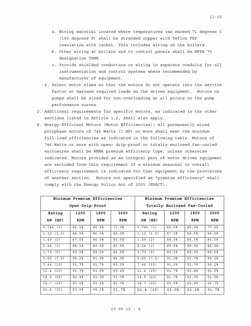
11-10
23 05 12 - 4
a. Wiring material located where temperatures can exceed 71 degrees C
(160 degrees F) shall be stranded copper with Teflon FEP
insulation with jacket. This includes wiring on the boilers.
b. Other wiring at boilers and to control panels shall be NFPA 70
designation THWN.
c. Provide shielded conductors or wiring in separate conduits for all
instrumentation and control systems where recommended by
manufacturer of equipment.
4. Select motor sizes so that the motors do not operate into the service
factor at maximum required loads on the driven equipment. Motors on
pumps shall be sized for non-overloading at all points on the pump
performance curves.
J. Additional requirements for specific motors, as indicated in the other
sections listed in Article 1.2, shall also apply.
K. Energy-Efficient Motors (Motor Efficiencies): All permanently wired
polyphase motors of 746 Watts (1 HP) or more shall meet the minimum
full-load efficiencies as indicated in the following table. Motors of
746 Watts or more with open, drip-proof or totally enclosed fan-cooled
enclosures shall be NEMA premium efficiency type, unless otherwise
indicated. Motors provided as an integral part of motor driven equipment
are excluded from this requirement if a minimum seasonal or overall
efficiency requirement is indicated for that equipment by the provisions
of another section. Motors not specified as “premium efficiency” shall
comply with the Energy Policy Act of 2005 (EPACT).
Minimum Premium Efficiencies
Open Drip-Proof
Minimum Premium Efficiencies
Totally Enclosed Fan-Cooled
Rating
kW (HP)
1200
RPM
1800
RPM
3600
RPM
Rating
kW (HP)
1200
RPM
1800
RPM
3600
RPM
0.746 (1) 82.5% 85.5% 77.0% 0.746 (1) 82.5% 85.5% 77.0%
1.12 (1.5) 86.5% 86.5% 84.0% 1.12 (1.5) 87.5% 86.5% 84.0%
1.49 (2) 87.5% 86.5% 85.5% 1.49 (2) 88.5% 86.5% 85.5%
2.24 (3) 88.5% 89.5% 85.5% 2.24 (3) 89.5% 89.5% 86.5%
3.73 (5) 89.5% 89.5% 86.5% 3.73 (5) 89.5% 89.5% 88.5%
5.60 (7.5) 90.2% 91.0% 88.5% 5.60 (7.5) 91.0% 91.7% 89.5%
7.46 (10) 91.7% 91.7% 89.5% 7.46 (10) 91.0% 91.7% 90.2%
11.2 (15) 91.7% 93.0% 90.2% 11.2 (15) 91.7% 92.4% 91.0%
14.9 (20) 92.4% 93.0% 91.0% 14.9 (20) 91.7% 93.0% 91.0%
18.7 (25) 93.0% 93.6% 91.7% 18.7 (25) 93.0% 93.6% 91.7%
22.4 (30) 93.6% 94.1% 91.7% 22.4 (30) 93.0% 93.6% 91.7%
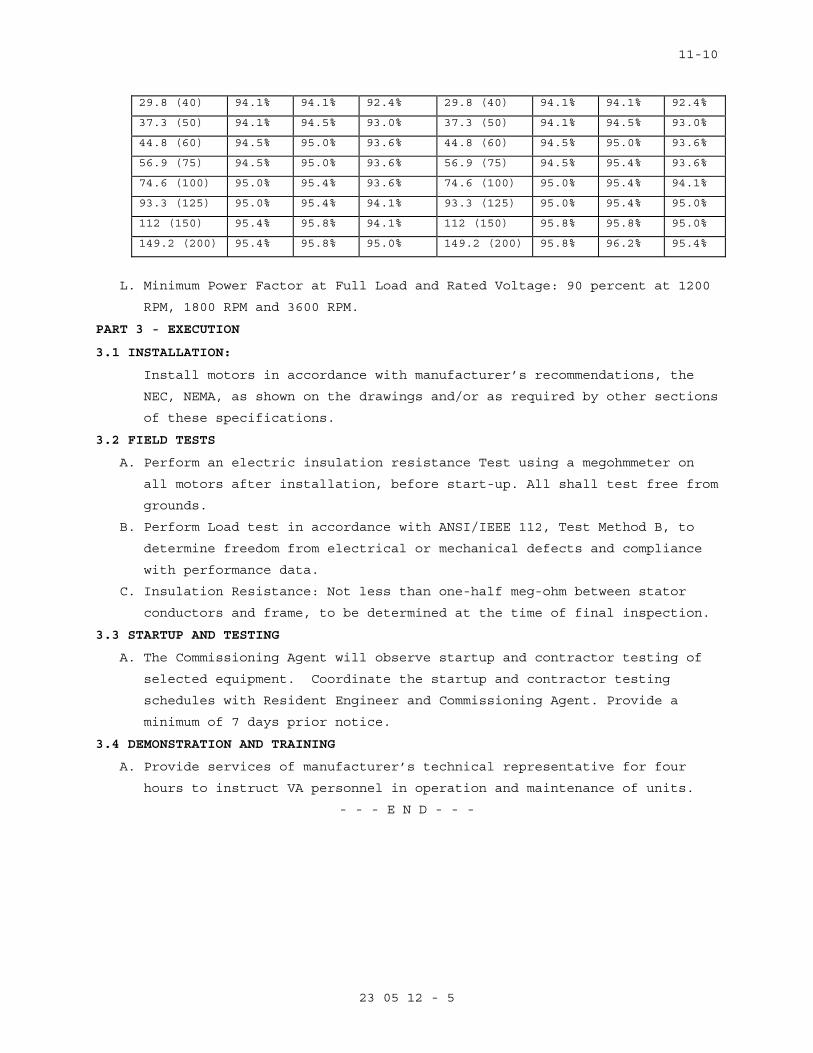
11-10
23 05 12 - 5
29.8 (40) 94.1% 94.1% 92.4% 29.8 (40) 94.1% 94.1% 92.4%
37.3 (50) 94.1% 94.5% 93.0% 37.3 (50) 94.1% 94.5% 93.0%
44.8 (60) 94.5% 95.0% 93.6% 44.8 (60) 94.5% 95.0% 93.6%
56.9 (75) 94.5% 95.0% 93.6% 56.9 (75) 94.5% 95.4% 93.6%
74.6 (100) 95.0% 95.4% 93.6% 74.6 (100) 95.0% 95.4% 94.1%
93.3 (125) 95.0% 95.4% 94.1% 93.3 (125) 95.0% 95.4% 95.0%
112 (150) 95.4% 95.8% 94.1% 112 (150) 95.8% 95.8% 95.0%
149.2 (200) 95.4% 95.8% 95.0% 149.2 (200) 95.8% 96.2% 95.4%
L. Minimum Power Factor at Full Load and Rated Voltage: 90 percent at 1200
RPM, 1800 RPM and 3600 RPM.
PART 3 - EXECUTION
3.1 INSTALLATION:
Install motors in accordance with manufacturer’s recommendations, the
NEC, NEMA, as shown on the drawings and/or as required by other sections
of these specifications.
3.2 FIELD TESTS
A. Perform an electric insulation resistance Test using a megohmmeter on
all motors after installation, before start-up. All shall test free from
grounds.
B. Perform Load test in accordance with ANSI/IEEE 112, Test Method B, to
determine freedom from electrical or mechanical defects and compliance
with performance data.
C. Insulation Resistance: Not less than one-half meg-ohm between stator
conductors and frame, to be determined at the time of final inspection.
3.3 STARTUP AND TESTING
A. The Commissioning Agent will observe startup and contractor testing of
selected equipment. Coordinate the startup and contractor testing
schedules with Resident Engineer and Commissioning Agent. Provide a
minimum of 7 days prior notice.
3.4 DEMONSTRATION AND TRAINING
A. Provide services of manufacturer’s technical representative for four
hours to instruct VA personnel in operation and maintenance of units.
- - - E N D - - -

05-11
23 05 93 - 1
SECTION 23 05 93 TESTING, ADJUSTING, AND BALANCING FOR HVAC
PART 1 - GENERAL
1.1 DESCRIPTION
A. Testing, adjusting, and balancing (TAB) of heating, ventilating and air
conditioning (HVAC) systems. TAB includes the following:
1. Balancing air distribution systems; adjustment of total system to
provide design performance; and testing performance of equipment and
automatic controls.
2. Recording and reporting results.
B. Definitions:
1. Basic TAB used in this Section: Chapter 37, "Testing, Adjusting and
Balancing" of 2007 ASHRAE Handbook, "HVAC Applications".
2. TAB: Testing, Adjusting and Balancing; the process of checking and
adjusting HVAC systems to meet design objectives.
3. AABC: Associated Air Balance Council.
4. NEBB: National Environmental Balancing Bureau.
5. Air Systems: Includes all outside air, supply air, return air,
exhaust air and relief air systems.
6. Flow rate tolerance: The allowable percentage variation, minus to
plus, of actual flow rate from values (design) in the contract
documents.
1.2 RELATED WORK
A. Section 23 05 11, COMMON WORK RESULTS FOR HVAC: General Mechanical
Requirements.
B. Section 23 31 00, HVAC DUCTS AND CASINGS: Duct Leakage.
C. Section 23 09 23, DIRECT-DIGITAL CONTROL SYSTEM FOR HVAC: Controls and
Instrumentation Settings.
D. Section 23 05 12 GENERAL MOTOR REQUIREMENTS FOR HVAC AND STEAM
GENERATION EQUIPMENT
1.3 QUALITY ASSURANCE
A. Refer to Articles, Quality Assurance and Submittals, in Section
23 05 11, COMMON WORK RESULTS FOR HVAC.
B. Qualifications:
1. TAB Agency: The TAB agency shall be a subcontractor of the General
Contractor and shall report to and be paid by the General
Contractor.

05-11
23 05 93 - 2
2. The TAB agency shall be either a certified member of AABC or
certified by the NEBB to perform TAB service for HVAC, water
balancing and vibrations and sound testing of equipment. The
certification shall be maintained for the entire duration of duties
specified herein. If, for any reason, the agency loses subject
certification during this period, the General Contractor shall
immediately notify the Resident Engineer and submit another TAB firm
for approval. Any agency that has been the subject of disciplinary
action by either the AABC or the NEBB within the five years
preceding Contract Award shall not be eligible to perform any work
related to the TAB. All work performed in this Section and in other
related Sections by the TAB agency shall be considered invalid if
the TAB agency loses its certification prior to Contract completion,
and the successor agency’s review shows unsatisfactory work
performed by the predecessor agency.
3. TAB Specialist: The TAB specialist shall be either a member of AABC
or an experienced technician of the Agency certified by NEBB. The
certification shall be maintained for the entire duration of duties
specified herein. If, for any reason, the Specialist loses subject
certification during this period, the General Contractor shall
immediately notify the Resident Engineer and submit another TAB
Specialist for approval. Any individual that has been the subject of
disciplinary action by either the AABC or the NEBB within the five
years preceding Contract Award shall not be eligible to perform any
duties related to the HVAC systems, including TAB. All work
specified in this Section and in other related Sections performed by
the TAB specialist shall be considered invalid if the TAB Specialist
loses its certification prior to Contract completion and must be
performed by an approved successor.
4. TAB Specialist shall be identified by the General Contractor within
60 days after the notice to proceed. The TAB specialist will be
coordinating, scheduling and reporting all TAB work and related
activities and will provide necessary information as required by the
Resident Engineer. The responsibilities would specifically include:
a. Shall directly supervise all TAB work.
b. Shall sign the TAB reports that bear the seal of the TAB
standard. The reports shall be accompanied by report forms and
schematic drawings required by the TAB standard, AABC or NEBB.

05-11
23 05 93 - 3
c. Would follow all TAB work through its satisfactory completion.
d. Shall provide final markings of settings of all HVAC adjustment
devices.
e. Permanently mark location of duct test ports.
5. All TAB technicians performing actual TAB work shall be experienced
and must have done satisfactory work on a minimum of 3 projects
comparable in size and complexity to this project. Qualifications
must be certified by the TAB agency in writing. The lead technician
shall be certified by AABC or NEBB
C. Test Equipment Criteria: The instrumentation shall meet the
accuracy/calibration requirements established by AABC National
Standards or by NEBB Procedural Standards for Testing, Adjusting and
Balancing of Environmental Systems and instrument manufacturer. Provide
calibration history of the instruments to be used for test and balance
purpose.
D. Tab Criteria:
1. One or more of the applicable AABC, NEBB or SMACNA publications,
supplemented by ASHRAE Handbook "HVAC Applications" Chapter 36, and
requirements stated herein shall be the basis for planning,
procedures, and reports.
2. Flow rate tolerance: Following tolerances are allowed. For
tolerances not mentioned herein follow ASHRAE Handbook "HVAC
Applications", Chapter 36, as a guideline. Air Filter resistance
during tests, artificially imposed if necessary, shall be at least
100 percent of manufacturer recommended change over pressure drop
values for pre-filters and after-filters.
a. Air handling unit and all other fans, cubic meters/min (cubic
feet per minute): Minus 0 percent to plus l0 percent.
b. Air terminal units (maximum values): Minus 2 percent to plus l0
percent.
c. Radioisotope hoods/cabinets: 0 percent to plus l0 percent.
d. Minimum outside air: 0 percent to plus 10 percent.
e. Individual room air outlets and inlets, and air flow rates not
mentioned above: Minus 5 percent to plus l0 percent except if the
air to a space is 100 CFM or less the tolerance would be minus 5
to plus 5 percent.
f. Heating hot water pumps and hot water coils: Minus 5 percent to
plus 5 percent.
05-11
23 05 93 - 4
g. Chilled water and condenser water pumps: Minus 0 percent to plus
5 percent.
h. Chilled water coils: Minus 0 percent to plus 5 percent.
3. Systems shall be adjusted for energy efficient operation as
described in PART 3.
4. Typical TAB procedures and results shall be demonstrated to the
Resident Engineer for one air distribution system (including all
fans, three terminal units, three rooms randomly selected by the
Resident Engineer) and one hydronic system (pumps and three coils)
as follows:
a. When field TAB work begins.
b. During each partial final inspection and the final inspection for
the project if requested by VA.
1.4 SUBMITTALS
A. Submit in accordance with Section 01 33 23, SHOP DRAWINGS, PRODUCT
DATA, and SAMPLES.
B. Submit names and qualifications of TAB agency and TAB specialists
within 60 days after the notice to proceed. Submit information on three
recently completed projects and a list of proposed test equipment.
C. For use by the Resident Engineer staff, submit one complete set of
applicable AABC or NEBB publications that will be the basis of TAB
work.
D. Submit Following for Review and Approval:
1. Final TAB reports covering flow balance and adjustments, performance
tests, vibration tests and sound tests.
2. Include in final reports uncorrected installation deficiencies noted
during TAB and applicable explanatory comments on test results that
differ from design requirements.
E. Prior to request for Final or Partial Final inspection, submit
completed Test and Balance report for the area.
1.5 APPLICABLE PUBLICATIONS
A. The following publications form a part of this specification to the
extent indicated by the reference thereto. In text the publications are
referenced to by the acronym of the organization.
05-11
23 05 93 - 5
B. American Society of Heating, Refrigerating and Air Conditioning
Engineers, Inc. (ASHRAE):
2007 ...................HVAC Applications ASHRAE Handbook, Chapter 37,
Testing, Adjusting, and Balancing and Chapter
47, Sound and Vibration Control
C. Associated Air Balance Council (AABC):
2002....................AABC National Standards for Total System
Balance
D. National Environmental Balancing Bureau (NEBB):
7th Edition 2005 ........Procedural Standards for Testing, Adjusting,
Balancing of Environmental Systems
2nd Edition 2006 .......Procedural Standards for the Measurement of
Sound and Vibration
3rd Edition 2009 ........Procedural Standards for Whole Building Systems
Commissioning of New Construction
E. Sheet Metal and Air Conditioning Contractors National Association
(SMACNA):
3rd Edition 2002 ........HVAC SYSTEMS Testing, Adjusting and Balancing
PART 2 - PRODUCTS
2.1 PLUGS
Provide plastic plugs to seal holes drilled in ductwork for test
purposes.
PART 3 - EXECUTION
3.1 GENERAL
A. Refer to TAB Criteria in Article, Quality Assurance.
B. Obtain applicable contract documents and copies of approved submittals
for HVAC equipment and automatic control systems.
3.2 TAB REPORTS
A. The TAB contractor shall provide raw data immediately in writing to the
Resident Engineer if there is a problem in achieving intended results
before submitting a formal report.
B. If over 20 percent of readings in the intermediate report fall outside
the acceptable range, the TAB report shall be considered invalid and
all contract TAB work shall be repeated and re-submitted for approval
at no additional cost to the owner.
C. Do not proceed with the remaining systems until intermediate report is
approved by the Resident Engineer.
05-11
23 05 93 - 6
3.3 TAB PROCEDURES
A. Tab shall be performed in accordance with the requirement of the
Standard under which TAB agency is certified by either AABC or NEBB.
B. General: During TAB all related system components shall be in full
operation. Fan and pump rotation, motor loads and equipment vibration
shall be checked and corrected as necessary before proceeding with TAB.
Set controls and/or block off parts of distribution systems to simulate
design operation of variable volume air or water systems for test and
balance work.
C. Coordinate TAB procedures with existing systems and any phased
construction completion requirements for the project.
D. Allow 2 days time in construction schedule for TAB and submission of
all reports for an organized and timely correction of deficiencies.
E. Air Balance and Equipment Test: Include fans, terminal units, room
diffusers/outlets/inlets, and laboratory radioisotope hoods.
1. Artificially load air filters by partial blanking to produce air
pressure drop of manufacturer’s recommended pressure drop.
2. Adjust fan speeds to provide design air flow. V-belt drives,
including fixed pitch pulley requirements, are specified in Section
23 05 11, COMMON WORK RESULTS FOR HVAC.
3. Test and balance systems in all specified modes of operation,
including variable volume, economizer, and fire emergency modes.
Verify that dampers and other controls function properly.
4. Variable air volume (VAV) systems:
a. Coordinate TAB, including system volumetric controls, with
Section 23 09 23, DIRECT-DIGITAL CONTROL SYSTEM FOR HVAC.
b. Adjust operating pressure control setpoint to maintain the design
flow to each space with the lowest setpoint.
5. Record final measurements for air handling equipment performance
data sheets.
3.4 MARKING OF SETTINGS
Following approval of Tab final Report, the setting of all HVAC
adjustment devices including valves, splitters and dampers shall be
permanently marked by the TAB Specialist so that adjustment can be
restored if disturbed at any time. Style and colors used for markings
shall be coordinated with the Resident Engineer.

05-11
23 05 93 - 7
3.5 IDENTIFICATION OF TEST PORTS
The TAB Specialist shall permanently and legibly identify the location
points of duct test ports. If the ductwork has exterior insulation, the
identification shall be made on the exterior side of the insulation.
All penetrations through ductwork and ductwork insulation shall be
sealed to prevent air leaks and maintain integrity of vapor barrier.
3.6 PHASING
A. Phased Projects: Testing and Balancing Work to follow project with
areas shall be completed per the project phasing. Upon completion of
the project all areas shall have been tested and balanced per the
contract documents.
B. Existing Areas: Systems that serve areas outside of the project scope
shall not be adversely affected. Measure existing parameters where
shown to document system capacity.
- - E N D - - -

23 09 23 - 1
SECTION 23 09 23.13 20
DIRECT DIGITAL CONTROL SYSTEMS FOR HVAC
PART 1 - GENERAL
1.1 REFERENCES
A. The publications listed below form a part of this specification to the
extent referenced. The publications are referred to in the text by the
basic designation only.
B. AIR MOVEMENT AND CONTROL ASSOCIATION INTERNATIONAL (AMCA)
AMCA 500-D (1998) Laboratory Methods of Testing Dampers for Rating
C. AMERICAN NATIONAL STANDARDS INSTITUTE (ANSI)
ANSI/ATA 878.1 (1999) ARCNET - Local Area Network: Token Ring
D. AMERICAN SOCIETY OF HEATING, REFRIGERATING AND AIR-CONDITIONING
ENGINEERS(ASHRAE)
ASHRAE 135 (2004; Interpretations 1 thru 18; Addenda A 2004; Errata
2005; Addenda C 2006; Addenda D 2006; Errata to Addenda D 2006; Addenda
F 2007; Addenda E 2007; Errata 2007)
E. ASME INTERNATIONAL (ASME)
ASME B16.18 (2001; R 2005) Cast Copper Alloy Solder Joint Pressure
Fittings
ASME B16.22 (2001; R 2005) Standard for Wrought Copper and Copper Alloy
Solder Joint Pressure Fittings
ASME B16.26 (2006) Standard for Cast Copper Alloy Fittings for Flared
Copper Tubes
ASME B16.34 (2004) Valves - Flanged, Threaded and Welding End
ASME B16.5 (2003) Standard for Pipe Flanges and Flanged Fittings: NPS
1/2 Through NPS 24
ASME B31.1 (2007) Power Piping
ASME B40.100 (2006) Pressure Gauges and Gauge Attachments
ASME BPVC (2007) Boiler and Pressure Vessel Codes
F. ASTM INTERNATIONAL (ASTM)
ASTM A 126 (2004) Standard Specification for Gray Iron Castings for
Valves, Flanges, and Pipe Fittings
ASTM B 117 (2007) Standing Practice for Operating Salt Spray (Fog)
Apparatus
ASTM B 32 (2004) Standard Specification for Solder Metal
ASTM B 75 (2002) Standard Specification for Seamless Copper Tube
ASTM B 88 (2003) Standard Specification for Seamless Copper Water Tube
23 09 23 - 2
ASTM B 88M (2005) Standard Specification for Seamless Copper Water Tube
(Metric)
ASTM D 1238 (2004c) Melt Flow Rates of Thermoplastics by Extrusion
Plastometer
ASTM D 1693 (2007a) Standard Test Method for Environmental Stress-
Cracking of Ethylene Plastics
ASTM D 635 (2006) Standard Test Method for Rate of Burning and/or
Extent and Time of Burning of Self-Supporting Plastics in a Horizontal
Position
ASTM D 638 (2003) Standard Test Method for Tensile Properties of
Plastics
ASTM D 792 (2000) Density and Specific Gravity (Relative Density) of
Plastics by Displacement
G. INSTITUTE OF ELECTRICAL AND ELECTRONICS ENGINEERS (IEEE)
IEEE C57.13 (1993; R 2003) Standard Requirements for Instrument
Transformers
IEEE C62.41.1 (2002) IEEE Guide on the Surges Environment in Low-
Voltage (1000 V and Less) AC Power Circuits
IEEE C62.41.2 (2002) IEEE Recommended Practice on Characterization of
Surges in Low-Voltage (1000 V and Less) AC Power Circuits
IEEE C62.45 (2002) Surge Testing for Equipment Connected to Low-Voltage
(1000v and less)AC Power Circuits
H. INTERNATIONAL ORGANIZATION FOR STANDARDIZATION (ISO)
ISO/IEC 8802 (2000) Telecommunications and Information Exchange Between
Systems
I. NATIONAL FIRE PROTECTION ASSOCIATION (NFPA)
NFPA 70 (2007) National Electrical Code – 2008 Edition
NFPA 72 (2006) National Fire Alarm Code
NFPA 90A (2002; Errata 2003; Errata 2005) Standard for the Installation
of Air Conditioning and Ventilating Systems
J. NATIONAL FLUID POWER ASSOCIATION (NFLPA)
NFLPA C12.10 (2004) Watthour Meters SHEET METAL AND AIR CONDITIONING
K. CONTRACTORS' NATIONAL ASSOCIATION (SMACNA)
SMACNA HVAC Duct Const Stds (1995; Addendum 1997, 2nd Ed) HVAC Duct
Construction Standards - Metal and Flexible
L. UNDERWRITERS LABORATORIES (UL)
UL 1449 (2006) Surge Protective Devices
UL 506 (2000; Rev thru May 2006) Standard for Specialty Transformers

23 09 23 - 3
UL 508A (2001; Rev thru Dec 2007) Standard for Industrial Control
Panels
UL 916 (2007) Energy Management Equipment
1.2 RELATED WORK:
A. Section 26 05 11, REQUIREMENTS FOR ELECTRICAL INSTALLATIONS: General
electrical requirements common to more than one Section of Division 26.
B. Section 26 29 11, LOW-VOLTAGE MOTOR STARTERS: Starters, control and
protection for motors.
C. Section 23 05 11, COMMON WORK RESULTS FOR HVAC.
D. Fume Hoods: Section 11 53 13, LABORATORY FUME HOODS.
E. Testing and Balancing of Air Flows: Section 23 05 93, TESTING,
F. Section 23 31 00, HVAC DUCTS AND CASINGS.
1.3 DEFINITIONS
A. BAS
1. Building Automation Systems, including DDC (Direct Digital Controls)
used for facility automation and energy management.
B. BAS Owner
1. The regional or local user responsible for managing all aspects of
the BAS operation, including: network connections, workstation
management, submittal review, technical support, control parameters,
and daily operation.
C. Bridge
1. Network hardware that connects two or more network segments at the
physical and data link layers. A bridge may also filter messages.
D. Broadcast
1. A message sent to all devices on a network segment.
E. Device
1. Any control system component, usually a digital controller.
F. Digital Controller
1. An electronic controller, usually with internal programming logic
and digital and analog input/output capability, which performs
control functions.
G. Direct Digital Control (DDC)
1. Digital controllers performing control logic. Usually the controller
directly senses physical values, makes control decisions with
internal programs, and outputs control signals to directly operate
switches, valves, dampers, and motor controllers.
H. DDC System

23 09 23 - 4
1. A network of digital controllers, communication architecture, and
user interfaces. A DDC system may include programming, sensors,
actuators, switches, relays, factory controls, operator
workstations, and various other devices, components, and attributes.
I. Ethernet
1. A family of local-area-network technologies providing high-speed
networking features over various media.
J. Firmware
1. Software programmed into read only memory (ROM), flash memory,
electrically erasable programmable read only memory (EEPROM), or
erasable programmable read only memory (EPROM) chips.
K. Gateway
1. Communication hardware connecting two or more different protocols,
similar to human language translators. The Gateway translates one
protocol into equivalent concepts for the other protocol.
L. Half Router
1. A device that participates as one partner in a BACnet point-to-point
(PTP) connection. Two half-routers in an active PTP connection
combine to form a single router.
M. Hub
1. A common connection point for devices on a network.
N. Internet Protocol (IP, TCP/IP, UDP/IP)
1. A communication method, the most common use is the World Wide Web.
At the lowest level, it is based on Internet Protocol (IP), a method
for conveying and routing packets of information over various LAN
media. Two common protocols using IP are User Datagram Protocol
(UDP) and Transmission Control Protocol (TCP). UDP conveys
information to well-known "sockets" without confirmation of receipt.
TCP establishes "sessions", which have end-to-end confirmation and
guaranteed sequence of delivery.
O. Input/Output (I/O)
1. Physical inputs and outputs to and from a device, although the term
sometimes describes software, or "virtual" I/O. See also "Points".
P. I/O Expansion Unit
1. An I/O expansion unit provides additional point capacity to a
digital controller.
Q. IP subnet
1. Internet protocol (IP) identifies individual devices with a 32-bit
number divided into four groups from 0 to 255. Devices are often

23 09 23 - 5
grouped and share some portion of this number. For example, one
device has IP address 209.185.47.68 and another device has IP
address 209.185.47.82. These two devices share Class C subnet
209.185.47.00
R. Local-Area Network (LAN)
1. A communication network that spans a limited geographic area and
uses the same basic communication technology throughout.
S. Network
1. Communication technology for data communications.
T. Network Number
1. A site-specific number assigned to each network segment to identify
for routing.
U. Peer-to-Peer
1. Peer-to-peer refers to devices where any device can initiate and
respond to communication with other devices.
V. Performance Verification Test (PVT)
1. The procedure for determining if the installed BAS meets design
criteria prior to final acceptance. The PVT is performed after
installation, testing, and balancing of mechanical systems.
Typically the PVT is performed by the Contractor in the presence of
the Government.
W. PID
1. Proportional, integral, and derivative control; three parameters
used to control modulating equipment to maintain a setpoint.
Derivative control is often not required for HVAC systems (leaving
"PI" control).
X. Points
1. Physical and virtual inputs and outputs. See also "Input/Output".
Y. Stand-Alone Control
1. Refers to devices performing equipment-specific and small system
control without communication to other devices or computers for
physical I/O, excluding outside air and other common shared
conditions. Devices are located near controlled equipment, with
physical input and output points limited to 64 or less per device,
except for complex individual equipment or systems. Failure of any
single device will not cause other network devices to fail.
1.4 DIRECT DIGITAL CONTROL SYSTEMS FOR HVAC DESCRIPTION
A. Provide a Siemens Lab Apogee DDC system. including associated equipment
and accessories. All new devices are accessible without the use of

23 09 23 - 6
gateways, unless gateways are shown on the design drawings and
specifically requested.
B. The existing server and operator workstations are located at the
Pensacola VA Facility.
1. Design Requirements
a. Control System Drawings Title Sheet - Provide a title sheet for
the control system drawing set. Include the project title,
project location, contract number, the controls contractor
preparing the drawings, an index of the control drawings in the
set, and a legend of the symbols and abbreviations used
throughout the control system drawings.
b. List of I/O Points - Also known as a Point Schedule, provide for
each input and output point physically connected to a digital
controller: point name, point description, point type (Analog
Output (AO), Analog Input (AI), Binary Output (BO), Binary Input
(BI)), point sensor range, point actuator range, point address,
and point connection terminal number. Typical schedules for
multiple identical equipment are allowed unless otherwise
requested in design or contract criteria.
c. Control System Components List - Provide a complete list of
control system components installed on this project. Include for
each controller and device: control system schematic name,
control system schematic designation, device description,
manufacturer, and manufacturer part number. For sensors, include
point name, sensor range, and operating limits. For valves,
include body style, Cv, design flow rate, pressure drop, valve
characteristic (linear or equal percentage), and pipe connection
size. For actuators, include point name, spring or non-spring
return, modulating or two-position action, normal (power fail)
position, nominal control signal operating range (0-10 volts DC
or 4-20 milliamps), and operating limits.
d. Control System Schematics - Provide control system schematics.
Typical schematics for multiple identical equipment are allowed
unless otherwise requested in design or contract criteria.
Include the following:
1) Location of each input and output device
2) Flow diagram for each piece of HVAC equipment
3) Name or symbol for each control system component, such as V-1
for a valve

23 09 23 - 7
4) Setpoints, with differential or proportional band values
5) Written sequence of operation for the HVAC equipment
6) Valve and Damper Schedules, with normal (power fail) position
e. HVAC Equipment Electrical Ladder Diagrams - Provide HVAC
equipment electrical ladder diagrams. Indicate required
electrical interlocks.
f. Component Wiring Diagrams - Provide a wiring diagram for each
type of input device and output device. Indicate how each device
is wired and powered; showing typical connections at the digital
controller and power supply. Show for all field connected devices
such as control relays, motor starters, actuators, sensors, and
transmitters.
g. Terminal Strip Diagrams - Provide a diagram of each terminal
strip. Indicate the terminal strip location, termination numbers,
and associated point names.
h. Communication Architecture Schematic - Provide a schematic
showing the project's entire communication network, including
addressing used for LANs, LAN devices including routers and
bridges, gateways, controllers, workstations, and field interface
devices. If applicable, show connection to existing networks.
1.5 SUBMITTALS
A. Submit detailed and annotated manufacturer's data, drawings, and
specification sheets for each item listed, that clearly show compliance
with the project specifications.
1.6 QUALITY ASSURANCE
A. Standard Products - Provide material and equipment that are standard
manufacturer's products currently in production and supported by a
local service organization.
B. Delivery, Storage, and Handling - Handle, store, and protect equipment
and materials to prevent damage before and during installation
according to manufacturer's recommendations, and as approved by the
Contracting Officer. Replace damaged or defective items.
C. Operating Environment - Protect components from humidity and
temperature variation, dust, and contaminants. If components are stored
before installation, keep them within the manufacturer's limits.
D. Finish of New Equipment - New equipment finishing shall be factory
provided. Manufacturer's standard factory finishing shall be proven to
withstand 125 hours in a salt-spray fog test. Equipment located
outdoors shall be proven to withstand 500 hours in a salt-spray fog

23 09 23 - 8
test. Salt-spray fog test shall be according to ASTM B 117, with
acceptance criteria as follows: immediately after completion of the
test, the finish shall show no signs of degradation or loss of adhesion
beyond 0.125 inch on either side of the scratch mark.
E. Verification of Dimensions - The contractor shall verify all dimensions
in the field, and advise the Contracting Officer of any discrepancy
before performing work.
F. Contractor's Qualifications - Submit documentation certifying the
controls Contractor performing the work has completed at least three
DDC systems installations of a similar design to this project, and
programmed similar sequences of operation for at least two years.
G. Modification of References - The advisory provisions in ASME B31.1 and
NFPA 70 are mandatory. Substitute "shall" for "should" wherever it
appears and interpret all references to the "authority having
jurisdiction" and "owner" to mean the Contracting Officer.
PART 2 - PRODUCTS
2.1 DDC SYSTEM
A. The Laboratory Control System (LCS) shall be fully integrated to the
existing Siemens HVAC Instrumentation and Controls System to maintain
laboratory room supply and exhaust airflows, room pressurization, room
ambient temperature and the laboratory exhaust system functionality as
specified herein
1. The LCS shall include all new laboratory room supply airflow
terminals, reheat coils, reheat coil valves, air terminal actuators,
sensors, associated instrumentation and the control units and
associated interconnecting wiring and pneumatic tubing as described
on plans. Any and all associated components required to implement a
fully functioning and integrated system as specified herein shall
also be provided. System verification and other documentation as
specified under the Sections referenced herein shall also be
included.
2. All LCS data shall be capable of being accessed by authorized
persons via the facility's Siemens HVAC control system.
3. APPROVED LABORATORY CONTROL SYSTEM MANUFACTURERS
The following is the approved LCS manufacturer and product line:
Manufacturer Product Line
Siemens Industry, Building Technologies Apogee System
B. LABORATORY CONTROLLERS
1. CONSTANT VOLUME FUME HOOD MONITOR

23 09 23 - 9
a. Furnish and install a UL 916 listed individual constant volume
fume hood monitor for each fume hood which shall display the
required average face velocity. Documentation verifying the UL
916 Listing for the fume hood monitor shall be included in any
proposal as well as the submittal.
b. The fume hood monitor shall also interface to an Operator Display
Panel (ODP) at the designated measurement location on the front
of the fume hood as shown on the project plans. The ODP shall
provide a continuous digital display of average fume hood face
velocity. The fume hood face velocity display shall be the true
average face velocity as calculated by the fume hood monitor
based upon actual measured fume hood exhaust differential
pressure.
c. The ODP shall also include separate colored pilot lights that
shall illuminate to indicate fume hood operational status as:
1) Green indicating normal operation.
2) Red indicating alarm condition or OFF.
d. The ODP shall sound an audible alarm device in response to face
velocity alarm conditions and the ODP digital display shall
change to "LOW FACE VELOCITY" or "HIGH FACE VELOCITY" appropriate
to the alarm condition. A SILENCE pushbutton on the ODP shall
allow the user to silence the audible alarm which shall then
remain silent until a subsequent alarm occurs.
e. All fume hood control and ODP display and operational parameters
shall be established and be changeable only by authorized
personnel using a portable operator's terminal. These operational
parameters shall include:
1) Face velocity high and low alarm limits and associated alarm
time delay to avoid transient alarms.
2) Face velocity high and low warning limits.
f. A portable operator's terminal shall plug into the ODP as well as
into the laboratory room controller. In addition, all laboratory
fume hood and laboratory room control parameters along with all
other facility control and monitoring functions shall be
accessible to authorized personnel from designated terminals on
the BAS control and monitoring network.
g. Momentary or extended losses of power shall not change or affect
any CV fume hood monitoring setpoints, operational parameters or
stored data. Upon resumption of power after a power failure, fume

23 09 23 - 10
hood monitors shall resume full normal operation exactly as
before the power failure and without any need for manual
intervention.
2. CONTROLLERS FOR CONSTANT VOLUME TERMINALS
a. All CV terminal control applications shall be field-selectable
such that a single controller may be used in conjunction with
other types of terminal units to perform the specified sequences
of control. Application Specific Controllers (ASCs) that require
factory application changes are not acceptable. The CV terminal
ASC shall support CV with hot water reheat
b. The controller shall include a differential pressure transducer
that shall connect to the terminal unit manufacturer's standard
averaging air velocity sensor to measure the average differential
pressure in the duct. The controller shall convert this value to
actual airflow. Single point air velocity sensing is not
acceptable. The differential pressure transducer shall have a
measurement range of 0 to 4000 fpm (0 to 20.4 m/s) and
measurement accuracy of +5% at 400 to 4000 fpm (2 to 20 m/s),
insuring primary airflow conditions shall be controlled and
maintained to within +5% of setpoint at the specified parameters.
The BMS contractor shall provide the velocity sensor if required
to meet the specified functionality.
C. Direct Digital Controllers
1. Direct digital controllers shall be UL 916 rated.
a. I/O Point Limitation
The total number of I/O hardware points used by a single stand-
alone digital controller, including I/O expansion units, shall
not exceed 64, except for complex individual equipment or
systems. Place I/O expansion units in the same cabinet as the
digital controller.
b. Environmental Limits
Controllers shall be suitable for, or placed in protective
enclosures suitable for the environment (temperature, humidity,
dust, and vibration) where they are located.
c. Stand-Alone Control
Provide stand-alone digital controllers.
d. Internal Clock
Provide internal clocks for all Building Controllers .
Automatically synchronize system clocks daily from an operator-

23 09 23 - 11
designated controller. The system shall automatically adjust for
daylight saving time.
e. Memory
Provide sufficient memory for each controller to support the
required control, communication, trends, alarms, and messages.
Protect programs residing in memory with EEPROM, flash memory, or
by an uninterruptible power source (battery or uninterruptible
power supply). The backup power source shall have capacity to
maintain the memory during a 72-hour continuous power outage.
Rechargeable power sources shall be constantly charged while the
controller is operating under normal line power. Batteries shall
be replaceable without soldering. Trend and alarm history
collected during normal operation shall not be lost during power
outages less than 72 hours long.
f. Immunity to Power Fluctuations
Controllers shall operate at 90% to 110% nominal voltage rating.
g. Transformer
The controller power supply shall be fused or current limiting
and rated at 125% power consumption.
h. Wiring Terminations
Use screw terminal wiring terminations for all field-installed
controllers. Provide field-removable modular terminal strip or a
termination card connected by a ribbon cable for all controllers
other than terminal units.
i. Input and Output Interface
Provide hard-wired input and output interface for all controllers
as follows:
1) Protection: Shorting an input or output point to itself, to
another point, or to ground shall cause no controller damage.
Input or output point contact with sources up to 24 volts AC
or DC for any duration shall cause no controller damage.
2) Binary Inputs: Binary inputs shall have a toggle switch and
monitor on and off contacts from a "dry" remote device without
external power, and external 5-24 VDC voltage inputs.
3) Pulse Accumulation Inputs: Pulse accumulation inputs shall
conform to binary input requirements and accumulate pulses at
a resolution suitable to the application.
23 09 23 - 12
4) Analog Inputs: Analog inputs shall monitor low-voltage (0-10
VDC), current (4-20 mA), or resistance (thermistor or RTD)
signals.
5) Binary Outputs: Binary outputs shall have a toggle switch and
send a pulsed 24 VDC low-voltage signal for modulation
control, or provide a maintained open-closed position for on-
off control. For HVAC equipment and plant controllers, provide
for manual overrides, either with three-position (on-off-auto)
override switches and status lights, or with an adjacent
operator display and interface. Where appropriate, provide a
method to select normally open or normally closed operation.
j. Analog Outputs: Analog outputs shall send modulating 0-10 VDC or
4-20 mA signals to control output devices.
k. Tri-State Outputs: Tri-State outputs shall provide three-point
floating control of terminal unit electronic actuators.
l. Communications Ports
1) Direct-Connect Interface Ports: Provide at least one extra
communication port at each local panel for direct connecting a
notebook computer or hand-held terminal so all network objects
and properties may be viewed and edited by the operator.
2) Telecommunications Interface Port: Provide one
telecommunication port per building, permitting remote
communication via point-to-point (PTP) protocol over telephone
lines.
m. Digital Controller Cabinet
Provide each digital controller in a factory fabricated cabinet
enclosure. Cabinets located indoors shall protect against dust
and have a minimum NEMA 1 rating, except where indicated
otherwise. Cabinets located outdoors or in damp environments
shall protect against all outdoor conditions and have a minimum
NEMA 4 rating. Outdoor control panels and controllers must be
able to withstand extreme ambient conditions, without malfunction
or failure, whether or not the controlled equipment is running.
If necessary, provide a thermostatically controlled panel heater
in freezing locations, and an internal ventilating fan in
locations exposed to direct sunlight. Cabinets shall have a
hinged lockable door and an offset removable metal back plate,
except controllers integral with terminal units, like those
mounted on VAV boxes. Provide like-keyed locks for all hinged
23 09 23 - 13
panels provided and a set of two keys at each panel, with one key
inserted in the lock.
n. Main Power Switch and Receptacle
Provide each control cabinet with a main external power on/off
switch located inside the cabinet. Also provide each cabinet with a
separate 120 VAC duplex receptacle.
D. DDC Software
1. Programming
Provide programming to execute the sequence of operation indicated.
Provide all programming and tools to configure and program all
controllers. Provide programming routines in simple, easy-to-follow
logic with detailed text comments describing what the logic does and
how it corresponds to the project's written sequence of operation.
a. Graphic-based programming shall use a library of function blocks
made from pre-programmed code designed for BAS control. Function
blocks shall be assembled with interconnecting lines, depicting
the control sequence in a flowchart. If providing a computer with
device programming tools as part of the project, graphic programs
shall be viewable in real time showing present values and logical
results from each function block.
b. Menu-based programming shall be done by entering parameters,
definitions, conditions, requirements, and constraints.
c. For line-by-line and text-based programming, declare variable
types (local, global, real, integer, etc.) at the beginning of
the program. Use descriptive comments frequently to describe the
programming.
d. If providing a computer with device programming tools as part of
the project, provide a means for detecting program errors and
testing software strategies with a simulation tool. Simulation
may be inherent within the programming software suite, or
provided by physical controllers mounted in a NEMA 1 test
enclosure. The test enclosure shall contain one dedicated
controller of each type provided under this contract, complete
with power supply and relevant accessories.
2. Parameter Modification
All writeable properties, and all other programming parameters
needed to comply with the project specification shall be adjustable
for devices at any network level, including those accessible with

23 09 23 - 14
web-browser communication, and regardless of programming methods
used to create the applications.
3. Short Cycling Prevention
Provide setpoint differentials and minimum on/off times to prevent
equipment short cycling.
4. Equipment Status Delay
Provide an adjustable delay from when equipment is commanded on or
off and when the control program looks to the status input for
confirmation.
5. Run Time Accumulation
Use the Elapsed Time Property to provide re-settable run time
accumulation for each Binary Output Object connected to mechanical
loads greater than 1 HP, electrical loads greater than 10 KW, or
wherever else specified.
6. Timed Local Override
Provide an adjustable override time for each push of a timed local
override button.
7. Time Synchronization
Provide time synchronization, including adjustments for leap years,
daylight saving time, and operator time adjustments.
8. Scheduling
Provide operating schedules as indicated, with equipment assigned to
groups. Changing the schedule of a group shall change the operating
schedule of all equipment in the group. Groups shall be capable of
operator creation, modification, and deletion. Provide capability to
view and modify schedules in a seven-day week format. Provide
capability to enter holiday and override schedules one full year at
a time.
9. Alarms and Events
Alarms and events shall be capable of having programmed time delays
and high-low limits. When a computer workstation or web server is
connected to the internetwork, alarms/events shall report to the
computer, printer, as defined by an authorized operator. Otherwise
alarms/events shall be stored within a device on the network until
connected to a user interface device and retrieved. Provide
alarms/events in agreement with the point schedule, sequence of
operation, and the BAS Owner. At a minimum, provide programming to
initiate alarms/events any time a piece of equipment fails to
operate, a control point is outside normal range or condition shown

23 09 23 - 15
on schedules, communication to a device is lost, a device has
failed, or a controller has lost its memory.
10. Trending
Provide trend services capable of trending all object present values
set points, and other parameters indicated for trending on project
schedules. Trends may be associated into groups, and a trend report
may be set up for each group. Trends are stored within a device on
the network, with operator selectable trend intervals from 15
seconds up to 60 minutes. The minimum number of consecutive trend
values stored at one time shall be 100 per variable. When trend
memory is full, the most recent data shall overwrite the oldest
data. The operator workstation shall upload trends automatically
upon reaching 3/4 of the device buffer limit , by operator request,
or by time schedule for archiving. Archived and real-time trend data
shall be available for viewing numerically and graphically for at
the workstation.
11. Device Diagnostics
Each controller shall have diagnostic LEDs for power, communication,
and device fault condition. The DDC system shall recognize and
report a non-responsive controller.
12. Power Loss
Upon restoration of power, the DDC system shall perform an orderly
restart and restoration of control.
2.2 SENSORS AND INPUT HARDWARE
Coordinate sensor types with the BAS Owner to keep them consistent with
existing installations.
A. Field-Installed Temperature Sensors
Where feasible, provide the same sensor type throughout the project.
Avoid using transmitters unless absolutely necessary.
1. Thermistors
Precision thermistors may be used in applications below 200 degrees
F. Sensor accuracy over the application range shall be 0.36 degree F
or less between 32 to 150 degrees F. Stability error of the
thermistor over five years shall not exceed 0.25 degree F
cumulative. A/D conversion resolution error shall be kept to 0.1
degree F. Total error for a thermistor circuit shall not exceed 0.5
degree F.
2. Resistance Temperature Detectors (RTDs)
23 09 23 - 16
Provide RTD sensors with platinum elements compatible with the
digital controllers. Encapsulate sensors in epoxy, series 300
stainless steel, anodized aluminum, or copper. Temperature sensor
accuracy shall be 0.1 percent (1 ohm) of expected ohms (1000 ohms)
at 32 degrees F. Temperature sensor stability error over five years
shall not exceed 0.25 degree F cumulative. Direct connection of RTDs
to digital controllers without transmitters is preferred. When RTDs
are connected directly, lead resistance error shall be less than
0.25 degrees F. The total error for a RTD circuit shall not exceed
0.5 degree F.
3. Temperature Sensor Details
a. Room Type: Provide the sensing element components within a
decorative protective cover suitable for surrounding decor.
[Provide room temperature sensors with timed override button,
setpoint adjustment lever, digital temperature display.] [Provide
a communication port or 802.11x wireless support for a portable
operator interface like a notebook computer or PDA.]
b. Duct Probe Type: Ensure the probe is long enough to properly
sense the air stream temperature.
c. Duct Averaging Type: Continuous averaging sensors shall be one
foot in length for each 4 square feet of duct cross-sectional
area, and a minimum length of 6 ft.
d. Pipe Immersion Type: Provide minimum three-inch immersion.
Provide each sensor with a corresponding pipe-mounted sensor
well, unless indicated otherwise. Sensor wells shall be stainless
steel when used in steel piping, and brass when used in copper
piping. Provide the sensor well with a heat-sensitive transfer
agent between the sensor and the well interior.
e. Outside Air Type: Provide the sensing element on the building's
north side with a protective weather shade that positions the
sensor approximately 3 inches off the wall surface, does not
inhibit free air flow across the sensing element, and protects
the sensor from snow, ice, and rain.
B. Transmitters
Provide transmitters with 4 to 20 mA or 0 to 10 VDC linear output
scaled to the sensed input. Transmitters shall be matched to the
respective sensor, factory calibrated, and sealed. Size transmitters
for an output near 50 percent of its full-scale range at normal
operating conditions. The total transmitter error shall not exceed 0.1
23 09 23 - 17
percent at any point across the measured span. Supply voltage shall be
12 to 24 volts AC or DC. Transmitters shall have non-interactive offset
and span adjustments. For temperature sensing, transmitter drift shall
not exceed 0.03 degrees F a year.
1. Relative Humidity Transmitters
Provide transmitters with an accuracy equal to plus or minus 3
percent from 0 to 90% scale, and less than one percent drift per
year. Sensing elements shall be the polymer type.
2. Pressure Transmitters
Provide transmitters integral with the pressure transducer.
C. Current Transducers
Provide current switches as shown on design drawings or point tables.
D. Pneumatic to Electric Transducers
Pneumatic to electronic transducers shall convert a 0 to 20 psig signal
to a proportional 4 to 20 mA or 0 to 10 VDC signal (operator
scaleable). Supply voltage shall be 24 VDC. Accuracy and linearity
shall be 1.0 percent or better.
E. Air Quality Sensors
Provide power supply for each sensor.
1. CO2 Sensors
Provide photo-acoustic type CO2 sensors with integral transducers
where shown and linear output. The devices shall read CO2
concentrations between 0 and 2000 ppm with full scale accuracy of at
least plus or minus 100 ppm.
2. Air Quality Sensors
Provide full spectrum air quality sensors using a hot wire element
based on the Taguchi principle where shown. The sensor shall monitor
a wide range of gaseous volatile organic components common in indoor
air contaminants like paint fumes, solvents, cigarette smoke, and
vehicle exhaust. The sensor shall automatically compensate for
temperature and humidity, have span and calibration potentiometers,
operate on 24 VDC power with output of 0-10 VDC, and have a service
rating of 32 to 140 degrees F and 5 to 95 percent relative humidity.
F. Input Switches
1. Timed Local Overrides
Provide buttons or switches to override the DDC occupancy schedule
programming for each major building zone during unoccupied periods,
and to return HVAC equipment to the occupied mode. This requirement
23 09 23 - 18
is waived for zones clearly intended for 24 hour continuous
operation.
2. Freeze Protection Thermostats
Provide special purpose thermostats with flexible capillary elements
20 feet minimum length for coil face areas up to 40 square feet.
Provide longer elements for larger coils at 1-foot of element for
every 4 square feet of coil face area, or provide additional
thermostats. Provide switch contacts rated for the respective motor
starter's control circuit voltage. Include auxiliary contacts for
the switch's status condition. A freezing condition at any 18-inch
increment along the sensing element's length shall activate the
switch. The thermostat shall be equipped with a manual push-button
reset switch so that when tripped, the thermostat requires manual
resetting before the HVAC equipment can restart.
G. Control Valves
1. Valve Assembly
Valve bodies shall be designed for 125 psig minimum working pressure
or 150 percent of the operating pressure, whichever is greater.
Valve stems shall be Type 316 stainless steel. Valve leakage ratings
shall be 0.01 percent of rated Cv value. Class 125 copper alloy
valve bodies and Class 150 steel or stainless steel valves shall
meet the requirements of ASME B16.5. Cast iron valve components
shall meet the requirements of ASTM A 126 Class B or C.
2. Butterfly Valves
Butterfly valves shall be the threaded lug type suitable for dead-
end service and for modulation to the fully-closed position, with
stainless steel shafts supported by bearings, non-corrosive discs
geometrically interlocked with or bolted to the shaft (no pins), and
EPDM seats suitable for temperatures from minus 29 degrees C to plus
121 degrees C minus 20 degrees F to plus 250 degrees F. Valves shall
have a means of manual operation independent of the actuator.
3. Two-Way Valves
Two-way modulating valves shall have an equal percentage
characteristic.
4. Three-Way Valves
Three-way valves shall have an equal percentage characteristic.
5. Valves for Chilled Water, Condenser Water, and Glycol Fluid Service
a. Bodies for valves 40 mm 1 1/2 inches and smaller shall be brass
or bronze, with threaded or union ends. Bodies for valves from 50
23 09 23 - 19
to 80 mm 2 I inches to 3 inches inclusive shall be of brass,
bronze, or iron. Bodies for 50 mm 2 inch valves shall have
threaded connections. Bodies for valves from 65 to 80 mm 2 1/2 to
3 inches shall have flanged connections.
b. Internal valve trim shall be brass or bronze, except that valve
stems shall be stainless steel.
c. Unless indicated otherwise, provide modulating valves sized for 2
psi minimum and 4 psi maximum differential across the valve at
the design flow rate.
d. Valves 100 mm 4 inches and larger shall be butterfly valves,
unless indicated otherwise.
6. Valves for Hot Water Service
Valves for hot water service below 121 degrees C 250 Degrees F:
a. Bodies for valves 40 mm 1 1/2 inches and smaller shall be brass
or bronze, with threaded or union ends. Bodies for valves from 50
to 80 mm 2 inches to 3 inches inclusive shall be of brass,
bronze, or iron. Bodies for 50 mm 2 inch valves shall have
threaded connections. Bodies for valves from 65 to 80 mm 2 1/2 to
3 inches shall have flanged connections.
b. Internal trim (including seats, seat rings, modulation plugs,
valve stems, and springs) of valves controlling water above 99
degrees C 210 degrees F shall be Type 316 stainless steel.
c. Internal trim for valves controlling water 99 degrees C 210
degrees F or less shall be brass or bronze. Valve stems shall be
Type 316 stainless steel.
d. Non-metallic parts of hot water control valves shall be suitable
for a minimum continuous operating temperature of 121 degrees C
or 28 degrees C 250 degrees F or 50 degrees F above the system
design temperature, whichever is higher.
e. Unless indicated otherwise, provide modulating valves sized for 2
psi minimum and 4 psi maximum differential across the valve at
the design flow rate.
f. Valves 100 mm 4 inches and larger shall be butterfly valves,
unless indicated otherwise.
7. Valves for High Temperature Hot Water Service
Valves for hot water service 121 degrees C above 250 Degrees F:
a. Valve bodies shall conform to ASME B16.34 Class 300. Valve and
actuator combination shall be normally closed. Bodies shall be
carbon steel, globe type with welded ends on valves 25 mm 1 inch
23 09 23 - 20
and larger. Valves smaller than 25 mm 1 inch shall have socket-
weld ends. Packing shall be virgin polytetrafluoroethylene
(PTFE).
b. Internal valve trim shall be Type 316 stainless steel.
c. Unless indicated otherwise, provide modulating valves sized for 2
psi minimum and 4 psi maximum differential across the valve at
the design flow rate.
8. Valves for Steam Service
The entire body for valves 40 mm 1 1/2 inches and smaller shall be
brass or bronze, with threaded or union ends. Bodies for valves from
50 to 80 mm 2 to 3 inches inclusive shall be of brass, bronze, or
carbon steel. Bodies for valves 100 mm 4 inches and larger shall be
carbon steel. Bodies for 50 mm2 inch valves shall have threaded
connections. Bodies for valves 65 mm 2 1/2 inches and larger shall
have flanged connections. Steam valves shall be sized for [103 kPa
(gage)] [15 psig]inlet steam pressure with a maximum [90 kPa] [13
psi]differential through the valve at rated flow, except where
indicated otherwise. Internal valve trim shall be Type 316 stainless
steel.
H. Actuators
Provide direct-drive electric actuators for all control applications,
except where indicated otherwise.
1. Electric Actuators
Each actuator shall deliver the torque required for continuous
uniform motion and shall have internal end switches to limit the
travel, or be capable of withstanding continuous stalling without
damage. Actuators shall function properly within 85 to 110 percent
of rated line voltage. Provide actuators with hardened steel running
shafts and gears of steel or copper alloy. Fiber or reinforced nylon
gears may be used for torques less than 16 inch-pounds. Provide two-
position actuators of single direction, spring return, or reversing
type. Provide modulating actuators capable of stopping at any point
in the cycle, and starting in either direction from any point.
Actuators shall be equipped with a switch for reversing direction,
and a button to disengage the clutch to allow manual adjustments.
Provide the actuator with a hand crank for manual adjustments, as
applicable. Thermal type actuators may only be used on terminal fan
coil units, terminal VAV units, convectors, and unit heaters. Spring
return actuators shall be provided on all control dampers and all

23 09 23 - 21
control valves except terminal fan coil units, terminal VAV units,
convectors, and unit heaters; unless indicated otherwise. Each
actuator shall have distinct markings indicating the full-open and
full-closed position, and the points in-between.
I. Output Signal Conversion
1. Electronic-to-Pneumatic Transducers
Electronic to pneumatic transducers shall convert a 4 to 20 mA or 0
to 10 VDC digital controller output signal to a proportional 0 to 20
psig pressure signal (operator scaleable). Accuracy and linearity
shall be 1.0 percent or better. [ Transducers shall have feedback
circuit that converts the pneumatic signal to a proportional 4 to 20
mA or 0 to 10 VDC signal.]
J. Output Switches
1. Control Relays
Field installed and DDC panel relays shall be double pole, double
throw, UL listed, with contacts rated for the intended application,
indicator light, and dust proof enclosure. The indicator light shall
be lit when the coil is energized and off when coil is not
energized. Relays shall be the socket type, plug into a fixed base,
and replaceable without tools or removing wiring. Encapsulated "PAM"
type relays may be used for terminal control applications.
2.3 VARIABLE FREQUENCY DRIVES
A. Manufacturers
1. VFD shall be Z1000 type, manufactured by Yaskawa America Inc.
2. Motors should be inverter duty rated, per NEMA MG1 parts 30 and 31,
for motor-drive compatibility.
B. Description
1. Provide enclosed variable frequency drives suitable for operation at
the current, voltage, and horsepower indicated on the schedule.
Conform to requirements of NEMA ICS 3.1.
C. Ratings
1. VFD must operate, without fault or failure, when voltage varies plus
10% or minus 15% from rating, and frequency varies plus or minus 5%
from rating.
2. Displacement Power Factor: 0.98 over entire range of operating
speed and load.
3. Service factor: 1.0
4. Operating Ambient Temperature:
NEMA 1 (IP20): -10°C to 40°C (14°F to 104°F)
23 09 23 - 22
5. Ambient storage temperature: -20°C to 70°C (-4°F to 158°F)
6. Humidity: 0% to 95% non-condensing.
7. Altitude: to 3,300 feet (1000m), higher altitudes achieved by
derating.
8. Vibration: 9.81m/s2 (1 G) maximum at 10 to 20 Hz, 2.0 m/s2 (0.2 G)
at 20 Hz to 55 Hz.
9. Minimum Efficiency: 96% at half speed; 98% at full speed.
10.Starting Torque: 100% starting torque shall be available from 0.5
Hz. to 60 Hz.
11.Overload capability: 110% of rated FLA (Full Load Amps) for 60
seconds; 150% of rated FLA peak.
12.Controlled speed range of 40:1
13.The VFD’s shall include EMI/RFI filters. The onboard RFI filter
shall allow the entire VFD assembly to be CE Marked and the VFD
shall meet product standard EN 61800-3 for the First Environment
restricted. No Exceptions.
14.Total Harmonic Distortion (THD) compliance:
Given the information provided by the customer’s electric power
single line diagram and distribution transformer data, the VFD
manufacturer shall carry out an analysis of the system. The
analysis reviews the potential for the proposed equipment, and any
existing equipment, to meet IEEE 519 (tables 10.2 and 10.3)
recommendations at the Point of Common Coupling (PCC). The result
of the analysis shall determine if additional power quality
improvement measures should be included in the proposal to meet the
THD recommendations of IEEE 519. The PCC shall be at the primary
side of the main distribution transformer.
15.VFDs must be suitable for use on a circuit capable of delivering not
more than 100,000 RMS symmetrical amperes.
2.4 ELECTRICAL POWER AND DISTRIBUTION
A. Transformers
Transformers shall conform to UL 506. For control power other than
terminal level equipment, provide a fuse or circuit breaker on the
secondary side of each transformer.
B. Surge and Transient Protection
Provide each digital controller with surge and transient power
protection. Surge and transient protection shall consist of the
following devices, installed externally to the controllers.
1. Power Line Surge Protection
23 09 23 - 23
Provide surge suppressors on the incoming power at each controller
or grouped terminal controllers. Surge suppressors shall be rated in
accordance with UL 1449, have a fault indicating light, and conform
to the following:
a. The device shall be a transient voltage surge suppressor, hard-
wire type individual equipment protector for 120 VAC/1 phase/2
wire plus ground.
b. The device shall react within 5 nanoseconds and automatically
reset.
c. The voltage protection threshold, line to neutral, shall be no
more than 211 volts.
d. The device shall have an independent secondary stage equal to or
greater than the primary stage joule rating.
e. The primary suppression system components shall be pure silicon
avalanche diodes.
f. The secondary suppression system components shall be silicon
avalanche diodes or metal oxide varistors.
g. The device shall have an indication light to indicate the
protection components are functioning.
h. All system functions of the transient suppression system shall be
individually fused and not short circuit the AC power line at any
time.
i. The device shall have an EMI/RFI noise filter with a minimum
attenuation of 13 dB at 10 kHz to 300 MHz.
j. The device shall comply with IEEE C62.41.1 and IEEE C62.41.2,
Class "B" requirements and be tested according to IEEE C62.45.
k. The device shall be capable of operating between -20 degrees F
and +122 degrees F.
2. Telephone and Communication Line Surge Protection
Provide surge and transient protection for DDC controllers and DDC
network related devices connected to phone and network communication
lines, in accordance with the following:
a. The device shall provide continuous, non-interrupting protection,
and shall automatically reset after safely eliminating transient
surges.
b. The protection shall react within 5 nanoseconds using only solid-
state silicon avalanche technology.
c. The device shall be installed at the distance recommended by its
manufacturer.

23 09 23 - 24
3. Controller Input/Output Protection
Provide controller inputs and outputs with surge protection via
optical isolation, metal oxide varistors (MOV), or silicon avalanche
devices. Fuses are not permitted for surge protection.
C. Wiring
Provide complete electrical wiring for the DDC System. Provide all
wiring in conduit. Control circuit wiring shall not run in the same
conduit as power wiring over 100 volts. [Circuits operating at more
than 100 volts shall be in accordance with Section 26 20 00, INTERIOR
DISTRIBUTION SYSTEM.]
1. Power Wiring
The following requirements are for field-installed wiring:
a. Wiring for 24 V circuits shall be insulated copper 24 AWG minimum
and rated for 300 VAC service.
b. Wiring for 120 V circuits shall be insulated copper 14 AWG
minimum and rated for 600 VAC service.
2. Analog Signal Wiring
Field-installed analog signal wiring shall be 18 AWG single or
multiple twisted pair. Each cable shall be 100 percent shielded and
have a 20 AWG drain wire. Each wire shall have insulation rated for
300 VAC service. Cables shall have an overall aluminum-polyester or
tinned-copper cable-shield tape.
PART 3 - EXECUTION
3.1 INSTALLATION
Perform the installation under the supervision of competent technicians
regularly employed in the installation of DDC systems.
A. Naming and Addressing
Coordinate with the BAS Owner and provide unique naming and addressing
for networks and devices.
B. Local Area Networks
Obtain Government approval before connecting new networks with existing
networks. Network numbers and device instance numbers shall remain
unique when joining networks. Do not change existing network addressing
without Government approval.
C. Wiring Criteria
a. Run all wiring in conduit.
b. Do not run binary control circuit wiring in the same conduit as
power wiring over 100 volts. Where analog signal wiring requires

23 09 23 - 25
conduit, do not run in the same conduit with AC power circuits or
control circuits operating at more than 100 volts.
c. Provide circuit and wiring protection required by NFPA 70.
d. Run all wiring located inside mechanical rooms in conduit.
e. Do not bury aluminum-sheathed cable or aluminum conduit in concrete.
f. Input/output identification: Permanently label each field-installed
wire, cable, and pneumatic tube at each end with descriptive text
using a commercial wire marking system that fully encircles the
wire, cable, or tube. Locate the markers within 2 inches of each
termination. Match the names and I/O number to the project's point
list. Similarly label all power wiring serving control devices,
including the word "power" in the label. Number each pneumatic tube
every six feet. Label all terminal blocks with alpha/numeric labels.
All wiring and the wiring methods shall be in accordance with UL
508A.
g. For controller power, provide new 120 VAC circuits, with ground.
Provide each circuit with a dedicated breaker, and run wiring in its
own conduit, separate from any control wiring. Connect the
controller's ground wire to the electrical panel ground; conduit
grounds are not acceptable.
h. Surge Protection: Install surge protection according to
manufacturer's instructions. Multiple controllers fed from a common
power supply may be protected by a common surge protector, properly
sized for the total connected devices.
i. Grounding: Ground controllers and cabinets to a good earth ground as
specified in Section 26 20 00 INTERIOR DISTRIBUTION SYSTEM. Conduit
grounding is not acceptable; all grounding shall have a direct path
to the building earth ground. Ground sensor drain wire shields at
the controller end.
j. The Contractor shall be responsible for correcting all associated
ground loop problems.
D. Accessibility
Install all equipment so that parts requiring periodic inspection,
operation, maintenance, and repair are readily accessible. Install
digital controllers, data ports, and concealed actuators, valves,
dampers, and like equipment in locations freely accessible through
access doors.
E. Digital Controllers
1. Install as stand alone control devices (see definitions).

23 09 23 - 26
2. Locate control cabinets at the locations shown on the drawings. If
not shown on the drawings, install in the most accessible space,
close to the controlled equipment.
F. Hand-Off-Auto Switches
Wire safety controls such as smoke detectors and freeze protection
thermostats to protect the equipment during both hand and auto
operation.
G. Temperature Sensors
Install temperature sensors in locations that are accessible and
provide a good representation of sensed media. Installations in dead
spaces are not acceptable. Calibrate sensors according to
manufacturer's instructions. Do not use sensors designed for one
application in a different application.
1. Room Temperature Sensors
Mount the sensors on interior walls to sense the average room
temperature at the locations indicated. Avoid locations near heat
sources such as copy machines or locations by supply air outlet
drafts. Mount the center of the sensor [5 feet above the finished
floor][54 inches above the floor to meet ADA requirements][at the
height[s] indicated].
2. Duct Temperature Sensors
a. Probe Type: Provide a gasket between the sensor housing and the
duct wall. Seal the duct penetration air tight. Seal the duct
insulation penetration vapor tight.
b. Averaging Type (and coil freeze protection thermostats): Weave
the capillary tube sensing element in a serpentine fashion
perpendicular to the flow, across the duct or air handler cross-
section, using durable non-metal supports. Prevent contact
between the capillary and the duct or air handler internals.
Provide a duct access door at the sensor location. The access
door shall be hinged on the side, factory insulated, have cam
type locks, and be as large as the duct will permit, maximum 18 x
18 inches. For sensors inside air handlers, the sensors shall be
fully accessible through the air handler's access doors without
removing any of the air handler's internals.
3. Immersion Temperature Sensors
Provide thermowells for sensors measuring piping, tank, or pressure
vessel temperatures. Locate wells to sense continuous flow
conditions. Do not install wells using extension couplings. Where
23 09 23 - 27
piping diameters are smaller than the length of the wells, provide
wells in piping at elbows to sense flow across entire area of well.
Wells shall not restrict flow area to less than 70 percent of pipe
area. Increase piping size as required to avoid restriction. Provide
thermal conductivity material within the well to fully coat the
inserted sensor.
4. Outside Air Temperature Sensors
Provide outside air temperature sensors in weatherproof enclosures
on the north side of the building, away from exhaust hoods and other
areas that may affect the reading. Provide a shield to shade the
sensor from direct sunlight.
5. Damper Actuators
Where possible, mount actuators outside the air stream in accessible
6. Thermometers and Gages
Mount devices to allow reading while standing on the floor or
ground, as applicable.
7. Pressure Sensors
Locate pressure sensors as indicated.
8. Component Identification Labeling
Using an electronic hand-held label maker with white tape and bold
black block lettering, provide an identification label on the
exterior of each new control panel, control device, actuator, and
sensor. Also provide labels on the exterior of each new control
actuator indicating the (full) open and (full) closed positions. For
labels located outdoors, use exterior grade label tape, and provide
labels on both the inside and outside of the panel door or device
cover. Acceptable alternatives are white plastic labels with
engraved bold black block lettering permanently attached to the
control panel, control device, actuator, and sensor. Have the labels
and wording approved by the BAS Owner prior to installation.
9. Network and Telephone Communication Lines
When telephone lines or network connections by the Government are
required, provide at least 60 days advance notice of need.
3.2 TEST AND BALANCE SUPPORT
A. The controls contractor shall coordinate with and provide on-site
support to the test and balance (TAB) personnel [specified under
Section 23 08 00.00 20 HVAC TESTING/ADJUSTING/BALANCING.] This support
shall include:

23 09 23 - 28
1. On-site operation and manipulation of control systems during the
testing and balancing.
2. Control setpoint adjustments for balancing all relevant mechanical
systems, including VAV boxes.
3. Tuning control loops with setpoints and adjustments determined by
TAB personnel.
3.3 CONTROLS SYSTEM OPERATORS MANUALS
A. Provide an electronic and printed copies of a Controls System Operators
Manual. The manual shall be specific to the project, written to actual
project conditions, and provide a complete and concise depiction of the
installed work. Provide information in detail to clearly explain all
operation requirements for the control system. Provide with each
manual: CDs of the project's control system drawings, control programs,
data bases, graphics, and all items listed below. Include gateway back-
up data and configuration tools where applicable.
B. Provide CDs in jewel case with printed and dated project-specific
labels on both the CD and the case. For text and drawings, use Adobe
Acrobat or MS Office file types. When approved by the Government,
AutoCAD and Visio files are allowed. Give files descriptive English
names and organize in folders.
C. Provide printed manuals in sturdy 3-ring binders with a title sheet on
the outside of each binder indicating the project title, project
location, contract number, and the controls contractor name, address,
and telephone number. Each binder shall include a table of contents and
tabbed dividers, with all material neatly organized. Manuals shall
include the following:
1. A copy of the as-built control system (shop) drawings set, with all
items specified under the paragraph "Submittals." Indicate all field
changes and modifications.
2. A copy of the project's mechanical design drawings, including any
official modifications and revisions.
3. A copy of the project's approved Product Data submittals provided
under the paragraph "Submittals."
4. A copy of the project's approved Performance Verification Testing
Plan and Report.
5. A copy of the project's approved final TAB Report.
6. Printouts of all control system programs, including controller setup
pages if used. Include plain-English narratives of application
programs, flowcharts, and source code.

23 09 23 - 29
7. Printouts of all physical input and output object properties,
including tuning values, alarm limits, calibration factors, and set
points.
8. A table entitled "AC Power Table" listing the electrical power
source for each controller. Include the building electrical panel
number, panel location, and circuit breaker number.
9. The DDC manufacturer's hardware and software manuals in both print
and CD format with printed project-specific labels. Include
installation and technical manuals for all controller hardware,
operator manuals for all controllers, programming manuals for all
controllers, operator manuals for all workstation software,
installation and technical manuals for the workstation and notebook,
and programming manuals for the workstation and notebook software.
10. A list of qualified control system service organizations for the
work provided under this contract. Include their addresses and
telephone numbers.
11. A written statement entitled "Technical Support" stating the
control system manufacturer or authorized representative will
provide toll-free telephone technical support at no additional cost
to the Government for a minimum of two years from project
acceptance, will be furnished by experienced service technicians,
and will be available during normal weekday working hours. Include
the toll-free technical support telephone number.
D. Controller Capability and Labeling
Test the following for each controller:
1. Memory: Demonstrate that programmed data, parameters, and
trend/alarm history collected during normal operation is not lost
during power failure.
2. Direct Connect Interface: Demonstrate the ability to connect
directly to each type of digital controller with a portable
electronic device like a notebook computer or PDA. Show that
maintenance personnel interface tools perform as specified in the
manufacturer's technical literature.
3. Stand Alone Ability: Demonstrate controllers provide stable and
reliable stand-alone operation using default values or other method
for values normally read over the network.
4. Wiring and AC Power: Demonstrate the ability to disconnect any
controller safely from its power source using the AC Power Table.
Demonstrate the ability to match wiring labels easily with the
23 09 23 - 30
control drawings. Demonstrate the ability to locate a controller's
location using the Communication Architecture Schematic and floor
plans.
5. Nameplates and Tags: Show the nameplates and tags are accurate and
permanently attached to control panel doors, devices, sensors, and
actuators.
E. Communications and Interoperability Areas
Demonstrate proper interoperability of data sharing, alarm and event
management, trending, scheduling, and device and network management.
These requirements must be met even if there is only one manufacturer
of equipment installed. Testing includes the following:
1. Data Presentation: On each existing Operator Workstation,
demonstrate graphic display capabilities.
2. Reading of Any Property: Demonstrate the ability to read and display
any used readable object property of any device on the network.
3. Setpoint and Parameter Modifications: Show the ability to modify all
setpoints and tuning parameters in the sequence of control or listed
on project schedules. Modifications are made with BACnet messages
and write services initiated by an operator using workstation
graphics, or by completing a field in a menu with instructional
text.
4. Peer-to-Peer Data Exchange: Show all devices are installed and
configured to perform read/write services directly (without the need
for operator or workstation intervention), to implement the project
sequence of operation, and to share global data.
5. Alarm and Event Management: Show that alarms/events are installed
and prioritized according to the BAS Owner. Demonstrate time delays
and other logic is set up to avoid nuisance tripping, e.g., no
status alarms during unoccupied times or high supply air during cold
morning start-up. Show that operators with sufficient privilege can
read and write alarm/event parameters for all standard BACnet event
types. Show that operators with sufficient privilege can change
routing for each alarm/event including the destination, priority,
day of week, time of day, and the type of transition involved (TO-
OFF NORMAL, TO-NORMAL, etc.).
6. Schedule Lists: Show that schedules are configured for start/stop,
mode change, occupant overrides, and night setback as defined in the
sequence of operations.
23 09 23 - 31
7. Schedule Display and Modification: Show the ability to display any
schedule with start and stop times for the calendar year. Show that
all calendar entries and schedules are modifiable from any connected
workstation by an operator with sufficient privilege.
8. Archival Storage of Data: Show that data archiving is handled by the
operator workstation/server, and local trend archiving and display
is accomplished with BACnet Trend Log objects.
9. Modification of Trend Log Object Parameters: Show that an operator
with sufficient privilege can change the logged data points,
sampling rate, and trend duration.
10. Device and Network Management: Show the following capabilities -
a. Display of Device Status Information
b. Display of Object Information
c. Silencing Devices that are Transmitting Erroneous Data
d. Time Synchronization
e. Remote Device Reinitialization
f. Backup and Restore Device Programming and Master Database(s)
F. Execution of Sequence of Operation
Demonstrate that the HVAC system operates properly through the complete
sequence of operation. Use read/write property services to globally
read and modify parameters over the internetwork.
G. Control Loop Stability and Accuracy
For all control loops tested, give the Government trend graphs of the
control variable over time, demonstrating that the control loop
responds to a 20% sudden change of the control variable set point
without excessive overshoot and undershoot. If the process does not
allow a 20% set point change, use the largest change possible. Show
that once the new set point is reached, it is stable and maintained.
Control loop trend data shall be in real-time with the time between
data points 30 seconds or less.
3.5 TRAINING REQUIREMENTS
Provide a qualified instructor (or instructors) with two years minimum
field experience with the installation and programming of similar DDC
systems. Orient training to the specific systems installed. Coordinate
training times with the Contracting Officer and BAS Owner after
receiving approval of the training course documentation. Training shall
take place at the job site and/or a nearby Government-furnished
location. A training day shall occur during normal working hours, last
no longer than 8 hours and include a one-hour break for lunch and two
23 09 23 - 32
additional 15-minute breaks. The project's approved Controls System
Operators Manual shall be used as the training text. The Contractor
shall ensure the manuals are submitted, approved, and available to hand
out to the trainees before the start of training.
A. Training Documentation
Submit training documentation for review 30 days minimum before
training. Documentation shall include an agenda for each training day,
objectives, a synopses of each lesson, and the instructor's background
and qualifications. The training documentation can be submitted at the
same time as the project's Controls System Operators Manual.
B. Phase I Training - Fundamentals
The Phase I training session shall last [2 hours] and be conducted in a
classroom environment provided by the contractor. Provide each trainee
a printed 8.5 x 11 inch hard-copy of all visual aids used. Upon
completion of the Phase I Training, each trainee should fully
understand the project's DDC system fundamentals. The training session
shall include the following:
1. DDC fundamentals (objects, services, addressing) and how/where they
are used on this project
2. This project's list of control system components
3. This project's list of points and objects
4. This project's device and network communication architecture
5. This project's sequences of control, and:
6. Alarm capabilities
7. Trending capabilities
8. Troubleshooting communication errors
9. Troubleshooting hardware errors
D. Phase II Training - Operation
Provide Phase II Training shortly after completing Phase I Training.
The Phase II training session shall last [2 hours] and be conducted at
the DDC system workstation, at a notebook computer connected to the DDC
system in the field, and at other site locations as necessary. Upon
completion of the Phase II Training, each trainee should fully
understand the project's DDC system operation. The training session
shall include the following:
1. A walk-through tour of the mechanical system and the installed DDC
components (controllers, valves, dampers, surge protection,
switches, thermostats, sensors, etc.)
2. A discussion of the components and functions at each DDC panel

23 09 23 - 33
3. Logging-in and navigating at each operator interface type
4. Using each operator interface to find, read, and write to specific
controllers and objects
5. Modifying and downloading control program changes
6. Modifying setpoints
7. Creating, editing, and viewing trends
8. Creating, editing, and viewing alarms
9. Creating, editing, and viewing operating schedules and schedule
objects
10. Backing-up and restoring programming and data bases
11. Modifying graphic text, backgrounds, dynamic data displays, and
links to other graphics
12. Creating new graphics and adding new dynamic data displays and
links
13. Alarm and Event management
14. Adding and removing network devices
-- End of Section --

04-11
23 31 00 - 1
SECTION 23 31 00 HVAC DUCTS AND CASINGS
PART 1 - GENERAL
1.1 DESCRIPTION
A. Ductwork and accessories for HVAC including the following:
1. Exhaust duct Radioisotope Hoods.
B. Definitions:
1. SMACNA Standards as used in this specification means the HVAC Duct
Construction Standards, Metal and Flexible.
2. Seal or Sealing: Use of liquid or mastic sealant, with or without
compatible tape overlay, or gasketing of flanged joints, to keep air
leakage at duct joints, seams and connections to an acceptable
minimum.
3. Duct Pressure Classification: SMACNA HVAC Duct Construction
Standards, Metal and Flexible.
4. Exposed Duct: Exposed to view in a finished room.
1.2 RELATED WORK
A. General Mechanical Requirements: Section 23 05 11, COMMON WORK RESULTS
FOR HVAC.
B. Duct Mounted Instrumentation: Section 23 09 23, DIRECT-DIGITAL CONTROL
SYSTEM FOR HVAC.
1.3 QUALITY ASSURANCE
A. Refer to article, QUALITY ASSURANCE, in Section 23 05 11, COMMON WORK
RESULTS FOR HVAC.
B. Fire Safety Code: Comply with NFPA 90A.
C. Duct System Construction and Installation: Referenced SMACNA Standards
are the minimum acceptable quality.
D. Duct Sealing, Air Leakage Criteria, and Air Leakage Tests: Ducts shall
be sealed as per duct sealing requirements of SMACNA HVAC Air Duct
Leakage Test Manual for duct pressure classes shown on the drawings.
E. Duct accessories exposed to the air stream, such as dampers of all types
(except smoke dampers) and access openings, shall be of the same
material as the duct or provide at least the same level of corrosion
resistance.
1.4 SUBMITTALS
A. Submit in accordance with Section 01 33 23, SHOP DRAWINGS, PRODUCT DATA,
and SAMPLES.
B. Manufacturer's Literature and Data:
1. Round and flat oval duct construction details:
04-11
23 31 00 - 2
a. Manufacturer's details for duct fittings.
b. Duct liner.
c. Sealants and gaskets.
d. Access sections.
e. Installation instructions.
2. Volume dampers, back draft dampers.
3. Upper hanger attachments.
4. Instrument test fittings.
C. Coordination Drawings: Refer to article, SUBMITTALS, in Section 23 05 11
COMMON WORK RESULTS FOR HVAC and STEAM GENERATION.
1.5 APPLICABLE PUBLICATIONS
A. The publications listed below form a part of this specification to the
extent referenced. The publications are referenced in the text by the
basic designation only.
B. American Society of Civil Engineers (ASCE):
ASCE7-05................Minimum Design Loads for Buildings and Other
Structures
C. American Society for Testing and Materials (ASTM):
A167-99(2009)...........Standard Specification for Stainless and
Heat-Resisting Chromium-Nickel Steel Plate,
Sheet, and Strip
A653-09.................Standard Specification for Steel Sheet,
Zinc-Coated (Galvanized) or Zinc-Iron Alloy
coated (Galvannealed) by the Hot-Dip process
A1011-09a...............Standard Specification for Steel, Sheet and
Strip, Hot rolled, Carbon, structural, High-
Strength Low-Alloy, High Strength Low-Alloy with
Improved Formability, and Ultra-High Strength
B209-07.................Standard Specification for Aluminum and
Aluminum-Alloy Sheet and Plate
C1071-05e1..............Standard Specification for Fibrous Glass Duct
Lining Insulation (Thermal and Sound Absorbing
Material)
E84-09a.................Standard Test Method for Surface Burning
Characteristics of Building Materials
D. National Fire Protection Association (NFPA):
90A-09..................Standard for the Installation of Air
Conditioning and Ventilating Systems
96-08...................Standard for Ventilation Control and Fire
Protection of Commercial Cooking Operations

04-11
23 31 00 - 3
E. Sheet Metal and Air Conditioning Contractors National Association
(SMACNA):
2nd Edition – 2005......HVAC Duct Construction Standards, Metal and
Flexible
1st Edition - 1985......HVAC Air Duct Leakage Test Manual
6th Edition – 2003......Fibrous Glass Duct Construction Standards
F. Underwriters Laboratories, Inc. (UL):
181-08..................Factory-Made Air Ducts and Air Connectors
555-06 .................Standard for Fire Dampers
555S-06 ................Standard for Smoke Dampers
PART 2 - PRODUCTS
2.1 DUCT MATERIALS AND SEALANTS
A. General: Stainless steel sheet, ASTM A167, Class 302 or 304, Condition A
(annealed) Finish No. 4 for exposed ducts and Finish No. 2B for
concealed duct or ducts located in mechanical rooms.
B. Joint Sealing: Refer to SMACNA HVAC Duct Construction Standards,
paragraph S1.9.
1. Sealant: Elastomeric compound, gun or brush grade, maximum 25 flame
spread and 50 smoke developed (dry state) compounded specifically for
sealing ductwork as recommended by the manufacturer. Generally
provide liquid sealant, with or without compatible tape, for low
clearance slip joints and heavy, permanently elastic, mastic type
where clearances are larger. Oil base caulking and glazing compounds
are not acceptable because they do not retain elasticity and bond.
2. Tape: Use only tape specifically designated by the sealant
manufacturer and apply only over wet sealant. Pressure sensitive tape
shall not be used on bare metal or on dry sealant.
3. Gaskets in Flanged Joints: Soft neoprene.
C. Approved factory made joints may be used.
2.2 DUCT CONSTRUCTION AND INSTALLATION
A. Regardless of the pressure classifications outlined in the SMACNA
Standards, fabricate and seal the ductwork in accordance with the
following pressure classifications:
B. Duct Pressure Classification:
0 to 50 mm (2 inch)
> 50 mm to 75 mm (2 inch to 3 inch)
> 75 mm to 100 mm (3 inch to 4 inch)
Show pressure classifications on the floor plans.
C. Seal Class: All ductwork shall receive Class A Seal
04-11
23 31 00 - 4
D. Radioisotope H3, Hood Exhaust and Associated Ductwork: 1.3 mm (18 gage)
all welded stainless steel duct.
E. Radioisotope Hood, Exhaust and Associated Ductwork: 1.3 mm (18 gage) all
welded Stainless steel.
2.3 INSTRUMENT TEST FITTINGS
A. Manufactured type with a minimum 50 mm (two inch) length for insulated
duct, and a minimum 25 mm (one inch) length for duct not insulated. Test
hole shall have a flat gasket for rectangular ducts and a concave gasket
for round ducts at the base, and a screw cap to prevent air leakage.
B. Provide instrument test holes at each duct or casing mounted temperature
sensor or transmitter, and at entering and leaving side of each heating
coil, cooling coil, and heat recovery unit.
PART 3 - EXECUTION
3.1 INSTALLATION
A. Comply with provisions of Section 23 05 11, COMMON WORK RESULTS FOR
HVAC, particularly regarding coordination with other trades and work in
existing buildings.
B. Fabricate and install ductwork and accessories in accordance with
referenced SMACNA Standards:
1. Drawings show the general layout of ductwork and accessories but do
not show all required fittings and offsets that may be necessary to
connect ducts to equipment, boxes, diffusers, grilles, etc., and to
coordinate with other trades. Fabricate ductwork based on field
measurements. Provide all necessary fittings and offsets at no
additional cost to the government. Coordinate with other trades for
space available and relative location of HVAC equipment and
accessories on ceiling grid. Duct sizes on the drawings are inside
dimensions which shall be altered by Contractor to other dimensions
with the same air handling characteristics where necessary to avoid
interferences and clearance difficulties.
2. Provide duct transitions, offsets and connections to dampers, coils,
and other equipment in accordance with SMACNA Standards, Section II.
Provide streamliner, when an obstruction cannot be avoided and must
be taken in by a duct.
3. Provide bolted construction and tie-rod reinforcement in accordance
with SMACNA Standards.
4. Construct casings, eliminators, and pipe penetrations in accordance
with SMACNA Standards, Chapter 6. Design casing access doors to swing
against air pressure so that pressure helps to maintain a tight seal.
04-11
23 31 00 - 5
C. Install duct hangers and supports in accordance with SMACNA Standards,
Chapter 4.
D. Where diffusers, registers and grilles cannot be installed to avoid
seeing inside the duct, paint the inside of the duct with flat black
paint to reduce visibility.
E. Control Damper Installation:
1. Provide necessary blank-off plates required to install dampers that
are smaller than duct size. Provide necessary transitions required to
install dampers larger than duct size.
2. Assemble multiple sections dampers with required interconnecting
linkage and extend required number of shafts through duct for
external mounting of damper motors.
3. Provide necessary sheet metal baffle plates to eliminate
stratification and provide air volumes specified. Locate baffles by
experimentation, and affix and seal permanently in place, only after
stratification problem has been eliminated.
4. Install all damper control/adjustment devices on stand-offs to allow
complete coverage of insulation.
F. Air Flow Measuring Devices (AFMD): Install units with minimum straight
run distances, upstream and downstream as recommended by the
manufacturer.
G. Protection and Cleaning: Adequately protect equipment and materials
against physical damage. Place equipment in first class operating
condition, or return to source of supply for repair or replacement, as
determined by Resident Engineer. Protect equipment and ducts during
construction against entry of foreign matter to the inside and clean
both inside and outside before operation and painting. When new ducts
are connected to existing ductwork, clean both new and existing ductwork
by mopping and vacuum cleaning inside and outside before operation.
3.2 TESTING, ADJUSTING AND BALANCING (TAB)
Refer to Section 23 05 93, TESTING, ADJUSTING, and BALANCING FOR HVAC.
3.5 OPERATING AND PERFORMANCE TESTS
Refer to Section 23 05 11, COMMON WORK RESULTS FOR HVAC GENERATION
- - - E N D - - -
09-10
26 05 11 - 1
SECTION 26 05 11 REQUIREMENTS FOR ELECTRICAL INSTALLATIONS
PART 1 - GENERAL
1.1 DESCRIPTION
A. This section applies to all sections of Division 26.
B. Furnish and install electrical wiring, systems, equipment and
accessories in accordance with the specifications and drawings.
Capacities and ratings of motors, transformers, cable, switchboards,
switchgear, panelboards, motor control centers, generators, automatic
transfer switches, and other items and arrangements for the specified
items are shown on drawings.
C. Electrical service entrance equipment and arrangements for temporary and
permanent connections to the utility’s system shall conform to the
utility's requirements. Coordinate fuses, circuit breakers and relays
with the utility’s system, and obtain utility approval for sizes and
settings of these devices.
D. Wiring ampacities specified or shown on the drawings are based on copper
conductors, with the conduit and raceways accordingly sized. Aluminum
conductors are prohibited.
1.2 MINIMUM REQUIREMENTS
A. References to the International Building Code (IBC), National Electrical
Code (NEC), Underwriters Laboratories, Inc. (UL) and National Fire
Protection Association (NFPA) are minimum installation requirement
standards.
B. Drawings and other specification sections shall govern in those
instances where requirements are greater than those specified in the
above standards.
1.3 TEST STANDARDS
A. All materials and equipment shall be listed, labeled or certified by a
nationally recognized testing laboratory to meet Underwriters
Laboratories, Inc., standards where test standards have been
established. Equipment and materials which are not covered by UL
Standards will be accepted provided equipment and material is listed,
labeled, certified or otherwise determined to meet safety requirements
of a nationally recognized testing laboratory. Equipment of a class
which no nationally recognized testing laboratory accepts, certifies,
lists, labels, or determines to be safe, will be considered if inspected
or tested in accordance with national industrial standards, such as

09-10
26 05 11 - 2
NEMA, or ANSI. Evidence of compliance shall include certified test
reports and definitive shop drawings.
B. Definitions:
1. Listed; Equipment, materials, or services included in a list
published by an organization that is acceptable to the authority
having jurisdiction and concerned with evaluation of products or
services, that maintains periodic inspection of production or listed
equipment or materials or periodic evaluation of services, and whose
listing states that the equipment, material, or services either meets
appropriate designated standards or has been tested and found
suitable for a specified purpose.
2. Labeled; Equipment or materials to which has been attached a label,
symbol, or other identifying mark of an organization that is
acceptable to the authority having jurisdiction and concerned with
product evaluation, that maintains periodic inspection of production
of labeled equipment or materials, and by whose labeling the
manufacturer indicates compliance with appropriate standards or
performance in a specified manner.
3. Certified; equipment or product which:
a. Has been tested and found by a nationally recognized testing
laboratory to meet nationally recognized standards or to be safe
for use in a specified manner.
b. Production of equipment or product is periodically inspected by a
nationally recognized testing laboratory.
c. Bears a label, tag, or other record of certification.
4. Nationally recognized testing laboratory; laboratory which is
approved, in accordance with OSHA regulations, by the Secretary of
Labor.
1.4 QUALIFICATIONS (PRODUCTS AND SERVICES)
A. Manufacturers Qualifications: The manufacturer shall regularly and
presently produce, as one of the manufacturer's principal products, the
equipment and material specified for this project, and shall have
manufactured the item for at least three years.
B. Product Qualification:
1. Manufacturer's product shall have been in satisfactory operation, on
three installations of similar size and type as this project, for
approximately three years.
2. The Government reserves the right to require the Contractor to submit
a list of installations where the products have been in operation
before approval.

09-10
26 05 11 - 3
C. Service Qualifications: There shall be a permanent service organization
maintained or trained by the manufacturer which will render satisfactory
service to this installation within four hours of receipt of
notification that service is needed. Submit name and address of service
organizations.
1.5 APPLICABLE PUBLICATIONS
Applicable publications listed in all Sections of Division are the
latest issue, unless otherwise noted.
1.6 MANUFACTURED PRODUCTS
A. Materials and equipment furnished shall be of current production by
manufacturers regularly engaged in the manufacture of such items, for
which replacement parts shall be available.
B. When more than one unit of the same class or type of equipment is
required, such units shall be the product of a single manufacturer.
C. Equipment Assemblies and Components:
1. Components of an assembled unit need not be products of the same
manufacturer.
2. Manufacturers of equipment assemblies, which include components made
by others, shall assume complete responsibility for the final
assembled unit.
3. Components shall be compatible with each other and with the total
assembly for the intended service.
4. Constituent parts which are similar shall be the product of a single
manufacturer.
D. Factory wiring shall be identified on the equipment being furnished and
on all wiring diagrams.
E. When Factory Testing Is Specified:
1. The Government shall have the option of witnessing factory tests. The
contractor shall notify the VA through the Resident Engineer a
minimum of 15 working days prior to the manufacturers making the
factory tests.
2. Four copies of certified test reports containing all test data shall
be furnished to the Resident Engineer prior to final inspection and
not more than 90 days after completion of the tests.
3. When equipment fails to meet factory test and re-inspection is
required, the contractor shall be liable for all additional expenses,
including expenses of the Government.
1.7 EQUIPMENT REQUIREMENTS
Where variations from the contract requirements are requested in
accordance with Section 00 72 00, GENERAL CONDITIONS and Section 01 33

09-10
26 05 11 - 4
23, SHOP DRAWINGS, PRODUCT DATA, AND SAMPLES, the connecting work and
related components shall include, but not be limited to additions or
changes to branch circuits, circuit protective devices, conduits, wire,
feeders, controls, panels and installation methods.
1.8 EQUIPMENT PROTECTION
A. Equipment and materials shall be protected during shipment and storage
against physical damage, vermin, dirt, corrosive substances, fumes,
moisture, cold and rain.
1. Store equipment indoors in clean dry space with uniform temperature
to prevent condensation. Equipment shall include but not be limited
to switchgear, switchboards, panelboards, transformers, motor control
centers, motor controllers, uninterruptible power systems,
enclosures, controllers, circuit protective devices, cables, wire,
light fixtures, electronic equipment, and accessories.
2. During installation, equipment shall be protected against entry of
foreign matter; and be vacuum-cleaned both inside and outside before
testing and operating. Compressed air shall not be used to clean
equipment. Remove loose packing and flammable materials from inside
equipment.
3. Damaged equipment shall be, as determined by the Resident Engineer,
placed in first class operating condition or be returned to the
source of supply for repair or replacement.
4. Painted surfaces shall be protected with factory installed removable
heavy kraft paper, sheet vinyl or equal.
5. Damaged paint on equipment and materials shall be refinished with the
same quality of paint and workmanship as used by the manufacturer so
repaired areas are not obvious.
1.9 WORK PERFORMANCE
A. All electrical work must comply with the requirements of NFPA 70 (NEC),
NFPA 70B, NFPA 70E, OSHA Part 1910 subpart J, OSHA Part 1910 subpart S
and OSHA Part 1910 subpart K in addition to other references required by
contract.
B. Job site safety and worker safety is the responsibility of the
contractor.
C. Electrical work shall be accomplished with all affected circuits or
equipment de-energized. When an electrical outage cannot be accomplished
in this manner for the required work, the following requirements are
mandatory:
1. Electricians must use full protective equipment (i.e., certified and
tested insulating material to cover exposed energized electrical
09-10
26 05 11 - 5
components, certified and tested insulated tools, etc.) while working
on energized systems in accordance with NFPA 70E.
2. Electricians must wear personal protective equipment while working on
energized systems in accordance with NFPA 70E.
3. Before initiating any work, a job specific work plan must be
developed by the contractor with a peer review conducted and
documented by the Resident Engineer and Medical Center staff. The
work plan must include procedures to be used on and near the live
electrical equipment, barriers to be installed, safety equipment to
be used and exit pathways.
4. Work on energized circuits or equipment cannot begin until prior
written approval is obtained from the Resident Engineer.
D. For work on existing stations, arrange, phase and perform work to assure
electrical service for other buildings at all times. Refer to Article
OPERATIONS AND STORAGE AREAS under Section 01 00 00, GENERAL
REQUIREMENTS.
E. New work shall be installed and connected to existing work neatly,
safely and professionally. Disturbed or damaged work shall be replaced
or repaired to its prior conditions, as required by Section 01 00 00,
GENERAL REQUIREMENTS.
F. Coordinate location of equipment and conduit with other trades to
minimize interferences.
1.10 EQUIPMENT INSTALLATION AND REQUIREMENTS
A. Equipment location shall be as close as practical to locations shown on
the drawings.
B. Working spaces shall not be less than specified in the NEC for all
voltages specified.
C. Inaccessible Equipment:
1. Where the Government determines that the Contractor has installed
equipment not conveniently accessible for operation and maintenance,
the equipment shall be removed and reinstalled as directed at no
additional cost to the Government.
2. "Conveniently accessible" is defined as being capable of being
reached quickly for operation, maintenance, or inspections without
the use of ladders, or without climbing or crawling under or over
obstacles such as, but not limited to, motors, pumps, belt guards,
transformers, piping, ductwork, conduit and raceways.
1.11 EQUIPMENT IDENTIFICATION
A. In addition to the requirements of the NEC, install an identification
sign which clearly indicates information required for use and

09-10
26 05 11 - 6
maintenance of items such as switchboards and switchgear, panelboards,
cabinets, motor controllers (starters), fused and unfused safety
switches, automatic transfer switches, separately enclosed circuit
breakers, individual breakers and controllers in switchboards,
switchgear and motor control assemblies, control devices and other
significant equipment.
B. Nameplates for Normal Power System equipment shall be laminated black
phenolic resin with a white core with engraved lettering. Nameplates
for Essential Electrical System (EES) equipment, as defined in the NEC,
shall be laminated red phenolic resin with a white core with engraved
lettering. Lettering shall be a minimum of 1/2 inch [12mm] high.
Nameplates shall indicate equipment designation, rated bus amperage,
voltage, number of phases, number of wires, and type of EES power branch
as applicable. Secure nameplates with screws.
C. Install adhesive arc flash warning labels on all equipment as required
by NFPA 70E. Label shall indicate the arc hazard boundary (inches),
working distance (inches), arc flash incident energy at the working
distance (calories/cm2), required PPE category and description including
the glove rating, voltage rating of the equipment, limited approach
distance (inches), restricted approach distance (inches), prohibited
approach distance (inches), equipment/bus name, date prepared, and
manufacturer name and address.
1.12 SUBMITTALS
A. Submit in accordance with Section 01 33 23, SHOP DRAWINGS, PRODUCT DATA,
AND SAMPLES.
B. The Government's approval shall be obtained for all equipment and
material before delivery to the job site. Delivery, storage or
installation of equipment or material which has not had prior approval
will not be permitted at the job site.
C. All submittals shall include adequate descriptive literature, catalog
cuts, shop drawings and other data necessary for the Government to
ascertain that the proposed equipment and materials comply with
specification requirements. Catalog cuts submitted for approval shall
be legible and clearly identify equipment being submitted.
D. Submittals for individual systems and equipment assemblies which consist
of more than one item or component shall be made for the system or
assembly as a whole. Partial submittals will not be considered for
approval.
1. Mark the submittals, "SUBMITTED UNDER SECTION__________________".
09-10
26 05 11 - 7
2. Submittals shall be marked to show specification reference including
the section and paragraph numbers.
3. Submit each section separately.
E. The submittals shall include the following:
1. Information that confirms compliance with contract requirements.
Include the manufacturer's name, model or catalog numbers, catalog
information, technical data sheets, shop drawings, pictures,
nameplate data and test reports as required.
2. Elementary and interconnection wiring diagrams for communication and
signal systems, control systems and equipment assemblies. All
terminal points and wiring shall be identified on wiring diagrams.
3. Parts list which shall include those replacement parts recommended by
the equipment manufacturer.
F. Manuals: Submit in accordance with Section 01 00 00, GENERAL
REQUIREMENTS.
1. Maintenance and Operation Manuals: Submit as required for systems and
equipment specified in the technical sections. Furnish four copies,
bound in hardback binders, (manufacturer's standard binders) or an
approved equivalent. Furnish one complete manual as specified in the
technical section but in no case later than prior to performance of
systems or equipment test, and furnish the remaining manuals prior to
contract completion.
2. Inscribe the following identification on the cover: the words
"MAINTENANCE AND OPERATION MANUAL," the name and location of the
system, equipment, building, name of Contractor, and contract number.
Include in the manual the names, addresses, and telephone numbers of
each subcontractor installing the system or equipment and the local
representatives for the system or equipment.
3. Provide a "Table of Contents" and assemble the manual to conform to
the table of contents, with tab sheets placed before instructions
covering the subject. The instructions shall be legible and easily
read, with large sheets of drawings folded in.
4. The manuals shall include:
a. Internal and interconnecting wiring and control diagrams with data
to explain detailed operation and control of the equipment.
b. A control sequence describing start-up, operation, and shutdown.
c. Description of the function of each principal item of equipment.
d. Installation instructions.
e. Safety precautions for operation and maintenance.
f. Diagrams and illustrations.
09-10
26 05 11 - 8
g. Periodic maintenance and testing procedures and frequencies,
including replacement parts numbers and replacement frequencies.
h. Performance data.
i. Pictorial "exploded" parts list with part numbers. Emphasis shall
be placed on the use of special tools and instruments. The list
shall indicate sources of supply, recommended spare parts, and
name of servicing organization.
j. List of factory approved or qualified permanent servicing
organizations for equipment repair and periodic testing and
maintenance, including addresses and factory certification
qualifications.
G. Approvals will be based on complete submission of manuals together with
shop drawings.
H. After approval and prior to installation, furnish the Resident Engineer
with one sample of each of the following:
1. A 300 mm (12 inch) length of each type and size of wire and cable
along with the tag from the coils of reels from which the samples
were taken.
2. Each type of conduit coupling, bushing and termination fitting.
3. Conduit hangers, clamps and supports.
4. Duct sealing compound.
5. Each type of receptacle, toggle switch, occupancy sensor, outlet box,
manual motor starter, device wall plate, engraved nameplate, wire and
cable splicing and terminating material, and branch circuit single
pole molded case circuit breaker.
1.13 SINGULAR NUMBER
Where any device or part of equipment is referred to in these
specifications in the singular number (e.g., "the switch"), this
reference shall be deemed to apply to as many such devices as are
required to complete the installation as shown on the drawings.
1.14 ACCEPTANCE CHECKS AND TESTS
The contractor shall furnish the instruments, materials and labor for
field tests.
1.15 TRAINING
A. Training shall be provided in accordance with Article 1.25,
INSTRUCTIONS, of Section 01 00 00, GENERAL REQUIREMENTS.
B. Training shall be provided for the particular equipment or system as
required in each associated specification.

09-10
26 05 11 - 9
C. A training schedule shall be developed and submitted by the contractor
and approved by the Resident Engineer at least 30 days prior to the
planned training.
- - - E N D - - -
09-10
26 05 21 - 1
SECTION 26 05 21 LOW-VOLTAGE ELECTRICAL POWER CONDUCTORS AND CABLES (600 VOLTS AND BELOW)
PART 1 - GENERAL
1.1 DESCRIPTION
This section specifies the furnishing, installation, and connection of
the low voltage power and lighting wiring.
1.2 RELATED WORK
A. Section 07 84 00, FIRESTOPPING: Sealing around penetrations to maintain
the integrity of fire-rated construction.
B. Section 26 05 11, REQUIREMENTS FOR ELECTRICAL INSTALLATIONS: General
electrical requirements that are common to more than one section.
C. Section 26 05 26, GROUNDING AND BONDING FOR ELECTRICAL SYSTEMS:
Requirements for personnel safety and to provide a low impedance path
for possible ground fault currents.
D. Section 26 05 33, RACEWAY AND BOXES FOR ELECTRICAL SYSTEMS: Conduits for
cables and wiring.
1.3 QUALITY ASSURANCE
Refer to Paragraph, QUALIFICATIONS, in Section 26 05 11, REQUIREMENTS
FOR ELECTRICAL INSTALLATIONS.
1.4 FACTORY TESTS
Low voltage cables shall be thoroughly tested at the factory per NEMA
WC-70 to ensure that there are no electrical defects. Factory tests
shall be certified.
1.5 SUBMITTALS
In accordance with Section 26 05 11, REQUIREMENTS FOR ELECTRICAL
INSTALLATIONS, submit the following:
1. Manufacturer's Literature and Data: Showing each cable type and
rating.
2. Certifications: Two weeks prior to the final inspection, submit four
copies of the following certifications to the Resident Engineer:
a. Certification by the manufacturer that the materials conform to
the requirements of the drawings and specifications.
b. Certification by the contractor that the materials have been
properly installed, connected, and tested.
1.6 APPLICABLE PUBLICATIONS
A. Publications listed below (including amendments, addenda, revisions,
supplements and errata) form a part of this specification to the extent
referenced. Publications are reference in the text by designation only.
09-10
26 05 21 - 2
B. American Society of Testing Material (ASTM):
D2301-04................Standard Specification for Vinyl Chloride
Plastic Pressure-Sensitive Electrical Insulating
Tape
C. National Fire Protection Association (NFPA):
70-08...................National Electrical Code (NEC)
D. National Electrical Manufacturers Association (NEMA):
WC 70-09................Power Cables Rated 2000 Volts or Less for the
Distribution of Electrical Energy
E. Underwriters Laboratories, Inc. (UL):
44-05...................Thermoset-Insulated Wires and Cables
83-08...................Thermoplastic-Insulated Wires and Cables
467-071.................Electrical Grounding and Bonding Equipment
486A-486B-03............Wire Connectors
486C-04.................Splicing Wire Connectors
486D-05.................Sealed Wire Connector Systems
486E-94.................Equipment Wiring Terminals for Use with Aluminum
and/or Copper Conductors
493-07..................Thermoplastic-Insulated Underground Feeder and
Branch Circuit Cable
514B-04.................Conduit, Tubing, and Cable Fittings
1479-03.................Fire Tests of Through-Penetration Fire Stops
PART 2 - PRODUCTS
2.1 CONDUCTORS AND CABLES
A. Conductors and cables shall be in accordance with NEMA WC-70 and as
specified herein.
B. Single Conductor:
1. Shall be annealed copper.
2. Shall be stranded for sizes No. 8 AWG and larger, solid for sizes No.
10 AWG and smaller.
3. Shall be minimum size No. 12 AWG, except where smaller sizes are
allowed herein.
C. Insulation:
1. XHHW-2 or THHN-THWN shall be in accordance with NEMA WC-70, UL 44,
and UL 83.
D. Color Code:
1. Secondary service feeder and branch circuit conductors shall be
color-coded as follows:
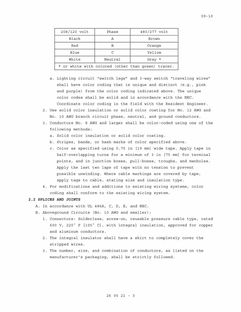
09-10
26 05 21 - 3
208/120 volt Phase 480/277 volt
Black A Brown
Red B Orange
Blue C Yellow
White Neutral Gray *
* or white with colored (other than green) tracer.
a. Lighting circuit “switch legs” and 3-way switch “traveling wires”
shall have color coding that is unique and distinct (e.g., pink
and purple) from the color coding indicated above. The unique
color codes shall be solid and in accordance with the NEC.
Coordinate color coding in the field with the Resident Engineer.
2. Use solid color insulation or solid color coating for No. 12 AWG and
No. 10 AWG branch circuit phase, neutral, and ground conductors.
3. Conductors No. 8 AWG and larger shall be color-coded using one of the
following methods:
a. Solid color insulation or solid color coating.
b. Stripes, bands, or hash marks of color specified above.
c. Color as specified using 0.75 in [19 mm] wide tape. Apply tape in
half-overlapping turns for a minimum of 3 in [75 mm] for terminal
points, and in junction boxes, pull-boxes, troughs, and manholes.
Apply the last two laps of tape with no tension to prevent
possible unwinding. Where cable markings are covered by tape,
apply tags to cable, stating size and insulation type.
4. For modifications and additions to existing wiring systems, color
coding shall conform to the existing wiring system.
2.2 SPLICES AND JOINTS
A. In accordance with UL 486A, C, D, E, and NEC.
B. Aboveground Circuits (No. 10 AWG and smaller):
1. Connectors: Solderless, screw-on, reusable pressure cable type, rated
600 V, 220˚ F [105˚ C], with integral insulation, approved for copper
and aluminum conductors.
2. The integral insulator shall have a skirt to completely cover the
stripped wires.
3. The number, size, and combination of conductors, as listed on the
manufacturer's packaging, shall be strictly followed.
09-10
26 05 21 - 4
C. Aboveground Circuits (No. 8 AWG and larger):
1. Connectors shall be indent, hex screw, or bolt clamp-type of high
conductivity and corrosion-resistant material, listed for use with
copper and aluminum conductors.
2. Field-installed compression connectors for cable sizes 250 kcmil and
larger shall have not fewer than two clamping elements or compression
indents per wire.
3. Insulate splices and joints with materials approved for the
particular use, location, voltage, and temperature. Splice and joint
insulation level shall be not less than the insulation level of the
conductors being joined.
4. Plastic electrical insulating tape: Per ASTM D2304, flame-retardant,
cold and weather resistant.
2.3 CONTROL WIRING
A. Unless otherwise specified elsewhere in these specifications, control
wiring shall be as specified for power and lighting wiring, except that
the minimum size shall be not less than No. 14 AWG.
B. Control wiring shall be large enough such that the voltage drop under
in-rush conditions does not adversely affect operation of the controls.
2.4 WIRE LUBRICATING COMPOUND
A. Lubricating compound shall be suitable for the wire insulation and
conduit, and shall not harden or become adhesive.
PART 3 - EXECUTION
3.1 GENERAL
A. Install in accordance with the NEC, and as specified.
B. Install all wiring in raceway systems.
C. Splice cables and wires only in outlet boxes, junction boxes, pull-
boxes, manholes, or handholes.
D. Wires of different systems (e.g., 120 V, 277 V) shall not be installed
in the same conduit or junction box system.
E. Install cable supports for all vertical feeders in accordance with the
NEC. Provide split wedge type which firmly clamps each individual cable
and tightens due to cable weight.
F. For panel boards, cabinets, wireways, switches, and equipment
assemblies, neatly form, train, and tie the cables in individual
circuits.
G. Seal cable and wire entering a building from underground between the
wire and conduit where the cable exits the conduit, with a non-hardening
approved compound.
H. Wire Pulling:
09-10
26 05 21 - 5
1. Provide installation equipment that will prevent the cutting or
abrasion of insulation during pulling of cables. Use lubricants
approved for the cable.
2. Use nonmetallic ropes for pulling feeders.
3. Attach pulling lines for feeders by means of either woven basket
grips or pulling eyes attached directly to the conductors, as
approved by the Resident Engineer.
4. All cables in a single conduit shall be pulled simultaneously.
5. Do not exceed manufacturer’s recommended maximum pulling tensions and
sidewall pressure values.
I. No more than three single-phase branch circuits shall be installed in
any one conduit.
3.2 SPLICE INSTALLATION
A. Splices and terminations shall be mechanically and electrically secure.
B. Tighten electrical connectors and terminals according to manufacturer's
published torque values.
C. Where the Government determines that unsatisfactory splices or
terminations have been installed, remove the devices and install
approved devices at no additional cost to the Government.
3.3 FEEDER IDENTIFICATION
A. In each interior pull-box and junction box, install metal tags on all
circuit cables and wires to clearly designate their circuit
identification and voltage. The tags shall be the embossed brass type,
1.5 in [40 mm] in diameter and 40 mils thick. Attach tags with plastic
ties.
3.4 EXISTING WIRING
Unless specifically indicated on the plans, existing wiring shall not be
reused for a new installation.
3.5 CONTROL AND SIGNAL WIRING INSTALLATION
A. Unless otherwise specified in other sections, install wiring and connect
to equipment/devices to perform the required functions as shown and
specified.
B. Except where otherwise required, install a separate power supply circuit
for each system so that malfunctions in any system will not affect other
systems.
C. Where separate power supply circuits are not shown, connect the systems
to the nearest panel boards of suitable voltages, which are intended to
supply such systems and have suitable spare circuit breakers or space
for installation.

09-10
26 05 21 - 6
3.6 CONTROL AND SIGNAL SYSTEM WIRING IDENTIFICATION
A. Install a permanent wire marker on each wire at each termination.
B. Identifying numbers and letters on the wire markers shall correspond to
those on the wiring diagrams used for installing the systems.
C. Wire markers shall retain their markings after cleaning.
3.7 ACCEPTANCE CHECKS AND TESTS
A. Feeders and branch circuits shall have their insulation tested after
installation and before connection to utilization devices, such as
fixtures, motors, or appliances. Test each conductor with respect to
adjacent conductors and to ground. Existing conductors to be reused
shall also be tested.
B. Applied voltage shall be 500VDC for 300-volt rated cable, and 1000VDC
for 600-volt rated cable. Apply test for one minute or until reading is
constant for 15 seconds, whichever is longer. Minimum insulation
resistance values shall not be less than 25 megohms for 300-volt rated
cable and 100 megohms for 600-volt rated cable.
C. Perform phase rotation test on all three-phase circuits.
D. The contractor shall furnish the instruments, materials, and labor for
all tests.
- - - E N D - - -
09-10
26 05 26 - 1
SECTION 26 05 26 GROUNDING AND BONDING FOR ELECTRICAL SYSTEMS
PART 1 - GENERAL
1.1 DESCRIPTION
A. This section specifies the general grounding and bonding requirements
for electrical equipment and operations to provide a low impedance path
for possible ground fault currents.
B. “Grounding electrode system” refers to all electrodes required by NEC,
as well as made, supplementary, and lightning protection system
grounding electrodes.
C. The terms “connect” and “bond” are used interchangeably in this
specification and have the same meaning.
1.2 RELATED WORK
A. Section 26 05 11, REQUIREMENTS FOR ELECTRICAL INSTALLATIONS: General
electrical requirements and items that are common to more than one
section of Division 26.
B. Section 26 05 21, LOW-VOLTAGE ELECTRICAL POWER CONDUCTORS AND CABLES
(600 VOLTS AND BELOW): Low Voltage power and lighting wiring.
1.3 QUALITY ASSURANCE
Refer to Paragraph, QUALIFICATIONS, in Section 26 05 11, REQUIREMENTS
FOR ELECTRICAL INSTALLATIONS.
1.4 SUBMITTALS
A. Submit in accordance with Section 26 05 11, REQUIREMENTS FOR ELECTRICAL
INSTALLATIONS.
B. Shop Drawings:
1. Clearly present enough information to determine compliance with
drawings and specifications.
2. Include the location of system grounding electrode connections and
the routing of aboveground and underground grounding electrode
conductors.
C. Test Reports: Provide certified test reports of ground resistance.
D. Certifications: Two weeks prior to final inspection, submit four copies
of the following to the Resident Engineer:
1. Certification that the materials and installation are in accordance
with the drawings and specifications.
2. Certification by the contractor that the complete installation has
been properly installed and tested.
09-10
26 05 26 - 2
1.5 APPLICABLE PUBLICATIONS
Publications listed below (including amendments, addenda, revisions,
supplements, and errata) form a part of this specification to the
extent referenced. Publications are referenced in the text by
designation only.
A. American Society for Testing and Materials (ASTM):
B1-07...................Standard Specification for Hard-Drawn Copper
Wire
B3-07...................Standard Specification for Soft or Annealed
Copper Wire
B8-04...................Standard Specification for Concentric-Lay-
Stranded Copper Conductors, Hard, Medium-Hard,
or Soft
B. Institute of Electrical and Electronics Engineers, Inc. (IEEE):
81-1983.................IEEE Guide for Measuring Earth Resistivity,
Ground Impedance, and Earth Surface Potentials
of a Ground System
C2-07...................National Electrical Safety Code
C. National Fire Protection Association (NFPA):
70-08...................National Electrical Code (NEC)
99-2005.................Health Care Facilities
D. Underwriters Laboratories, Inc. (UL):
44-05 ..................Thermoset-Insulated Wires and Cables
83-08 ..................Thermoplastic-Insulated Wires and Cables
467-07 .................Grounding and Bonding Equipment
486A-486B-03 ...........Wire Connectors
PART 2 - PRODUCTS
2.1 GROUNDING AND BONDING CONDUCTORS
A. Equipment grounding conductors shall be UL 44 or UL 83 insulated
stranded copper, except that sizes No. 10 AWG [6 mm²] and smaller shall
be solid copper. Insulation color shall be continuous green for all
equipment grounding conductors, except that wire sizes No. 4 AWG [25
mm²] and larger shall be identified per NEC.
B. Bonding conductors shall be ASTM B8 bare stranded copper, except that
sizes No. 10 AWG [6 mm²] and smaller shall be ASTM B1 solid bare copper
wire.
C. Conductor sizes shall not be less than shown on the drawings, or not
less than required by the NEC, whichever is greater.

09-10
26 05 26 - 3
PART 3 - EXECUTION
3.1 GENERAL
A. Ground in accordance with the NEC, as shown on drawings, and as
specified herein.
B. System Grounding:
1. Secondary service neutrals: Ground at the supply side of the
secondary disconnecting means and at the related transformers.
2. Separately derived systems (transformers downstream from the service
entrance): Ground the secondary neutral.
C. Equipment Grounding: Metallic structures, including ductwork and
building steel, enclosures, raceways, junction boxes, outlet boxes,
cabinets, machine frames, and other conductive items in close proximity
with electrical circuits, shall be bonded and grounded.
3.2 RACEWAY
A. Conduit Systems:
1. Ground all metallic conduit systems. All metallic conduit systems
shall contain an equipment grounding conductor.
2. Non-metallic conduit systems, except non-metallic feeder conduits
that carry a grounded conductor from exterior transformers to
interior or building-mounted service entrance equipment, shall
contain an equipment grounding conductor.
3. Conduit that only contains a grounding conductor, and is provided
for its mechanical protection, shall be bonded to that conductor at
the entrance and exit from the conduit.
4. Metallic conduits which terminate without mechanical connection to
an electrical equipment housing by means of locknut and bushings or
adapters, shall be provided with grounding bushings. Connect
bushings with a bare grounding conductor to the equipment ground
bus.
B. Feeders and Branch Circuits: Install equipment grounding conductors
with all feeders and power and lighting branch circuits.
C. Boxes, Cabinets, Enclosures, and Panelboards:
1. Bond the equipment grounding conductor to each pullbox, junction
box, outlet box, device box, cabinets, and other enclosures through
which the conductor passes (except for special grounding systems for
intensive care units and other critical units shown).
2. Provide lugs in each box and enclosure for equipment grounding
conductor termination.
09-10
26 05 26 - 4
D. Wireway Systems:
1. Bond the metallic structures of wireway to provide 100% electrical
continuity throughout the wireway system, by connecting a No. 6 AWG
[16 mm²] bonding jumper at all intermediate metallic enclosures and
across all section junctions.
2. Install insulated No. 6 AWG [16 mm²] bonding jumpers between the
wireway system, bonded as required above, and the closest building
ground at each end and approximately every 50 ft [16 M].
3. Use insulated No. 6 AWG [16 mm²] bonding jumpers to ground or bond
metallic wireway at each end for all intermediate metallic
enclosures and across all section junctions.
4. Use insulated No. 6 AWG [16 mm²] bonding jumpers to ground cable
tray to column-mounted building ground plates (pads) at each end and
approximately every 49 ft [15 M].
E. Receptacles shall not be grounded through their mounting screws. Ground
receptacles with a jumper from the receptacle green ground terminal to
the device box ground screw and a jumper to the branch circuit
equipment grounding conductor.
F. Ground lighting fixtures to the equipment grounding conductor of the
wiring system when the green ground is provided; otherwise, ground the
fixtures through the conduit systems. Fixtures connected with flexible
conduit shall have a green ground wire included with the power wires
from the fixture through the flexible conduit to the first outlet box.
G. Fixed electrical appliances and equipment shall be provided with a
ground lug for termination of the equipment grounding conductor.
- - - E N D - - -
09-10
26 05 33 - 1
SECTION 26 05 33 RACEWAY AND BOXES FOR ELECTRICAL SYSTEMS
PART 1 - GENERAL
1.1 DESCRIPTION
A. This section specifies the furnishing, installation, and connection of
conduit, fittings, and boxes, to form complete, coordinated, grounded
raceway systems. Raceways are required for all wiring unless shown or
specified otherwise.
B. Definitions: The term conduit, as used in this specification, shall mean
any or all of the raceway types specified.
1.2 RELATED WORK
A. Section 26 05 11, REQUIREMENTS FOR ELECTRICAL INSTALLATIONS: General
electrical requirements and items that are common to more than one
section of Division 26.
B. Section 26 05 26, GROUNDING AND BONDING FOR ELECTRICAL SYSTEMS:
Requirements for personnel safety and to provide a low impedance path
for possible ground fault currents.
1.3 QUALITY ASSURANCE
Refer to Paragraph, QUALIFICATIONS, in Section 26 05 11, REQUIREMENTS
FOR ELECTRICAL INSTALLATIONS.
1.4 SUBMITTALS
In accordance with Section 26 05 11, REQUIREMENTS FOR ELECTRICAL
INSTALLATIONS, submit the following:
A. Manufacturer's Literature and Data: Showing each cable type and rating.
The specific item proposed and its area of application shall be
identified on the catalog cuts.
B. Shop Drawings:
1. Size and location of panels and pull-boxes.
2. Layout of required conduit penetrations through structural elements.
C. Certifications:
1. Two weeks prior to the final inspection, submit four copies of the
following certifications to the Resident Engineer:
a. Certification by the manufacturer that the material conforms to
the requirements of the drawings and specifications.
b. Certification by the contractor that the material has been
properly installed.

09-10
26 05 33 - 2
1.5 APPLICABLE PUBLICATIONS
A. Publications listed below (including amendments, addenda, revisions,
supplements, and errata) form a part of this specification to the extent
referenced. Publications are referenced in the text by designation only.
B. American National Standards Institute (ANSI):
C80.1-05................Electrical Rigid Steel Conduit
C80.3-05................Steel Electrical Metal Tubing
C80.6-05................Electrical Intermediate Metal Conduit
C. National Fire Protection Association (NFPA):
70-08...................National Electrical Code (NEC)
D. Underwriters Laboratories, Inc. (UL):
1-05....................Flexible Metal Conduit
5-04....................Surface Metal Raceway and Fittings
6-07....................Electrical Rigid Metal Conduit - Steel
50-95...................Enclosures for Electrical Equipment
360-093.................Liquid-Tight Flexible Steel Conduit
467-07..................Grounding and Bonding Equipment
514A-04.................Metallic Outlet Boxes
514B-04.................Conduit, Tubing, and Cable Fittings
514C-96.................Nonmetallic Outlet Boxes, Flush-Device Boxes and
Covers
651-05..................Schedule 40 and 80 Rigid PVC Conduit and
Fittings
651A-00.................Type EB and A Rigid PVC Conduit and HDPE Conduit
797-07..................Electrical Metallic Tubing
1242-06.................Electrical Intermediate Metal Conduit - Steel
E. National Electrical Manufacturers Association (NEMA):
TC-2-03.................Electrical Polyvinyl Chloride (PVC) Tubing and
Conduit
TC-3-04.................PVC Fittings for Use with Rigid PVC Conduit and
Tubing
FB1-07..................Fittings, Cast Metal Boxes and Conduit Bodies
for Conduit, Electrical Metallic Tubing and
Cable
PART 2 - PRODUCTS
2.1 MATERIAL
A. Conduit Size: In accordance with the NEC, but not less than 0.5 in [13
mm] unless otherwise shown. Where permitted by the NEC, 0.5 in [13 mm]
flexible conduit may be used for tap connections to recessed lighting
fixtures.

09-10
26 05 33 - 3
B. Conduit:
1. Electrical metallic tubing (EMT): Shall conform to UL 797 and ANSI
C80.3. Maximum size not to exceed 4 in [105 mm] and shall be
permitted only with cable rated 600 V or less.
C. Conduit Fittings:
1. Electrical metallic tubing fittings:
a. Fittings and conduit bodies shall meet the requirements of UL
514B, ANSI C80.3, and NEMA FB1.
b. Only steel or malleable iron materials are acceptable.
c. Setscrew couplings and connectors: Use setscrews of case-hardened
steel with hex head and cup point, to firmly seat in wall of
conduit for positive grounding.
d. Indent-type connectors or couplings are prohibited.
e. Die-cast or pressure-cast zinc-alloy fittings or fittings made of
"pot metal" are prohibited.
D. Conduit Supports:
1. Parts and hardware: Zinc-coat or provide equivalent corrosion
protection.
2. Individual Conduit Hangers: Designed for the purpose, having a
pre-assembled closure bolt and nut, and provisions for receiving a
hanger rod.
3. Multiple conduit (trapeze) hangers: Not less than 1.5 x 1.5 in [38 mm
x 38 mm], 12-gauge steel, cold-formed, lipped channels; with not less
than 0.375 in [9 mm] diameter steel hanger rods.
4. Solid Masonry and Concrete Anchors: Self-drilling expansion shields,
or machine bolt expansion.
E. Outlet, Junction, and Pull Boxes:
1. UL-50 and UL-514A.
2. Cast metal where required by the NEC or shown, and equipped with
rustproof boxes.
3. Sheet metal boxes: Galvanized steel, except where otherwise shown.
4. Flush-mounted wall or ceiling boxes shall be installed with raised
covers so that the front face of raised cover is flush with the wall.
Surface-mounted wall or ceiling boxes shall be installed with
surface-style flat or raised covers.
F. Wireways: Equip with hinged covers, except where removable covers are shown. Include couplings, offsets, elbows, expansion joints, adapters,
hold-down straps, end caps, and other fittings to match and mate with
wireways as required for a complete system.

09-10
26 05 33 - 4
PART 3 - EXECUTION
3.1 PENETRATIONS
A. Cutting or Holes:
1. Cut holes in advance where they should be placed in the structural
elements, such as ribs or beams. Obtain the approval of the Resident
Engineer prior to drilling through structural elements.
2. Cut holes through concrete and masonry in new and existing structures
with a diamond core drill or concrete saw. Pneumatic hammers, impact
electric, hand, or manual hammer-type drills are not allowed, except
where permitted by the Resident Engineer as required by limited
working space.
B. Firestop: Where conduits, wireways, and other electrical raceways pass
through fire partitions, fire walls, smoke partitions, or floors,
install a fire stop that provides an effective barrier against the
spread of fire, smoke and gases as specified in Section 07 84 00,
FIRESTOPPING.
3.2 INSTALLATION, GENERAL
A. In accordance with UL, NEC, as shown, and as specified herein.
B. Essential (Emergency) raceway systems shall be entirely independent of
other raceway systems, except where shown on drawings.
C. Install conduit as follows:
1. In complete mechanically and electrically continuous runs before
pulling in cables or wires.
2. Unless otherwise indicated on the drawings or specified herein,
installation of all conduits shall be concealed within finished
walls, floors, and ceilings.
3. Flattened, dented, or deformed conduit is not permitted. Remove and
replace the damaged conduits with new undamaged material.
4. Assure conduit installation does not encroach into the ceiling height
head room, walkways, or doorways.
5. Cut square, ream, remove burrs, and draw up tight.
6. Independently support conduit at 8 ft [2.4 M] on centers. Do not use
other supports, i.e., suspended ceilings, suspended ceiling
supporting members, lighting fixtures, conduits, mechanical piping,
or mechanical ducts.
7. Support within 12 in [300 mm] of changes of direction, and within 12
in [300 mm] of each enclosure to which connected.
8. Close ends of empty conduit with plugs or caps at the rough-in stage
until wires are pulled in, to prevent entry of debris.
09-10
26 05 33 - 5
9. Conduit installations under fume and vent hoods are prohibited.
10. Secure conduits to cabinets, junction boxes, pull-boxes, and outlet
boxes with bonding type locknuts. For rigid and IMC conduit
installations, provide a locknut on the inside of the enclosure, made
up wrench tight. Do not make conduit connections to junction box
covers.
11. Flashing of penetrations of the roof membrane is specified in Section
07 60 00, FLASHING AND SHEET METAL.
12. Conduit bodies shall only be used for changes in direction, and shall
not contain splices.
D. Conduit Bends:
1. Make bends with standard conduit bending machines.
2. Conduit hickey may be used for slight offsets and for straightening
stubbed out conduits.
3. Bending of conduits with a pipe tee or vise is prohibited.
E. Layout and Homeruns:
1. Install conduit with wiring, including homeruns, as shown on
drawings.
2. Deviations: Make only where necessary to avoid interferences and only
after drawings showing the proposed deviations have been submitted
approved by the Resident Engineer.
3.3 CONCEALED WORK INSTALLATION
A. In Concrete:
1. Conduit: Rigid steel, IMC, or EMT. Do not install EMT in concrete
slabs that are in contact with soil, gravel, or vapor barriers.
2. Align and run conduit in direct lines.
3. Install conduit through concrete beams only:
a. Where shown on the structural drawings.
b. As approved by the Resident Engineer prior to construction, and
after submittal of drawing showing location, size, and position of
each penetration.
4. Installation of conduit in concrete that is less than 3 in [75 mm]
thick is prohibited.
a. Conduit outside diameter larger than one-third of the slab
thickness is prohibited.
b. Space between conduits in slabs: Approximately six conduit
diameters apart, and one conduit diameter at conduit crossings.
c. Install conduits approximately in the center of the slab so that
there will be a minimum of 0.75 in [19 mm] of concrete around the
conduits.
09-10
26 05 33 - 6
5. Make couplings and connections watertight. Use thread compounds that
are UL approved conductive type to ensure low resistance ground
continuity through the conduits. Tightening setscrews with pliers is
prohibited.
B. Above Furred or Suspended Ceilings and in Walls:
SPEC WRITER NOTE: Edit paragraphs below per project requirements.
1. Conduit for conductors 600 V and below: EMT. Mixing different types
of conduits indiscriminately in the same system is prohibited.
2. Align and run conduit parallel or perpendicular to the building
lines.
3. Connect recessed lighting fixtures to conduit runs with maximum 6 ft
[1.8 M] of flexible metal conduit extending from a junction box to
the fixture.
4. Tightening setscrews with pliers is prohibited.
3.4 EXPOSED WORK INSTALLATION
A. Unless otherwise indicated on the drawings, exposed conduit is only
permitted in mechanical and electrical rooms.
B. Conduit for Conductors 600 V and Below: EMT. Mixing different types of
conduits indiscriminately in the system is prohibited.
C. Align and run conduit parallel or perpendicular to the building lines.
D. Install horizontal runs close to the ceiling or beams and secure with
conduit straps.
E. Support horizontal or vertical runs at not over 8 ft [2.4 M] intervals.
F. Surface metal raceways: Use only where shown.
G. Painting:
1. Paint exposed conduit as specified in Section 09 91 00, PAINTING.
2. Paint all conduits containing cables rated over 600 V safety orange.
Refer to Section 09 91 00, PAINTING for preparation, paint type, and
exact color. In addition, paint legends, using 2 in [50 mm] high
black numerals and letters, showing the cable voltage rating. Provide
legends where conduits pass through walls and floors and at maximum
20 ft [6 M] intervals in between.
3.5 MOTORS AND VIBRATING EQUIPMENT
A. Use flexible metal conduit for connections to motors and other
electrical equipment subject to movement, vibration, misalignment,
cramped quarters, or noise transmission.
B. Use liquid-tight flexible metal conduit for installation in exterior
locations, moisture or humidity laden atmosphere, corrosive atmosphere,
water or spray wash-down operations, inside airstream of HVAC units, and
09-10
26 05 33 - 7
locations subject to seepage or dripping of oil, grease, or water.
Provide a green equipment grounding conductor with flexible metal
conduit.
3.6 EXPANSION JOINTS
A. Provide conduits smaller than 3 in [75 mm] with junction boxes on both
sides of the expansion joint. Connect conduits to junction boxes with
sufficient slack of flexible conduit to produce 5 in [125 mm] vertical
drop midway between the ends. Flexible conduit shall have a bonding
jumper installed. In lieu of this flexible conduit, expansion and
deflection couplings as specified above for conduits 15 in [375 mm] and
larger are acceptable.
3.7 CONDUIT SUPPORTS, INSTALLATION
A. Safe working load shall not exceed one-quarter of proof test load of
fastening devices.
B. Use pipe straps or individual conduit hangers for supporting individual
conduits.
C. Support multiple conduit runs with trapeze hangers. Use trapeze hangers
that are designed to support a load equal to or greater than the sum of
the weights of the conduits, wires, hanger itself, and 200 lbs [90 kg].
Attach each conduit with U-bolts or other approved fasteners.
D. Support conduit independently of junction boxes, pull-boxes, fixtures,
suspended ceiling T-bars, angle supports, and similar items.
E. Fasteners and Supports in Solid Masonry and Concrete:
1. New Construction: Use steel or malleable iron concrete inserts set in
place prior to placing the concrete.
2. Existing Construction:
a. Steel expansion anchors not less than 0.25 in [6 mm] bolt size and
not less than 1.125 in [28 mm] embedment.
b. Power set fasteners not less than 0.25 in [6 mm] diameter with
depth of penetration not less than 3 in [75 mm].
c. Use vibration and shock-resistant anchors and fasteners for
attaching to concrete ceilings.
E. Hollow Masonry: Toggle bolts.
F. Bolts supported only by plaster or gypsum wallboard are not acceptable.
G. Metal Structures: Use machine screw fasteners or other devices
specifically designed and approved for the application.
H. Attachment by wood plugs, rawl plug, plastic, lead or soft metal
anchors, or wood blocking and bolts supported only by plaster is
prohibited.
09-10
26 05 33 - 8
I. Chain, wire, or perforated strap shall not be used to support or fasten
conduit.
J. Spring steel type supports or fasteners are prohibited for all uses
except horizontal and vertical supports/fasteners within walls.
K. Vertical Supports: Vertical conduit runs shall have riser clamps and
supports in accordance with the NEC and as shown. Provide supports for
cable and wire with fittings that include internal wedges and retaining
collars.
3.8 BOX INSTALLATION
A. Boxes for Concealed Conduits:
1. Flush-mounted.
2. Provide raised covers for boxes to suit the wall or ceiling,
construction, and finish.
B. In addition to boxes shown, install additional boxes where needed to
prevent damage to cables and wires during pulling-in operations.
C. Remove only knockouts as required and plug unused openings. Use threaded
plugs for cast metal boxes and snap-in metal covers for sheet metal
boxes.
D. Outlet boxes mounted back-to-back in the same wall are prohibited. A
minimum 24 in [600 mm] center-to-center lateral spacing shall be
maintained between boxes.
E. Minimum size of outlet boxes for ground fault interrupter (GFI)
receptacles is 4 in [100 mm] square x 2.125 in [55 mm] deep, with device
covers for the wall material and thickness involved.
F. Stencil or install phenolic nameplates on covers of the boxes identified
on riser diagrams; for example "SIG-FA JB No. 1."
G. On all branch circuit junction box covers, identify the circuits with
black marker.
- - - E N D - - -

Technical Specification Sheet
Page 1 of 12
BT300 HVAC Drives
Figure 1. BT300 HVAC Drive without and with Integral Disconnect.
DescriptionBT300 is designed specifically for the demands oftoday’s HVAC systems. Increased focus on energy efficiency of variable flow systems has increased the need for easy-to-use and highly reliable variablefrequency drives that reduce the cost of installationand maintenance while maximizing energy savings.
The BT300 comes standard with unique and industry-leading features:
Motor Switch Ride Through – during maintenancethe motor maintenance switch can be opened and closed without stopping or tripping the drive Thin Film Capacitors – eliminate the need tocondition or reform the capacitors before applying powerView/Monitor nine parameters at one time – userselectable, users determine the parameters for their applications Smallest Type 12 footprint on the market – lowershipping cost and easy installation
Designed for HVAC HVAC demands are unique to other drive applications. The BT300 is singularly focused on the needs of HVAC variable flow systems:
Built-in wizards for start-up and easy setup ofadvanced functions
– PID Start-up Wizard– Multi-pump Wizard– Fire Mode WizardIntegrated harmonic filters reducing noise andinterference eliminating the need for additionalfilters and reactors.BT300 Thin Film Capacitors do not requireconditioning. Immediate drive replacement ispossible.Standard Integration Protocols (BACnet, LON,Modbus)Two built-in PID controllers for fast and accurateprocess controlBuilt-in fire mode controllerEnergy Savings with > 97.5% efficiencyOptimized cooling fansUL Type 1 and Type 12 – Same Size208V to 240V 1 HP to 125 HP380V to 480V 1.5 HP to 250 HPOptional integrated drive disconnectAdvanced I/O expansion capability built into thedriveOne common interface throughout all powerrangesIntuitive graphical keypad with multilingual display.
Suggested Manufacturer:Siemens Industry or approved equal.

Page 2 of 12
Ease of Use The BT300 drives are easy to use, easy to understand and easy to program. This means installed cost and maintenance savings. Information you want for your specific operation:
Built-in Help Menu – explains each parameterBuilt-in Maintenance Manual - shows possiblecauses and suggested remediesNine user-selected values can be defined andmonitored at one time – providing you with all theinformation you need at a glance
Embedded Ethernet and RS-485 - No additionalhardware or cost for Ethernet. Standard HVACprotocols out-of-the-box.
– BACnet IP– BACnet MS/TP– Modbus TCP– Modbus RTU– Metasys N2
World-class Standard of Quality The BT300's reliability is a result of extensive testing from design to deployment. This testing includes highly accelerated stress testing in extremetemperatures, vibration, and humidity as well ascurrent and voltage variations. Not only will the BT300 withstand most power situations and demanding environmental conditions, it will provide confidence and peace of mind knowing that it will not fail, ensuring a long, trouble-free installation.
Investment Protection The BT300 HVAC Drive is backward compatible to SED2 installations. A migration kit to mount a BT300 Drive in place of an SED2 to support the existing conventional or electronic bypass fail is an ideal solution to moving your technology forward at the lowest possible cost. The SED2 to BT300 Migration Kits provide you with all the components necessary to mount your BT300 quickly and easily in various locations within your facility.
Environmentally Responsible The BT300 saves energy, is environmentally safe and RoHS Compliant. All BT300s are constructed with lead-free circuit boards and produce no hazardous waste. They use the latest technologies for insulated-gate bipolar transistors (IGBT) and power capacitors. The thin-film power capacitors do not contain toxic electrolytes; therefore, the BT300 capacitors will not dry out. There is no need to “wake up” or condition the capacitors before installing. Your BT300 is safe to connect even after years of storage.
The BT300 IGBT design results in lower heat losses and lower operating temperatures. It weighs 40% less than competitors' models decreasing the cost of shipping and allowing for easier installation. An average BT300 generates 68% to 125% fewer CO2 emissions than heavier competitors' drives during shipping.

Page 3 of 12
Product Numbers (1) B T 3 0 0 - 0 0 1 X 2 - 0 1 XExample Product
Numbers (2) B T 3 0 0 - 0 0 1 5 4 - 1 2 D LModelBT300 VFD only Separator HP1, 1.5, 2, 3, 5, 7.5, 10,15 20, 25, 30, 40, 50, 60, 75 100, 125, 150, 200, 250
X No fraction HP 5 1/2 HP
Voltage2 200 to 240 4 380 to 480
Separator NEMA Enclosure
01 Type 1 12 Type 12
Type X Drive only D Integral Disconnect Switch (available in Type 12 only)
OptionsL LON card installed
Example (1) = 1 HP, 208V Drive in Type 1 enclosure
(2) = 1.5 HP, 480V Drive in Type 12 enclosure with an integral disconnect switch and LON card.
Frame Sizes and Power Ranges (BT300 Type 1 and Type 12) KW 0.75 1.1 1.5 2.2 4 5.5 7.5 11 15 18.5 22 30 37 45 55 75 90 110 132 160
Voltage HP 1 1.5 2 3 5 7.5 10 15 20 25 30 40 50 60 75 100 125 150 200 250
208V 4 5 6 7 8 9
480V
Fram
e Si
ze 4 5 6 7 8 9
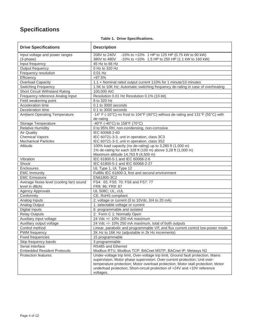
Page 4 of 12
SpecificationsTable 1. Drive Specifications.
Drive Specifications Description
Input voltage and power ranges (3-phase)
208V to 240V -10% to +10% 1 HP to 125 HP (0.75 kW to 90 kW) 380V to 480V -10% to +10% 1.5 HP to 250 HP (1.1 kW to 160 kW)
Input frequency 45 Hz to 66 Hz Output frequency 0 Hz to 320 Hz Frequency resolution 0.01 Hz Efficiency >97.5% Overload Capacity 1.1 × Nominal rated output current 110% for 1 minute/10 minutes Switching Frequency 1.5K to 10K Hz; Automatic switching frequency de-rating in case of overheating Short Circuit Withstand Rating 100,000 AIC Frequency reference Analog Input Resolution 0.01 Hz Resolution 0.1% (10-bit) Field weakening point 8 to 320 Hz Acceleration time 0.1 to 3000 seconds Deceleration time 0.1 to 3000 seconds Ambient Operating Temperature -14° F (-10°C) no frost to 104°F (40°C) without de-rating and 131°F (55°C) with
de-rating Storage Temperature -40°F (-40°C) to 158°F (70°C) Relative Humidity 0 to 95% RH, non-condensing, non-corrosive Air Quality Chemical Vapors Mechanical Particles
IEC 60068-2-60 IEC 60721-3-3, unit in operation, class 3C3 IEC 60721-3-3, unit in operation, class 3S2
Altitude 100% load capacity (no de-rating) up to 3,280 ft (1,000 m) 1% de-rating for each 328 ft (100 m) above 3,28 ft (1,000 m) Maximum altitude 14,763 ft (4,500 m)
Vibration IEC 61800-5-1 and IEC 60068-2-6 Shock IEC 61800-5-1 and IEC 60068-2-27 Enclosures UL Type 1, UL Type 12 EMC Immunity Fulfills IEC 61800-3, first and second environment EMC Emissions EN61800-3C2 Average Noise level (cooling fan) sound level in dB(A)
FS4: 65; FS5: 70; FS6 and FS7: 77 FR8: 86; FR9: 87
Agency Approvals UL 508C; UL, cUL Conformity CE, RoHS compliant Analog Inputs 2: voltage or current (0 to 10Vdc, 0/4 to 20 mA) Analog Output 1: selectable voltage or current Digital Inputs 6: programmable and isolated Relay Outputs 2: Form C 1: Normally Open Auxiliary input voltage 24 Vdc +/- 10% 250 mA maximum Auxiliary output voltage 24 Vdc +/- 10% 250 mA maximum, total of both outputs Control method Linear, parabolic and programmable V/f; and flux current control low-power mode PWM frequency 2K Hz to 16K Hz (adjustable in 2k Hz increments) Fixed frequencies 15 programmable Skip frequency bands 3 programmable Serial Interface Embedded Resident Protocols
RS485 and Ethernet Modbus RTU, Modbus TCP: BACnet MSTP, BACnet IP; Metasys N2
Protection features Under-voltage trip limit, Over-voltage trip limit, Ground fault protection, Mains supervision; Motor phase supervision; Over-current protection; Unit over-temperature protection; Motor overload protection; Motor stall protection; Motor underload protection; Short-circuit protection of +24V and +10V reference voltages.

Page 5 of 12
Specifications, Continued Table 2. Output Ratings.
Description Output Rating
Output Rating
Rated Continuous
Current Frame Size Voltage
(±10%) UL Type 1 UL Type 12 UL Type 12 with
Drive Disconnect HP kW
BT300-001X2-01X BT300-001X2-12X BT300-001X2-12D 1.0 0.75 4.8 FS4 BT300-00152-01X BT300-00152-12X BT300-00152-12D 1.5 1.1 6.7 FS4 BT300-002X2-01X BT300-002X2-12X BT300-002X2-12D 2.0 1.5 8.0 FS4 BT300-003X2-01X BT300-003X2-12X BT300-003X2-12D 3.0 2.2 11.0 FS4 BT300-005X2-01X BT300-005X2-12X BT300-005X2-12D 5.0 3.0 18.0 FS5 BT300-00752-01X BT300-00752-12X BT300-00752-12D 7.5 5.5 24.0 FS5 BT300-010X2-01X BT300-010X2-12X BT300-010X2-12D 10.0 7.5 31.0 FS5 BT300-015X2-01X BT300-015X2-12X BT300-015X2-12D 15.0 11.0 48.0 FS6 BT300-020X2-01X BT300-020X2-12X BT300-020X2-12D 20.0 15.0 62.0 FS6 BT300-025X2-01X BT300-025X2-12X BT300-025X2-12D 25.0 18.5 75.0 FS7 BT300-030X2-01X BT300-030X2-12X BT300-030X2-12D 30.0 22.0 88.0 FS7 BT300-040X2-01X BT300-040X2-12X BT300-040X2-12D 40.0 30.0 105.0 FS7 BT300-050X2-01X BT300-050X2-12X — 50.0 37.0 140.0 FS8 BT300-060X2-01X BT300-060X2-12X — 60.0 45.0 170.0 FS8 BT300-075X2-01X BT300-075X2-12X — 75.0 55.0 205.0 FS8 BT300-100X2-01X BT300-100X2-12X — 100.0 75.0 261.0 FS9
208V and 230V to
240V(3-Phase)
BT300-125X2-01X BT300-125X2-12X — 125.0 90.0 310.0 FS9 BT300-00154-01X BT300-00154-12X BT300-00152-12D 1.5 1.1 3.7 FS4 BT300-002X4-01X BT300-002X4-12X BT300-002X4-12D 2.0 1.5 5.3 FS4 BT300-003X4-01X BT300-003X4-12X BT300-003X4-12D 3.0 2.2 6.2 FS4 BT300-005X4-01X BT300-005X4-12X BT300-005X4-12D 5.0 3.0 10.6 FS4 BT300-00754-01X BT300-00754-12X BT300-00752-12D 7.5 5.5 13.2 FS4 BT300-010X4-01X BT300-010X4-12X BT300-010X4-12D 10.0 7.5 16.0 FS5 BT300-015X4-01X BT300-015X4-12X BT300-015X4-12D 15.0 11.0 23.0 FS5 BT300-020X4-01X BT300-020X4-12X BT300-020X4-12D 20.0 15.0 31.0 FS5 BT300-025X4-01X BT300-025X4-12X BT300-025X4-12D 25.0 18.5 38.0 FS6 BT300-030X4-01X BT300-030X4-12X BT300-030X4-12D 30.0 22.0 46.0 FS6 BT300-040X4-01X BT300-040X4-12X BT300-040X4-12D 40.0 30.0 61.0 FS6 BT300-050X4-01X BT300-050X4-12X BT300-050X4-12D 50.0 37.0 72.0 FS7 BT300-060X4-01X BT300-060X4-12X BT300-060X4-12D 60.0 45.0 87.0 FS7 BT300-075X4-01X BT300-075X4-12X BT300-075X4-12D 75.0 55.0 105.0 FS7 BT300-100X4-01X BT300-100X4-12X — 100.0 75.0 140.0 FS8 BT300-125X4-01X BT300-125X4-12X — 125.0 90.0 170.0 FS8 BT300-150X4-01X BT300-150X4-12X — 150.0 110.0 205.0 FS8 BT300-200X4-01X BT300-200X4-12X — 200.0 132.0 261.0 FS9
380V to 480V
(3-Phase)
BT300-250X4-01X BT300-250X4-12X — 250.0 160.0 310.0 FS9
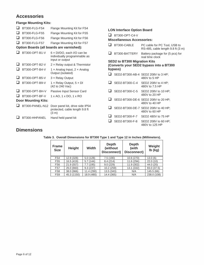
Page 6 of 12
AccessoriesFlange Mounting Kits:
BT300-FLG-FS4 Flange Mounting Kit for FS4 BT300-FLG-FS5 Flange Mounting Kit for FS5 BT300-FLG-FS6 Flange Mounting Kit for FS6BT300-FLG-FS7 Flange Mounting Kit for FS7
Option Boards (all boards are varnished): BT300-OPT-B1-V 6 × DI/DO, each I/O can be
individually programmable asinput or output
BT300-OPT-B2-V 2 × Relay output & Thermistor BT300-OPT-B4-V 1 × Analog Input, 2 × Analog
Output (isolated)BT300-OPT-B5-V 3 × Relay Output BT300-OPT-B9-V 1 × Relay Output, 5 × DI
(42 to 240 Vac) BT300-OPT-BH-V Passive Input Sensor Card BT300-OPT-BF-V 1 x AO, 1 x DO, 1 x RO
Door Mounting Kits: BT300-PANEL-N12 Door panel kit, drive side IP54
protected, cable length 9.8 ft (3 m)
BT300-HHPANEL Hand held panel kit
LON Interface Option Board BT300-OPT-C4-V
Miscellaneous Accessories: BT300-CABLE PC cable for PC Tool, USB to
RS-485, cable length 9.8 ft (3 m) BT300-BATTERY Battery package for (5 pcs) for
real time clock SED2 to BT300 Migration Kits (Converts your SED2 bypass into a BT300 bypass)
SED2-BT300-AB-4 SED2 208V to 3 HP; 480V to 5 HP
SED2-BT300-C-4 SED2 208V to 4 HP; 480V to 7.5 HP
SED2-BT300-C-5 SED2 208V to 10 HP; 480V to 20 HP
SED2-BT300-DE-6 SED2 208V to 20 HP; 480V to 40 HP
SED2-BT300-DE-7 SED2 208V to 40 HP; 480V to 60 HP
SED2-BT300-F-7 SED2 480V to 75 HP SED2-BT300-F-8 SED2 208V to 60 HP;
480V to 125 HP
Dimensions Table 3. Overall Dimensions for BT300 Type 1 and Type 12 in Inches (Millimeters).
FrameSize Height Width
Depth (without
Disconnect)
Depth (with
Disconnect) Weight lb (kg)
FS4 12.9 (328) 5.0 (128) 7.5 (190) 10.6 (270) 13.0 (6) FS5 16.5 (419) 5.7 (144) 8.4 (214) 11.6 (294) 22.0 (10) FS6 21.9 (557) 7.7 (195) 9.0 (229) 11.9 (302) 44.0 (20) FS7 26.0 (660) 9.3 (237) 10.2 (259) 13.1 (332) 83.0 (37.5) FS8 38.0 (966) 11.4 (290) 13.5 (343) N/A 145.5 (66) FS9 45.3 (1150) 18.9 (480) 14.4 (365) N/A 238.0 (108)
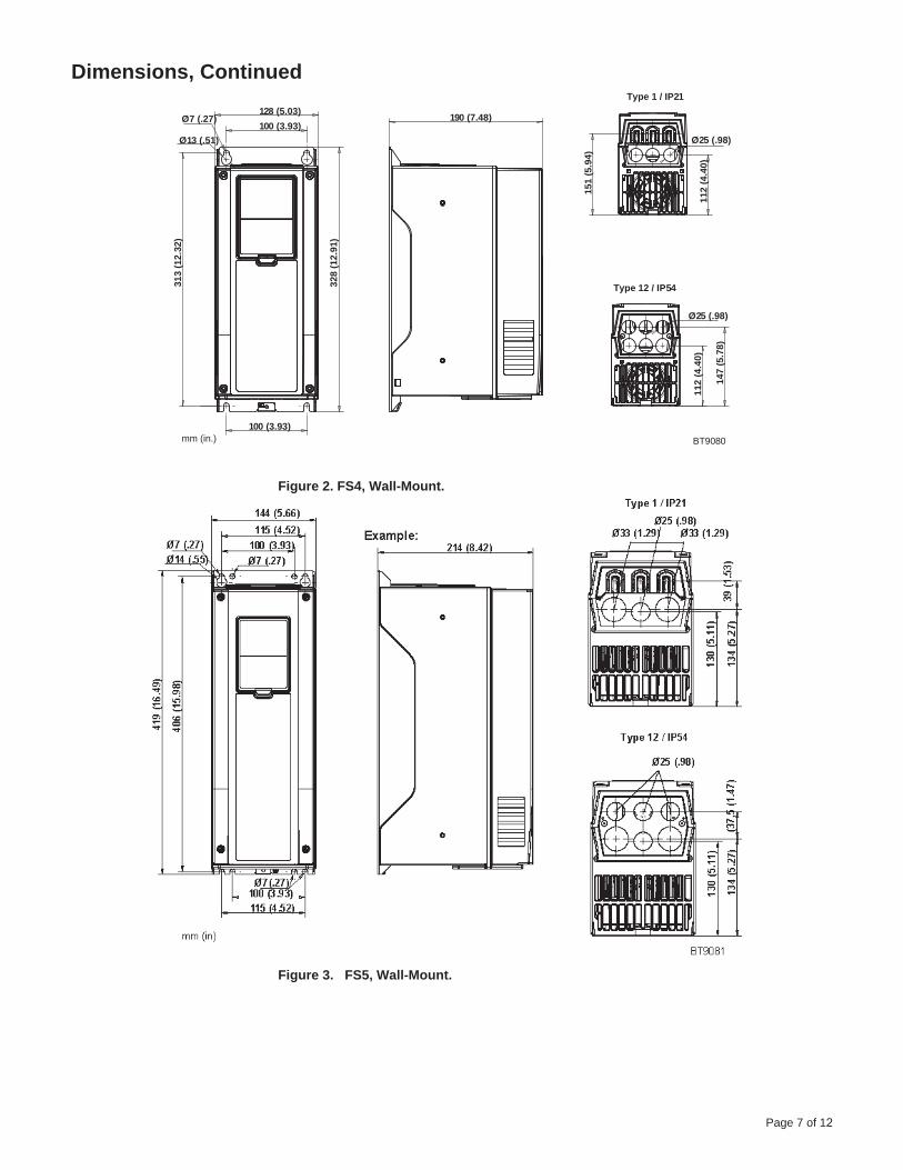
Page 7 of 12
Dimensions, Continued
128 (5.03)100 (3.93)
Ø7 (.27)
Ø13 (.51)
313
(12.
32)
100 (3.93)
328
(12.
91)
190 (7.48)
Type 1 / IP21
151
(5.9
4)
112
(4.4
0)
Type 12 / IP54
Ø25 (.98)
112
(4.4
0)
147
(5.7
8)
BT9080mm (in.)
Ø25 (.98)
Figure 2. FS4, Wall-Mount.
Figure 3. FS5, Wall-Mount.

Page 8 of 12
Dimensions, Continued 195 (7.67)148 (5.82)
Ø 15,5 (.61)Ø9 (.35)
557
(21.
92)
541
(21.
29)
Ø9 (.35) 148 (5.82)
229 (9.01)
43,7
(1.7
2)14
8(5
.82)
151
(5.9
4)
Type 1 / IP21
Ø40 (1.57)
Ø33 (1.29)
Ø40 (1.57)
42(1
.65)
148
(5.8
2)
151
(5.9
4)
Type 12 / IP54 BT9082mm (in)
Ø25 (.98) Ø25 (.98)
Figure 4. FS6, Wall-Mount.
259 (10.19)
Ø20 (.78)
660
(25.
98)
645
(25.
39)
237 (9.33)190 (7.48) Ø9 (.35)
Ø16 (.62)
Ø51 (2)
Type 1 / IP21
160
(6.2
9)21
1 (8
.30)
Type 12 / IP54
Ø25 (.98)
Ø50 (1.96)
160
(6.2
9)21
7 (8
.54)
9083bt
mm (in)
Figure 5. FS7, Wall-Mount.
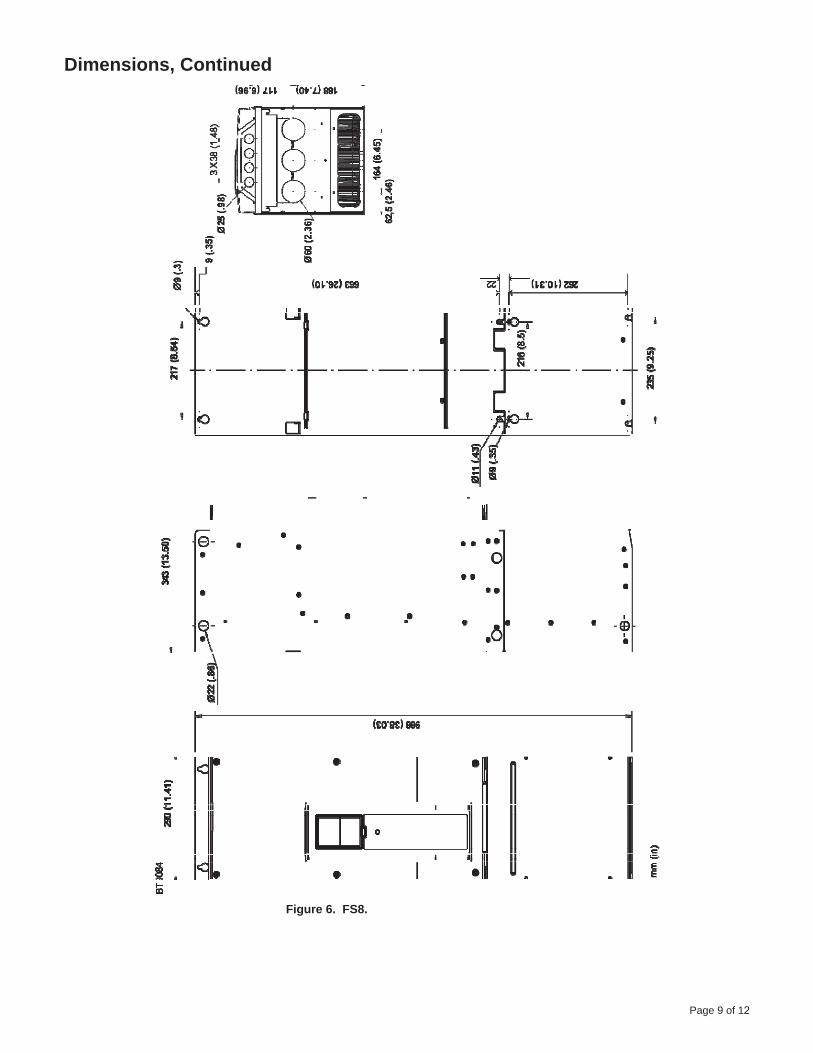
Page 9 of 12
Dimensions, Continued
Figure 6. FS8.
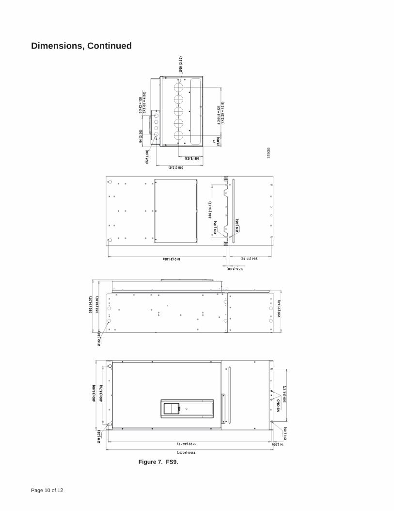
Page 10 of 12
Dimensions, Continued
Figure 7. FS9.
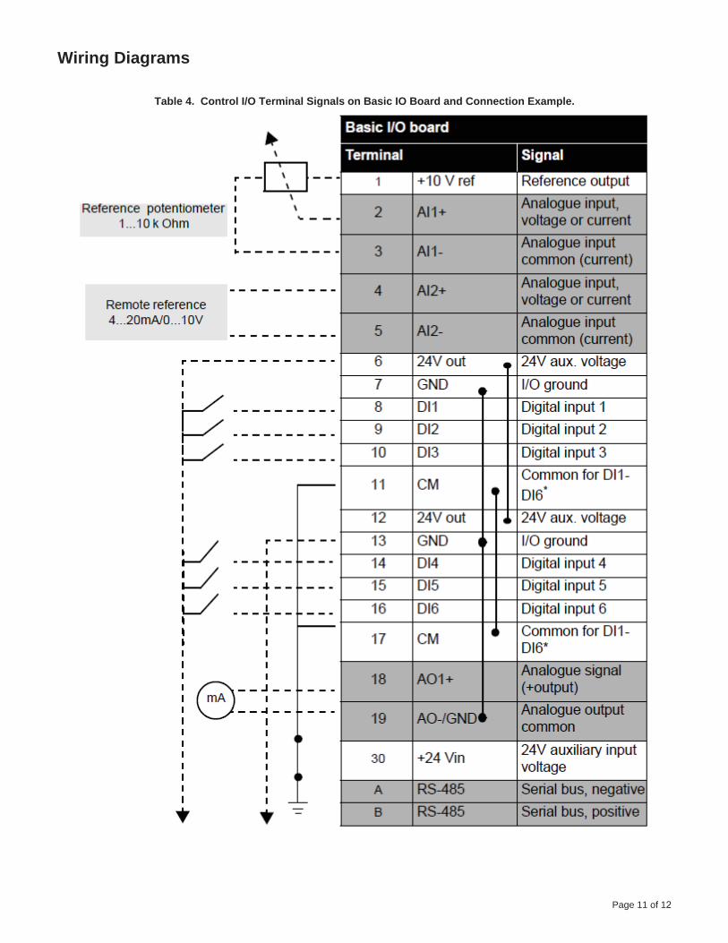
Page 11 of 12
Wiring Diagrams
Table 4. Control I/O Terminal Signals on Basic IO Board and Connection Example.

Page 12 of 12
Wiring Diagrams, Continued Table 5. Control I/O Terminal Signals on Relay Board 1 and Connection Example.
Table 6. Control I/O Terminal Signals on Relay Board 2 and Connection Example.
Figure 8. Basic Control Terminals.

Technical Specification Sheet
Page 1 of 8
PXC Compact Series
Figure 1. PXC Compact Series Controllers (PXC-24 and PXC-36 shown.)
Description
The PXC Compact Series (Programmable Controller–Compact) is a high-performance Direct Digital Control (DDC) supervisory equipment controller, which is an integral part of the APOGEE® Automation System.
The PXC Compact Series offers integrated I/O based on state-of-the-art TX-I/O™ Technology, which provides superior flexibility of point and signal types, and makes it an optimal solution for Air Handling Unit (AHU) control. The PXC Compact operates stand-alone or networked to perform complex control, monitoring, and energy management functions without relying on a higher-level processor.
The PXC Compact Series communicates with other field panels or workstations on a peer-to-peer Automation Level Network (ALN) and supports the following communication options:
Ethernet TCP/IP
P2 RS-485
The PXC Compact is available with 16, 24, or 36 point terminations. Selected models in the Compact Series provide the following options:
Support for FLN devices.
An extended temperature range for the control ofrooftop devices.
Support for Island Bus, which uses TX I/Omodules to expand the number of pointterminations.
Features
DIN rail mounted device with removable terminalblocks simplifies installation and servicing.
Proven program sequences to match equipmentcontrol applications.
Built-in energy management applications and DDCprograms for complete facility management.
Comprehensive alarm management, historicaldata trend collection, operator control, andmonitoring functions.
Sophisticated Adaptive Control, a closed loopcontrol algorithm that auto-adjusts to compensatefor load/seasonal changes.
Message control for terminals, printers, pagers,and workstations.
Highly configurable I/O using Siemens state-of-the-art TX-I/O™ Technology.
HMI RS-232 port, which provides laptopconnectivity for local operation and engineering.
Extended battery backup of Real Time Clock.
Persistent database backup and restore within thecontroller.
Optional HOA (Hand/Off/Auto) module forswappable and configurable HOA capability.
Suggested Manufacturer:Siemens Industry, Inc. or approved equal.

Optional extended temperature range for rooftopinstallation.
Optional peer-to-peer communications overindustry-standard 10Base-T/100Base-TX Ethernetnetworks.
Optional support for FLN devices.
Optional support for P1 Wireless FLN.
Optional operation as a P1 FLN device with defaultapplications.
Optional support for Virtual AEM.
PXM10T and PXM10S support: Optional LCDLocal user interface with HOA (Hand-off-auto)capability and point commanding and monitoringfeatures.
The Compact Series
In addition to building and system management functions, the Compact Series includes several styles of controllers that flexibly meet application needs.
PXC-16
The PXC-16 provides control of 16 points, including 8 software-configurable universal points.
Point count includes: 3 Universal Input (UI), 5 Universal I/O (U), 2 Digital Input (DI), 3 Analog Output (AOV), and 3 Digital Output (DO).
PXC-24
The PXC-24 provides control of 24 points, including 16 software-configurable universal points.
Point count includes: 3 Universal Input (UI), 9 Universal I/O (U), 4 Super Universal I/O (X), 3 Analog Output (AOV), 5 Digital Output (DO).
PXC-36
The PXC-36 provides control of 36 local points, including 24 software-configurable universal points.
Point count includes: 18 Universal I/O (U), 6 Super Universal I/O (X), 4 Digital Input (DI), and 8 Digital Output (DO).
The PXC-36 offers the flexibility of expanding the total point count through a self-forming island bus. With the addition of a TX-I/O Power Supply, up to 4 TX-I/O modules can be supported. For more information, see the TX-I/O Product Range Technical Specification Sheet (149-476).
Available Options
The following options are available to match the application:
Ethernet or RS-485 ALN
Support for APOGEE P2 ALN through TCP/IP or RS-485 networks.
FLN Support
The PXC-24 “F32” models support up to 32 P1FLN devices when the ALN is connected toTCP/IP.
The PXC-24 “F” models with an FLN licensesupport up to 32 P1 FLN devices when the ALN isconnected to TCP/IP.
The PXC-36 with an FLN license supports up to 96P1 FLN devices when the ALN is connected toRS-485 or TCP/IP.
A Wireless FLN may also be used to replace thetraditional P1 FLN cabling with wirelesscommunication links that form a wireless meshnetwork. Additional hardware is required toimplement the Wireless FLN.
For more information about FLN support, contact your local Siemens Industry representative.
P1 FLN Operation
The PXC-16 and PXC-24 can be configured as a programmable P1 FLN device. In the P1 FLN mode, the PXC Compact functions as an equipment controller with customized programming and default applications.
Virtual AEM Support
The Virtual AEM license allows the PXC Compact to connect an RS-485 APOGEE Automation Level Network or individual field panels to a P2 Ethernet network without additional hardware.
Extended Temperature Operation
The "R" models of the PXC Compact Series support extended temperature operation, allowing for rooftop installations.
Field Panel GO
The PXC-36 supports Field Panel GO.
The Field Panel GO license provides a Web-based user interface for your APOGEE® Building Automation System. It is an ideal solution for small or remote facilities with field panels on an Ethernet Automation Level Network (ALN).
Page 2 of 8

Page 3 of 8
Hardware
The PXC Compact Series consists of the following major components:
Input/Output Points
Power Supply
Controller Processor
Input/Output Points
The PXC Compact input/output points perform A/Dor D/A conversion, signal processing, pointcommand output, and communication with thecontroller processor. The terminal blocks areremovable for easy termination of field wiring.
The Universal and Super Universal pointsleverage TX-I/O™ Technology from SiemensIndustry to configure an extensive variety of pointtypes.
Universal Input (UI) and Universal Input/Output (U)points are software-selectable to be:
0-10V input
4-20 mA input
Digital Input
Pulse Accumulator inputs
1K Ni RTD @ 32°F (Siemens, JohnsonControls, DIN Standard)
1K Pt RTD (375 or 385 alpha) @ 32°F
10K NTC Thermistor (Type 2 and Type 3) @ 77°F
100K NTC Thermistor (Type 2) @ 77°F
0-10V Analog Output (Universal Input/Output (U) points only)
Super Universal (X) points (PXC-24 and PXC-36only) are software-selectable to be:
0-10V input
4-20 mA input
Digital Input
Pulse Accumulator inputs
1K Ni RTD @ 32°F (Siemens, JohnsonControls, DIN Standard)
1K Pt RTD (375 or 385 alpha) @ 32°F
10K NTC Thermistor (Type 2 and Type 3) @ 77°F
100K NTC Thermistor (Type 2) @ 77°F
0-10V Analog Output
4-20 mA Analog Output
Digital Output (using external relay)
Dedicated Digital Input (DI) points (PXC-16 andPXC-36 only) are dry contact status sensing.
Digital Output (DO) points are 110/220V 4 Amp(resistive) Form C relays; LEDs indicate the statusof each point.
All PXC Compact Series models support 0-10 VdcVoltage Analog Output circuits.
On PXC-24 and PXC-36 models, the SuperUniversal circuits may be defined as 4-20 mAcurrent AO.
Power Supply
The 24 volt DC power supply provides regulatedpower to the input/output points and activesensors. The power supply is internal to the PXCCompact housing, eliminating the need forexternal power supply and simplifying installationand troubleshooting.
The power supply works with the processor toensure smooth power up and power downsequences for the equipment controlled by the I/Opoints, even through brownout conditions.
Controller Processor
The PXC Compact Series includes amicroprocessor-based multi-tasking platform forprogram execution and communications with theI/O points and with other PXC Compacts and fieldpanels over the ALN.
A Human Machine Interface (HMI) port, with aquick-connect phone jack (RJ-45), uses RS-232protocol to support operator devices (such as alocal user interface or simple CRT terminal), and aphone modem for dial-in service capability.
A USB Device port supports a generic serialinterface for an HMI or Tool connection.
The program and database information stored inthe PXC Compact RAM memory is battery-backed. This eliminates the need for time-consuming program and database re-entry in theevent of an extended power failure.
The firmware, which includes the operatingsystem, is stored in non-volatile flash ROMmemory; this enables firmware upgrades in thefield.
Brownout protection and power recovery circuitryprotect the controller board from powerfluctuations.
LEDs provide instant visual indication of overalloperation, network communication, and lowbattery warning.

Page 4 of 8
Programmable Control with Application Flexibility
The PXC Compact Series of high performance controllers provides complete flexibility, which allows the owner to customize each controller with the exact program for the application.
The control program for each PXC Compact is customized to exactly match the application. Proven Powers Process Control Language (PPCL), a text-based programming structure like BASIC, provides direct digital control and energy management sequences to precisely control equipment and optimize energy usage.
Global Information Access
The HMI port supports operator devices, such as a local user interface or simple CRT terminal, and a phone modem for dial-in service capability. Devices connected to the operator terminal port gain global information access.
Multiple Operator Access
Multiple operators can access the network simultaneously. Multiple operator access ensures that alarms are reported to an alarm printer while an operator accesses information from a local terminal. When using the Ethernet TCP/IP ALN option, multiple operators may also access the controller through concurrent Telnet sessions and/or local operator terminal ports.
Menu Prompted, English Language Operator Interface
The PXC Compact field panel includes a simple, yet powerful, menu-driven English Language Operator Interface that provides, among other things:
Point monitoring and display
Point commanding
Historical trend collection and display for multiplepoints
Event scheduling
Program editing and modification via PowersProcess Control Language (PPCL)
Alarm reporting and acknowledgment
Continual display of dynamic information
Built-in Direct Digital Control Routines
The PXC Compact provides stand-alone Direct Digital Control (DDC) to deliver precise HVAC control and comprehensive information about system operation. The controller receives information from sensors in the building, processes the information, and directly controls the equipment. The following functions are available:
Adaptive Control, an auto-adjusting closed loopcontrol algorithm, which provides more efficient,adaptive, robust, fast, and stable control than thetraditional PID control algorithm. It is superior interms of response time and holding steady state,and at minimizing error, oscillations, and actuatorrepositioning.
Closed Loop Proportional, Integral and Derivative(PID) control.
Logical sequencing.
Alarm detection and reporting.
Reset schedules.
Built-in Energy Management Applications
The following applications are programmed in the PXC Compact Series and require simple parameter input for implementation:
Automatic Daylight Saving Time switchover
Calendar-based scheduling
Duty cycling
Economizer control
Equipment scheduling, optimization andsequencing
Event scheduling
Holiday scheduling
Night setback control
Peak Demand Limiting (PDL)
Start-Stop Time Optimization (SSTO)
Temperature-compensated duty cycling
Temporary schedule override
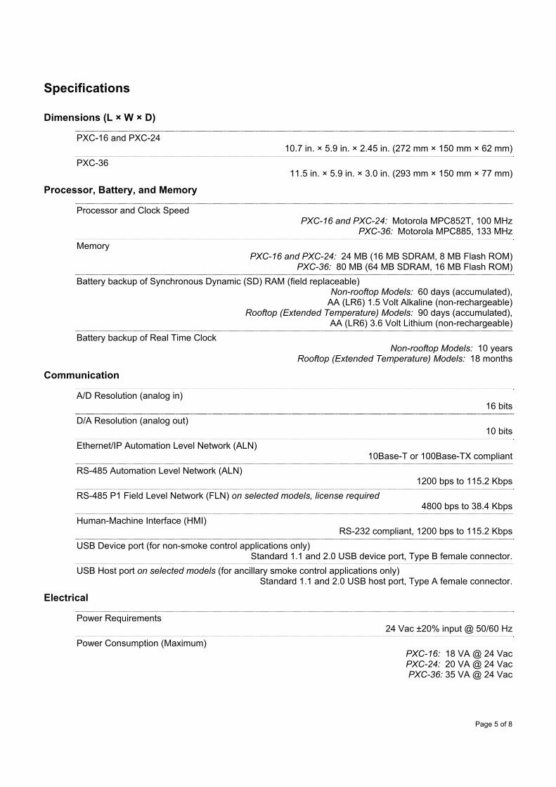
Page 5 of 8
Specifications
Dimensions (L × W × D)
PXC-16 and PXC-24 10.7 in. × 5.9 in. × 2.45 in. (272 mm × 150 mm × 62 mm)
PXC-36 11.5 in. × 5.9 in. × 3.0 in. (293 mm × 150 mm × 77 mm)
Processor, Battery, and Memory
Processor and Clock Speed PXC-16 and PXC-24: Motorola MPC852T, 100 MHz
PXC-36: Motorola MPC885, 133 MHz
Memory PXC-16 and PXC-24: 24 MB (16 MB SDRAM, 8 MB Flash ROM)
PXC-36: 80 MB (64 MB SDRAM, 16 MB Flash ROM)
Battery backup of Synchronous Dynamic (SD) RAM (field replaceable) Non-rooftop Models: 60 days (accumulated),
AA (LR6) 1.5 Volt Alkaline (non-rechargeable) Rooftop (Extended Temperature) Models: 90 days (accumulated),
AA (LR6) 3.6 Volt Lithium (non-rechargeable)
Battery backup of Real Time Clock Non-rooftop Models: 10 years
Rooftop (Extended Temperature) Models: 18 months
Communication
A/D Resolution (analog in) 16 bits
D/A Resolution (analog out) 10 bits
Ethernet/IP Automation Level Network (ALN) 10Base-T or 100Base-TX compliant
RS-485 Automation Level Network (ALN) 1200 bps to 115.2 Kbps
RS-485 P1 Field Level Network (FLN) on selected models, license required 4800 bps to 38.4 Kbps
Human-Machine Interface (HMI) RS-232 compliant, 1200 bps to 115.2 Kbps
USB Device port (for non-smoke control applications only) Standard 1.1 and 2.0 USB device port, Type B female connector.
USB Host port on selected models (for ancillary smoke control applications only) Standard 1.1 and 2.0 USB host port, Type A female connector.
Electrical
Power Requirements 24 Vac ±20% input @ 50/60 Hz
Power Consumption (Maximum) PXC-16: 18 VA @ 24 Vac PXC-24: 20 VA @ 24 Vac PXC-36: 35 VA @ 24 Vac

Page 6 of 8
AC Power and Digital Outputs NEC Class 1 Power Limited
Communication and all other I/O NEC Class 2
Digital Input Contact Closure Sensing
Dry Contact/Potential Free inputs only Does not support counter inputs
Digital Output Class 1 Relay
Analog Output 0 to 10 Vdc
Universal Input (UI) and Universal Input/Output (U) Analog Input
Voltage (0-10 Vdc) Current (4-20 mA)
1K Ni RTD @ 32°F 1K Pt RTD (375 or 385 alpha) @ 32°F
10K NTC Type 2 or Type 3 Thermistor @ 77°F 100K NTC Type 2 Thermistor @ 77°F
Digital Input Pulse Accumulator
Contact Closure Sensing Dry Contact/Potential Free inputs only
Supports counter inputs up to 20 Hz Analog Output (Universal Input/Output (U) points only)
Voltage (0-10 Vdc)
Super Universal (X) Analog Input
Voltage (0-10 Vdc) Current (4-20 mA)
1K Ni RTD @ 32°F 1K Pt RTD (375 or 385 alpha) @ 32°F
10K NTC Type 2 or Type 3 Thermistor @ 77°F 100K NTC Type 2 Thermistor @ 77°F
Digital Input Pulse Accumulator
Contact Closure Sensing Dry Contact/Potential Free inputs only
Supports counter inputs up to 20 Hz Analog Output
Voltage (0-10 Vdc) Current (4-20 mA)
Digital Output (requires an external relay) 0 to 24 Vdc, 22 mA max.
Operating Environment
Ambient operating temperature 32°F to 122°F (0°C to 50°C)
Ambient operating temperature with rooftop (extended temperature) option -40°F to 158°F (-40°C to 70°C)
Relative Humidity PXC-16 and PXC-24: 5% to 95%, non-condensing
PXC-36: 5% to 95%, non-condensing
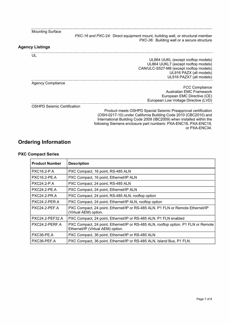
Page 7 of 8
Mounting Surface PXC-16 and PXC-24: Direct equipment mount, building wall, or structural member
PXC-36: Building wall or a secure structure
Agency Listings
UL UL864 UUKL (except rooftop models)
UL864 UUKL7 (except rooftop models) CAN/ULC-S527-M8 (except rooftop models)
UL916 PAZX (all models) UL916 PAZX7 (all models)
Agency Compliance FCC Compliance
Australian EMC Framework European EMC Directive (CE)
European Low Voltage Directive (LVD)
OSHPD Seismic Certification Product meets OSHPD Special Seismic Preapproval certification
(OSH-0217-10) under California Building Code 2010 (CBC2010) and International Building Code 2009 (IBC2009) when installed within the
following Siemens enclosure part numbers: PXA-ENC18, PXA-ENC19, or PXA-ENC34.
Ordering Information
PXC Compact Series
Product Number Description
PXC16.2-P.A PXC Compact, 16 point, RS-485 ALN
PXC16.2-PE.A PXC Compact, 16 point, Ethernet/IP ALN
PXC24.2-P.A PXC Compact, 24 point, RS-485 ALN
PXC24.2-PE.A PXC Compact, 24 point, Ethernet/IP ALN
PXC24.2-PR.A PXC Compact, 24 point, RS-485 ALN, rooftop option
PXC24.2-PER.A PXC Compact, 24 point, Ethernet/IP ALN, rooftop option
PXC24.2-PEF.A PXC Compact, 24 point, Ethernet/IP or RS-485 ALN. P1 FLN or Remote Ethernet/IP (Virtual AEM) option.
PXC24.2-PEF32.A PXC Compact, 24 point, Ethernet/IP or RS-485 ALN. P1 FLN enabled
PXC24.2-PERF.A PXC Compact, 24 point, Ethernet/IP or RS-485 ALN, rooftop option. P1 FLN or Remote Ethernet/IP (Virtual AEM) option.
PXC36-PE.A PXC Compact, 36 point, Ethernet/IP or RS-485 ALN.
PXC36-PEF.A PXC Compact, 36 point, Ethernet/IP or RS-485 ALN, Island Bus, P1 FLN.
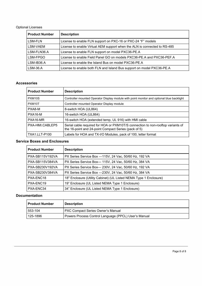
Page 8 of 8
Optional Licenses
Product Number Description
LSM-FLN License to enable FLN support on PXC-16 or PXC-24 “F” models
LSM-VAEM License to enable Virtual AEM support when the ALN is connected to RS-485
LSM-FLN36.A License to enable FLN support on model PXC36-PE.A
LSM-FPGO License to enable Field Panel GO on models PXC36-PE.A and PXC36-PEF.A
LSM-IB36.A License to enable the Island Bus on model PXC36-PE.A
LSM-36.A License to enable both FLN and Island Bus support on model PXC36-PE.A
Accessories
Product Number Description
PXM10S Controller mounted Operator Display module with point monitor and optional blue backlight
PXM10T Controller mounted Operator Display module
PXA8-M 8-switch HOA (UL864)
PXA16-M 16-switch HOA (UL864)
PXA16-MR 16-switch HOA (extended temp, UL 916) with HMI cable
PXA-HMI.CABLEP5 Serial cable required for HOA or PXM10T/S connection to non-rooftop variants of the 16-point and 24-point Compact Series (pack of 5)
TXA1.LLT-P100 Labels for HOA and TX-I/O Modules, pack of 100, letter format
Service Boxes and Enclosures
Product Number Description
PXA-SB115V192VA PX Series Service Box —115V, 24 Vac, 50/60 Hz, 192 VA
PXA-SB115V384VA PX Series Service Box— 115V, 24 Vac, 50/60 Hz, 384 VA
PXA-SB230V192VA PX Series Service Box— 230V, 24 Vac, 50/60 Hz, 192 VA
PXA-SB230V384VA PX Series Service Box —230V, 24 Vac, 50/60 Hz, 384 VA
PXA-ENC18 18" Enclosure (Utility Cabinet) (UL Listed NEMA Type 1 Enclosure)
PXA-ENC19 19” Enclosure (UL Listed NEMA Type 1 Enclosure)
PXA-ENC34 34” Enclosure (UL Listed NEMA Type 1 Enclosure)
Documentation
Product Number Description
553-104 PXC Compact Series Owner’s Manual
125-1896 Powers Process Control Language (PPCL) User’s Manual

ALARMS & INDICATION
68
ALAR
MS &
INDI
CATI
ON
2NEW!
Supply Voltage 20-31 VDC (24 VDC nominal)Current Rating StB 80 mA at 24 VDC StB-H 136 mA at 24 VACStrobe Frequency 1 HzHorn loudness 104 dB maxStrobe Intensity 15 (off-center) candela 75
(on-center) candelaoperating temperature 32° to 120°F (0° to 49°C)Dimensions 4.5"H x 4.56"W x 2.25"D
(11.43 x 11.58 x 5.72 cm)WeightStB 1.0 lb (0.45 Kg)StBH 1.1 lb (0.5 Kg)Approvals UL Listed File S3406Warranty 3 years
Supply Voltage SC110 30-120 VAC/VDC SC628 6-28 VDC SC628A, An 6-28 VAC/VDCCurrent Rating SC100 6-21 mA SC628 3-18 mA SC628An 4-30 mA SC628A 6-23 mAHorn loudness Medium, 68-80 dB
(AN model Loud, 80-95 dB)tone Continuouspanel Cutout Panel, cutout 1.13" (2.87 cm)Weight 0.1 lb (0.05 Kg)Approvals UL recognized component File# S1290Warranty 1 year
AlArm HornSC-SeRieS
DESCRIptIonThe SC Series Alarm Horns provide an audible tone when an electric signal is applied. They can be used in applications when an audible alarm is needed to indicate that immediate attention is required.
SpECIFICAtIonS
oRDERIng InFoRMAtIon
MoDEl DESCRIptIonSC110 Alarm horn, 120 VACSC628 Alarm horn, 24 VDCSC628A Alarm horn, 24 VAC/VDCSC628An Alarm horn, 24 VAC/VDC
WAll-mounted StrobeSTB, STB-H
DESCRIptIonThe Model StB and StB-H wall-mounted strobes provide a bright, eye-catching warning light for any alarm application. The StB-H features a distinct audible signal.
FEAtuRES• Wallmountedwith4"squareordouble-gangbox• Integralalarmhorn(91db)• 24VDCpowered• 15/75candelastrobeintensity• MeetsrequirementsofADA4.28.3• ULlisted• Xenonstrobeforconstantflashrate• Strobeandhornpoweredseparatelyifdesired• Jumper-selectable,continuousortemporaltone
SpECIFICAtIonS
oRDERIng InFoRMAtIon
MoDEl DESCRIptIonStB Wall-mounted strobeStB-H Wall-mounted strobe with horn
WIRIng
WIRIng
SC Horn
Horn+
–
Note: Switch 1, 2 off
Signal
++
––
S+ S+ S- H- H+
Suggested Manuafacturer:Kele Solutions or approved equal.

Industrial Pressure TransmitterComplete Offering of Ranges, Connections and Outputs
Series
626&
628
The Series 626 Pressure Transmitters possess a highly precise 0.25% full scaleaccuracy piezo-resistive sensor contained in a compact, rugged, NEMA 4X (IP66) stainlesssteel general purpose housing or cast aluminum conduit housing.
The Series 628 Pressure Transmitters are ideal for OEMs with 1% full scale accuracysensors. The transmitter is also available in the general purpose stainless steel housingand the cast aluminum conduit housing. The corrosion resistant 316L stainless steel wetted parts allow the Series 626 and 628transmitters to measure the pressure in a multitude of processes from hydraulic oils tochemicals. The Series 626 and 628 are available in ranges of vacuum, compound to 5000psi with a variety of optional outputs, process connections and electrical terminations toallow you to select the right transmitter for your application.
APPLICATIONS
• Compressors
• Pumping systems
• Irrigation equipment
• Hydraulic
• Industrial process monitoring
FEATURES
• Metal conduit housing option
• Robust 316 SS oil filled sensor
• Compact design
SPECIFICATIONS
Service: Compatible gases and liquids.
Wetted Materials: Type 316L SS.
Accuracy:
626: 0.25% F.S.;
: 0.20% RSS;
628: 1.0% F.S.;
: 0.5% RSS;
626 Absolute Ranges: 0.5% F.S.;
: 0.30% RSS.
(Includes linearity, hysteresis, and repeatability.)
Temperature Limit: 0 to 200°F (-18 to 93°C).
Compensated Temperature Range: 0 to 175°F (-18 to 79°C).
Thermal Effect: ±0.02% FS/°F (includes zero and span).
Pressure Limits: See table.
Power Requirements: 10-30 VDC (for 4-20 mA, 0-5, 1-5, 1-6 VDC outputs); 13-30
VDC (for 0-10, 2-10 VDC outputs); 5 VDC ±0.5 VDC (for 0.5-4.5 VDC ratio-metric
output).
Output Signal: 4-20 mA, 0-5 VDC,1-5 VDC, 0-10 VDC, or 0.5-4.5 VDC.
Response Time: 50 ms.
Loop Resistance: 0-1000 Ohms max. R max = 50 (Vps-10) Ohms (4-20 mA
output), 5K Ohms (0-5, 1-5, 1-6, 0-10, 2-10, 0.5-4.5 VDC output).
Stability: 1.0% FS/year (Typ.).
Current Consumption: 38 mA maximum (for 4-20 mA output); 10 mA maximum
(for 0-5, 1-5, 1-6, 0-10, 2-10, 0.5-4.5 VDC output); 140 mA maximum (for all
626/628/629-CH with optional LED).
Electrical Connections: Conduit Housing (-CH): terminal block, 1/2˝ female NPT
conduit; General Purpose Housing (-GH): cable DIN EN 175801-803-C.
Process Connection: 1/4˝ male or female NPT and BSPT.
Enclosure Rating: NEMA 4X (IP66).
Mounting Orientation: Mount in any position.
Weight: 10 oz (283 g).
Agency Approvals: CE.
General Purpose Housing (-GH)
Conduit Housing (-CH)626 with LED Display (CH housing only)
*
General Purpose Housing (-GH) with DIN C
102_Layout 2 7/24/12 9:29 AM Page 102
Suggested Manufacturer:Dwyer or approved equal.
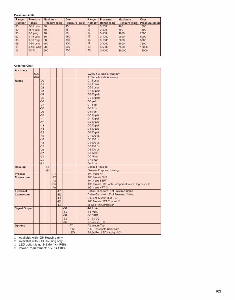
103
Range
Number
00
30
06
07
08
09
10
11
Pressure
Range
0-15 psia
15-0 psia
0-5 psig
0-15 psig
0-30 psig
0-50 psig
0-100 psig
0-150
Over
Pressure (psig)
45
45
50
150
300
300
500
750
Maximum
Pressure (psig)
30
30
10
30
60
100
200
300
Pressure Limits
Range
Number
12
13
14
15
16
18
19
26
Pressure
Range (psig)
0-200
0-300
0-500
0-1000
0-1500
0-3000
0-5000
0-8000
Over
Pressure (psig)
1000
1500
2500
5000
5000
7500
10000
12000
Maximum
Pressure (psig)
400
600
1000
2000
3000
6000
7500
10000
Ordering Chart
626
628
-00
-01
-02
-03
-04
-05
-06
-07
-08
-09
-10
-11
-12
-13
-14
-22
-15
-16
-18
-19
-26
-67
-71
-75
-81
-CH
-GH
-P1
-P2
-P3
-P5
-P9
-E1
-E3
-E4
-E5
-E6
-S1
-S2
-S4
-S5
-S7
Accuracy
Range
Housing
Process
Connection
Electrical
Connection
Signal Output
Options -AT
-NIST
-LED
j Available with -GH Housing onlyk Available with -CH Housing onlyl LED option is not NEMA 4X (IP66)m Power Requirement: 5 VDC ±10%
0.25% Full-Scale Accuracy
1.0% Full-Scale Accuracy
0-15 psia
0-30 psia
0-50 psia
0-100 psia
0-200 psia
0-300 psia
0-5 psi
0-15 psi
0-30 psi
0-50 psi
0-100 psi
0-150 psi
0-200 psi
0-300 psi
0-500 psi
0-600 psi
0-1000 psi
0-1500 psi
0-3000 psi
0-5000 psi
0-8000 psi
0-0.5 bar
0-2.5 bar
0-10 bar
0-40 bar
Conduit Housing
General Purpose Housing
1/4˝ male NPT
1/4˝ female NPT
1/4˝ male BSPT
1/4˝ female SAE with Refrigerant Valve Depressor j
1/2˝ male NPT j
Cable Gland with 3’ of Prewired Cable
Cable Gland with 9’ of Prewired Cable
DIN EN 175801-803-L j
1/2˝ female NPT Conduit k
M-12 4 Pin Connector
4-20 mA
1-5 VDC
0-5 VDC
0-10 VDC
0.5-4.5 VDC j
Aluminum Tag
NIST Traceable Certificate
Bright Red LED display kl
103_Layout 2 7/5/12 9:23 AM Page 103
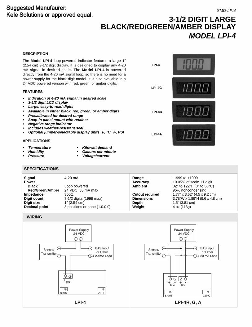
LPI-4
Power Supply24 VDC
-
+ -
+
+ -
- +
SIG
SPAN ZERO
Sensor/ Transmitter
BAS Inputor Other
4-20 mA Load
BAS Inputor Other
4-20 mA Load
LPI-4R, G, A
Power Supply24 VDC
-
+ -
+
+ -
- +
SIG+ -
B/L
SPAN ZERO
Sensor/ Transmitter
WIRING
LPI-4
Signal 4-20 mAPower
Black Loop poweredRed/Green/Amber 24 VDC, 35 mA max
Impedance 300ΩDigit count 3-1/2 digits (1999 max)Digit size 1" (2.54 cm)Decimal point 3 positions or none (1.0.0.0)
Range -1999 to +1999Accuracy ±0.05% of scale +1 digitAmbient 32° to 122°F (0° to 50°C)
95% noncondensingCutout required 1.77" x 3.62" (4.5 x 9.2 cm)Dimensions 3.78"W x 1.89"H (9.6 x 4.8 cm)Depth 1.5" (3.81 cm)Weight 4 oz (113g)
SPECIFICATIONS
LPI-4G
LPI-4R
3-1/2 DIGIT LARGEBLACK/RED/GREEN/AMBER DISPLAY
MODEL LPI-4
SMD-LPI4
LPI-4A
DESCRIPTION
The Model LPI-4 loop-powered indicator features a large 1"(2.54 cm) 3-1/2 digit display. It is designed to display any 4-20mA signal in desired scale. The Model LPI-4 is powereddirectly from the 4-20 mA signal loop, so there is no need for apower supply for the black digit model. It is also available in a24 VDC powered version with red, green, or amber digits.
FEATURES
• Indication of 4-20 mA signal in desired scale• 3-1/2 digit LCD display• Large, easy-to-read digits• Available in either black, red, green, or amber digits• Precalibrated for desired range• Snap-in panel mount with retainer• Negative range indicator• Includes weather-resistant seal• Optional jumper-selectable display units °F, °C, %, PSI
APPLICATIONS
• Temperature• Humidity• Pressure
• Kilowatt demand• Gallons per minute• Voltage/current
Suggested Manufaurer:Kele Solutions or approved equal.

19993.78 (9.6)
1.89(4.8)
1.77( 4.5)
3.62 (9.2)
PanelCutout
Mounting TabsCircuit board/Connectors
1.5(3.81)
PANEL MOUNTING INFORMATION
in(cm)
Decimal Point Jumpers Engineering Unit DisplayDecimal Jumper SelectionJ4 = 1000 No Jumper = No Unit DisplayJ5 = 1.000J6 = 10.00J7 = 100.0
Calibration JumpersIf offset (zero) is 0 or
offset (zero) is > 0 andgain (span) ÷ offset (zero) > 5
If offset (zero) is > 0 andgain (span) ÷ offset (zero) < 5
Final Adjustment Set Up1. Apply 4.00 mA, and adjust the ZERO pot for the desired low numeric display.2. Apply 20.00 mA, and adjust the SPAN pot for the desired maximum numeric display.3. Repeat steps 1 and 2 until both desired high and low readings are obtained (4-5 passes typical).
RECALIBRATION INFORMATION
LPI-4 3-1/2 Digit Black Panel DisplayLPI-4R 3-1/2 Digit Red Panel DisplayLPI-4G 3-1/2 Digit Green Panel DisplayLPI-4A 3-1/2 Digit Amber Panel Display
Specify scale, range, and decimal location when ordering.Aluminum engineering units plate will be provided upon request at no charge (2.00" x 0.75" tag with 0.125" letters).
Available plates are % RH, AMPS, DEG C., DEG F., GPM, x10 GPM, KW, KWH, PSIG, and "W.C.
ORDERING INFORMATION
J3 J2 J1
J3 J2 J1
%PSI
F
C