Embed Size (px)
Citation preview
Section G - Engine
Hosted and optimised by www.TheTVRSite.com
contents
· · · · · · · · · · .. · ·· · · · · .. ······· ··· ·11·········· · · ·· · · ·· · ··· ..... . . . . . .
Engine Set up
······ .. ····· . . .. · .. ··· .... . . 0· .. · .. · .. · .. · ...... · · ·· ...... ·· .. · . . ··
Crank Sensor
· · · · · · · · ··············· · · · · · · · .. · · · · · ·IiI·········· .. · · · · · . . . . . . . ............. .
Tappets
· · .. . . . ..... · .... ·· .. · · .. m . . . . · ........ .... · .. ·· · · . . . . . . · ·
Spark Plugs
. . . . ...... ·· ........ · .... · ... . ....... . IJ .......... · ......... ............. · .. ..
Oil Filter
· .. · · · ······· ·························IJ·· ·············· ....... .............. .
Air Filter
······················ ················CiI······ · ······ .. · ..................... .
Oil Pressure Switch
Hosted and optimised by www.TheTVRSite.com
'HIV ------- ------ -- - - -- - - - -
Service / Workshop Manual
Engine Setup -Lap Top Instructions
-\
Hosted and optimised by www.TheTVRSite.com

ServiceIWorkshop Manual -Engine Setup
2
ServiceIWorkshop Manual -Engine Setup
3
ServiceIWorkshop Manual -Engine Setup
4
ServiceIWorkshop Manual -Engine Setup
Remove the 2 x M4 alien bolts that hold the top trim panel in place.
Remove both air intake pipes.
Remove all 5 M6 x 15 allen bolts on the throttle assembly that releases the air boxes.
Remembering to remove the Air pressure . sensor pipe on the NjS air box when removing.
'\ I
)
Hosted and optimised by www.TheTVRSite.com
CERBERA SERVICEI-WORKSHOP MANUAL
5
Service/Workshop Manual -Engine Setup
6
Service/Workshop Manual -Engine Setup
7
Service/Workshop Manual -Engine Setup
8
Service/Workshop Manual -Engine Setup
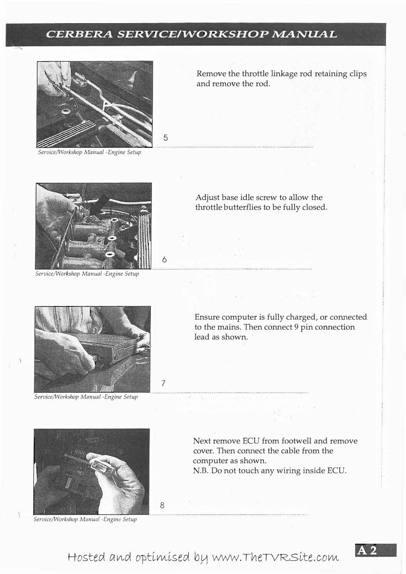
Remove the throttle linkage rod retaining clips and remove the rod.
Adjust base idle screw to allow the throttle butterflies to be fully closed.
Ensure computer is fully charged, or cOlU1ected to the mains. Then COlU1ect 9 pin cOlU1ection lead as shown.
Next remove ECU from footwell and remove cover. Then colU1ect the cable from the computer as shown. N.B. Do not touch any wiring inside ECU.
Hosted and optimised by www.TheTVRSite.com
ft41 --------------== ===---= - --------- -- --- - -
ServiceIWorkshop Manual -Engine Setup
ServiceIWorkshop Manual -Engine Setup
ServiceIWorkshop Manual -Engine Setup
ServiceIWorkshop Manual -Engine Setup
9
10
1 1
12
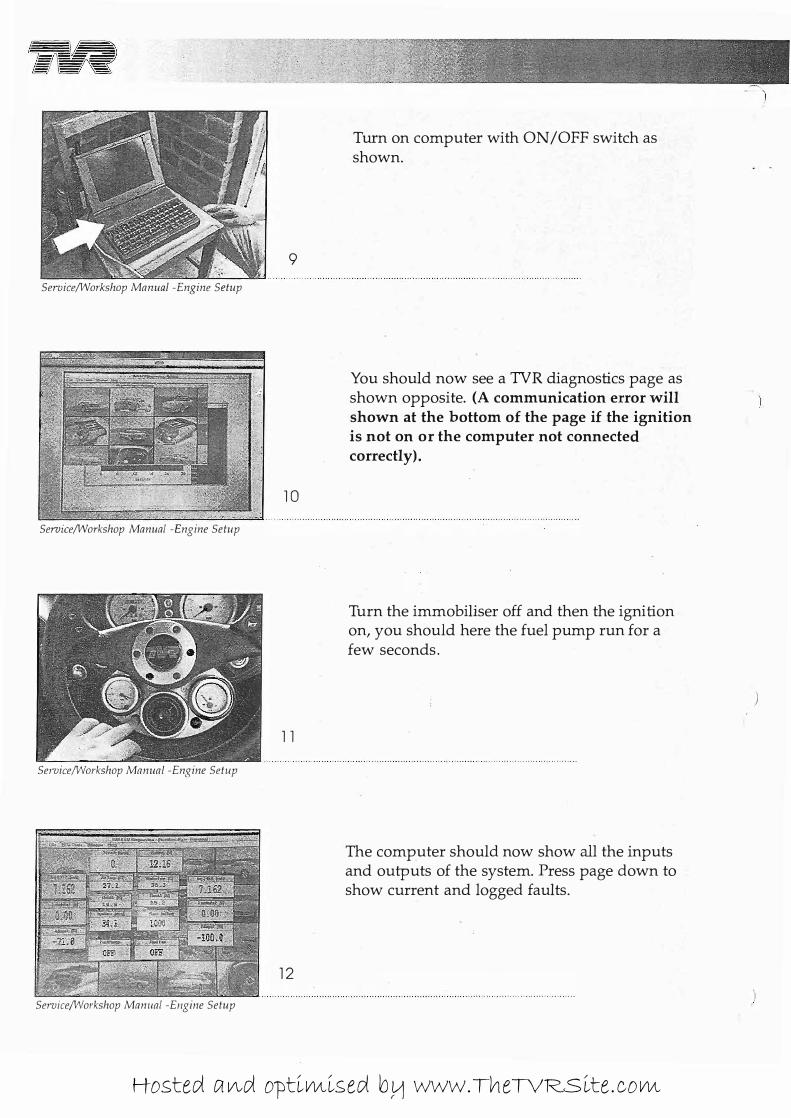
Turn on computer with ON/OFF switch as shown.
You should now see a TVR diagnostics page as shown opposite. (A communication error will shown at the bottom of the page if the ignition is not on or the computer not connected correctly).
Turn the immobiliser off and then the ignition on, you should here the fuel pump run for a few seconds.
The computer should now show all the inputs and outputs of the system. Press page down to show current and logged faults.
. )
)
)
Hosted and optimised by www.TheTVRSite.com
CERBERA SERVlCEI"WORKSHOP �NUA.L
'" .
13
Service/Workshop Manual -Engine Setup
14
Service/Workshop Manual -Engine Setup
15
Service/Workshop Manual -Engine Setup
16
Service/Workshop Manual -Engine Setup
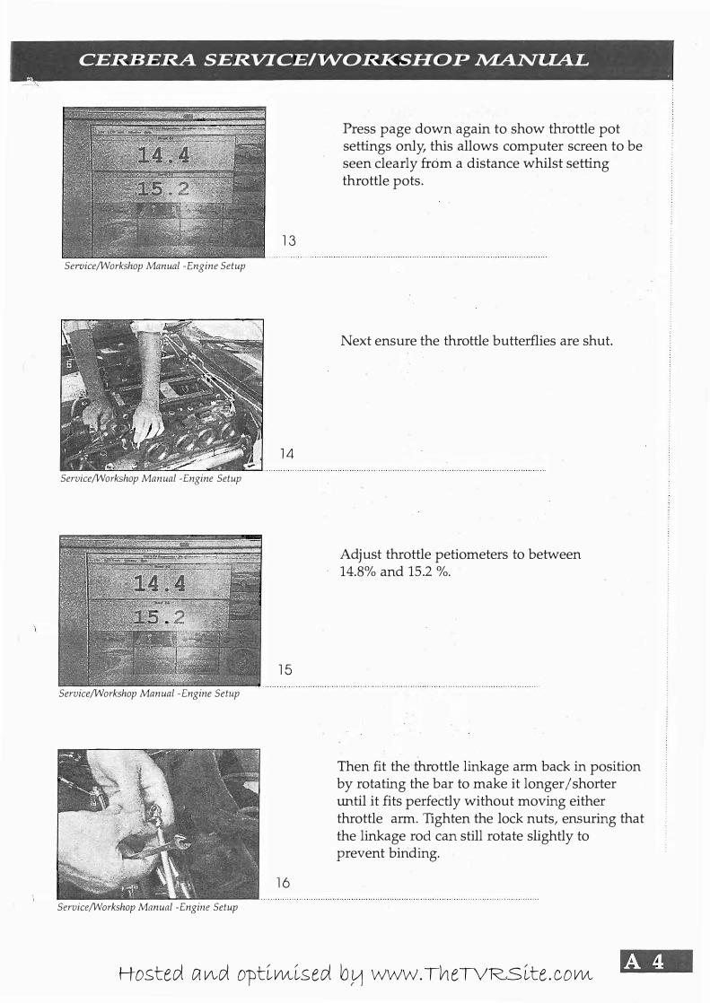
Press page down again to show throttle pot settings only, this allows computer screen to be seen clearly from a distance whilst setting throttle pots.
Next ensure the throttle butterflies are shut.
Adjust throttle petiometers to between 14.8% and 15.2 %.
Then fit the throttle linkage arm back in position by rotating the bar to make it longer/shorter until it fits perfectly without moving either throttle arm. Tighten the lock nuts, ensuring that the linkage rod can still rotate slightly to prevent binding.
Hosted and optimised by www.TheTVRSite.com
�R --=-=.=-=:= -------- -- --- - -
Service/Workshop Manual -Engine Setup
Service/Workshop Manual -Engine Setup
17
18
=5�§ 19
:: • • H . . . . . . . . . ... . . Service/Wol'kshop Manual -Engine Setup
20
Service/Wol'kshop Manual -Engine Setup
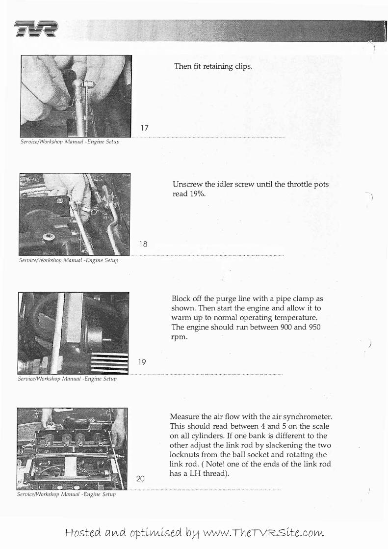
Then fit retaining clips.
Unscrew the idler screw until the throttle pots read 19%.
Block off the purge line with a pipe clamp as shown. Then start the engine and allow it to warm up to normal operating temperature. The engine should run between 900 and 950 rpm.
Measure the air flow with the air synchrometer. This should read between 4 and 5 on the scale on all cylinders. If one bank is different to the other adjust the link rod by slackening the two locknuts from the ball socket and rotating the link rod. (Note! one of the ends of the link rod has a LH thread).
)
Hosted and optimised by www.TheTVRSite.com
CERBERA SERVlCEI"WORKSHOP �NUAL
2 1
Service/Workshop Manual -Engine Setup
22
Service/Workshop Manual -Engine Setup
23
Service/Workshop Manual -Engine Setup
24
Service/Workshop Manual -Engine Setup
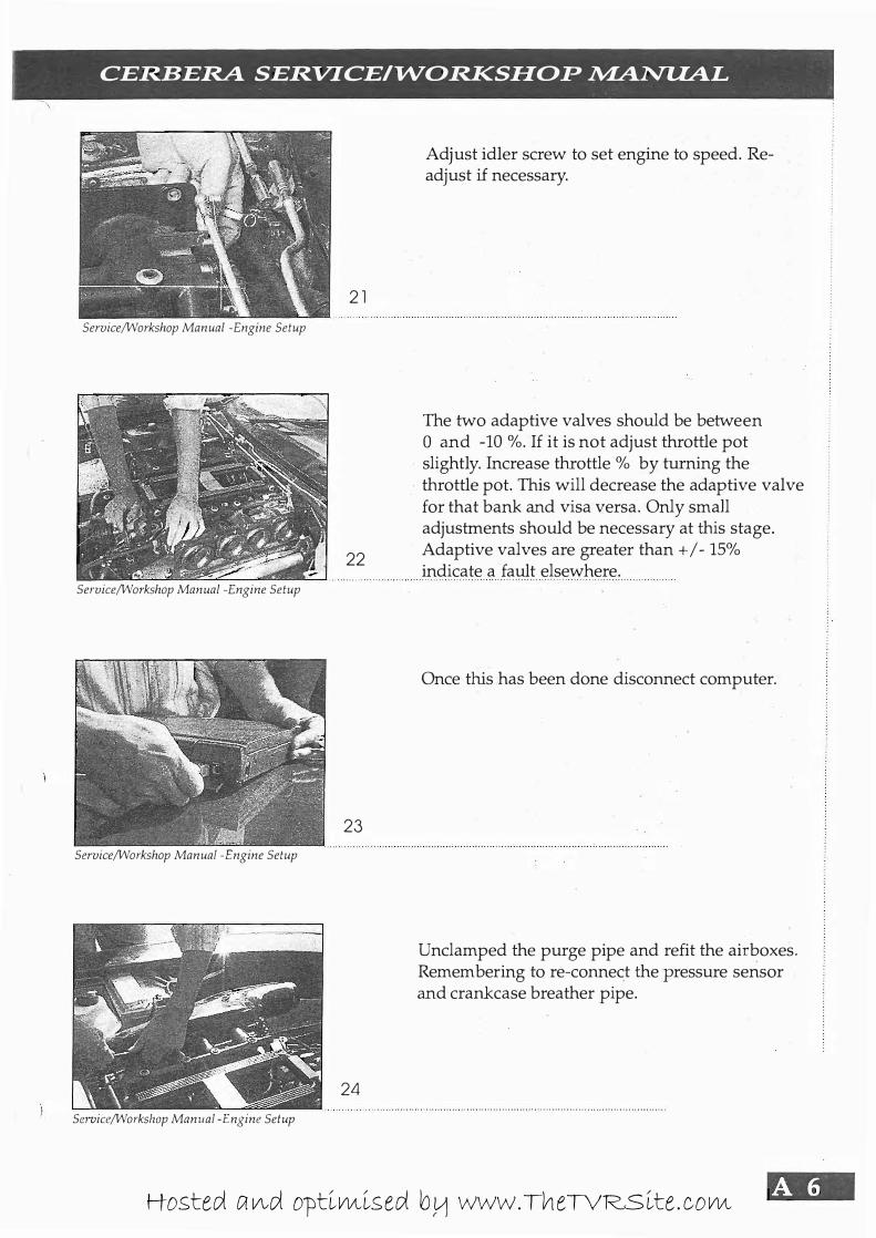
Adjust idler screw to set engine to speed. Readjust if necessary.
The two adaptive valves should be between o and -10 %. If it is not adjust throttle pot slightly. Increase throttle % by turning the throttle pot. This will decrease the adaptive valve for that bank and visa versa. Only small adjustments should be necessary at this stage. Adaptive valves are greater than + / - 15% indicate a fault elsewhere.
Once this has been done disconnect computer.
Unclamped the purge pipe and refit the airboxes. Remembering to re-connect the pressure sensor and crankcase breather pipe.
'iM .• Hosted and optimised by www.TheTVRSite.com

,.::l - ----- ---
== ==== �
Service/Workshop Manual -Engine Setup
ServiCe/Workshop Manual -Engine Setup
25
Refit the Air pipes.
And finally refit top engine cover, remembering to connect the washer pipes.
Hosted and optimised by www.TheTVRSite.com

CERBERA SERVICEI-WORKSHOP NIANUAL
Notes
Hosted and optimised by www.TheTVRSite.com
� -------
---- - - -
- - - -- - -
Service / Workshop Manual
Crank Sensor
Hosted and optimised by www.TheTVRSite.com
B\QI ==== -===..
== ===--== - --------- -- --- - -
Service/Workshop Manual -Crank Sensor
Service/Workshop ManuaL -Crank Sensor
Sel-uice/Workshop Manual -Crank Sensor
Service/Workshop ManuaL -Crank Sensor
2
3
4
, {. �';- -
_ �,c�,.�_
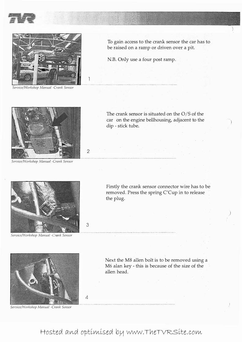
To gain access to the crank sensor the car has to be raised on a ramp or driven over a pit.
N.B. Only use a four post ramp.
The crank sensor is situated on the O/S of the car on the engine beilhousing, adjacent to the dip - stick tube.
Firstly the crank sensor connector wire has to be removed. Press the spring C'Cup in to release the plug.
Next the M8 alIen bolt is to be removed using a M6 alan key - this is because of the· size of the alien head.
Hosted and optimised by www.TheTVRSite.com
I
CERBERA SERVICEI-WORKSHOP �NUAL
5
Service/Workshop Manual -Crank Sensor
6
Service/Workshop Manual -Crank Sensor
7
Service/Workshop Manual -Crank Sensor
8
Service/Workshop Manual -Crank Sensor
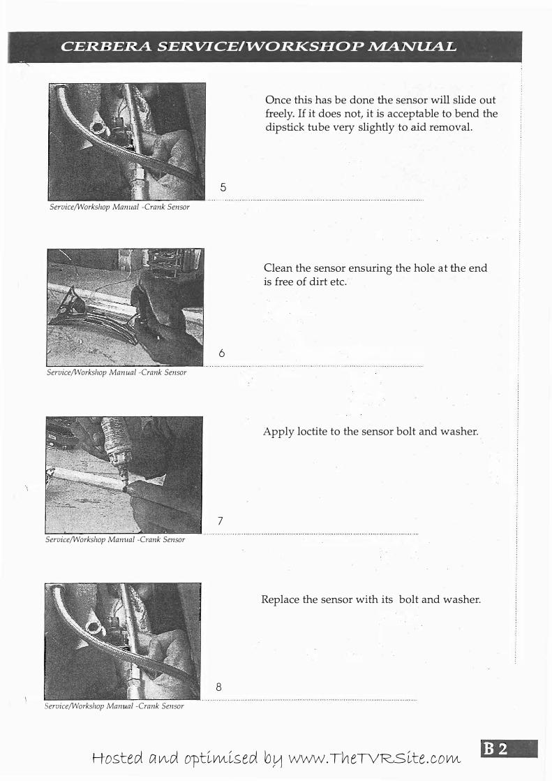
Once this has be done the sensor will slide out freely. If it does not, it is acceptable to bend the dipstick tube very slightly to aid removal.
Clean the sensor ensuring the hole at the end is free of dirt etc�
Apply loctite to the sensor bolt and washer.
Replace the sensor with its bolt and washer.
B2 Hosted and optimised by www.TheTVRSite.com
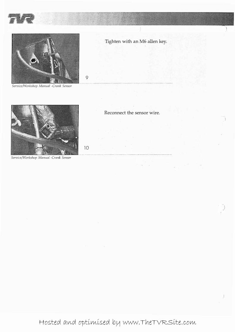
Tighten with an M6 alien key.
9
SeruiceIWorkshop Manual -Crank Sensor
Reconnect the sensor wire. .' -I
)
10
SeruiceIWorkshop Manual -Crank Sensor
)
Hosted and optimised by www.TheTVRSite.com

:
, CERBERA SERVICEI"WORKSHOP �NUAL I I
Notes
Hosted and optimised by www.TheTVRSite.com
. �
fiR ----------- - - - -- - - - -- - - - -
Service / Workshop Manual
Tappets
Hosted and optimised by www.TheTVRSite.com
5\IB' - -
-- --- --- -- - -- - -
ServiceIWorkshop Manual - Tappets
Service/Workshop Manual - Tappets
ServicelVvorkshop Manual - Tappets
Service/Workshop Manual - Tappets
2
3
4
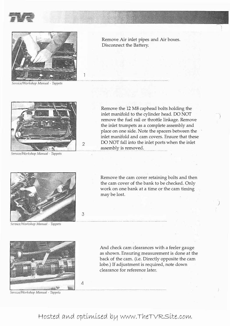
Remove Air inlet pipes and Air boxes. Disconnect the Battery.
Remove the 12 M8 caphead bolts holding the inlet manifold to the cylinder head. DO NOT remove the fuel rail or throttle linkage. Remove the inlet trumpets as a complete assembly and place on one side. Note the spacers between the inlet manifold and cam covers. Ensure that these DO NOT fall into the inlet ports when the inlet
. c:lss.��b.�yis.r.���y.�.d.:: . . . . . . . . . . . . . . . . . .
Remove the cam cover retaining bolts and then the cam cover of the bank to be checked. Only work on one bank at a time or the cam timing may be lost.
And check cam clearances with a feeler gauge as shown. Ensuring measurement is done at the back of the cam. (i.e. Directly opposite the cam lobe.) If adjustment is required, note down clearance for reference later.
)
Hosted and optimised by www.TheTVRSite.com
: CERBERA SERVICEI"WORKSHOP �NUAL
5
Service/Workshop Manual - Tappets
6
Service/Workshop Manual - Tappets
7
Service/Workshop Manual - Tappets
8
Service/Workshop Manual - Tappets
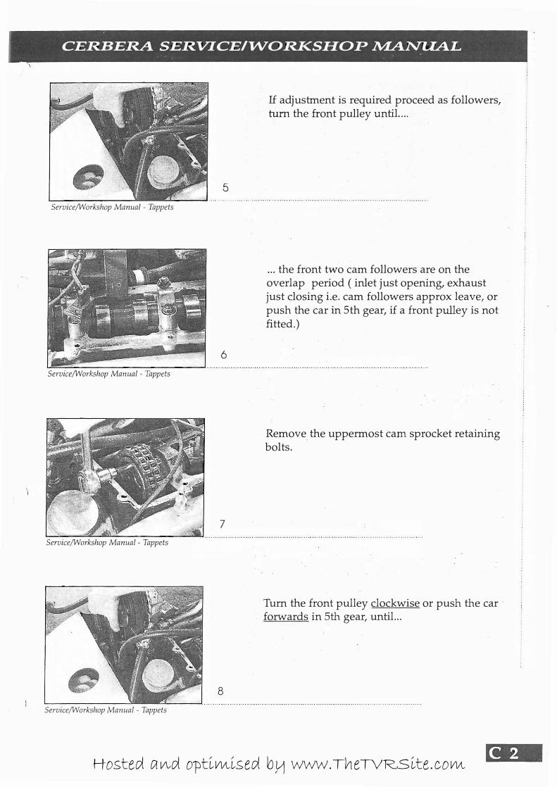
If adjustment is required proceed as followers, turn the front pulley until ....
... the front two cam followers are on the overlap period ( inlet just opening, exhaust just closing i.e. cam followers approx leave, or push the car in 5th gear, if a front pulley is not fitted.)
Remove the uppermost cam sprocket retaining bolts.
Turn the front pulley clockwise or push the car forwards in 5th gear, until...
Hosted and optimised by www.TheTVRSite.com
9
Service/Workshop Manual - Tappets
10
Sel'vice/Workshop Manual - Tappets
1 1
Sel'vice/Workshop Manual - Tappets
12
Service/Workshop Manual - Tappets
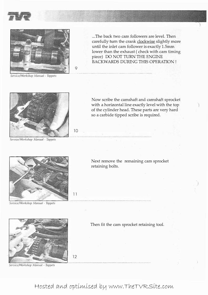
... The back two cam followers are level. Then carefully turn the crank clockwise slightly more until the inlet cam follower is exactly 1.5mm lower than the exhaust ( check with cam timing piece) DO NOT TURN THE ENGINE BACKWARDS DURING THIS OPERATION!
Now scribe the camshaft and camshaft sprocket with a horizontal line exactly level with the top of the cylinder head. These parts are very hard so a carbide tipped scribe is required.
Next remove the remaining cam sprocket retaining bolts.
Then fit the cam sprocket retaining tool.
)
Hosted and optimised by www.TheTVRSite.com
)
CERBERA SERVICEIW-ORKSHOP MANUAL
13
Service/Workshop Manual - Tappets
14
Service/Workshop Manual - Tappets
15
16
Service/Workshop Manual - Tappets
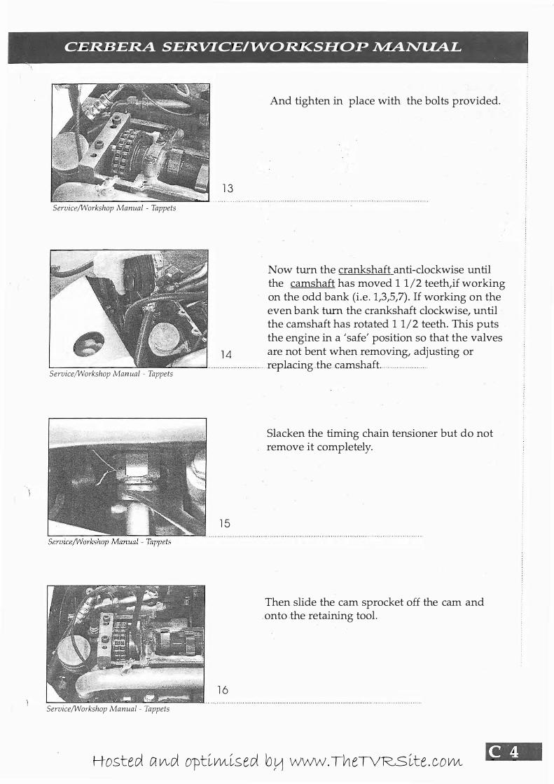
And tighten in place with the bolts provided.
Now turn the crankshaft anti-clockwise until the camshaft has moved 11 /2 teeth,if working on the odd bank (i.e. 1,3,5,7). If working on the even bank turn the crankshaft clockwise, until
the camshaft has rotated 11/2 teeth. This puts the engine in a 'safe' position so that the valves are not bent when removing, adjusting or
... replacing .. the .. camshaft. ...
Slacken the timing chain tensioner but do not remove it completely.
Then slide the cam sprocket off the cam and onto the retaining tool.
Hosted and optimised by www.TheTVRSite.com
RV -=== -===..
== =.=:� - - ---- - --- --- --- - - ... . ,'
17
L..-__ ______ ___ �::::ao..� . . . . . . . . . . . . . . . . . . . . . . .
Service/Workshop Manual - Tappets
18
Service/Workshop Manual - Tappets
19
Service/Workshop Manual - Tappets
20
Service/Workshop Manunl - Tnppets
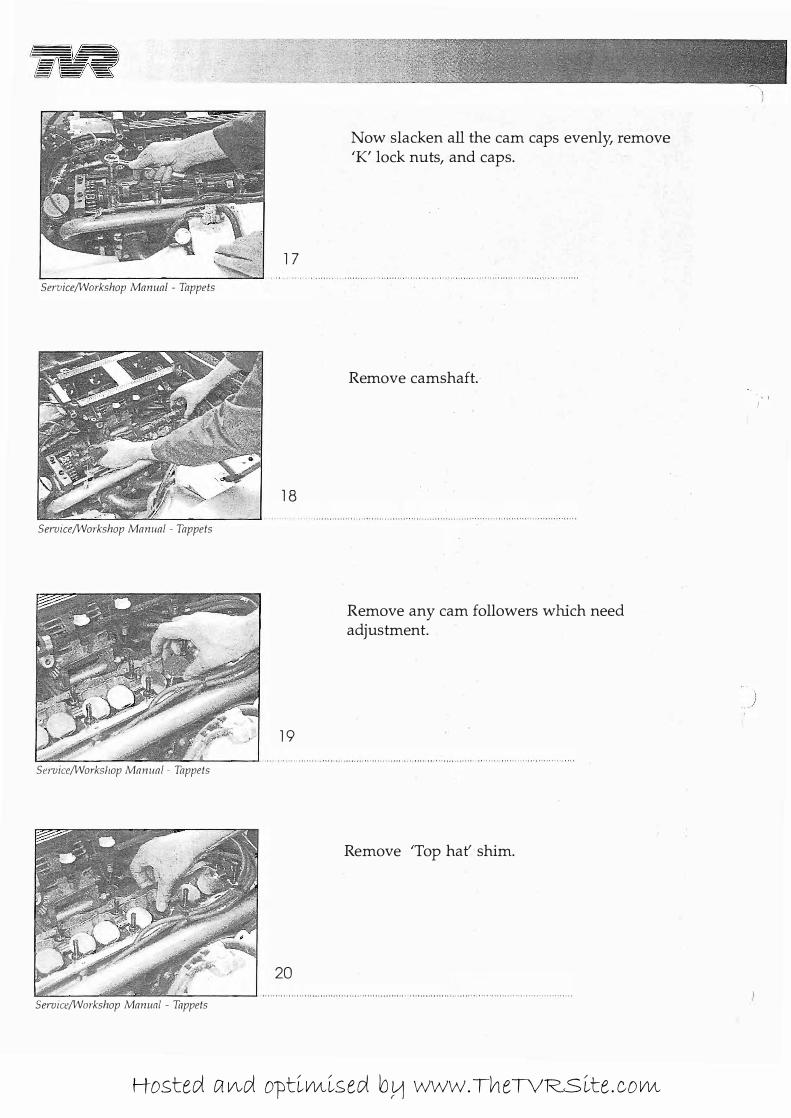
Now slacken all the cam caps evenly, remove 'K' lock nuts, and caps.
Remove camshaft.·
Remove any cam followers which need adjustment.
Remove 'Top hat' shim.
Hosted and optimised by www.TheTVRSite.com
I
\
CERBERA SERVICEIW"ORKSHOP lVlANUAL
2 1
Service/Workshop Manual - Tappets
22
Service/Workshop Manual - Tappets
23
Service/Workshop Manual - Tappets
24
Service/Workshop Manual - Tappets
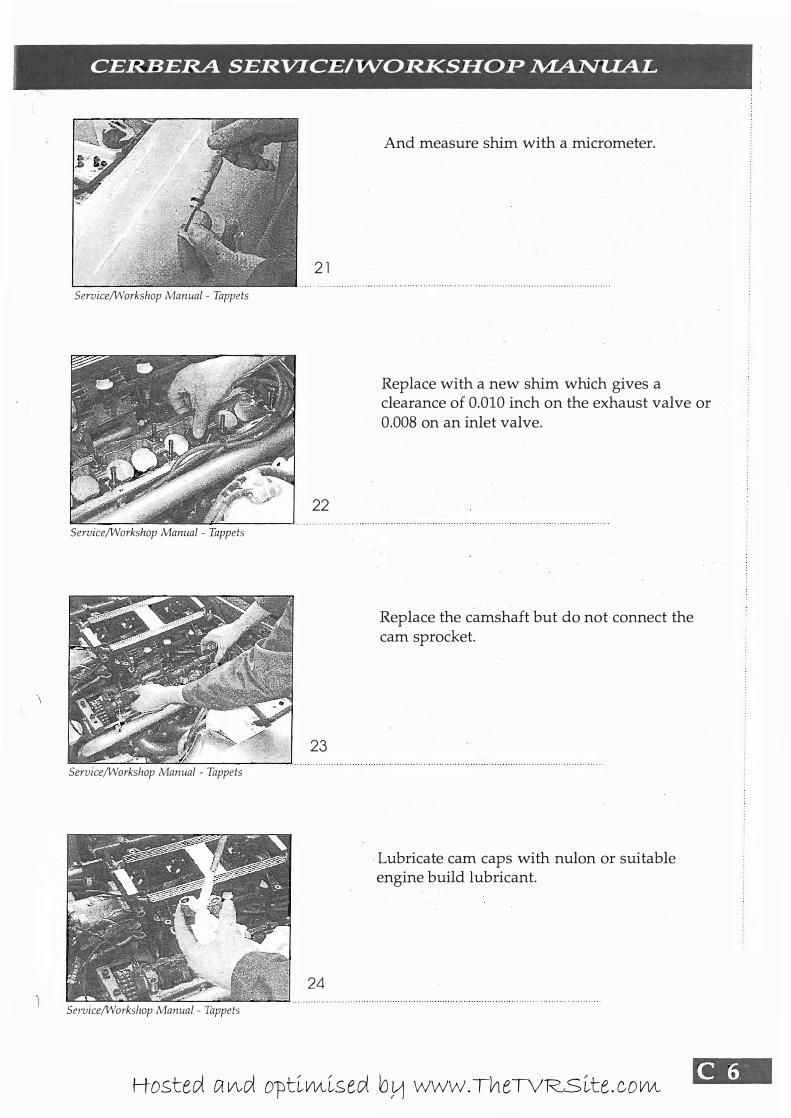
And measure shim with a micrometer.
Replace with a new shim which gives a clearance of 0 .010 inch on the exhaust valve or 0.008 on an inlet valve.
Replace the camshaft but do not connect the cam sprocket.
Lubricate cam caps with nulon or suitable engine build lubricant.
[W .• Hosted and optimised by www.TheTVRSite.com

717\1 --------------
== ===--== - --------- -== =- '=-
Service/V'lorkshop Manual - Tappets
Service/V'lorkshop Manual - Tappets
Service/V'lorkshop Manual - Tappets
Service/V'lorkshop Manual - Tappets
25
26
27
28
Replace caps and tighten progressively toward the back of the engine, note cam position whilst fitting caps.
Apply engine oil to camshaft and cam followers.
The camshaft may be rotated whilst the engine is in the 'safe' position in order to check the valve clearances DO NOT rotate the crankshaft or valve damage will occur. Repeat steps 17 to 25 until clearances are correct.
When adjustment is completed torque caps to 17lb ft. .
)
Hosted and optimised by www.TheTVRSite.com

!
I CERBERA SERVlCEI"WORKSHOP .MANUAL
29
Seroice/Workshop Manual - Tappets
30
Seroice/Workshop Manual - Tappets
31
32
Service/Workshop Manual - Tappets
Turn cam until scribe marks line up with cylinderhead and ...
... slide cam sprocket on to camshaft.
Now turn the crankshaft until the scribe lines match exactly on the cam and sprocket, now remove the sprocket retaining tool. Degrease cam sprocket retaining bolts with solvent, apply loctite thread locking compound and refit bolts, torqueing to 20 lb ft.
Loctite cam chain tensioner bolt. Tighten and secure with lockwire.
Hosted and optimised by www.TheTVRSite.com
5%1 --------------=====� - ----- --- - -- --- - -
Service/Workshop ManuaL - Tappets
Service/Workshop Manual - Tappets
Service/Workshop Manual - Tappets
Service/Workshop Manual - Tappets
33
34
35
36
' .. ��;:�t�tt��!�?:��: ::::;: '�::>," ". ' .
. . �;",it��¥!-,�� "t", �' ,"" :,' ' . .. ... .
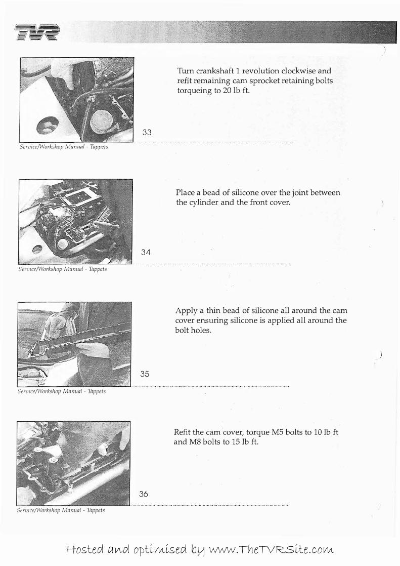
Turn crankshaft 1 revolution clockwise and refit remaining cani. sprocket retaining bolts torqueing to 20 Ib ft.
Place a bead of silicone over the joint between the cylinder and the front cover.
Apply a thin bead of silicone all around the cam cover ensuring silicone is applied all around the bolt holes.
Refit the cam cover, torque MS bolts to 10 lb ft and M8 bolts to 15 Ib ft.
)
Hosted and optimised by www.TheTVRSite.com
i
: CERBERA SERVICEI"WORKSHOP NIANUAL i
�\
Service/Workshop Manual - Tappets
Service/Workshop Manual - Tappets
37
38 -_ . .. . ........ ........... ..
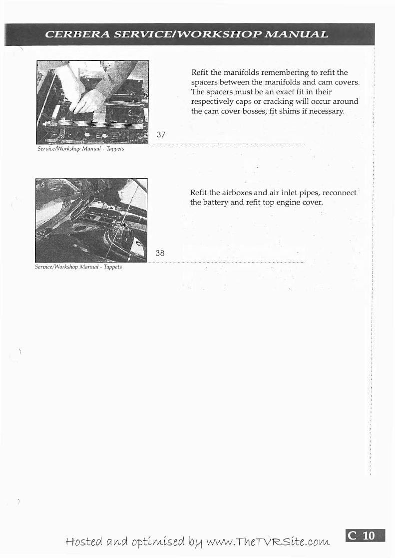
Refit the manifolds remembering to refit the spacers between the manifolds and cam covers. The spacers must be an exact fit in their respectively caps or cracking will occur around the cam cover bosses, fit shims if necessary.
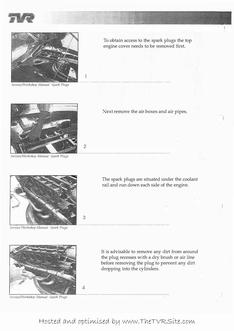
Refit the airboxes and air inlet pipes, reconnect'
the battery and refit top engine cover.
[Mnll Hosted and optimised by www.TheTVRSite.com

»R ----- ------- -- --- - -
�_r ._�,-, �-..", � -=---,�� ,� .�1
(?� �=--"eli'''. : . ·.:f.r
Service / Workshop Manual
Spark Plugs
Hosted and optimised by www.TheTVRSite.com
all -- --- - - -- ---- -
== =.:=--== - --------- -- --- - -
Service/Workshop Manual -Spark Plugs
Sel7Jice/Workshop Manual -Spark Plugs
Service/'vVorkshop Manual -Spark Plugs
Service/Workshop Manual -Spark Plugs
2
3
4
To obtain access to the spark plugs the top engine cover needs to be removed first.
Next remove the air boxes and air pipes.
The spark plugs are situated under the coolant rail and run down each side of the engine.
It is advisable to remove any dirt from around the plug recesses with a dry brush or air line before removing the plug to prevent any dirt dropping into the cylinders.
)
Hosted and optimised by www.TheTVRSite.com
I
I CERBERA SERVICEI"WORKSHOP �NUAL ,
Service/Workshop Manual -Spark Plugs
Service/Workshop Manual -Spark Plugs
\
Service/Workshop Manual -Spark Plugs
Service/Workshop Manual -Spark Plugs
5
6
7
8
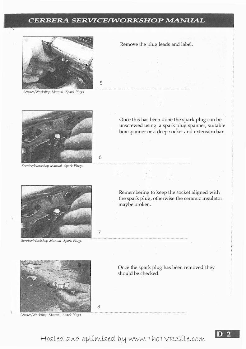
Remove the plug leads and label.
Once this has been done the spark plug can be unscrewed using a spark plug spanner, suitable box spanner or a deep socket and extension bar.
Remembering to keep the socket aligned with the spark plug, otherwise the ceramic insulator maybe broken.
Once the spark plug has been removed they should be checked.
.1". Hosted and optimised by www.TheTVRSite.com
B\41 ----------- ---
=: ===--== - -------- --- --- - -
Service/Workshop Manual -Spark Plugs
Service/Workshop Manual -Spark Plugs
Service/Worksi1op Manual -Spark Plugs
Service/Workshop Manual -Spark Plugs
10
1 1
12
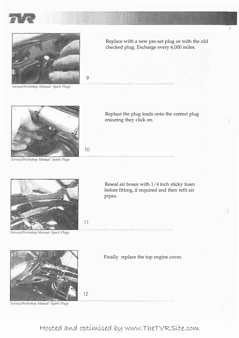
Replace with a new pre-set plug or with the old checked plug. Excharge every 6,000 miles.
Replace the plug leads onto the correct plug ensuring they click on.
Reseal air boxes with 1/4 inch sticky foam before fitting, if required and then refit air pipes.
Finally replace the top engine cover.
)
Hosted and optimised by www.TheTVRSite.com

I CERBERA SERVICEI"WORKSHOP �NUAL I
( "
Notes
11'. Hosted and optimised by www.TheTVRSite.com

.�
fiR -------
----- -
- --- - -
Service I Workshop Manual
Oil Filter
Hosted and optimised by www.TheTVRSite.com
D\$I --------- -== - ----------- - -- - -
Service/Workshop Manual -Oil Filter.
Service/Workshop Manual -Oil Filter.
Service/Workshop Manual -Oil Filter.
Service/Workshop Manual -Oil Filter.
2
3
4
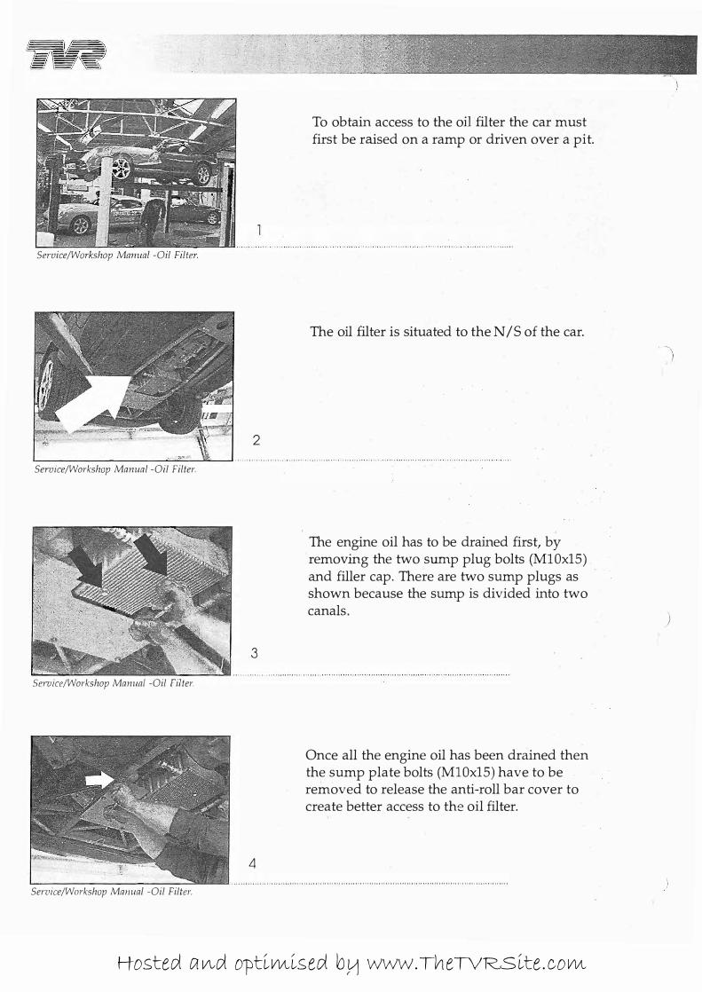
To obtain access to the oil filter the car must first be raised on a ramp or driven over a pit.
The oil filter is situated to the N /S of the car.
The engine oil has to be drained first, by removing the two sump plug bolts (MIOx15) . and filler cap. There are two sump plugs as shown because the sump is divided into two canals.
Once all the engine oil has been drained then the sump plate bolts (MIOx15) have to be removed to release the anti-roll bar cover to create better access to the oil filter.
)
Hosted and optimised by www.TheTVRSite.com
CERBERA SERVlCEI"WORKSHOP �NUAL
5
Service/Workshop Manual -Oil Filter.
6
Service/Workshop Manual -Oil Filter.
7
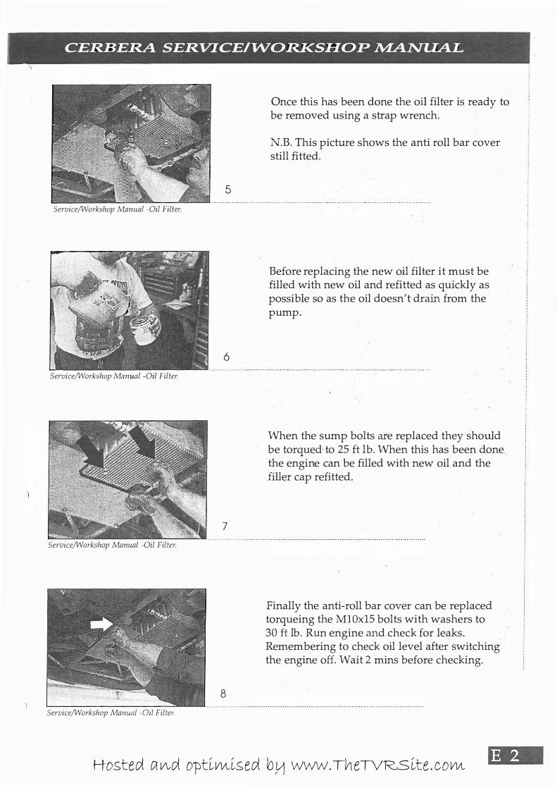
Once this has been done the oil filter is ready to be removed using a strap wrench.
N.B. This picture shows the anti roll bar cover still fitted.
Before replacing the new oil filter it must be filled with new oil and refitted as quickly as possible so as the oil doesn't drain from the pump.
When the sump bolts are replaced they should be torqued to 25 ft lb. When this has been done . the engine can be filled with new oil and the ..filler cap refitted.
....... ---'-�-- .............................. ..
Service/Workshop Manual -Oil Filter.
Service/Workshop Manual -Oil Filter.
8
Finally the anti-roll bar cover can be replaced torqueing the MIOx15 bolts with washers to 30ft lb. RUn engine and check for leaks. Remembering to check oil level after switching the engine off. Wait 2 mins before checking.
Hosted and optimised by www.TheTVRSite.com

� --- - -
-- -- -
-- -
-
-- - - -
-- - -
- - -
Service / Workshop Manual
Air Filter
Hosted and optimised by www.TheTVRSite.com
." -- ---- ---- --== ===----:= -------- -- --- - -
Service/Workshop Manual -Air Filter.
Seroice/Workshop Manual - Air Filter.
Service/lNorkshop Manual - Air Filter.
Service/Workshop Manual - Air Filter.
2
3
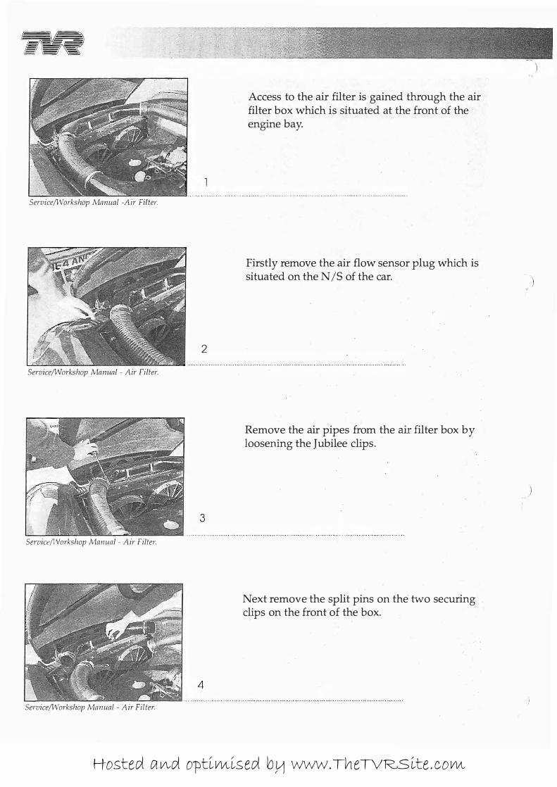
Access to the air filter is gained through the air filter box which is situated at the front of the engine bay.
Firstly remove the air flow sensor plug which is situated on the N /S of the car.
Remove the air pipes from the air filter box by loosening the Jubilee clips.
Next remove the split pins on the two securing clips on the front of the box.
)
Hosted and optimised by www.TheTVRSite.com
CERBERA SERVlCEI"WORKSHOP NIANUAL
5
Seruice/Workshop Manual - Air Filter.
6
Seruice/Workshop Manual - Air Filter.
7
Service/Workshop Manual - Air Filter.
8
Seruice/Workshop Manual - Air Filter.
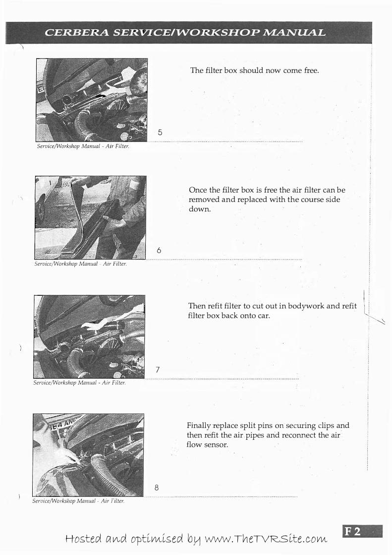
The filter box should now come free.
Once the filter box is free the air filter can be removed and replaced with the course side down.
Then refit filter to cut out in bodywork and refit l· filter box back onto car. • \..
Finallyreplace split pins on securing clips and then refit the air pipes and reconnect the air flow sensor.
Hosted and optimised by www.TheTVRSite.com
'iR --- --- - ------- --- - - -- - -
Service / Workshop Manual
Oil Pressure Switch
Hosted and optimised by www.TheTVRSite.com
2
Service/Workshop Manual - Oil Pressure Switch
Service/Workshop Manual - Oil Pressure Switch
4
Service/Workshop Manual - Oil Pressure Switch
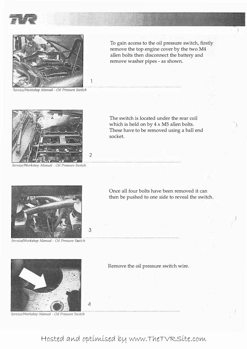
To gain access to the oil pressure switch, firstly remove the top engine cover by the two M4 alien bolts then disconnect the battery and remove washer pipes - as shown.
The switch is located under the rear coil which is held on by 4 x MS alien bolts. These have to be removed using a ball end socket.
Once all four bolts have been removed it can then be pushed to one side to reveal the switch ..
Remove the oil pressure switch wire.
)
Hosted and optimised by www.TheTVRSite.com
I. CERBERA SERVICElltVORKSHOP �NUAL
5
Service/Workshop Manual - Oil Pressure Switch
6
\
7
Service/Workshop Manual - Oil Pressure Switch
8
Service/Workshop Manual - Oil Pressure Switch
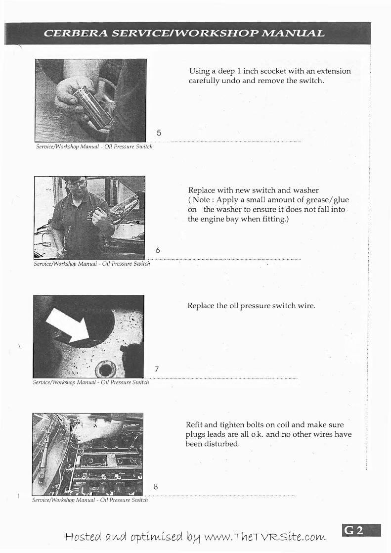
Using a deep 1 inch scocket with an extension carefully undo and remove the switch.
Replace with new switch and washer ( Note: Apply a small amount of grease/glue on the washer to ensure it does not fall into the engine bay when fitting.)
Replace the oil pressure switch wire.
Refit and tighten bolts on coil and make sure plugs leads are all o.k. and no other wires have been disturbed.
Hosted and optimised by www.TheTVRSite.com
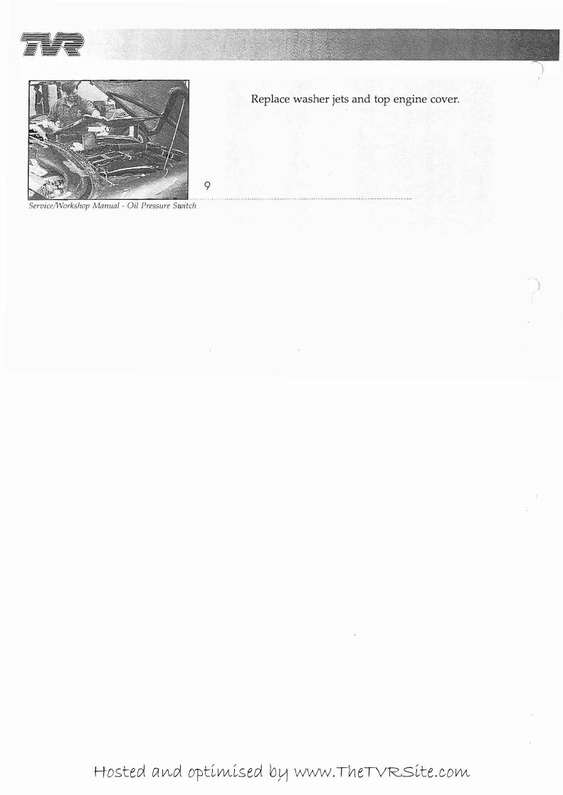
Replace washer jets and top engine cover.
9
ServiceIWorkshop Manual - Oil Pressure Switch
Hosted and optimised by www.TheTVRSite.com
CERBERA SERVICEI"WORKSHOP �NUAL
\
Notes
)
tit. Hosted and optimised by www.TheTVRSite.com