Embed Size (px)
Citation preview
Microprogrammed Control Control Unit
Initiate sequences of microoperations. The no. of micro operations in the systems are finite.
» The control function that specifies a microoperation is a binary variable. When it is in one state the corresponding microoperation is executed. The opposote state does not change the state of registers.
» Control signal (that specify microoperations) in a bus-organized system are groups of bits that select the paths in multiplexers, decoders, and arithmetic logic units
Two major types of Control Unit» Hardwired Control :
The control logic is implemented with gates, F/Fs, decoders, and other digital circuits + Fast operation, - Wiring change(if the design has to be modified)
» Microprogrammed Control : The control information is stored in a control memory, and the control memory is programmed
to initiate the required sequence of microoperations + Any required change can be done by updating the microprogram in control memory,
- Slow operation
Control Word: control unit initiates a series of microoperations. during any time certain microoperations are initiated while others are idle. The control variables at any given time can be represented by a string of 1’s and
0’s is called control word. Microprogrammed Control Unit
A control unit whose binary control variables are stored in memory (control memory).

Microinstruction : Each Word in Control Memory contains within it a microinstruction. The microinstruction specifies one or more microoperations
Microprogram A sequence of microinstruction
» Dynamic microprogramming : Control Memory = RAM RAM can be used for writing (to change a writable control memory) Microprogram is loaded initially from an auxiliary memory such as a magnetic disk
» Static microprogramming : Control Memory = ROM Control words in ROM are made permanent during the hardware production.
Microprogrammed control Organization :
1) Control Memory: A memory is part of a control unit.» Computer Memory
Main Memory : for storing user program (Machine instruction/data) Control Memory : for storing microprogram that can not be altered. The microprogram consist of Microinstruction
2) Control Address Register» Specify the address of the microinstruction
3) Sequencer (= Next Address Generator)» Determine the address sequence that is read from control memory» Next address of the next microinstruction can be specified several way depending on the
sequencer input
External input
Control Word
Next address generator(Sequencer)
Control address register
Control memory (ROM)
Control data register
Next address Information

4) Control Data Register (= Pipeline Register )» Hold the present microinstruction while the next add. Is computed & read from control memory» Allows the execution of the microoperations specified by the control word simultaneously with the
generation of the next microinstruction. This requires two phase clock, with one clock applied to add. Register and other to data register.
Address Sequencing: Microinstructions are stored in control memory in groups, with each group specifies a routine. The hardware that controls
the address sequencing of the control memory must be able of sequencing the microinstruction with a routine and be able to branch from one routine to another.
An initial address is loaded into the control address register when power is turned on.this address is the address of the first microinstruction that activates the fetch routine. After the end of fetch routine, the instruction is in the instruction register of the computer.
The control memory next must goes through the routine that determines the effective address of the operand. After computing the effective address the address of the operand is available in the memory address register.
The next step is to generate the microoperations that execute the instruction fetched from memory. The microoperation steps to be generated in processor registers depend upon the operation code part of instruction.
Each instruction has its own microprogram routine stored in a given location of the control memory.
The transformation from the instruction code bits to an address in the control memory where the routine is located is called as Mapping.
After the execution of the instruction control must return to the fetch routine. Address Sequencing Capabilities :
1) Incrementing of the control address register 2) Unconditional branch or conditional branch, depending on status bit conditions 3) Mapping process ( bits of the instruction address for control memory ) 4) A facility for subroutine return

I n s t r u c t i o n c o d e
M a p p i n gl o g i c
M u l t i p l e x e r s
C o n t r o l a d d r e s s r e g i s t e r( C A R )
C o n t r o l m e m o r y
I n c r e m e n t e r
S u b r o u t i n er e g i s e r( S B R )
B r a n c hl o g i c
Statusbits
Clock
selectMUX
Select a statusbit
Branch address
Microoperations

Selection of address for control memory : Multiplexer
CAR Increment
JMP/CALL
Mapping
Subroutine Return
CAR : Control Address Register»CAR receive the address from 4 different paths
1) Incrementer
2) Branch address from
control memory
3) Mapping Logic
4) SBR : Subroutine Register
SBR : Subroutine Register»Return Address can not be stored in ROM
»Return Address for a subroutine is stored in SBR
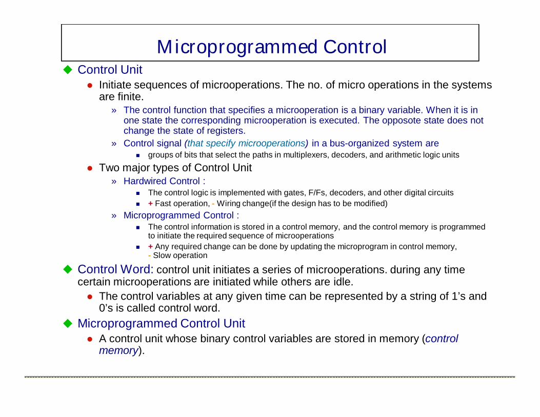
Conditional BranchingSpecial bits: Status conditions are special bits in the system that provide parameter information such as carry-out of an adder, sign bit of number, mode bits of an instruction, input /output status condition.
Information in these bits can be tested and actions initiated based on their condition; whether their value is 1 or 0.
The status bits together with the field in the microinstruction that specifies a branch address, control the conditional branch decisions generated in the branch logic.
Branch Logic: branch logic is used to test the specified condition and branch to the indicated address if the condition is met; otherwise the address register is incremented.this can be implemented with the help of multiplexer.
Ex. Let there are eight status bit conditions in the system. Three bits in the microinstruction are used to specify one of eight status bits. If the selected status bit is in the 1 state the output of the multiplexer is 1, otherwise 0. The 1 output in the multiplexer generates a control signal to transfer the branch address from the microinstruction into the control address register otherwise address register to be incremented.
The unconditional branch microinstruction can be implemented by loading the branch address from control memory into control address register.

MAPPING OF INSTRUCTIONS TO MICROROUTINESMapping from the OP-code of an instruction to the address of the Microinstruction which is the starting microinstruction of its execution microprogram
1 0 1 1 Address
Microinstructionaddress
OP-code
Mapping bits 0 x x x x 0 0
0 1 0 1 1 0 0
MachineInstruction
4 bit Opcode = specify up to 16 distinct instruction
Mapping Process : Converts the 4-bit Opcode to a 7-bit control memory address
»1) Place a “0” in the most significant bit of the address
»2) Transfer 4-bit Operation code bits
»3) Clear the two least significant bits of the CAR

ADD RoutineAND RoutineLDA RoutineSTA RoutineBUN Routine
ControlStorage
00000001001000110100
OP-codes of InstructionsADDANDLDASTA BUN
00000001001000110100
.
.
.
Direct MappingAddress
Mapping Function : Implemented by Mapping ROM or PLD. A PLD is similar to ROM except that it uses AND and OR gates with internal electronic fuses.the interconnection between AND, OR and outputs can be programmed as in ROM

Subroutine Subroutines are program that are used by other routines to accomplish a
particular task. A subroutine can be called from any point within the main body of the microprogram. Frequently many microprogram contain identical section of code. Microinstruction can be saved by employing subroutines that used common section of micro-code. Ex. The sequence of micro operations needed to generate the effective address of the operand for an instruction is common to all memory reference instructions. This sequence could be a subroutine that is called from within many other routines to execute the effective address computation.

Design of Control UnitThe bits of microinstruction are usually divided into fields, with each field
defining a distinct, separate function. The various fields available in the instruction format provide control bits to initiate the microoperation.
Decoding of Microinstruction Fields : F1, F2, and F3 of Microinstruction are decoded with a 3 x 8 decoder Output of decoder must be connected to the proper circuit to initiate the
corresponding microoperation (Tab. 7-1)

F1 = 101 (5) : DRTAR (The next clock pulse transition transfer the content of DR(0-10) to AR)
F1 = 110 (6) : PCTAR Output 5 and 6 of decoder F1 are
connected to the load input of AR (two input of OR gate)
Multiplexer select the data from DR when output 5 is active
Multiplexer select the data from AC when output 5 is inactive
Arithmetic Logic Shift Unit» Instead of using the gates to
generate the control signal marked by AND, ADD, and DR Control signal will be now come from the output of the decodersassociated with the AND, ADD, and DRTAC respectively.
3 × 8 d e c o d e r
7 6 5 4 3 2 1 0
F 1
3 × 8 d e c o d e r
7 6 5 4 3 2 1 0
F 2
3 × 8 d e c o d e r
7 6 5 4 3 2 1 0
F 3
A r i t h m e t i cl o g i c s h i f t
u n i t
A C
Multiplexers
A R
F r o mP C
F r o mD R ( 0 - 1 0 )
0 1
L o a d
S e l e c t
C l o c k
A D D
A N D
D R T A C
L o a d
D R T A RP C T A R
From DR

Microprogram Sequencer : Fig. 7-8 Microprogram Sequencer select the next
address for control memory MUX 1
» Select an address source and route to CAR
» JMP 와 CALL의 차이점 JMP : AD가 MUX 1의 2번을통해 CAR로전송 CALL : AD가 MUX 1의 2번을통해 CAR로
전송되고, 동시에 CAR + 1(Return Address) 이LOAD 신호에의해 SBR에 저장된다.
MUX 2 » Test a status bit and the result of the test is
applied to an input logic circuit» One of 4 Status bit is selected by Condition bit (CD)
Design of Input Logic Circuit» Select one of the source address(S0, S1) for
CAR» Enable the load input(L) in SBR
M U X 1
3 2 1 0
S 1
S 0
I n p u t l o g i c
I o
I 1
T
M U X 2
S e l e c t
C A R
In c r e m e n t e r
S B R
C o n t r o l m e m o r y
M i c r o o p s C D A DB R
C lo c k
T e s t
L o a d
E x t e r n a l( M A P )
L
1
ZS
I
CAR + 1 JMP/CALLMapping Subroutine Return

Input Logic Truth Table : Tab. 7-4» Input :
I0, I1 from Branch bit (BR) T from MUX 2 (T)
» Output : MUX 1 Select signal (S0, S1)
S1 = I1I0’ + I1I0 = I1(I0’ + I0) = I1S0 = I1’I0’T + I1’I0T + I1I0
= I1’T(I0’ + I0) + I1I0= I1’T + I1I0
SBR Load signal (L) L = I1’I0T
Load SBRI1 I0 T S1 S0 L
0 0 0 0 0 0 0 00 0 0 0 1 0 1 00 1 0 1 0 0 0 00 1 0 1 1 0 1 11 0 1 0 x 1 0 01 1 1 1 x 1 1 0
BR Field Input MUX 1
CAR + 1 JMP CAR + 1 CALLMAP RET
CALL