Embed Size (px)
Citation preview

Wheel Drive Circuit - General7.1.1Form T049
Section 7.1
Wheel Drive Circuit -General System
Simplified Travel Circuit Diagrams: Neutral Controls ................................ 7.1.2 Forward Travel.................................. 7.1.4 Reverse Travel ................................. 7.1.5
General................................................... 7.1.3
Wheel Drive Circuit: General ............................................. 7.1.6 Description: Mechanics ................................... 7.1.6 Charge Pump - Primary & Auxiliary ................................ 7.1.6 POR (Pressure Override) ............ 7.1.7 High Pressure Relief Valves ....... 7.1.7 Case Flushing Orifices ................ 7.1.7 Mechanics Of Operation ................... 7.1.12
Additional Diagrams: Charge Circuit ................................... 7.1.8 Wheel Drive Pump Breakdown......... 7.1.9 Wheel Drive Motor Installation (Dual Motor Configuration) ............ 7.1.10 Wheel Drive Motor Installation (Single Motor Configuration) ......... 7.1.11
Wheel Drive Circuit - General 7.1.2 Form T049
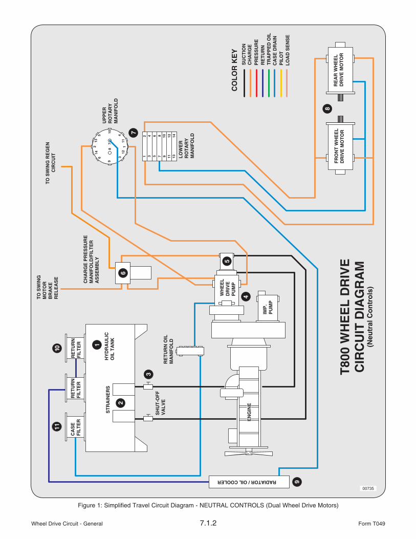
Figure 1: Simplified Travel Circuit Diagram - NEUTRAL CONTROLS (Dual Wheel Drive Motors)
00735

Wheel Drive Circuit - General7.1.3Form T049
General (See Figures 1, 2 & 3)
The wheel drive, or travel circuit, is a closed loop hydrostatic system made up of the following main components:
1) 110 gal. (416 litre) hydraulic oil tank forstorage and cooling of the hydraulic oil.See Section 2.2 in this manual for important information on the hydraulic tank and its components.
2) 100-mesh suction strainers.
3) Suction line shut-off valve.
4) Rexroth AA4VG125/3.2 series variable displacement, over-center, axial piston wheel drive pump.
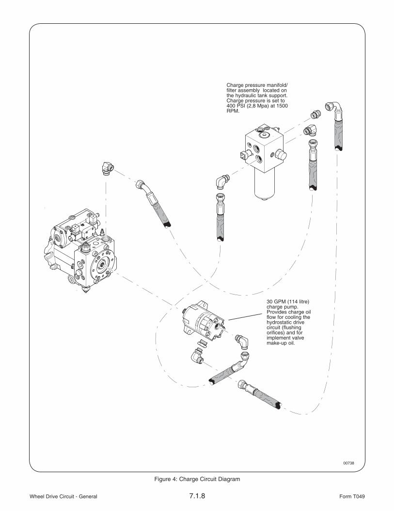
5) Charge pump piggy-back mounted to the wheel drive pump. The charge pump provides 30 GPM (114 litre) of flow at 400 PSI(2,76 Mpa). Charge pressure is controlled by the charge pressure manifold/filter assembly (Ref #6). The purpose of the charge pump is to provide make-up oil for the closed loop hydrostatic travel circuit. Flushing orifices in the pump and motors (and natural internal leakage) allow a small amount of oil to bleed from the hydrostatic loop. This leakage is replenished by the charge pump. A filter in the charge pressure manifold/filter assembly(Ref #6) cleans the charge oil before it enters the hydrostatic loop.
6) The charge pressure manifold/filter assembly contains the charge pressure relief and the charge oil filter. A sequence cartridge is used because the downstream pressure does not effect the valve pressure setting. Any increase . . . . . . . . . . . . . . . . . . of pressure downstream will not be additive to the charge pressure. This makes the charge pressure setting more constant. Charge pressure also provides stroke control for the wheel drive pump, swing brake release pressure, and pilot pressure at the pilot pressure manifold.
7) 14-port rotary manifold for 360° continuous rotation swing. In the wheel drive circuit it provides the hydrostatic link to the wheel drive motors, brake connections to the axles, and shift connections to the transfer case.
8) Rexroth AA6VM160 variable displacement wheel drive motor(s). Standard configuration is dual motors matched to an auto-shift gearbox. A single motor installation matched to a2-speed gearbox is optional.
The speed and drawbar pull of the machine is varied by changing the displacement of the wheel drive motor(s). In high range (fast speed less drawbar) the motor(s) are at minimum displacement. If the machine is in low range (low speed high drawbar) the motor(s) are at maximum displacement.
The dual motor configuration has an automatic shift mode that will seek the best displacement for the ground condition and machine load.
9) High capacity oil cooler with a 120°-140°F (49°-60°C) thermal bypass and 50 psi(3,45 kPa) back pressure bypass.
10/11) Return and case drain filters in the hydraulic tank. See Section 2.2 in this manual for important information on the hydraulic tank and its components.

Wheel Drive Circuit - General 7.1.4 Form T049
Figure 2: Simplified Travel Circuit Diagram - FORWARD TRAVEL (Dual Wheel Drive Motors)
00736

Wheel Drive Circuit - General7.1.5Form T049
Figure 3: Simplified Travel Circuit Diagram - REVERSE TRAVEL (Dual Wheel Drive Motors)
00737

Wheel Drive Circuit - General 7.1.6 Form T049
Wheel Drive Circuit
GeneralThe machine uses a dedicated pump and a single speed, auto-shifting gearbox powered by dual hydraulic motors for the wheel drive (travel) circuit. There is an optional drive for the Feller Buncher configurations which uses a 2-speed gearbox and a single motor.
The circuit type is a closed loop hydrostatic system. The directional changes in machine movement are controlled by swiveling the pump rotating group from a centered, neutral position to either forward or reverse. This is controlled by an electrical signal sent from a travel pedal actuated by the operator.
DescriptionA Rexroth 125cc AA4VG3.2 series pump is used on all configurations. This pump are referred to as a over-center pump. This means that the rotary group, which provides oil flow around the hydrostatic loop, can travel over-center on either side of the neutral swash plate position. This allows oil flow to be reversed in the hydrostatic loop. The direction of machine travel is controlled by the angle of the pump swash plate to either side of neutral.
The 125cc wheel drive pump is driven through a gearbox with a 1.38 speed increaser. Doing so allows the top engine RPM to be reduced from 2200 to 1900 (which is the peak torque level of the Cummins C8.3-C260 engine). This is being done to reduce the fuel required and reduce the noise level in the cab. Also, the fuel tank is now in the front frame and the implement valves have been moved behind the cab for easier service access.
One or two Rexroth AA6VE series variable displacement motors which are mated to either a single or 2-speed gearbox. The motors are set for different displacements to optimize the performance of the machine. These motors also utilize a 2-speed auto-shift mechanism as well as having case flushing orifices installed.
Mechanics
When the operator activates the travel pedal for the forward direction, an electrical signal is sent to the pump controller via the IQAN digital control system.
The electrical signal activates the solenoid on the pump controller, which in turn moves a small control spool that allows command oil to the pump servo. The pump servo is connected directly to the swash plate in the pump and when it is shifted, strokes up the pump in the desired direction and forces the pump to produce flow to the motors via the rotary manifold. When changing directions, the swash plate goes to the opposite side of neutral to change the direction of oil flow.
The oil returning from the motors is then routed through the rotary manifold to the opposite work port on the pump. This oil is then reused by the pump and sent back down to the motors.
Charge Pump
Because of the cooling requirements of the wheel drive circuit, it is necessary to push oil through flushing circuits to keep the pump and motors cool. The charge pump provide the make-up oil for cooling the closed loop hydrostatic pump/motors and to provide pump control pressure. The pump and motors have a natural manufacturing leakage which cannot be eliminated. This leakage must be made up or the closed loop system would run dry of oil. The charge system continually feeds oil into the low pressure side of the closed hydrostatic loop.
The maximum pressure setting of the charge circuit is regulated by a charge sequence valve located on the hydraulic tank support. Charge pressure is set at 400 PSI (2,76 Mpa) at 1500 RPM with ascrew-type adjustment cartridge. Charge pressure also is used to release the swing brake, supply the pilot pressure manifold, and as make-up oil for the implement valve to prevent cavitation.

Wheel Drive Circuit - General7.1.7Form T049
POR (Pressure Override)
The pressure override valve is unique in that it can limit the maximum allowed pump pressure without putting high pressure oil over a relief. See Figure 5.
When the machine encounters a condition where the drive pressure starts to exceed the maximum setting, the POR valve senses this. The POR valve then dumps the command oil that controls the pump servo to case. This allows the swash plate to move back towards the neutral position and reduce the pump flow to an amount that is enough to maintain the maximum allowed pressure.
The POR valve is adjustable and is set at 6000 PSI (41,4 Mpa) at 1500 RPM. See Section 7.2 in this manual for adjustment procedures.
High Pressure Relief Valves
The high pressure reliefs perform two important functions:
1) Prevent system or machine damage by venting oil from the hydrostatic loop should the machine stall against an immovable object. In this situation, a pressure spike is created in the circuit which could damage components. The high pressure reliefs sense this pressure spike and, if it exceeds the relief setting, vents oil from the hydrostatic loop into the charge system. This allows the pressure spike to dissipate without causing damage.
Venting oil through a high pressure relief also generates an excessive amount of heat, so it is important that they are adjusted properly. The high pressure reliefs are like a safety relief and are seldom active in a properly designed and adjusted circuit.
The high pressure reliefs are adjustable and are set at 6400 PSI (44,1 Mpa) at 1500 RPM. See Section 7.2 in this manual for adjustment procedures.
2) A high pressure relief, when located on the low pressure side of the hydrostatic loop, also acts as a check valve to allow charge oil to replenish the hydrostatic loop oil volume. This is required because of internal leakage in the pump and motors. If the leakage oil is not replaced, the hydrostatic loop would run low on
oil and component damage would occur.
Case Flushing Orifices
Both the pump and motors are equipped with case flushing orifices. The purpose of these orifices is to help keep the hydrostatic loop cool.
Hot oil in the hydrostatic loop is vented through the case flushing orifices into the case drains and then routed through the oil cooler. The vented loop oil is replaced by cool charge oil. This is very important, overheating would occur without the constant removal and replacement of a small amount of loop oil.
Pump Case Flushing Orifice
The pump case flushing orifice is located in the head of the pump and is part of the charge pressure spike relief. The charge spike relief protects the charge oil circuit from high pressure spikes.
The charge pressure spike relief is adjustable and is set at 490 PSI (3,8 Mpa) at 1500 RPM. See Section 7.2 in this manual for adjustment procedures.
Motor Case Flushing Orifice
The motor case flushing orifice is located in the control head of the motor.
Wheel Drive Circuit - General 7.1.8 Form T049
Figure 4: Charge Circuit Diagram
00738
Charge pressure manifold/filter assembly located on the hydraulic tank support. Charge pressure is set to 400 PSI (2,8 Mpa) at 1500 RPM.
30 GPM (114 litre) charge pump. Provides charge oil flow for cooling the hydrostatic drive circuit (flushing orifices) and for implement valve make-up oil.

Wheel Drive Circuit - General7.1.9Form T049
Figure 5: Wheel Drive Pump Breakdown
00739
High Pressure Relief. Clips high pressure spikes that the POR relief cannot react to.
Pressure Override Relief (POR). Primary high pressure relief for the travel circuit.
Pump Controller. Controls the pump’s swash plate angle for directional control.
High Pressure Relief

Wheel Drive Circuit - General 7.1.10 Form T049
Figure 6: Wheel Drive Motor Installation (Dual Motor Configuration)(Typical)
00599
RearRexroth AA6VM160Wheel Drive Motor, S/N# tag stamped 5652-004-031.
FrontRexroth AA6VM160Wheel Drive Motor, S/N# tag stamped 5652-004-031/002.
Front 031/002 Motor0-160cc
Rear 031 Motor85-160cc
Shift Pressure4400 PSI (30,3 Mpa)
Shift Pressure4000 PSI (27,6 Mpa)
0cc Start
85cc Start
160cc Full Stroke 160cc Full Stroke
Superior Single Speed Gearbox
Wheel Drive Motors & Gearbox (Dual Motor Configuration)
Dual wheel drive motor configurations use dual Rexroth axial piston drive motors bolted to a Superior single speed gear reduction box. This motor/gearbox combination can be located in the rear frame. The front and rear motors are different from each other in starting displacements and shift pressure settings. It is very important to replace the motor back with the same type if one should have to be replaced or removed.
IMPORTANT: The front motor S/N# tags are all stamped 5652-004-031/002 and the rear motor S/N# tags are all stamped 5652-004-031.

Wheel Drive Circuit - General7.1.11Form T049
Figure 7: Wheel Drive Motor Installation (Single Motor Configuration)(Typical)
00608
N.A.F. VG652-Speed Gearbox
Rexroth AA6VM160Wheel Drive Motor
Wheel Drive Motor & Gearbox (Single Motor Configuration)
The TB600 configurations are equipped with a single Rexroth axial piston drive motor bolted to a NAF 2-speed gear reduction box. This motor/gearbox combination is also located in the rear frame.

Wheel Drive Circuit - General 7.1.12 Form T049
Mechanics Of OperationOil flow is controlled by engine speed or RPM of the pump. The wheel drive motor(s), being driven by the pump, change displacement automatically depending on the drawbar requirements.
In a no load situation, the front motor (031/002) is set at 0cc displacement and the rear motor (031) is set at a minimum displacement of 85cc. When the machine starts to move and the pressure reaches 4000 PSI (27,6 Mpa) the front motor begins to shift. It will go from 0cc displacement all the way to the maximum displacement of 160cc. In this condition, when the pressure required to move the load reaches 4400 PSI (30,3 Mpa), the rear motor starts to shift off its minimum displacement of 85cc. It is likely, at this load requirement, that you will not see over 4500 PSI (27,6 Mpa) on the gauge for the following reason:
With the flow produced by the 125cc wheel drive pump at 1900 RPM feeding two 160cc motors, it would take more than 260 HP to reach the pump POR setting of 6000 PSI(41,4 Mpa).
Because of the HP requirement, it is very important to back off on the foot pedal to maintain engine RPM when a tough pull is encountered. By backing off on the pedal, the displacement of the pump is reduced allowing the engine to maintain its RPM while holding pressure to keep moving the load at the sacrifice of speed. The reason it is so important to maintain engine RPM is because when the engine is slowing under heavy load there is more heat being generated and without RPM the engine fan and water pump slow down, not giving the cooling efficiencies required.
When maximum drawbar is required for a tough pull, a rocker switch on the dash can be used to lock the wheel drive motor(s) in maximum displacement (low speed). See Figure 8.
Figure 8: Auxiliary Rocker Switch Bank #2(Wheel Drive Function Switches)
00396
Axle Lock “ON/OFF”
Hydraulic MotorShift “ON/OFF”
ParkingBrake

Wheel Drive Circuit - General7.1.13Form T049
THIS PAGE LEFT BLANK FOR NOTES

Wheel Drive Circuit - Tests & Adjustments7.2.1Form T050
Section 7.2
Wheel Drive Circuit -Tests & Adjustments
Safety Information . . . . . . . . . . . . . . . . . . . . . . . . . . . . . . . . . . . . . . . . 7.2.2
Tools Required . . . . . . . . . . . . . . . . . . . . . . . . . . . . . . . . . . . . . . . . . . 7.2.2
Wheel Drive Pump: Wheel Drive Charge Pressure . . . . . . . . . . . . . . . . . . . . . . . . . . . . 7.2.3 Wheel Drive Pump Directional Relief Pressure . . . . . . . . . . . . . . . 7.2.5 Wheel Drive Pump POR Pressure . . . . . . . . . . . . . . . . . . . . . . . . . 7.2.7 Wheel Drive Pump Null . . . . . . . . . . . . . . . . . . . . . . . . . . . . . . . . . 7.2.9 Wheel Drive Pump Case Drain Pressure . . . . . . . . . . . . . . . . . . . . 7.2.11
Wheel Drive Motor: Wheel Drive Motor Begin Of Stroke . . . . . . . . . . . . . . . . . . . . . . . . 7.2.12 Wheel Drive Motor Case Drain Pressure . . . . . . . . . . . . . . . . . . . . 7.2.15 Wheel Drive Motor Case Drain Flow . . . . . . . . . . . . . . . . . . . . . . . 7.2.17 MAX Displacement Lock Signal Pressure (Hydraulic motor shift signal pressure in single wheel drive motor configurations) . . . . . . . . . . . . . . . . . . . . . . . 7.2.18

Wheel Drive Circuit - Tests & Adjustments 7.2.2 Form T050
Safety information
You must read and understand the warnings and basic safety rules, found in Group-1 of theOperation & Maintenance manual, before performing any operation, test or adjustment procedures.
Tools Required• Tachometer• 0 - 60 psi (0 - 1000 kPa) pressure gauge• 0 - 600 psi (0 - 5 Mpa) pressure gauge• 0 - 6000 psi (0 - 50 Mpa) pressure gauge• 0 - 10,000 psi (0 - 80 Mpa) pressure gauge• 9/16”, 5/8”, 11/16”, 3/4”, 7/8”, 13/16”, 15/16”, 1-1/4”, & 1-3/8” wrenches• 5/32” & 1/4” allen wrenches• 10mm, 13mm, 17mm, 24mm wrenches• 3mm, 4mm, 5mm, 8mm allen wrenches• (2) PN# 15869, TIMBCO quick-couple adapter• PN# 16031, #4 ORS plug• PN# 16032, #8 ORS plug• PN# 15176, #4 ORS run tee• Gauge test hose• (2) Gauge test hose w/#4 JICF ends• #8 test hose w/#8 ORSF ends• 24” (61cm) jumper hose w/#4 JICM ends• (2) #6 ORBM - #4 JICM adapter• #12 ORBM - #4 JICM adapter• Calibrated container - 10 gallons (38 litres)• Stop watch
• The operator or another mechanic may berequired to operate a control while a pressurereading is being taken.
NOTE: Each machine is shipped fromthe factory with at least one 600 psi and one 10,000 psi gauge with quick-couple adapters. The gauges can be found in the machineUp-Time Kit.
At operating temperature, the engine, exhaust system components, cooling systemcomponents and hydraulic system components are HOT. Any contact can cause severe burns.
00017
Diesel exhaust fumes contain elements that are hazardous to your health. Always run engine in a well ventilated area. If in an enclosed space, vent exhaust to the outside.
00015

Wheel Drive Circuit - Tests & Adjustments7.2.3Form T050
Wheel Drive Charge Pressure
Specification:
DO NOT set charge pressure above 450 psig(3,10 Mpa). Overheating of the circuit and damage to the system can result.
425 psig (2,93 Mpa)
Test Standards:
• Hydraulics at operating temperature of140°F (60°C) or greater.
• Engine operating at high idle (approx. 1200 RPM).
Procedure:
1. Ensure the hydraulics are at correct operating temperature.
2. Start the engine and run at low idle.
3. Connect the 600 psi pressure gauge, with the quick-couple adapter attached, to the gauge port tap provided on the centralized pressure check manifold. See Figure 1.
NOTE: Only install a 600 psi pressure gauge after the engine is running. If the gauge is installed before the engine is started it canbe damaged.
6. Increase engine throttle to high idle (approx. 1200 RPM).
7. Read the pressure gauge, the wheel drive charge pressure should be set at 425 psig(2,93 Mpa).
If wheel drive charge pressure setting iscorrect, go to step #10. If adjustment is required, continue with step #8.
Figure 2: Wheel Drive Charge Pressure Manifold(Shown With Optional Charge Heater Installed)
00501
Figure 1: Wheel Drive Charge Pressure Gauge Port Tap
00582
Figure 3: Wheel Drive Charge Pressure Adjustment
00377

Wheel Drive Circuit - Tests & Adjustments 7.2.4 Form T050
8. Open the swing-out pump access guard and locate the wheel drive charge pressure manifold assembly. See Figure 2.
9. Locate the large charge pressure relief cartridge. See Figure 3. Use the 9/16” wrench and 5/32” allen wrench to loosen the jam nut.
Turning the adjustment setscrew CLOCKWISE increases the pressure setting. Turning thesetscrew COUNTER-CLOCKWISE decreases the pressure setting.
10. Read the pressure gauge, re-adjust pressure setting as required. After the correct pressure setting is made, tighten the jam nut to lock adjustment setting.
11. Shut down the engine. Remove the pressure gauge and secure the swing-out pump guard.

Wheel Drive Circuit - Tests & Adjustments7.2.5Form T050
Wheel Drive Pump Directional Relief Pressure
Specification:
6400 psig (44,14 Mpa)
Test Standards:
• Hydraulics at operating temperature of140°F (60°C) or greater.
• Engine operating at high idle (approx. 1200 RPM).
Procedure:
Operating the wheel drives over relief produces extreme heat that can damage hydraulicsystem components. Expedite all pressure readings and adjustments.
1. Ensure the hydraulics are at correct operating temperature.
2. Locate and disconnect the parking brakesolenoid coil harness (yellow wire) at the lower solenoid manifold. See Figure 4. This will prevent the parking brake from releasing.
NOTE: Lower solenoid manifold location varies by machine configuration.
3. Connect the 10,000 psi pressure gauge, with the quick-couple adapter attached, to the gauge port tap provided on the centralized pressure check manifold. See Figure 5.
4. Access the wheel drive pump behind theswing-out guard located below the hydraulic tank.
5. Before the directional reliefs can be set the wheel drive POR relief must be cancelled. Locate the POR relief on the wheel drive pump. See Figure 6.
Figure 4: Lower Solenoid Manifold(TB600 installation shown)
00565
Figure 5: Wheel Drive Pump Pressure Gauge Port Tap
00582
Figure 6: Wheel Drive PRO Relief
00675

Wheel Drive Circuit - Tests & Adjustments 7.2.6 Form T050
6. Use the 13mm wrench and 4mm allen wrench to loosen the jam nut on the POR reliefadjustment setscrew.
7. Very carefully, turn the POR adjustment screw in CLOCKWISE until it just touches bottom then back it off 1/4 turn. This cancels the POR relief and allows the gauge to read the directional relief settings.
NOTE: Do not turn the POR adjustment setscrew in too far or it will damage the relief valve when it bottoms out.
8. Instruct the operator or another mechanic to start the engine and run at high idle (approx. 1200 RPM).
9. On your signal, have the operator or another mechanic apply the travel brake and activate the FORWARD travel function while you take a pressure reading. Then activate the REVERSE travel function and take a reading. Wheel drive directional relief pressure should be set at 6,400 psig (44,14 Mpa) in both directions.
If wheel drive directional relief pressuresettings are correct, go to step #15. If an adjustment is required, continue with step #10.
10. Locate the directional relief for the direction of travel that requires adjustment. See Figure 7.
11. Use the 17mm wrench and 5mm allen wrench to loosen the jam nut on the directional relief adjustment setscrew.
13. On your signal, have the operator or another mechanic apply the travel brake and activate the required direction of travel while you set the directional relief to 6400 psig (44,14 Mpa).
Turning the adjustment setscrew CLOCKWISE increases the pressure setting. Turning thesetscrew COUNTER-CLOCKWISE decreases the pressure setting.
14. After the correct pressure setting is made,hold the adjustment setscrew stationary and tighten the jamnut to hold the pressure setting.
15. After testing or making adjustments to the wheel drive reliefs, re-adjust the wheel drive POR pressure setting to specification.
16. Shut down the engine and remove thepressure gauge.
17. Re-connect the parking brake solenoid coilharness. Close and secure the swing-out pump guard.
18. If possible, start the engine and operate the wheel drives to help cool the circuit down.
19. Shut down the engine.
Figure 7: Wheel Drive POR Relief
00675
REVERSETravel Relief
FORWARDTravel Relief

Wheel Drive Circuit - Tests & Adjustments7.2.7Form T050
Wheel Drive Pump POR Pressure
Specification:
6000 psig (41,38 Mpa)
Test Standards:
• Hydraulics at operating temperature of140°F (60°C) or greater.
• Engine at high idle (approx. 1200 RPM).
• Wheel drive pump charge pressure and charge spike relief set to specification.
Procedure:
Operating the wheel drives over relief produces extreme heat that can damage hydraulicsystem components. Expedite all pressure readings and adjustments.
1. Ensure the hydraulics are at correct operating temperature.
2. Locate and disconnect the parking brakesolenoid coil harness (yellow wire) at the lower solenoid manifold. See Figure 8. This will prevent the parking brake from releasing.
NOTE: Lower solenoid manifold location varies by machine configuration.
3. Connect the 10,000 psi pressure gauge, with the quick-couple adapter attached, to the gauge port tap provided on the centralized pressure check manifold. See Figure 9.
4. Instruct the operator or another mechanic to start the engine and run at high idle (approx. 1200 RPM).
5. On your signal, have the operator or another mechanic apply the travel brake and activate the FORWARD travel function while you takea pressure reading. Wheel drive pump POR pressure should be set at 6000 psig(41,38 Mpa).
If wheel drive pump POR pressure is correct, go to step #11. If an adjustment is required, continue with step #7.
Figure 8: Lower Solenoid Manifold(TB600 installation shown)
00565
Figure 9: Wheel Drive Pump Pressure Gauge Port Tap
00582

Wheel Drive Circuit - Tests & Adjustments 7.2.8 Form T050
6. Locate the POR relief on the wheel drive pump. See Figure 10. Use the 13mm wrench and 4mm allen wrench to loosen the jam nut on the POR relief adjustment setscrew.
7. On your signal, have the operator or another mechanic apply the travel brake and activate the FORWARD travel function while you set the POR relief to 6000 psig (41,38 Mpa).
Turning the adjustment setscrew CLOCKWISE increases the pressure setting. Turning thesetscrew COUNTER-CLOCKWISE decreases the pressure setting.
8. After the correct pressure setting is made,hold the adjustment setscrew stationary and tighten the jamnut to hold the pressure setting.
9. Shut down the engine and remove thepressure gauge.
10. Re-connect the parking brake solenoid coilharness. Close and secure the swing-out pump guard.
11. If possible, start the engine and operate the wheel drives to help cool the circuit down.
12. Shut down the engine.
Figure 10: Wheel Drive POR Relief
00675

Wheel Drive Circuit - Tests & Adjustments7.2.9Form T050
Wheel Drive Pump Null
Specification:
Obtain the lowest possible pressure between ports “X1” and “X2” with the jumper hose installed.
Test Standards:
• Hydraulics at operating temperature of140°F (60°C) or greater.
• Engine operating at idle
Procedure:
1. Ensure the hydraulics are at correct operating temperature.
2. Locate and disconnect the parking brakesolenoid coil harness (yellow wire) at the lower solenoid manifold. See Figure 11. This will prevent the parking brake from releasing.
NOTE: Lower solenoid manifold location varies by machine configuration.
3. Access the wheel drive pump behind theswing-out guard located below the hydraulic tank.
4. Using the 3/16” allen wrench, remove theplugs from ports “X1” and “X2”. See Figure 13. Install the #6 ORBM - #4 JICM adapters into the ports.
5. Connect the 24” (61cm) jumper hose between ports “X1” and “X2”.
6. Start the engine and run at idle. The engine will remain running throughout the procedure.
7. Connect the 10,000 psi pressure gauge, with the quick-couple adapter attached, to the gauge port tap on the wheel drive pump. See Figure 12.
Figure 11: Lower Solenoid Manifold(TB600 installation shown)
00565
Figure 12: Wheel Drive Pump Pressure Gauge Port Tap
00582

Wheel Drive Circuit - Tests & Adjustments 7.2.10 Form T050
8. The mechanical null adjustment is made with a large setscrew in the control piston cover. See Figure 13. Use the 24mm wrench and 8mm allen wrench, to loosen the jamnut and turn the adjustment setscrew in and out until the gauge reads the lowest possible pressure.
NOTE: The lowest pressure reading indicates when the control piston is in the centered null position.
9. Remove the 10,000 psi gauge and install the 600 psi gauge in its place. Repeat step #8 to make the final adjustment.
10. Remove the 600 psi gauge and install the 10,000 psi gauge in its place.
The hydraulic null adjustment is made with an eccentric pin and should not be turned more than 90° from center (as indicated by a notch on the adjustment screw), otherwise damage to the eccentric pin could result.
11. The hydraulic null adjustment is made with a small setscrew on top of the stroke control. See Figure 13. Use the 13 mm wrench and4 mm allen wrench, to loosen the jamnut and turn the adjustment setscrew in and out until the gauge reads the lowest possible pressure.
NOTE: The lowest pressure reading indicates when the control spool is in the centered null position.
12. Remove the 10,000 psi gauge and install the 600 psi gauge in its place. Repeat step #11 to make the final adjustment.
13. Shut-down engine and remove jumper hose, fittings, and gauge.
14. Re-connect the parking brake solenoid coilharness. Close and secure the swing-out pump guard.
15. Procedure complete.
Figure 13: Hydrostatic Pump Null Adjustments
00675
Port “X1”
Mechanical NullAdjustment Setscrew
Port “X2”
Hydraulic NullAdjustment Setscrew

Wheel Drive Circuit - Tests & Adjustments7.2.11Form T050
Wheel Drive Pump Case Drain Pressure
Specification:
Maximum 30 psig (0,21 Mpa) allowed.
Test Standards:
• Hydraulics at operating temperature of140°F (60°C) or greater with correct wheel drive and charge pressure settings.
• Engine operating at full throttle
Procedure:
1. Produce a gauge test hose that will allow you to connect a 60 psi gauge to the #4 JICM adapter that will be installed into the wheel drive pump case drain port.
2. Ensure the hydraulics are at correct operating temperature.
3. Locate and disconnect the parking brakesolenoid coil harness (yellow wire) at the lower solenoid manifold. See Figure 14. This will prevent the parking brake from releasing.
NOTE: Lower solenoid manifold location varies by machine configuration.
4. Access the wheel drive pump behind theswing-out guard below the hydraulic tank.
5. Locate and remove the wheel drive pump case drain plug in port “R”. Install the #12 ORBM - #4JICM adapter into the port.
6. Install the gauge test hose and pressure gauge to the case drain port adapter.
Be sure the pump case is full of oil before starting the machine otherwise catastrophic damage to the pump will occur.
7. Start engine and set the hydraulic motor shift control to the “OFF” position. See Figure 15.
8. Advance engine to full throttle.
9. On your signal, have the operator or another mechanic apply the travel brake and activate full FORWARD travel while you take a pressure reading. Then activate full REVERSE travel and take a reading.
The wheel drive pump case drain pressure should not exceed specification. If the specification is exceeded, look for conditions that would increase backpressure in the case drain circuit such as a plugged case drain filter element, failing component, etc.
10. Shutdown the engine and re-install the wheel drive pump case port plug.
11. Re-connect the parking brake solenoid coilharness.
12. Procedure complete.
Figure 15: Hydraulic Motor Shift Control
00396
Hydraulic MotorShift “ON/OFF”
Figure 14: Lower Solenoid Manifold(TB600 installation shown)
00565

Wheel Drive Circuit - Tests & Adjustments 7.2.12 Form T050
Wheel Drive MotorBegin Of Stroke
Specification:
In the standard configurations the front and rear wheel drive motors are different internally. There is a serial number plate attached to the underside of each motor for which identifies the motor displacement value. See Figure 16.
In dual motor applications require a 0cc motor in the front position and a 85cc motor in the rear. Single motor configurations use only the 85cc motor. Be sure to identify the motors before beginning adjustment procedures. Incorrect adjustment will overheat and possibly damage the machine.
Wheel drive pump POR relief pressure:
• 6000 psig (41,38 Mpa)
Begin of stroke pressure:
Dual Motors: • Front Motor - 4000 psig (27,6 Mpa) • Rear Motor - 4500 psig (31,0 Mpa)
Single Motor: 3500 psig (27,6 Mpa)
Shift pressure:
Dual Motors: • Front Motor - 2000 psig (13,8 Mpa) • Rear Motor - 2250 psig (15,5 Mpa)
Single Motor: 1750 psig (13,8 Mpa
Test Standards:
• Hydraulics at operating temperature of140°F (60°C) or greater with correct wheel drive and charge pressure settings.
• Engine at running at idle.
Operating the wheel drives over relief produces extreme heat that can damage hydraulicsystem components. Expedite all pressure readings and adjustments.
Procedure:
1. Ensure the hydraulics are at correct operating temperature.
2. Release turbo boost pressure at the turbo boost release valve. See Figure 17.
Figure 16: Motor S/N# Tag (Markings directlyabove the bar code identify this motor as a 75cc)
00586
Figure 17: Turbo Boost Release Valve
00517
Wheel Drive Circuit - Tests & Adjustments7.2.13Form T050
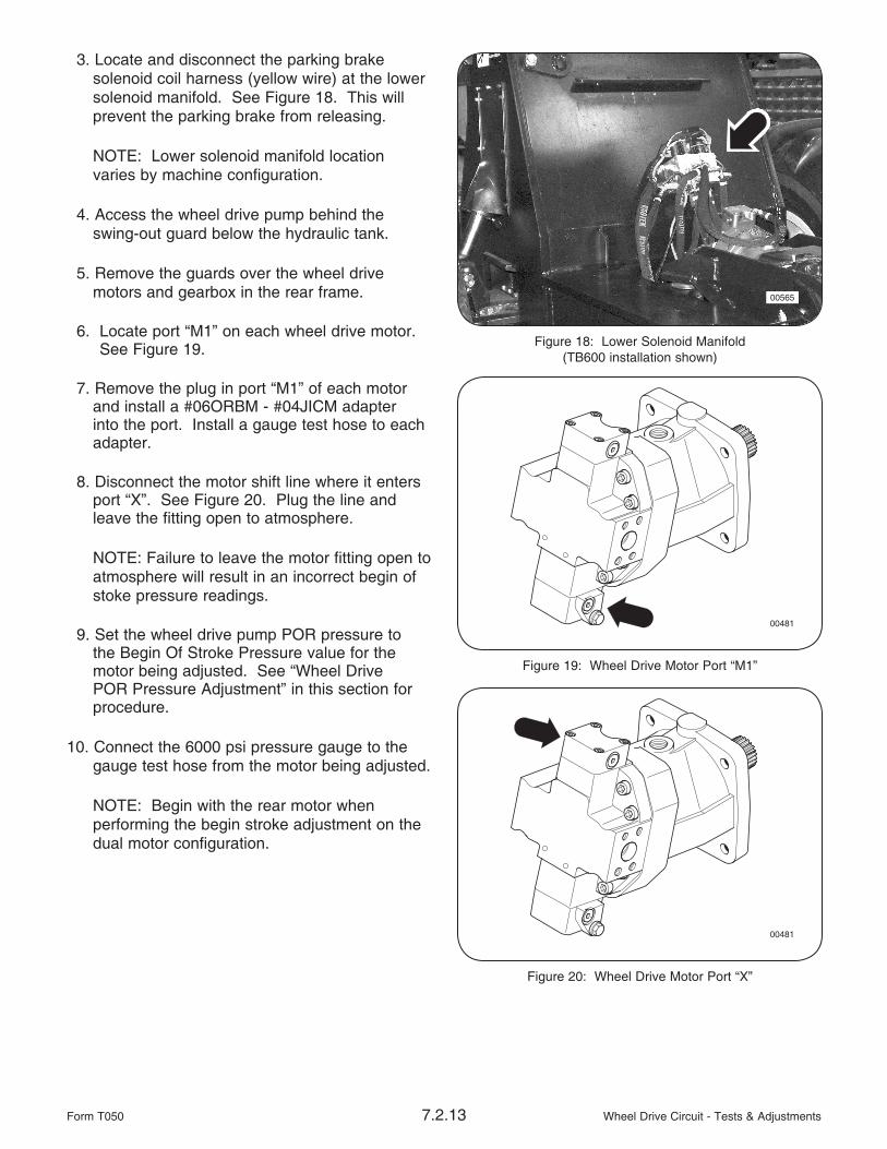
3. Locate and disconnect the parking brakesolenoid coil harness (yellow wire) at the lower solenoid manifold. See Figure 18. This will prevent the parking brake from releasing.
NOTE: Lower solenoid manifold location varies by machine configuration.
4. Access the wheel drive pump behind theswing-out guard below the hydraulic tank.
5. Remove the guards over the wheel drive motors and gearbox in the rear frame.
6. Locate port “M1” on each wheel drive motor. See Figure 19.
7. Remove the plug in port “M1” of each motor and install a #06ORBM - #04JICM adapter into the port. Install a gauge test hose to each adapter.
8. Disconnect the motor shift line where it enters port “X”. See Figure 20. Plug the line and leave the fitting open to atmosphere.
NOTE: Failure to leave the motor fitting open to atmosphere will result in an incorrect begin of stoke pressure readings.
9. Set the wheel drive pump POR pressure to the Begin Of Stroke Pressure value for the motor being adjusted. See “Wheel Drive POR Pressure Adjustment” in this section for procedure.
10. Connect the 6000 psi pressure gauge to the gauge test hose from the motor being adjusted.
NOTE: Begin with the rear motor when performing the begin stroke adjustment on the dual motor configuration.
Figure 19: Wheel Drive Motor Port “M1”
00481
Figure 18: Lower Solenoid Manifold(TB600 installation shown)
00565
Figure 20: Wheel Drive Motor Port “X”
00481

Wheel Drive Circuit - Tests & Adjustments 7.2.14 Form T050
13. Locate the begin stroke adjustment setscrew on the motor. See Figure 31. Use the 10mm wrench and 3mm allen wrench to loosen the jamnut and back the setscrew out COUNTER-CLOCKWISE a few turns. This will allow easier setting of the motor.
NOTE: The begin of stroke adjustment is made using the motor shift pressure at port “M1”. The motor shift pressure should be 1/2 the desired begin of stroke pressure.
14. On your signal, have the operator or another mechanic apply the travel brake and activate full FORWARD travel function while you turn the begin of stoke setscrew in CLOCKWISE until the shift pressure reaches specification.
15. Instruct the operator or another mechanic to deactivate the FORWARD travel function as soon as the adjustment is made to avoid excessive heat build-up in the wheel drive circuit.
16. After the correct pressure setting is made,hold the adjustment setscrew stationary and tighten the jamnut to hold the pressure setting.
17. If required, repeat step #12 thru #16 for the front wheel drive motor.
18. After begin of stroke pressure have been adjusted, reset the wheel drive pump POR relief pressure to specification.
19. Shut down the engine.
20. Release turbo boost pressure at the turbo boost release valve.
21. Remove the #06ORBM - #04JICM adapters and gauge test hoses from the wheel drive motors. Re-install the plugs to port “M1”.
25. Re-install the guards over the wheel drive motors and transfer case.
26. Re-connect the parking brake solenoid coilharness. Close and secure the swing-out pump guard.
27. Procedure complete.
Figure 21: Wheel Drive Motor Begin Of Stoke Adjustment
00482

Wheel Drive Circuit - Tests & Adjustments7.2.15Form T050
Wheel Drive Motor Case Drain Pressure
Specification:
Maximum 45 psig (0,31 Mpa) allowed.
Test Standards:
• Hydraulics at operating temperature of140°F (60°C) or greater with correct wheel drive and charge pressure settings.
• Engine operating at full throttle.
Procedure:
1. Produce a gauge test hose that will allow you to connect a 60 psi gauge to the #4 JICM adapter that will be installed into the wheel drive motor case drain port.
2. Ensure the hydraulics are at correct operating temperature.
3. Locate and disconnect the parking brakesolenoid coil harness (yellow wire) at the lower solenoid manifold. See Figure 22. This will prevent the parking brake from releasing.
NOTE: Lower solenoid manifold location varies by machine configuration.
4. Access the wheel drive pump behind theswing-out guard below the hydraulic tank.
5. Remove the guards over the wheel drive motors and gearbox in rear frame.
6. Locate and remove a wheel drive motor case drain plug in a port 180° from the motor’s case drain line. Install the #12 ORBM - #4JICM adapter into the port.
7. Install the gauge test hose and pressure gauge to the case drain port adapter.
Be sure the pump case is full of oil before starting the machine otherwise catastrophic damage to the pump will occur.
8. Start engine and run at idle.
9. Set the hydraulic motor shift control to the “OFF” position. See Figure 23.
10. Advance engine to full throttle.
11. On your signal, have the operator or another mechanic apply the travel brake and activate full FORWARD travel while you take a pressure reading. Then activate full REVERSE travel and take a reading.
12. Shutdown the engine and re-connect the parking brake solenoid coil signal wire.
13. Start the engine and move the machine several feet forward.
Figure 22: Lower Solenoid Manifold(TB600 installation shown)
00565
Figure 23: Hydraulic Motor Shift Control
00396
Hydraulic MotorShift “ON/OFF”

Wheel Drive Circuit - Tests & Adjustments 7.2.16 Form T050
14. Shutdown the engine and disconnect the parking brake solenoid coil signal wire.
15. Repeat step #8 thru #11 with the machine in the new position.
The wheel drive motor case drain pressure should not exceed specification. If the specification is exceeded, look for conditions that would increase backpressure in the case drain circuit such as a plugged case drain filter element, failing component, etc.
16. Shutdown the engine and re-install the wheel drive motor case port plug.
17. Re-connect the parking brake solenoid coilsignal wire.
18. Re-connect the parking brake solenoid coilharness. Close and secure the swing-out pump guard.
19. Procedure complete.
Wheel Drive Circuit - Tests & Adjustments7.2.17Form T050
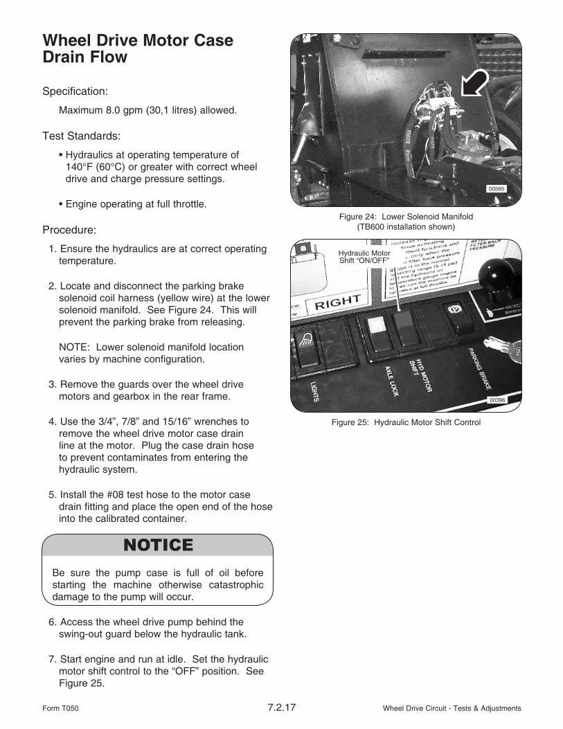
Wheel Drive Motor Case Drain Flow
Specification:
Maximum 8.0 gpm (30,1 litres) allowed.
Test Standards:
• Hydraulics at operating temperature of140°F (60°C) or greater with correct wheel drive and charge pressure settings.
• Engine operating at full throttle.
Procedure:
1. Ensure the hydraulics are at correct operating temperature.
2. Locate and disconnect the parking brakesolenoid coil harness (yellow wire) at the lower solenoid manifold. See Figure 24. This will prevent the parking brake from releasing.
NOTE: Lower solenoid manifold location varies by machine configuration.
3. Remove the guards over the wheel drive motors and gearbox in the rear frame.
4. Use the 3/4”, 7/8” and 15/16” wrenches to remove the wheel drive motor case drain line at the motor. Plug the case drain hose to prevent contaminates from entering the hydraulic system.
5. Install the #08 test hose to the motor case drain fitting and place the open end of the hose into the calibrated container.
Be sure the pump case is full of oil before starting the machine otherwise catastrophic damage to the pump will occur.
6. Access the wheel drive pump behind theswing-out guard below the hydraulic tank.
7. Start engine and run at idle. Set the hydraulic motor shift control to the “OFF” position. See Figure 25.
Figure 25: Hydraulic Motor Shift Control
00396
Hydraulic MotorShift “ON/OFF”
Figure 24: Lower Solenoid Manifold(TB600 installation shown)
00565

Wheel Drive Circuit - Tests & Adjustments 7.2.18 Form T050
9. Advance engine to full throttle..
10. On your signal, have the operator or another mechanic apply the travel brake and activate full FORWARD travel.
11. After one minute, deactivate the travel function and shutdown the engine.
12. Remove the wheel drive motor case drain hose from the container.
13. Measure the oil in the container. If the amount exceeds specification, the wheel drive motor is worn or failing and may have to be replaced.
14. Repeat steps #11 thru #14 for REVERSE travel.
15. Shutdown the engine and re-connect the wheel drive motor case drain hose to the motor.
16. Re-connect the parking brake solenoid coilharness. Close and secure the swing-out pump guard.
17. Procedure complete.
MAX Displacement Lock Signal Pressure
NOTE: Use this test for the hydraulic motor shift signal pressure in optional single wheel drive motor configurations.
Specification:
• OFF - 0 psig (0 Mpa)
• ON - 400 psig (Non-adjustable)
Test Standards:
• Hydraulics at operating temperature of140°F (60°C) or greater.
• Engine operating at high idle (approx. 1200 RPM).
Procedure:
1. Ensure the hydraulics are at correct operating temperature.
2. Remove the guards over the wheel drive motors and transfer case.
3. Locate the #04 MAX displacement lock signal hose where it connects the top control covers of both motors.
4. disconnect the hose at the front motor and install the #4 ORS run tee between the motor and hose.
5. Install the gauge test hose and 600 psi gauge to the tee.
6. Start the engine and adjust the throttle tohigh idle (approx. 1200 RPM).

Wheel Drive Circuit - Tests & Adjustments7.2.19Form T050
7. Instruct the operator or another mechanic to select hydraulic motor shift “ON” (switch lighted) while you take a pressure reading. See Figure 26. Record the pressure reading.
8. Instruct the operator or another mechanic to select hydraulic motor shift “OFF” while you take a pressure reading. Record the pressure reading.
9. If the MAX displacement lock signal pressure doesn’t meet specifications, check for leakage past the seals of the motor shift solenoid valve (green wire) located in the lower solenoid manifold. See Figure 27.
NOTE: Lower solenoid manifold location varies by machine configuration.
Figure 26: Hydraulic Motor Shift Control
00396
Hydraulic MotorShift “ON/OFF”
Figure 27: Lower Solenoid Manifold(TB600 installation shown)
00565

Wheel Drive Circuit - Tests & Adjustments 7.2.20 Form T050
THIS PAGE LEFT BLANK FOR NOTES