Embed Size (px)
Citation preview

NO SCALE619-1
STANDARD APPROVED FOR USE 6/2005
DRAFT: 10/2016
REVISED:
CATTLE GUARD
STATE PROJECTNUMBER
SHEET
U.S. DEPARTMENT OF TRANSPORTATION
FEDERAL HIGHWAY ADMINISTRATION
]
US
C [
C:\
MyFiles\p
w_production\d
ms67488\Std
619-1.d
gn
4:21 P
M
5 O
cto
ber 2
016
FEDERAL LANDS HIGHWAY
U.S. CUSTOMARY STANDARD
STANDARD
48"
bid schedule
TYPE I TYPE II
SECTION VIEW
DETAIL A DETAIL B
PLAN
DETAIL C DETAIL D
DETAIL E DETAIL F
ALUMINUM TUBING WING GUARD
END SUPPORT DETAIL
STANDARD GRID UNIT TYPES
ACCEPTABLE ALTERNATE RAIL
WOOD WING GUARD ANGLE IRON WING GUARD
See Detail A
A3 tie Bars
14.
13.
12.
11.
10.
9.
8.
7.
6.
5.
4.
3.
2.
1.guard as shown in the
Nominal width of cattle
(See Details)
Standard grid unit types
Lateral support
Rails
drain pipe treated timber (S4S)
flat washer
w/nut and
hex bolt
Timber sill
bars to angle iron
guard angles
See Detail C
flat washer
w/nut and
hex bolt
flat washer
w/nut and
hex bolt
See Detail F
aluminum tubing
to provide for crown
cut vertical leg only
leg only. Field saw
centers in vertical
Base plate
See Detail E
(typ.) welded to
Pay Limits, cattle guard
(See Detail)
End support
10d galvanized nails
See Detail DSee Detail B
(equal spacing)
A2 tie Bars
A4 BarsA1 Bars
A1 Bars
wing guard
only with wood
Timber sill-use
A5 Bars
after fabrication
weld. Galvanize each assembly
angle with full penetration butt
treated timber post (S4S)treated timber post (S4S)
post (S4S) or approved alternate
(2 each/base plate)
w/flat washer and nut
sill (S4S)
Treated timber
Toenail with 16d galvanized nails
Bond pad to concrete (typ.)
elastomeric bearing
cut weld
Saddle
I & II rail
ASCE 40 rail
Slope to drain
guard angles
ASCE 40 CRANE RAIL
Face of end support
w/nut and flat washer
steel rod threaded
(4 required per cattle guard)
GUARD ANGLE DETAIL
to AASHTO ASTM A36 and is painted.
alternate sections. All other structural steel conforms
contain a minimum of 0.2 percent copper, galvanize the
Copper Steel or ASTM A 618, Grade 2. If the steel does not
for alternate sections conforming to ASTM A 500, Grade B,
requirements for ASCE 40 crane rail. Provide structural steel
STRUCTURAL STEEL: Provide rails conforming to the
shown. Give all concrete surfaces a Class 1 finish.
Place one object marker at each corner of the cattle guard
roadway grade and template.
Construct the cattle guard to conform with the finished
Galvanize all hardware according to AASHTO M 111.
with chromated copper arsenate according to AASHTO M 133.
Provide timber conforming to AASHTO M 168. Treat timber
Use aluminum alloy 6061-T6 or 6063-T6 for aluminum tubing.
at each intersection. Weld according to Section 555.
Install channels and wood blocking on cattle guards wider
damage to the paint system during installation.
Federal Standard 595B, Gray, 36231. Repair any
to Section 555 and color the top coat according to
Requirements, shop apply paint system 2 according
Unless otherwise shown in the Special Contract
pipe with cattle guard unless otherwise shown.
Install drain pipe as shown where required. Include drain
the lateral support concrete.
timber (S4S)
LOADING: AASHTO HS20.
6" x 6" x 96"
" dia.21Weld
30" treated
2" x 6" x 84"
6" x 6" x 96"
2" x 8" x 96"
" dia. x 7"21
" dia. x 6"83
" dia. x 7"83
"41
6" x 6" x 96" treated timber
12" for
"812" OD x
"83L 3" x 3" x
(#4 Reinforcing Bars)
" dia. holes at 48"±165
8"
6"and 8" leg anchors. Weld to
centers alternating 6" leg
" x 6" hex bolt83
"41
"83L 3" x 3" x
"83L 3" x 3" x
6" min.
48"
48"
"837" x 8" x
" x 8" stud21
"81L 1" x 1" x
" anchors at 12"21Space
"83L 3" x 3" x
9"12"
"2
13
" for type2111
9"
39"
12"
31"
36"
4"
"21
4
12"R
12"R
12"
42"
3"
1"
2"
4"
3"
pad under W8 x 18.42"
18"
24"
96"
60"
9"
9"
9"
9"
42"
6"
20"20"20"
6"6"
21"21"21"21"
6"
"83
"4171 "4
195
"83
8'-0" grid
Grid Type B
6'-0" grid
Grid Type A
(ty
p.)"
81
8
(ty
p.)
"8
3
at 24" increments
12" thru 42"
42"42"
3"
3"
3"
2"
" max.414
4" min.
2"4" max.
3" min.
"163
3"
"43
"4110" x 5" x
"21
4
" x 16" 433" radius hook -
" unless otherwise 43CONCRETE: Chamfer exposed edges
" fillet shop welds. Weld rail 41All welds are continuous
or alternate sections on both sides to the W 8 x 18 beams
bar unless otherwise shown. All bars are #4.
Provide 2" minimum concrete cover to the face of any
See Standard 619-3 for optional precast foundation details.
on Standard 619-2.
than 16 feet to maintain grate spacing as shown
with the reflector located 42" above the elevation of
as shown. Mount object markers on 4" x 4" x 6'-0" posts
"83
"83
18"
9"9"
72" treated
2" x 6" x
NOTE:
guard angle
corner. See Note 10
Object marker each
timber braces (S4S)
A5 Bars
" x 74"41L 2" x 2" x
W 8 x 18 beams
(10" centers)
" x 87"41L 2" x 2" x
12"
12"
12"
12"
12"
"832
"812
"832
"812
12"
18"
24"
6"

NO SCALESTANDARD APPROVED FOR USE 3/1996
DRAFT: 10/2016
REVISED: 6/1997 6/2005 619-1M
CATTLE GUARD
STATE PROJECTNUMBER
SHEET
U.S. DEPARTMENT OF TRANSPORTATION
FEDERAL HIGHWAY ADMINISTRATION
]M
etric
[
c:\m
yfiles\p
w_production\d
ms67488\Std
619-1.d
gn
4:19 P
M
5 O
cto
ber 2
016
FEDERAL LANDS HIGHWAY
STANDARD
METRIC STANDARD
L 51 x 51 x 6.4 x 1850
W 200 x 27 beams
(250 centers)
bid schedule
TYPE I TYPE II
SECTION VIEW
DETAIL A DETAIL B
PLAN
DETAIL C DETAIL D
DETAIL E DETAIL F
ALUMINUM TUBING WING GUARD
END SUPPORT DETAIL
STANDARD GRID UNIT TYPES
ACCEPTABLE ALTERNATE RAIL
WOOD WING GUARD ANGLE IRON WING GUARD
See Detail A
A3 tie Bars
14.
13.
12.
11.
10.
9.
8.
7.
6.
5.
4.
3.
2.
1.guard as shown in the
Nominal width of cattle
(See Details)
Standard grid unit types
Lateral support
Rails
drain pipe treated timber (S4S)
flat washer
w/nut and
hex bolt
Timber sill
bars to angle iron
guard angles
See Detail C
flat washer
w/nut and
hex bolt
flat washer
w/nut and
hex bolt
See Detail F
aluminum tubing
to provide for crown
cut vertical leg only
leg only. Field saw
centers in vertical
Base plate
See Detail E
(typ.) welded to
Pay Limits, cattle guard
(See Detail)
End support
10d galvanized nails
See Detail DSee Detail B
(equal spacing)
A2 tie Bars
A4 BarsA1 Bars
A1 Bars
wing guard
only with wood
Timber sill-use
A5 Bars
after fabrication
weld. Galvanize each assembly
angle with full penetration butt
treated timber post (S4S)treated timber post (S4S)
post (S4S) or approved alternate
(2 each/base plate)
w/flat washer and nut
sill (S4S)
Treated timber
Toenail with 16d galvanized nails
Bond pad to concrete (typ.)
elastomeric bearing
cut weld
Saddle
I & II rail
ASCE 40 rail
Slope to drain
guard angles
ASCE 40 CRANE RAIL
Face of end support
w/nut and flat washer
steel rod threaded
(4 required per cattle guard)
GUARD ANGLE DETAIL
to AASHTO ASTM A36 and is painted.
alternate sections. All other structural steel conforms
contain a minimum of 0.2 percent copper, galvanize the
Copper Steel or ASTM A 618, Grade 2. If the steel does not
for alternate sections conforming to ASTM A 500, Grade B,
requirements for ASCE 40 crane rail. Provide structural steel
STRUCTURAL STEEL: Provide rails conforming to the
shown. Give all concrete surfaces a Class 1 finish.
Place one object marker at each corner of the cattle guard
roadway grade and template.
Construct the cattle guard to conform with the finished
Galvanize all hardware according to AASHTO M 111.
with chromated copper arsenate according to AASHTO M 133.
Provide timber conforming to AASHTO M 168. Treat timber
Use aluminum alloy 6061-T6 or 6063-T6 for aluminum tubing.
at each intersection. Weld according to Section 555.
Install channels and wood blocking on cattle guards wider
damage to the paint system during installation.
Federal Standard 595B, Gray, 36231. Repair any
to Section 555 and color the top coat according to
Requirements, shop apply paint system 2 according
Unless otherwise shown in the Special Contract
pipe with cattle guard unless otherwise shown.
Install drain pipe as shown where required. Include drain
the lateral support concrete.
timber (S4S)
15.
150 x 150 x 2400
750 treated
50 x 150 x 2100
150 x 150 x 2400
M10 x 175
150 x 150 x 2400 treated timber
M10 x 150
650 x 200 x 2400
50 OD x 3.17
290 for type
305 for
M10 x 150 hex bolt
6
and 200 leg anchors. Weld to
centers alternating 150 leg
Space M12 anchors at 3008 dia. holes at 1200±
200
150
(#13 Reinforcing Bars)
L 76 x 76 x 9.5
M12 x 200 stud
L 25 x 25 x 3.2
L 76 x 76 x 9.5
L 76 x 76 x 9.5
150 min.
M12 x 175
Weld 12 dia.
300
300
300
300
300
225
975
L 51 x 51 x 6.4 x 2210
L 76 x 76 x 9.5
250 x 125 x 6.4
76
764.76
88.9 88.9
88.9
108 max.
100 min.
47.6100 max.
75 min.
76
76
20
1050
75 radius hook - M20 x 400
CONCRETE: Chamfer exposed edges 20 mm unless otherwise
LOADING: AASHTO MS18.
or alternate sections on both sides to the W 200 x 27 beams
All welds are continuous 6 mm fillet shop welds. Weld rail
bar unless otherwise shown. All bars are #13.
Provide 50 mm minimum concrete cover to the face of any
with the reflector located 1050 mm above the elevation of
as shown. Mount object markers on 100 x 100 x 1950 posts
Dimensions without units are millimeters.
See Standard M619-3 for optional precast foundation details.
on Standard M619-2.
than 4.8 m to maintain grate spacing as shown
600
450
1200
300
450
600
300
300
1050
2400
1500
225
225
225
225
at 0.6 m increments
3.6 m thru 12.6 m
(ty
p.)
10
1200
1200
2400 grid
Grid Type B
1800 grid
Grid Type A
500500500 525525525525
150150150
1780
150
10
2380
10
1010
(ty
p.)
207
225225
450
pad under W 200 x 27.
175 x 200 x 9.5
1050
150
110
100
110
300R
300R
300
775
900
75
75
50
100
25
225
50
1800 treated
50 x 150 x
60
55
60
55
NOTE:
guard angle
corner. See Note 10
Object marker each
timber braces (S4S)
A5 Bars

NO SCALE
CATTLE GUARD
CATTLE GUARD WING
2
8
10
32
20
8
1
1
8
10
36
20
8
2
8
10
40
20
8
3
8
10
46
20
8
1
2
8
10
50
20
8
2
1
8
10
54
20
8
3
8
10
60
20
8
1
3
8
10
64
20
8
2
2
8
10
70
20
8
5
8
10
74
20
8
4
8
100
80
20
8
2
3
8
10
84
20
8
6
8
10
90
20
8
4
1
8
10
94
20
8
5
8
10
98
20
8
7
8
10
102
20
8
REINFORCING STEEL, CONCRETE, STRUCTURAL STEEL, AND GRID UNIT TABLE OF QUANTITIES
DESCRIPTION
LENGTHREMARKS
WOOD WING
GRID UNIT TYPE B
GRID UNIT TYPE A
No. 4
No. 5
No. 6
Post
None
None
None
OF MATERIALS
GRID UNIT LIST
assembly
anchor
Bottom
assembly
anchor
Top
NOMINAL CATTLE GUARD WIDTH
DESCRIPTION
PART
support
Middle
supports
diagonal
Outside
ANGLE IRON WING ALUMINUM TUBING WING
treated S4S
treated S4S
treated S4S
treated S4S
treated S4S
galvanized steel bar
galvanized steel bar
galvanized steel bar
galvanized steel bar
galvanized steel bar
treated S4S
w/nut and flat washer
galvanized hex bolt
galvanized steel bar
approved alternate
treated S4S or
hook in other end
one end w/nut and
steel rod threaded on
(with minimum spacing),
tubular cross bar sections,
minimum spacing), or II
ASCE 40 crane rail (with
(with minimum spacing),
tubular cross bar sections,
minimum spacing), or II
ASCE 40 crane rail (with
QTY
(TWO REQUIRED PER INSTALLATION)
LIST OF MATERIALS PER WING
brace No. 1
Horizontal
QTY LENGTH QTY LENGTH QTY LENGTH QTY LENGTH QTY LENGTH QTY LENGTH QTY LENGTH QTY LENGTH QTY LENGTH QTY LENGTH QTY LENGTH QTY LENGTH QTY LENGTH QTY LENGTH QTY LENGTH
No. 2
No. 3 None
None
None
None
See Grid Unit List of Materials
See Grid Unit List of Materials
See Bar Bending Detail
See Bar Bending Detail
* Structural steel weights do not include hardware or guard angle.
w/16d galvanized nails
supports to wooden sill
Toenail diagonal
embedded in concrete.
w/nuts & washers
to concrete w/ 3 each
treated S4S sill attached
the bolts with washer & nuts
Attach the flat iron plates to
embedded in concrete.
galvanized hex bolts
flat irons welded to
*Str
uctural
or approved alternate
washer and nut
to bolt w/flat
Attach steel L iron
embeded in concrete.
galvanized hex bolts
as required
16d galvanized nails
to the post with
Toenail diagonal supports
619-2
STANDARD APPROVED FOR USE 6/2005
DRAFT: 5/2008
REVISED:
CATTLE GUARD
Reinforcing steel, lb
Rail, Type II
Rail, Type I
Rail, ASCE 40
W 8 x 18 beams
Total concrete, yd3
Concrete end supports, yd3
Concrete lateral supports, yd3
Grid unit B (8 ft)
Grid unit A (6 ft)
#4 Reinforcing bars, A5
#4 Reinforcing bars, A4
#4 Reinforcing bars, A3
#4 Reinforcing bars, A2
#4 Reinforcing bars, A1
478
1060
806
2052
936
5.59
4.03
1.56
140"
156"
108"
86"
92"
12' 14' 16' 18' 20'
212"
228"
108"
86"
92"
188"
204"
108"
86"
92"
164"
180"
108"
86"
92"
526
1238
942
2398
1053
6.26
4.70
1.56
574
1416
1078
2744
1170
6.93
5.37
1.56
634
1590
1209
3078
1404
7.60
6.04
1.56
683
1768
1345
3424
1521
8.27
6.71
1.56
236"
252"
108"
86"
92"
22' 24' 26'
260"
276"
108"
86"
92"
731
1946
1481
3770
1638
8.94
7.38
1.56
284"
300"
108"
86"
92"
791
2124
1617
4116
1755
9.61
8.05
1.56
839
2298
1748
4450
1989
10.29
8.73
1.56
308"
324"
108"
86"
92"
332"
348"
108"
86"
92"
28' 30' 32' 34' 36'
356"
372"
108"
86"
92"
380"
396"
108"
86"
92"
404"
420"
107"
86"
92"
899
2476
1884
4796
2106
10.96
9.40
1.56
947
2650
2015
5130
2340
11.63
10.07
1.56
1007
2832
2156
5488
2340
12.30
10.74
1.56
1055
3006
2287
5822
2574
12.97
11.41
1.56
1115
3180
2418
6156
2808
13.64
12.08
1.56
428"
444"
108"
86"
92"
452"
468"
108"
86"
92"
38'
1164
3362
2559
6514
2808
14.31
12.75
1.56
476"
492"
108"
86"
92"
40' 42'
500"
516"
108"
86"
92"
1260
3710
2821
7182
3276
15.66
14.10
1.56
1212
3540
2695
6860
2925
14.98
13.42
1.56
0.668 lb/ft
6.86 lb/ft
Approx. 5.22 lb/ft
13.30 lb/ft
Beams 18 lb/ft
Two 2" x 6" x 84"
galvanized steel angle
" x 87"41Two 2" x 2" x
aluminum tubing
" x 165"81One 2" OD x
aluminum tubing
" x 72"81One 2" OD x
galvanized steel angle
" x 73"41One 2" x 2" x
" x 78"21One
" x 66"21One
aluminum tubing
" x 30"81One 2" OD x
" x 39"21One
" x 54"21One
" x 24"21One
" x 9"21One
One 6" x 6" x 96"
" dia. x 6"83
One 2" x 6" x 18"
One 2" x 6" x 48"
One 2" x 6" x 66"
One 2" x 6" x 72"
6" x 6" x 96"
" dia. x 6"833 each
washers & 3" radius
ste
el, lb
" dia. x 16" galvanized43
2" x 8" x 96"
" dia. x 7" hex bolts21
long 13 each
4 each W 8 x 18 x 77"
long 13 each
5 each W 8 x 18 x 77"
treated S4S
One 6" x 6" x 84"
"41type I or type II, 71
"41type I or type II, 95
" dia. x 6"434 each
4" tubing.
" x 5" x 10"412 each
STATE PROJECTNUMBER
SHEET
U.S. DEPARTMENT OF TRANSPORTATION
FEDERAL HIGHWAY ADMINISTRATION
]
US
C [
c:\m
yfiles\p
w_production\d
ms67488\Std
619-2.d
gn
7:42 A
M
4 O
cto
ber 2
016
FEDERAL LANDS HIGHWAY
U.S. CUSTOMARY STANDARD
STANDARDBAR BENDING DETAIL
ISOMETRIC VIEW
DETAIL A
A2 A3
See Detail A
Tack weld
both sides
Tack weld
bearing pad
Elastomeric
Rail (typ.)
and lateral supports.
units and between grid unit
required only between grid
Wood block and channel
Cutaway to show detail
and the angle may be a continuous section.
the two interior studs may be eliminated
For the aluminum tubing wing guard,
the angle iron shall set on top of the wood sill.
guards. When the wood wing guard is used,
middle leg of the angle iron and wood wing
Leave a suitable gap to accommodate the "81L 1" x 1" x
"21
1
2"
C 5 x 6.7
18"
60"
4"
6"" x 8" studs2
1to
W 8 x 18
" Shim83x
6" x 2"
3"
3"
37"
38"
5"
38"
2"
5" 9"
12"
26"
14"
2"

NO SCALE
CATTLE GUARD
CATTLE GUARD WING
2
8
10
32
20
8
1
1
8
10
36
20
8
2
8
10
40
20
8
3
8
10
46
20
8
1
2
8
10
50
20
8
2
1
8
10
54
20
8
3
8
10
60
20
8
1
3
8
10
64
20
8
2
2
8
10
70
20
8
5
8
10
74
20
8
4
8
100
80
20
8
2
3
8
10
84
20
8
6
8
10
90
20
8
4
1
8
10
94
20
8
5
8
10
98
20
8
7
8
10
102
20
8
REINFORCING STEEL, CONCRETE, STRUCTURAL STEEL, AND GRID UNIT TABLE OF QUANTITIES
DESCRIPTION
LENGTHREMARKS
WOOD WING
GRID UNIT TYPE B
GRID UNIT TYPE A
No. 4
No. 5
No. 6
Post
None
None
None
OF MATERIALS
GRID UNIT LIST
assembly
anchor
Bottom
assembly
anchor
Top
NOMINAL CATTLE GUARD WIDTH
DESCRIPTION
PART
support
Middle
supports
diagonal
Outside
ANGLE IRON WING ALUMINUM TUBING WING
treated S4S
treated S4S
treated S4S
treated S4S
treated S4S
galvanized steel bar
galvanized steel bar
galvanized steel bar
galvanized steel bar
galvanized steel bar
treated S4S
w/nut and flat washer
galvanized hex bolt
galvanized steel bar
approved alternate
treated S4S or
hook in other end
one end w/nut and
steel rod threaded on
(with minimum spacing),
tubular cross bar sections,
minimum spacing), or II
ASCE 40 crane rail (with
(with minimum spacing),
tubular cross bar sections,
minimum spacing), or II
ASCE 40 crane rail (with
QTY
(TWO REQUIRED PER INSTALLATION)
LIST OF MATERIALS PER WING
brace No. 1
Horizontal
QTY LENGTH QTY LENGTH QTY LENGTH QTY LENGTH QTY LENGTH QTY LENGTH QTY LENGTH QTY LENGTH QTY LENGTH QTY LENGTH QTY LENGTH QTY LENGTH QTY LENGTH QTY LENGTH QTY LENGTH
No. 2
No. 3 None
None
None
None
See Grid Unit List of Materials
See Grid Unit List of Materials
See Bar Bending Detail
See Bar Bending Detail
* Structural steel weights do not include hardware or guard angle.
w/16d galvanized nails
supports to wooden sill
Toenail diagonal
embedded in concrete.
w/nuts & washers
to concrete w/ 3 each
treated S4S sill attached
the bolts with washer & nuts
Attach the flat iron plates to
embedded in concrete.
galvanized hex bolts
flat irons welded to
*Str
uctural
or approved alternate
washer and nut
to bolt w/flat
Attach steel L iron
embeded in concrete.
galvanized hex bolts
as required
16d galvanized nails
to the post with
Toenail diagonal supports
STANDARD APPROVED FOR USE 3/1996
DRAFT: 6/2008
REVISED: 5/1997 6/2005 619-2M
CATTLE GUARD
Reinforcing steel, kg
Rail, Type II
Rail, Type I
Rail, ASCE 40
W 200 x 27 beams
Total concrete, m3
Concrete end supports, m3
Concrete lateral supports, m3
Grid unit B (2.4 m)
Grid unit A (1.8 m)
#13 Reinforcing bars, A5
#13 Reinforcing bars, A4
#13 Reinforcing bars, A3
#13 Reinforcing bars, A2
#13 Reinforcing bars, A1
3.6 m 4.2 m 4.8 m
3500
3900
2700
2150
2300
101.0
472
360
920
416
4.26
3.07
1.19
109.5
552
420
1073
468
4.78
3.59
1.19
4100
4500
2700
2150
2300
118.0
632
480
1226
540
5.30
4.11
1.19
4700
5100
2700
2150
2300
5300
5700
2700
2150
2300
5.4 m
126.5
708
540
1380
624
5.81
4.62
1.19
6.0 m 6.6 m 7.2 m
6500
6900
2700
2150
2300
5900
6300
2700
2150
2300
135.0
788
600
1533
676
6.31
5.12
1.19
143.5
868
660
1686
728
6.85
5.66
1.19
152.0
945
720
1839
780
7.35
6.16
1.19
7100
7500
2700
2150
2300
7.8 m 8.4 m 9.0 m 9.6 m 10.2 m 10.8 m 11.4 m 12.0 m 12.6 m
11700
11300
2700
2150
2300
10700
11100
2700
2150
2300
10100
10500
2700
2150
2300
7700
8100
2700
2150
2300
8300
8700
2700
2150
2300
8900
9300
2700
2150
2300
9500
9900
2700
2150
2300
194.5
1340
1020
2606
1144
9.92
8.73
1.19
186.0
1264
960
2452
1040
9.40
8.21
1.19
177.5
1180
900
2300
1040
8.90
7.71
1.19
169.0
1104
840
2146
936
8.38
7.19
1.19
160.5
1024
780
1993
884
7.86
6.67
1.19
203.0
1416
1080
2760
1248
10.43
9.24
1.19
211.5
1500
1140
2912
1248
10.95
9.76
1.19
220.0
1580
1200
3065
1300
11.45
10.26
1.19
11900
12300
2700
2150
2300
493
1652
1260
3220
1456
11.93
10.78
1.15
12500
12900
2700
2150
2300
0.994 kg/m
10.2 kg/m
Approx. 7.77 kg/m
19.82 kg/m
Beams 27 kg/m
Two 50 x 150 x 2100 mm
One 50 x 150 x 1800 mm
One 50 x 150 x 1675 mm
One 50 x 150 x 1220 mm
One 150 x 150 x 2400 mm
M20 x 400 mm galvanized
150 x 150 x 2400 mm
One 50 x 150 x 455 mm
washers & 75 mm radius
M10 x 150 mm
3 each M10 x 150 mm
50 x 200 x 2400 mm
M12 x 175 mm hex bolts4 each M10 x 150 mm
100 mm tubing.
2 each 6.4 x 125 x 250 mm
ste
el, k
g
steel angle
x 2210 mm galvanized
Two 51 x 51 x 6.4
steel angle
x 1850 mm galvanized
One 51 x 51 x 6.4
One 12 x 1980 mm
One 12 x 1675 mm
One 12 x 1370 mm
x 2100 mm treated S4S
One 150 x 150
One 12 x 225 mm
One 12 x 610 mm
One 12 x 990 mm
x 1830 mm aluminum tubing
One 50 mm OD x 3.17
x 760 mm aluminum tubing
One 50 mm OD x 3.17
x 4200 mm aluminum tubing
One 50 mm OD x 3.17
type I or type II, 1780 mm
x 1925 mm long 13 each
4 each W 200 x 27
type I or type II, 2380 mm
x 1925 mm long 13 each
5 each W 200 x 27
STATE PROJECTNUMBER
SHEET
U.S. DEPARTMENT OF TRANSPORTATION
FEDERAL HIGHWAY ADMINISTRATION
]M
etric
[
c:\m
yfiles\p
w_production\d
ms67488\Std
619-2.d
gn
8:04 A
M
4 O
cto
ber 2
016
FEDERAL LANDS HIGHWAY
STANDARD
METRIC STANDARD
BAR BENDING DETAIL
ISOMETRIC VIEW
DETAIL A
A2 A3
See Detail A
Tack weld
both sides
Tack weld
bearing pad
Elastomeric
Rail (typ.)
and lateral supports.
units and between grid unit
required only between grid
Wood block and channel
Cutaway to show detail
and the angle may be a continuous section.
the two interior studs may be eliminated
For the aluminum tubing wing guard,
the angle iron shall set on top of the wood sill.
guards. When the wood wing guard is used,
middle leg of the angle iron and wood wing
Leave a suitable gap to accommodate the
Dimensions without units are millimeters.
NOTE:
1.
C 130 x 10.4
W 200 x 27
to M12 x 200 studs
L 25 x 25 x 3.17
50
450
1500
100
150
40
x 9.5 Shim
150 x 50
75
75
925
950
950
350
300
650
50
50
125 125 225
NO SCALE
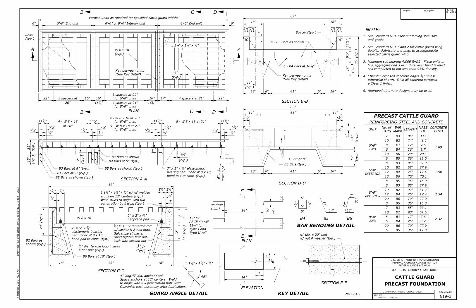
PRECAST CATTLE GUARD
REINFORCING STEEL AND CONCRETE
MARK
BAR
BARS
No. ofUNIT LENGTH
MASS CONCRETE
END
INTERIOR
INTERIOR
END
6
20
6
8
10
7
8
20
12
10
8
8
18
12
10
8
6
18
6
8
10
7
B5
B6
B4
B1
B2
B3
B5
B6
B4
B2
B3
B5
B6
B4
B2
B3
B5
B6
B4
B1
B2
B3
619-3
STANDARD APPROVED FOR USE 6/2005
DRAFT: 10/2016
REVISED:
CUYD
12.0
77.9
8.7
7.6
54.6
33.1
16.0
77.9
17.4
51.2
37.9
16.0
70.1
17.4
37.9
37.9
12.0
70.1
8.7
7.6
41.2
33.1
36"
70"
26"
17"
98"
85"
36"
70"
26"
92"
85"
36"
70"
26"
68"
85"
36"
70"
26"
17"
74"
85"
6'-0"
6'-0"
8'-0"
8'-0"2.32
2.34
1.90
1.89
STATE PROJECTNUMBER
SHEET
U.S. DEPARTMENT OF TRANSPORTATION
FEDERAL HIGHWAY ADMINISTRATION
]
US
C [
c:\m
yfiles\p
w_production\d
ms67488\Std
619-3.d
gn
7:24 A
M
4 O
cto
ber 2
016
FEDERAL LANDS HIGHWAY
U.S. CUSTOMARY STANDARD
STANDARD
PRECAST FOUNDATION
CATTLE GUARD
A
DCB
B C D
A
PLAN
B3 Bars as shown
B5 Bars as shown (typ.)
B5 Bars as shown (typ.)SECTION A-A
bond pad to conc. (typ.)
neoprene pad
SECTION C-C
GUARD ANGLE DETAIL
SECTION E-E
E
E
PLAN
ELEVATION
KEY DETAIL
B4
BAR BENDING DETAIL
B6B5
SECTION B-B
B5 Bars (typ.)
SECTION D-D
(See Key Detail)
Key between units
4 - B3 Bars as shown
Spacer (typ.)
(See Key Detail)
Key between units
Galvanize each assembly after fabrication.
to angle with full penetration butt weld.
w/ nut & washer (typ.)
5.
4.
3.
2.
1.
Approved alternate designs may be used.
a Class 1 finish.
otherwise shown. Give all concrete surfaces
soil compacted to not less than 95% density.
selected cattle guard wing.
details. Fabricate end units to accommodate
and grade.
penetration butt weld (typ.)
Weld studs to angle with full
(typ.)
LB
for 8'-0" units
4 spacers at 21" "8516
3 spacers at 20"
"2116
4 - W 8 x 18 at 20"
for 8'-0" units
5 - W 8 x 18 at 21"at 20"
B1 Bars at 9" (typ.)
B3 Bars at 8" (typ.)
B4 Bars at 9" (typ.)
W 8 x 18
Space anchors at 12" centers. Weld
bearing pad under W 8 x 18,
(ty
p.)
2"
studs on 12" centers (typ.).
" welded83" w/ 4
1" x 21" x 12
1L 1
"832" x 2" x
" dia. anchor stud.834" long
" dia. x 20" bolt43
" elastomeric837" x 5" x
"21115 - W 8 x 18 at 21""2
111for 6'-0" units"21114 - W 8 x 18"2
111
"215 "2
15 "215
(typ.)
"211
" unless 43Chamfer exposed concrete edges
20"
B6 Bars at 10" (typ.)
"41" x 2
1" x 121L 118"53"18"
fine aggregate bed 3 inch thick over hand leveled
Minimum soil bearing 4,000 lb/ft2. Place units in
See Standard 619-1 and 2 for cattle guard wing
See Standard 619-1 for reinforcing steel size
20" (ty
p.)
89"
"215"2
15"2
15"215
"83
" Ø A307 threaded rod43
"837" x 5" x
" dia. ferrule loop inserts43
(typ.)
11"
"41" x 2
1" x 121L 1
W 8 x 18
18"6"41"6"18"
14"61"14"
"215
89"
"215
3"
"215"2
15 "215"2
15
"2
111
"2
19
(ty
p.)
15"
36" (ty
p.)
(typ.)
4"
22"4 spacers at 21"17"16"for 6'-0" units16"16"3 spacers at22"
drain pip
e
6" m
in.
6"8'-0" End unit6'-0" or 8'-0" Interior unit6'-0" End unit6"
(ty
p.)
21"
(ty
p.)
15"
89"
18" 18"
18"6"41"6"18"
(ty
p.)
21"
(ty
p.)
15"
4"
"4310
8"
NOTE:
(typ.)
Rails
Furnish units as required for specified cattle guard widths
45°
(typ.)
4° draft
shown (typ.)
B2 Bars as
Type II rail
Type I and
ASCE 40 rail
Hand tighten first nut.
Galvanize all parts.
w/washer & 2-hex nuts.
Lock with second nutbond pad to conc. (typ.)
elastomeric bearing
4 per unit (typ.)
6 - B4 Bars at
3 - B3 at
14"
min."
41
1
6"
3"
14"
3"
5"
5"
"2
15
5"
"2
15
31"
14"
22"
7"
20"
12"
12"
36" (ty
p.)
"83
3"
12" for
" for2111
(typ.)
2" Clr.
pad under W 8 x 18
"215
"215
"21
"215
"21
"215
"21
"215
"21

NO SCALE
PRECAST CATTLE GUARD
REINFORCING STEEL AND CONCRETE
MARK
BAR
BARS
No. ofUNIT LENGTH
MASS CONCRETE
END
INTERIOR
INTERIOR
END
6
20
6
8
10
7
8
20
12
10
8
8
18
12
10
8
6
18
6
8
10
7
B5
B6
B4
B1
B2
B3
B5
B6
B4
B2
B3
B5
B6
B4
B2
B3
B5
B6
B4
B1
B2
B3
STANDARD APPROVED FOR USE 3/1996
DRAFT: 10/2016
REVISED: 11/1997 6/2005 619-3M
kg m³
1.40
1.41
1.73
1.72
5.4
34.8
3.9
3.4
24.4
14.6
7.2
34.8
7.8
22.4
16.7
7.2
31.3
7.8
16.4
16.7
5.4
31.3
3.9
3.4
18.4
14.6
900
1750
650
425
2450
2100
900
1750
650
2250
2100
900
1750
650
1650
2100
900
1750
650
425
1850
2100
1.8 m
1.8 m
2.4 m
2.4 m
STATE PROJECTNUMBER
SHEET
U.S. DEPARTMENT OF TRANSPORTATION
FEDERAL HIGHWAY ADMINISTRATION
]M
etric
[
c:\m
yfiles\p
w_production\d
ms67488\Std
619-3.d
gn
7:25 A
M
4 O
cto
ber 2
016
FEDERAL LANDS HIGHWAY
STANDARD
METRIC STANDARD
PRECAST FOUNDATION
CATTLE GUARD
A
DCB
B C D
A
PLAN
B3 Bars as shown
B5 Bars as shown (typ.)
B5 Bars as shown (typ.)SECTION A-A
bond pad to conc. (typ.)
neoprene pad
SECTION C-C
GUARD ANGLE DETAIL
SECTION E-E
E
E
PLAN
ELEVATION
KEY DETAIL
B4
BAR BENDING DETAIL
B6B5
SECTION B-B
B5 Bars (typ.)
SECTION D-D
(See Key Detail)
Key between units
4 - B3 Bars as shown
Spacer (typ.)
(See Key Detail)
Key between units
Galvanize each assembly after fabrication.
to angle with full penetration butt weld.
w/ nut & washer (typ.)
5.
4.
3.
2.
1.
Approved alternate designs may be used.
a Class 1 finish.
otherwise shown. Give all concrete surfaces
soil compacted to not less than 95% density.
selected cattle guard wing.
details. Fabricate end units to accommodate
and grade.
penetration butt weld (typ.)
Weld studs to angle with full
(typ.)
6.
bearing pad under W 200 x 27,
175 x 125 x 9.5 elastomeric
Space anchors at 300 centers. Weld
100 long M10 anchor stud.
3 spacers at 500
for 2.4 m units
4 - W 200 x 27 at 500
for 2.4 m units
M20 x 500 bolt
W 200 x 2750 x 50 x 9.5
studs on 300 centers (typ.).
L 38 x 38 x 6.4 w/M10 welded
B1 Bars at 225 (typ.)
B3 Bars at 200 (typ.)
B4 Bars at 225 (typ.)
L 38 x 38 x 6.4
B6 Bars at 250 (typ.)
Dimensions without units are millimeters.
Chamfer exposed concrete edges 20 mm unless
fine aggregate bed 75 mm thick over hand leveled
Minimum soil bearing 19,500 kg/m2. Place units in
See Standard M619-1 and 2 for cattle guard wing
See Standard M619-1 for reinforcing steel size
500 (ty
p.)
450 1325 450
140140
2225
10
140140
M20 A307 threaded rod
W 200 x 27
1502.4 m End unit1.8 m or 2.4 m interior unit1.8 m End unit150
L 38 x 38 x 6.4
140
(typ.)
35
drain pip
e
150 m
in.
140
300
5 - W 200 x 27 at 525
300
5 - W 200 x 27 at 525
for 1.8 m units
300
at 500
4 - W 200 x 27
300
140
(ty
p.)
50
pad under W 200 x 27
175 x 125 x 9.5
M20 ferrule loop inserts
290 for
305 for
200
4501501025150450
(ty
p.)
375
(ty
p.)
525
100
140
3501525350
140
2225
275
900 (ty
p.)
(ty
p.)
375
235
290
4501501025150450
450
75
450
(typ.)
100
140140 140140
2225
NOTE:
(typ.)
Rails
Furnish units as required for specified cattle guard widths
45°
(typ.)
4° draft
shown (typ.)
B2 Bars as
Type II rail
Type I and
ASCE 40 rail
Hand tighten first nut.
Galvanize all parts.
w/washer & 2-hex nuts.
Lock with second nutbond pad to conc. (typ.)
elastomeric bearing
4 per unit (typ.)
6 - B4 Bars at
3 - B3 at
14020
140140
20140
20140
20
300
350
751507
5
350
125
125
550
350 300
500
175
775
125
10
75
550
4 spacers at 525
425
415
400
4 spacers at 525
for 1.8 m units
410
400
400
500
3 spacers at
550
(ty
p.)
525
(ty
p.)
375
900 (ty
p.)
(typ.)
50 Clr.
min.
30
135
135
(typ.)
280