Embed Size (px)
Citation preview

MAE 6530 - Propulsion Systems II
Section 5.2: The TurboJet Propulsion CycleMassflow Matching Requirements
1
MAE 6530 - Propulsion Systems II
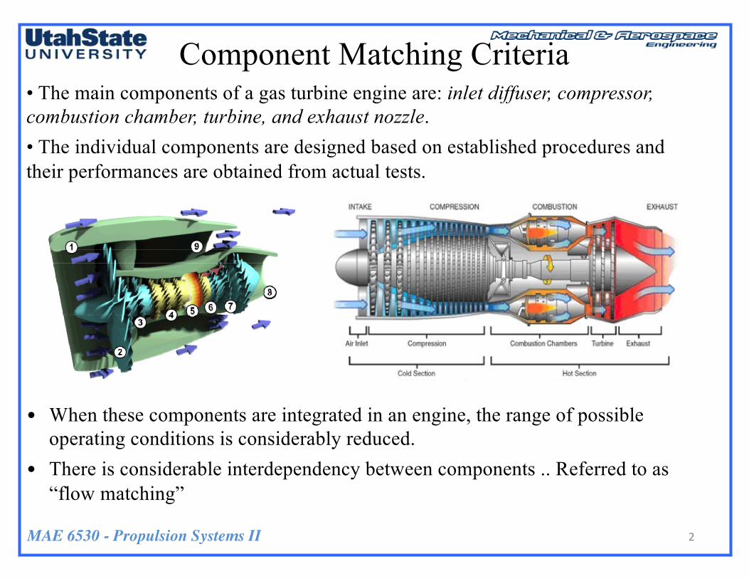
• The main components of a gas turbine engine are: inlet diffuser, compressor, combustion chamber, turbine, and exhaust nozzle. • The individual components are designed based on established procedures and their performances are obtained from actual tests.
• When these components are integrated in an engine, the range of possible operating conditions is considerably reduced.
• There is considerable interdependency between components .. Referred to as “flow matching”
Component Matching Criteria
2
MAE 6530 - Propulsion Systems II
Turbine/Nozzle Flow Matching
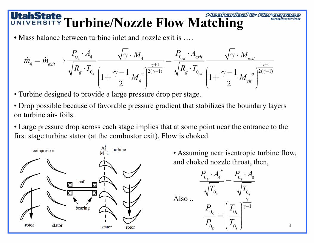
• Turbine designed to provide a large pressure drop per stage. • Drop possible because of favorable pressure gradient that stabilizes the boundary layers on turbine air- foils. • Large pressure drop across each stage implies that at some point near the entrance to the first stage turbine stator (at the combustor exit), Flow is choked.
• Assuming near isentropic turbine flow, and choked nozzle throat, then,
Also ..
P04 ⋅ A4*
T04=P08 ⋅ A8T08
P05P08=T05T08
⎛
⎝
⎜⎜⎜⎜⎜
⎞
⎠
⎟⎟⎟⎟⎟⎟
γγ−1
• Mass balance between turbine inlet and nozzle exit is ….
!m4 = !mexit→P04 ⋅ A4Rg ⋅T04
γ ⋅M4
1+ γ−12M4
2⎛
⎝⎜⎜⎜
⎞
⎠⎟⎟⎟⎟
γ+12(γ−1)
=P0eit ⋅ AexitRg ⋅T0eit
γ ⋅Mexit
1+ γ−12Meit
2⎛
⎝⎜⎜⎜
⎞
⎠⎟⎟⎟⎟
γ+12(γ−1)
3
MAE 6530 - Propulsion Systems II
Turbine/Nozzle Flow Matching(2)
P04 ⋅ A4*
T04=P08 ⋅ A8T08
P05P08=T05T08
⎛
⎝
⎜⎜⎜⎜⎜
⎞
⎠
⎟⎟⎟⎟⎟⎟
γγ−1
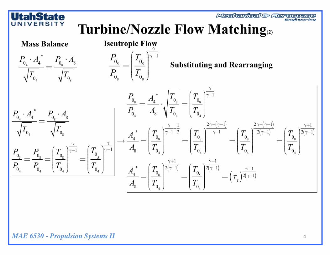
Mass Balance Isentropic Flow
Substituting and Rearranging
P04 ⋅ A4*
T04=P08 ⋅ A8T08
P05P04=P08P04=T08T04
⎛
⎝
⎜⎜⎜⎜⎜
⎞
⎠
⎟⎟⎟⎟⎟⎟
γγ−1
=T0
5
T04
⎛
⎝
⎜⎜⎜⎜⎜
⎞
⎠
⎟⎟⎟⎟⎟⎟
γγ−1→
P08P04=A4*
A8⋅T08T04=T08T04
⎛
⎝
⎜⎜⎜⎜⎜
⎞
⎠
⎟⎟⎟⎟⎟⎟
γγ−1
A4*
A8=T08T04
⎛
⎝
⎜⎜⎜⎜⎜
⎞
⎠
⎟⎟⎟⎟⎟⎟
γγ−1−12
=T08T04
⎛
⎝
⎜⎜⎜⎜⎜
⎞
⎠
⎟⎟⎟⎟⎟⎟
2γ− γ−1( )γ−1
=T08T04
⎛
⎝
⎜⎜⎜⎜⎜
⎞
⎠
⎟⎟⎟⎟⎟⎟
2γ− γ−1( )2 γ−1( )
=T08T04
⎛
⎝
⎜⎜⎜⎜⎜
⎞
⎠
⎟⎟⎟⎟⎟⎟
γ+12 γ−1( )
A4*
A8=T08T04
⎛
⎝
⎜⎜⎜⎜⎜
⎞
⎠
⎟⎟⎟⎟⎟⎟
γ+12 γ−1( )=T05T04
⎛
⎝
⎜⎜⎜⎜⎜
⎞
⎠
⎟⎟⎟⎟⎟⎟
γ+12 γ−1( )= τt( )
γ+12 γ−1( )
4
MAE 6530 - Propulsion Systems II
Turbine/Nozzle Flow Matching (2)
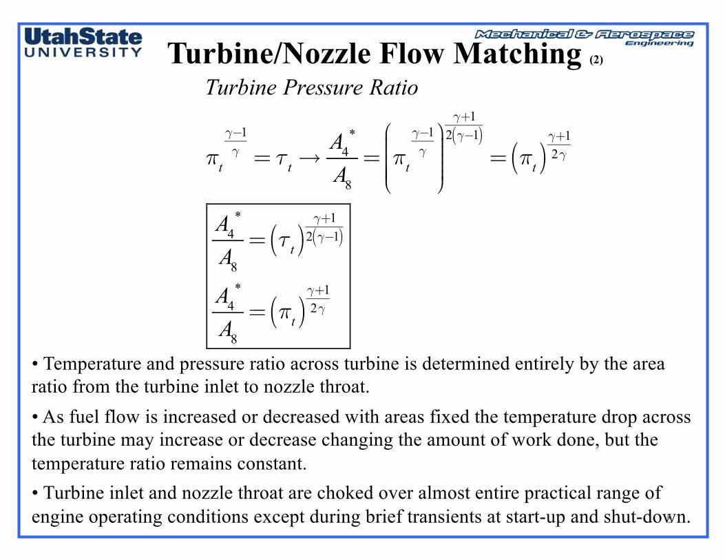
• Temperature and pressure ratio across turbine is determined entirely by the area ratio from the turbine inlet to nozzle throat. • As fuel flow is increased or decreased with areas fixed the temperature drop across the turbine may increase or decrease changing the amount of work done, but the temperature ratio remains constant. • Turbine inlet and nozzle throat are choked over almost entire practical range of engine operating conditions except during brief transients at start-up and shut-down.
Turbine Pressure Ratio
πt
γ−1γ = τt→
A4*
A8
= πt
γ−1γ
⎛
⎝
⎜⎜⎜⎜⎜
⎞
⎠
⎟⎟⎟⎟⎟
γ+12 γ−1( )= πt( )
γ+12γ
A4*
A8
= τt( )γ+1
2 γ−1( )
A4*
A8
= πt( )γ+12γ
5
MAE 6530 - Propulsion Systems II
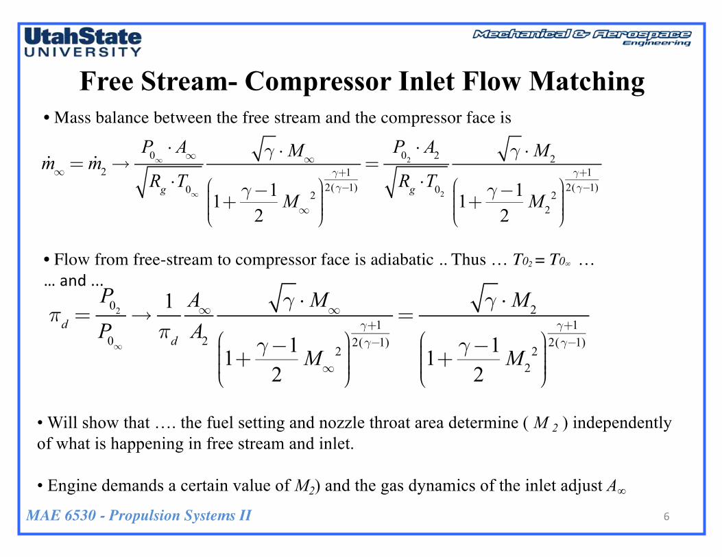
Free Stream- Compressor Inlet Flow Matching• Mass balance between the free stream and the compressor face is
• Flow from free-stream to compressor face is adiabatic .. Thus … T02 = T0∞ ……and...
πd =P02P0∞→1πd
A∞A2
γ ⋅M∞
1+ γ−12M∞
2⎛
⎝⎜⎜⎜
⎞
⎠⎟⎟⎟⎟
γ+12(γ−1)
=γ ⋅M2
1+ γ−12M2
2⎛
⎝⎜⎜⎜
⎞
⎠⎟⎟⎟⎟
γ+12(γ−1)
• Will show that …. the fuel setting and nozzle throat area determine ( M 2 ) independently of what is happening in free stream and inlet.
• Engine demands a certain value of M2) and the gas dynamics of the inlet adjust A∞
!m∞ = !m2→P0∞ ⋅ A∞Rg ⋅T0∞
γ ⋅M∞
1+ γ−12M∞
2⎛
⎝⎜⎜⎜
⎞
⎠⎟⎟⎟⎟
γ+12(γ−1)
=P02 ⋅ A2Rg ⋅T02
γ ⋅M2
1+ γ−12M2
2⎛
⎝⎜⎜⎜
⎞
⎠⎟⎟⎟⎟
γ+12(γ−1)
6

MAE 6530 - Propulsion Systems II
Free Stream- Compressor Inlet Flow Matching (2)
A∞ A∞
A∞ A∞
A∞ A∞
7
MAE 6530 - Propulsion Systems II
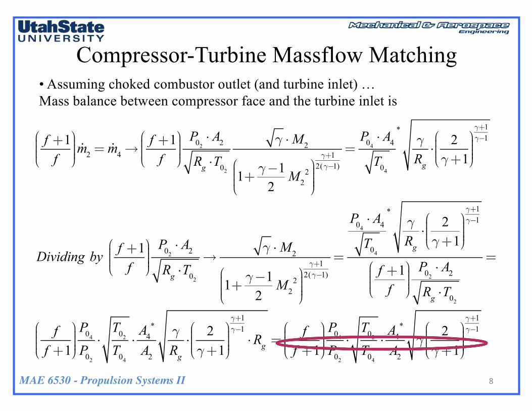
Compressor-Turbine Massflow Matching• Assuming choked combustor outlet (and turbine inlet) … Mass balance between compressor face and the turbine inlet is
f +1f
⎛
⎝⎜⎜⎜
⎞
⎠⎟⎟⎟⎟!m2 = !m4→
f +1f
⎛
⎝⎜⎜⎜
⎞
⎠⎟⎟⎟⎟P02 ⋅ A2Rg ⋅T02
γ ⋅M2
1+ γ−12M2
2⎛
⎝⎜⎜⎜
⎞
⎠⎟⎟⎟⎟
γ+12(γ−1)
=P04 ⋅ A4T04
*γRg⋅2γ+1⎛
⎝⎜⎜⎜
⎞
⎠⎟⎟⎟⎟
γ+1γ−1
Dividing by f +1f
⎛
⎝⎜⎜⎜
⎞
⎠⎟⎟⎟⎟P02⋅ A2
Rg ⋅T02
→γ ⋅M2
1+ γ−12M2
2⎛
⎝⎜⎜⎜
⎞
⎠⎟⎟⎟⎟
γ+12(γ−1)
=
P04⋅ A4
T04
*γRg⋅
2γ+1⎛
⎝⎜⎜⎜
⎞
⎠⎟⎟⎟⎟
γ+1γ−1
f +1f
⎛
⎝⎜⎜⎜
⎞
⎠⎟⎟⎟⎟P02⋅ A2
Rg ⋅T02
=
ff +1⎛
⎝⎜⎜⎜
⎞
⎠⎟⎟⎟⎟P04
P02
⋅T02
T04
⋅A4
*
A2
γRg⋅
2γ+1⎛
⎝⎜⎜⎜
⎞
⎠⎟⎟⎟⎟
γ+1γ−1⋅Rg =
ff +1⎛
⎝⎜⎜⎜
⎞
⎠⎟⎟⎟⎟P04
P02
⋅T02
T04
⋅A4
*
A2
γ2γ+1⎛
⎝⎜⎜⎜
⎞
⎠⎟⎟⎟⎟
γ+1γ−1
8
MAE 6530 - Propulsion Systems II
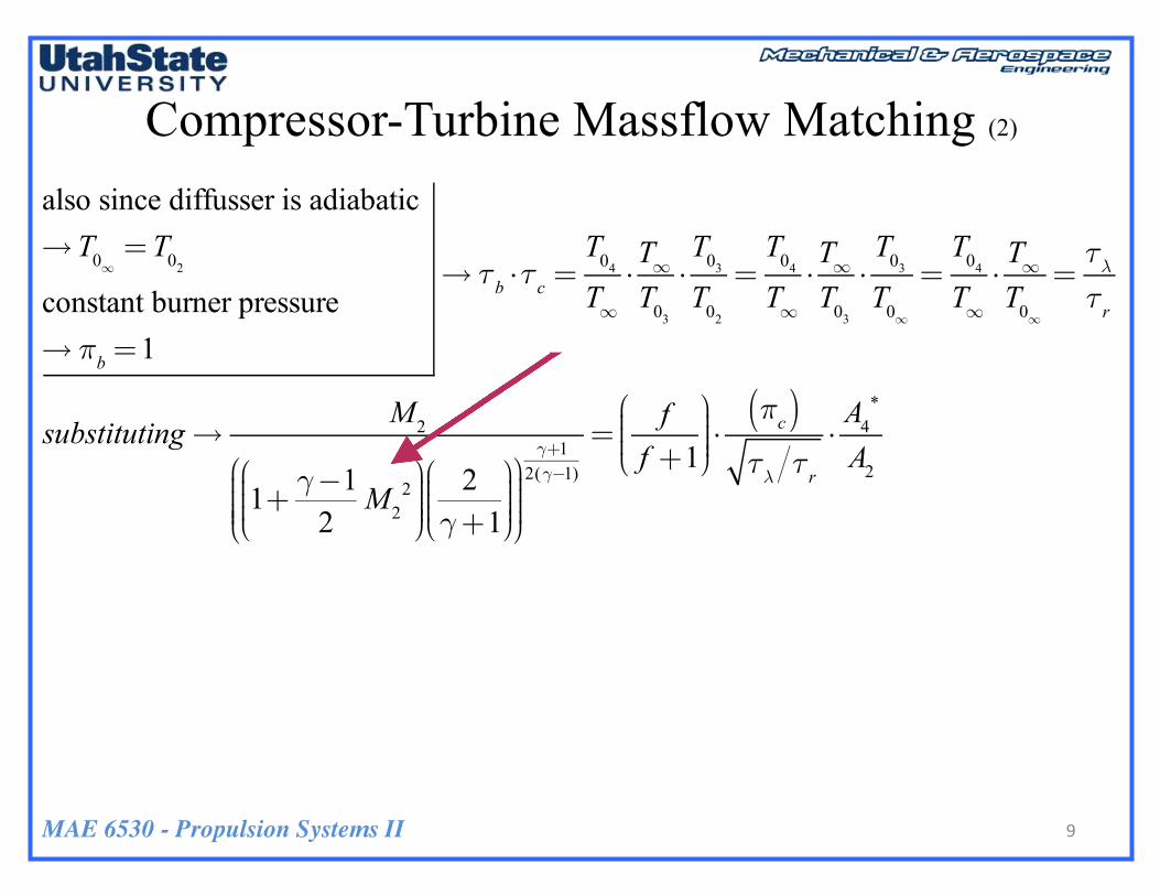
Compressor-Turbine Massflow Matching (2)
also since diffusser is adiabatic →T0∞
=T02
constant burner pressure→ πb =1
→ τb ⋅τc =T04
T∞⋅T∞T03
⋅T03
T02
=T04
T∞⋅T∞T03
⋅T03
T0∞
=T04
T∞⋅T∞T0∞
=τλτr
substituting→M2
1+ γ−12M2
2⎛
⎝⎜⎜⎜
⎞
⎠⎟⎟⎟⎟
2γ+1
⎛
⎝⎜⎜⎜
⎞
⎠⎟⎟⎟⎟
⎛
⎝⎜⎜⎜⎜
⎞
⎠⎟⎟⎟⎟
γ+12(γ−1)
=ff +1
⎛
⎝⎜⎜⎜
⎞
⎠⎟⎟⎟⎟⋅πc( )τλ τr
⋅A4
*
A2
9
MAE 6530 - Propulsion Systems II
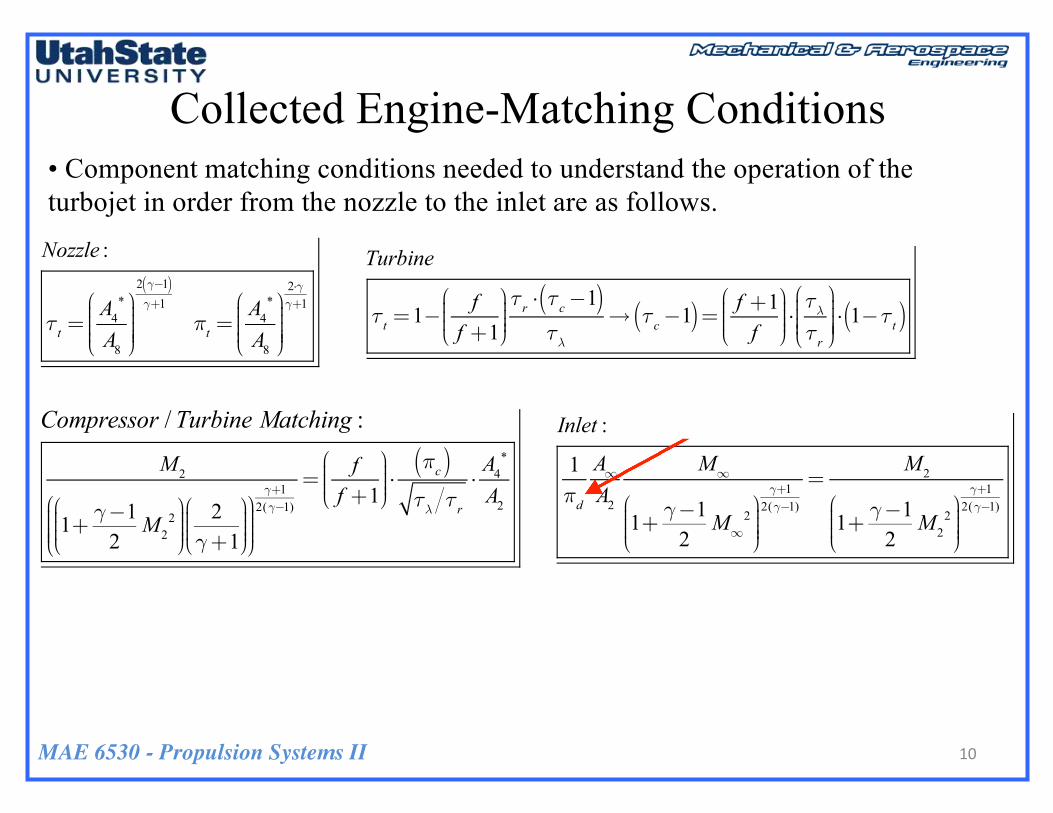
Collected Engine-Matching Conditions • Component matching conditions needed to understand the operation of the turbojet in order from the nozzle to the inlet are as follows.
Nozzle :
τt =A4
*
A8
⎛
⎝⎜⎜⎜⎜
⎞
⎠⎟⎟⎟⎟⎟
2 γ−1( )γ+1
πt =A4
*
A8
⎛
⎝⎜⎜⎜⎜
⎞
⎠⎟⎟⎟⎟⎟
2⋅γγ+1
Turbine
τt =1− ff +1⎛
⎝⎜⎜⎜
⎞
⎠⎟⎟⎟⎟τr ⋅ τc−1( )τλ
→ τc−1( )= f +1f
⎛
⎝⎜⎜⎜
⎞
⎠⎟⎟⎟⎟⋅τλτr
⎛
⎝⎜⎜⎜⎜
⎞
⎠⎟⎟⎟⎟⎟⋅ 1−τt( )
Compressor :
M2
1+ γ−12M2
2⎛
⎝⎜⎜⎜
⎞
⎠⎟⎟⎟⎟
2γ+1⎛
⎝⎜⎜⎜
⎞
⎠⎟⎟⎟⎟
⎛
⎝⎜⎜⎜⎜
⎞
⎠⎟⎟⎟⎟
γ+12(γ−1)
=ff +1⎛
⎝⎜⎜⎜
⎞
⎠⎟⎟⎟⎟⋅πc( )τλ τr
⋅A4
*
A2
Inlet :
1πd
A∞A2
M∞
1+ γ−12M∞
2⎛
⎝⎜⎜⎜
⎞
⎠⎟⎟⎟⎟
γ+12(γ−1)
=M2
1+ γ−12M2
2⎛
⎝⎜⎜⎜
⎞
⎠⎟⎟⎟⎟
γ+12(γ−1)
10
Compressor / Turbine Matching :
MAE 6530 - Propulsion Systems II
Effect of Afterburning
11
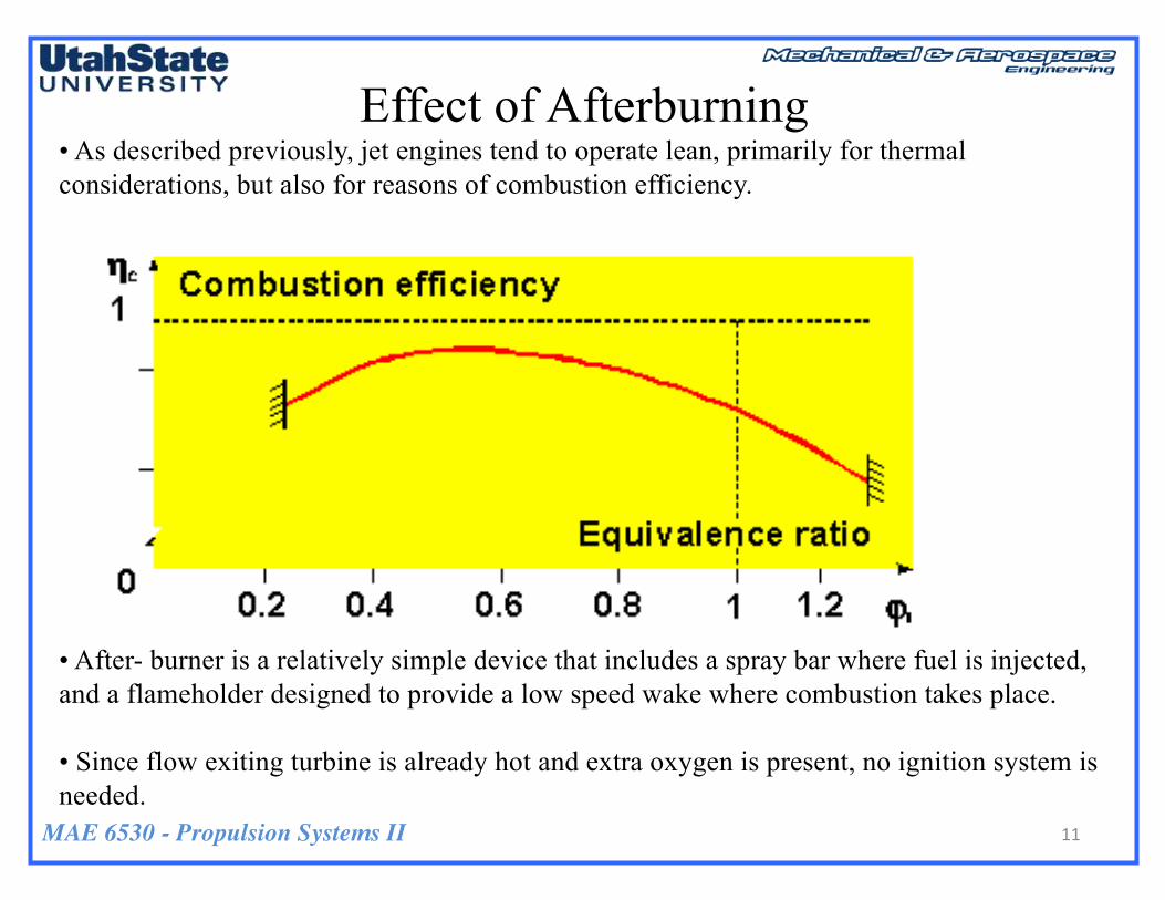
• As described previously, jet engines tend to operate lean, primarily for thermal considerations, but also for reasons of combustion efficiency.
• After- burner is a relatively simple device that includes a spray bar where fuel is injected, and a flameholder designed to provide a low speed wake where combustion takes place.
• Since flow exiting turbine is already hot and extra oxygen is present, no ignition system is needed.

MAE 6530 - Propulsion Systems II
Effect of Afterburning (2)
• Additional fuel is introduced into the hot exhaust and burned using excessO2 from main combustion
• The afterburner increases the temperature of the gas ahead of the nozzle Increases exit velocity
• The result of this increase in temperature is an increase of about 40 percent in thrust at takeoff and a much larger percentage at high speeds
MAE 6530 - Propulsion Systems II
Effect of Afterburning (3)
13
•
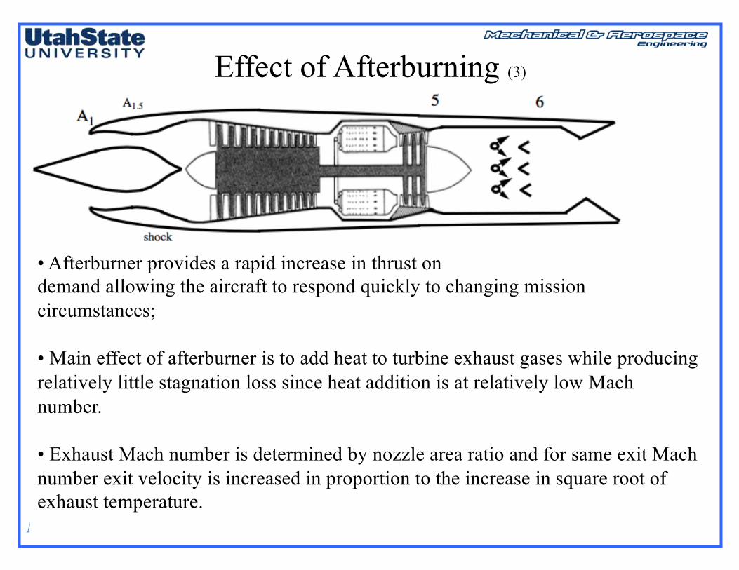
• Afterburner provides a rapid increase in thrust on demand allowing the aircraft to respond quickly to changing mission circumstances;
• Main effect of afterburner is to add heat to turbine exhaust gases while producing relatively little stagnation loss since heat addition is at relatively low Mach number.
• Exhaust Mach number is determined by nozzle area ratio and for same exit Mach number exit velocity is increased in proportion to the increase in square root of exhaust temperature.
MAE 6530 - Propulsion Systems II
Effect of Afterburning (4)
14
•
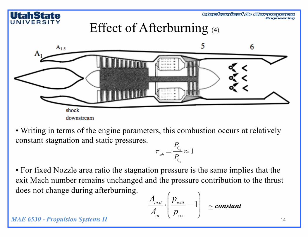
• Writing in terms of the engine parameters, this combustion occurs at relatively constant stagnation and static pressures.
• For fixed Nozzle area ratio the stagnation pressure is the same implies that the exit Mach number remains unchanged and the pressure contribution to the thrust does not change during afterburning.
πab =P06P05≈1
AexitA∞⋅pexitp∞−1
⎛
⎝⎜⎜⎜⎜
⎞
⎠⎟⎟⎟⎟⎟
~ constant
MAE 6530 - Propulsion Systems II
Effect of Afterburning (5)
15
•
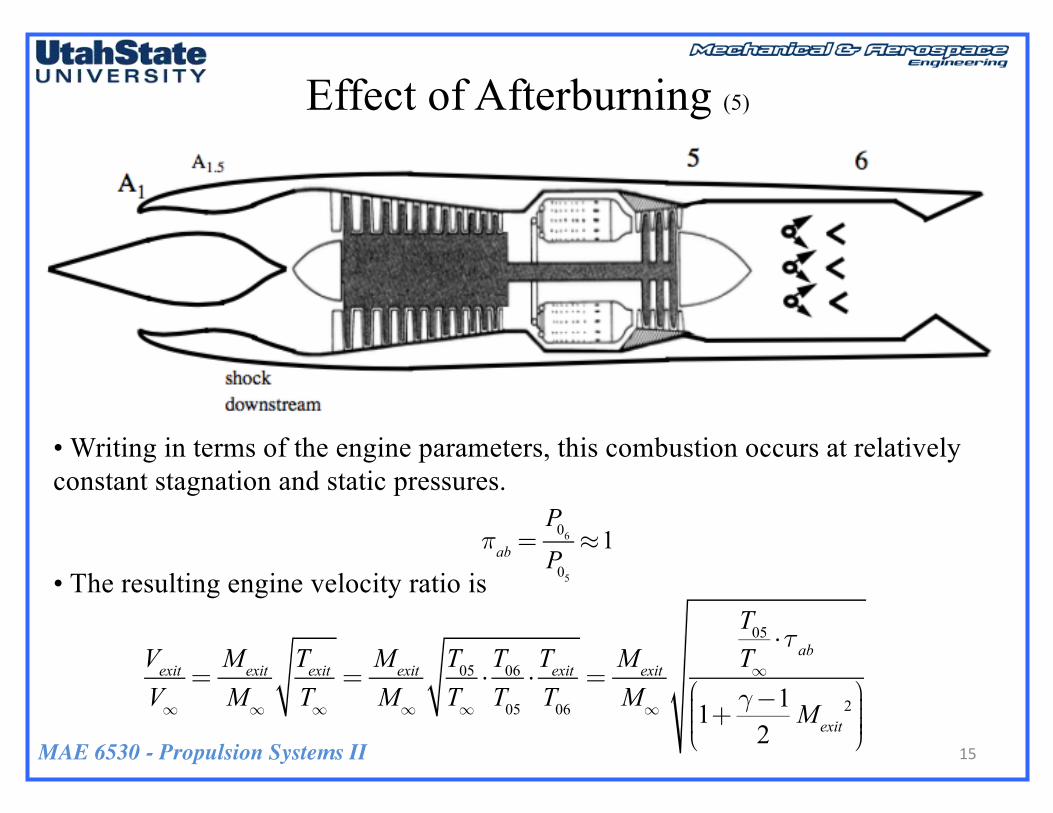
• Writing in terms of the engine parameters, this combustion occurs at relatively constant stagnation and static pressures.
• The resulting engine velocity ratio isπab =
P06P05≈1
VexitV∞=Mexit
M∞
TexitT∞=Mexit
M∞
T05T∞⋅T06T05⋅TexitT06=Mexit
M∞
T05T∞⋅τab
1+ γ−12Mexit
2⎛
⎝⎜⎜⎜
⎞
⎠⎟⎟⎟⎟
MAE 6530 - Propulsion Systems II
Effect of Afterburning (6)
16
•
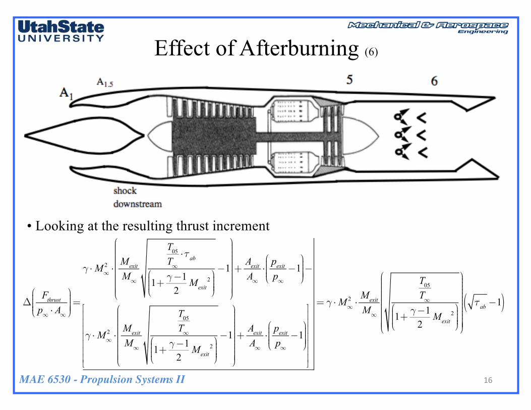
• Looking at the resulting thrust increment
ΔFthrustp∞ ⋅ A∞
⎛
⎝⎜⎜⎜⎜
⎞
⎠⎟⎟⎟⎟⎟=
γ ⋅M∞2 ⋅Mexit
M∞
T05T∞⋅τab
1+ γ−12Mexit
2⎛
⎝⎜⎜⎜
⎞
⎠⎟⎟⎟⎟
−1
⎛
⎝
⎜⎜⎜⎜⎜⎜⎜⎜⎜⎜⎜⎜
⎞
⎠
⎟⎟⎟⎟⎟⎟⎟⎟⎟⎟⎟⎟⎟⎟
+AexitA∞⋅pexitp∞−1
⎛
⎝⎜⎜⎜⎜
⎞
⎠⎟⎟⎟⎟⎟−
γ ⋅M∞2 ⋅Mexit
M∞
T05T∞
1+ γ−12Mexit
2⎛
⎝⎜⎜⎜
⎞
⎠⎟⎟⎟⎟
−1
⎛
⎝
⎜⎜⎜⎜⎜⎜⎜⎜⎜⎜⎜⎜
⎞
⎠
⎟⎟⎟⎟⎟⎟⎟⎟⎟⎟⎟⎟⎟⎟
+AexitA∞⋅pexitp∞−1
⎛
⎝⎜⎜⎜⎜
⎞
⎠⎟⎟⎟⎟⎟
⎡
⎣
⎢⎢⎢⎢⎢⎢⎢
⎤
⎦
⎥⎥⎥⎥⎥⎥⎥
= γ ⋅M∞2 ⋅Mexit
M∞
T05T∞
1+ γ−12Mexit
2⎛
⎝⎜⎜⎜
⎞
⎠⎟⎟⎟⎟
⎛
⎝
⎜⎜⎜⎜⎜⎜⎜⎜⎜⎜⎜⎜
⎞
⎠
⎟⎟⎟⎟⎟⎟⎟⎟⎟⎟⎟⎟⎟⎟
τab −1( )
MAE 6530 - Propulsion Systems II
Effect of Afterburning (7)
17
•
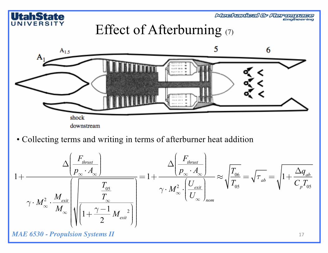
• Collecting terms and writing in terms of afterburner heat addition
1+Δ
Fthrustp∞ ⋅ A∞
⎛
⎝⎜⎜⎜⎜
⎞
⎠⎟⎟⎟⎟
γ ⋅M∞2 ⋅Mexit
M∞
T05T∞
1+ γ−12Mexit
2⎛
⎝⎜⎜⎜
⎞
⎠⎟⎟⎟⎟
⎛
⎝
⎜⎜⎜⎜⎜⎜⎜⎜⎜⎜⎜⎜
⎞
⎠
⎟⎟⎟⎟⎟⎟⎟⎟⎟⎟⎟⎟⎟
=1+Δ
Fthrustp∞ ⋅ A∞
⎛
⎝⎜⎜⎜⎜
⎞
⎠⎟⎟⎟⎟
γ ⋅M∞2 ⋅Uexit
U∞
⎛
⎝⎜⎜⎜⎜
⎞
⎠⎟⎟⎟⎟nom
≈T06T05= τab = 1+
ΔqabCpT05
MAE 6530 - Propulsion Systems II
Effect of Afterburning (8)
18
•
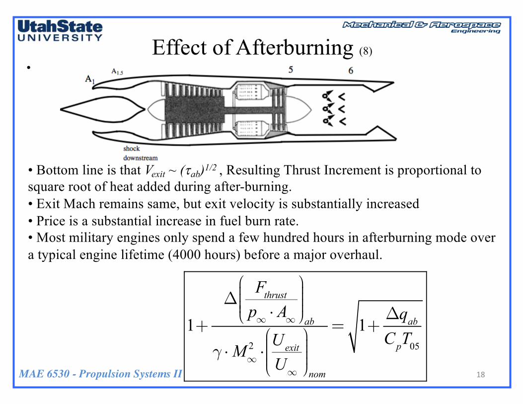
• Bottom line is that Vexit ~ (tab)1/2 , Resulting Thrust Increment is proportional to square root of heat added during after-burning. • Exit Mach remains same, but exit velocity is substantially increased • Price is a substantial increase in fuel burn rate. • Most military engines only spend a few hundred hours in afterburning mode over a typical engine lifetime (4000 hours) before a major overhaul.
1+Δ
Fthrustp∞ ⋅ A∞
⎛
⎝⎜⎜⎜⎜
⎞
⎠⎟⎟⎟⎟ab
γ ⋅M∞2 ⋅Uexit
U∞
⎛
⎝⎜⎜⎜⎜
⎞
⎠⎟⎟⎟⎟nom
= 1+ΔqabCpT05
MAE 6530 - Propulsion Systems II
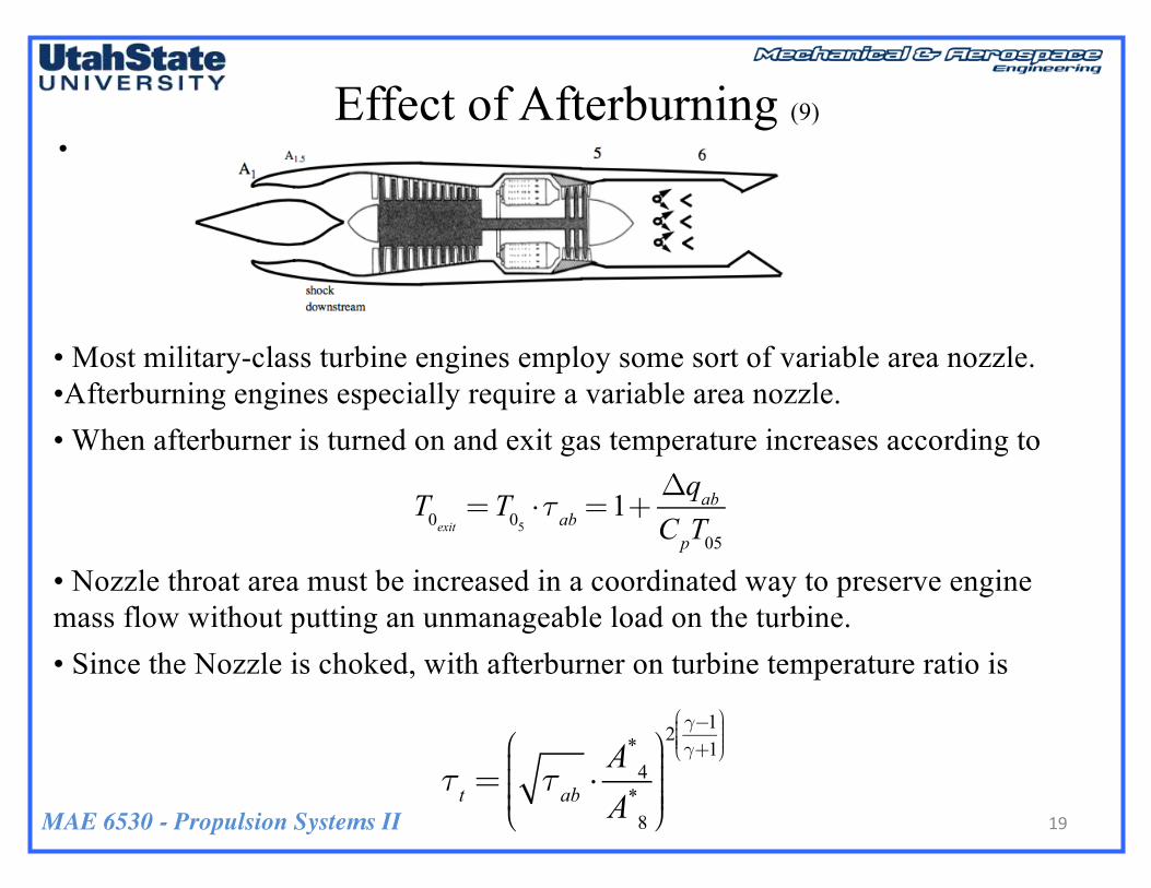
• Most military-class turbine engines employ some sort of variable area nozzle. •Afterburning engines especially require a variable area nozzle. • When afterburner is turned on and exit gas temperature increases according to
• Nozzle throat area must be increased in a coordinated way to preserve engine mass flow without putting an unmanageable load on the turbine.• Since the Nozzle is choked, with afterburner on turbine temperature ratio is
Effect of Afterburning (9)
19
•
T0exit =T05 ⋅τab =1+ΔqabCpT05
τt = τab ⋅A*4A*8
⎛
⎝⎜⎜⎜⎜
⎞
⎠⎟⎟⎟⎟⎟
2 γ−1γ+1⎛
⎝⎜⎜⎜⎜
⎞
⎠⎟⎟⎟⎟
MAE 6530 - Propulsion Systems II
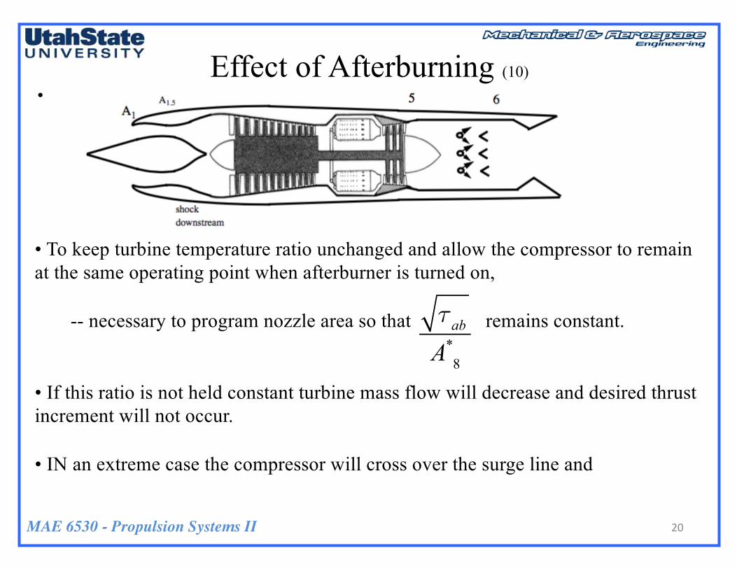
• To keep turbine temperature ratio unchanged and allow the compressor to remain at the same operating point when afterburner is turned on,
-- necessary to program nozzle area so that remains constant.
• If this ratio is not held constant turbine mass flow will decrease and desired thrust increment will not occur.
• IN an extreme case the compressor will cross over the surge line and
Effect of Afterburning (10)
20
•
τabA*8

MAE 6530 - Propulsion Systems II
Effect of Afterburning (11)
21
Credit:Chalmer sUniversityoftechnology
Sukhoi Su-35S Thrust Vectored Variable Area Nozzle (Russian)
MAE 6530 - Propulsion Systems II
Collected Engine-Matching Conditions (Updated)
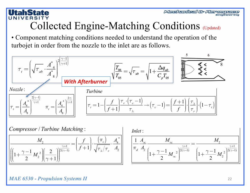
• Component matching conditions needed to understand the operation of the turbojet in order from the nozzle to the inlet are as follows.
Nozzle :
τt =A4
*
A8
⎛
⎝⎜⎜⎜⎜
⎞
⎠⎟⎟⎟⎟⎟
2 γ−1( )γ+1
πt =A4
*
A8
⎛
⎝⎜⎜⎜⎜
⎞
⎠⎟⎟⎟⎟⎟
2⋅γγ+1
Turbine
τt =1− ff +1⎛
⎝⎜⎜⎜
⎞
⎠⎟⎟⎟⎟τr ⋅ τc−1( )τλ
→ τc−1( )= f +1f
⎛
⎝⎜⎜⎜
⎞
⎠⎟⎟⎟⎟⋅τλτr
⎛
⎝⎜⎜⎜⎜
⎞
⎠⎟⎟⎟⎟⎟⋅ 1−τt( )
Compressor :
M2
1+ γ−12M2
2⎛
⎝⎜⎜⎜
⎞
⎠⎟⎟⎟⎟
2γ+1⎛
⎝⎜⎜⎜
⎞
⎠⎟⎟⎟⎟
⎛
⎝⎜⎜⎜⎜
⎞
⎠⎟⎟⎟⎟
γ+12(γ−1)
=ff +1⎛
⎝⎜⎜⎜
⎞
⎠⎟⎟⎟⎟⋅πc( )τλ τr
⋅A4
*
A2
Inlet :
1πd
A∞A2
M∞
1+ γ−12M∞
2⎛
⎝⎜⎜⎜
⎞
⎠⎟⎟⎟⎟
γ+12(γ−1)
=M2
1+ γ−12M2
2⎛
⎝⎜⎜⎜
⎞
⎠⎟⎟⎟⎟
γ+12(γ−1)
22
Compressor / Turbine Matching :
τt = τab ⋅A*4A*8
⎛
⎝⎜⎜⎜⎜
⎞
⎠⎟⎟⎟⎟⎟
2 γ−1γ+1⎛
⎝⎜⎜⎜⎜
⎞
⎠⎟⎟⎟⎟
WithAfterburner
8
MAE 6530 - Propulsion Systems II
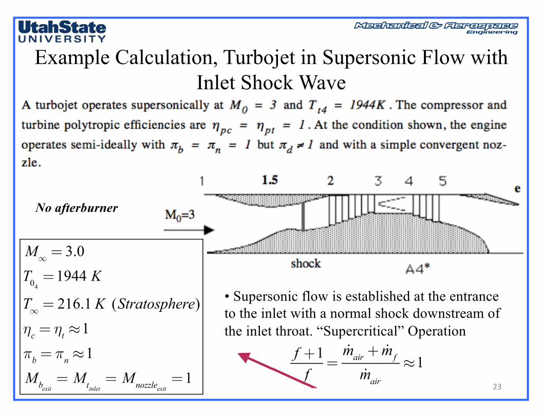
Example Calculation, Turbojet in Supersonic Flow with Inlet Shock Wave
• Supersonic flow is established at the entrance to the inlet with a normal shock downstream of the inlet throat. “Supercritical” Operation
23
M∞ = 3.0T04=1944 K
T∞ = 216.1 K (Stratosphere)ηc = ηt ≈1πb = πn ≈1Mbexit
= Mtinlet= Mnozzleexit
=1f +1f=!mair + !mf
!mair≈1
No afterburner
MAE 6530 - Propulsion Systems II
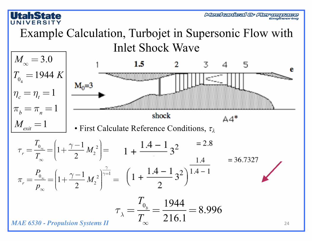
Example Calculation, Turbojet in Supersonic Flow with Inlet Shock Wave
• First Calculate Reference Conditions, tl
M∞ = 3.0T04=1944 K
ηc = ηt =1πb = πn =1Mexit =1
24
τr =T0∞T∞= 1+ γ−1
2M2
2⎛
⎝⎜⎜⎜
⎞
⎠⎟⎟⎟⎟=
πr =P0∞p∞= 1+ γ−1
2M2
2⎛
⎝⎜⎜⎜
⎞
⎠⎟⎟⎟⎟
γγ=1=
τλ =T0bT∞=1944216.1
= 8.996
MAE 6530 - Propulsion Systems II
Example Calculation, Turbojet in Supersonic Flow with Inlet Shock Wave (2)
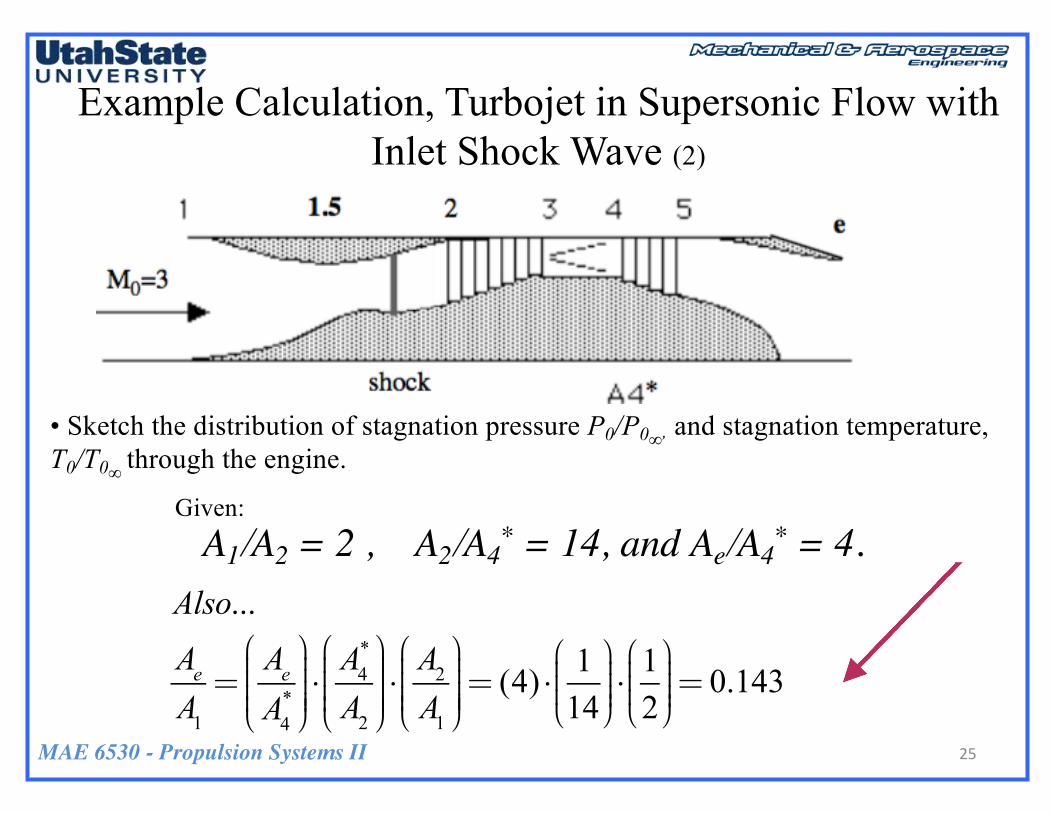
• Sketch the distribution of stagnation pressure P0/P0∞, and stagnation temperature, T0/T0∞ through the engine.
A1/A2 = 2 , A2/A4* = 14, and Ae/A4
* = 4. Also...
AeA1=AeA4*
⎛
⎝⎜⎜⎜⎜
⎞
⎠⎟⎟⎟⎟⎟⋅A4*
A2
⎛
⎝⎜⎜⎜⎜
⎞
⎠⎟⎟⎟⎟⎟⋅A2A1
⎛
⎝⎜⎜⎜⎜
⎞
⎠⎟⎟⎟⎟⎟= (4) ⋅ 1
14⎛
⎝⎜⎜⎜⎞
⎠⎟⎟⎟⎟⋅12⎛
⎝⎜⎜⎜⎞
⎠⎟⎟⎟⎟= 0.143
Given:
25
MAE 6530 - Propulsion Systems II
Example Calculation, Turbojet in Supersonic Flow with Inlet Shock Wave (3)
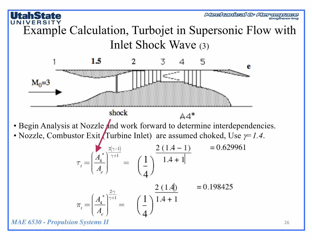
• Begin Analysis at Nozzle and work forward to determine interdependencies. • Nozzle, Combustor Exit (Turbine Inlet) are assumed choked, Use g=1.4.
τt =A4
*
Ae
⎛
⎝⎜⎜⎜⎜
⎞
⎠⎟⎟⎟⎟⎟
2 γ−1( )γ+1
=
πt =A4
*
Ae
⎛
⎝⎜⎜⎜⎜
⎞
⎠⎟⎟⎟⎟⎟
2⋅γγ+1
=
26
MAE 6530 - Propulsion Systems II
Example Calculation, Turbojet in Supersonic Flow with Inlet Shock Wave (4)
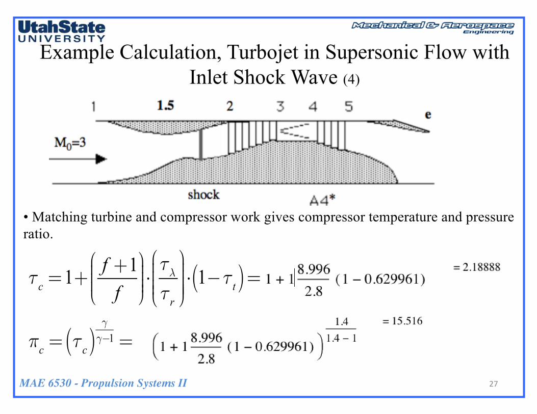
• Matching turbine and compressor work gives compressor temperature and pressure ratio.
27
τc =1+f +1f
⎛
⎝⎜⎜⎜
⎞
⎠⎟⎟⎟⎟⋅τλτr
⎛
⎝⎜⎜⎜⎜
⎞
⎠⎟⎟⎟⎟⎟⋅ 1−τt( )=
πc = τc( )γγ−1 =

MAE 6530 - Propulsion Systems II
Example Calculation, Turbojet in Supersonic Flow with Inlet Shock Wave (5)
• Now Calculate Mach Number at Compressor Face
28
→ M2 = 0.392
MAE 6530 - Propulsion Systems II
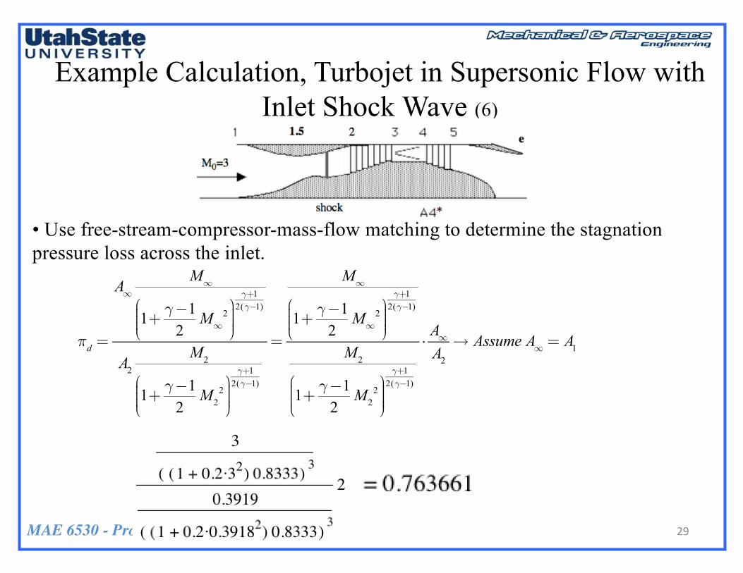
• Use free-stream-compressor-mass-flow matching to determine the stagnation pressure loss across the inlet.
Example Calculation, Turbojet in Supersonic Flow with Inlet Shock Wave (6)
29
πd =
A∞M∞
1+ γ−12M∞
2⎛
⎝⎜⎜⎜
⎞
⎠⎟⎟⎟⎟
γ+12(γ−1)
A2
M2
1+ γ−12M2
2⎛
⎝⎜⎜⎜
⎞
⎠⎟⎟⎟⎟
γ+12(γ−1)
=
M∞
1+ γ−12M∞
2⎛
⎝⎜⎜⎜
⎞
⎠⎟⎟⎟⎟
γ+12(γ−1)
M2
1+ γ−12M2
2⎛
⎝⎜⎜⎜
⎞
⎠⎟⎟⎟⎟
γ+12(γ−1)
⋅A∞A2
→ Assume A∞ = A1

MAE 6530 - Propulsion Systems II
• Calculate the Stagnation Pressure Ratio Across Engine
• Calculate Static Pressure Ratio Across Engine
Example Calculation, Turbojet in Supersonic Flow with Inlet Shock Wave (7)
30
pexitp∞=P0exit 1+ γ−1
2Mexit
2⎛
⎝⎜⎜⎜
⎞
⎠⎟⎟⎟⎟
γ(γ−1)
P0∞ 1+ γ−12M∞
2⎛
⎝⎜⎜⎜
⎞
⎠⎟⎟⎟⎟
γ(γ−1)
=

MAE 6530 - Propulsion Systems II
• Calculate the Stagnation Temperature Ratio Across Engine
• Calculate Static Temperature Ratio Across Engine
Example Calculation, Turbojet in Supersonic Flow with Inlet Shock Wave (8)
31
TexitT∞=T0exit 1+ γ−1
2Mexit
2⎛
⎝⎜⎜⎜
⎞
⎠⎟⎟⎟⎟
T0∞ 1+ γ−12M∞
2⎛
⎝⎜⎜⎜
⎞
⎠⎟⎟⎟⎟
=

MAE 6530 - Propulsion Systems II
• The velocity ratio across the engine is
• And Normalized Thrust
Example Calculation, Turbojet in Supersonic Flow with Inlet Shock Wave (9)
32
VexitV∞=Mexit
M∞
TexitT∞=134.723= 0.724
Fthrustp∞ ⋅ A∞
= γ ⋅M∞2 ⋅VexitV∞−1
⎛
⎝⎜⎜⎜⎜
⎞
⎠⎟⎟⎟⎟⎟+AexitA∞⋅pexitp∞−1
⎛
⎝⎜⎜⎜⎜
⎞
⎠⎟⎟⎟⎟⎟=

MAE 6530 - Propulsion Systems II
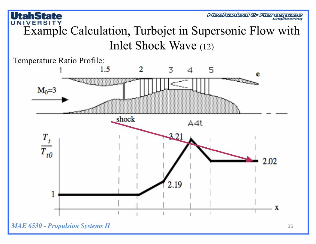
• Summary of results
Pressure Ratios:
Temperature Ratios:
Example Calculation, Turbojet in Supersonic Flow with Inlet Shock Wave (10)
P02
P0∞
= πd = 0.76; P03
P0∞
= πd ⋅πc =11.8
P04
P0∞
= πd ⋅πc ⋅πc =11.8; P05
P0∞
= πd ⋅πc ⋅πc ⋅πt = 2.34
T02
T0∞
= τd =1; T03
T0∞
= τd ⋅τc = 2.19
T04
T0∞
= τd ⋅τc ⋅τc = 3.21; T05
T0∞
= τd ⋅τc ⋅τc ⋅τt = 2.02

MAE 6530 - Propulsion Systems II
• Also
Example Calculation, Turbojet in Supersonic Flow with Inlet Shock Wave (11)
34
P0exitp∞=P05P0∞⋅P0∞p∞=P05P0∞⋅ 1+ γ−1
2M∞
2⎛
⎝⎜⎜⎜
⎞
⎠⎟⎟⎟⎟=
T0exitT∞=T05T0∞⋅T0∞T∞=T05T0∞⋅ 1+ γ−1
2M∞
2⎛
⎝⎜⎜⎜
⎞
⎠⎟⎟⎟⎟=

MAE 6530 - Propulsion Systems II
Pressure Ratio Profile:
Example Calculation, Turbojet in Supersonic Flow with Inlet Shock Wave (11)
35
P0P0∞
MAE 6530 - Propulsion Systems II
Temperature Ratio Profile:
Example Calculation, Turbojet in Supersonic Flow with Inlet Shock Wave (12)
36
P0P0∞

MAE 6530 - Propulsion Systems II
• Recall that this analysis assumes a sonic nozzle
• How would an Expanded (Supersonic) Nozzle Buy in Terms of Performance
• Find the Optimal Expansion Ratio and Exit Mach Number
• By What ratio does this Optimal expansion ratio Increase the thrust and specific Impulse of the Engine
Homework 5.2
37
Mexit > 1

MAE 6530 - Propulsion Systems II
• Hints:
Homework 5.2 (2)
38
Mexit > 1
Fthrustp∞ ⋅ A∞
=Fthrustp∞ ⋅ A∞
= γ ⋅M∞2 ⋅VexitV∞−1
⎛
⎝⎜⎜⎜⎜
⎞
⎠⎟⎟⎟⎟⎟+AexitA∞⋅pexitp∞−1
⎛
⎝⎜⎜⎜⎜
⎞
⎠⎟⎟⎟⎟⎟= γ ⋅M∞
2 ⋅Mexit
M∞
TexitT∞−1
⎛
⎝
⎜⎜⎜⎜⎜
⎞
⎠
⎟⎟⎟⎟⎟⎟+AexitA∞⋅pexitp∞−1
⎛
⎝⎜⎜⎜⎜
⎞
⎠⎟⎟⎟⎟⎟
TexitT0exit=
1
1+ γ−12Mexit
2⎛
⎝⎜⎜⎜
⎞
⎠⎟⎟⎟⎟
TexitT0exit=
1
1+ γ−12Mexit
2⎛
⎝⎜⎜⎜
⎞
⎠⎟⎟⎟⎟
γγ−1
AexitAthroat* =
1Mexit
⋅2γ−1⎛
⎝⎜⎜⎜
⎞
⎠⎟⎟⎟⎟⋅ 1+
γ−12Mexit
2⎛
⎝⎜⎜⎜
⎞
⎠⎟⎟⎟⎟
⎡
⎣⎢⎢
⎤
⎦⎥⎥
γ+12⋅ γ−1( )
• Making these substitutions the normalized thrust can be written in terms of exit Mach number
• Graph Normalized Thrust and Exit expansion ratio as a function of exit Mach Number
• Verify that pexit/p∞ = 1 at the optimal performance condition?
TexitT∞=T0exit
T∞
TexitT0exit
pexitp∞=P0exit
p∞
pexitP0exit
MAE 6530 - Propulsion Systems II 39
Questions??