Embed Size (px)
Citation preview

PASCO scientific Student Manual 53
Section 5
HOW DO WIRES DISTRIBUTE ELECTRIC PRESSURE IN A CIRCUIT?
INTRODUCTION The uniform pressure in a wire is represented by a uniform color. We learned in Section 4 how to assign colors to wires with one end touching a battery terminal or a capacitor plate. But what determines the pressure in a wire that does not touch a battery or a capacitor? INVESTIGATION ONE: HOW DO PRESSURE CHANGES GET TO THE WIRES? 5.1 Activity: Four identical bulbs in series Set up the circuit shown in Figure 5.1. Be sure to use four D-cells – not three. 1. Describe what you observe.
Figure 5.1
FOUR BULBS IN SERIES 2. Draw starbursts on the bulbs in Figure 5.1 to show the brightness of all bulbs. Draw arrowtails nearby to show the flow rates causing the observed brightness. Color code the wires to show the pressure differences that cause the flow rates. 3. Explain why you colored the wires in Figure 5.1 the way you did.
R R
R R
R R
R R

PASCO scientific Student Manual 54
5.2 Activity: What causes pressure change in the wires? In Figure 5.1, all wires had YELLOW (normal) pressure before they were connected in the circuit. The pressure in two of the wires changed to RED and BLUE because they were connected to the (+) and (–) battery terminals. But the colors of the wires that don’t touch the battery can’t be explained so easily. These colors show • above-normal pressure in the top right wire • below-normal pressure in the bottom right wire To make the pressure go above YELLOW in the top right wire and below YELLOW in the bottom right wire, charge must have been compressed in the first wire and depleted in the second. How did that compression and depletion happen? The process occurred too quickly to give us any observable clues. We will slow the process down by adding a lot more metal to the top right and bottom right wires – using capacitor plates, as in Figure 5.2. A lot more charge will have to be compressed and depleted in these plates, in order to cause higher and lower pressure in the top right and bottom right wires. That will require a lot more time.
Figure 5.2 CAPACITOR ADDED ACROSS 2 BULBS AT RIGHT
1. Set up the circuit in Figure 5.2 using a 25,000 µf capacitor. Make the last connection at one of the battery terminals. Describe what you observe. Repeat with a 100,000 µf capacitor, if one is available, to stretch out the time even more. Note that there’s a transient process going on initially, until a steady state is reached. 2. Draw starbursts on the bulbs in Figure 5.2 that show the brightness of each bulb at the instant of connection. Draw arrowtails that show the directions and rates of flow that are causing the observed brightness. Color code the wires to provide a picture of the pressure differences that cause these flows at the first instant of connection.
R
Top capacitor plate adds much more metal to the top right wire Bottom capacitor plate adds much more metal to the lower right wire
R
R
R
R

PASCO scientific Student Manual 55
3. At the instant of connection: a) Is there any movement through the wire between the two bulbs at the right? b) Where is the charge that’s passing through the top bulb going
to? c) Where is the charge passing through the bottom bulb coming from? d) Is charge also passing through the battery? 4. As the charge moves through the glowing bulbs, what pressure changes are caused in the circuit? Explain your reasoning. 5.3 Activity: What happens if the capacitor is not there? 1. The circuit is described as “steady state” when the bulbs’ brightness no longer changes. Show the final condition of the circuit on Figure 5.3a below by drawing starbursts, arrowtails, wire colors and (if appropriate) +/– symbols on the capacitor plates. Now take the capacitor away, without breaking the circuit through the bulbs. 2. Show the circuit’s final condition without a capacitor by drawing all appropriate symbols and colors again on Figure 5.3b.
Figure 5.3a Figure 5.3b
STEADY STATE CIRCUIT STEADY STATE WITH CAPACITOR REMOVED
RR
R
R
R
R
R
R
R

PASCO scientific Student Manual 56
3. Did you observe a change of bulb brightness when you removed the capacitor? Why do you think this was the case? 4 In Activity 5.1, the four-bulb circuit was connected without a capacitor. Was the final steady state any different from the circuit in Figure 5.3b? 5. How do you think the four-bulb circuit gets to its final steady state without a capacitor? 5.4 Commentary: Transient process and steady state in a series circuit A circuit that maintains steady flow rates has the same flow rate through all bulbs (or other resistors) that are connected in series.
But – use your imagination. Consider what would happen in a wire connecting two bulbs if different flow rates through these bulbs were to exist. Remember that the wire is already full of charge before any of the following happens. 1) More charge would be going into the wire through Bulb A
than is coming out of the wire through the Bulb B. 2) This imbalance would cause compression of the charge in the
wire, and would lead to a higher pressure in the wire. 3) The consequences of this pressure increase are very
substantial: • falling pressure difference across the inflow Bulb A makes
inflow rate smaller • rising pressure difference across the outflow Bulb B makes
outflow rate larger • flow rates through the bulbs would become more and more
equal over time Figure 5.4 CONSIDER ONE WIRE BETWEEN TWO BULBS
The process that changes pressure in the wires eventually produces the same flow rate through every bulb connected in series. The flow rates through the series bulbs and the pressure values in the connecting wires will then remain steady. Describing the behavior of the process over time:
• It is transient – changing flow rates result from changing electric pressures.
• It is super-fast in ordinary circuits – because the wires contain very little metal where charges can accumulate; therefore the steady state is reached quickly.
• It can be observed – by adding a capacitor that has a lot more metal in its plates and therefore the transient process takes longer.
R
R
R
R
A
B
Consider this wire

PASCO scientific Student Manual 57
INVESTIGATION TWO: CAN SERIES PRESSURE DIFFERENCES BE UNEQUAL? 5.5 Activity: Non-identical bulbs in series Set up the circuit in Figure 5.5. Connect and disconnect the circuit 5 times – with the compass placed under a different wire each time. (Tape the compass in place and rotate the circuit over it.) 1. Write down what you observe about bulb brightness and compass deflection for the various parts of the circuit. 2. What do you think is happening in the round bulbs?
Figure 5.5 2 KINDS OF BULBS IN SERIES
WITH FOUR CELLS 3. Is there the same flow rate through all the bulbs? How do you know? 4. Is there the same pressure difference across all bulbs? How do you know? 5. Draw arrowtails by the bulbs, which show direction and magnitude for flow rates driven by the pressure differences. Draw starbursts on the bulbs to represent the brightness.
R
R
L
L

PASCO scientific Student Manual 58
5.6 Commentary: Comparing currents in unlike bulbs The flow rate through a bulb is determined by the pressure difference, which drives the flow. But the flow rate through a bulb is also determined by the bulb’s resistance, which hinders movement through the bulb. The driving and hindering factors must be coordinated whenever you want to compare flow rates through unlike bulbs. These two factors are coordinated visually by the arrows of different widths in Table 5.6. The columns indicate that the current through either kind of bulb decreases as the pressure difference across the bulb decreases. The rows indicate that, for the same pressure difference, a low resistance round bulb always allows a greater flow rate to pass through it than a high resistance long bulb does. The table is especially useful for cases where a long bulb and round bulb have equal currents passing through them. Study Table 5.6 to determine what circumstances must exist in order for a round bulb and a long bulb to have exactly the same flow rate.
TABLE 5.6
Table 5.6 shows that there must be more pressure difference across the long bulb than across the round bulb in order for the flow rates to be equal, because it is easier to push charge through a round bulb. For example, a long bulb with a large pressure difference across it should have only about the same current through it as a round bulb with a medium pressure difference. Or a long bulb with a medium pressure difference across it should have only about the same current through it as a round bulb with a small pressure difference.
PressureDifference
Current ThroughRound Bulb
Current ThroughLong Bulb
Large
Medium
Small

PASCO scientific Student Manual 59
5.7 Activity: How did the top and bottom right wires get their pressures? Set up the circuit in Figure 5.7a using a 25,000 µf capacitor and 4 cells in the battery pack. Make the last connection at one of the battery terminals. Notice the difference between this circuit and Figure 5.2. 1. Predict what you will observe when you complete this circuit: Prediction:
Figure 5.7a 2. Describe what you observe. CAPACITOR ADDED
ACROSS THE LONG BULBS
3. Draw starbursts on the bulbs in Figure 5.7a that show the brightness of each bulb at the instant of connection. Draw arrowtails that show the directions and rates of flow everywhere in the circuit at the instant of connection. Color code the wires to provide a picture of the pressure differences that cause these flow rates. 4. As the charge moves through the glowing bulbs, what pressure changes are caused in the circuit? Explain your reasoning. 5. Observe the steady state condition and use the evidence to color code Figure 5.7b. 6. Remove the capacitor from the circuit; do you observe any change of bulb brightness? Explain why this is the case.
Figure 5.7b STEADY STATE
R
R
L
L
R
R
L
L

PASCO scientific Student Manual 60
5.8 Commentary: Series voltage division Bulbs in series share the total pressure difference provided by the battery. But the previous activity shows they don’t share it equally when they don’t have equal resistance values. We have just seen that
• series bulbs with more resistance (long bulbs) have a greater pressure difference
• series bulbs with less resistance (round bulbs) have less pressure difference We may draw a general conclusion for a circuit with resistors in series which has reached a steady-state condition: There is more pressure difference across a larger resistance and less pressure difference across a smaller resistance. Scientists and engineers call this the principle of “series voltage division”. 5.9 Exercise: Two non-identical bulbs in series
Figure 5.9a Figure 5.9b
LONG AND ROUND BULBS IN SERIES 1. Color code the wires in Figures 5.9a and 5.9b. Draw arrowtails to show the flow rates driven by the pressure differences. 2. Explain the reasoning behind your color coding decisions. 3. Draw starbursts to indicate your predictions for bulb brightness. Then construct the circuit to check your work.
R
L
L
R

PASCO scientific Student Manual 61
INVESTIGATION THREE: HOW DO PARALLEL PATHS AFFECT A CIRCUIT? 5.10 Activity: Parallel pair in a series circuit Set up the 3-bulb circuit in Figure 5.10a, with a gap for a fourth bulb to be added. Then add the fourth bulb to form the circuit in Figure 5.10b. To switch back and forth easily between Figures 5.10 a and b, you can add the fourth bulb and its socket, and simply lift the bulb to break the connection for the circuit in Figure 5.10a.
Figure 5.10a Figure 5.10b 2 BULBS IN SERIES WITH A PARALLEL PAIR
1. Write down what you observe about bulb brightness before and after you add in the 4th bulb to form a parallel pair at the right. 2. What do your observations indicate about flow rate through the top and bottom bulbs before and after you add the 4th bulb to form a parallel pair at the right? 3. What does this indicate about the overall resistance of the circuit after a bulb is added in parallel with an original bulb, compared to the overall resistance before? 4. What do your observations indicate about pressure difference across the parallel pair, in comparison with pressure difference across the top or bottom bulb? 5. What does this indicate about the overall resistance of the parallel pair of bulbs, compared to the resistance of an individual bulb?
R
R
R
R
R
R R

PASCO scientific Student Manual 62
5.11 Commentary: Parallel resistance reduction The previous activity shows that a parallel pair has less resistance than a single bulb. We will give the name “parallel resistance reduction” to this property of a parallel combination of resistors. You may wonder: How can two bulbs possibly have less resistance than one bulb? The way out of this puzzle is to note that:
• Parallel resistors provide more paths from a HIGH to a LOW pressure region. The flow rate in an individual path is not reduced by resistance in other paths.
• So a given pressure difference will drive a greater net flow rate from the HIGH
pressure region to the LOW pressure region than it does through a single path. We need a definition of RESISTANCE that takes into account the letting-through effect of parallel paths as well as the holding-back effect of the individual resistors. From now on we will redefine resistance in terms of flow-permitting behavior:
“Less resistance” lets the same pressure difference drive a greater flow rate.
– OR – “Less resistance” lets the same flow rate be driven by less pressure difference.
Our work in the previous activity produced two applications of these statements:
• The four-bulb circuit with a parallel pair has less resistance than the original three-bulb circuit because it lets the same pressure difference drive a greater flow rate through the circuit.
• The parallel pair has less resistance than either of the 2 single bulbs in series because
it lets the same flow rate be driven through even though there is less pressure difference across the pair than there is across either series bulb.
PASCO scientific Student Manual 63
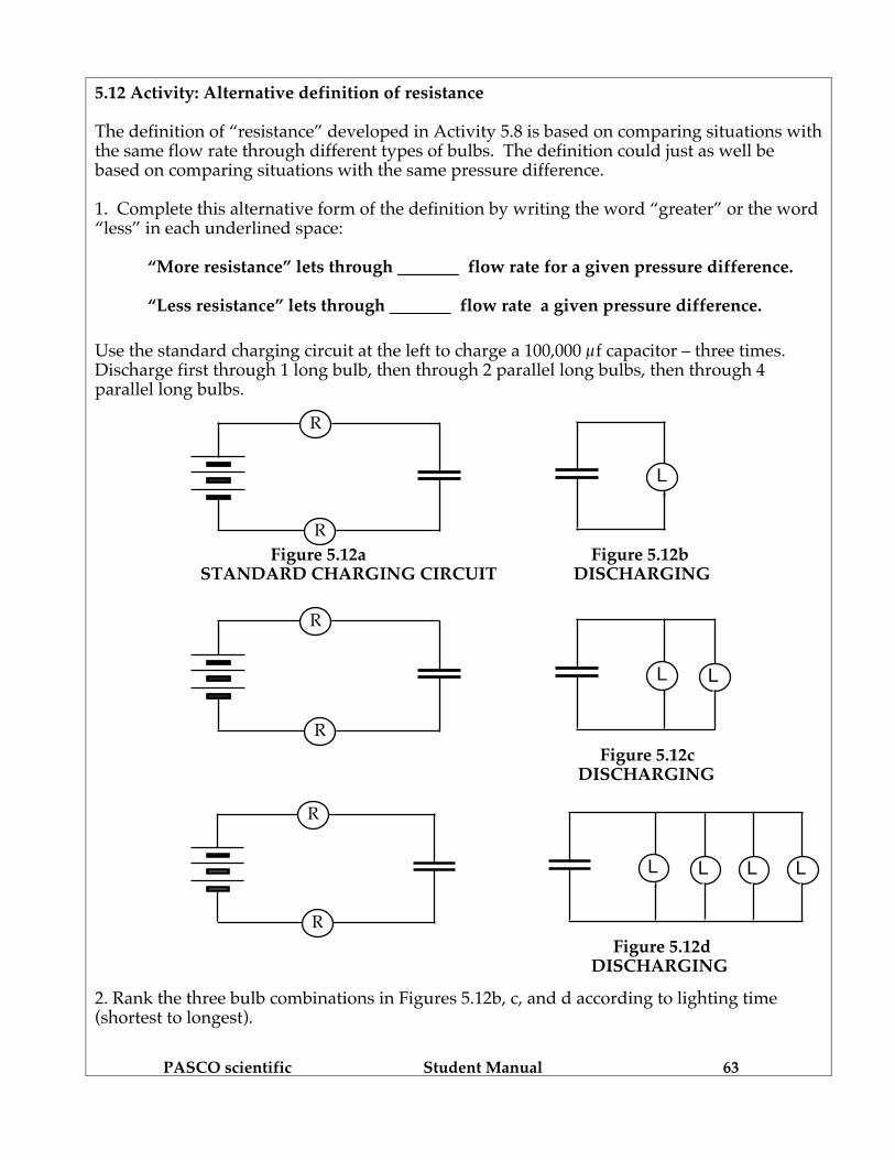
5.12 Activity: Alternative definition of resistance The definition of “resistance” developed in Activity 5.8 is based on comparing situations with the same flow rate through different types of bulbs. The definition could just as well be based on comparing situations with the same pressure difference. 1. Complete this alternative form of the definition by writing the word “greater” or the word “less” in each underlined space:
“More resistance” lets through flow rate for a given pressure difference.
“Less resistance” lets through flow rate a given pressure difference.
Use the standard charging circuit at the left to charge a 100,000 µf capacitor – three times. Discharge first through 1 long bulb, then through 2 parallel long bulbs, then through 4 parallel long bulbs.
Figure 5.12a Figure 5.12b STANDARD CHARGING CIRCUIT DISCHARGING
Figure 5.12c DISCHARGING
Figure 5.12d DISCHARGING 2. Rank the three bulb combinations in Figures 5.12b, c, and d according to lighting time (shortest to longest).
R
R
L
R
R
LL
R
R
LL L L

PASCO scientific Student Manual 64
3. Based on lighting time, rank these bulb combinations according to flow rate. 4. Rank these bulb combinations according to resistance, based on flow rate.
5.13 Activity: Shorting wires and short circuits
Set up a circuit with a round and a long bulb in series, as in Figure 5.13a. Observe carefully as you make three modifications: First connect a long bulb in parallel with the long bulb, then a round bulb, and then just a wire in parallel with the original long bulb as shown in 5.13b, c, and d below. In each case, add the parallel wire by tapping it into the circuit (touch a segment of a bulb socket). Particularly in 5.13d, the round bulb will become stressed – so tap briefly to make your observations.
Figure 5.13a
Figure 5.13b Figure 5.13c Figure 5.13d 1. Color code each of the circuits. Draw arrowtails to indicate flow directions and rates through each bulb as determined with a compass.
2. How does the brightness of the top round bulb change during the progression of parallel branches? Explain why this happens. The wire across the long bulb in Figure 5.13d is called a "shorting wire," a "short circuit," or just a "short." Since this wire cannot sustain a pressure difference, it causes both sides of the long bulb to have blue pressure. The pressure difference across the bulb is therefore zero, and all of the flow must go through the wire.
R
L L
R
L
R
L R
R
L

PASCO scientific Student Manual 65
5.14 Commentary: How does adding branches lower resistance? It seems to defy common sense that adding more resistors to part of a circuit can make less equivalent resistance. But that’s exactly what happens when resistors are added in parallel. Thinking about steady-state flow in the circuit of three identical bulbs shown in Figure 5.14 can help make sense of this idea. You’ll need to keep a couple of things in mind about steady-state flow:
1) Each wire in the circuit is filled with mobile charge, and all of this charge is being driven forward by differences of pressure in the wires.
2) Different pressures were established by compression and depletion in the wires, during
a brief transient stage at the instant of connection. You can visualize the flow pattern by thinking of a moving collection of “little bits.” Figure 5.14 shows four bits (small black circles) entering the single series bulb at the top, at the same time that four other bits are entering the parallel pair at the bottom. Note that the pressure differences are pushing only two bits through each bulb in the parallel pair, while pushing all four bits through the single series bulb. So charge is moving at only half the rate through each parallel bulb as through the single series bulb. How much pressure difference is required to drive a stream of charge at half the rate through one bulb as through another identical bulb? The answer is:
Only half as much pressure difference is needed!
Figure 5.14 STEADY-STATE FLOW WITH ENLARGED VIEW
Enlarged

PASCO scientific Student Manual 66
What does it seem like is happening when you take one resistor, put another one in parallel with it, and discover that you need only half as much pressure difference to push the same flow rate through the pair?
It seems like the original resistance is cut in half! Another way of saying this is that two parallel resistors have the same effect on charge flow as a single resistor with half as much resistance. 5.15 Activity: Non-identical bulbs connected in parallel The ideas we have been developing will now be used to analyze the circuit in Figure 5.15. You will find it useful to connect the two round bulbs in series first, and then to observe how the brightness of the top round bulb A changes when the long bulb C is added in parallel with the bottom round bulb B.
Figure 5.15 PARALLEL COMBINATION CIRCUIT
1. Does the parallel combination behave as if it has a greater or a smaller equivalent resistance than a single round bulb? How do you know? 2. Use the enlarged circuit at the right in Figure 5.15 to diagram the path of charges as they move through the parallel branches. Explain your reasoning. 3. Use a compass to check your answer. What do you observe?
R
R L
R
L R
A
B C

PASCO scientific Student Manual 67
4. Which has the greater pressure difference across it – round bulb A or the two bulbs in parallel? Explain. 5. Color code the circuit. INVESTIGATION FOUR: WHAT FACTORS INFLUENCE BATTERY VOLTAGE? A battery influences pressure differences in flow paths connected to it. Can flow paths influence the pressure difference (“voltage”) in the terminals of a battery? 5.16 Activity: Do flow paths influence pressure difference in battery terminals? Connect a long bulb to the terminals of a 2- cell battery. Place the bulb on the left of the battery, as shown in Figure 5.16a. Be sure to use two cells only! As other conducting paths are added on the right of the battery, as shown in Figures 5.16b and 5.16c, observe what happens to the brightness of the bulb on the left. If the brightness changes, flow through the added path has influenced the pressure difference in the battery terminals. If the brightness stays the same, that flow through the added path had no effect on the pressure difference in the terminals. Add an extra flow path at the right of the cell as in Figure 5.16b and observe the long bulb. Next add a different flow path as in Figure 5.16c by briefly tapping the wire to one of the battery terminals. Circuit 5.16b uses a high resistance bulb to obtain a very small flow rate in the extra path, while circuit 5.16c uses a simple wire with essentially no resistance to obtain the largest possible flow rate.
Figure 5.16a Figure 5.16b Figure 5.16c INITIAL CIRCUIT ADDED LONG BULB TAP WIRE BRIEFLY!
1. What happened to the brightness of the bulb on the left when you added an extra flow path to form circuit 5.16b? What happened to the brightness of this bulb when you added a different extra flow path to form circuit 5.16c?
L L L L

PASCO scientific Student Manual 68
2. Draw starbursts on the three circuit diagrams (Figures 5.16a, b, and c) to show bulb brightness, and draw arrowtails to show flow rates through the battery and through all flow paths. 3. What happened to the pressure difference in the battery terminals when you added the extra flow path in circuit 5.16b? What happened when you added the extra path in circuit 5.16c? What is the evidence? People familiar with electric circuits will say that the added wire in circuit 5.16c is a “shorting wire”, which “short circuits” the battery (reduces its voltage to zero). 5.17 Commentary: Flow paths influence pressure difference in battery terminals Circuit 5.16c demonstrates that a shorting wire can reduce the pressure difference across the battery terminals to zero. This drastic reduction of pressure difference is presumably a consequence of a wire with no resistance allowing charge to flow rapidly out of a battery’s HIGH pressure terminal and into its LOW pressure terminal. Can flow through the non-zero resistance of a bulb filament also influence the pressure difference in the battery terminals? The answer is YES. Consider the cell diagram in Figure 5.17a:
• The shaded interior region represents compounds inside the cell that (a) contain mobile charge and (b) try to push this charge upward.
• The black regions represent High and Low pressure terminals where a pressure
difference due to compression and depletion tries to push the same charge downward.
Figure 5.17a PUSHES IN OPPOSITE DIRECTIONS CANCEL OUT IN
A CELL WHERE THERE IS CHARGE BUT NO FLOW
HIGH
LOW - - - -
++ ++
. . . . . . . . . . . . . . Upward pushing
by chemical action
Downward pushing by pressure difference

PASCO scientific Student Manual 69
When a cell is not connected in a circuit, there is no flow through it. The upward and downward pushes have equal magnitude and cancel each other out.
This picture changes, however, when a cell is connected to a flow path. Activity 5.16 showed that charge flow in a wire connecting the battery terminals can reduce the pressure difference in the terminals. Study the diagrams below (Figure 5.17b, c, and d).
Figure 5.17b Figure 5.17c Figure 5.17d AT THE MOMENT JUST A LITTLE NO MORE CHANGES OF CONNECTION WHILE LATER AFTER A LONG TIME
Figure 5.17b: Pressure difference in the cell terminals starts driving HIGH-to-LOW flow through the bulb at the instant of connection. Figure 5.17c: Flow through the bulb reduces pressure difference in the terminals, and weakens downward pushing by pressure difference in the battery terminals. This allows chemical action to start driving charge upward through the cell.
Figure 5.17d: Falling pressure difference in the battery terminals drives falling flow rate through the bulb and lets chemical action drive growing flow rate through the cell. The two flow rates eventually become equal, and result in:
• steady reduced pressure difference in the battery terminals • same steady flow rate everywhere in the circuit • steady bulb brightness
These bulb lighting changes ordinarily happen so quickly they cannot be observed.
Red
Blue - - - - - -
+++ +++ Red/Orange
Blue/Green
++ ++
- - - -
Orange
Green
+ +
- -

PASCO scientific Student Manual 70
L L R
5.18 Activity: How does battery voltage depend on resistance in the flow path? In Activity 5.16, we found that connecting a flow path to the battery terminals that has practically no resistance (just a wire) will reduce the pressure difference across the terminals all the way down to zero. This activity is a repeat of Activity 5.16 using a round bulb to give the added flow path a resistance that is intermediate between a long bulb and a wire. Set up the circuit in Figure 5.18a, and then connect an extra flow path with a round bulb as indicated in Figure 5.18b. Note: Use a 2-cell battery!
Figure 5.18a Figure 5.18b
STANDARD ADD NEW FLOW PATH CIRCUIT WITH A ROUND BULB
1. What happened to the brightness of the long bulb when a single round bulb was added? Compare this with what happened with a long bulb in the added path (Activity 5.16b). 2. Predict what would happen if you were to repeat the experiment using a group of 3 parallel bulbs as indicated in Figure 5.18c, instead of using a single round bulb.
Prediction:
Figure 5.18c
EXTRA PATH WITH THREE PARALLEL ROUND BULBS
What do you think would happen if you used a group of seven parallel bulbs, as indicated in Figure 5.18d? Prediction:
Figure 5.18d EXTRA PATH WITH SEVEN PARALLEL ROUND BULBS
L R R R
L R R R R R R R

PASCO scientific Student Manual 71
Construct the circuit in Figure 5.18c to test your predictions. (If you choose to construct 5.18d, you will need to borrow sockets from another lab group.) 3. What happened to the pressure difference in the battery terminals when one round bulb was used? When 3 parallel round bulbs were used? When 7 parallel round bulbs were used? What is the evidence? 4. Describe in words the relationship of (a) pressure difference a battery maintains in its terminals to (b) resistance in a flow path connected to the terminals. 5.19 Activity: Does the internal resistance of the battery also have an effect? An experiment in Section 3.14 showed that there is internal resistance in batteries. Recall that when a battery is connected in a circuit, the chemical reactions that drive charge flow are changing its compounds into new compounds that have greater resistance. Your teacher will give you 2 cells that are “run down” due to long use, and have substantially more resistance than the relatively fresh cells you have been using. Use these 2 cells to do the experiments indicated in Figures 5.19a, 5.19b, and 5.19c. Then repeat the experiments using your fresh cells.
Figure 5.19a Figure 5.19b Figure 5.19c FIRST, 3 CIRCUITS WITH OLD CELLS; REPEAT WITH FRESH CELLS 1. What do you observe when you use the high resistance “run down” cells? 2. Compare this with what happens when you use the low resistance fresh cells.
L L L L R

PASCO scientific Student Manual 72
5.20 Commentary: Including the complete battery model in a circuit diagram Our model of a battery now includes two properties: 1) CHEMICAL ACTIVITY – tries to drive charge through a battery. This effort is represented on circuit diagrams by the symbol 2) INTERNAL RESISTANCE – hinders movement through the battery. This is represented on circuit diagrams by the resistance symbol If internal resistance did not exist, a cell could be represented on a diagram by the symbol for property (1) alone –– just as we have been doing until now. We may continue to do this in situations where the resistance in the flow path is so large (R>>r) that property (2) does not have an appreciable effect on the battery voltage. Figures 5.20a, 5.20b, and 5.20c show how to include property (2) in circuit diagrams when the external resistance is not so large. Since chemical activity maintains red-to-blue pressure difference in battery terminals when there is no flow, the symbol for chemical activity should be colored red-to-blue in situations where flow does occur. When there is no flow through the battery, the terminals should also be colored red and blue. In a circuit where flow is occurring, however, there should be a less-HIGH color in the (+) terminal and a less-LOW color in (–) terminal.
BlueRed
terminal
terminal
Red
Blue
BlueRed
Orange
Green
Orange
Green
BlueRed
Yellow Yellow
YellowYellow Figure 5.20 a Figure 5.20b Figure 5.20
ISOLATED CELL IN CIRCUIT WITH FLOW SHORT CIRCUITED

PASCO scientific Student Manual 73
SUMMARY EXERCISE 1. A circuit containing three identical bulbs in series will have equal flow rates through all bulbs when the steady state is reached. Will it have equal flow rates through each bulb in the transient stage at the instant the connection is made? Explain. 2. A single long bulb is connected to a fresh battery. Indicate what will occur when a second long bulb is added in parallel to the first bulb.
Select from: Increase Decrease Little or No Change (A) the electric pressure difference across the battery terminals ________ (B) the electric pressure difference across the first bulb ________ (C) the flow rate of charge through the battery ________ (D) the flow rate of charge through the first bulb ________ 3. Is the net resistance (or total resistance) of a series combination more than the resistance of any single bulb in the combination? Why or why not? 4.. Is the net resistance of a parallel combination more than the resistance of any single resistor in the combination? Why or why not?

PASCO scientific Student Manual 74
5. How does the flow rate of charge in a parallel circuit divide – a) if all branches of the circuit have the same resistance? b) if different branches have different resistance values? 6. Does Choice A or Choice B provide the best representation of the transient process that occurs after the circuit is closed? Explain your reasoning.
First Instant Choice A Choice B Steady State of Closure
7. A simple circuit contains a battery and a single light bulb. What effect does adding a wire in parallel with the light bulb have on – (A) the electric pressure difference across the bulb? (B) the flow rate of charge through the bulb? (C) the pressure difference across the battery terminals?
Choose One
R
L
R R R
L L L