Embed Size (px)
Citation preview

Section 4. Underground Service
ElEctrical SErvicE rEquirEmEntSPage 4 - 1New: 10/90 Revised: 03/30/2015
Table of ConTenTs
Section 4Underground Service
A. GENERAL .......................................................................................................................... 4-7B. PRIMARY SERVICE - RESIDENTIAL SYSTEMS ON PRIVATE PROPERTY ............ 4-7C PRIMARY SERVICE - COMMERCIAL SYSTEMS ON PRIVATE PROPERTY ........... 4-7D. TRENCHING ..................................................................................................................... 4-8E. CONDUIT AND FITTINGS FOR DISTRICT INSTALLED CONDUCTORS ............. 4-13F. TEMPORARY CONSTRUCTION SERVICE ................................................................. 4-18G. RESIDENTIAL SERVICE EQUIPMENT ....................................................................... 4-19H. METER PEDESTAL - 200 AMP & 400 AMP METER SOCKET .................................. 4-25I. CONVERSIONS, O/H TO U/G ........................................................................................ 4-29J. COMMERCIAL/APARTMENT SECONDARY PEDESTALS ....................................... 4-31K. PADMOUNT TRANSFORMER EQUIPMENT, CLEARANCE .................................... 4-31L. CONNECTION TO PADMOUNT TRANSFORMERS, SECONDARY CABINETS
SECONDARY HANDHOLES OR SECONDARY PEDESTALS .................................. 4-34M. CONCRETE VAULTS, PADS AND HANDHOLES ....................................................... 4-36N. GROUNDING .................................................................................................................. 4-40O. VAULT ROOMS ............................................................................................................... 4-41P. MAINTENANCE ............................................................................................................. 4-42Q. INCREASING CAPACITY - EXISTING VAULT LOCATION...................................... 4-43

Section 4. Underground Service
Page 4 - 2ElEctrical SErvicE rEquirEmEntSNew: 10/90 Revised: 03/30/2015
This Page Intentionally Left Blank
Section 4. Underground Service
ElEctrical SErvicE rEquirEmEntSPage 4 - 3New: 10/90 Revised: 03/30/2015
Tables, forms and IllusTraTIons
Section 4Illustrations And Tables
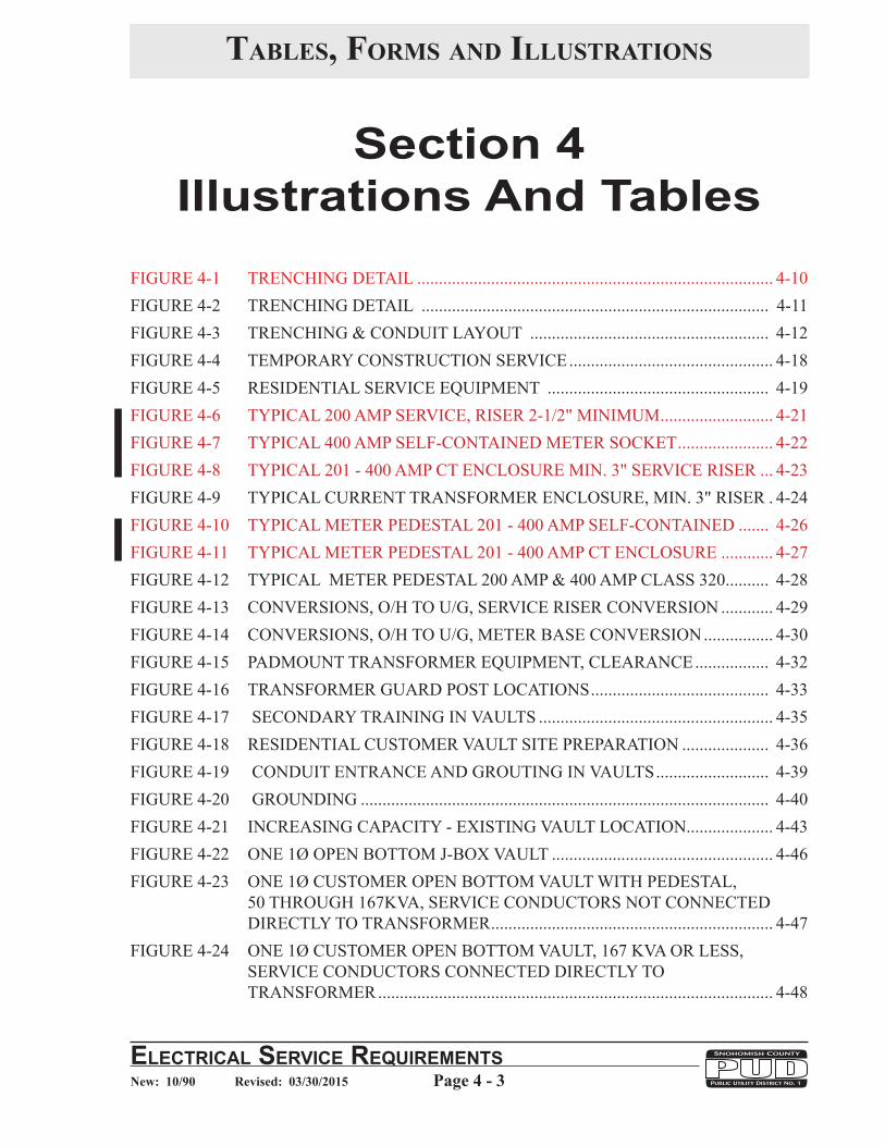
FIGURE 4-1 TRENCHING DETAIL .................................................................................. 4-10FIGURE 4-2 TRENCHING DETAIL ................................................................................ 4-11FIGURE 4-3 TRENCHING & CONDUIT LAYOUT ....................................................... 4-12FIGURE 4-4 TEMPORARY CONSTRUCTION SERVICE ............................................... 4-18FIGURE 4-5 RESIDENTIAL SERVICE EQUIPMENT ................................................... 4-19FIGURE 4-6 TYPICAL 200 AMP SERVICE, RISER 2-1/2" MINIMUM .......................... 4-21FIGURE 4-7 TYPICAL 400 AMP SELF-CONTAINED METER SOCKET ...................... 4-22FIGURE 4-8 TYPICAL 201 - 400 AMP CT ENCLOSURE MIN. 3" SERVICE RISER ... 4-23FIGURE 4-9 TYPICAL CURRENT TRANSFORMER ENCLOSURE, MIN. 3" RISER . 4-24FIGURE 4-10 TYPICAL METER PEDESTAL 201 - 400 AMP SELF-CONTAINED ....... 4-26FIGURE 4-11 TYPICAL METER PEDESTAL 201 - 400 AMP CT ENCLOSURE ............ 4-27FIGURE 4-12 TYPICAL METER PEDESTAL 200 AMP & 400 AMP CLASS 320 .......... 4-28FIGURE 4-13 CONVERSIONS, O/H TO U/G, SERVICE RISER CONVERSION ............ 4-29FIGURE 4-14 CONVERSIONS, O/H TO U/G, METER BASE CONVERSION ................ 4-30FIGURE 4-15 PADMOUNT TRANSFORMER EQUIPMENT, CLEARANCE ................. 4-32FIGURE 4-16 TRANSFORMER GUARD POST LOCATIONS ......................................... 4-33FIGURE 4-17 SECONDARY TRAINING IN VAULTS ...................................................... 4-35FIGURE 4-18 RESIDENTIAL CUSTOMER VAULT SITE PREPARATION .................... 4-36FIGURE 4-19 CONDUIT ENTRANCE AND GROUTING IN VAULTS .......................... 4-39FIGURE 4-20 GROUNDING .............................................................................................. 4-40FIGURE 4-21 INCREASING CAPACITY - EXISTING VAULT LOCATION.................... 4-43FIGURE 4-22 ONE 1Ø OPEN BOTTOM J-BOX VAULT ................................................... 4-46FIGURE 4-23 ONE 1Ø CUSTOMER OPEN BOTTOM VAULT WITH PEDESTAL, ............
50 THROUGH 167KVA, SERVICE CONDUCTORS NOT CONNECTED ........ DIRECTLY TO TRANSFORMER ................................................................. 4-47
FIGURE 4-24 ONE 1Ø CUSTOMER OPEN BOTTOM VAULT, 167 KVA OR LESS, ......... SERVICE CONDUCTORS CONNECTED DIRECTLY TO ................................ TRANSFORMER ........................................................................................... 4-48

Section 4. Underground Service
Page 4 - 4ElEctrical SErvicE rEquirEmEntSNew: 10/90 Revised: 03/30/2015
Tables, forms and IllusTraTIons
Section 4Illustrations And Tables
FIGURE 4-25 ONE OR MORE 1Ø CUSTOMERS, TRANSFORMER VAULT WITH ............. SECONDARY HANDHOLE, 167 KVA OR LESS, SERVICE ............................ CONDUCTORS NOT CONNECTED DIRECTLY TO TRANSFORMER, ......... OPTION 1 ....................................................................................................... 4-49
FIGURE 4-26 ONE OR MORE 1Ø CUSTOMERS, TRANSFORMER VAULT WITH ............. SECONDARY HANDHOLE, 167 KVA OR LESS, SERVICE ............................ CONDUCTORS NOT CONNECTED DIRECTLY TO TRANSFORMER, ......... OPTION 2 ....................................................................................................... 4-49
FIGURE 4-27 ONE 3Ø CUSTOMER TRANSFORMER VAULT, 75-500 KVA, SERVICE ...... CONDUCTORS CONNECTED DIRECTLY TO TRANSFORMER ........... 4-49
FIGURE 4-28 ONE 3Ø CUSTOMER TRANSFORMER VAULT, 75-500 KVA, SERVICE ...... CONDUCTORS CONNECTED DIRECTLY TO TRANSFORMER, ................. CONDUCTORS SIZES 500 KCMIL AND LARGER ................................... 4-50
FIGURE 4-29 ONE OR MORE 3Ø CUSTOMERS, TRANSFORMER VAULT WITH ............. SECONDARY HANDHOLE, 75-500 KVA, SERVICE CONDUCTORS ............ NOT CONNECTED DIRECTLY TO TRANSFORMER .............................. 4-51
FIGURE 4-30 ONE 3Ø CUSTOMER, TRANSFORMER VAULT, 750-2500 KVA, SERVICE . CONDUCTORS CONNECTED DIRECTLY TO TRANSFORMER, ................................... CONDUCTOR SIZES LESS THAN 500 KCMIL. ........................................ 4-52
FIGURE 4-31 ONE OR MORE 3Ø CUSTOMERS, TRANSFORMER VAULT WITH ............. SECONDARY CABINET, 75-500 KVA, SERVICE CONDUCTORS .................. NOT CONNECTED DIRECTLY TO TRANSFORMER .............................. 4-53
FIGURE 4-32 ONE 3Ø CUSTOMER TRANSFORMER VAULT, 750-2500 KVA, ................... SERVICE CONDUCTORS NOT CONNECTED DIRECTLY TO ...................... TRANSFORMER ........................................................................................... 4-54
FIGURE 4-33 ONE OR MORE 3Ø CUSTOMERS, 750-2500 KVA, SERVICE ......................... CONDUCTORS CONNECTED DIRECTLY TO TRANSFORMER, ................. CONDUCTOR SIZES 500 KCMIL AND LARGER. .................................... 4-55
FIGURE 4-34 ONE OR MORE 3Ø CUSTOMERS, TRANSFORMER VAULT WITH ............. SECONDARY CABINET, 75-500 KVA, SERVICE CONDUCTORS NOT ....... CONNECTED DIRECTLY TO TRANSFORMER ....................................... 4-56

Section 4. Underground Service
ElEctrical SErvicE rEquirEmEntSPage 4 - 5New: 10/90 Revised: 03/30/2015
Section 4Illustrations And Tables
FIGURE 4-35 ONE OR MORE 3Ø CUSTOMERS, TRANSFORMER VAULT WITH ............. SECONDARY CABINET, 750-2500 KVA, SERVICE CONDUCTORS ............. NOT CONNECTED DIRECTLY TO TRANSFORMER .............................. 4-57
FIGURE 4-36 20 POSITION TERMINATION CABINET ................................................... 4-58FIGURE 4-37 30 POSITION TERMINATION CABINET ................................................... 4-59
TABLE 1 MINIMUM CONDUIT SIZE ......................................................................... 4-16TABLE 2 1Ø PADMOUNT TRANSFORMER SELECTION GUIDE .......................... 4-44TABLE 3 3Ø PADMOUNT TRANSFORMER SELECTION GUIDE .......................... 4-45
Tables , forms and IllusTraTIons

Section 4. Underground Service
Page 4 - 6ElEctrical SErvicE rEquirEmEntSNew: 10/90 Revised: 03/30/2015
This Page Intentionally Left Blank

Section 4. Underground Service
ElEctrical SErvicE rEquirEmEntSPage 4 - 7New: 10/90 Revised: 03/30/2015
UNDERGROUND SERVICEA. GENERAL
1. All conditions for service application, availability of service, type of service, electrical wiring permit, inspection, right-of-way, easements, etc., are covered in “Section 2, General Requirements.”
2. Availability and location of District facilities for providing underground service shall be determined at the District’s office before proceeding with the wiring. Only one service strike will be allowed per building. Plans, specifications, load data, grades and stakes Form #1373 for all underground services shall be submitted to the District as much in advance as possible prior to any construction.
3. The District will design, install, own and maintain the complete primary underground electric distribution system and all associated secondary distribution in the public right-of-way.
4. Underground service installation requiring a special voltage or more than 30 feet of road boring will require individual consideration for feasibility and charges required.
5. The customer shall notify Utilities Underground Location Center by calling 811 or 1-800-424-5555 not less than two-business days or more than ten business days before the commencement of excavation or trenching to allow for location of existing underground utilities by their representatives (RCW 19.122.030).
B. PRIMARY SERVICE - RESIDENTIAL SYSTEMS ON PRIVATE PROPERTY
1. The customer shall prepare the vault site, provide easements, trenching, conduits, pull ropes, and related equipment on private property.
2. The District will install, own and maintain the vault, grounds, secondary handhole and secondary service conductors.
C. PRIMARY SERVICE - COMMERCIAL SYSTEMS ON PRIVATE PROPERTY
1. The customer shall provide easements, trenching, conduits, pull ropes, vaults, handholes, grounds, secondary service conductors and related equipment on private property.

Section 4. Underground Service
Page 4 - 8ElEctrical SErvicE rEquirEmEntSNew: 10/90 Revised: 03/30/2015
2. Transformer vaults, pulling/switching handholes and other equipment vaults shall be located in accordance with the requirements listed in Section 4-K of this section. Refer also to Section 4 Table 2 & 3 for specifics on various vaults, pads and handholes required for each individual project as determined by the District.
Note: Acceptable precast concrete products are locally available from three companies:
Oldcastle Precast, Inc. CUZ Concrete Products Auburn, WA - phone - 800-892-1538 Arlington, WA - phone - 800-659-1941
Granite Precasting & Concrete, Inc. Bellingham, WA - phone - 800-808-2251
3. Systems on Private Property
The District will design, install, own and maintain the primary underground cable, transformers and switch cabinets as required for distribution systems on private property.
Exception: The District shall not normally provide this service beyond primary metering if the system is customer owned.
D. TRENCHING
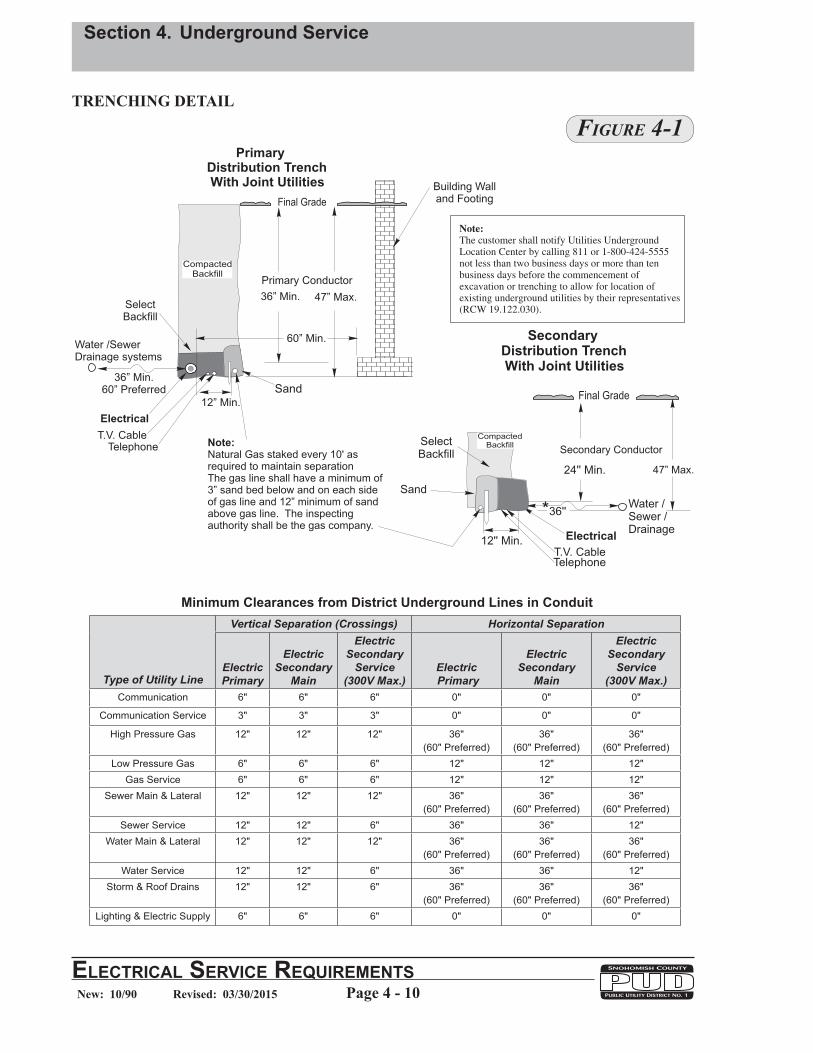
1. For primary and secondary service trenching requirements refer to Figures 4-1 through 4-3.
a. The minimum cover depth for secondary service shall be 24 inches and the maximum trench depth shall be 47 inches.
b. The minimum cover required for primary, 36". The maximum trench depth for secondary or primary conductor shall be 47". Refer to Figure 4-1.
2. All secondary service conductors are to be installed in continuous conduit from the meter base or CT can to the District's point of service.
3. In general, all trenching, backfilling and restoration work on private property shall be done by the customer.
4. Minimum depth requirements may be reduced where unusual soil conditions dictate. Contact the District for specific requirements for these cases.
5. Gas lines shall be staked every 10' as required to maintain separation.
6. For minimum separation between electric lines and other utilities refer to Figure 4-1 on Page 4-10.

Section 4. Underground Service
ElEctrical SErvicE rEquirEmEntSPage 4 - 9New: 10/90 Revised: 03/30/2015
7. The bottom of the trench should be undisturbed, tamped, or relatively smooth earth. Where the excavation is in rock, the conduit should be laid on a protective layer of clean tamped backfill. Backfill within 6" of the electrical conduit should be free of solid material greater than 4" maximum or sharp edges likely to damage it. The balance of backfill should be free of solid material greater than 8" in maximum dimension. All backfill should be free of materials that may damage the conduit system (large rock or paving material, cinders, large or sharply angular substance, or corrosive material). Refer to NESC 321. Sand shall be required if select backfill material is not available. Select backfill or sand shall provide a 3" bedding below the conduit and a minimum cover of 3". Refer to Section 1, page 2, Backfill definition. Backfill material should be adequately compacted.
Note: The District must inspect and approve all conduit installations prior to backfilling.
8. The customer shall trench all the way to the District pedestal or point of service.
9. Within 24 hours after the District's inspection of the ditch and conduit and prior to the District installing the service and meter the customer shall prepare a work area leveled and cleared of all debris and obstructions at the metering point to provide the service conductors to be safely installed by the District. This work area shall be 5 feet x 5 feet minimum centered around the meter base, backfilled and compacted to within 4 inches of final grade.
Section 4. Underground Service
Page 4 - 10ElEctrical SErvicE rEquirEmEntSNew: 10/90 Revised: 03/30/2015
TRENCHING DETAIL
Figure 4-1
SecondaryDistribution TrenchWith Joint Utilities
24'' Min.
T.V. Cable
Electrical
Water /Sewer /Drainage
*36''
Final Grade
Secondary Conductor
47” Max.
Telephone
SelectBackfill
12'' Min.
CompactedBackfill
Sand
Natural Gas staked every 10' asrequired to maintain separation
of3” sand bed below and on each sideof gas line and 12” minimum of sandabove gas line. The inspectingauthority shall be the gas company.
Note:
The gas line shall have a minimum
Telephone
SelectBackfill
Building Walland Footing
12” Min.
T.V. Cable
Electrical
Water /SewerDrainage systems
CompactedBackfill
36” Min.60” Preferred
PrimaryDistribution TrenchWith Joint Utilities
Final Grade
36” Min.
60” Min.
47” Max.
Primary Conductor
Sand
Note:
The customer shall notify Utilities UndergroundLocation Center by calling 811 or 1-800-424-5555not less than two business days or more than tenbusiness days before the commencement ofexcavation or trenching to allow for location ofexisting underground utilities by their representatives(RCW 19.122.030).
Type of Utility Line
Vertical Separation (Crossings) Horizontal Separation
Electric Primary
Electric Secondary
Main
Electric Secondary
Service (300V Max.)
Electric Primary
Electric Secondary
Main
Electric Secondary
Service (300V Max.)
Communication 6" 6" 6" 0" 0" 0"
Communication Service 3" 3" 3" 0" 0" 0"
High Pressure Gas 12" 12" 12" 36" (60" Preferred)
36" (60" Preferred)
36" (60" Preferred)
Low Pressure Gas 6" 6" 6" 12" 12" 12"Gas Service 6" 6" 6" 12" 12" 12"
Sewer Main & Lateral 12" 12" 12" 36" (60" Preferred)
36" (60" Preferred)
36" (60" Preferred)
Sewer Service 12" 12" 6" 36" 36" 12"Water Main & Lateral 12" 12" 12" 36"
(60" Preferred)36"
(60" Preferred)36"
(60" Preferred)Water Service 12" 12" 6" 36" 36" 12"
Storm & Roof Drains 12" 12" 6" 36" (60" Preferred)
36" (60" Preferred)
36" (60" Preferred)
Lighting & Electric Supply 6" 6" 6" 0" 0" 0"
Minimum Clearances from District Underground Lines in Conduit

Section 4. Underground Service
ElEctrical SErvicE rEquirEmEntSPage 4 - 11New: 10/90 Revised: 03/30/2015
TRENCHING & CONDUIT DETAIL
3’
Install 1/4" pull rope.Refer to Section 4.E.
Install a poly duct plug to keepout dirt. Refer to Section 4.E.
Integrally FormedDeep Socket Coupling
Towards Pedestal
Pedestal
Open Trench To Pedestal
Continuous Secondary ConduitRefer to Section 4.E.
P.U.D.
Install poly duct plug to keep
out dirt. Refer to Section 4. .
Install 1/4" pull rope.
Refer to Section 4. .
E
E
Secondary ConduitRefer to Section 4. .E
Select Backfill:
Builders Sand orMaterial WhichWill Pass ThroughA ½” Screen
24'' Min.
Trench
Service Conductor
47’' Max.
Note:
The customer shall notify Utilities UndergroundLocation Center by calling 811 or 1-800-424-5555not less than two business days or more than tenbusiness days before the commencement ofexcavation or trenching to allow for location ofexisting underground utilities by their representatives(RCW 19.122.030).
Figure 4-2

Section 4. Underground Service
Page 4 - 12ElEctrical SErvicE rEquirEmEntSNew: 10/90 Revised: 03/30/2015
TRENCHING & CONDUIT LAYOUT
Figure 4-3
Install 1/4" pull rope.Refer to Section 4.E.
Install a poly duct plug to keepout dirt. Refer to Section 4.E.
24'’ Min.Minimum
24'' radius 90°
Integrally FormedDeep Socket Coupling
Towards Pedestal
Continuous conduit to pedestal locationRefer to Section 4.E.
No conduit coupling allowed onconduit riser above grade.
Refer to Section 4.E.
47’' Max.
House 1 House 2
PL
PL
PL
4’
1’
3’W
orkPit
12”
2’
PVC TO STOP 3’ SHORT OFTHE PEDESTAL.2’ X 4’ WORK PIT TO BE DUGOUT BY CUSTOMER,LEAVING 1’ OF PVCEXPOSED.MUST BE 1’ OF SEPARATIONBETWEEN ELECTRICALCONDUIT PVC’S.
Note:
The customer shall notify Utilities UndergroundLocation Center by calling 811 or 1-800-424-5555not less than two business days or more than tenbusiness days before the commencement ofexcavation or trenching to allow for location ofexisting underground utilities by their representatives(RCW 19.122.030).
ELE
CT
RIC

Section 4. Underground Service
ElEctrical SErvicE rEquirEmEntSPage 4 - 13New: 10/90 Revised: 03/30/2015
E. CONDUIT AND FITTINGS FOR DISTRICT INSTALLED CONDUCTORS
1. All nonmetallic PVC conduit and fittings shall be pigmented gray in color and must be manufactured by a currently approved District manufacturer in addition to meeting the following requirements:
a. The following information shall be imprinted on all PVC conduit:
1. Manufacturer's name or trademark2. Nominal size3. Material (PVC)4. Standard designation (for example, NEMA TC-2)5. Type (for example, Schedule 40)6. Maximum 90° wire, Max. 90°C wire or equivalent phraseology7. Date code or month and year of manufacture
b. 1", 2", 2-1/2" and 3" PVC conduit shall be gray and shall meet or exceed the requirements of the following standards:
1. NEMA TC-2 (Schedule 40 or 80)2. District Material Standard No. 250027.1
c. 4" and 6" PVC shall be gray and shall meet or exceed the requirements of District Material Standard No. 250027.1 and any one of the following standards:
1. NEMA TC-6 DB-602. NEMA TC-8 DB-1203. NEMA TC-2 (Schedule 40 or 80)4. ASTM F-512 DB-60
d. Schedule 40 or 80 gray PVC conduit is required for service riser according to NEC 300-5d. and NEMA Standard TC-2 for applications listed below:
Type III - Designed for normal-duty applications above ground (Sch 40)Type IV - Designed for heavy-duty applications above ground (Sch 80) (Hazardous areas, e.g., next to driveways)
e. Primary conduit bends shall be heavy wall fiberglass or hot-dip galvanized rigid steel electrical conduit.
f. All conduit bends shall be long radius type.
Conduit Diameter Minimum Radius 2", 2-1/2", 3" 24" 4" 48" 6" 60"

Section 4. Underground Service
Page 4 - 14ElEctrical SErvicE rEquirEmEntSNew: 10/90 Revised: 03/30/2015
g. Each PVC conduit joint must be permanently assembled using a PVC solvent cement appropriate for the application.
h. The District accepts smooth-wall coilable polyethylene electrical plastic conduit, also known as high density polyethylene (HDPE) conduit or poly pipe, for directional bore applications only. Poly pipe must meet the following requirements:
1. District Material Standard 250027.2 High Density Polyethylene Conduit2. Trade Size Type Reference Standard 2", 2-1/2", 3" EPEC Schedule 40 NEMA TC 7
4", 6" SDR 13.5 ASTM D 30353. Color The conduit material shall conform to any one of the following three color
alternatives. The order of the District’s preference is a., b. and c. a. Solid black compound which is UV stabilized for outdoor use per
ASTM D 3350 with three continuous red stripes co-extruded longitudinally into the black compound. The red stripes shall be spaced 120° apart. The red color compound shall be compatible with the black compound, and shall also be UV stabilized. The red stripes shall be a minimum of 1/4" wide.
b. Solid red compound UV stabilized for outdoor use per ASTM D 3350.
c. Solid gray compound UV stabilized for outdoor use per ASTM D 3350.
4. Identification The following permanent identification markings (items a. - e.) are required
and shall be provided at intervals of not more than 5 feet. The information may be listed on the conduit in the order preferred by the manufacturer.
a. Manufacturer’s name or trademark b. Trade size (in inches) c. Wall thickness, schedule or dimension ratio (DR) d. Date code or month and year of manufacture
e. HDPE f. NEMA TC 7 (for conduit sizes 2", 2-1/2", 3") and ASTMD D3035
(for conduit sizes 4" and 6") g. Other markings are acceptable if they do not conflict with and
cannot be confused with the required markings. 5. Couplings
The customer shall provide mechanical couplings designed for joining PVC conduit to each end of the poly pipe without the use of adhesive compounds. The customer shall install the couplings on the poly pipe only if directed to do so by the District. The poly pipe ends shall be made round to enable proper installation of couplings.

Section 4. Underground Service
ElEctrical SErvicE rEquirEmEntSPage 4 - 15New: 10/90 Revised: 03/30/2015
2. Secondary Conduit Requirements
a. Continuous conduit from the customer's service entrance to the District's point of service must be used for all underground secondary service cable installations.
b. Schedule 40 PVC shall be used as a minimum.
c. Conduits shall stop 3 feet from the point of service as provided by the District.
d. The formed deep socket coupling (large flared end) of the conduit may be pointed in either direction.
e. A continuous length of knot-free 1/4 inch polypropylene pull rope, or Herculine P1250W 1/2" polyester pull tape, shall be installed by the customer with a 2 foot tail at each end for all secondary conduit(s), including future conduit(s), regardless of length of run.
f. All bends shall be Schedule 40 PVC long radius (Refer to 4.E.1.f.). Factory made bends, including "pronto" type bends are acceptable. PVC conduit shall not be mechanically heated in the field to form any sweep (bend).
g. Conduit couplings (and formed swedge reducers for a 3 inch conduit to a 2-1/2" conduit) are not allowed on an underground service riser above final grade.
h. A bell end shall not be installed on the end of the conduit, however, a tapered manufactured poly conduit plug (no duct tape) shall be installed on all conduit ends to seal exposed ends of conduits, including future conduit(s), to keep out dirt and foreign objects prior to the District installing the conductors. If requested, the District may furnish the customer with the plug(s).
i. The District will extend the conduit into the pedestal or riser pole with a manufactured elbow, rigid, or flex conduit when service is installed.
j. The maximum continuous service conduit run shall be 250 feet in length, from the meter base to the point of service.
k. Secondary conduit shall be allowed a maximum total aggregate of 270° of total bends including the riser. All bends shall be long radius type (24 inch minimum).
l. The conduit size for a 200 amp residential service riser shall be a minimum of 2-1/2 inches for 4/0 - 2/0 triplex.
m. The conduit size for a 201 - 400 amp residential service riser shall be a minimum of 3 inches for 350 kcm - 4/0 triplex.
n. Refer to Table 1 for conduit fill requirements.

Section 4. Underground Service
Page 4 - 16ElEctrical SErvicE rEquirEmEntSNew: 10/90 Revised: 03/30/2015
3. Primary Conduits in Trenches
a. Conduit is required for all primary conductors on private property. All bends shall be long radius fiberglass or rigid steel electrical conduit. A maximum of 180° of bends shall be allowed. Exception: Naturally formed long sweeps of PVC conduit of 1° to 90° will be allowed.
1.) All bends shall be Schedule 40 PVC long radius (Refer to 4.E.1.f.). Factory made bends, including "pronto" type bends are acceptable. PVC conduit shall not be mechanically heated in the field to form any sweep (bend).
2.) Conduit shall not be placed in the trench to form a long sweep prior to the setup of cement in all joints involved. Cement setup time shall be per the manufacturers recommendations.
b. There shall be a 60-inch minimum separation between a primary conduit and a building wall.
Table 1
Minimum Conduit Size Triplex and Quadruplex Secondary Conductors
600V XLP Insulated Conductors Triplex Quadruplex
Phase Neutral One Run Two Runs One Run Two Runs 1/0 2 2-1/2” 3” 3” 3” 4/0 2/0 2-1/2” 3” 3” 4”
350 kcmil 4/0 3” 4” 3” 4” 500 kcmil 250 kcmil 4” 4” 4” 6” 500 kcmil 300 kcmil 4” 4” 4” 6” 500 kcmil 350 kcmil 4” 4” 4” 6” 750 kcmil 400 kcmil 4” 6” 4” 6” 750 kcmil 500 kcmil 4” 6” 4” 6”
1000 kcmil 500 kcmil 4” 6” 4” 6”
Notes: 1. Conduit sizes in Table 1 apply to 2-1/2” and 3” Schedule 40 and 4” and 6” DB-60. 2. Table 1 assumes proper alignment of conduit and proper cable installation where the length
of the pull and the number and size of conduit bends are within reasonable limits. 3. The minimum conduit size for a 200 amp residential service riser shall be 2-1/2” for 4/0-2/0
triplex cable. 4. Five inch conduit is unacceptable as it is not a District standard. Customers must use conduit
sizes compatible with District standards to enable the District to repair or extend customer-installed conduit in the future, if necessary.

Section 4. Underground Service
ElEctrical SErvicE rEquirEmEntSPage 4 - 17New: 10/90 Revised: 03/30/2015
c. Minimum primary conduit sizes shall be 2 inches for single phase and 4 inches for three phase. Larger backbone feeder conduits shall be specified and required on an individual project design basis.
d. The customer shall install a continuous length of knot-free 1/4 inch polypropylene pull rope, or Herculine P1250W 1/2" polyester pull tape, (with a 2 foot tail at each end) and a tapered, manufactured poly conduit plug (no duct tape) at each end for all primary conduit(s), including future conduit(s), regardless of length of run.
4. Under Buildings
The District will only allow powerlines to be installed under a building when it is absolutely unavoidable and is approved by the District Manager or his designee prior to installation.
a. The required conduit(s) shall be paralleled by an equal spare conduit(s) from the pole to the vault or between vaults.
b. Conduits shall not pass through or conflict with the building’s foundation walls.
c. Conduits shall be encased in concrete. Minimum encasement shall be 2 inches thick on all sides of the conduits.
Exception: The concrete encasement requirement can be waived if the building will have a minimum 4 inch thick concrete slab first floor and no basement.
d. A Hold Harmless Clause will be added to and become part of the power line easement.
5. Conduits terminating in a handhole or vault shall have protective bushings on steel conduits. PVC conduit shall extend 5 inches into the vault and be temporarily sealed with a tapered, manufactured poly conduit plug. The District will install all bell ends on PVC conduit entering vaults, for primary conductors.

Section 4. Underground Service
Page 4 - 18ElEctrical SErvicE rEquirEmEntSNew: 10/90 Revised: 03/30/2015
F. TEMPORARY CONSTRUCTION SERVICE
1. The customer shall furnish and install all required equipment.
2. Approved service equipment provided by customer includes support post and bracing, conduit, meter socket, ground rod, conductors, weatherproof disconnect switch and receptacle box.
3. The District Point of Connection shall be at the pedestal or transformer for both residential and commercial temporary installations. The customer shall be responsible for voltage drop between the point of connection and the meter.
4. Temporary post and bracing to be clear of the pedestal and/or transformer with at least a 3 foot minimum distance from the nearest source of power. Refer to Figure 4-4.
5. All temporary installations shall be on private property.
6. The District will not energize service until the installation is approved by the appropriate electrical inspector.
7. The customer shall backfill within 24 hours after District inspection and/or conductors are installed. Sand shall be required if select backfill material is not available. Select backfill or sand shall provide a 3" bedding below conductors and a minimum cover of 3" above conductors. Refer to Section 1, page 2, Backfill definition.
Power
Pedestal
Support Post4'' x 4'' Min.
Meter Socket
Braces & Stakes2'' x 4'' Min.
See Note 1
45° Angletypical
36'' Min.
6' Max.3' Min.
Leave enough wire forconnection in pedestal4' min. 5’ max. from bottomof ditch at pedestal end.
.Do Not Enter Pedestal
Existing Gra
de
Ground rod, wire andclamp provided bycustomer per NEC.
36" Min.
24'' Min.
ELEC
TRIC
Coil or Lay conductor tomaintain a 24” depth orexcess conductor will becut off by the District
Locate ground rod onthe back side of thetemporary post out ofthe workpit and notin the way for workers.
All bracing shall be locatedso that it does not go overthe top of the workpit andout of the way of workers.
Locate temporary oneither side of the pedestal(longest sides). Do Not locatetemporary on front or backside of pedestal (shortest sides).
Figure 4-4
Section 4. Underground Service
ElEctrical SErvicE rEquirEmEntSPage 4 - 19New: 10/90 Revised: 03/30/2015
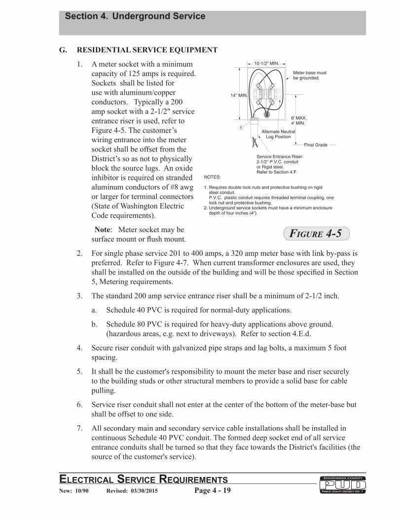
G. RESIDENTIAL SERVICE EQUIPMENT
1. A meter socket with a minimum capacity of 125 amps is required. Sockets shall be listed for use with aluminum/copper conductors. Typically a 200 amp socket with a 2-1/2" service entrance riser is used, refer to Figure 4-5. The customer’s wiring entrance into the meter socket shall be offset from the District’s so as not to physically block the source lugs. An oxide inhibitor is required on stranded aluminum conductors of #8 awg or larger for terminal connectors (State of Washington Electric Code requirements).
Note: Meter socket may be surface mount or flush mount.
2. For single phase service 201 to 400 amps, a 320 amp meter base with link by-pass is preferred. Refer to Figure 4-7. When current transformer enclosures are used, they shall be installed on the outside of the building and will be those specified in Section 5, Metering requirements.
3. The standard 200 amp service entrance riser shall be a minimum of 2-1/2 inch.
a. Schedule 40 PVC is required for normal-duty applications.
b. Schedule 80 PVC is required for heavy-duty applications above ground. (hazardous areas, e.g. next to driveways). Refer to section 4.E.d.
4. Secure riser conduit with galvanized pipe straps and lag bolts, a maximum 5 foot spacing.
5. It shall be the customer's responsibility to mount the meter base and riser securely to the building studs or other structural members to provide a solid base for cable pulling.
6. Service riser conduit shall not enter at the center of the bottom of the meter-base but shall be offset to one side.
7. All secondary main and secondary service cable installations shall be installed in continuous Schedule 40 PVC conduit. The formed deep socket end of all service entrance conduits shall be turned so that they face towards the District's facilities (the source of the customer's service).
Figure 4-5

Section 4. Underground Service
Page 4 - 20ElEctrical SErvicE rEquirEmEntSNew: 10/90 Revised: 03/30/2015
8. All bends shall be Schedule 40 PVC long radius (Refer to 4.E.1.f.). Factory made bends, including "pronto" type bends are acceptable. PVC conduit shall not be mechanically heated in the field to form any sweep (bend).
9. Secondary conduit shall be allowed a maximum total aggregate of 270° of total bends including the riser. All bends shall be long radius type (24 inch minimum).
10. The maximum a continuous service conduit run shall be 250 feet in length, from the meter base to the point of service. Secondary conduit shall be allowed a maximum total aggregate of 270° of total bends including the riser. All bends shall be long radius (Refer to 4.E.1.f.).
12. The customer shall trench all the way to the District pedestal.
13. Install ground per NEC Requirements.
Note: The District must inspect and approve all conduit installations prior to backfilling.

Section 4. Underground Service
ElEctrical SErvicE rEquirEmEntSPage 4 - 21New: 10/90 Revised: 03/30/2015
TYPICAL 200 AMP UNDERGROUND RISER, 2-1/2" MINIMUM
Figure 4-6
90° bend24" radius
Integrally Formed DeepSocket Coupling (may pointin either direction)
Meter6' Max.4' Min.
5’
Work Area
Refer to 4.D.8.
Backfilled and compactedto within 4" of final gradeafter inspection approvals5’ x 5’ minimum. Centeredaround the meter base.
Secure meter baseto building studs orother structural members
No coupling allowed onconduit riser above gradeRefer to 4.E.2
Secure conduit with pipe straps,two min., and lag bolts 5' max. spacing
Final Grade
5’
Continuous Conduit to District’s Point of ServiceRefer to 4.E.2
Install a poly duct plug to keep out dirt. Refer to Section 4.E.2Install 1/4" pull rope. Refer to Section 4.E.2

Section 4. Underground Service
Page 4 - 22ElEctrical SErvicE rEquirEmEntSNew: 10/90 Revised: 03/30/2015
TYPICAL 400 AMP SELF-CONTAINED METER SOCKETFOR USE WITH A CLASS 320 METER
Figure 4-7
Secure Meter Baseto building studs orother structural members
400 Amp Meter BaseRefer to Figure 5-17
90° bend24" radius
No coupling allowed onconduit riser above gradeRefer to 4.E.2
Meter6' Max.4' Min.
Secure conduit with pipe straps,two min., and lag bolts 5' max. spacing
Final Grade
Work Area
Refer to 4.D.8.
Backfilled and compactedto within 4" of final gradeafter inspection approvals5’ x 5’ minimum. Centeredaround the meter base.
Continuous Conduit to District’s Point of ServiceRefer to 4.E.2
Install a poly duct plug to keep out dirt. Refer to Section 4.E.2Install 1/4" pull rope. Refer to Section 4.E.2
5’
5’Integrally Formed DeepSocket Coupling (may pointin either direction)

Section 4. Underground Service
ElEctrical SErvicE rEquirEmEntSPage 4 - 23New: 10/90 Revised: 03/30/2015
Figure 4-8
TYPICAL 201 - 400 AMP CURRENT TRANSFORMER ENCLOSURE, 3" SERVICE RISER MINIMUM
50' Max.
Conduit 1" Min.
For enclosure and bracketinformation, refer to Section 5-L.
6 terminal meter socketwith test switch provision.
Meter6' Max.4' Min.
90° bend24" radius
Secure conduit with pipe straps,two min., and lag bolts 5' max. spacing
8' Max.
6" Min.
Final Grade
Work Area
Refer to 4.D.8.
Backfilled and compactedto within 4" of final gradeafter inspection approvals5’ x 5’ minimum. Centeredaround the meter base.
Continuous Conduit to District’s Point of ServiceRefer to 4.E.2
Install a poly duct plug to keep out dirt. Refer to Section 4.F.2Install 1/4" pull rope. Refer to Section 4.E.2
5’
5’
Secure Meter Baseand CT enclosureto building studs orother structural members
No coupling allowed onconduit riser above gradeRefer to 4.E.2
Integrally Formed DeepSocket Coupling (may pointin either direction)

Section 4. Underground Service
Page 4 - 24ElEctrical SErvicE rEquirEmEntSNew: 10/90 Revised: 03/30/2015
TYPICAL CURRENT TRANSFORMER ENCLOSURE, 3" SERVICE RISER MINIMUM
Figure 4-9
W
All meters shall be readily removable i.e., notplastered in or built in, and if installed in arecessed opening, the socket shall be trough type.The meter recessed opening shall be as followswith the socket centered therein.
"Ring type meter base required."
Doors over meters are not allowed.
Phase
SinglePoly
Poly orMax Demand
Metered Voltage
240240
480
HHeight
16 Inch22 Inch
22 Inch
WWidth
16 Inch16 Inch
24 Inch
DDepth in Front
of Socket
7 Inch11 Inch
11 Inch
H
6' Max.4' Min.
D
Section 4. Underground Service
ElEctrical SErvicE rEquirEmEntSPage 4 - 25New: 10/90 Revised: 03/30/2015
H . METER PEDESTAL - 200 AMP & 400 AMP METER SOCKET
1. A factory assembled pedestal must be UL listed and approved or District approved and accepted. It must be set a minimum of 2’ in the ground with a concrete pad of 2’ x 2’ x 3-1/2” poured in place around the pedestal for support. Refer to Fig 4-11, Exhibit A.
2. An on-the-job assembled meter pedestal, which is composed of listed or approved meter socket and conduit or raceways, must be supported by one of several methods. The preferred installation is by using two pieces of Unistrut channel embedded in a 12” diameter poured concrete footing 36” deep. Minimum Unistrut channel acceptable shall be hot dip galvanized 12 gauge steel 1-5/8” x 1-5/8”, or District approved equivalent. Also acceptable is using two pieces of 2” hot dip galvanized steel angle iron or 2” hot dip galvanized rigid steel pipe with a 2” hot dip galvanized steel cap embedded in a 12” diameter poured concrete footing 36” deep. The concrete footing should not encase the service riser conduits. Refer to Fig 4-12, Exhibit B and Fig 4-11, Exhibit C. Alternately, the District will accept a fully pressure treated 6” x 6” x 10’ wood post set a minimum of 36” deep, however, it is the least desired method since it may not last as long as the other methods. The wood post shall not be encased in concrete, but shall be backfilled with gravel to facilitate drainage.
3. The customer shall install the poured concrete footing, backfill and compact prior to inspection approval and service installation.
4. When the District installs or is to own the service, the conduit shall be 2-1/2” minimum for 200 amp and 3" minimum for 400 amp.
5. Secondary meter pedestals may be used provided they meet the minimum requirements of Section 5. Refer to Figures 4-10 through 4-12.

Section 4. Underground Service
Page 4 - 26ElEctrical SErvicE rEquirEmEntSNew: 10/90 Revised: 03/30/2015
TYPICAL METER PEDESTAL FOR A 201 - 400 AMP SELF-CONTAINED METER SOCKET FOR USE WITH A CLASS 320 METER, RISER 3" MINIMUM
6' Max.4' Min.
36”
Final
Grade
Alternate Construction:2'' hot dip galvanized steel angle iron or 2” hot dipgalvanized rigid steel pipe with a hot dipgalvanized pipe cap embedded in a 12” diameterpoured concrete footing, or two fully pressure treated6” x 6” x 10’ wood post set 36” min below grade andbackfilled with gravel to facilitate drainage.
Preferred Construction:Bolt service entrance equipment to Unistrutchannels with two pieces of Unistrut crossmembers,two 2'' x 6'' fully pressure treated crossbeams or3/4'' min. exterior grade plywood. Extend eachUnistrut leg 36" min. below grade and embed each
leg in a 12" diameter poured concrete footing. Theconcrete should not encase the service entrance conduit.
Minimum Unistrut channel acceptable shall behot dip galvanized 12 gauge steel 1-5/8" x 1-5/8" orDistrict approved equivalent
**
*
*
.
Poured concrete footing 12” in diameter.Crown footing above final grade and slope
taper away from Unistrut channel.Concrete footing should not encase
service conduit
6'' Min.
Ground rod, wire& clamp per NEC
Disconnects asper NEC
400 Amp Meter BaseWith Link By-pass.Attach meter baseto back support.
90° Bend24'' radius
2' Min.
Continuous Conduit to Pedestal Location
Min. 3'' PVC conduit
Install a 1/4" pull rope and a .poly duct plug to keep out dirt
2' Min.
Integrally Formed DeepSocket Coupling (may pointin either direction) Integrally Formed Deep
Socket Coupling (may pointin either direction)
Figure 4-10

Section 4. Underground Service
ElEctrical SErvicE rEquirEmEntSPage 4 - 27New: 10/90 Revised: 03/30/2015
Ground rod, wire& clamp per NEC
For enclosure and bracketinformation, refer to Section 5-K
90° Bend24'' radius
6' Max.4' Min.
36”
2' Min.
Continuous Conduit to Pedestal Location
Min. 3'' PVC conduit
Final
Grade
6 terminal metersocket with testswitch provision.Attach meter baseto back support.Minimum 1" conduitnipple. Seal allconnections.
Alternate Construction:'' hot dip galvanized st el angle iron or 2” hot dip
galvanized rigid ste l pipe with a hot dipgalvanized pipe cap embe ded in a 12” diameterpoured concrete footing, or fully pressure treated6” x 6” x 10’ wood post set 36” min below grade andbackfilled with grav l to facilitate drainage.
2 e
e
d
two
e
Install a 1/4" pull rope and a .poly duct plug to keep out dirt
2' Min.
Preferred Construction:Bolt service entrance equipment to Unistrutchannels with two pieces of Unistrut crossmembers,two 2'' x 6'' fully pressure treated crossbeams or3/4'' min. exterior grade plywood. Extend eachUnistrut leg 36" min. below grade and embed each
leg in a 12" diameter poured concrete footing. Theconcrete should not encase the service entrance conduit.
Minimum Unistrut channel acceptable shall behot dip galvanized 12 gauge steel 1-5/8" x 1-5/8" orDistrict approved equivalent
**
*
*
.
Poured concrete footing 12” in diameter.Crown footing above final grade and slope
taper away from Unistrut channel.Concrete footing should not encase
service conduit
6'' Min.
Disconnects asper NEC
N
Integrally Formed DeepSocket Coupling (may pointin either direction)
Integrally Formed DeepSocket Coupling (may pointin either direction)
TYPICAL METER PEDESTAL FOR A 201 - 400 AMP CURRENT TRANSFORMER ENCLOSURE INSTALLATION, RISER 3" MINIMUM
Figure 4-11

Section 4. Underground Service
Page 4 - 28ElEctrical SErvicE rEquirEmEntSNew: 10/90 Revised: 03/30/2015
TYPICAL METER PEDESTAL FOR A 200 AMP & 400 AMP CLASS 320 METER
Figure 4-12
Exhibit A
ManufacturedUndergroundPedestal
2' x 2' x 3-1/2" Min.Concrete pad
90° bend24" radius BellendGround perNEC
24" Min.
4' Max.3' Min.
Final
Grade
Line
Load
Continuous Conduit to Source
FinalGrade
Poured concrete footing 12” in diameter.Crown footing above final grade and slope
taper away from Unistrut channel.Concrete footing should not encase
service conduit
Exhibit B
Meter socket min.14"H x 10-1/2"W x 4"D
Disconnect switchper NEC
Support posts2pcs Unistrut channel
Bellend
Ground per NEC
6' Max.3' Min.
90° bend24" radius
36”
24”
Line Load
Continuous Conduit to Source
Exhibit C
Support posts2pcs Unistrut channel
6' Max.3' Min.
Poured concrete footing 12” in diameter.Crown footing above final grade and slope
taper away from Unistrut channel.Concrete footing should not encase
service conduit
Bellend
Ground per NEC
FinalGrade
90° bend24" radius
36”
24”
400 AmpMeter BaseWith LinkBy-pass
Line Load
Continuous Conduit to Source

Section 4. Underground Service
ElEctrical SErvicE rEquirEmEntSPage 4 - 29New: 10/90 Revised: 03/30/2015
TYPICAL SERVICE RISER CONVERSION
I. CONVERSIONS, O/H TO U/G
1. In general, overhead to underground service conversions require individual attention on specific requirements.
Note: The NEC requires that, where necessary, existing breakers, switches, panels, etc. must be upgraded to present requirements. Contact the State of Washington Department of Labor and Industries or the appropriate governmental agency for specifics.
2. The underground service equipment installation shall comply with District requirements for a new service.
a. An underground riser conduit may be extended up to match the height of the existing overhead mast. This new riser must be within 18 inches of the existing mast. Refer to Figure 4-13.
Figure 4-13
Section 4. Underground Service
Page 4 - 30ElEctrical SErvicE rEquirEmEntSNew: 10/90 Revised: 03/30/2015
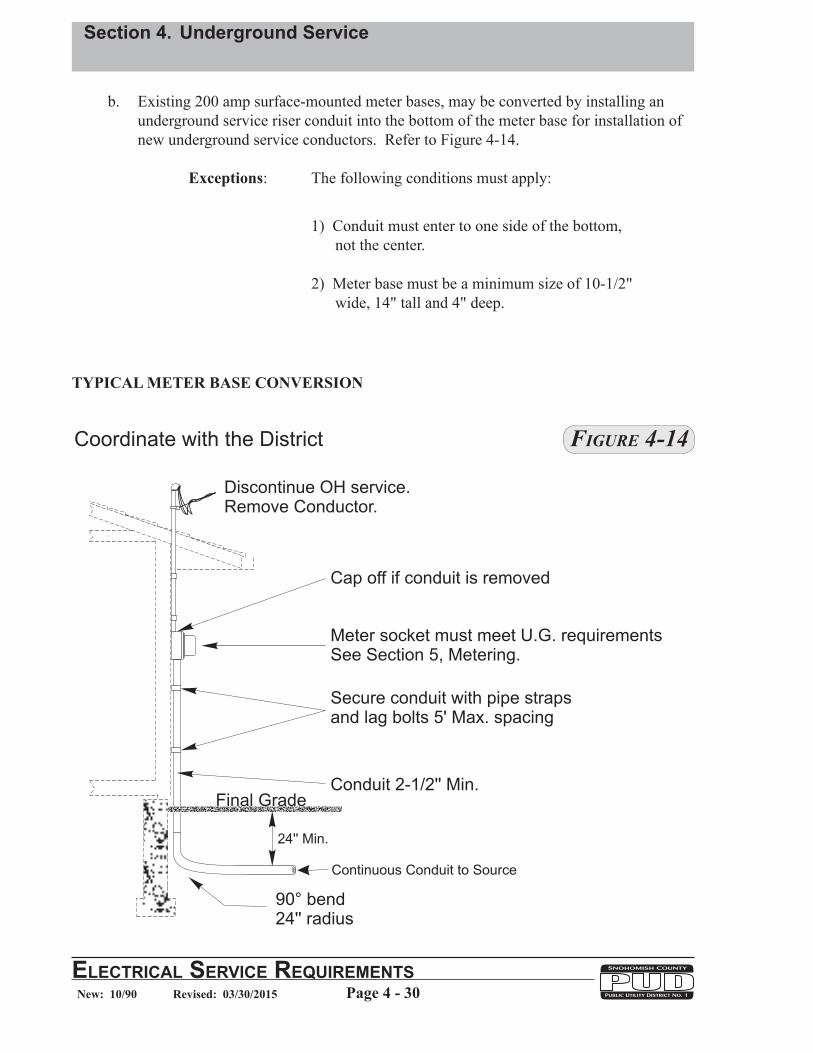
TYPICAL METER BASE CONVERSION
b. Existing 200 amp surface-mounted meter bases, may be converted by installing an underground service riser conduit into the bottom of the meter base for installation of new underground service conductors. Refer to Figure 4-14.
Exceptions: The following conditions must apply:
1) Conduit must enter to one side of the bottom, not the center.
2) Meter base must be a minimum size of 10-1/2" wide, 14" tall and 4" deep.
Figure 4-14

Section 4. Underground Service
ElEctrical SErvicE rEquirEmEntSPage 4 - 31New: 10/90 Revised: 03/30/2015
J. COMMERCIAL/APARTMENT SECONDARY PEDESTALS
1. The District shall install, own and maintain a pedestal on private property (normally at a property corner) as a source of secondary service to commercial or apartment buildings.
2. The customer may be required to install an additional vault for secondaries to terminate in non-standard installations.
3. The customer shall install, own and maintain all secondary service conductors on private property.
4. The District will make all secondary connections in the pedestal, provided that the customer-installed conductors are compatible with the District’s stock connectors.
5. A maximum number of secondary connections per phase shall be coordinated with the District.
6. Allowable conductor sizes shall be:
Aluminum or Copper: #2 to 750 kcm
7. If, through variance, other conductor sizes are allowed the customer shall be responsible for providing the required connectors, their installation and any future maintenance. Refer to Section 2, Variance Application.
8. The District will determine when the quantity and/or size of the secondary service conductors exceeds the practicality of a pedestal-type installation.
K. PADMOUNT TRANSFORMER EQUIPMENT, CLEARANCE
1. The customer shall be responsible for maintaining access to and clearance around all District-Owned padmount equipment. Refer to Section 2-O for access and Figure 4-15 for clearances.
2. Guard posts shall be furnished and installed by the customer when padmount equipment is located within an area of vehicular traffic (WAC 296-46B-450). The District shall determine the number and location of all guard posts. Refer to Fig. 4-16.

Section 4. Underground Service
Page 4 - 32ElEctrical SErvicE rEquirEmEntSNew: 10/90 Revised: 03/30/2015
PADMOUNT TRANSFORMER EQUIPMENT, CLEARANCE
Notes:1. All measurements are from the nearest metal part of the transformer.2. For variations and reduced clearance options, consult Engineering Standards.3. References: WAC 296-46B-450 and NESC 127.4. Some examples of non-combustible building/structure surfaces are brick,
concrete, steel, stone and fiber-cement siding material that complies withASTM E136, such as Hardiplank®.
5. A 3 ft minimum clearance is required between transformers and natural gasconnections, valves, gauges or meters.
6. Transformers shall not be located within 20 ft of fuel storage tanks or fueling points for highlycombustible liquids or gases (e.g., service station gasoline pumps and tanks, propane bulkdispensing tanks, etc.).
7. Transformers shall not be located within 10 ft of self-contained emergency diesel generators,or diesel fuel storage tanks or fueling points for emergency generators.
8. Enclosures for total underground mineral oil filled transformers, e.g., sub-surface vaults, mustnot be located within 8 ft of a doorway, operable window, stairway or fire escape. Adequatespace must be maintained above the enclosure so that a boom may be used to lift thetransformer from the enclosure.
9. Location of pad-mounted equipment shall not be more than 15 ft from access road ordriveway.
10. Finish grade at the transformer location must be such that leaking oil will flow away from thebuilding.
11. A clear and level working area shall be maintained in front of the transformer.12. Refer to Figure "A" for minimum working space requirements around pad-mounted
transformers located in areas with obstructions such as fences, walls, trees and shrubs.Landscaping which does not interfere with the installation, removal, operation andmaintenance of the transformer may be allowed within the working space.
Figure 4-15

Section 4. Underground Service
ElEctrical SErvicE rEquirEmEntSPage 4 - 33New: 10/90 Revised: 03/30/2015
NOTE:The Customer Shall Notify Utilities UndergroundLocation Center by calling 811 or 1-800-424-555548 Hours not less than two business days or morethan ten business days before the commencementof excavation or trenching to allow for the locationof existing underground utilities by theirrepresentatives (RCW 19.122.030). Contact theappropriate utility if conflicts occur.
TransformerGuard Post Locations
Guard posts are required by the State of Washington Electrical Inspection Division(WAC 296-46B-450) when transformers are located where exposed to vehicular traffic orother mobile type machinery.
Guard posts shall be furnished, installed and maintained by the contractor/customer at noexpense to the District.
Two types of guard posts are accepted by the District. One type is a 6" x 6'0" steel pipe setin and filled with
The District shall determine the number and establish the locationsof all guard posts. The exposed portion of the post shall be painted highway yellowor have a highway yellow thermoplastic polyethylene bumper post sleeve securelyinstalled over the post.
concrete. Another type is a 6” x 6’0” or a 9" x 6'0'' precast steelreinforced concrete post set in concrete.
Reinforced concrete posts can be purchased from Cuz Concrete, Arlington, WA orUtility Vault Company, Auburn, WA.
Bumper post sleeves can be purchased from Ideal Shield, 888-308-7290, or onlineat .www.idealshield.com
Refer to �gur e 4-16 above for c learances to padmount equipment .
Building Lines
PadmountInstallations
Guard Posts
Typical Locations
Figure 4-16

Section 4. Underground Service
Page 4 - 34ElEctrical SErvicE rEquirEmEntSNew: 10/90 Revised: 03/30/2015
L. CONNECTION TO PADMOUNT TRANSFORMERS, SECONDARY CABINETS, SECONDARY HANDHOLES OR SECONDARY PEDESTALS:
1. Under no circumstance shall the Customer penetrate the wall of an existing energized vault with either conduit or conductor. Only District personnel are authorized to penetrate into an existing energized vault.
2. The District shall make all primary and secondary connections on District owned transformers, secondary cabinets or secondary pedestals.
3. For commercial installations the customer shall install, own and maintain all secondary conductors from the service location to the secondary termination handhole. A minimum length of 15 feet of secondary cables per leg for vault sizes 4'8" x 4'8" or a minimum length of 25 feet of secondary cables per leg for vault sizes larger than 4'8" x 4'8" shall be provided inside the vault, sealed and identified.
For a Single or Duplex family residence, after the customer provides the conduit(s), trench and backfilling the District will own and maintain the secondary service conductors. In some installations these conductors may be provided and installed by the District or by the customer.
4. The District's engineer shall determine if J-boxes are required for a particular job. If J-boxes are needed, in addition to the vault requirements identified below, the customer shall provide a 4'8" square x 3'6" deep vault with a 4'8" square diamond plate lid to house the J-boxes.
5. Acceptable conductor sizes:
Commercial: Aluminum or Copper: #2 to 750 kcmil Residential: Aluminum Triplex: 1/0, 4/0 AWG or 350 kcmil
6. Acceptable conductor type:
600V XLP Type USE-2: Cable with ruggedized insulation is not acceptable
7. In certain cases it may be acceptable to connect single customer-owned service conductors directly to the low voltage terminals of a padmount transformer. Consult with the District's engineer to determine allowable cases. The vault option(s) and maximum number of secondary connections allowed per leg shall be as follows in Table 2 and Table 3. Consult with the District's engineer for acceptable vault option(s) prior to proceeding.
8. For commercial installations the customer shall install, own and maintain a secondary handhole adjacent to the transformer vault. The District will install conductors from the transformer to the secondary handhole and make all of the connections in that handhole.
9. For residential installations the secondary conductors from the transformer vault to the secondary terminations pedestal shall be installed, owned and maintained by the District.

Section 4. Underground Service
ElEctrical SErvicE rEquirEmEntSPage 4 - 35New: 10/90 Revised: 03/30/2015
10. The customer shall furnish and install the required conduit(s) between the transformer vault and secondary handhole(s).
11. All secondary conductors shall enter and lie in the secondary handhole(s) or compartment in the same direction, either clockwise or counter-clockwise without conflicting with each. Refer to Figure 4-17 for typical samples.
SECONDARY TRAINING IN VAULTS
Figure 4-17
All Secondary conductors shall enterand lie in the same directio n e itherclockwise or counter-clockwise andenter vaul t at proper corner as shown.4' 8''
4' 8''
90°
5/8'' x 8' Cu clad ground rodsRefer to Groundling Section 4-M.
Min. 15’ #2 bare(solid or stranded)SD Cu groundwire coiled in vault
7' 0''
Primary Conduit(s)Extend conduits5'' into vault
A minimum length of 15’ of secondary cables per legfor vault sizes 4’8” x 4’8” or a minimum length of 25’of secondary cables per leg for vault sizes larger than4’8” x 4’8” shall be provided inside the vault, identifiedand sealed to prevent moisture.
7'
90°4'-6''
Pulling Insert 5/8''Min. one each corner
Pulling Ironeach end
Secondary Conduit(s)
Set 2'' above final grade
Min. 15' of #2 bare (solid or stranded)SD Cu ground wire coiled inside the vault.
Compacted backfillrequired under padoverhanging
4' 8''
4' 8'' 4' 8''
4' 8''
90°
5/8'' x 8' Cu clad ground rodsRefer to Groundling Section 4-M.
Min. 15' of #2 bare(solid or stranded)SD Cu ground wirecoiled inside the vault.

Section 4. Underground Service
Page 4 - 36ElEctrical SErvicE rEquirEmEntSNew: 10/90 Revised: 03/30/2015
M. CONCRETE VAULTS, PADS AND HANDHOLES
When a vault is installed in areas where it may be exposed to pedestrian foot traffic a slip-resistant SlipNot type coating is required on the vault cover.
1. Residential customer vault site preparation.
a. The customer shall prepare the vault site in accordance with Figure 4-18.
b. The District will provide and install the vault, ground rods, ground wire and secondary service pedestal.
c. The vault hole shall be plumb, level and square.
d. The customer shall install the primary and the secondary conduits and pull ropes. The customer shall seal all ends with tapered, manufactured poly conduit plugs to keep out dirt prior to the installation of conductors.
e. After inspection and approval, the customer shall backfill the trenches prior to the installation of the electrical system.
60''
60''
36''
Continuous 2'' duct toproperty line as directedby PUD engineer.
Bell end by PUD
1/4" pull rope
Primary trench,conduitand pull rope.
After inspection approvalbackfill to within5 feet of hole.
Conduit to rise 8'' inlast 5' and terminate at centerof vault hole. Temporarilyseal ends of conduit prior toinstallation of conductor.
Pedestal by PUDTypical servicetrench by customer
24'' Min.
28''
ELECTRIC
NOTE:
Primary Trench and conduit to enter front ofvault site and off center to allow alignmentof conduit with mouse holes in vault.
Figure 4-18

Section 4. Underground Service
ElEctrical SErvicE rEquirEmEntSPage 4 - 37New: 10/90 Revised: 03/30/2015
2. Commercial Vault Installation Requirements
a. Specific job requirements will be determined by the District's engineer.
b. There shall be no express circuits allowed through vaults.
c. All vaults shall be designed and installed in a manner such that water from the vault will drain into an acceptable outlet. Water shall be all that is drained or pumped from vaults into acceptable outlets. Unacceptable outlets are salmon streams and storm drains. Vault drains shall not connect to storm drains, nor shall storm drains empty into a vault.
d. All vaults shall be installed to allow for the following minimum safe working clearances: • Padmount Transformer Vault: 10' in front and 3' on the rear or either side. • Secondary Cabinet Vault: 4' on all sides.
e. All transformer and switch cabinet vaults shall be set so that their lids are 2 inches above final grade. Switching vaults and secondary handholes may be set at final grade.
f. Two ground rods with 1/0 stranded bare copper wire are required at all secondary cabinet vaults. They shall be installed a minimum of 6 feet apart.
g. Two ground rods shall be required if installation is at the end of a lateral. They shall be installed a minimum of 6 feet apart.
h. Fifteen feet of #2 bare soft drawn copper ground wire (solid or stranded) shall be left coiled inside the vault.
i. All secondary conductors entering the handhole shall be protected at minimum by a piece of PVC conduit. This conduit shall be permanently sealed around its exterior and interior with cement grout.
j. All secondary conductors shall be labeled as to what they serve.
k. All secondary conductors shall extend a minimum length of 15 feet of secondary conductor per leg for vault sizes 4'8" x 4'8" or a minimum length of 25 feet of secondary conductor per leg for vault sizes larger than 4'8" x 4'8" shall be provided inside the vault, identified and sealed to prevent moisture.
l. Conduit shall enter the vault perpendicular to the vault walls which they are entering, and in a manner that ensures that all conductors can be trained to lay in the same direction (clockwise or counter-clockwise) and also in such a way as not to interfere with other conduit entrances. Refer to Figure. 4-17.
m. Conduit shall not enter at same corners of a vault.
n. Typically, conduit for primary conductor shall use lower knockout only, conduit for secondary conductors shall use upper knockout only, however, multiple conduit requirements shall use both upper and lower knockouts.

Section 4. Underground Service
Page 4 - 38ElEctrical SErvicE rEquirEmEntSNew: 10/90 Revised: 03/30/2015
o. Conduit for secondary jumpers shall be installed by the contractor between the transformer vault and the secondary handhole. The size and quantity will be determined by the District's engineer.
p. Cement grout is required to seal all holes and around all conduits. Refer to Figure 4–19.
q. Padmount cover specifications vary with the size of the padmount transformer or switch cabinet to be used. The District's engineer will specify cover size, access hole size and location.
r. When a handhole is used as a primary switching vault, a lid with a diamond plate access cover is required. Access opening size will be specified by the District's engineer.
s. Vaults and covers shall be located and oriented so that proper door clearance from buildings/obstructions may be maintained. Refer to Section 4-K.
t. Split vaults with removable divider walls shall have unistrut channel installed (9" ± 1" from top of wall to center line of channel) on each wall and on one side of the removable divider wall as shown in Figures 4-25, 4-26. In addition, removable divider wall shall have two (2) 5/8" diameter lifting inserts. The removable divider wall will be positioned so that the side with the unistrut channel will be installed facing the 41" section of the vault.
u. Bell ends are required on all commercial secondary conduits. The length of the conduit shall protrude into the vault just long enough to accommodate the bell end. The District will install the bell ends on the primary conduits.
v. Pulling irons, one at each corner, are optional for secondary vaults.
w. Pulling irons, one at each corner, are acceptable but not required in primary vaults unless specified by the District for a particular situation. Refer to Figure 4-19.
Exception: Pulling facilities are not required on J-Box or Open Bottom vaults. Refer to Figure 4-22 & Figure 4-23.
3. Identification
To identify their function, the word POWER, or ELECTRIC, shall be neatly and permanently marked in plain uppercase letters on the covers of subsurface electrical vaults and handholes that do not have pad-mounted equipment mounted on them. Letters shall be a minimum of 2” and a maximum of 3” in height. Letters shall be inscribed in the concrete cover or embossed on the metal door (where applicable). The identifying word shall be squarely in alignment with a vault edge for a neat appearance and shall be placed in a consistent location from one cover to the next. Where practical, the identifying word shall be aligned so that it can be read from the front of the vault, that is, from the side of the vault where the door latch or vault tag is located.

Section 4. Underground Service
ElEctrical SErvicE rEquirEmEntSPage 4 - 39New: 10/90 Revised: 03/30/2015
Figure 4-19
CONDUIT ENTRANCE AND GROUTING

Section 4. Underground Service
Page 4 - 40ElEctrical SErvicE rEquirEmEntSNew: 10/90 Revised: 03/30/2015
N. GROUNDING
1. Only one ground rod is required at each transformer vault when there is more then one vault in succession.
2. Two ground rods are required if installation is at the end of a lateral (the end vault). They shall be installed a minimum of 6 feet apart.
3. Two ground rods are required at all j-box vaults. They shall be installed a minimum of 6 feet apart. Refer to Figure 4-20.
4. Four ground rods are required at all feeder switch cabinet vaults and splice vaults. Refer to T&D Compatible Unit N0321 for grounding details.
5. Two ground rods with 1/0 stranded bare copper wire are required at all secondary cabinet vaults. They shall be installed a minimum of 6 feet apart.
Figure 4-20
Transformer pad size
as required
Embedded1'' x 3'' bronze plate
15' Min. #2 bare Cu SD ground wiresolid or stranded coiled in vault
15' Min. #2 bare Cu SD ground wiresolid or stranded coiled in vault
Two 5/8'' x 8'Cu clad ground rods
6'-0'' MIN.
Ground level
6'-0''
18'' Min.
Access cover
6'-0''
3' x 3' Diamondplate access door
Ground wire continuouswithout splice
Two 5/8'' x 8'Cu clad ground rods
Embedded1'' x 3'' bronze plate
Two 5/8'' x 8'Cu clad ground rods
3' x 3'Diamond plateaccess door
ELE
CT
RIC
ELECTRIC

Section 4. Underground Service
ElEctrical SErvicE rEquirEmEntSPage 4 - 41New: 10/90 Revised: 03/30/2015
O. VAULT ROOMS
Customer-furnished transformer vault rooms shall be submitted to and approved by the District prior to construction, in full compliance with NEC Article 450.41 through 450.48, for each individual installation and in accordance with the minimum requirements listed below:
1. The size of the transformer(s) shall determine the size of the vault, size of oil entrapment sill or sump, access size and amount of ventilation required.
2. A floor drain or sump shall be provided if there is a possibility of water entering the vault. Such drainage shall be located so that oil spillage cannot enter it.
3. The vault walls, floor and ceiling shall be solid concrete.
4. The room shall be illuminated by a minimum of 3 permanent fixtures and positioned so that all sides of the transformers are illuminated and arranged so that qualified individuals may change lamps or make repairs without violating the 2 foot minimum clearance requirement from energized primary conductors and equipment. Fixtures shall use T5 or T8 flourescent lamps or long life LED lamps and a light switch inside next to the latch side of the door. There shall be a minimum of 10 foot candles per square foot. Two duplex outlets with GFI protection shall also be installed on opposite ends of the vault walls.
5. Permanent transformer lifting eyes in the ceiling shall be provided.
6. 3-hour fire door(s) shall be provided in accordance with NEC 450.43 and a heavy duty panic bar exit device (Precision No. 4R0FL5103-603, 703A or 808A trim) and heavy duty automatic door closure (Stanley No. D-4550- Std.) shall be installed on the door(s). Key boxes and/or other panic bar and automatic door closures from alternate manufacturers are not acceptable. The door shall open towards egress of the room. During the construction phase, the panic bar exit device shall be equipped with a BEST Access Systems construction core on the outside of the door. When the vault room is ready to be energized, the District will furnish and change the construction core out to a District's "P" tumbler series which will then accept only the District's master "P" series key. The locking system shall limit access to qualified District employees only and not allow access to unqualified individuals (WAC 296-307-36230).
For lock, automatic closure and exit bar device information contact:
Contract Hardware, Inc Attention: Lynne Hufstedler 12100 NE 195th St. Suite 250 Bothell, WA 98011 Phone: 1-206-298-4770 Fax: 1-206-298-4777

Section 4. Underground Service
Page 4 - 42ElEctrical SErvicE rEquirEmEntSNew: 10/90 Revised: 03/30/2015
8. The District shall furnish and install a sign on the exterior door stating "Electrical Vault Room". In multiple unit complexes, the customer shall provide building identification signage.
9. It is the customer’s responsibility to insulate transformer vault rooms so that sound or transmitted vibration to other areas of the building are minimal. Transformer vault rooms must meet or exceed requirements of the applicable laws and noise ordinances of the Washington Administrative Code.
10. Foreign pipes and ducts shall not enter or pass through transformer vaults (NEC 450-47).
P. MAINTENANCE
Maintenance of District-Owned Underground Service Conductors:
The District will not charge for normal maintenance of underground service. If a fault occurs in a conductor as a result of improper backfill or dig-in damage caused by a customer or contractor, charges for repair will be determined by the District’s Claims Department and billed to the responsible party.

Section 4. Underground Service
ElEctrical SErvicE rEquirEmEntSPage 4 - 43New: 10/90 Revised: 03/30/2015
3'
20' Excess SecondaryConductor Coiled at Vault Entrance
(15' min. required inside vault )
When Conduit isused, stop it here4' from the Vault
No bell end on conduit(s)
Typical Existing Energized Vault
24'' Min.
3'
4'
SecondaryTop Knockouts
PrimaryKnockoutsBottom
DO NOTPENETRATE
Final Grade
ELECTRIC
DO NOTENTER
NOTE:The Customer Shall Notify Utilities UndergroundLocation Center by calling 811 or 1-800-424-555548 Hours not less than two business days or morethan ten business days before the commencementof excavation or trenching to allow for the locationof existing underground utilities by theirrepresentatives (RCW 19.122.030). Contact theappropriate utility if conflicts occur.
Figure 4-21
Q. INCREASING CAPACITY - EXISTING VAULT LOCATION
1. When adding secondary feeds to an existing energized padmount transformer, secondary handhole or pedestal, stop outside the vault and provide 20' of excess conductor and a work hole 3 foot wide x 3 foot deep x 4 foot back from vault for District personnel to penetrate the vault, extend the conductors and/or conduit(s) and make the connections.
2. Any costs associated with damage and repair to the existing primary, secondary(s) or ground wires are the responsibility of the customer/contractor.
3. Under no circumstance shall the Customer penetrate the wall of an existing energized vault with either conduit or conductor. Only District personnel are authorized to penetrate into an existing energized vault.
4. Contact engineering to determine which corner of an existing vault is available for the service to enter.

Section 4. Underground Service
Page 4 - 44ElEctrical SErvicE rEquirEmEntSNew: 10/90 Revised: 03/30/2015
Table 2 - 1Ø Xfmr Vault Selection Criteria
# of Customers1 1+
167 kVA or LessXfmr Loading
(Max. # Conductors/Leg)
4 6 8
Service Conductors NOT CONNECTED Directly to Xfmr
Required District Cat. ID’s
766206776015
Max. # and Size of Cables:1 Set of 350 – 4/0
2 Sets of 4/0 – 2/0 TPLX
See Figure 4-23
Service Conductors CONNECTED
Directly to Xfmr
Required District Cat. ID’s
766305See Figure 4-24
Service Conductors NOT CONNECTED Directly to Xfmr
Required District Cat. ID’s
Option 1765646781402100822
See Figure 4-25
Option 210008221001606
See Figure 4-26
Max. Size of Cables:500 kcmil
167 kVA or LessXfmr Loading
(Max. # Conductors/Leg)
1Ø Xfmr Vault Selection
Note: Maximum number of conductors allowed equals the total number of District and customer conductors. Consult with District engineer to determine how many customer conductors are allowed for a given transformer size.

Section 4. Underground Service
ElEctrical SErvicE rEquirEmEntSPage 4 - 45New: 10/90 Revised: 03/30/2015
Table 3 - 3Ø Xfmr Vault Selection Criteria
# of
Cus
tom
ers
11+
Xfm
r Size
Xfm
r Size
75 -
500
kVA
750
–25
00 k
VA75
-50
0 kV
A75
0 –
2500
kVA
Xfm
r Loa
ding
(Max
. # C
ondu
ctor
s/Le
g)Xf
mr L
oadi
ng(M
ax. #
Con
duct
ors/
Leg)
Xfm
r Loa
ding
(Max
. # C
ondu
ctor
s/Le
g)
6*
Serv
ice
Cond
ucto
rs
CON
NEC
TED
Dire
ctly
to X
fmr
For C
ondu
ctor
Siz
es L
ess
than
500
kcm
il:
Requ
ired
Dist
rict C
at. I
D’s
7663
13Se
e Fi
gure
4-2
7
For C
ondu
ctor
Siz
es 5
00
kcm
il an
d la
rger
:
Requ
ired
Dist
rict C
at. I
D’s
7656
4678
1444
1001
608
See
Figu
re 4
-28
Xfm
r Loa
ding
(Max
. # C
ondu
ctor
s/Le
g)
10*
12*
Serv
ice
Cond
ucto
rs
CON
NEC
TED
Dire
ctly
to X
fmr
For C
ondu
ctor
Siz
es 5
00
kcm
il an
d la
rger
:
Requ
ired
Dist
rict C
at. I
D’s
1001
689
1001
690
1001
691
See
Figu
re 4
-33
Serv
ice
Cond
ucto
rs
CON
NEC
TED
Dire
ctly
to X
fmr
For C
ondu
ctor
Siz
es L
ess
than
500
kcm
il:
Requ
ired
Dist
rict C
at. I
D’s
1000
825
See
Figu
re 4
-30
812
16
Serv
ice
Cond
ucto
rs
NO
T CO
NN
ECTE
D Di
rect
ly to
Xfm
r
Requ
ired
Dist
rict C
at. I
D’s
7656
4678
1444
1000
822
See
Figu
re 4
-29
Serv
ice
Cond
ucto
rs
NO
T CO
NN
ECTE
D Di
rect
ly to
Xfm
r
Requ
ired
Dist
rict C
at. I
D’s
Vaul
t:76
6313
1000
746
Seco
ndar
y Ca
bine
t:10
0020
9Se
e Fi
gure
s 4-3
1, 4
-36
3Ø X
fmr
Vaul
t Se
lect
ion
Serv
ice
Cond
ucto
rs
NO
T CO
NN
ECTE
D Di
rect
ly to
Xfm
r
Requ
ired
Dist
rict C
at. I
D’s
Vaul
t:76
5646
7814
4410
0074
710
0160
8Se
cond
ary
Cabi
net:
1000
210
See
Figu
res 4
-34,
4-3
7
1116
Serv
ice
Cond
ucto
rs
NO
T CO
NN
ECTE
D Di
rect
ly to
Xfm
r
Requ
ired
Dist
rict C
at. I
D’s
Vaul
t:10
0074
610
0082
5Se
cond
ary
Cabi
net:
1000
209
See
Figu
res 4
-32,
4-3
6
Serv
ice
Cond
ucto
rs
NO
T CO
NN
ECTE
D Di
rect
ly to
Xfm
r
Requ
ired
Dist
rict C
at. I
D’s
Vaul
t:10
0074
710
0168
910
0169
010
0169
1Se
cond
ary
Cabi
net:
1000
210
See
Figu
res 4
-35,
4-3
7
* If
requ
ired
# of
con
duct
ors p
er le
g ex
ceed
s m
ax. a
llow
able
am
ount
show
n, re
fer t
o op
tions
show
n fo
r 1+
cust
omer
sN
ote:
Max
imum
num
ber o
f con
duct
ors a
llow
ed e
qual
s the
tota
l nu
mbe
r of D
istri
ct a
nd c
usto
mer
con
duct
ors.
Con
sult
with
Dis
trict
eng
inee
r to
dete
rmin
e ho
w m
any
cust
omer
co
nduc
tors
are
allo
wed
for a
giv
en tr
ansf
orm
er si
ze.

Section 4. Underground Service
Page 4 - 46ElEctrical SErvicE rEquirEmEntSNew: 10/90 Revised: 03/30/2015
District Cat. ID 766214Figure 4-22
One 1Ø Open Bottom J-Box Vault
Note: This vault is used to support a junction box for single family residential and small commercial services. In small commercial applications the customer shall furnish and install the concrete vault, two ground rods, clamps and ground wire. Refer to Grounding, Section 4-N.

Section 4. Underground Service
ElEctrical SErvicE rEquirEmEntSPage 4 - 47New: 10/90 Revised: 03/30/2015
One 1Ø Customer Open Bottom Vault with Transformer
Transformer 50 kVA through 167 kVA Maximum of 4 conductors per leg.
Service conductors not connected directly to transformer. Pedestal - 13"W x 24"L x 15"D Maximum number and size of cables allowed: 1-Set of 350/4/0 Triplex & 2-Sets of 4/0-2/0 Triplex
District Cat. ID 776015(13"W x 24"L x 15"D)
Figure 4-23
District Cat. ID 766206
Note: This vault and pedestal combination is used for single family residential and small commercial services. In small commercial applications the customer shall furnish and install the concrete vault, two ground rods, clamps, and ground wire. Refer to Grounding, Section 4-N.

Section 4. Underground Service
Page 4 - 48ElEctrical SErvicE rEquirEmEntSNew: 10/90 Revised: 03/30/2015
One 1Ø Customer Transformer VaultTransformer 167 kVA or lessMaximum of 6 conductors per leg
Service conductors connected directly to transformer
Figure 4-24
District Cat. ID 766305

Section 4. Underground Service
ElEctrical SErvicE rEquirEmEntSPage 4 - 49New: 10/90 Revised: 03/30/2015
Option 1
District Cat. ID 781402
District Cat. ID 765646District Cat. ID 1000822
Figure 4-25
District Cat. ID 1000822
Figure 4-26
District Cat. ID 1001606
Option 2
One or More 1Ø Customers, Transformer Vault with Secondary Handhole Transformer 167 kVA or less Maximum of 8 conductors per leg
Maximum size of conductor 500 kcmil Service conductors not connected directly to transformer

Section 4. Underground Service
Page 4 - 50ElEctrical SErvicE rEquirEmEntSNew: 10/90 Revised: 03/30/2015
One 3Ø Customer Transformer VaultTransformer 75 - 500 kVA Maximum 6 conductors per leg Service conductors connected directly to transformer
One 3Ø Customer Transformer VaultTransformer 75 - 500 kVA Maximum 6 conductors per leg Service conductors connected directly to transformerFor conductor sizes 500 kcmil and larger a diamond plate access cover shall be provided.
District Cat. ID 766313
Figure 4-27
District Cat. ID 781444
District Cat. ID 1001608
District Cat. ID 765646
Figure 4-28

Section 4. Underground Service
ElEctrical SErvicE rEquirEmEntSPage 4 - 51New: 10/90 Revised: 03/30/2015
One or More 3Ø Customers, Transformer Vault with Secondary HandholeTransformer 75 — 500 kVA.Maximum of 8 conductors per leg.Service conductors not connected directly to transformer.
Figure 4-29
District Cat. ID 781444
District Cat. ID 765646
District Cat. ID 1000822
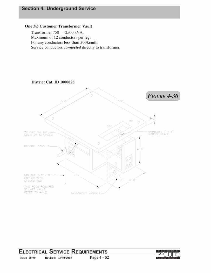
Section 4. Underground Service
Page 4 - 52ElEctrical SErvicE rEquirEmEntSNew: 10/90 Revised: 03/30/2015
Figure 4-30
District Cat. ID 1000825
One 3Ø Customer Transformer VaultTransformer 750 — 2500 kVA.Maximum of 12 conductors per leg.For any conductors less than 500kcmil.Service conductors connected directly to transformer.
District Cat. ID 1000746

Section 4. Underground Service
ElEctrical SErvicE rEquirEmEntSPage 4 - 53New: 10/90 Revised: 03/30/2015
District Cat. ID 766313
Figure 4-31Note:See Figure 4-36 for Secondary CabinetIllustration.
Refer to 4.M.2.d. for vault spacing requirements.
District Cat. ID 1000746
One or More 3Ø Customers, Transformer Vault with Secondary CabinetTransformer 75 — 500 kVA.Maximum 12 conductors per leg.Service conductors not connected directly to transformer.
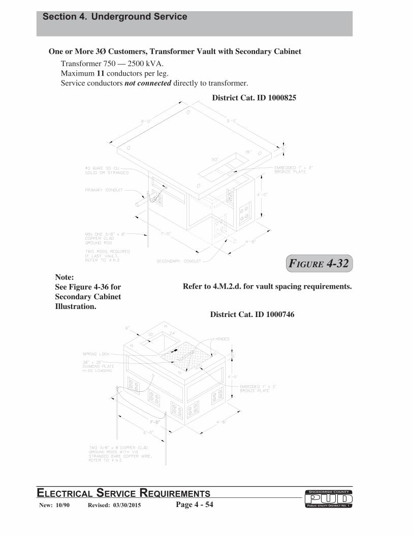
Section 4. Underground Service
Page 4 - 54ElEctrical SErvicE rEquirEmEntSNew: 10/90 Revised: 03/30/2015
District Cat. ID 1000825
Refer to 4.M.2.d. for vault spacing requirements.Note:See Figure 4-36 for Secondary CabinetIllustration.
Figure 4-32
District Cat. ID 1000746
One or More 3Ø Customers, Transformer Vault with Secondary CabinetTransformer 750 — 2500 kVA.Maximum 11 conductors per leg. Service conductors not connected directly to transformer.

Section 4. Underground Service
ElEctrical SErvicE rEquirEmEntSPage 4 - 55New: 10/90 Revised: 03/30/2015
One 3Ø Customer, Transformer Vault Transformer 750 — 2500 kVA. Maximum 10 conductors per leg. For conductor sizes 500kcmil and larger Service conductors connected directly to transformer.
District Cat. ID 1001689
District Cat. ID 1001690
Figure 4-33
District Cat. ID 1001691

Section 4. Underground Service
Page 4 - 56ElEctrical SErvicE rEquirEmEntSNew: 10/90 Revised: 03/30/2015
District Cat. ID 781444
One or More 3Ø Customers, Transformer Vault with Secondary Cabinet Transformer 75 — 500 kVA. Maximum 16 conductors per leg. Service conductors not connected directly to transformer.
District Cat. ID 765646
District Cat. ID 1001608
Figure 4-34
Refer to 4.M.2.d. for vault spacing requirements.Note:See Figure 4-37 for Secondary CabinetIllustration.
District Cat. ID 1000747

Section 4. Underground Service
ElEctrical SErvicE rEquirEmEntSPage 4 - 57New: 10/90 Revised: 03/30/2015
District Cat. ID 1001689
One or More 3Ø Customers, Transformer Vault with Secondary Cabinet Transformer 750 — 2500 kVA. Maximum 16 conductors per leg. Service conductors not connected directly to transformer.
District Cat. ID 1001690
District Cat. ID 1001691
Refer to 4.M.2.d. for vault spacing requirements.
Note:See Figure 4-37 for Secondary CabinetIllustration.
Figure 4-35
District Cat. ID 1000747

Section 4. Underground Service
Page 4 - 58ElEctrical SErvicE rEquirEmEntSNew: 10/90 Revised: 03/30/2015
District Cat. ID 1000209
Note:Install on District vault assembly Cat. ID 1000746.Refer to 4.N.5. for grounding.
Figure 4-36
Secondary Termination Cabinet20 connections per phase (maximum)
District Cat. ID 1000210

Section 4. Underground Service
ElEctrical SErvicE rEquirEmEntSPage 4 - 59New: 10/90 Revised: 03/30/2015
District Cat. ID 1000210
Secondary Termination Cabinet30 connections per phase (maximum)
Note:Install on District vault assembly Cat. ID 1000747.Refer to 4.N.5. for grounding.
Figure 4-37