Embed Size (px)
Citation preview

Section 4System Programming
This section provides step-by-step programming instructionsfor a proprietary telephone.
See MorePanasonic Manuals
www.voicesonic.comPhone: 877-289-2829
Panasonic Telephone Systems
www.voicesonic.comPhone: 877-289-2829
Panasonic Telephone Systems
Panasonic T7420, T7425, T7431, T7433, T7436, T7220, T7230, T7235, T7250, T7130, T7020, T7030, T7050, T7055

4-2 System Programming
4.1 General Programming Instructions
Default SettingThis system has a default factory setting. If any of theprogramming needs to be changed, you will find the necessaryinformation in Section 3, “Features”. This makes the system verysimple to install and customize as required by the customer. Anyrequired changes can be written in “Programming Tables”.
Required Telephone SetOne of the following telephone sets is required for SystemProgramming:• Digital Proprietary Telephone (DPT): KX-T7436, KX-T7433,
KX-T7431, KX-T7235,KX-T7230
• Analog Proprietary Telephone (APT): KX-T7130, KX-T7030
Extensions Used for ProgrammingConnect one of the above-mentioned telephone sets to either of thefollowing:
• Jack number 1• Jack programmed as a manager extension
To assign the manager extension, see Section 4.2 [006] “Operator /Manager Extension Assignment”.
User Programming (Manager Programming)Manager programming items are allowed for any displayproprietary telephone user in the system. See Section 4.1.4 “UserProgramming”.

System Programming 4-3
4.1.1 Using Proprietary Telephones
Soft Buttons and SHIFT Button on the Display DPTThree soft buttons are provided just below the display on thedisplay of Digital Proprietary Telephones (DPT), KX-T7433, KX-T7436, KX-T7230 and KX-T7235. The functions of these softbuttons vary as the programming procedures advance step by step.Those functions that are currently assigned to the buttons areshown on the lower line of the display. (See “Viewing the Display”on page 4-6 for more information on the display lines.) If the SHIFT button indicator is on, two functions are availablewith each soft button. To alternate between the two functions,press the SHIFT button on the right side of the display.
Soft button variations
CLR NEXT
Soft 1 Soft 2 Soft 3 SHIFT
Type 1
Example:KX-T7230 Display
Buttons
SKP+ CLR NEXT
Soft 1 Soft 2 Soft 3 SHIFT
SKP- PREV
Soft 1 Soft 2 Soft 3 SHIFT
Press SHIFTto alternate
Type 2
-> SEL+ NEXT
Soft 1 Soft 2 Soft 3 SHIFT
<- SEL- PREV
Soft 1 Soft 2 Soft 3 SHIFT
Type 3
Press SHIFTto alternate
A B C
Soft 1 Soft 2 Soft 3 SHIFT
a b c
Soft 1 Soft 2 Soft 3 SHIFT
Type 4
Press SHIFTto alternate

4-4 System Programming
During Normal Operation During Programming
(PAUSE) PAUSE / PROGRAM(SP-PHONE) NEXT
(REDIAL) PREV (PREVIOUS)(AUTO ANSWER / MUTE) SELECT(FLASH or FLASH/RCL) FLASH
(TRANSFER) CLEAR(FWD/DND)
(CONF) – / (INTERCOM) SECRET
(AUTO DIAL / STORE) STORE(HOLD) END
4.1.1 Using Proprietary Telephones
SKP+ SEL NEXT
Soft 1 Soft 2 Soft 3 SHIFT
SKP- CLR PREV
Soft 1 Soft 2 Soft 3 SHIFT
Type 5
Press SHIFTto alternate
InstructionsSELECTCLEAR
Soft buttonSEL+,SEL-,or SEL
CLR
You can use either the soft buttons or the overlay buttons. (Foroverlay buttons, refer to “Using the Overlay” below.)Throughout programming you will see instructions such as “PressPREV”. If you use soft buttons, this means press SHIFT, releaseSHIFT and then press Soft 3. The (PREV) function is performed.
Note If you use soft buttons and if programming instructions tell you to pressthe following buttons, you may press soft buttons shown below.
Using the OverlayA programming overlay is packed with the telephone at the factory.This overlay should be used at all times while in programmingmode since the functions of the telephone keys change while inprogramming mode as follows: (The original functions are inparentheses.)

System Programming 4-5
4.1.1 Using Proprietary Telephones
SECRET PAUSEPROGRAM CLEAR
STORE
FLASH/RCL SELECT
ENDPREV NEXT
ABC DEF
JKL MNOGHI
TUV WXYZ
OPER
PQRS
SHIFTSoft-1 Soft-2 Soft-3
SECRET PAUSEPROGRAM CLEAR
STORE
FLASH/RCL SELECT
ENDPREV NEXT
ABC DEF
JKL MNOGHI
TUV WXYZ
OPER
PQRS
SHIFTSoft-1 Soft-2 Soft-3
PROGRAM
VOLUME
SHIFT
1
4GHI
7PRS
5JKL
8TUV
0OPER
2ABC
6MNO
9WXY
3DEF
FLASHPREV END
STORE
SELECT
NEXT
SECRET PAUSE CLEAR
Soft-1 Soft-2 Soft-3
SECRET PAUSE CLEAR
PROGRAM
Soft 1 Soft 2 Soft 3
SHIFT
VOLUME
1
4GHI
7PRS
5JKL
8TUV
0OPER
2ABC
6MNO
9WXY
3DEF
FLASHPREV END
STORE
SELECT
NEXT
Location of Controls with the OverlayThe pictures below show the functions of the buttons of the KX-T7433, KX-T7436, KX-T7230 and KX-T7235 while inprogramming mode. KX-T7431 is the same as KX-T7433 exceptfor the Soft and SHIFT buttons.
KX-T7230 KX-T7235
KX-T7433 KX-T7436

4-6 System Programming
Viewing the Display The display gives you helpful information, such as what you shoulddo now, what you have done, etc..The KX-T7433, KX-T7436, KX-T7230 and the KX-T7235 utilizetwo information lines for programming. The upper line is called theMessage Line and the lower one is called the Function Line.The Message Line (upper) shows you what you should do or whatyou should select. It also allows you to confirm what you have justentered. The display capacity is 16 digits. If your entry exceeds thecapacity, you can shift the display by pressing or button.The Function Line (lower) shows the current function of the softbuttons. These functions change with the programming procedures.
SYS-PGM NO? →CLR NEXT
KX-T7230 Display
← Message Line← Function Line
SYS-PGM NO? →
CLR NEXT
KX-T7433 Display
← Message Line
← Function Line
SYS-PGM NO? →CLR NEXT
KX-T7436 / KX-T7235 Display
← Message Line← Function Line
Press PROGRAM (or PAUSE) + + # and enter your SystemPassword (default=1234).
Before entering the programming modeBefore entering programming mode, confirm that:
• Your telephone is on-hook.• No calls are on hold at your telephone.
Entering the programming mode
• The display shows the Initial Message: SYS-PGM NO? →
Note • If your telephone set does not have a PROGRAM button, substitute itwith the PAUSE button.
• If nothing is entered in five seconds after the PROGRAM (or PAUSE)button is pressed, it is cancelled.
• The System Password entered is not shown on the display. The SystemPassword can be changed by System Programming. Refer to Section4.3 [107] “System Password”.
• During the programming mode, your extension is treated as a busyextension.
• Only one proprietary telephone can be in programming mode at anyone time.
4.1.1 Using Proprietary Telephones
System Programming 4-7
4.1.2 Programming Methods
Example; NEXT NEXT NEXT
#1-1 #1-2 #2-1 #2-2 ...... PREV PREV PREV
Advancing to the next stageWhen “SYS-PGM NO? →” is displayed, you can select one of thefollowing:
• To go to program [000], press the NEXT button.• To go to another program, enter the 3-digit program address.
Rotation of jack numberEach jack of the Digital Super Hybrid System supports theconnection of a digital proprietary telephone and a single linedevice with different extension numbers (eXtra Device Port: XDPfunction). To program this function it is necessary to assign twoparts for each jack. The first part of jack one is 1-1. The secondpart of jack one is 1-2. The first part of jack two is 2-1 and so on.The NEXT and PREV buttons can be used to move from jack tojack as required in programs [003], [004] and [601] through [610].
Note The first part of a jack is for a DPT of a XDP-assigned jack. The secondpart is for a single line device. Program [600] “EXtra Device Port”assigns which jacks are XDP.
Storing your dataPress STORE to store your data.
• The STORE indicator lights red and a confirmation tone isemitted.
* Confirmation tone (one beep)After pressing STORE, you will hear a beep. This informs youthat storage is completed.
* Alarm tone (three beeps)If you hear this alarm, your entry is not valid.
Making another selection within the same program address• To make the next higher selection, press NEXT.• To make the previous selection, press PREV.• To make a specific selection, press SELECT and then enter the
number.

4-8 System Programming
4.1.2 Programming Methods
Going to another program addressAfter pressing STORE, you can go to another program with eitherof the following two methods:
(1) • To go to the next larger program address:Press Soft 1 (SKP+) or VOLUME (DOWN).
• To go to the next smaller program address:Press SHIFT + Soft 1 (SKP–) or VOLUME (UP).
(2) To go to a specific program address:Press END, then enter the Program Address.
Method (1) is useful when you want to perform a series ofprograms consecutively. For example, to change the programmingin addresses [000] to [008], use this method. You can move from[000] to [001], from [001] to [002], and so on by pressing theSKP+ or VOLUME . You can move in reverse order from[008] to [007], etc. by pressing the SKP– or VOLUME . This method can also be used to move between neighboringprogram groups: For example, you can move between the programaddresses [008] and [100], [116] and [200], and so on. Also, youcan move between the smallest program address [000] and thelargest one [991].Method (2) is useful when you wish to jump to another programaddress. For example, you have just finished with program [006]and now you want to go to program [301]. Neither SKP+/VOLUME nor SKP–/VOLUME is convenient in this case.So you should press END and enter 301.
Confirming the entriesYou may review the stored programming without making anychanges.
Going back to the operation modeTwo ways are available to go back to the operation mode:
(1) Lift the handset while in programming mode.(2) When the Initial Message: SYS-PGM NO? → is
displayed, press the PROGRAM (or PAUSE) button. (To display the Initial Message, press END.)
Note The following programming instructions assume that you have alreadyentered the programming mode and that you will use Method (2).

System Programming 4-9
4.1.3 Entering Characters
You can enter characters to store names or messages in the followingprograms by using the dialing key pad, buttons or the Jog Dial.[002] System Speed Dialing Name Set [111] Caller ID Name Set[004] Extension Name Set [417] Outside Line Name[008] Absent Message AssignmentSee the Combination Tables below.
Combination Tables
Rotating Jog Dial (Pulses)
Keys
1234567890
#
01234567890
*#
1QADGJMPTW
/$
2qadgjmptw!+%
3RBEHKNQUX?–&
4rbehknqux.=@
5SCFILORVY,<(
6scfilorvy’>)
7TDGJMPSWZ:#A
8tdgjmpswz;$a
Combination Table 2
Note • The alphabetical characterscorrespond to the letters shownon the twelve dialing keys on theproprietary telephone. (exceptsymbols)
• In Combination Table 1:If your telephone is a KX-T7431,do not use the provided SELECTbutton. Use the AUTOANSWER/MUTE button whichbecomes the SELECT buttonwhen using the overlay.
• In Combination Table 2:If you keep rotating the Jog Dial,all of the characters in the tablewill be displayed.
Pressing SELECT
(Times)
SHIFT & SoftCombination
Keys
1234567890
#
01234567890
*#
S1SHIFT +
S1 S2SHIFT +
S2 S3SHIFT +
S3SHIFT +SHIFT +S1
SHIFT +SHIFT +S2
1QADGJMPTW
/$
2qadgjmptw.+%
3ZBEHKNQUX,–&
4zbehknqux’=@
5!CFILORVY:<(
6?cfilorvy;>)
7
S
Z
8
s
z
Combination Table 1

4-10 System Programming
4.1.3 Entering Characters
Please see the following example which shows how to select adesired character. For example, to select the letter “M”:Select either of the following three methods:
(1) Using the SHIFT and Soft buttons(for KX-T7433 / KX-T7436 / KX-T7230 / KX-T7235 only) * See Combination Table 1.1. Press 6. (“M” belongs to “6”.)
• The Function Line shows: M N O2. Press the Soft 1 (M) button.(Press SHIFT to display the lower case of the above letters.)
(2) Using the SELECT button* See Combination Table 1.1. Press 6. (“M” belongs to “6”.)2. Press the SELECT button once.
• Pressing the SELECT button an appropriate number oftimes gives you the desired letter. Pressing SELECTtwice gives the letter “m”, pressing three times gives “N”,and so on.
(3) Using the Jog Dial(for KX-T7431 / KX-T7433 / KX-T7436 only) * See Combination Table 2.1. Press 6. (“M” belongs to “6”.)2. Rotate the Jog Dial one pulse.
• Rotating the Jog Dial an appropriate number of pulsesgives you the desired letter. Rotating the Jog Dial twopulses gives the letter “m”, rotating three pulses gives“N”, and so on.
OR
1. Press any dialing keypad.2. Rotate the Jog Dial until the desired character appears.
• If you keep rotating the Jog Dial, all of the characters willbe displayed. For example, If you rotate the Jog Dial afterpressing 2, characters will appear in the following order: A a B b ···· Z z (space) ! ? . , ’ : ; * / + – = < ># $ % & @ ( ) A a B b ····

System Programming 4-11
4.1.3 Entering Characters
1. Enter 6.
2. Press Soft 1 (M).
3. Enter 4.
4. Press SHIFT.
5. Press Soft 3 (i).
6. Enter 5.
7. Press Soft 2 (k).
8. Enter 3.
9. Press Soft 2 (e).
The display shows:6
M N O
MM N O
M4G H I
M4g h i
Example of entering characters: to enter “Mike”:Using method (1) * See Combination Table 1.
Miked e f
Mig h i
Mi5j k l
Mikj k l
Mik3d e f
Using method (2)* See Combination Table 1.
The display shows:1. Enter 6. 62. Press SELECT. M3. Enter 4. M44. Press SELECT six times. Mi5. Enter 5. Mi56. Press SELECT four times. Mik7. Enter 3. Mik38. Press SELECT four times. Mike

4-12 System Programming
4.1.3 Entering Characters
Using method (3)* See Combination Table 2.
The display shows:1. Enter 6. 62. Rotate Jog Dial one pulse. M3. Enter 4. M44. Rotate Jog Dial six pulses. Mi5. Enter 5. Mi56. Rotate Jog Dial four pulses. Mik7. Enter 3. Mik38. Rotate Jog Dial four pulses. Mike
OR
1. Enter 2. 22. Rotate Jog Dial until “M” appears. M3. Enter 2. M24. Rotate Jog Dial until “i” appears. Mi5. Enter 2. Mi26. Rotate Jog Dial until “k” appears. Mik7. Enter 2. Mik28. Rotate Jog Dial until “e” appears. Mike
Notes • To erase all the letters, press CLEAR.• To erase the last letter, press .

System Programming 4-13
4.1.4 User Programming Mode
Some programming items are accessible by any display proprietarytelephone user in the system.The programming items are listed below:[000] Date and Time Set[001] System Speed Dialing Number Set[002] System Speed Dialing Name Set[003] Extension Number Set[004] Extension Name Set[005] Flexible CO Button Assignment[006] Operator/Manager Extension Assignment[008] Absent Message[009] Quick Dial Number Set
Entering the user programming modeYou can access these programs by entering the User ProgrammingMode as follows:Before entering the mode, confirm that:• Your telephone is on-hook.• No calls are on hold at your telephone
After entering the mode, perform the same programming steps asthe system programming steps in each program address.
Note • If your telephone set does not have a PROGRAM button, substitute itwith the PAUSE button.
• If nothing is entered in five seconds after the PROGRAM (or PAUSE)button is pressed, it is cancelled.
• The User Password is not shown on the display. The password can bechanged by system programming. Refer to Section 4.3 [120] “UserPassword”.
• During the programming mode, your extension is treated as a busyextension.
• Only one proprietary telephone can be in programming mode at any onetime.
Press PROGRAM (or PAUSE) + + and enter the UserPassword (default: 1234)

4-14 System Programming
4.1.5 Programming Example
Description (4) Used to program the System SpeedDial numbers. These numbers areavailable to all extension users. Thereare 100 numbers from 00 through 99.
Selection (5) • Speed dial number: 00 through 99• Telephone number: 24 digits (max.)
Default(6) All speed dial numbers – Not stored
Programming(7) 1. Enter 001.(8)
Display: 001 SYS SPD DIAL(9)
2. Press NEXT.(10)
Display: SPD Code?→(11)
3. Enter a speed dial number.
To enter speed dial number 00,you can also press NEXT.
Display example: 00:Not
Stored(12)
4. Enter a telephone number. (13)
To delete the current entry, pressCLEAR. (14)
To change the current entry, pressCLEAR and the new number.
5. Press STORE.(15)
6. To program another speed dialnumber, press NEXT orPREV, or SELECT and thedesired speed dial number.(16)
7. Repeat steps 4 through 6. (17)
8. Press END. (18)
System Speed Dialing Number Set(3)
4.2 Manager Programming(2)001(1) (1) Program address: This address is printed at the topof every page to allow you to quickly find thedesired program.
(2) Running title: tells you which group the programbelongs to.
(3) Program title.
(4) Provides a more detailed description of theprogram.
(5) Shows you choices that you can assign.
(6) Shows you the default (factory setting).
(7) Shows you programming procedures step by step.
• While programming, use the overlay.
• Before starting to program, enter theprogramming mode. (See “Entering theprogramming mode” on page 4-6.)
(8) Enter the program address.
(9) The display shows the program title. If yourtelephone has soft buttons, the lower line showsthe functions that are currently assigned to them.
(10) Press either Soft 3 (NEXT) shown on the displayor the NEXT shown on the overlay.
(11) The message line advises you to enter a speed dialnumber.
(12) If the telephone number has already been stored,the number is displayed.
(13) Enter the telephone number that you want to store.Your entry is displayed as you enter the digits.
(14) Pressing CLEAR erases the whole entry.
(15) Your entry is now stored.
The indicator lights red and a confirmation tonelets you know that storage is complete.
(16) Select the best way for you to store another speeddial number. Pressing the NEXT / PREV allowsyou to select the next higher / lower speed dialnumber. You can also keep pressing them until thedesired one is displayed. If you press SELECT
Sample of Description Explanation
The following programming instructions assume that you havealready entered the programming mode and that you will employmethod (2) on page 4-8. Example: Program [001] “System Speed Dialing Number Set”

System Programming 4-15
4.1.5 Programming Example
Conditions (19) • Each speed dial number has amaximum of 24 digits. The validcharacters are 0 through 9, and #keys, FLASH or FLASH/RCL,PAUSE, SECRET and – (hyphen)buttons.
•••••
Feature References(20) Section 3, FeaturesSpecial Display Features
— Call Directory System Speed Dialing
and the desired speed dial number, the selectedcode is displayed.
(17) You can continue to program another entry.
(18) After you have stored all your entries, finish thisprogram by pressing END. After pressing ENDyou can go to any program address you desire.You can return to the Initial Message mode anytime by pressing END.
To go to the next lager program address, do notpress END but press Soft 1 (SKP+) orVOLUME .
To go to the next smaller program address, do notpress END but press SHIFT + Soft 1 (SKP-) orVOLUME .
(19) Tells you what you should notice or consider whendoing the programming.
(20) Lists all of the features related to theprogramming. These features are described inSection 3.
Sample of Description Explanation
4.2 Manager Programming001
System Speed Dialing Number Set (contd.)
Program Address[000] – [009]
[100] – [148]
[200] – [219]
[300] – [334]
[400] – [417]
[500] – [509]
[600] – [610]
[800] – [817]
[990] – [991]
Programming GroupManager Programming
System Programming
Timer Programming
TRS / ARS Programming
Outside LineProgramming
COS Programming
Extension Programming
Resource Programming
Option Programming
DescriptionThese programs may be accessed by thesystem manager of the customer to meetfrequent changes requested by the customer.
Entire system programming.
Flexible system timer setting.
Assignment of Toll Restriction and AutomaticRoute Selection (ARS).
Setting of outside line values.
Setting of Class of Service (COS).
Setting of extension values.
Assignment of customer-supplied peripheralsconnected to the system.
Used to answer the user’s requirements ortroubles, if needed.
Programming Structure

4-16 System Programming
4.2 Manager ProgrammingDate and Time Set
000
Description Sets the current date and time. A 12 hour clock or 24 hour clockcan be selected.
Selection • Year: 00 through 99• Month: Jan. through Dec.• Day: 1 through 31• Day of the week: SUN / MON / TUE / WED / THU / FRI / SAT• Hour: 1 through 12• Minute: 00 through 59• AM / PM• Clock hour: 12 or 24
Default '97 Jan. 1 WED 12:00 AM 12
Programming 1. Enter 000.
Display: 000 DATE / TIME
2. Press NEXT.
Display example: ’97 Jan. 1 WED
3. Enter the year.
To change the current entry, press CLEAR and enter the new year.
4. Press .
5. Keep pressing SELECT until the desired month is displayed.
6. Press .
7. Enter the day.
To change the current entry, press CLEAR and enter the new day.
8. Press .
NOTICEIt is assumed that you have read Section 4.1 “General Programming Instructions”. Softbutton usage is explained in that section, therefore no references will be made to them inthe following instructions. The soft buttons can be used in place of the overlay keys at anytime.

System Programming 4-17
4.2 Manager ProgrammingDate and Time Set (contd.)
000
9. Keep pressing SELECT until the desired day of the week isdisplayed.
10. Press STORE.
11. Press NEXT.
Display example: 12:00 PM 24
12. Enter the hour.
To change the current entry, press CLEAR and enter the new hour.
13. Press .
14. Enter the minute.
To change the current entry, press CLEAR and enter the new minute.
15. Press .
16. Press SELECT for AM or PM.
17. Press .
18. Press SELECT for 12 or 24 (clock hour).
19. Press STORE.
20. Press END.
Conditions • After changing an entry, you can press STORE. You do not have to perform the rest of the steps.
• To return to a previous field, press in steps 4 through 9 and steps13 through 18.
• If you hear an alarm after pressing STORE, check that the date is valid.• The clock starts immediately after the STORE button is pressed.• You cannot leave an entry empty.• Program [990] “System Additional Information, Field (30)” is used to
enable the automatic time adjustment by Caller ID information once aday.
Feature References Section 3, FeaturesDisplay, in Idle

4-18 System Programming
4.2 Manager ProgrammingSystem Speed Dialing Number Set
001
Description Used to program the System Speed Dial numbers. These numbersare available to all extension users. There are 100 numbers from 00to 99.
Selection • Speed dial number: 00 through 99• Telephone number: 24 digits (max.)
Default All speed dial numbers – Not stored
Programming 1. Enter 001.
Display: 001 SYS SPD DIAL
2. Press NEXT.
Display: SPD Code?→
3. Enter a speed dial number.
To enter speed dial number 00, you can also press NEXT.
Display example: 00:Not Stored
4. Enter a telephone number.
To delete the current entry, press CLEAR.
To change the current entry, press CLEAR and enter the new number.
5. Press STORE.
6. To program another speed dial number, press NEXT orPREV, or SELECT and the desired speed dial number.
7. Repeat steps 4 through 6.
8. Press END.
Conditions • Each speed dial number has a maximum of 24 digits. The validcharacters are 0 through 9, the and # keys, and the FLASH orFLASH/RCL, PAUSE, SECRET and – (hyphen) buttons.
– To store a flash signal, press FLASH or FLASH/RCL.Note: The stored flash will only be effective during a call.
(Refer to Section 3, “External Feature Access”.)– To store a hyphen, press the “–” button.– To store a pause, press PAUSE.
(Refer to Section 3, “Pause Insertion, Automatic”.)

System Programming 4-19
4.2 Manager ProgrammingSystem Speed Dialing Number Set (contd.)
001
– To store a feature number to convert pulse signals to DTMF (DualTone Multi-Frequency) signals, press the and # keys.(Refer to Section 3, “Pulse to Tone Conversion”.)
– To prevent displaying of all or part of the number, press SECRETbefore and after the secret number, or your entry will not be stored.(Refer to Section 3, “Secret Dialing”.)
• If you are storing an external number, include the line access code(default: 9, 81 through 83) before the number. When dialing, a pause isautomatically inserted after the code.
• If you are storing an account code, enter the account code before theline access code.(Refer to Section 3, “Account Code Entry”.)
• A number consisting of 25 digits or more can be stored by storing it intwo speed dial numbers. The line access code should be stored in thefirst speed dial number.
• To access another speed dial number in steps 3 through 6, pressSELECT and start with step 3.
• To display parts of the number which have scrolled off the display,press or .
• Program [002] “System Speed Dialing Name Set” is used to name thespeed dial numbers.
Feature References Section 3, FeaturesSpecial Display Features — Call Directory System Speed Dialing

4-20 System Programming
4.2 Manager ProgrammingSystem Speed Dialing Name Set
002
Description Assigns names to the system speed dial numbers assigned inprogram [001] “System Speed Dialing Number Set”. KX-T7235,KX-T7431, KX-T7433, and KX-T7436 telephones can show thestored name during System Speed Dialing.
Selection • Speed dial number: 00 through 99• Name: 10 characters (max.)
Default All speed dial numbers – Not stored
Programming 1. Enter 002.
Display: 002 SYS SPD NAME
2. Press NEXT.
Display: SPD Code?→
3. Enter a speed dial number.
To enter speed dial number 00, you can also press NEXT.
Display example: 00:Not Stored
4. Enter a name.For entering characters, see Section 4.1.3, “Entering Characters”. To delete the current entry, press CLEAR.To change the current entry, press CLEAR and enter the new name.
5. Press STORE.
6. To program another speed dial number, press NEXT orPREV, or SELECT and the desired speed dial number.
7. Repeat steps 4 through 6.
8. Press END.
Conditions • Speed dial numbers are programmed in program [001] “System Speed Dialing Number Set”.
• Each name has a maximum of 10 characters. • To go to another speed dial number in steps 3 through 6, press
SELECT and start with step 3.
Feature References Section 3, FeaturesSpecial Display Features — Call Directory

System Programming 4-21
4.2 Manager ProgrammingExtension Number Set
003
Description Assigns an extension number to each extension.
Selection • Jack number: 1 through 8 (-1 / -2)(-1 = first part, -2 = second part)
• Extension Number: 2 through 4 digits
Default Jack 1-1 through 8-1 = 11 through 18;Jack 1-2 through 8-2 = 21 through 28
Programming 1. Enter 003.
Display: 003 EXT NUMBER
2. Press NEXT.
Display: Jack NO?→
3. Enter a jack number.
To enter jack number 1, you can also press NEXT.
To select the second part (-2), press NEXT after entering the jacknumber.
Display: #1-1:EXT11
4. Enter an extension number.
To change the current entry, press CLEAR and enter the new number.
5. Press STORE.
6. To program another jack, press NEXT or PREV, orSELECT and the desired jack number.
7. Repeat steps 4 through 6.
8. Press END.
Conditions • There is a maximum of 16 extension numbers. Each extension numbercan be two, three, or four digits, consisting of 0 through 9. The and# keys cannot be used.
• An extension number is invalid if the first or second digits do not matchwith the program [100] “Flexible Numbering, (01) – (16) 1st through16th hundred extension blocks” setting. If one digit is assigned as theleading digit, some extensions have two digits and some have threedigits. If two digits are assigned, some have three digits and some havefour digits.

4-22 System Programming
4.2 Manager ProgrammingExtension Number Set (contd.)
003
• Two extension numbers can be assigned per jack. If eXtra Device Port(XDP) is disabled for the jack in program [600] “EXtra Device Port”,the extension number of the second part (X-2) is not available. (X=jacknumber)
• For an explanation of jack numbering, see “Rotation of jack number”on page 4-7.
• A double entry or incompatible entry is invalid including the program[118] “Voice Mail Extension Number Assignment”, [124] “PhantomExtension Number Assignment” and [813] “Floating NumberAssignment”. Valid entry examples are: 10 and 11; 10 and 110. Invalidentry examples are: 10 and 106; 210 and 21.
• Program [004] “Extension Name Set” is used to name the extensionnumbers.
Feature References Section 3, FeaturesDisplay, Call InformationEXtra Device Port (XDP)Flexible NumberingIntercom CallingSpecial Display Features — Call Directory

System Programming 4-23
4.2 Manager ProgrammingExtension Name Set
004
Description Assigns names to the extension numbers programmed in program[003] “Extension Number Set”.
Selection • Jack number: 1 through 8 (-1 / -2)(-1 = first part, -2 = second part)
• Name: 10 characters (max.)
Default All jacks – Not stored
Programming 1. Enter 004.Display: 004 EXT NAME SET
2. Press NEXT.Display: Jack NO?→
3. Enter a jack number.To enter jack number 1, you can also press NEXT.
To select the second part (-2), press NEXT after entering a jack number.
Display: #1-1:Not Stored
4. Enter a name.For entering characters, see Section 4.1.3 “Entering Characters”.
To delete the current entry, press CLEAR.
To change the current entry, press CLEAR and enter the new name.
5. Press STORE.
6. To program another jack, press NEXT or PREV, orSELECT and the desired jack number.
7. Repeat steps 4 through 6.
8. Press END.
Conditions • There is a maximum of 16 names. Each name has a maximum of 10characters.
• Program [003] “Extension Number Set” is used to assign extensionnumbers.
• For an explanation of jack numbering, see “Rotation of jack number”on page 4-7.
Feature References Section 3, FeaturesDisplay, Call InformationIntercom CallingSpecial Display Features — Call Directory

4-24 System Programming
4.2 Manager ProgrammingFlexible CO Button Assignment
005
Description Used to determine the use of the flexible CO buttons on proprietarytelephones from a centralized telephone.
Selection • Jack number: 1 through 8• Button Code (plus parameter, if required):
Default All jacks – CO buttons 1 through 3 = Single-CO 1 through 3;Ring tone type 2
Others = Not stored
Programming 1. Enter 005.Display: 005 FLEXIBLE CO
2. Press NEXT.
Display: Jack NO?→
†: Available when the Digital Super Hybrid System is connected to a Digital Proprietary Telephonecapable Panasonic Voice Processing System (one that supports digital proprietary telephoneintegration; e.g. KX-TVS100).
Parameter1 through 3 (Outside line number)
2 through 4 digits (Extension number)
16 digits max. (Telephone number)
None
None
None
None
None
None
2 through 4 digits (Phantom extension number)
2 through 4 digits (Extension number)
2 through 4 digits (Extension number)
2 through 4 digits (Extension number)
None
None
None
1 through 8 (ring tone type number)
Button Code0 (Single-CO)
1 (DSS)
2 (One-Touch)
3 (Message Waiting)
4 (FWD/DND)
5 (Save)
6 (Account)
70 (Conference)
71 (Log-In/Log-Out)
72 (Phantom Extension)
8 (Voice Mail Transfer)
90 (Two-Way Record)†
91 (Two-Way Transfer)†
92 (Live Call Screening)†
93 (Live Call Screening Cancel)†
(Loop-CO)
CO (ringer frequency)

System Programming 4-25
4.2 Manager ProgrammingFlexible CO Button Assignment (contd.)
005
3. Enter a jack number.To enter jack number 1, you can also press NEXT.
Display: PT–PGM Mode
4. Press the CO button which is changed to another button.The display shows the contents pre-assigned to the button.
Display example: CO-1
5. Enter a button code (plus parameter, if required).
To change the parameter, press CLEAR and enter the new parameter.
6. Press STORE.
7. • To program another CO button of the same jack, repeatsteps 4 through 6.
• To program another jack, press SELECT and repeat steps 3through 6.
8. Press END.
Canceling 1. Perform the same procedures as steps 1 through 4 above.
2. Enter 2.
3. Press STORE.
4. Press END.
Conditions • A centralized telephone is a telephone connected to jack 1 or a jackprogrammed as a manager extension in program [006] “Operator /Manager Extension Assignment”.
• The number of the CO buttons available depends on the telephone type.(Refer to Section 3 “Buttons on Proprietary Telephones”.) To program24 CO buttons, use the proprietary telephone, KX-T7425, KX-T7433,KX-T7436 or KX-T7230.
• If you press the same CO button again in step 5, you can select adesired ringer frequency for the CO button from eight types of ringtones. When you enter the tone type number (1 through 8), you willhear the selected tone type until STORE is pressed. This selection ispossible only for the CO buttons that have been assigned to Single-COor Loop-CO.
Feature References Section 3, FeaturesButton, Flexible Buttons on Proprietary Telephones

4-26 System Programming
4.2 Manager ProgrammingOperator / Manager Extension Assignment
006
Description Assigns the jack number for a manager and/or operators. Themanager extension can perform System Programming and managerservices. The operators have the ability to perform operatorservices.
Selection • OPE-1 (operator 1) / OPE-2 (operator 2) / MNGER (manager)• Jack number: 1 through 8
Default Operator 1 – Jack 1; Operator 2 and Manager – Not stored
Programming 1. Enter 006.
Display: 006 OP-1, 2, MGR
2. Press NEXT to program operator 1.
Display: OPE-1:Jack1
To program another item, you can also keep pressing NEXT or PREVuntil the desired one is displayed.
3. Enter a jack number.
To assign no operator or manager, press CLEAR.
To change the current entry, press CLEAR and enter the new jacknumber.
4. Press STORE.
5. To program another item, press NEXT or PREV.
6. Repeat steps 3 through 5.
7. Press END.
Conditions • Up to two operators and a manager can be programmed.• If the assigned jack is in eXtra Device Port mode, the proprietary
telephone jack is treated as the manager / operator extension.• If there is no operator or manager, press CLEAR in step 3.
Feature References Section 3, FeaturesManager Extension Operator

System Programming 4-27
4.2 Manager ProgrammingAbsent Messages
008
Description Used to program the absent messages. An absent message, if set bythe station user, is displayed on the calling extension’s telephone toshow the reason for the user’s absence.
Selection • Message number: 1 through 9• Message: 16 characters (max.)
Default 1: Will Return Soon2: Gone Home3: At Ext %%%4: Back at %%:%%5: Out Until %%/%%6: In a Meeting7 through 9: Blank (not stored)
Programming 1. Enter 008.
Display: 008 ABSENT MSG.
2. Press NEXT.
Display: MSG NO?→
3. Enter a message number.
To enter message number 1, you can also press NEXT.
Display example: MSG1:Will Return
4. Enter the message.
For entering characters, see Section 4.1.3 “Entering Characters”.
To delete the current entry, press CLEAR.
To change the current entry, press CLEAR and enter the newmessage.
5. Press STORE.
6. To program another message, press NEXT or PREV, orSELECT and the desired message number.
7. Repeat steps 4 through 6.
8. Press END.

4-28 System Programming
4.2 Manager ProgrammingAbsent Messages (contd.)
008
Conditions • There is a maximum of nine messages. Messages 1 through 6 are programmed at the factory but can be changed. Each message has a maximum of 16 characters.
• You can enter a maximum of seven “%” characters per message whichcan be programmed at each user’s extension. The station user can enter0 through 9, and # for the % characters. If the user enters digits lessthan the number of “%” characters, it is recommended to fill theremaining “%” characters with “#” or “ ”.
• If there are 4-digit extension numbers available in your system, add one“%” to Message 3.
• To display parts of the message which have scrolled off the display,press or .
Feature References Section 3, FeaturesAbsent Message Capability

System Programming 4-29
4.2 Manager ProgrammingQuick Dial Number Set
009
Description Stores up to eight quick dial numbers.
Selection • Location number: 1 through 8• Desired number: 16 digits (max.)
Default All location numbers – Not stored
Programming 1. Enter 009.
Display: 009 QUICK DIAL
2. Press NEXT.
Display: Location NO?→
3. Enter a location number.
To enter location number 1, you can also press NEXT.
Display example: 1:Not Stored
4. Enter a desired number.
To delete the current entry, press CLEAR.
To change the current entry, press CLEAR and enter the new number.
5. Press STORE.
6. To program another location, press NEXT or PREV, orSELECT and the desired location number.
7. Repeat steps 4 through 6.
8. Press END.
Conditions • A maximum of sixteen digits, consisting of 0 through 9, can beassigned to a quick dial number.
• Before programming, assign a feature number for each location first inprogram [100] “Flexible Numbering”.
Feature References Section 3, FeaturesQuick Dialing

4.3 System ProgrammingFlexible Numbering
100
4-30 System Programming
Description Assigns the leading digits of extension numbers and featurenumbers for system features.
Selection • Selection number: 01 through 71 (See “Feature Number List” onpages 4-32 and 4-33 for the correspondingfeatures.)
• Feature number: 1 or 2 digits (for selection numbers 01 through16); 1 through 3 digits (for selection numbers 17through 71)
Default See “Feature Number List” on pages 4-32 and 4-33.
Programming 1. Enter 100.
Display: 100 FLEX. NUMBER
2. Press NEXT.
Display: Select NO?→
3. Enter a selection number.
To enter selection number 01, you can also press NEXT.
Display example: 01. 1-EXT BL:1
4. Enter the feature number.
To delete the feature number, press CLEAR.
To change the current entry, press CLEAR and enter the new number.
5. Press STORE.
6. To program another selection, press NEXT or PREV, orSELECT and the desired selection number.
7. Repeat steps 4 through 6.
8. Press END.
To remove all the feature numbers except selection numbers(01) through (16) 1st through 16th extension blocks;
1. Enter 100.

4.3 System ProgrammingFlexible Numbering (contd.)
100
System Programming 4-31
2. Press NEXT.
3. Enter 00.
Display: All Feature CLR?
4. Press STORE.
5. Press END.
Conditions • Each extension block has one or two digits, consisting of 0 through 9.Assign the leading digits for extension numbers of the respectiveblocks.
• Assignment of extension blocks defines the limits for programs [003]“Extension Number Set”, [118] “Voice Mail Extension NumberAssignment”, [124] “Phantom Extension Number Assignment” and[813] “Floating Number Assignment”.
• Each feature number has one through three digits, consisting of 0through 9, , and #.
• If or # is included in a feature number, dial pulse telephone userscannot access the feature.
• Double entry and incompatible combinations are invalid. Valid entryexamples: 30 and 31, 210 and 211. Invalid entry examples: 5 and 5, 30and 301.
• If you delete a feature number, the feature cannot be used by dialingoperation.
• You can remove all the feature numbers except selections (01) through(16).
• To clear an extension block (01) through (16), it is required to changethe corresponding numbers assigned in program [003] “ExtensionNumber Set”, [118] “Voice Mail Extension Number Assignment”, [124]“Phantom Extension Number Assignment” and program [813]“Floating Number Assignment”.
Feature References Section 3, Features Flexible Numbering

4.3 System ProgrammingFlexible Numbering (contd.)
100
4-32 System Programming
Feature Number List
Number Feature Default01 1st hundred extension block 102 2nd hundred extension block 2
03 – 16 3rd through 16th hundred extension block None17 Operator call 018 Automatic line access / ARS 919 Outside line access 820 System speed dialing21 Station speed dialing 322 Station speed dialing programming 3023 Doorphone call 3124 Paging – external 3225 Paging – external answer / TAFAS answer 4226 Paging – group 3327 Paging – group answer 4328 Call pickup, outside line 429 Call pickup, group 4030 Call pickup, directed 4131 Call hold 5032 Call hold retrieve – intercom 5133 Call hold retrieve – outside line 5334 Last number redial #35 Call park / call park retrieve 5236 Account code entry 4937 Door opener 5538 External feature access 639 Station feature clear 79040 Message waiting 7041 Outgoing message 3642 Call forwarding / do not disturb 71043 Call pickup deny 72044 Data line security 73045 Call waiting / OHCA / whisper OHCA 73146 Executive busy override deny 73347 Pickup dialing 7448 Absent message 75049 Timed reminder 7650 Electronic station lockout 7751 Night service mode 7852 Parallel telephone mode 3953 Background music – external 35

4.3 System ProgrammingFlexible Numbering (contd.)
100
System Programming 4-33
Feature Number List (contd)
Number Feature Default54 LCS password 79955 Call log, incoming 5656 Call log lock, incoming 5757 Timed reminder, remote 758 Log-in / log-out 4559 Automatic callback busy cancel 4660 Walking COS 4761 Reserved None62 System working report 794
63 – 70 Quick dial location numbers 1-8 None71 Reserved None

4.3 System ProgrammingDay / Night Service Switching Mode
101
4-34 System Programming
Description This program is used to determine if night mode is setautomatically or manually.
Selection Manual / Auto (automatic)
Default Manual
Programming 1. Enter 101.
Display: 101 DAY/NT AUTO
2. Press NEXT.
Display example: D/N Mode:Manual
3. Keep pressing SELECT until the desired selection isdisplayed.
4. Press STORE.
5. Press END.
Conditions • If automatic switching is assigned, day / night mode is switched at the time programmed in [102] “Day / Night Service Starting Time”.
• The operator and manager can switch the day / night mode at any time.
Feature References Section 3, Features Night Service

4.3 System ProgrammingDay / Night Service Starting Time
102
System Programming 4-35
Description Sets the starting time on a day of the week basis, when automaticday / night switching is programmed in program [101] “Day / NightService Switching Mode”.
Selection • Day of the week selection number: 1 (Sunday) / 2 (Monday) / 3 (Tuesday) / 4 (Wednesday) / 5 (Thursday) / 6 (Friday) / 7 (Saturday) / (every day of theweek)
• Hour: 1 through 12 / Disable (no switching)• Minute: 0 through 59• AM / PM
Default Every day of the week – Day – 9:00 AM / Night – 5:00 PM
Programming 1. Enter 102.
Display: 102 DAY/NT CLOCK
2. Press NEXT.
Display: Day of Week?→
3. Enter the day of the week selection number.
To select Sunday, you can also press NEXT.
Display example: Sun-Day: 9:00 AM
To select night mode, press NEXT.
Display example: Sun-Nit: 5:00 PM
4. Enter the hour.
To set no switching, keep pressing SELECT until “Disable” isdisplayed and go to step 9.
If SELECT is pressed, the display shows the previous entry. If theprevious setting was “Disable”, press SELECT to enter the startingtime.
To change the current entry, press CLEAR and enter the new time.
5. Press .
6. Enter the minute.
To change the current entry, press CLEAR and enter the new minutes.
7. Press .

4.3 System ProgrammingDay / Night Service Starting Time (contd.)
102
4-36 System Programming
8. Press SELECT for AM or PM.
9. Press STORE.
10. To program another day / night mode or day of the week,press NEXT or PREV, or SELECT and the day of the weekselection number.
11. Repeat steps 4 through 10.
12. Press END.
Conditions • To select the desired day, you may keep pressing NEXT in step 3. To
assign every day of the week to one selection, press the key in step3. In this case, the display shows the contents programmed for Sunday.
• If day / night switching is not desired, select “Disable” in step 4.• You cannot leave the entry empty.
Feature References Section 3, Features Night Service

4.3 System ProgrammingAutomatic Access Outside Line Assignment
103
System Programming 4-37
Description Assigns the sequence in which outside lines will be accessed whenin Automatic Line Access mode. When a user dials the featurenumber for automatic line access (default=9) or presses the Loop-CO button, an idle line is searched for in the programmed outsideline order.
Selection • Outside line number: 1 through 3 in desired order
Default 123
Programming 1. Enter 103.
Display: 103 AUTO CO
2. Press NEXT.
Display example: Access:123
3. Enter the outside line numbers in priority from top tobottom.
To delete the current entry, press CLEAR.
To change the current entry, press CLEAR and enter the new order.
4. Press STORE.
5. Press END.
Conditions • Automatic Line Access feature works only if the Automatic RouteSelection mode is turned off in program [312] “ARS Mode”.
Feature References Section 3, Features Line Access, Automatic Line Preference – OutgoingLine Access, Direct

4.3 System ProgrammingAccount Codes
105
4-38 System Programming
Description Assigns the account codes for Account Code Entry, Verified – AllCalls and Verified – Toll Restriction Override modes. If Verified –All Calls is assigned in program [508] “Account Code EntryMode”, an account code is required to make an outside call. IfVerified – Toll Restriction Override is assigned, an account code isonly required for a toll call and overrides toll restriction.
Selection • Location number: 01 through 20• Account code: 10 digits (max.)
Default All locations – Not stored
Programming 1. Enter 105.Display: 105 ACCT CODES
2. Press NEXT.Display: Location NO?→
3. Enter a location number. To enter location number 01, you can also press NEXT.
Display example: 01:Not Stored
4. Enter an account code.To delete the current entry, press CLEAR.To change the current entry, press CLEAR and enter the new accountcode.
5. Press STORE.
6. To program another location, press NEXT or PREV, orSELECT and the desired location number.
7. Repeat steps 4 through 6.
8. Press END.
Conditions • Each verifiable account code has a maximum of 10 digits, consisting of0 through 9.
• Program [508] “Account Code Entry Mode” is used to select theAccount Code Entry mode.
• Account codes having “99” in any part or ending with “9” are invalid,as “99” is used as a delimiter when entering an account code.
Feature References Section 3, Features Account Code EntryToll Restriction Override by Account Code Entry

4.3 System ProgrammingStation Hunting Type
106
System Programming 4-39
Description Used to enable or disable hunting and set the Station Hunting typefor each extension group. There are six Station Hunting typesavailable: Circular, Terminating, Voice Mail (VM), AutomatedAttendant (AA), Ring Group and Uniform Call Distribution (UCD).If circular hunting is assigned for a group, all of the extensions inthe group are searched until an idle one is found. If terminatinghunting is assigned, searching stops at the extension which has thelargest jack number in the group. If VM hunting is assigned, all ofthe VM ports of an extension group are searched until an idle one isfound which allows Voice Mail Service. If AA hunting is assigned,all of the AA ports of an extension group are searched until an idleone is found which allows AA Service. If Ring Group is assigned,all of the extensions in the ring group ring simultaneously. If UCDis assigned, group members are hunted in a circular way.
Selection • Extension group number: 1 through 8, ( =all extensiongroups)
• Disable (no hunting) / Terminate (terminating) / Circular / VM(voice mail) / AA (automated attendant) / RING / UCD
Default All extension groups – Disable
Programming 1. Enter 106.Display: 106 STATION HUNT
2. Press NEXT.Display: EXT GRP NO?→
3. Enter an extension group number. To enter extension group number 1, you can also press NEXT.
Display example: Group1:Disable
4. Keep pressing SELECT until the desired selection isdisplayed.
5. Press STORE.
6. To program another extension group, press NEXT or PREV,or SELECT and the desired extension group number.
7. Repeat steps 4 through 6.
8. Press END.

4.3 System ProgrammingStation Hunting Type (contd.)
106
4-40 System Programming
Conditions • Program [602] “Extension Group Assignment” is used to assign theextension group members.
• The system supports a maximum of four jacks for connection to a VoiceProcessing System as VM or AA ports.
• To assign all extension groups to one selection, press the key in step3. In this case, the display shows the contents programmed forextension group 1.
Feature References Section 3, Features Ring Group Uniform Call Distribution (UCD)Station Hunting Voice Mail Integration

4.3 System ProgrammingSystem Password
107
System Programming 4-41
Description Assigns the password required for entering System Programmingmode and for maintenance from a personal computer.
Selection Password: 4 through 7 digits
Default 1234
Programming 1. Enter 107.
Display: 107 SYS PASSWORD
2. Press NEXT.
Display: Password:1234
3. Enter a password.
To change the current entry, press CLEAR and enter the newpassword.
4. Press STORE.
5. Press END.
Conditions • The password can be from four to seven digits long. The valid numbersare from 0 through 9.
• If less than four digits are entered, they are not stored.• You cannot leave the entry empty.
Feature References Section 3, Features System Programming with Personal ComputerSystem Programming with Proprietary Telephone

4.3 System ProgrammingAutomatic Hold by CO / DSS Button
108
4-42 System Programming
Description Enables or disables automatically holding an outside call when aDSS (Direct Station Selection) button or a CO button on aproprietary telephone is pressed. Through this assignment, eachbutton acts as follows:— Pressing the DSS button holds an outside call and quickly
transfers it to an extension without pressing the TRANSFERbutton.
— Pressing another CO button holds the current outside call.
Selection • Button: DSS or CO• Enable / Disable
Default DSS button – Enable, CO button – Disable
Programming 1. Enter 108.
Display: 108 AUTO HOLD
2. Press NEXT to program the DSS button.
Display example: DSS XFER:Enable
3. Keep pressing SELECT until the desired selection isdisplayed.
4. Press NEXT to program the CO button.
Display example: CO Hold :Disable
5. Keep pressing SELECT until the desired selection isdisplayed.
6. Press STORE.
7. Press END.
Conditions This assignment applies to all DSS and CO buttons on all proprietarytelephones in the system.
Feature References Section 3, FeaturesAutomatic Hold by CO ButtonOne-Touch Transfer by DSS Button

4.3 System ProgrammingCaller ID Code Set
110
System Programming 4-43
Description Sets the identification code of the calling party (Caller ID Code) toutilize a Caller ID Service provided by a specific central office(CO). If an ID Code transmitted from the CO is found in the CallerID Code Table, the caller’s ID Code or name given to the code inprogram [111] “Caller ID Name Set” is displayed on the telephone.This allows the called party to recognize the caller.
Selection • Location number: 001 through 100• Caller ID Code: 11 digits (max.)
Default All locations – Not stored
Programming 1. Enter 110.Display: 110 CALLER ID #
2. Press NEXT.Display: Location NO?→
3. Enter a location number. To enter location number 001, you can also press NEXT.
Display example: 001:Not Stored
4. Enter a Caller ID Code.To delete the current entry, press CLEAR.
To change the current entry, press CLEAR and enter the new code.
5. Press STORE.
6. To program another location, press NEXT or PREV, orSELECT and the desired location number.
7. Repeat steps 4 through 6.
8. Press END.
Conditions • Each Caller ID Code has a maximum of 11 digits, consisting of 0through 9.
• Program [111] “Caller ID Name Set” is used to give names to the CallerID Codes. If an ID Code is assigned a name, the called party’stelephone will show the name in place of the ID Code.
• Program [406] “Caller ID Assignment” is used to enable the Caller IDService on an outside line basis.
Feature References Section 3, Features Caller ID

4.3 System ProgrammingCaller ID Name Set
111
4-44 System Programming
Description With Caller ID Service, the calling party is displayed either by itsID Code or by its name. If the name display is required, use thisprogram to give a name to a caller ID Code stored in program [110]“Caller ID Code Set”.
Selection • Location number: 001 through 100• Caller ID Name: 15 characters (max.)
Default All locations – Not stored
Programming 1. Enter 111.
Display: 111 CALLER NAME
2. Press NEXT.
Display: Location NO?→
3. Enter a location number.
To enter location number 001, you can also press NEXT.
Display example: 001:Not Stored
4. Enter a Caller ID Name.
For entering characters, see Section 4.1.3 “Entering Characters”.
To delete the current entry, press CLEAR.
To change the current entry, press CLEAR and enter the new name.
5. Press STORE.
6. To program another location, press NEXT or PREV, orSELECT and the desired location number.
7. Repeat steps 4 through 6.
8. Press END.
Conditions • Caller ID Name corresponds to the Caller ID Codes stored in program[110] “Caller ID Code Set”.
• Each name has a maximum of 15 characters.
Feature References Section 3, Features Caller ID

4.3 System ProgrammingVM Status DTMF Set
113
System Programming 4-45
Description Sets the DTMF signals (“inband”) that are transmitted to the VoiceProcessing System (VPS), by the Panasonic telephone system,under all the dial and connect events which the VPS can occur. The following signals are sent to the VPS with the assigned DTMFsignals:
RBT (ringback tone) : This signal is sent when calling anextension.
BT (busy tone) : This is sent when the called extension isbusy.
ROT (reorder tone) : This is sent when the dialed number isinvalid.
DND (DND tone) : This is sent when the other extension hasDND assigned.
Answer : This is sent when the other extensionanswers the call.
Disconnect : This is sent when the other extensionhangs up.
Confirm (confirmation tone) : This is sent when the feature number for“Message Waiting Lamp” is valid.
FWD VM RBT (FWD to VM ringback tone) : Not available (reserved).
FWD VM BT (FWD to VM busy tone) : This is sent when the called extensionhas set Call Forwarding to VPS.
FWD EXT RBT (FWD to extension ringback tone) :Not available (reserved).
Selection • RBT / BT / ROT / DND / Answer / Disconnect / Confirm /FWD VM RBT / FWD VM BT / FWD EXT RBT
• DTMF signal number: 3 digits (max.)
Default RBT – 1; BT – 2; ROT – 3; DND – 4; Answer – 5; Disconnect – #9Confirm – 9; FWD VM RBT – 6; FWD VM BT – 7; FWD EXTRBT – 8
Programming 1. Enter 113.Display: 113 VM DTMF SET
2. Press NEXT to program ringback tone status.To program another status, keep pressing NEXT until the desiredstatus is displayed.
Display example: RBT :1

4.3 System ProgrammingVM Status DTMF Set (contd.)
113
4-46 System Programming
3. Enter a DTMF signal number. To delete the current entry, press CLEAR.To change the current entry, press CLEAR and enter the new number.
4. Press STORE.
5. To program another selection, keep pressing NEXT or PREVuntil the desired selection is displayed.
6. Repeat steps 3 through 5.
7. Press END.
Conditions • A DTMF signal number can have a maximum of three digits, consistingof 0 through 9, , # and PAUSE.
• The DTMF signals are sent to the extensions in the extension group thatis assigned as “VM” or “AA” in program [106] “Station HuntingType”.
Feature References Section 3, Features Voice Mail Integration

4.3 System ProgrammingVM Command DTMF Set
114
System Programming 4-47
Description Sets the DTMF (Dual Tone Multi-Frequency) command signalstransmitted to your Voice Processing System (VPS). There are fourcommands available: Leave Message; Get Message; AutomatedAttendant Service; Voice Mail Service. These commands are usedin the following ways:(A) If your VPS is used for Voice Mail (VM) Service(1) Call Forwarding / Intercept Routing to Voice MailIf a call is forwarded to the VPS, your system will send a mailboxnumber to the VM port. This allows the caller to leave a messagewithout knowing the mailbox number.• Required entries (selections):
LV-MSG (Leave Message): This command is transmitted to aVM port if a call is forwarded or intercepted and rerouted to theport. AA-SVC (Automated Attendant Service): If AA Service is set to“Start” in program [990], field (10), the “AA-SVC” command issent to a VM port if an incoming outside call is answered by theVM port.
• Other programming required (program addresses): [106]; [602];[609]; [990], field (10); [990], field (18)
(2) Hearing the message at the extensionIf the VPS receives a message and lights the MESSAGE buttonindicator of the dialed telephone, the telephone user can hear themessage by pressing the MESSAGE button.• Required entries (selections):
GETMSG (Get Message): This command is transmitted to a VMport when the message receiver presses the MESSAGE button.VM-SVC (Voice Mail Service): The “VM-SVC” command is acode transmitted preceding the “GETMSG” command above.This is effective to switch to VM port when an AA port lights theMESSAGE indicator.
• Other programming required (program addresses): [609]; [990],field (18)
(B) If your VPS is used for Automated Attendant (AA) ServiceAn AA port answers an incoming outside call to provide AAservices, such as call transfer, receiving a message. • Required entries (selections):
VM-SVC (Voice Mail Service): The “VM-SVC” command is acode transmitted before the “LV-MSG” code if an operatortransfers a call to an extension and then it is forwarded to an AAport so that the AA port can be switched to the VM porttemporarily.
• Other programming required (program addresses): [106], [602]

4.3 System ProgrammingVM Command DTMF Set (contd.)
114
4-48 System Programming
Selection • LV-MSG / GETMSG / AA-SVC / VM-SVC • DTMF signal number: 16 digits (max.)
Default LV-MSG – H; GETMSG – H; AA-SVC – #8 ; VM-SVC – #6
Programming 1. Enter 114.Display: 114 VM DTMF CMD
2. Press NEXT to program the LV-MSG command.To program another command, keep pressing NEXT until the desiredcommand is displayed.
Display example: LV-MSG:H
3. Enter a DTMF signal number. To delete the current entry, press CLEAR.To change the current entry, press CLEAR and enter the new number.
4. Press STORE.
5. To program another selection, keep pressing NEXT or PREVuntil the desired selection is displayed.
6. Repeat steps 3 through 5.
7. Press END.
Conditions • A command signal number can have a maximum of 16 digits,consisting of 0 through 9, , #, FLASH or FLASH/RCL andPAUSE.
• The FLASH or FLASH/RCL button is available only for LV-MSG andGETMSG commands to store “H” which means “Home Position”.
• If “H” is stored for “LV-MSG”, a mailbox number programmed inprogram [609] “Voice Mail Access Codes” or an extension number willbe sent to the VM port (Follow On ID function). If certain codes arerequired before and after the ID code, insert “H” between the codes, as“aaaHbbb”. If nothing is stored, it will operate as “H”.
• If “ H” is stored for “GETMSG”, a mailbox number programmed inprogram [609] “Voice Mail Access Codes” or an extension number willbe sent to the port succeeding the “ ”.
Feature References Section 3, Features Voice Mail Integration

4.3 System ProgrammingROM Version Display
116
System Programming 4-49
Description Confirms the version of ROM of the system.
Programming 1. Enter 116.
Display: 116 ROM VERSION
2. Press NEXT.
The display shows the ROM version of the system.
3. Press END.
Conditions • The out-of-service system number is unacceptable.
Feature References None
Display example: P011A30101A
Version Date

4.3 System ProgrammingVoice Mail Number Assignment †
117
4-50 System Programming †: Available when the Digital Super Hybrid System is connected to a DigitalProprietary Telephone capable Panasonic Voice Processing System (onethat supports digital proprietary telephone integration; e.g. KX-TVS100).
Description Assigns the jack number corresponding to the voice mail port fordata transmission to the Voice Processing System. The voice mailport is expandable to two ports.
Selection • Jack number: 2 through 8
Default All jacks — Blank
Programming 1. Enter 117.Display: 117 VMS PORT ASN
2. Press NEXT.Display example: M:# #
3. Enter a jack number.To delete the current entry, press CLEAR.
To change the current entry, press CLEAR and enter the new jacknumber.
4. Press to enter another jack number.
5. Repeat steps 3 through 4 to enter another jack number.
6. Press STORE.
7. Press END.
Conditions • Neither Jack number 1 nor the manager extension can be assigned as avoice mail port jack. The voice mail port jack cannot be assigned to amanager extension.
• The jack numbers correspond to the voice mail port in numerical order.Example: Stored jack numbers: Jacks 2, 3Jack 2=Voice mail numbers 1, 2; Jack 3= Voice mail numbers 3, 4
Feature References Section 3, FeaturesVoice Mail Integration for Digital Proprietary Telephones

4.3 System ProgrammingVoice Mail Extension Number Assignment †
118
System Programming 4-51†: Available when the Digital Super Hybrid System is connected to a DigitalProprietary Telephone capable Panasonic Voice Processing System (onethat supports digital proprietary telephone integration; e.g. KX-TVS100).
Description Assigns the extension number for the voice mail number. Thesenumbers can be used the same way extension numbers are used forstation access.
Selection • Voice mail number (VM): 1 through 4• Extension Number: 2 through 4 digits
Default VM-1=295, VM-2=296, VM-3=297, VM-4=298
Programming 1. Enter 118.
Display: 118 VM EXT #
2. Press NEXT.Display: VM NO?→
3. Enter a voice mail number.To enter voice mail number 1, you can also press NEXT.
Display: VM-1:#2-1:295
4. Enter an extension number.To change the current entry, press CLEAR and enter the new number.
5. Press STORE.
6. To program another voice mail number, press NEXT orPREV, or SELECT and the desired voice mail number.
7. Repeat steps 4 through 6.
8. Press END.
Conditions • You cannot leave an entry empty.• Double entries and incompatible entries for extension numbers are
invalid.• The display shows “VM-X:#Y-1:ZZZ” in step 3.
“X” means the voice mail number. “Y” means the jack number of thevoice mail port programmed in [117] “Voice Mail NumberAssignment”.“-1” of Y-1 means the first part of jack number in digital line. Y-2 means the second number of the jack number in digital line.
Feature References Section 3, FeaturesVoice Mail Integration for Digital Proprietary Telephones

4.3 System ProgrammingVoice Mail Extension Group Assignment †
119
4-52 System Programming †: Available when the Digital Super Hybrid System is connected to a DigitalProprietary Telephone capable Panasonic Voice Processing System (onethat supports digital proprietary telephone integration; e.g. KX-TVS100).
Description Assigns each voice mail number to a voice mail extension groupnumber.
Selection • Voice mail number (VM): 1 through 4, ( =all voice mail number)
• Voice mail extension group number (EXG) = 1 through 8
Default All voice mail numbers = EXG 1
Programming 1. Enter 119.Display: 119 VM EXT GROUP
2. Press NEXT.Display: VM NO?→
3. Enter a voice mail number.To enter voice mail number 1, you can also press NEXT.
Display example: VM-1:#2-1:EXG1
4. Enter the voice mail extension group number.To delete the current entry, press CLEAR.
To change the current entry, enter the new number.
5. Press STORE.
6. To program another voice mail number, press NEXT or PREV, or SELECT and the desired voice mail number.
7. Repeat steps 4 through 6.
8. Press END.
Conditions • The display shows “VM-X:#Y-1:EXG Z” in step 3.“X” means a voice mail number. “Y” means the jack number of thevoice mail port programmed in [117] “Voice Mail NumberAssignment”.“-1” of Y-1 means the first part of jack number in digital line.“Y-2” means the second part of the jack number in digital line.
Feature References Section 3, FeaturesVoice Mail Integration for Digital Proprietary Telephones

4.3 System ProgrammingUser Password
120
System Programming 4-53
Description Assigns the password required for entering the User Programmingmode.In the User Programming Mode, any display digital proprietarytelephone user in the system can set the following programs:
[000] Date and Time Set[001] System Speed Dialing Number Set[002] System Speed Dialing Name Set[003] Extension Number Set[004] Extension Name Set[005] Flexible CO Button Assignment[006] Operator/Manager Extension Assignment[008] Absent Messages[009] Quick Dial Number Set
Selection Password: 4 through 7 digits
Default 1234
Programming 1. Enter 120.
Display: 120 USR PASSWORD
2. Press NEXT.
Display example: Password:1234
3. Enter a password.
To change the current entry, press CLEAR and enter the newpassword.
4. Press STORE.
5. Press END.
Conditions • The password can be from four to seven digits long. Valid numbers arefrom 0 to 9.
• If less than four digits are entered, they will not be stored.• You cannot leave the entry empty.
Feature Reference Section 3, FeaturesUser Programming (Manager Programming)

4.3 System ProgrammingWalking COS Password
121
4-54 System Programming
Description Assigns the password required for Walking COS.
Selection Password: 4 through 7 digits
Default 1234
Programming 1. Enter 121.
Display: 121 COS PASSWORD
2. Press NEXT.
Display example: Password:1234
3. Enter a password.
To change the current entry, press CLEAR and enter the newpassword.
4. Press STORE.
5. Press END.
Conditions • The password can be from four to seven digits long. Valid numbers arefrom 0 to 9.
• If less than four digits are entered, they will not be stored.• You cannot leave the entry empty.
Feature References Section 3, FeaturesWalking COS

4.3 System ProgrammingPhantom Extension Number Assignment
124
System Programming 4-55
Description Assigns the phantom extension numbers. Each number will beassigned to a flexible CO or DSS (Direct Station Selection) buttonand used as a Phantom Extension button.
Selection • Location number: 01 through 16• Phantom extension number: 2 to 4 digits
Default All locations – Not stored
Programming 1. Enter 124.Display: 124 PHANTOM #
2. Press NEXT.Display: Location NO?→
3. Enter a location number. To enter location number 01, you can also press NEXT.
Display example: 01:Not Stored
4. Enter a phantom number.To delete the current entry, press CLEAR.To change the current entry, press CLEAR and enter the new number.
5. Press STORE.
6. To program another location, press NEXT or PREV, orSELECT and the desired location number.
7. Repeat steps 4 through 6.
8. Press END.
Conditions • Each phantom number has two to four digits, consisting of numbers 0through 9.
• The first one or two digits of the phantom extension numbers aresubject to program [100] “Flexible Numbering, (01) through (16) 1stthrough 16th hundred extension blocks”.
• Phantom extension numbers and other extension numbers should beunique. Double entry and incompatible entry for these numbers areinvalid. Valid entry example: 10 and 11, 10 and 110. Invalid entryexample: 10 and 106, 210 and 21.To avoid making an invalid entry, check the other extension numbers inprograms [003] “Extension Number Set”, [118] “VM ExtensionNumber Assignment” and [813] “Floating Number Assignment”.
Feature References Section 3, Features Phantom Extension

4.3 System ProgrammingArea Code Assignment
125
4-56 System Programming
Description Assigns up to ten area codes which are necessary when using theCaller ID feature. By assigning your area code, the system recordsthe caller’s phone number modified by programs [126] “Caller IDModification for Local Call” and [127] “Caller ID Modification forlong distance call”.
Selection • Location number: 01 through 10• Area code: 1 through 6 digits
Default All locations – Blank
Programming 1. Enter 125.
Display: 125 AREA CODE
2. Press NEXT.
Display: Location NO?→
3. Enter a location number.
To enter location number 01, you can also press NEXT.
Display example: 01:
4. Enter an area code.
To change the current entry, press CLEAR and enter the new areacode.
5. Press STORE.
6. To program another location number, press NEXT or PREV, or SELECT and the desired location number.
7. Repeat steps 4 through 6.
5. Press END.
Conditions • The area code can be six digits long. Valid numbers are from 0 to 9.• The location numbers used in this program corresponds to those in
program [126] “Caller ID Modification for Local Call”.
Feature Reference Section 3, FeaturesCaller IDCall Log, Incoming

4.3 System ProgrammingCaller ID Modification for Local Call
126
System Programming 4-57
Description Assigns removed digits from the received caller’s number of a local call,and adds number to make the final number which serves as the Caller IDnumber. The system records the modified caller’s number to theincoming call log list so that the extension user can call back the caller.Digits are removed from or added to the beginning of the received digits.
Selection • Location number: 01 through 10• Number of digits to be deleted: 0 through 9 (0=no deletion)• Number to be added: 4 digits (max.)
Default All locations – Deleted digits = 3, Added number = blank
Programming 1. Enter 126.Display: 126 CID LOCAL
2. Press NEXT.Display: Location NO?→
3. Enter a location number.To enter location number 01, you can also press NEXT.
Display example: 01:Del3,Add
4. Enter the number of digits to be deleted.To change the current entry, press CLEAR and enter the new number.
5. Press to program the number to be added, if required.
6. Enter the number to be added.To change the current entry, press CLEAR and enter the new number.
7. Press STORE.
8. To program another location number, press NEXT or PREV, or SELECT and the desired location number.
9. Repeat steps 4 through 8.
10. Press END.
Conditions • The added number has a maximum of 4 digits, consisting of 0 through9, and #.
• There are ten location numbers for modified numbers, whichcorresponds to those in program [125] “Area Code Assignment”.
Feature Reference Section 3, FeaturesCaller IDCall Log, Incoming

4.3 System ProgrammingCaller ID Modification for Long Distance Call
127
4-58 System Programming
Description Assigns removed digits from the received caller’s number of a longdistance call, and adds number to make the final number whichserves as the Caller ID number. The system records the modifiedcaller’s number to the incoming call log list so that the extensionuser can call back the caller.Digits are removed from or added to the beginning of the receiveddigits.
Selection • Number of digits to be deleted: 0 through 9 (0=no deletion)• Number to be added: 4 digits (max.)
Default Deleted digits – 0; Added number – 1
Programming 1. Enter 127.
Display: 127 CID LD
2. Press NEXT.Display example: Del,Add:0,1
3. Enter the number of digits to be deleted.
To change the current entry, press CLEAR and enter the new number.
4. Press to program the number to be added, if required.
5. Enter the number to be added.
To change the current entry, press CLEAR and enter the new number.
6. Press STORE.
7. Press END.
Conditions The added number has a maximum of 4 digits, consisting of 0 through 9,and #.
Feature Reference Section 3, FeaturesCaller IDCall Log, Incoming

4.3 System ProgrammingInternal Caller ID Extension Assignment
128
System Programming 4-59
Description Assigns the extension which can receive the Caller ID service fromthe Central Office. The extension should be a single line telephonewhich has the Caller ID feature.
Selection Extension number: 2 through 4 digits
Default Not Stored
Programming 1. Enter 128.
Display: 128 CID EXT
2. Press NEXT.
Display example: CID: Not Stored
3. Enter an extension number.
To delete the extension number, press CLEAR.
To change the current entry, press CLEAR and enter the new number.
4. Press STORE.
5. Press END.
Conditions None
Feature References Section 3, FeaturesCaller ID

4.3 System ProgrammingFacsimile Transmission Extension
129
4-60 System Programming
Description Assigns the extension which can receive the facsimile data whenthe system receives a facsimile transmission signal by DirectInward System Access (DISA).
Selection Extension number: 2 through 4 digits
Default Not Stored
Programming 1. Enter 129.
Display: 129 FAX TRANS
2. Press NEXT.
Display example: FAX: Not Stored
3. Enter an extension number.
To delete the extension number, press CLEAR.
To change the current entry, press CLEAR and enter the new number.
4. Press STORE.
5. Press END.
Conditions None
Feature References Section 3, FeaturesDirect Inward System Access (DISA)

4.3 System ProgrammingOff-Hook Monitor
148
System Programming 4-61
Description Enables or disables to perform the Off-Hook Monitor.
Selection Enable / Disable
Default Enable
Programming 1. Enter 148.
Display: 148 HOOK MONITOR
2. Press NEXT.
Display example: Monitor:Enable
3. Keep pressing SELECT until the desired selection isdisplayed.
4. Press STORE.
5. Press END.
Conditions Off-Hook Monitor is only available for the KX-T7431, KX-T7433 andKX-T7436 telephone users.
Feature Reference Section 3, FeaturesOff-Hook Monitor

4.4 Timer ProgrammingHold Recall Time
200
4-62 System Programming
Description Assigns the length of the hold recall timer. This timer is used toalert an extension that a call has been held for an extended periodof time.
Selection Time (seconds): 0 through 240 (0=Hold Recall disabled)
Default 60 s
Programming 1. Enter 200.
Display: 200 HOLD RECALL
2. Press NEXT.
Display example: Time: 60 sec
3. Enter the time.
To change the current entry, press CLEAR and enter the new time.
4. Press STORE.
5. Press END.
Conditions • Select “0” if Hold Recall is not required.• You cannot leave the entry empty.
Feature References Section 3, FeaturesHold Recall

4.4 Timer ProgrammingTransfer Recall Time
201
System Programming 4-63
Description Sets the number of rings before transfer recall occurs. If atransferred call is not answered after the programmed number ofrings, the call returns to the original caller.
Selection Number of rings: 0 through 48 (0=Transfer Recall disabled)
Default 12 rings
Programming 1. Enter 201.
Display: 201 TRAN RECALL
2. Press NEXT.
Display example: Time:12 rings
3. Enter the number of rings.
To change the current entry, press CLEAR and enter the new numberof rings.
4. Press STORE.
5. Press END.
Conditions • Select “0” if Transfer Recall is not required.• One ring is equivalent to five seconds. • You cannot leave the entry empty.
Feature References Section 3, FeaturesCall Transfer, Unscreened – to Extension

4.4 Timer ProgrammingCall Forwarding – No Answer Time
202
4-64 System Programming
Description Sets the number of rings for Call Forwarding – No Answer feature.If a call is not answered after the programmed number of rings, thecall is forwarded to the destination.
Selection Number of rings: 1 through 12
Default 3 rings
Programming 1. Enter 202.
Display: 202 CALL FWD-NA
2. Press NEXT.
Display example: Time: 3 rings
3. Enter the number of rings.
To change the current entry, press CLEAR and enter the new numberof rings.
4. Press STORE.
5. Press END.
Conditions • One ring is equivalent to five seconds. • This timer is also used for Intercept Routing. If an incoming DISA
(Direct Inward System Access) call to the Intercept Routing destinationis not answered before this timer expires, the call will be disconnected.
• You cannot leave the entry empty.
Feature References Section 3, FeaturesCall Forwarding – Busy / No AnswerCall Forwarding – No Answer

4.4 Timer ProgrammingIntercept Time
203
System Programming 4-65
Description Sets the number of rings for Intercept Routing – No Answer(IRNA) feature. If a call is not answered after the programmednumber of rings, the call is redirected to the programmed station.
Selection Number of rings: 3 through 48
Default 12 rings
Programming 1. Enter 203.
Display: 203 INTERCEPT
2. Press NEXT.
Display example: Time:12 rings
3. Enter the number of rings.
To change the current entry, press CLEAR and enter the new numberof rings.
4. Press STORE.
5. Press END.
Conditions • One ring is equivalent to five seconds.• Programs [409]–[410] “Intercept Extension — Day / Night” are used to
program the destination of Intercept Routing on an outside line basis inday and night modes.
• If the original extension has set Call Forwarding – No Answer,Intercept Timer starts after Call Forwarding.
• You cannot leave the entry empty.
Feature References Section 3, FeaturesIntercept Routing

4.4 Timer ProgrammingPickup Dial Waiting Time
204
4-66 System Programming
Description Sets the number of seconds for Pickup Dialing. If the telephoneuser lifts the handset, the programmed party is called when the timeexpires.
Selection Time (seconds): 1 through 5
Default 1 s
Programming 1. Enter 204.
Display: 204 PICKUP DIAL
2. Press NEXT.
Display example: Time:1 sec
3. Enter the time.
To change the current entry, enter the new time.
4. Press STORE.
5. Press END.
Conditions • This time gives the user an opportunity to dial digits before theautomatic dialing process takes place.
Feature References Section 3, FeaturesPickup Dialing

4.4 Timer ProgrammingExtension-to-Outside Line Call Duration Time
205
System Programming 4-67
Description Sets the maximum time allowed for a conversation with an outsideparty. If an outside call is originated or answered by a programmedextension user and the timer expires, the call is disconnected.
Selection Time (minutes): 1 through 64
Default 10 min
Programming 1. Enter 205.
Display: 205 EXT-CO TIME
2. Press NEXT.
Display example: Time:10 min
3. Enter the time.
To change the current entry, press CLEAR and enter the new time.
4. Press STORE.
5. Press END.
Conditions • This time-out applies to extensions to which Limited Call Duration isassigned by program [502] “Extension-to-Outside Line Call DurationLimit”.
• This time cannot be set to zero or be left empty.
Feature References Section 3, FeaturesLimited Call Duration

4.4 Timer ProgrammingOutside-to-Outside Line Call Duration Time
206
4-68 System Programming
Description Sets the maximum time allowed for a conversation between twooutside parties. When the timer expires, the Outside-to-OutsideLine call is disconnected.
Selection Time (minutes): 1 through 64
Default 10 min
Programming 1. Enter 206.
Display: 206 CO-CO TIME
2. Press NEXT.
Display example: Time:10 min
3. Enter the time.
To change the current entry, press CLEAR and enter the new time.
4. Press STORE.
5. Press END.
Conditions • You cannot leave the entry empty.
Feature References Section 3, FeaturesCall Forwarding – to Outside LineCall Transfer, Screened – to Outside LineConference, UnattendedDirect Inward System Access (DISA)
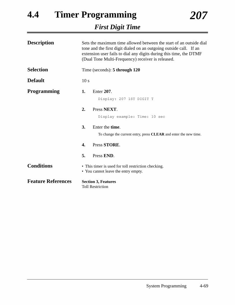
4.4 Timer ProgrammingFirst Digit Time
207
System Programming 4-69
Description Sets the maximum time allowed between the start of an outside dialtone and the first digit dialed on an outgoing outside call. If anextension user fails to dial any digits during this time, the DTMF(Dual Tone Multi-Frequency) receiver is released.
Selection Time (seconds): 5 through 120
Default 10 s
Programming 1. Enter 207.
Display: 207 1ST DIGIT T
2. Press NEXT.
Display example: Time: 10 sec
3. Enter the time.
To change the current entry, press CLEAR and enter the new time.
4. Press STORE.
5. Press END.
Conditions • This timer is used for toll restriction checking. • You cannot leave the entry empty.
Feature References Section 3, FeaturesToll Restriction

4.4 Timer ProgrammingInter Digit Time
208
4-70 System Programming
Description Assigns the maximum time allowed between digits on an outgoingtoll call. If an extension user fails to dial any digits during thistime, the DTMF (Dual Tone Multi-Frequency) receiver is released.This timer applies until the Toll Restriction check is completed.
Selection Time (seconds): 5 through 30
Default 10 s
Programming 1. Enter 208.
Display: 208 INTER DIGIT
2. Press NEXT.
Display example: Time:10 sec
3. Enter the time.
To change the current entry, press CLEAR and enter the new time.
4. Press STORE.
5. Press END.
Conditions • This timer is used for toll restriction checking. • You cannot leave the entry empty.
Feature References Section 3, FeaturesToll Restriction

4.4 Timer ProgrammingDial Start Time
211
System Programming 4-71
Description Sets the number of milliseconds the system waits before dialingafter an outside line is seized.
Selection Time (milliseconds): 0 through 40 (✕100 is the actual time)
Default 500 ms
Programming 1. Enter 211.
Display: 211 DIAL START
2. Press NEXT.
Display example: Time: 500 msec
3. Enter the time.
To change the current entry, press CLEAR and enter the new time.
4. Press STORE.
5. Press END.
Conditions • You enter a number from 0 through 40. The actual time is a 100 timesyour input.
• You cannot leave the entry empty.
Feature References Section 3, FeaturesLine Access, AutomaticLine Access, DirectLine Access, Individual

4.4 Timer ProgrammingCall Duration Count Start Time
212
4-72 System Programming
Description Sets the number of seconds the system waits between the end ofdialing and the start of the Station Message Detail Recording(SMDR) timer for outgoing toll calls. When the system has sentout all the digits to the central office and this timer expires, thesystem starts counting the call. A display telephone shows theelapsed time of the call. The starting time and the duration of a callare recorded in the SMDR record.
Selection Time (seconds): 0 through 60
Default 0 s
Programming 1. Enter 212.
Display: 212 CALL TIMER
2. Press NEXT.
Display example: Time: 0 sec
3. Enter the time.
To change the current entry, press CLEAR and enter the new time.
4. Press STORE.
5. Press END.
Conditions • The timer starts counting after all the digits are dialed. This timer doesnot apply to incoming calls. The timer for incoming calls startsimmediately.
• You cannot leave the entry empty.
Feature References Section 3, FeaturesDisplay, Call InformationStation Message Detail Recording (SMDR)

4.4 Timer ProgrammingDISA Delayed Answer Time
213
System Programming 4-73
Description Assigns the number of rings between a call received and the answerby the Direct Inward System Access (DISA) feature.
Selection Number of rings: 0 through 6
Default 1 ring
Programming 1. Enter 213.
Display: 213 DISA ANSWER
2. Press NEXT.
Display example: Time:1 rings
3. Enter the number of rings.
To change the current entry, enter the new number of rings.
4. Press STORE.
5. Press END.
Conditions • One ring is equivalent to five seconds.• You cannot leave the entry empty.
Feature References Section 3, FeaturesDirect Inward System Access (DISA)

4.4 Timer ProgrammingMessage Waiting Ring Interval Time
216
4-74 System Programming
Description Sets the Message Waiting ring interval time for a standardtelephone.
Selection Time (minutes): 0 through 64
Default 0 min (no ring)
Programming 1. Enter 216.
Display: 216 MW RING TIME
2. Press NEXT.
Display example: Interval: 0 min
3. Enter the time.
To change the current entry, press CLEAR and enter the new time.
4. Press STORE.
5. Press END.
Conditions • When the interval time is set to “0”, the telephone does not ring forMessage Waiting notification.
• Selecting the message waiting ring type, 3 quick rings or 2 normalrings, in program [990] “System Additional Information, Field (40)” isavailable. If you prefer soft ringing, select “3 quick rings”. In this case,there may be some kinds of telephones which do not ring.
Feature References Section 3, FeaturesMessage Waiting

4.4 Timer ProgrammingTimed Reminder Alarm Ring Time
217
System Programming 4-75
Description Sets the number of seconds the Timed Reminder alarm rings.
Selection Time (seconds): 30 through 240
Default 30 s
Programming 1. Enter 217.
Display: 217 TIMED REMIND
2. Press NEXT.
Display example: Reminder: 30sec
3. Enter the time.
To change the current entry, enter the new time.
4. Press STORE.
5. Press END.
Conditions None
Feature References Section 3, FeaturesTimed ReminderTimed Reminder, Remote (Wake-Up Call)

4.4 Timer ProgrammingDISA AA Wait Time
218
4-76 System Programming
Description Sets the number of seconds the system waits for a second digitentry. If the timer expires, the system assumes that the first digit isa DISA (Direct Inward System Access) built-in auto attendantnumber if assigned in program [815] “DISA Built-in AutoAttendant”.
Selection Time (seconds): 1 through 5
Default 1 sec
Programming 1. Enter 218.
Display: 218 DISA AA WAIT
2. Press NEXT.
Display example: Time:1 sec
3. Enter the time.
To change the current entry, enter the new time.
4. Press STORE.
5. Press END.
Conditions None
Feature References Section 3, FeaturesDirect Inward System Access (DISA)

4.4 Timer ProgrammingCall Park Recall Time
219
System Programming 4-77
Description Sets the number of rings before call park recall occurs. Call parkrecall is used to alert an extension that a call has been parked for anextended period of time.
Selection Number of rings: 0 through 48 (0=Call Park Recall disabled)
Default 12 rings
Programming 1. Enter 219.
Display: 219 PARK RECALL
2. Press NEXT.
Display example: Time:12 rings
3. Enter the number of rings.
To change the current entry, press CLEAR and enter the new numberof rings.
4. Press STORE.
5. Press END.
Conditions • One ring is equivalent to five seconds.• Select “0” if Call Park Recall is not required. • You cannot leave the entry empty.
Feature References Section 3, FeaturesCall Park

4.5 TRS / ARS ProgrammingTRS Override for System Speed Dialing
300
4-78 System Programming
Description Allows you to enable toll restriction override for System SpeedDial Numbers. If this is enabled, all extension users can makeSystem Speed Dialing calls with no restriction.
Selection Enable / Disable
Default Disable
Programming 1. Enter 300.
Display: 300 TRS SPEED DL
2. Press NEXT.
Display example: Override:Disable
3. Keep pressing SELECT until the desired selection isdisplayed.
4. Press STORE.
5. Press END.
Conditions Select “Enable” for toll restriction override; Select “Disable” for tollrestriction.
Feature References Section 3, FeaturesToll Restriction Override for System Speed Dialing
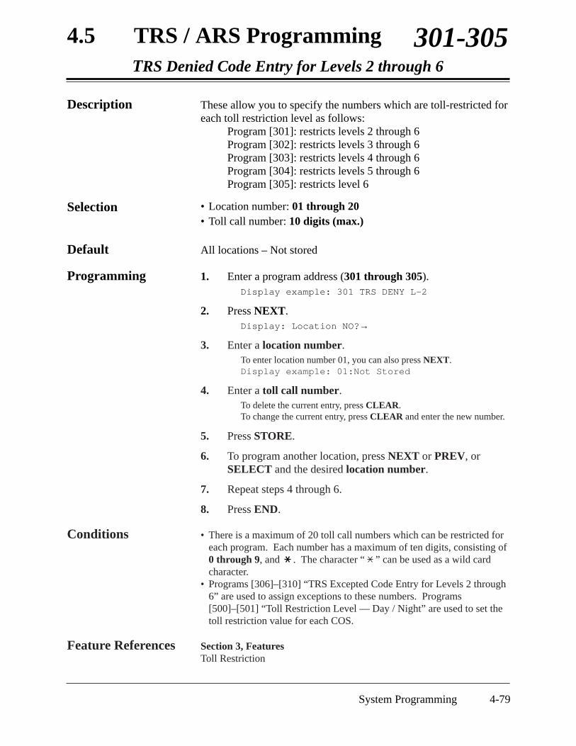
4.5 TRS / ARS ProgrammingTRS Denied Code Entry for Levels 2 through 6
301-305
System Programming 4-79
Description These allow you to specify the numbers which are toll-restricted foreach toll restriction level as follows:
Program [301]: restricts levels 2 through 6Program [302]: restricts levels 3 through 6Program [303]: restricts levels 4 through 6Program [304]: restricts levels 5 through 6Program [305]: restricts level 6
Selection • Location number: 01 through 20• Toll call number: 10 digits (max.)
Default All locations – Not stored
Programming 1. Enter a program address (301 through 305).Display example: 301 TRS DENY L–2
2. Press NEXT.Display: Location NO?→
3. Enter a location number.To enter location number 01, you can also press NEXT.Display example: 01:Not Stored
4. Enter a toll call number.To delete the current entry, press CLEAR.To change the current entry, press CLEAR and enter the new number.
5. Press STORE.
6. To program another location, press NEXT or PREV, orSELECT and the desired location number.
7. Repeat steps 4 through 6.
8. Press END.
Conditions • There is a maximum of 20 toll call numbers which can be restricted foreach program. Each number has a maximum of ten digits, consisting of0 through 9, and . The character “ ” can be used as a wild cardcharacter.
• Programs [306]–[310] “TRS Excepted Code Entry for Levels 2 through6” are used to assign exceptions to these numbers. Programs[500]–[501] “Toll Restriction Level — Day / Night” are used to set thetoll restriction value for each COS.
Feature References Section 3, FeaturesToll Restriction

4.5 TRS / ARS ProgrammingTRS Excepted Code Entry for Levels 2 through 6
306-310
4-80 System Programming
Description These allow you to assign numbers which are exceptions to the tollrestriction specified in programs [301] through [305] as follows:
Program [306]: applies to level 2 Program [307]: applies to levels 2 through 3Program [308]: applies to levels 2 through 4Program [309]: applies to levels 2 through 5Program [310]: applies to levels 2 through 6
Selection • Location number: 1 through 5• Exceptional number: 10 digits (max.)
Default All locations – Not stored
Programming 1. Enter a program address (306 through 310).Display example: 306 TRS ALLOW 2
2. Press NEXT.Display: Location NO?→
3. Enter a location number.To enter location number 1, you can also press NEXT.
Display example: 1:Not Stored
4. Enter an exceptional number.To delete the current entry, press CLEAR.To change the current entry, press CLEAR and enter the new number.
5. Press STORE.
6. To program another location, press NEXT or PREV, orSELECT and the desired location number.
7. Repeat steps 4 through 6.
8. Press END.
Conditions There is a maximum of five numbers for each program. Each number hasa maximum of ten digits, consisting of 0 through 9, and . Thecharacter “ ” can be used as a wild card character.
Note Store your emergency numbers in program [310].
Feature References Section 3, FeaturesToll Restriction

4.5 TRS / ARS ProgrammingSpecial Carrier Access Codes
311
System Programming 4-81
Description Assigns special carrier numbers. This allows the system torecognize the user-dialed special carrier number in order to insertthe required pause and apply toll restriction.
Selection • Location number: 01 through 20• Special carrier number: 7 digits (max.)
Default All locations – Not stored
Programming 1. Enter 311.
Display: 311 CARRIER #
2. Press NEXT.
Display: Location NO?→
3. Enter a location number.
To enter location number 01, you can also press NEXT.
Display example: 01:Not Stored
4. Enter a special carrier number.
To delete the current entry, press CLEAR.To change the current entry, press CLEAR and enter the new number.
5. Press STORE.
6. To program another location, press NEXT or PREV, orSELECT and the desired location number.
7. Repeat steps 4 through 6.
8. Press END.
Conditions There is a maximum of 20 special carrier numbers. Each carrier numberhas a maximum of seven digits, consisting of 0 through 9, , and #.You can also use the PAUSE button to enter a wild card character. It will be displayed as “X”.
Feature References Section 3, FeaturesPause Insertion, AutomaticToll Restriction for Special Carrier Access

4.5 TRS / ARS ProgrammingARS Mode
312
4-82 System Programming
Description Allows you to turn on or off the Automatic Route Selection (ARS)mode. ARS, if enabled, selects the least expensive route to be usedfor an outside call.
Selection On / Off
Default Off
Programming 1. Enter 312.
Display: 312 ARS MODE SET
2. Press NEXT.
Display example: ARS:Off
3. Press SELECT until the desired selection is displayed.
4. Press STORE.
5. Press END.
Conditions • If “Off” is selected, the Automatic Line Access feature functionsinstead of ARS.
• Programs [313] through [331] are used to program ARS.
Feature References Section 3, FeaturesAutomatic Route Selection (ARS)Line Access, Automatic

4.5 TRS / ARS ProgrammingARS Time
313
System Programming 4-83
Description Assigns times for the four Automatic Route Selection (ARS) timeschedules. It is possible to split a day into four time zones(maximum) so that the least expensive line is selected for that time.According to the service hours and charges offered by your carriers,enter the starting time of each zone.
Selection • Day of the week: 1 (Mon) / 2 (Tue) / 3 (Wed) / 4 (Thu) /5 (Fri) / 6 (Sat) / 7 (Sun) / (all days)
• Time schedule: A / B / C / D• Time (hour) : 1 through 12 / Disable (no schedule)• AM / PM
Default All days of the week : A – 8:00 AM; B – 5:00 PM; C – 9:00 PM;D – Disable
Programming 1. Enter 313.Display: 313 ARS TIME SET
2. Press NEXT.Display: Day of week?→
3. Enter the day of the week.Display example: MON-A: 8:00 AM
To program another time schedule, keep pressing NEXT or PREVuntil the desired time schedule is displayed.
4. Enter the hour.To set no schedule (Disable), press SELECT and go to step 7.
If “Disable” is selected, pressing SELECT shows the previous storedhour.
To change the current entry, press CLEAR and enter the new hour.
5. Press to select AM / PM.
6. Press SELECT for AM or PM.
7. Press STORE.
8. To program another time schedule, keep pressing NEXT orPREV until the desired time schedule is displayed.
9. Repeat steps 4 through 8.
10. Press END.

4.5 TRS / ARS ProgrammingARS Time (contd.)
313
4-84 System Programming
Conditions • Enter a starting time for each time schedule. Select “Disable” for idleschedules.
• You cannot leave an entry empty.• To assign all days of the week, press the key in step 3. In this case,
the display shows the contents programmed for Monday.
Feature References Section 3, FeaturesAutomatic Route Selection (ARS)

4.5 TRS / ARS ProgrammingARS Leading Digit Entry for Plans 1 through 8
314-321
System Programming 4-85
Description By entering numbers into each leading digit plan (programs below)you are starting the process to determine which outside line will beused to route the call. Program: [314] [315] [316] [317] [318] [319] [320] [321]Plan: 1 2 3 4 5 6 7 8 These eight plans are used to analyze the number which the userdials and decide the route plan for the call. If the user-dialednumber is registered in Plan 1, then Routing Plan 1 is selected forthe call. Automatic Route Selection (ARS) Leading Digit Entry forPlans 1 through 8 match ARS Routing Plans 1 through 8 (programs[322] through [329]) respectively.
Selection • Location number: 01 through 50• Leading digit number: 10 digits (max.)
Default All locations – Not stored
Programming 1. Enter a program address (314 through 321).
Display example: 314 ARS LEAD D-1
2. Press NEXT.
Display: Location NO?→
3. Enter a location number.
To enter location number 01, you can also press NEXT.
Display example: 01:Not Stored
4. Enter a leading digit number.
To delete the current entry, press CLEAR.
To change the current entry, press CLEAR and enter the new number.
5. Press STORE.
6. To program another location, press NEXT or PREV, orSELECT and the desired location number.
7. Repeat steps 4 through 6.
8. Press END.

4.5 TRS / ARS ProgrammingARS Leading Digit Entry for Plans 1 through 8 (contd.)
314-321
4-86 System Programming
Conditions Each number has a maximum of ten digits, consisting of 0 through 9, and. The character “ ” can be used as a wild card character (i.e., “do not
care” digit). The system scans all the ARS Leading Digit Planssimultaneously from left to right. The scan ends as soon as the dialednumber matches a table entry. When using a wild card character, it isimportant to use one in each digit position that must be scanned. Forexample, to differentiate local and long distance calls with the sameleading digits: Plan 1) 1- ; Plan 2) 1-215. Note that three wild carddigits were used to ensure that the system scanned the first four digits. Ashorter string of “ ”s would send all the calls to the Plan 1 carrier.
Feature References Section 3, FeaturesAutomatic Route Selection (ARS)

4.5 TRS / ARS ProgrammingARS Routing Plans 1 through 8
322-329
System Programming 4-87
Description Assigns the outside line and modification plan to be used foreach route plan and time schedule.Program: [322] [323] [324] [325] [326] [327] [328] [329]Plan: 1 2 3 4 5 6 7 8
Selection • Time schedule: A / B / C / D• Outside line number: 1 through 3• Modification table number: 1 through 8
Default All time schedules – Not stored
Programming 1. Enter a program address (322 through 329).Display example: 322 ARS ROUTE 1
2. Press NEXT to program time schedule A.To program another time schedule, keep pressing NEXT or PREVuntil the desired time schedule is displayed.
Display example: A:C M ,C M ,C M
3. Enter an outside line number.To delete the current entry, press CLEAR.
To change the current entry, enter the new number.
4. Press to enter the paired modification table number.
5. Enter a modification table number.To delete the current entry, press CLEAR.
To change the current entry, enter the new modification table number.
6. Press to enter the next priority outside line number.
7. Repeat steps 3 through 6 to enter other outside line numbersand modification table numbers.
8. Press STORE.
9. To program another time schedule, keep pressing NEXT orPREV until the desired time schedule is displayed.
10. Repeat steps 3 through 9.
11. Press END.

4.5 TRS / ARS ProgrammingARS Routing Plans 1 through 8 (contd.)
322-329
4-88 System Programming
Conditions • Up to three outside lines and modification plans can be assigned foreach time schedule. The outside line number and modification tablenumber must be entered together. The highest priority outside linenumber and modification table number is entered first (left to right).
• Programs [330] “ARS Modify Removed Digit” and [331] “ARSModify Added Number” are used to make up the eight ModificationTables.
Feature References Section 3, FeaturesAutomatic Route Selection (ARS)

4.5 TRS / ARS ProgrammingARS Modify Removed Digit
330
System Programming 4-89
Description Determines how the dialed number should be modified beforetransmitting to the central office. You can delete the digits from thebeginning of the dialed number.
Selection • Modification table number: 1 through 8• Number of digits to be deleted: 0 through 9 (0=no deletion)
Default All modification tables – 0
Programming 1. Enter 330.
Display: 330 ARS REMOVE
2. Press NEXT.
Display: Modify Table?→
3. Enter a modification table number.
To enter table number 1, you can also press NEXT.
Display example: 1:0
4. Enter the number of digits to be deleted.
To change the current entry, enter the new number.
5. Press STORE.
6. To program another modification table, press NEXT orPREV, or SELECT and the desired modification tablenumber.
7. Repeat steps 4 through 6.
8. Press END.
Conditions There is a maximum of eight Modification Tables. You can only delete 1digit of a number in each table.
Feature References Section 3, FeaturesAutomatic Route Selection (ARS)

4.5 TRS / ARS ProgrammingARS Modify Added Number
331
4-90 System Programming
Description Determines how the dialed number should be modified beforetransmitting to the central office. Assigned numbers are added tothe beginning of the dialed number.
Selection • Modification table number: 1 through 8• Number to be added: 20 digits (max.)
Default All modification tables – Not stored
Programming 1. Enter 331.
Display: 331 ARS ADD #'S
2. Press NEXT.
Display: Modify Table?→
3. Enter a modification table number.
To enter table number 1, you can also press NEXT.
Display example: 1:
4. Enter the number to be added.
To delete the current entry, press CLEAR.
To change the current entry, press CLEAR and enter the new number.
5. Press STORE.
6. To program another modification table, press NEXT orPREV, or SELECT and the desired modification tablenumber.
7. Repeat steps 4 through 6.
8. Press END.
Conditions • There is a maximum of eight Modification Tables, each of which can begiven a number to be added.
• Each number has a maximum of 20 digits, consisting of 0 through 9,, #, and PAUSE.
Feature References Section 3, FeaturesAutomatic Route Selection (ARS)

4.5 TRS / ARS ProgrammingExtra Entry Table Selection
332
System Programming 4-91
Description Selects the code table which enables an extra 100 entries withinDenied or Except Code Table.
Selection • Deny / Except• Level number: 2 through 6
Default Except - 2
Programming 1. Enter 332.
Display: 332 TRS EXTRA +
2. Press NEXT.
Display example: Table:Except-2
3. Keep pressing SELECT until the desired selection isdisplayed.
4. Press to enter a level number.
5. Enter a level number.
Display example: Table:Except-3
6. Press STORE.
7. Press END.
Conditions There is a maximum of either 120 toll call numbers for Denied CodeTable or a maximum of 105 toll call numbers for Excepted Code Table.
Feature References Section 3, FeaturesToll Restriction

4.5 TRS / ARS ProgrammingTRS Entry Code Assignment for Extra Table
333
4-92 System Programming
Description This program allows you to specify the numbers for extra Deniedor Excepted Code Table for expansion.
Selection • Location number: 001 through 100• Toll call number: 10 digits (max.)
Default All locations – Not stored
Programming 1. Enter 333.
Display: 333 TRS EXTRA -
2. Press NEXT.
Display: Location NO?→
3. Enter a location number.
To enter location number 001, you can also press NEXT.
Display example: 001:Not Stored
4. Enter a toll call number.
To delete the current entry, press CLEAR.
To change the current entry, press CLEAR and enter the new number.
5. Press STORE.
6. To program another location number, press NEXT or PREV,or SELECT and the desired location number.
7. Repeat steps 4 through 6.
8. Press END.
Conditions There is a maximum of either 120 toll call numbers for Denied CodeTable or a maximum of 105 toll call numbers for Excepted Code Table. Each number has a maximum of ten digits, consisting of 0 through 9, and
. The character “ ” can be used as a wild card character.
Feature References Section 3, FeaturesToll Restriction

4.5 TRS / ARS ProgrammingEmergency Dial Number Set
334
System Programming 4-93
Description Stores up to ten emergency call numbers.Emergency numbers are not subject to toll restriction, AccountCode – Verified mode and Electronic Station Lockout.
Selection • Location number: 01 through 10• Emergency number: 7 digits (max.)
Default Location 01 = 911, Other location = Not stored
Programming 1. Enter 334.
Display: 334 EMERGENCY #
2. Press NEXT.
Display: Location NO?→
3. Enter a location number.
To enter location number 01, you can also press NEXT.
Display example: 01:911
4. Enter an emergency number.
To delete the current entry, press CLEAR.To change the current entry, press CLEAR and enter the new number.
5. Press STORE.
6. To program another location, press NEXT or PREV, orSELECT and the desired location number.
7. Repeat steps 4 through 6.
8. Press END.
Conditions Each emergency number has a maximum of seven digits, consisting of 0through 9.
Feature References Section 3, FeaturesAutomatic Route Selection (ARS)Toll Restriction

4.6 Outside Line ProgrammingOutside Line Connection Assignment
400
4-94 System Programming
Description Used to identify the outside lines which are connected to thesystem. This prevents users from originating a call to a line whichis not connected.
Selection • Outside line (CO) number: 1 through 3, ( =all outside lines)• Connect / No Connect
Default All outside lines – Connect
Programming 1. Enter 400.
Display: 400 CO CONNECT
2. Press NEXT.
Display: CO Line NO?→
3. Enter an outside line number.
To enter outside line number 1, you can also press NEXT.
Display example: CO1:Connect
4. Keep pressing SELECT until the desired selection isdisplayed.
5. Press STORE.
6. To program another outside line, press NEXT or PREV, orSELECT and the desired outside line number.
7. Repeat steps 4 through 6.
8. Press END.
Conditions • To assign all outside lines to one selection, press the key in step 3.In this case, the display shows the contents programmed for outside line1.
Feature References Section 3, FeaturesOutside Line Connection Assignment

4.6 Outside Line ProgrammingDial Mode Selection
402
System Programming 4-95
Description Each outside line can be programmed for DTMF (Dual Tone Multi-Frequency), pulse (rotary) or call blocking. This program assignsyour choice to each line.
DTMF: The dialing signals from an extension, either tone or pulse, areconverted to tone signals and transmitted to the outside line.
Pulse: The dialing signals from an extension, either tone or pulse, areconverted to pulse signals and transmitted to the outside line.
Call blocking: If your central office can receive both DTMF and pulse signals butyou are contracted for pulse, select this mode. When dialing on theline with a touch tone telephone, only the pulse signals are sent tothe outside line.
Selection • Outside line (CO) number: 1 through 3, ( =all outside lines)• DTMF / Pulse / C. Block (call blocking)
Default All outside lines – DTMF
Programming 1. Enter 402.
Display: 402 DIAL MODE
2. Press NEXT.
Display: CO Line NO?→
3. Enter an outside line number.
To enter outside line number 1, you can also press NEXT.
Display example: CO1:DTMF
4. Keep pressing SELECT until the desired selection isdisplayed.
5. Press STORE.
6. To program another outside line, press NEXT or PREV, orSELECT and the desired outside line number.
7. Repeat steps 4 through 6.
8. Press END.

4.6 Outside Line ProgrammingDial Mode Selection (contd.)
402
4-96 System Programming
Conditions • To assign all lines to one selection, press the key in step 3. In thiscase, the display shows the contents programmed for outside line 1.
• If DTMF is assigned, set the DTMF time of the line in program [404]“DTMF Time”.
• If pulse or call blocking is assigned, set the pulse speed of the line inprogram [403] “Pulse Speed Selection”, and set the pulse break ratioand inter-digit pause in program [990] “System Additional Information,Field (17)” and in “Field (21)”, if necessary.
Feature References Section 3, FeaturesDial Type Selection

4.6 Outside Line ProgrammingPulse Speed Selection
403
System Programming 4-97
Description An outside line set for pulse or call blocking mode in program[402] “Dial Mode Selection” can have two pulse rates, 10 pps (low)and 20 pps (high). This program sets the pulse speed for eachoutside line set to pulse or call blocking mode.
Selection • Outside line (CO) number: 1 through 3, ( =all outside lines)• 10 pps / 20 pps
Default All outside lines – 10 pps
Programming 1. Enter 403.Display: 403 PULSE SPEED
2. Press NEXT.Display: CO Line NO?→
3. Enter an outside line number.To enter outside line number 1, you can also press NEXT.
Display example: CO1:10pps
4. Keep pressing SELECT until the desired selection isdisplayed.
5. Press STORE.
6. To program another outside line, press NEXT or PREV, orSELECT and the desired outside line number.
7. Repeat steps 4 through 6.
8. Press END.
Conditions • To assign all outside lines to one selection, press the key in step 3.In this case, the display shows the contents programmed for outside line1.
• The pulse speed required is determined by the outside or PBX line.• Program [990] “System Additional Information, Field (17) and Field
(21)” are used to select a pulse break ratio and inter-digit pause, ifneeded.
Feature References Section 3, FeaturesDial Type Selection

4.6 Outside Line ProgrammingDTMF Time
404
4-98 System Programming
Description An outside line set to DTMF (Dual Tone Multi-Frequency) mode inprogram [402] “Dial Mode Selection” can have two settings. Thisprogram sets the duration of the DTMF signals sent to an outsideline to DTMF mode.
Selection • Outside line (CO) number: 1 through 3, ( =all outside lines)• Time (milliseconds): 80 / 160
Default All outside lines – 80 ms
Programming 1. Enter 404.
Display: 404 DTMF TIME
2. Press NEXT.
Display: CO Line NO?→
3. Enter an outside line number.
To enter outside line number 1, you can also press NEXT.
Display example: CO1: 80msec
4. Keep pressing SELECT until the desired selection isdisplayed.
5. Press STORE.
6. To program another outside line, press NEXT or PREV, orSELECT and the desired outside line number.
7. Repeat steps 4 through 6.
8. Press END.
Conditions • To assign all outside lines to one selection, press the key in step 3.In this case, the display shows the contents programmed for outside line1.
• The DTMF time required is determined by the outside line or PBX line.
Feature References Section 3, FeaturesDial Type Selection

4.6 Outside Line ProgrammingCPC Signal Detection Incoming Set
405
System Programming 4-99
Description Assigns the expected minimum duration of the Calling PartyControl (CPC) Signal on incoming outside calls. If this isprogrammed, the system disconnects the line when the CPC Signalis detected.
Selection • Outside line (CO) number: 1 through 3, ( =all outside lines)• Time (milliseconds): Disable (no detection) / 100 / 200 / 300 /
400 / 500 / 600
Default All outside lines – 400 ms
Programming 1. Enter 405.
Display: 405 CPC INCOMING
2. Press NEXT.
Display: CO Line NO?→
3. Enter an outside line number.
To enter outside line number 1, you can also press NEXT.
Display example: CO1:400msec
4. Keep pressing SELECT until the desired time is displayed.
5. Press STORE.
6. To program another outside line, press NEXT or PREV, orSELECT and the desired outside line number.
7. Repeat steps 4 through 6.
8. Press END.
Conditions • To assign all outside lines to one selection, press the key in step 3.In this case, the display shows the contents programmed for outside line1.
• You may disable CPC Signal Detection for an outside line.• Program [415] “CPC Signal Detection Outgoing Set” is used to
program CPC Signal Detection for outgoing outside calls.
Feature References Section 3, FeaturesCalling Party Control (CPC) Signal DetectionDirect Inward System Access (DISA)

4.6 Outside Line ProgrammingCaller ID Assignment
406
4-100 System Programming
Description Enables the Caller ID feature for the outside lines to which a CallerID Service is offered by a Central Office by contract.
Selection • Outside line (CO) number: 1 through 3, ( =all outside lines)• Enable / Disable
Default All outside lines – Disable
Programming 1. Enter 406.
Display: 406 CALLER ID CO
2. Press NEXT.
Display: CO Line NO?→
3. Enter an outside line number.
To enter outside line number 1, you can also press NEXT.
Display example: CO1:Disable
4. Keep pressing SELECT until the desired selection isdisplayed.
5. Press STORE.
6. To program another outside line, press NEXT or PREV, orSELECT and the desired outside line number.
7. Repeat steps 4 through 6.
8. Press END.
Conditions • To assign all outside lines to one selection, press the key in step 3.In this case, the display shows the contents programmed for outside line1.
• The following programs are used to program Caller ID feature: [110]“Caller ID Code Set” and [111] “Caller ID Name Set”.
Feature References Section 3, FeaturesCaller ID

4.6 Outside Line ProgrammingDIL 1:1 Extension — Day / Night
407-408
System Programming 4-101
Description The Direct In Lines (DIL) 1:1 feature allows incoming outside callsto be directed to a specific extension. When an outside line isassigned as DIL 1:1, it is necessary to assign the destination. Theseprograms specify the extension number for day or night mode.
Selection • Outside line (CO) number: 1 through 3, ( =all outside lines)• Extension number: 2 through 4 digits / Disable (no DIL 1:1)
Default All outside lines – Disable — Day / Night
Programming 1. Enter a program address (407 for day or 408 for night).Display example: 407 DIL 1:1 DAY
2. Press NEXT.Display: CO Line NO?→
3. Enter an outside line number.To enter outside line number 1, you can also press NEXT.
Display example: CO1:Disable
4. Enter an extension number.To change the current entry, press CLEAR and enter the new number.
To disable DIL 1:1, press CLEAR.
5. Press STORE.
6. To program another outside line, press NEXT or PREV, orSELECT and the desired outside line number.
7. Repeat steps 4 through 6.
8. Press END.
Conditions • To assign all outside lines to one selection, press the key in step 3. Inthis case, the display shows the contents programmed for outside line 1.
• You set the extension numbers in program [003] “Extension NumberSet”, voice mail extension numbers in program [118] “Voice MailExtension Number Assignment”, phantom extension numbers in program[124] “Phantom Extension Number Assignment” or floating numbers ofpager(s), DISA (Direct Inward System Access) message(s) and extensiongroup(s) in program [813] “Floating Number Assignment”.
• If an outside line is also programmed for DIL 1:N in programs[603]–[604] “DIL 1:N Extension and Delayed Ringing — Day / Night”,it is regarded as a DIL 1:1 line.
Feature References Section 3, FeaturesDirect In Lines (DIL) Night ServiceDirect Inward System Access (DISA)

4.6 Outside Line ProgrammingIntercept Extension — Day / Night
409-410
4-102 System Programming
Description Intercept Routing provides an automatic re-direction of calls whichcannot or have not been answered (IRNA: Intercept Routing – NoAnswer). These programs set the destination in both day and nightmodes for each outside line.
Selection • Outside line (CO) number: 1 through 3, ( =all outside lines)• Extension number: 2 through 4 digits / Disable (no Intercept
Routing)
Default All outside lines – Disable — Day / Night
Programming 1. Enter a program address (409 for day or 410 for night).Display example: 409 INTERCEP DAY
2. Press NEXT.Display: CO Line NO?→
3. Enter the outside line number.To enter outside line number 1, you can also press NEXT.
Display example: CO1:Disable
4. Enter an extension number.To change the current entry, press CLEAR and enter the new number.
To disable Intercept Routing, press CLEAR.
5. Press STORE.
6. To program another outside line, press NEXT or PREV, orSELECT and the desired outside line number.
7. Repeat steps 4 through 6.
8. Press END.
Conditions • You set the extension numbers in program [003] “Extension NumberSet”, voice mail extension numbers in program [118] “Voice MailExtension Number Assignment”, phantom extensions in program [124]“Phantom Extension Number Assignment” or floating numbers ofpager(s), DISA (Direct Inward System Access) message(s) andextension group(s) in program [813] “Floating Number Assignment”.
• To assign all outside lines to one selection, press the key in step 3.In this case, the display shows the contents programmed for outside line1.
Feature References Section 3, FeaturesIntercept Routing

4.6 Outside Line ProgrammingHost PBX Access Codes
411
System Programming 4-103
Description Assigns Host PBX or Centrex access codes. If the system isinstalled behind a host PBX or a Centrex system, an access code isrequired to make an outside / Centrex call or to access Centrexfeatures. Up to four codes can be stored for an outside lineassigned to the line.
Selection • Outside line (CO) number: 1 through 3, ( =all outside lines)• Access code: 1 or 2 digits, four different entries (max.)
Default All outside lines – Not stored
Programming 1. Enter 411.
Display: 411 HOST PBX #’S
2. Press NEXT.
Display: CO Line NO?→
3. Enter an outside line number.
To enter outside line number 1, you can also press NEXT.
Display example: CO1: , , ,
4. Enter an access code.
To delete the current entry, press CLEAR.
To change the current entry, press CLEAR and enter the new access code.
Display example: CO1:01, , ,
5. To enter more access codes for the same outside line, pressand enter the access codes until all the required entries
are completed.
Display example: CO1:01,08,10,22
6. Press STORE.
7. To program another outside line, press NEXT or PREV, orSELECT and the desired outside line number.
8. Repeat steps 4 through 7.
9. Press END.

4.6 Outside Line ProgrammingHost PBX Access Codes (contd.)
411
4-104 System Programming
Conditions • This program is only required if a host PBX or Centrex line isconnected to the system.
• There is a maximum of four access codes per outside line. Each codehas one or two digits, consisting of 0 through 9, and .
• If conflicting access codes (such as 8 and 81) are stored for the sameoutside line, the 1-digit code (8) only will be in effect.
• When the programmed codes are dialed, Automatic Pause Insertion andToll Restriction are applied to the calls. The programmed pause time(in program [412] “Pause Time”) is automatically inserted after theaccess code.
• To assign all outside lines to one selection, press the key in step 3.In this case, the display shows the contents programmed for outside line1.
Feature References Section 3, FeaturesExternal Feature Access Pause Insertion, AutomaticHost PBX Access

4.6 Outside Line ProgrammingPause Time
412
System Programming 4-105
Description Assigns the length of the pause time. The programmed pause timeis automatically inserted after a line access code or a host PBXaccess code programmed in [411] “Host PBX Access Codes” ormanually inserted if the PAUSE button is pressed by the user.
Selection • Outside line (CO) number: 1 through 3, ( =all outside lines)• Time (seconds): 1.5 / 2.5 / 3.5 / 4.5
Default All outside lines – 1.5 s
Programming 1. Enter 412.
Display: 412 PAUSE TIME
2. Press NEXT.
Display: CO Line NO?→
3. Enter an outside line number.
To enter outside line number 1, you can also press NEXT.
Display example: CO1:1.5sec
4. Keep pressing SELECT until the desired time is displayed.
5. Press STORE.
6. To program another outside line, press NEXT or PREV, orSELECT and the desired outside line number.
7. Repeat steps 4 through 6.
8. Press END.
Conditions • To assign all outside lines to one selection, press the key in step 3.In this case, the display shows the contents programmed for outside line1.
Feature References Section 3, FeaturesHost PBX Access Pause Insertion, Automatic

4.6 Outside Line ProgrammingFlash Time
413
4-106 System Programming
Description Assigns the length of the flash time. If your system is installedbehind a host PBX or Centrex line, External Feature Access (EFA)is necessary to obtain their services. To enable it, select a requiredhooking signal sending time for the outside line.
Selection • Outside line (CO) number: 1 through 3, ( =all outside lines)• Time (milliseconds): Disable (no EFA) / 80 / 96 / 112 / 200 / 300 /
400 / 500 / 600 / 700 / 800 / 900 / 1000 /1100 / 1200
Default All outside lines – 600 ms
Programming 1. Enter 413.Display: 413 FLASH TIME
2. Press NEXT.Display: CO Line NO?→
3. Enter an outside line number.To enter outside line number 1, you can also press NEXT.
Display example: CO1: 600msec
4. Keep pressing SELECT until the desired time is displayed.
5. Press STORE.
6. To program another outside line, press NEXT or PREV, orSELECT and the desired outside line number.
7. Repeat steps 4 through 6.
8. Press END.
Conditions • You may disable EFA, if not required. The Flash feature will be ineffect in place of EFA. Program [414] “Disconnect Time” is used toselect the time required for the Flash feature.
• The flash time required is determined by the central office or the hostPBX lines.
• To assign all outside lines to one selection, press the key in step 3.In this case, the display shows the contents programmed for outside line1.
Feature References Section 3, FeaturesExternal Feature Access

4.6 Outside Line ProgrammingDisconnect Time
414
System Programming 4-107
Description Determines the amount of time between successive accesses to thesame outside line.
Selection • Outside line (CO) number: 1 through 3, ( =all outside lines)• Time (seconds): 1.5 / 4.0
Default All outside lines – 1.5 s
Programming 1. Enter 414.
Display: 414 DISCONNECT
2. Press NEXT.
Display: CO Line NO?→
3. Enter an outside line number.
To program outside line number 1, you can also press NEXT.
Display example: CO1:1.5sec
4. Keep pressing SELECT until the desired time is displayed.
5. Press STORE.
6. To program another outside line, press NEXT or PREV, orSELECT and the desired outside line number.
7. Repeat steps 4 through 6.
8. Press END.
Conditions • The disconnect time must be longer than the requirements of the centraloffice or the host PBX.
• To assign all outside lines to one selection, press the key in step 3.In this case, the display shows the contents programmed for outside line1.
Feature References Section 3, FeaturesFlash

4.6 Outside Line ProgrammingCPC Signal Detection Outgoing Set
415
4-108 System Programming
Description Enables or disables Calling Party Control (CPC) Signal Detectionduring the time between the originated outside call and theestablished outside call. If this is enabled, the system disconnectsthe line with the time set in program [405] “CPC Signal DetectionIncoming Set” when the CPC Signal is detected.
Selection • Outside line (CO) number: 1 through 3, ( =all outside lines)• Enable (detection) / Disable (no detection)
Default Disable
Programming 1. Enter 415.Display: 415 CPC OUTGOING
2. Press NEXT.Display: CO Line NO?→
3. Enter an outside line number.To enter outside line number 1, you can also press NEXT.
Display example: CO1:Disable
4. Keep pressing SELECT until the desired selection isdisplayed.
5. Press STORE.
6. To program another outside line, press NEXT or PREV, orSELECT and the desired outside line number.
7. Repeat steps 4 through 6.
8. Press END.
Conditions • Some central offices (CO) may send CPC-like signals during the dialingsequence and an attempt to make a call may be terminated. If your COis such a type, select “Disable”.
• Program [405] “CPC Signal Detection Incoming Set” is used to setCPC Signal Detection Time.
• To assign all outside lines to one selection, press the key in step 3. Inthis case, the display shows the contents programmed for outside line 1.
Feature References Section 3, FeaturesCalling Party Control (CPC) Signal DetectionDirect Inward System Access (DISA)

4.6 Outside Line ProgrammingReverse Circuit Assignment
416
System Programming 4-109
Description Enables or disables Reverse Circuit detection.
Selection • Outside line (CO) number: 1 through 3, ( =all outside lines)• Regular (no detection) / Reverse (detection)
Default Regular
Programming 1. Enter 416.
Display: 416 REV. CURRENT
2. Press NEXT.
Display: CO Line NO?→
3. Enter an outside line number.
To enter outside line number 1, you can also press NEXT.
Display example: CO1:Regular
4. Keep pressing SELECT until the desired selection isdisplayed.
5. Press STORE.
6. To program another outside line, press NEXT or PREV, orSELECT and the desired outside line number.
7. Repeat steps 4 through 6.
8. Press END.
Conditions • To assign all outside lines to one selection, press the key in step 3.In this case, the display shows the contents programmed for outside line1.
Feature References Section 3, FeaturesReverse Circuit

4.6 Outside Line ProgrammingOutside Line Name Assignment
417
4-110 System Programming
Description Assigns names of the company or customer to each outside line so thatthe operator or extension user can find the destination which the calleris trying to reach before answering. If Caller ID is assigned, eachextension can select either the initial display, Caller ID or line name.
Selection • Outside line (CO) number: 1 through 3, ( =all outside lines)• Name: 10 characters (max.)
Default All outside lines – Not stored
Programming 1. Enter 417.Display: 417 CO LINE NAME
2. Press NEXT.Display: CO Line NO?→
3. Enter an outside line number.To enter outside line number 1, you can also press NEXT.
Display example: CO1:Not Stored
4. Enter a name.For entering characters, see Section 4.1.3 “Entering Characters”.
To delete the current entry, press CLEAR.
To change the current entry, press CLEAR and enter the new name.
5. Press STORE.
6. To program another outside line, press NEXT or PREV, orSELECT and the desired outside line number.
7. Repeat steps 4 through 6.
8. Press END.
Conditions • There is a maximum of 24 names. Each name has a maximum of 10characters.
• To assign all outside lines to one selection, press the key in step 3. Inthis case, the display shows the contents programmed for outside line 1.
• You can select the initial display, Caller ID or outside line name, byStation Programming.
Feature References Section 3, FeaturesDisplay, Call Information

4.7 COS ProgrammingToll Restriction Level — Day / Night
500-501
System Programming 4-111
Description Each extension must be assigned a Class of Service (COS). Theseprograms set the toll restriction value for each COS in day or nightmode.
Selection • COS number: 1 through 8, ( =all COS)• Level number: 1 through 8
Default COS 1 through 7 – Level 1 — Day / Night;COS 8 – Level 7 — Day / Night
Programming 1. Enter a program address (500 for day or 501 for night).
Display example: 500 TRS DAY LVL
2. Press NEXT.
Display: COS NO?→
3. Enter a COS number.
To enter COS number 1, you can also press NEXT.
Display example: COS1:1
4. Enter a level number.
To change the current entry, press CLEAR and enter the new number.
5. Press STORE.
6. To program another COS, press NEXT or PREV, orSELECT and the desired COS number.
7. Repeat steps 4 through 6.
8. Press END.
Conditions • To assign all COS to one selection, press the key in step 3. In thiscase, the display shows the contents programmed for COS 1.
• Program [601] “Class of Service” is used to assign a Class of Service toeach extension.
Feature References Section 3, FeaturesNight Service Toll Restriction

4.7 COS ProgrammingExtension-to-Outside Line Call Duration Limit
502
4-112 System Programming
Description This program allows you to restrict the duration of outside calls ona Class of Service (COS) basis.
Selection • COS number: 1 through 8, ( =all COS) • Disable (no limit) / Enable (limit)
Default All COS – Disable
Programming 1. Enter 502.Display: 502 EXT-CO TIMER
2. Press NEXT.Display: COS NO?→
3. Enter a COS number.To enter COS number 1, you can also press NEXT.
Display example: COS1:Disable
4. Keep pressing SELECT until the desired selection isdisplayed.
5. Press STORE.
6. To program another COS, press NEXT or PREV, orSELECT and the desired COS number.
7. Repeat steps 4 through 6.
8. Press END.
Conditions • An outside call originated or answered by the programmed extensionuser is disconnected when the time specified in program [205]“Extension-to-Outside Line Call Duration Time” expires.
• Extensions in limited classes cannot establish an outside-to-outside call,that is, cannot transfer / forward an outside call to another CO line orperform an Unattended Conference.
• To assign all COS to one selection, press the key in step 3. In thiscase, the display shows the contents programmed for COS 1.
• Program [601] “Class of Service” is used to assign a Class of Service toeach extension.
• Program [990] “System Additional Information, Field (12)” is used toprogram Limited Call Duration to be done for outgoing calls only.
Feature References Section 3, FeaturesCall Forwarding – to Outside Line Conference, UnattendedCall Transfer, Screened – to Outside Line Limited Call Duration

4.7 COS ProgrammingCall Transfer to Outside Line
503
System Programming 4-113
Description This program determines which Classes of Services (COS) areallowed to perform the Call Transfer to Outside Line function.
Selection • COS number: 1 through 8, ( =all COS)• Enable / Disable
Default All COS – Disable
Programming 1. Enter 503.
Display: 503 CALL XFER CO
2. Press NEXT.
Display: COS NO?→
3. Enter a COS number.
To enter COS number 1, you can also press NEXT.
Display example: COS1:Disable
4. Keep pressing SELECT until the desired selection isdisplayed.
5. Press STORE.
6. To program another COS, press NEXT or PREV, orSELECT and the desired COS number.
7. Repeat steps 4 through 6.
8. Press END.
Conditions • To assign all COS to one selection, press the key in step 3. In thiscase, the display shows the contents programmed for COS 1.
• Program [601] “Class of Service” is used to assign a Class of Service toeach extension.
Feature References Section 3, FeaturesCall Transfer, Screened – to Outside Line

4.7 COS ProgrammingCall Forwarding to Outside Line
504
4-114 System Programming
Description This program determines which Classes of Services (COS) areallowed to perform the Call Forwarding to Outside Line function.
Selection • COS number: 1 through 8, ( =all COS)• Disable / Enable
Default All COS – Disable
Programming 1. Enter 504.
Display: 504 CALL FWD CO
2. Press NEXT.
Display: COS NO?→
3. Enter a COS number.
To enter COS number 1, you can also press NEXT.
Display example: COS1:Disable
4. Keep pressing SELECT until the desired selection isdisplayed.
5. Press STORE.
6. To program another COS, press NEXT or PREV, orSELECT and the desired COS number.
7. Repeat steps 4 through 6.
8. Press END.
Conditions • To assign all COS to one selection, press the key in step 3. In thiscase, the display shows the contents programmed for COS 1.
• Program [601] “Class of Service” is used to assign a Class of Service toeach extension.
Feature References Section 3, FeaturesCall Forwarding – to Outside Line

4.7 COS ProgrammingExecutive Busy Override
505
System Programming 4-115
Description Determines which Classes of Services (COS) are allowed toperform Executive Busy Override – Extension / Outside Line.Executive Busy Override allows the user to interrupt an establishedcall.
Selection • COS number: 1 through 8, ( =all COS)• Disable / Enable
Default All COS – Disable
Programming 1. Enter 505.
Display: 505 EXEC BSY OR
2. Press NEXT.
Display: COS NO?→
3. Enter a COS number.
To enter COS number 1, you can also press NEXT.
Display example: COS1:Disable
4. Keep pressing SELECT until the desired selection isdisplayed.
5. Press STORE.
6. To program another COS, press NEXT or PREV, orSELECT and the desired COS number.
7. Repeat steps 4 through 6.
8. Press END.
Conditions • To assign all COS to one selection, press the key in step 3. In thiscase, the display shows the contents programmed for COS 1.
• Program [601] “Class of Service” is used to assign a Class of Service toeach extension.
Feature References Section 3, FeaturesExecutive Busy Override – ExtensionExecutive Busy Override – Outside Line

4.7 COS ProgrammingExecutive Busy Override Deny
506
4-116 System Programming
Description This program is used to determine which Classes of Services (COS)are allowed to deny Executive Busy Override. Executive BusyOverride Deny allows the user to prevent Executive Busy Override– Extension / Outside Line from being executed by anotherextension user.
Selection • COS number: 1 through 8, ( =all COS)• Disable / Enable
Default All COS – Enable
Programming 1. Enter 506.Display: 506 EXEC BSY DNY
2. Press NEXT.Display: COS NO?→
3. Enter a COS number.To enter COS number 1, you can also press NEXT.
Display example: COS1:Enable
4. Keep pressing SELECT until the desired selection isdisplayed.
5. Press STORE.
6. To program another COS, press NEXT or PREV, orSELECT and the desired COS number.
7. Repeat steps 4 through 6.
8. Press END.
Conditions • To assign all COS to one selection, press the key in step 3. In thiscase, the display shows the contents programmed for COS 1.
• Program [601] “Class of Service” is used to assign a Class of Service toeach extension.
Feature References Section 3, FeaturesExecutive Busy Override – ExtensionExecutive Busy Override – Outside Line

4.7 COS ProgrammingDo Not Disturb Override
507
System Programming 4-117
Description This program determines which Classes of Services (COS) areallowed to perform Do Not Disturb (DND) Override.
Selection • COS number: 1 through 8, ( =all COS)• Disable / Enable
Default All COS – Disable
Programming 1. Enter 507.
Display: 507 DND OVERRIDE
2. Press NEXT.
Display: COS NO?→
3. Enter a COS number.
To enter COS number 1, you can also press NEXT.
Display example: COS1:Disable
4. Keep pressing SELECT until the desired selection isdisplayed.
5. Press STORE.
6. To program another COS, press NEXT or PREV, orSELECT and the desired COS number.
7. Repeat steps 4 through 6.
8. Press END.
Conditions • To assign all COS to one selection, press the key in step 3. In thiscase, the display shows the contents programmed for COS 1.
• Program [601] “Class of Service” is used to assign a Class of Service toeach extension.
Feature References Section 3, FeaturesDo Not Disturb (DND) Override

4.7 COS ProgrammingAccount Code Entry Mode
508
4-118 System Programming
Description There are three account code modes: Option, Verified-All Calls andVerified-Toll Restriction Override. This program determines themode to be used by each Class of Service (COS).
Option mode: The user can enter any account code, if needed.Verified – All Calls mode:
The user must always enter a pre-assigned account code to make anoutside call.
Verified – Toll Restriction Override mode:The user must enter a pre-assigned account code when the userneeds to override toll restriction.
Selection • COS number: 1 through 8, ( =all COS)• Option / Verify – All (Verified-All Calls) /
Verify – Toll (Verified-Toll Restriction Override)
Default All COS – Option
Programming 1. Enter 508.Display: 508 ACC CODE OPT
2. Press NEXT.Display: COS NO?→
3. Enter a COS number.To enter COS number 1, you can also press NEXT.Display example: COS1:Option
4. Keep pressing SELECT until the desired selection isdisplayed.
5. Press STORE.
6. To program another COS, press NEXT or PREV, orSELECT and the desired COS number.
7. Repeat steps 4 through 6.
8. Press END.
Conditions • To assign all COS to one selection, press the key in step 3. In thiscase, the display shows the contents programmed for COS 1.
• Program [105] “Account Codes” is used to define the Account Codesfor the Verified modes.
• Program [601] “Class of Service” is used to assign a Class of Service toeach extension.
Feature References Section 3, FeaturesAccount Code EntryToll Restriction Override by Account Code Entry

4.7 COS ProgrammingOff-Hook Call Announcement (OHCA)
509
System Programming 4-119
Description Enables or disables to perform the Off-Hook Call Announcement(OHCA) on a Class of Service (COS) basis.
Selection • COS number: 1 through 8, ( =all COS)• Enable / Disable
Default All COS – Enable
Programming 1. Enter 509.
Display: 509 OHCA
2. Press NEXT.
Display: COS NO?→
3. Enter a COS number.
To enter COS number 1, you can also press NEXT.
Display example: COS1:Enable
4. Keep pressing SELECT until the desired selection isdisplayed.
5. Press STORE.
6. To program another COS, press NEXT or PREV, orSELECT and the desired COS number.
7. Repeat steps 4 through 6.
8. Press END.
Conditions • To assign all COS to one selection, press the key in step 3. In thiscase, the display shows the contents programmed for COS 1.
• Program [601] “Class of Service” is used to assign a Class of Service toeach extension.
Feature References Section 3, FeaturesOff-hook Call Announcement (OHCA)Whisper OHCA

4.8 Extension ProgrammingEXtra Device Port
600
4-120 System Programming
Description EXtra Device Port (XDP) allows a standard telephone to beconnected to the same jack as a digital proprietary telephone(DPT). This program assigns which jacks are XDP. The standardtelephone and DPT of the programmed jack work as independentextensions.
Selection • Jack number: 1 through 8, ( =all jacks)
• Disable / Enable
Default All jacks – Disable
Programming 1. Enter 600.
Display: 600 XDP PORT
2. Press NEXT.
Display: Jack NO?→
3. Enter a jack number.
To enter jack number 1, you can also press NEXT.
Display example: #1:Disable
4. Keep pressing SELECT until the desired selection isdisplayed.
5. Press STORE.
6. To program another jack, press NEXT or PREV, orSELECT and the desired jack number.
7. Repeat steps 4 through 6.
8. Press END.
Conditions • To assign all jacks to one selection, press the key in step 3. In thiscase, the display shows the contents programmed for Jack 1.
• Immediately after changing your assignment, the changed setting maynot work for a maximum of eight seconds.
Feature References Section 3, FeaturesEXtra Device Port (XDP)

4.8 Extension ProgrammingClass of Service
601
System Programming 4-121
Description Programs each extension for Class of Service (COS). The COSdetermines the call handling abilities of each extension.
Selection • Jack number: 1 through 8, (-1 / -2),( =all jacks, -1 = first part, -2 = second part)
• COS number: 1 through 8
Default All jacks-1/2 – COS 1
Programming 1. Enter 601.
Display: 601 COS #
2. Press NEXT.
Display: Jack NO?→
3. Enter a jack number.
To enter jack number 1, you can also press NEXT.
To select the second part (-2), press NEXT after entering a jack number.
Display example: #1-1:COS1
4. Enter a COS number.
To change the current entry, enter the new number.
5. Press STORE.
6. To program another jack, press NEXT or PREV, orSELECT and the desired jack number.
7. Repeat steps 4 through 6.
8. Press END.
Conditions • There is a maximum of eight Classes of Service. Every extensionmust be assigned to a Class of Service and is subject to the COSProgramming of programs [500] through [509] and [991].
• For an explanation of jack numbering, see “Rotation of jack number”on page 4-7.
• To assign all jacks to one COS, press the key in step 3. In thiscase, the display shows the contents programmed for Jack 1.
Feature References Section 3, Features
Class of Service (COS)

4.8 Extension ProgrammingExtension Group Assignment
602
4-122 System Programming
Description Assigns each extension to an extension group. Extension groupsare used for Group Call Pickup, Station Hunting, and Paging –Group.
Selection • Jack number: 1 through 8, (-1 / -2),( =all jacks, -1 = first part, -2 = second part)
• Extension group number: 1 through 8
Default All jacks-1/2 – Extension group 1
Programming 1. Enter 602.Display: 602 EXT GROUP #
2. Press NEXT.Display: Jack NO?→
3. Enter a jack number.To enter jack number 1, you can also press NEXT.
To select the second part (-2), press NEXT after entering the jacknumber.
Display example: #1-1:EXG1
4. Enter the extension group number.To change the current entry, enter the new extension group number.
5. Press STORE.
6. To program another jack, press NEXT or PREV, orSELECT and the desired jack number.
7. Repeat steps 4 through 6.
8. Press END.
Conditions • There is a maximum of eight extension groups. Each extension canonly belong to one group.
• For an explanation of jack numbering, see “Rotation of jack number”on page 4-7.
• To assign all jacks to one extension group, press the key in step 3.In this case, the display shows the contents programmed for Jack 1.
Feature References Section 3, FeaturesCall Pickup, Group Paging – GroupExtension Group Station Hunting

4.8 Extension ProgrammingDIL 1:N Extension and Delayed Ringing — Day / Night
603-604
System Programming 4-123
Description The Direct In Lines (DIL) 1:N feature can be assigned to ring morethan one extension. All incoming calls from the programmedoutside lines are directed to the specified extensions. Theseprograms assign the extensions and the notification method for eachoutside line in both day and night modes.
Selection • Jack number: 1 through 8, (-1 / -2),( =all jacks, -1 = first part, -2 = second part)
• Outside line (CO) number: 1 through 3, ( =all outside lines)• Disab (disable) / Immdt (immediate ringing) / 1RNG (1 ring
delay) / 3RNG (3 ring delay) / 6RNG (6 ring delay) / NoRNG (no ring)
Default All jacks-1/2 – all outside lines – Immediate ringing — Day / Night
Programming 1. Enter a program address (603 for day or 604 for night).Display example: 603 DIL 1:N DAY
2. Press NEXT.Display: Jack NO?→
3. Enter a jack number.To enter jack number 1, you can also press NEXT.
To select the second part (-2), press NEXT after entering a jacknumber.
Display example: #1-1:CO1:Immdt
4. Enter the outside line number.
You can also keep pressing or until the desired outside linenumber is displayed.
5. Keep pressing SELECT until the desired selection isdisplayed.
6. Press STORE.
7. To program another jack, press NEXT or PREV, or SELECTand the desired jack number.
8. Repeat steps 4 through 7.
9. Press END.

4.8 Extension ProgrammingDIL 1:N Extension and Delayed Ringing — Day / Night (contd.)
603-604
4-124 System Programming
Conditions • An extension can be assigned as the destination of as many outside linesas required.
• For an explanation of jack numbering, see “Rotation of jack number”on page 4-7.
• To assign all jacks or all outside lines to one selection, press the keyin step 3 or step 4. In these cases, the display shows the contentsprogrammed for Jack 1 or for outside line 1.
• There are six notification methods:
(1) Immediate ringing: rings immediately(2) 1 ring delay(3) 3 ring delay(4) 6 ring delay(5) No ring: only the indicator flashes(6) Disable: no incoming call
• When you change the jack number by pressing NEXT or PREV, theoutside line number is not changed. Example #3-1:CO3.....PressNEXT.....#3-2:CO3
Feature References Section 3, FeaturesDirect In Lines (DIL) Ringing, DelayedNight Service

4.8 Extension ProgrammingOutgoing Permitted Outside Line Assignment — Day / Night
605-606
System Programming 4-125
Description Determines the outside lines which can be accessed by an extensionin both day and night modes. The extension users can makeoutgoing outside calls using the assigned outside lines.
Selection • Jack number: 1 through 8, (-1 / -2),( =all jacks, -1 = first part, -2 = second part)
• Outside line (CO) number: 1 through 3, ( =all outside lines)• Enabl (enable) / Disab (disable)
Default All jacks-1/2 – all outside lines – Enable — Day / Night
Programming 1. Enter a program address (605 for day or 606 for night).
Display example: 605 CO DAY OUT
2. Press NEXT.
Display: Jack NO?→
3. Enter a jack number.
To enter jack number 1, you can also press NEXT.
To select the second part (-2), press NEXT after entering a jacknumber.
Display example: #1-1:CO1:Enabl
4. Enter the desired outside line number, or keep pressing or until the desired outside line is displayed.
To change the current entry, enter the new number.
5. Keep pressing SELECT until the desired selection isdisplayed.
6. Press STORE.
7. To program another jack, press NEXT or PREV, orSELECT and the desired jack number.
8. Repeat steps 4 through 7.
9. Press END.

4.8 Extension ProgrammingOutgoing Permitted Outside Line Assignment — Day / Night (contd.)
605-606
4-126 System Programming
Conditions • For an explanation of jack numbering, see “Rotation of jacknumber” on page 4-7.
• To assign all jacks or all outside lines to one selection, press the keyin step 3 or 4. In these cases, the display shows the contentsprogrammed for Jack 1 or outside line 1.
• To assign no outside line for an extension, press CLEAR in step 4.
Feature References Section 3, FeaturesOutside Line Connection Assignment – OutgoingNight Service

4.8 Extension ProgrammingDoorphone Ringing Assignment — Day / Night
607-608
System Programming 4-127
Description These programs assign the extensions which will ring when adoorphone call is received during the day and night modes.Programmed extensions are also allowed to open the door.
Selection • Jack number: 1 through 8, (-1 / -2),( =all jacks, -1 = first part, -2 = second part)
• Enable / Disable
Default Jack 1-1– Enable; Other jacks – Disable — Day / Night
Programming 1. Enter a program address (607 for day or 608 for night).Display example: 607 DOOR SET DAY
2. Press NEXT.Display: Jack NO?→
3. Enter a jack number.To enter jack number 1, you can also press NEXT.
To select the second part (-2), press NEXT after entering a jacknumber.
Display example: #1-1:Enable
4. Keep pressing SELECT until the desired selection isdisplayed.
5. Press STORE.
6. To program another jack, press NEXT or PREV, orSELECT and the desired jack number.
7. Repeat steps 4 through 6.
8. Press END.
Conditions • For an explanation of jack numbering, see “Rotation of jack number”on page 4-7.
• To assign all jacks to one selection, press the key in step 3. In thiscase, the display shows the contents programmed for Jack 1.
• One doorphone can be installed for the system.
Feature References Section 3, FeaturesDoor Opener Night ServiceDoorphone Call

4.8 Extension ProgrammingVoice Mail Access Codes
609
4-128 System Programming
Description Assigns a mailbox number for each extension, only if program[990] “System Additional Information, Field (18)” is set to “free”.
Selection • Jack number: 1 through 8, (-1 / -2),(-1 = first part, -2 = second part)
• Mailbox number: 16 digits (max.)
Default All jacks – Not stored
Programming 1. Enter 609.Display: 609 V-MAIL CODES
2. Press NEXT.Display: Jack NO?→
3. Enter a jack number.To enter jack number 1, you can also press NEXT.
To select the second part (-2), press NEXT after entering a jack number.
Display example: #1-1:Not Stored
4. Enter a mailbox number.To delete the current entry, press CLEAR.
To change the current entry, press CLEAR and enter the new number.
5. Press STORE.
6. To program another jack, press NEXT or PREV, orSELECT and the desired jack number.
7. Repeat steps 4 through 6.
8. Press END.
Conditions • For an explanation of jack numbering, see “Rotation of jack number”on page 4-7.
• The system supports a maximum of four jacks for connection to a VoiceProcessing System as the Voice Mail or Automated Attendant ports.
• Each mailbox number has a maximum of 16 digits, consisting of 0through 9, , # and PAUSE.
• To display parts of the mailbox number which have scrolled off thedisplay, press or .
Feature References Section 3, FeaturesVoice Mail Integration

4.8 Extension ProgrammingLive Call Screening Recording Mode Assignment †
610
System Programming 4-129†: Available when the Digital Super Hybrid System is connected to a DigitalProprietary Telephone capable Panasonic Voice Processing System (onethat supports digital proprietary telephone integration; e.g. KX-TVS100).
Description Assigns whether to close the mailbox or keep recording theconversation after a call is intercepted.
Selection • Jack number: 1 through 8, ( =all jacks)• Stop Rec / Keep Rec
Default All jacks – Stop Rec (Stop recording)
Programming 1. Enter 610.
Display: 610 LCS REC.MODE
2. Press NEXT.
Display: Jack NO?→
3. Enter a jack number.
To enter jack number 1, you can also press NEXT.
Display example: #1:Stop Rec
4. Keep pressing SELECT until the desired selection isdisplayed.
5. Press STORE.
6. To program another jack number, press NEXT or PREV, orSELECT and the desired jack number.
7. Repeat steps 4 through 6.
8. Press END.
Conditions • For an explanation of jack numbering, see “Rotation of jack number”on page 4-7.
• To assign all jacks to one selection, press the key in step 3. In thiscase, the display shows the contents programmed for jack 1.
Feature References Section 3, FeaturesLive Call Screening (LCS)Voice Mail Integration for Digital Proprietary Telephones

4.9 Resource ProgrammingSMDR Incoming / Outgoing Call Log Printout
800
4-130 System Programming
Description Used to determine which calls will produce a Station MessageDetail Recording (SMDR) printout.
Selection • Outgoing calls: All (all calls) / Toll (toll calls only) /Off (no printing)
• Incoming calls: On (all calls) / Off (no printing)
Default Outgoing calls – All; Incoming calls – On
Programming 1. Enter 800.
Display: 800 SMDR IN/OUT
2. Press NEXT to program outgoing calls.
Display: Outgoing:All
3. Keep pressing SELECT until the desired selection isdisplayed.
4. Press STORE.
5. Press NEXT to program incoming calls.
Display: Incoming:On
6. Keep pressing SELECT until the desired selection isdisplayed.
7. Press STORE.
8. Press END.
Conditions • It is necessary to connect a printer to the Serial Interface (RS-232C)port provided on the system.
• After connecting a printer, do not press the RETURN key, if providedon the printer, within 10 seconds. Otherwise, the usage of the SerialInterface port is changed to system programming and printing will notoccur.
• If “Toll” is selected, the system will print out all the calls starting fromthe numbers stored in programs [301]–[305] “TRS Denied Code Entryfor Levels 2 through 6”.
Feature References Section 3, FeaturesStation Message Detail Recording (SMDR)

4.9 Resource ProgrammingSMDR Format
801
System Programming 4-131
Description Used to match the SMDR output to the paper size being used in theprinter. Page length determines the number of lines per page. Skipperforation determines the number of lines to be skipped at the endof every page.
Selection • Page length (lines): 4 through 99• Skip perforation (lines): 0 through 95
Default Page length – 66; Skip perforation – 0
Programming 1. Enter 801.
Display: 801 SMDR FORMAT
2. Press NEXT to program page length.
Display example: Page Length:66
3. Enter the page length.
To change the current entry, press CLEAR and enter the new pagelength.
4. Press STORE.
5. Press NEXT to program skip perforation.
Display example: Skip Perf: 0
6. Enter the skip perforation.
To change the current entry, press CLEAR and enter the new skipperforation.
7. Press STORE.
8. Press END.
Conditions • The page length should be four lines or more longer than the skipperforation length.
• A title is positioned on the first three lines on every page.• The programmed format becomes valid only if the Serial Interface (RS-
232C) cable is connected. If a printer is already connected, disconnectit and connect again. Otherwise the former format becomes valid.
Feature References Section 3, FeaturesStation Message Detail Recording (SMDR)

4.9 Resource ProgrammingSystem Data Printout
802
4-132 System Programming
Description Starts or stops printing the system data. All or a specific range ofthe current system-programmed data is printed out. The ranges areas follows:Manager : Manager Programming [000] through [009]System : System Programming [100] through [148]Timers : Timer Programming [200] through [219]TRS/ARS : TRS/ARS Programming [300] through [334]Outside line : CO Line Programming [400] through [417]COS : COS Programming [500] through [509]Extension : Extension Programming [600] through [610]Resource : Resource Programming [800] through [815]Option : Option Programming [990] through [991]
Selection • Printout range number:(All) / 0 (Manager) / 1 (System) / 2 (Timer) /
3 (TRS/ARS) / 4 (Outside line) / 5 (COS) / 6 (Extension) / 8 (Resource) / 9 (Option)
• Start / Stop
Default Not applicable.
Programming 1. Enter 802.
Display: 802 SYSTEM DATA
2. Press NEXT.
Display: Enter Range?→
3. Enter a printout range number or for “All”.
Display: Print-Out:Start
4. Press STORE to start printing.
Printing starts.
To stop printing, press SELECT and go to step 5.
When printing is completed, the display shows:
Display: Print-Out:Finish
5. Press STORE.
Display: Print-Out:Stop
6. Press END.

4.9 Resource ProgrammingSystem Data Printout (contd.)
802
System Programming 4-133
Conditions • It is necessary to connect a printer to the Serial Interface (RS-232C)port provided on the system.
• You may stop printing by pressing the END button while records arebeing printed out.
• You cannot restart the printout while records are being output.
Feature References Section 3, FeaturesStation Message Detail Recording (SMDR)

4.9 Resource ProgrammingMusic Source Use
803
4-134 System Programming
Description Used to determine the music source use for Music on Hold andBackground Music (BGM).
Selection • Hold / BGM• Enable / Disable
Default Hold and BGM – Enable
Programming 1. Enter 803.
Display: 803 MUSIC SOURCE
2. Press NEXT to program Music on Hold.
Display example: Hold:Enable
3. Keep pressing SELECT until the desired selection isdisplayed.
4. Press STORE.
5. Press NEXT to program BGM.
Display example: BGM :Enable
6. Keep pressing SELECT until the desired selection isdisplayed.
7. Press STORE.
8. Press END.
Conditions • The music source is a user-supplied item. One music source can beinstalled.
• Program [804] “External Pager BGM” is used to enable / disable BGMfor each external pager.
Feature References Section 3, FeaturesBackground Music (BGM) Music on HoldBackground Music (BGM) – External

4.9 Resource ProgrammingExternal Pager BGM
804
System Programming 4-135
Description Used to determine whether external pagers will receive BackgroundMusic (BGM). BGM – External is turned on and off by theoperator or manager.
Selection Disable (sends no BGM) / Enable (sends BGM)
Default All external pagers – Disable
Programming 1. Enter 804.
Display: 804 EXTERNAL BGM
2. Press NEXT.
Display example: Pager:Disable
3. Keep pressing SELECT until the desired selection isdisplayed.
4. Press STORE.
5. Press END.
Conditions • The external pager is a user-supplied item. One external pager can beinstalled for the system.
• Program [006] “Operator / Manager Extension Assignment” is used toassign an extension as Operator 1.
• Program [803] “Music Source Use” is used to select the music source tobe used for BGM.
Feature References Section 3, FeaturesBackground Music (BGM) – External

4.9 Resource ProgrammingExternal Pager Confirmation Tone
805
4-136 System Programming
Description Used to remove the confirmation tone for external pagers. Thedefault setting sends confirmation tone 2 to the external pagersbefore paging is broadcast. This programming applies to all theexternal pagers.
Selection On / Off
Default On
Programming 1. Enter 805.
Display: 805 EX PAGE TONE
2. Press NEXT.
Display example: Tone:On
3. Keep pressing SELECT until the desired selection isdisplayed.
4. Press STORE.
5. Press END.
Conditions The external pager is a user-supplied item. One external pager can beinstalled to the system.
Feature References Section 3, FeaturesConfirmation Tone Paging – ExternalPaging – All

4.9 Resource ProgrammingSerial Interface (RS-232C) Parameters
806
System Programming 4-137
Description Assigns the communication parameters for the Serial Interface (RS-232C) interface.
New line code: Select the code for your printer or personal computer. If yourprinter or personal computer automatically feeds lines with acarriage return, select “CR”. If not, select “CR+LF”.
Baud rate: A baud rate code indicates the data transmission speed from thesystem to the printer or personal computer.
Word length: A word length code indicates how many bits compose a character. Parity: A parity code indicates what type of parity is used to detect an error
in the string of bits composing a character. Make an appropriateselection depending on the requirements of your printer or personalcomputer.
Stop bit: A stop bit code indicates the end of a bit string which composes acharacter. Select an appropriate value depending on therequirements of your printer or personal computer.
Selection • New line code: CR+LF / CR(CR=Carriage Return, LF=Line Feed)
• Baud rate (baud): 150 / 300 / 600 / 1200 / 2400 / 4800 / 9600 / 19200• Word length (bits): 7 / 8• Parity bit: None / Mark / Space / Even / Odd• Stop bit length (bits): 1 / 2
Default New line code = CR+LF; Baud rate = 9600; Word length = 8;Parity bit = Mark; Stop bit = 1
Programming 1. Enter 806.Display: 806 RS232 PORT
2. Press NEXT to program new line code.Display example: NL-Code:CR+LF
3. Keep pressing SELECT until the desired selection isdisplayed.
4. Press STORE.
5. Press NEXT to program baud rate.Display example: Baud Rate:9600
6. Keep pressing SELECT until the desired selection isdisplayed.
7. Press STORE.

4.9 Resource ProgrammingSerial Interface (RS-232C) Parameters (contd.)
806
4-138 System Programming
8. Press NEXT to program word length.Display example: Word Lengt:8bits
9. Keep pressing SELECT until the desired selection isdisplayed.
10. Press STORE.
11. Press NEXT to program parity bit.Display example: Parity:Mark
12. Keep pressing SELECT until the desired selection isdisplayed.
13. Press STORE.
14. Press NEXT to program stop bit.Display example: Stop Bit:1bit
15. Keep pressing SELECT until the desired selection isdisplayed.
16. Press STORE.
17. Press END.
Conditions • The following combinations are invalid.
• The program address of the out-of-service system port is unacceptable.
Feature References Section 3, FeaturesStation Message Detail Recording (SMDR)
Parity
Mark
Space
Space
Word Length
8
8
8
Stop Bit
2
1
2
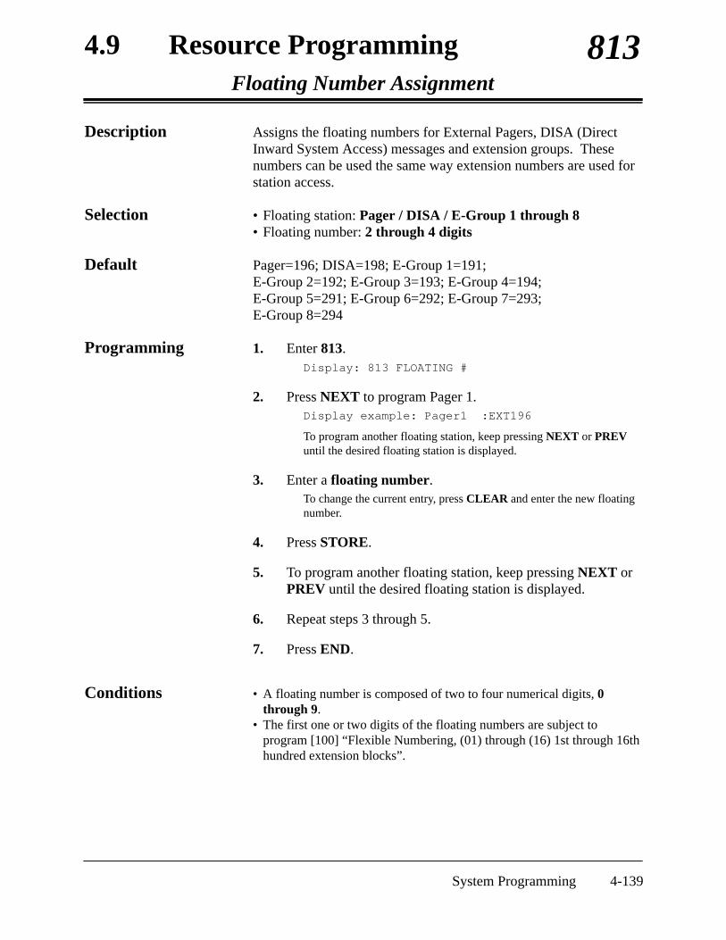
4.9 Resource ProgrammingFloating Number Assignment
813
System Programming 4-139
Description Assigns the floating numbers for External Pagers, DISA (DirectInward System Access) messages and extension groups. Thesenumbers can be used the same way extension numbers are used forstation access.
Selection • Floating station: Pager / DISA / E-Group 1 through 8 • Floating number: 2 through 4 digits
Default Pager=196; DISA=198; E-Group 1=191; E-Group 2=192; E-Group 3=193; E-Group 4=194; E-Group 5=291; E-Group 6=292; E-Group 7=293; E-Group 8=294
Programming 1. Enter 813.Display: 813 FLOATING #
2. Press NEXT to program Pager 1.Display example: Pager1 :EXT196
To program another floating station, keep pressing NEXT or PREVuntil the desired floating station is displayed.
3. Enter a floating number.To change the current entry, press CLEAR and enter the new floatingnumber.
4. Press STORE.
5. To program another floating station, keep pressing NEXT orPREV until the desired floating station is displayed.
6. Repeat steps 3 through 5.
7. Press END.
Conditions • A floating number is composed of two to four numerical digits, 0through 9.
• The first one or two digits of the floating numbers are subject toprogram [100] “Flexible Numbering, (01) through (16) 1st through 16thhundred extension blocks”.

4.9 Resource ProgrammingFloating Number Assignment (contd.)
813
4-140 System Programming
• Floating numbers and extension numbers should be unique. Doubleentry and incompatible entry for these numbers are invalid. Valid entryexample: 10 and 11, 10 and 110. Invalid entry example: 10 and 106,210 and 21.To avoid making an invalid entry, check the other extension numbers inprograms [003] “Extension Number Set”, [118] “VM ExtensionNumber Assignment” and [124] “Phantom Extension NumberAssignment”. The default of each extension number is as follows:
[003] Extension Number Set11 through 18, 21 through 28
[118] VM Extension Number Assignment295 through 298
[124] Phantom Extension Number AssignmentNot assigned.
• You cannot leave an entry empty.
Feature References Section 3, FeaturesFloating Station

4.9 Resource ProgrammingDISA Built-in Auto Attendant
815
System Programming 4-141
Description Assigns the DISA (Direct Inward System Access) built-in autoattendant number. The extension number and the floating numbercan be assigned as a one digit number and used as a DISA built-inauto attendant number.
Selection • DISA built-in auto attendant number: 0 through 9• Extension number / Floating number: 2 through 4 digits
Default Disable
Programming 1. Enter 815.
Display: 815 DISA AA
2. Press NEXT.
Display example: Dial NO?→
3. Enter a DISA built-in auto attendant number.
To enter DISA AA number 0, you can also press NEXT.
Display example: Dial 0:Disable
4. Enter an extension or floating number.
To change the current entry, press CLEAR and enter the new floatingnumber.
Display example: Dial 0:EXT112
5. Press STORE.
6. To program another DISA AA number, press NEXT orPREV, or SELECT and the desired DISA AA number.
7. Repeat steps 3 through 6.
8. Press END.
Conditions This system can store up to ten programmable DISA built-in autoattendant numbers.
Feature References Section 3, FeaturesDirect Inward System Access (DISA)

4.10 Optional ProgrammingSystem Data Clear
900
4-142 System Programming
Description Clears the system data which you have programmed. The systemwill re-start with the default setting.
Programming 1. Enter 900.
Display: 900 SYS-DATA CLR
2. Press NEXT.
Display: Data Clear?
3. Press STORE.
Conditions None
Feature References None

4.10 Optional ProgrammingSystem Additional Information
990
System Programming 4-143
Description Adds the following programming items, if required:
Displayexample 1110011000101100
Field number (unused)(26)(22) (21) (20)(19)(18)(17)(16) (15)(14)(13)(12)(11)↓ ↓ ↓ ↓ ↓ ↓ ↓ ↓ ↓ ↓ ↓ ↓ ↓ ↓
Area 02
Displayexample 0010100011000001
Field number (10) (9) (8) (7) (6) (5) (4) (unused) (3) (2) (1)↓ ↓ ↓ ↓ ↓ ↓ ↓ ↓ ↓ ↓ ↓
Area 01
Displayexample 0000000001010110
Field number↓ ↓
(unused) (23)
Area 03
Area 04Displayexample 1111111100000000
(reserved) (27)(unused)(25)(24) (unused)Field number↓ ↓ ↓ ↓ ↓ ↓

4.10 Optional ProgrammingSystem Additional Information (contd.)
990
4-144 System Programming
Displayexample
1111111111111111
Field number (45)(44)(43)(42)(41)(40)(39)(38)(37)(36)(35)(34)(33)(32)(31)(30)↓ ↓ ↓ ↓ ↓ ↓ ↓ ↓ ↓ ↓ ↓ ↓ ↓ ↓ ↓ ↓
Area 05
Area 06
Displayexample
1111111111111111
Field number (46)↓

4.10 Optional ProgrammingSystem Additional Information (contd.)
990
System Programming 4-145
Explanation
• CALLTRANSFERFEATURES
• Music on Hold
ConsultationHold
• ExternalFeature Access
• Flash
None
ConsultationHold
Voice MailIntegration
Voice MailIntegration
Voice MailIntegration
• MessageWaiting
• Voice MailIntegration
Call Transfer,Unscreened – toExtension
1
0
0
1
0
0
10
10
0
0
0 : ringback tone1 : Music on Hold
0 : ConsultationHold
1 : disconnection
0 : disconnectionsignal
1 : ExternalFeature Access
0 : disable1 : enable
0 : ConsultationHold
1 : disconnection
0 : 80 ms 1 : 160 ms
00 : 0.5 s 01 : 1.0 s10 : 1.5 s 11 : 2.0 s
00 : 0.5 s01 : 1.0 s10 : 1.5 s11 : 2.0 s
0 : system1 : VPS
0 : initiatingextension
1 : Operator 1
Sound source during transfer.
Result of pressing the hookswitch lightlyand then placing down the handset (duringan outside call; standard telephones only).
Result of pressing the FLASH orFLASH/RCL button on proprietarytelephones (during an outside call).
Enables or disables the dial tone betweenobtaining an outside line and dialing thephone number when using the one-touchdial, redial or speed dial function.
Result of pressing the hookswitch lightly(standard telephones only).
Sets the duration of the DTMF (Dual ToneMulti-Frequency) signals sent to the VoiceProcessing System (VPS) ports.
Sets the time the system waits beforesending DTMF signals (such as a mailboxnumber) to VPS after VPS answers a call.
Sets the time the system waits beforesending DTMF signals (programmed in[113]) to VPS after the VPS calls anextension.
Assigns whether the system or the VPSturns off the Message Waiting lamp whenthe user hears a message recorded in amailbox.
Unused
If an outside party is transferred or parkedand unanswered, assigns whether TransferRecall occurs at the transfer initiatingextension or at Operator 1.
Area Field(1)
(2)
(3)
(4)
(5)
(6)
(7)
(8)
(9)
(10)
(11)
Description Selection Default References01
02

4.10 Optional ProgrammingSystem Additional Information (contd.)
990
4-146 System Programming
Limited CallDuration
ConfirmationTone
Toll Restriction
ConfirmationTone
Dial TypeSelection
Voice MailIntegration
0
1
1
1
0
0
0 : both calls1 : outgoing calls
only
0 : disable1 : enable
0 : no check1 : check
0 : disable1 : enable
0 : 60 %1 : 67 %
0 : extensionnumber
1 : free
If Limited Call Duration is enabled inprogram [502] “Extension-to-Outside LineCall Duration Limit”, assigns if LimitedCall Duration is done for both outgoing andincoming calls or for outgoing calls only.
Allows you to remove confirmation tone 4.By default, a beep tone is emitted when athree-party conference is started / ended.
Determines if the dialed “ ” and “#” will bechecked by Toll Restriction. This assignmentis required for certain central offices (CO) toprevent toll fraud. Some COs ignore theuser-dialed “ ” and “#”. If your CO is sucha type, select “0” (no check).
Unused
Allows you to remove Confirmation Tone 3.This tone is sent when a conversation isestablished just after dialing the featurenumber for accessing the following features:Call Pickup, Paging, Paging Answer, Trunk(Outside Line) Answer From Any Station(TAFAS), Hold Retrieve and Call ParkRetrieve.
An outside line set to pulse or call blockingmode in program [402] “Dial ModeSelection” can have two settings. Thisassigns the pulse break ratio during dialpulsing. Select an appropriate ratiodepending on the standard in your country.
Assigns if an extension’s mailbox numberis substituted by the extension number or itis programmable (free). If a call isforwarded or rerouted to the VoiceProcessing System (VPS), this systemautomatically transmits the mailbox numberto the VPS to specify the user’s mailbox.To make it programmable, select “1(free)”, then assign the number in program[609] “Voice Mail Access Codes”.
Area Field(12)
(13)
(14)
(15)
(16)
(17)
(18)
Description Selection Default References02

4.10 Optional ProgrammingSystem Additional Information (contd.)
990
System Programming 4-147
Special DisplayFeatures — CallDirectory
• BackgroundMusic (BGM)
• BackgroundMusic (BGM)– External
• Music on Hold
None
None
None
Voice MailIntegration
None
None
Caller ID
Direct InwardSystem Access(DISA)
OutgoingMessage (OGM)
0
1
01
0
1
1
1
1
1
1
1
0 : names1 : numbers
0 : internal musicsource
1 : external musicsource
00 : 630 ms01 : 830 ms10 : 1030 ms
0 : normal1 : distinctive
0 : 84-1000 ms1 : 200-1000 ms
0 : prevent1 : allow
0 : prevent1 : allow
0 : disable1 : enable
0 : enable1 : disable
0 : IRNA1 : busy tone is
sent
0 : immediately1 : after 10 seconds
Determines the initial display of a digitaldisplay proprietary telephone (KX-T7431/KX-T7433/KX-T7436/KX-T7235) inStation Speed Dialing.
Determines the source of Music Source 1for Music on Hold and BGM. Internalmusic source is not available for yoursystem.
Selects inter-digit pause for pulse dialing.
Selects intercom dial tone frequency.
Selects the extension–hooking signaldetection time.
Reserved
Prevents or allows a call originated by anAutomated Attendant (AA) port of VoiceProcessing System (VPS) to another AAport.
Prevents or allows sending pulse dialingsignals during an outside call.
Enables or disables the outside line pulsefeedback tone.
Enables or disables the automatic timeadjustment by Caller ID information once aday by the first call received after 3:00AM.
Unused
Selects the result when a call from DISAarrives at a DND extension or a busyextension which disabled Call Waiting.
Sets the time the system waits for IRNA after the OGM.
Area Field(19)
(20)
(21)
(22)
(26)
(23)
(24)
(25)
(27)
(30)
(31 –32)
(33)
(34)
Description Selection Default References02
03
04
05
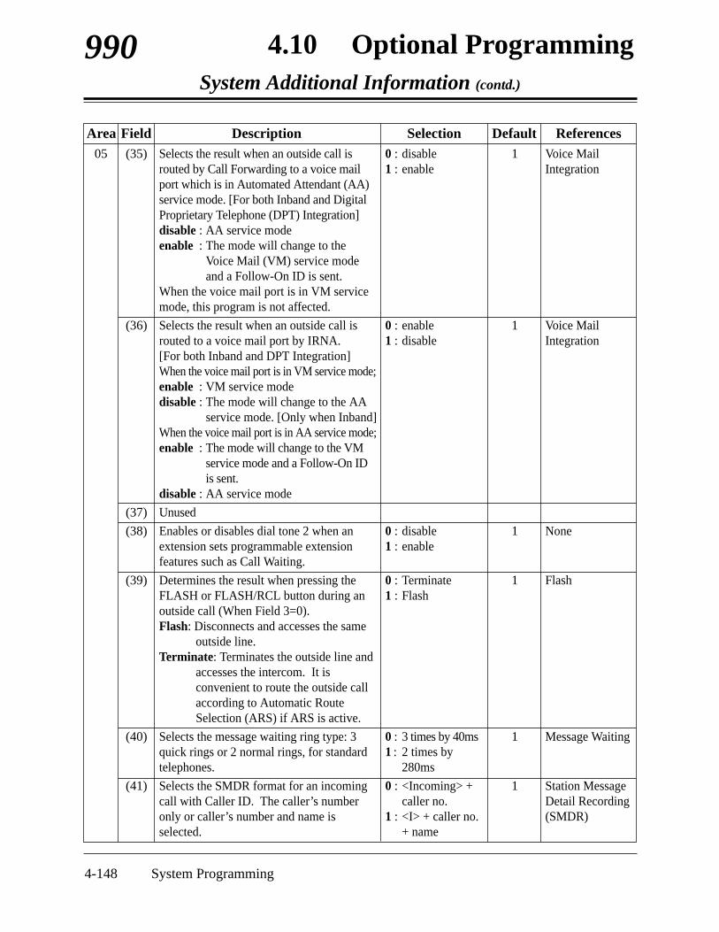
4.10 Optional ProgrammingSystem Additional Information (contd.)
990
4-148 System Programming
Voice MailIntegration
Voice MailIntegration
None
Flash
Message Waiting
Station MessageDetail Recording(SMDR)
1
1
1
1
1
1
0 : disable1 : enable
0 : enable1 : disable
0 : disable1 : enable
0 : Terminate1 : Flash
0 : 3 times by 40ms1 : 2 times by
280ms
0 : <Incoming> +caller no.
1 : <I> + caller no.+ name
Selects the result when an outside call isrouted by Call Forwarding to a voice mailport which is in Automated Attendant (AA)service mode. [For both Inband and DigitalProprietary Telephone (DPT) Integration]disable : AA service modeenable : The mode will change to the
Voice Mail (VM) service modeand a Follow-On ID is sent.
When the voice mail port is in VM servicemode, this program is not affected.
Selects the result when an outside call isrouted to a voice mail port by IRNA. [For both Inband and DPT Integration]When the voice mail port is in VM service mode;enable : VM service modedisable : The mode will change to the AA
service mode. [Only when Inband]When the voice mail port is in AA service mode;enable : The mode will change to the VM
service mode and a Follow-On IDis sent.
disable : AA service mode
Unused
Enables or disables dial tone 2 when anextension sets programmable extensionfeatures such as Call Waiting.
Determines the result when pressing theFLASH or FLASH/RCL button during anoutside call (When Field 3=0).Flash: Disconnects and accesses the same
outside line.Terminate: Terminates the outside line and
accesses the intercom. It isconvenient to route the outside callaccording to Automatic RouteSelection (ARS) if ARS is active.
Selects the message waiting ring type: 3quick rings or 2 normal rings, for standardtelephones.
Selects the SMDR format for an incomingcall with Caller ID. The caller’s numberonly or caller’s number and name isselected.
Area Field(35)
(36)
(37)
(38)
(39)
(40)
(41)
Description Selection Default References05

4.10 Optional ProgrammingSystem Additional Information (contd.)
990
System Programming 4-149
SMDR
None
Operator Call
Timed Reminder
Account CodeEntry
1
1
1
1
1
0 : enable1 : disable
0 : IRNA1 : reorder tone is
sent
0 : Operators 1 and 2simultaneously
1 : Operator 1 firstand thenOperator 2
0 : enable1 : disable
0 : not printed out1 : printed out
Enables or disables the SMDR printout forRC (when an incoming call occurs) andAN (when an incoming call is answered).
Selects the result when a call from DISA(Direct Inward System Access) is invalid.
Selects the result of pressing “0” (default);calls operators 1 and 2 at the same time orOperator 1 first and then Operator 2 ifOperator 1 is busy.
Enables or disables the SMDR printoutwhen the Timed Reminder starts and thealarm is not answered.
Programs whether or not the account codeis printed out in the SMDR.
Area Field(42)
(43)
(44)
(45)
(46)
Description Selection Default References05
06

4.10 Optional ProgrammingSystem Additional Information (contd.)
990
4-150 System Programming
Selection • Area code: 01 (area 1) / 02 (area 2) / 03 (area 3) / 04 (area 4) /05 (area 5) / 06 (area 6)
• Field number : 1 through 46• Selection: See “Selection” on pages 4-147 through 4-151.
Default See “Default” shown in the table.
Programming 1. Enter 990.
Display: 990 SYS ADD DATA
2. Press NEXT.
Display: Area NO?→
3. Enter an area code (01 through 06).
Display example: 0010100011000001
4. Keep pressing or to move the cursor to the desiredfield.
5. Enter your selection (0 or 1).
To change the current entry, press STORE and enter the newselection.
6. To program another field, repeat steps 4 and 5.
7. Press STORE.
8. To program another area, press SELECT and the desiredarea code.
9. Repeat steps 4 through 8.
10. Press END.
Conditions None
Feature References See “References” on pages 4-147 through 4-151.

4.10 Optional ProgrammingCOS Additional Information
991
System Programming 4-151
Description (1) Sets the number of digits allowed to dial out during an outside callon a Class of Service (COS) basis. If an outside party hangs up andthe extension user tries to dial out still on the outside line, thesystem will disconnect the line at the time the assigned number ofdigits are dialed. This program can be added if the Calling PartyControl (CPC) Signal Detection is not provided by the outside line.The Field (1) shown below is used to enter your selection.
(2) Enables or disables Call Forwarding – Follow Me feature on a COSbasis. The Field (2) below is used to enter your selection.
Selection • COS number: 1 through 8, ( =all COS)• Field number : 1 or 2• Selection for field (1):
0000: no limit / 0001: 1 digit / 0010: 2 digits / 0011: 3 digits /0100: 4 digits / 0101: 5 digits / 0110: 6 digits / 0111: 7 digits /1000: 8 digits / 1001: 9 digits / 1010: 10 digits / 1011: 11 digits /1100: 12 digits / 1101: 13 digits / 1110: 14 digits / 1111: 15 digits
• Selection for field (2): 0 : disable / 1 : enable
Default Field 1: All COS – 0000 / Field 2: All COS – 1
Programming 1. Enter 991.
Display: 991 COS ADD DATA
2. Press NEXT.
Display: COS NO?→
3. Enter a COS number.
Display example: 1111111111110000
4. Keep pressing or to move the cursor to the desiredfield.
Displayexample 1111111111110000
Field number (unused) (2) (1)↓ ↓ ↓

4.10 Optional ProgrammingCOS Additional Information (contd.)
991
4-152 System Programming
5. Enter your selection (0 or 1).
To change the current entry, press STORE and the new selection.
6. To program another field, repeat steps 4 and 5.
7. Press STORE.
8. To program another COS, press SELECT and the desiredCOS number.
9. Repeat steps 4 through 8.
10. Press END.
Conditions None
Feature References Section 3, FeaturesCall Forwarding – Follow MeCalling Party Control (CPC) Signal DetectionClass of Service (COS)

Section 5List
This section lists the tone, ring tone and default values ofsystem programming.

5.1 Tone / Ring Tone
5-2 List
1 sec
Confirmation Tone 1
Confirmation Tone 2
Confirmation Tone 3
Confirmation Tone 4
Dial Tone 1
Dial Tone 2
Dial Tone 4
Busy Tone
Ringback Tone 1
Ringback Tone 2
Do Not Disturb (DND)Tone
Reorder Tone
Dial Tone 3
<TONE>
Outside-to-Outside LineCall Limit Warning Tone

5.1 Tone / Ring Tone
List 5-3
Hold Alarm
15 sec<TONE>
Call Waiting Tone 1(outside/intercom)
<RING TONE>1 sec
Outside Calls /Outside Call Hold Recall
Intercom Calls /Intercom Hold Recall
Doorphone Calls /Timed Reminder
Callback Ringing (Camp-on Recall)
5 sec
Call Waiting Tone 2 (outside)
Call Waiting Tone 2(intercom)

Manager Programming[000] Date and Time Set[001] System Speed Dialing Number Set[002] System Speed Dialing Name Set[003] Extension Number Set
[004] Extension Name Set[005] Flexible CO Button Assignment
[006] Operator / Manager ExtensionAssignment
[008] Absent Messages
[009] Quick Dial Number SetSystem Programming
[100] Flexible Numbering[101] Day / Night Service Switching Mode[102] Day / Night Service Starting Time
[103] Automatic Access Outside LineAssignment
[105] Account Codes[106] Station Hunting Type[107] System Password[108] Automatic Hold by CO / DSS Button[110] Caller ID Code Set[111] Caller ID Name Set[113] VM Status DTMF Set
[114] VM Command DTMF Set
[116] ROM Version Display†[117] Voice Mail Number Assignment†[118] Voice Mail Extension Number
Assignment†[119] Voice Mail Extension Group
Assignment
’97 Jan. 1 WED 12:00 AM 12Not StoredNot StoredJack 1-1 through 8-1=11 through 18Jack 1-2 through 8-2=21 through 28Not StoredAll Jacks – CO button 1 through 3 = SingleCO 1 through 3, Others = Not Stored; Ring tone type 2Operator 1=Jack 1; Operator 2 and Manager=Unassigned1: Will Return Soon; 2: Gone Home;3: At Ext %%; 4: Back at %%:%%; 5: Out Until %%/%%; 6: In a Meeting; 7 through 9: Not StoredNot Stored
See page 4-32 and 4-33.ManualEvery Day of the Week – Day=9:00 am /Night=5:00 pm123
Not StoredAll Extension Groups=Disable1234DSS Button=Enable; CO Button=DisableNot StoredNot StoredRBT=1; BT=2; ROT=3; DND=4; Answer=5;Disconnect=#9; Confirm =9; FWD VM RBT=6; FWD VM BT=7; FWD EXT RBT=8LV-MSG=H; GETMSG= H; AA-SVC=#8;VM-SVC=#6Not ApplicableNot StoredVM-1=295; VM-2=296; VM-3=297; VM-4=298All Voice Mail Numbers=EXG 1
5.2 Default Values
5-4 List
5.2 Default Values
ADDRESS PROGRAM DEFAULT
†: Available when the Digital Super Hybrid System is connected to a DigitalProprietary Telephone capable Panasonic Voice Processing System (onethat supports digital proprietary telephone integration; e.g. KX-TVS100).
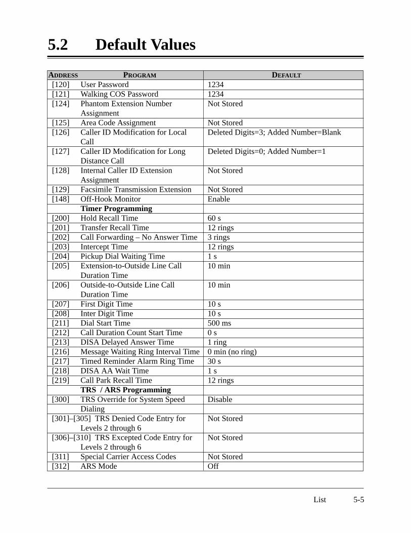
[120] User Password[121] Walking COS Password[124] Phantom Extension Number
Assignment[125] Area Code Assignment[126] Caller ID Modification for Local
Call[127] Caller ID Modification for Long
Distance Call[128] Internal Caller ID Extension
Assignment[129] Facsimile Transmission Extension[148] Off-Hook Monitor
Timer Programming[200] Hold Recall Time[201] Transfer Recall Time[202] Call Forwarding – No Answer Time[203] Intercept Time[204] Pickup Dial Waiting Time[205] Extension-to-Outside Line Call
Duration Time[206] Outside-to-Outside Line Call
Duration Time[207] First Digit Time[208] Inter Digit Time[211] Dial Start Time[212] Call Duration Count Start Time[213] DISA Delayed Answer Time[216] Message Waiting Ring Interval Time[217] Timed Reminder Alarm Ring Time[218] DISA AA Wait Time[219] Call Park Recall Time
TRS / ARS Programming[300] TRS Override for System Speed
Dialing[301]–[305] TRS Denied Code Entry for
Levels 2 through 6 [306]–[310] TRS Excepted Code Entry for
Levels 2 through 6[311] Special Carrier Access Codes[312] ARS Mode
12341234Not Stored
Not StoredDeleted Digits=3; Added Number=Blank
Deleted Digits=0; Added Number=1
Not Stored
Not StoredEnable
60 s12 rings3 rings12 rings1 s10 min
10 min
10 s10 s500 ms 0 s1 ring0 min (no ring)30 s1 s12 rings
Disable
Not Stored
Not Stored
Not StoredOff
5.2 Default Values
List 5-5
ADDRESS PROGRAM DEFAULT

[313] ARS Time
[314]–[321] ARS Leading Digit Entry forPlans 1 through 8
[322]–[329] ARS Routing Plans 1 through 8[330] ARS Modify Removed Digit[331] ARS Modify Added Number[332] Extra Entry Table Selection[333] TRS Entry Code Assignment for
Extra Table[334] Emergency Dial Number Set
Outside Line Programming[400] Outside Line Connection
Assignment[402] Dial Mode Selection[403] Pulse Speed Selection[404] DTMF Time[405] CPC Signal Detection Incoming Set[406] Caller ID Assignment[407]–[408] DIL 1:1 Extension—Day/Night[409]–[410] Intercept Extension—Day/Night[411] Host PBX Access Codes[412] Pause Time[413] Flash Time[414] Disconnect Time[415] CPC Signal Detection Outgoing Set[416] Reverse Circuit Assignment[417] Outside Line Name Assignment
COS Programming[500]–[501] Toll Restriction Level—Day/
Night[502] Extension-to-Outside Line Call
Duration Limit[503] Call Transfer to Outside Line[504] Call Forwarding to Outside Line[505] Executive Busy Override[506] Executive Busy Override Deny[507] Do Not Disturb Override[508] Account Code Entry Mode
Every Day of the Week:Time-A=8:00 am; Time-B=5:00 pm; Time-C=9:00 pm; Time-D=DisableNot Stored
Not StoredAll Modification Tables=0 (digits)Not StoredExcept-2Not Stored
Location 01=991; Others=Not Stored
All Outside Lines=Connect
All Outside Lines=DTMFAll Outside Lines=10 ppsAll Outside Lines=80 msAll Outside Lines=400 ms All Outside Lines=DisableAll Outside Lines=Disable—Day/NightAll Outside Lines=Disable—Day/NightNot StoredAll Outside Lines=1.5 sAll Outside Lines=600 msAll Outside Lines=1.5 sDisableRegularNot Stored
COS 1 through 7=Level 1—Day/Night;COS 8=Level 7—Day/NightAll COS=Disable
All COS=DisableAll COS=DisableAll COS=DisableAll COS=EnableAll COS=DisableAll COS=Option
ADDRESS PROGRAM DEFAULT
5.2 Default Values
5-6 List

[509] Off-Hook Call Announcement(OHCA)Extension Programming
[600] EXtra Device Port[601] Class of Service[602] Extension Group Assignment[603]–[604] DIL 1:N Extension and Delayed
Ringing—Day/Night[605]–[606] Outgoing Permitted Outside
Line Assignment—Day/Night[607]–[608] Doorphone Ringing Assignment
—Day/Night[609] Voice Mail Access Codes
†[610] Live Call Screening Recording ModeAssignmentResource Programming
[800] SMDR Incoming / Outgoing CallLog Printout
[801] SMDR Format[802] System Data Printout[803] Music Source Use[804] External Pager BGM[805] External Pager Confirmation Tone[806] Serial Interface (RS-232C)
Parameters[813] Floating Number Assignment
[815] DISA Built-in Auto AttendantOptional Programming
[900] System Data Clear[990] System Additional Information[991] COS Additional Information
All COS=Enable
All Jacks=DisableAll Jacks-1/2=COS 1All Jacks-1/2=Extension Group 1All Jacks-1/2=All Outside Lines= ImmediateRinging—Day/NightAll Jacks-1/2=All OutsideLines=Enable—Day/ NightJack 1-1=Enable; Other Jacks=Disable—Day/NightNot StoredAll Jacks=Stop Rec
Outgoing Calls=All; Incoming Calls=On
Page Length=66; Skip Perforation=0Not ApplicableHold and BGM=EnableAll External Pagers=DisableOnNew Line Code=CR+LF; Baud Rate=9600;Word Length=8; Parity Bit=Mark; Stop Bit=1Pager=196; DISA=198;E-Group 1=191; E-Group 2=192;E-Group 3=193; E-Group 4=194;E-Group 5=291; E-Group 6=292;E-Group 7=293; E-Group 8=294Disable
Not ApplicableSee pages 4-147 through 4-151.See page 4-153.
5.2 Default Values
List 5-7
ADDRESS PROGRAM DEFAULT
†: Available when the Digital Super Hybrid System is connected to a DigitalProprietary Telephone capable Panasonic Voice Processing System (onethat supports digital proprietary telephone integration; e.g. KX-TVS100).

Section 6Troubleshooting
This section provides information for system and telephonetroubleshooting.

6-2 Troubleshooting
6.1 Troubleshooting
6.1.1 Installation
PROBLEM
Extension does not operate.
Improper reset operation.
Noise in external paging.
Volume distortion fromexternal music source.
Speed Dialing or One-Touch Dialing does notfunction.
PROBABLE CAUSE
Bad printed circuit board(Extension Card).
Bad connection betweenthe system and extension.
A telephone with an A-A1relay is connected.
Bad extension.
Induced noise on the wirebetween the system and theamplifier.
Excessive input level fromexternal music source.
Bad programming.
POSSIBLE SOLUTION
Exchange printed circuit board foranother printed circuit board.
Take the extension and plug it intothe same extension port using ashort telephone cord. If thetelephone does not work, theconnection between the system andthe extension must be repaired.
Use a 2 wire cord.Set the A-A1 relay switch of thetelephone to the “OUT” or “OFF”position.
Take the extension and plug it intoanother extension port that isworking. If the telephone does notwork, replace the phone.
Press the Reset Button.
Use a shielded cable as theconnection wire between thesystem and amplifier. A shortshielded cable is recommended.
Decrease the output level of theexternal music source by using thevolume control on the musicsource.
Enter the outside line accessnumber (9, 81 through 83) into pro-gramming.

Troubleshooting 6-3
6.1 Troubleshooting
6.1.2 Connection
Can you dialan extension?
(Continued on thefollowing page.)
Yes
No
Connection between the system and a proprietary telephone:
CAUSE
The T/R is connected to the D1/D2.
D1 ●
T ●
R ●
D2 ●
● D1 ● T● R ● D2
KX-TD308
KX-TD308
extension
SOLUTION
Use the correct cord (inner 2wires are for T/R and theouter 2 wires are for D1/D2).
Connection between the system and a standard telephone:
SOLUTION
Use the correct cord (inner 2wires are for T/R).
CAUSE
The T/R is connected to the D1/D2.
D1 ●
T ●
R ●
D2 ●
●
● T● R ●
extension
Connection between the system and a standard telephone that is polarity-sensitive:
CAUSE
The “T” is connected to the “R”.
D1 ●
T ●
R ●
D2 ●
●
● T● R ●
extension
SOLUTION
Reverse the connections ofthe T/R.
KX-TD308

6-4 Troubleshooting
6.1 Troubleshooting
(Continued from theprevious page.)
NoCan you dialout on anoutside line?
Connection between the central office and the system:
CAUSE
Outside lines are connected to the T2/T1.
●
●
● T2 ● R1● T1● R2
Outside line KX-TD308
SOLUTION
Reconnect the outside linesto the T1/R1 or T2/R2 of thetelephone jack using 2-conductor wiring.
Outside lines are connected to the T2/R1.
●
●
● T2 ● R1● T1● R2
Outside line KX-TD308
6.1.3 Operation
PROBLEM
• When using the speaker-phone mode with aproprietary telephoneKX-T7130 or KX-T7030,nothing is audible.
• When using the speaker-phone/monitor mode witha digital proprietarytelephone, nothing isaudible.
The unit does not ring.
PROBABLE CAUSE
• The HANDSET /HEADSET selector ofthe KX-T7130 or KX-T7030 is set to the“HEADSET” position.
• The “HEADSET” modeis selected by StationProgramming,“Handset/Headset Selection”.
The Ringer VolumeSelector is set to “OFF”.
POSSIBLE SOLUTION
• When the headset is not used, setthe HANDSET / HEADSETselector to the “HANDSET”position.
• When the headset is not used,select the “HANDSET” mode byStation Programming.
Set to “HIGH” or “LOW”.

Troubleshooting 6-5
6.1 Troubleshooting
6.1.4 Using the Reset Button
If the system does not operate properly, use the Reset Button.Before using the Reset Button, try the system feature again toconfirm whether there definitely is a problem or not.
Pressing the Reset Button causes the following:
1. Camp-on is cleared.2. Calls on Hold are terminated.3. Calls on Exclusive Hold are terminated.4. Calls in progress are terminated.5. Call Park is cleared.
All other data stored in memory is not cleared.
OperationIf the system does not operate properly,
1. Press the Reset Button with a pointed tool.
When the power supply stops, certain extension is automaticallyconnected straight to specific outside line:
Extension (T, R) of jack number 1 .........................CO 1
Connect a standard telephone to the above extension jack.
PROBLEM
During a power failure,extensions connected tojack numbers 1 do notoperate.
Originating an outside call,Call Transfer, orConference cannot beperformed.
PROBABLE CAUSE
• A DPT or APT isconnected to the jack.
• The dialing mode (toneor pulse) is improper.
The corresponding CObutton does not exist on theproprietary telephone.
POSSIBLE SOLUTION
• Disconnect the DPT or APT andconnect a standard telephone.
• Set the Tone / Pulse switch to theother position.
Program the CO button. SeeSection 4.2 [005] “Flexible COButton Assignment”.

Printed in the United Kingdom PSQX1348WA S0199MT1099SA (M)
See MorePanasonic Manuals
www.voicesonic.comPhone: 877-289-2829
Panasonic Telephone Systems


![1728EX+ : Programming Guide - safe-tech · 02 ... Streamline section Streamline Streamline section Streamline section ... 1728EX+ : Programming Guide Keywords [English] Created Date:](https://img.dokumen.tips/doc/110x75/5b84d6a77f8b9aec488d14a4/1728ex-programming-guide-safe-02-streamline-section-streamline-streamline.jpg)


![1738EX+ : Programming Guide - Alarme Provinciale · Streamline section Streamline section ... SINGLE ZONE CONNECTIONS N.C. Contacts, ... Programming Guide Keywords [English] Created](https://img.dokumen.tips/doc/110x75/5af90bb87f8b9ad2208d62a8/1738ex-programming-guide-alarme-section-streamline-section-single-zone.jpg)