Embed Size (px)
Citation preview

Section 3
VOC Controls
EPA/452/B-02-001

Section 3.2
VOC Destruction Controls
EPA/452/B-02-001

Chapter 2
Incinerators
William M. VatavukInnovative Strategies and Economics Group, OAQPSU.S. Environmental Protection AgencyResearch Triangle Park, NC 27711
Donald R. van der Vaart & James J. SpiveyResearch Triangle InstituteResearch Triangle Park, NC 27709
September 2000
EPA/452/B-02-001
2-2
Contents
2.1 Introduction ........................................................................................................................................... 2.-3
2.2 Process Description .............................................................................................................................................. 2-32.2.1 Thermal Incinerators .................................................................................................................. 2-62.2.2 Catalytic Incinerators ............................................................................................................... 2-102.2.3 Other Considerations: Packaged versus Field-Erected Units, Auxiliary Equipment ............... 2-132.2.4 Technology Comparison .......................................................................................................... 2-15
2.3 General Treatment of Material and Energy Balances ............................................................................ 2-16
2.4 Design Procedures ............................................................................................................................... 2-182.4.1 Steps Common to Thermal and Catalytic Units ........................................................................ 2-182.4.2 Steps Specific to Thermal Units ............................................................................................... 2-232.4.3 Steps Specific to Catalytic Units .............................................................................................. 2-29
2.5 Cost Analysis ....................................................................................................................................... 2-352.5.1 Estimating Total Capital Investment ........................................................................................ 2-35
2.5.1.1 Equipment Costs, EC ................................................................................................. 2-352.5.1.2 Installation Costs ....................................................................................................... 2-40
2.5.2 Estimating Total Annual Cost .................................................................................................. 2-412.5.2.1 Direct Annual Costs .................................................................................................. 2-412.5.2.2 Indirect Annual Costs ............................................................................................... 2-47
2.5.3 Cost Comparison for Example Case .......................................................................................... 2-47
2.6 Acknowledgements .............................................................................................................................. 2-48
References .................................................................................................................................................. 2-49

2-3
2.1 Introduction
Incineration, like carbon adsorption, is one of the best known methods of industrial gaswaste disposal. Unlike carbon adsorption, however, incineration is an ultimate disposal method inthat the objectionable combustible compounds in the waste gas are converted rather than collected.On the other hand, carbon adsorption allows recovery of organic compounds which may havemore value as chemicals than just their heating value. A major advantage of incineration is thatvirtually any gaseous organic stream can be incinerated safely and cleanly, provided properengineering design is used.
The particular application of both thermal and catalytic incineration to gaseous waste streamscontaining volatile organic compounds (VOCs) is discussed here. The U.S. EnvironmentalProtection Agency defines any organic compound to be a VOC unless it is specifically determinednot to be a VOC. Indeed, a number of organics (e.g., methane) are specified as not being VOCs.Although both VOC and non-VOC organic compounds are combustible and are therefore importantin the design of the incinerator, this distinction is important since it is the control of VOCs that isregulated.
2.2 Process Description
Seldom is the waste stream to be combusted a single organic compound. Rather, it iscommon to have a complex mixture of organic compounds. This mixture is typically analyzed forcarbon, hydrogen, oxygen, and other elements; and an empirical formula is developed whichrepresents the mixture. Combustion of such a mixture of organic compounds containing carbon,hydrogen, and oxygen is described by the overall exothermic reaction:
C H O + x + y
- z
O xC O + y
x y z 4 2 22 2 2
⇒ H O (1.2)
The complete combustion products CO2 and H
2O are relatively innocuous, making
incineration an attractive waste disposal method. When chlorinated sulfur-containing compoundsare present in the mixture, the products of complete combustion include the acid components HClor SO
2, respectively, in addition to H
2O and CO
2. In general, these streams would require removal
of the acid components by a scrubber unit, which could greatly affect the cost of the incinerationsystem. (The sizing and costing of these scrubbers is covered in the “Wet Scrubbers” chapter ofthis Manual.)
The heart of an incinerator system is a combustion chamber in which the VOC-containingwaste stream is burned. Since the inlet waste gas stream temperature is generally much lower than

2-4
that required for combustion, energy must be supplied to the incinerator to raise the waste gastemperature. Seldom, however, is the energy released by the combustion of the total organics(VOCs and others) in the waste gas stream sufficient to raise its own temperature to the desiredlevels, so that auxiliary fuel (e.g., natural gas) must be added.
The combustion of the waste gases may be accomplished in a thermal incinerator or in acatalytic incinerator. In the catalytic incinerator a catalyst is used to increase the rate of thecombustion reaction, allowing the combustion to occur at lower temperatures. Because the catalyticprocess operates at a lower temperature than the thermal process, less auxiliary fuel may berequired in the catalytic process to preheat the waste gas.
Auxiliary fuel requirements may also be decreased, and energy efficiency improved, byproviding heat exchange between selected inlet streams and the effluent stream. The effluentstream containing the products of combustion, along with any inerts that may have been present inor added to the inlet streams, can be used to preheat the incoming waste stream, auxiliary air, orboth via a “primary”, or recuperative, heat exchanger. It is useful to define the fractional energyrecovery by the preheater or primary heat exchanger as follows:
F ra ctio na l E nergyR ecovery
= E nergy a c tu ally reco vered flue ga s
M a xim u m en erg y recovera ble if flu e ga s a p proa cheslo w est tem p erature a va ila b le to h ea t exc h an g er
(2.2)
The energy actually recovered, the numerator of Equation 2.2, is the increase in sensibleheat of the gas, e.g., waste gas or waste gas plus dilution air, being heated. The maximum energyrecoverable would be the decrease in sensible heat of the flue gas, if it were cooled to the temperatureof the incoming waste gas. While this maximum energy recovery would be attained only with avery large heat exchanger, the concept of fractional energy recovery is useful in expressing theextent of the improvement in energy efficiency using a “primary” heat exchanger.
Energy efficiency can be further improved by placing another (“secondary”) exchangerdownstream of the primary exchanger to recover additional energy from the effluent stream (e.g.,to generate low pressure process steam or hot water). However, secondary energy recovery isgenerally not used, unless there is a specific on site use for the steam or hot water.
The majority of industrial gases that contain VOCs are dilute mixtures of combustiblegases in air. In some applications, such as air oxidation processes, the waste gas stream is verydeficient in oxygen. Depending on the oxygen content of the waste stream, auxiliary air may berequired to combust the total organic content of the waste gas as well as any auxiliary fuel that hasbeen used.

2-5
The concentration of combustible gas in the waste gas stream plays an integral role in thedesign and operation of an incinerator. From a cost standpoint, the amount of air in excess of thestoichiometric amounts should be minimized. For safety reasons, however, any mixture within theflammability limits, on either the fuel-rich or fuel-lean side of the stoichiometric mixture, presents anunacceptable fire hazard as a feed stream to the incinerator. The lower, or fuel-lean, explosive limit(LEL) of a given organic compound defines the minimum concentration of that compound in airthat can produce more energy than is needed to raise its own temperature to the ignition point(e.g., ignite). Similarly, the upper, or fuel-rich, explosive limit (UEL) represents the highestconcentration of the organic in air that is ignitable. In the latter case, air is limiting the reaction.Both the LEL and the UEL are measured at ambient conditions. Empirically, it has been found thatmixtures of hydrocarbons in air at their LEL have a heating value of approximately 50 Btu/scf.
Since the majority of industrial waste gases that contain VOCs are dilute mixtures ofcombustible gases in air, their heating value is low and their oxygen content exceeds that requiredto combust both the waste organics (VOCs and others) and the auxiliary fuel. If a waste gasabove 50 percent LEL (about 25 Btu/scf) is encountered, it must be diluted to satisfy fire insuranceregulations. Generally, the streams are brought to below 25 percent LEL, although concentrationsfrom 25 percent to 50 percent are permitted provided the waste stream is continuously monitoredby LEL monitors. Because air is the usual diluent gas, care must be taken with preheating thediluted stream so that it remains below about 1200oF. (See discussion below on preheating.) Atable showing LEL, UEL, and heats of combustion for selected organic compounds is given inAppendix A.
The goal of any incineration system is to control the amount of VOCs released to theenvironment. Performance of a control device such as an incinerator can be described by acontrol efficiency in percent (%), defined according to the following equation:
C on tro l E ff.In le t m ass ra te V O C - O u tle t m ass ra te V O C
In le t m ass ra te V O C = 100
× (2.3)
It is important to note, however, that incomplete combustion of the inlet VOCs couldresult in the formation of other VOCs not originally present. For example, the incomplete oxidationof dichloroethane can yield vinyl chloride. Both of these compounds are VOCs. The definitiongiven in Equation 2.3 would still be meaningful, however, as long as the newly formed VOC (e.g.,vinyl chloride) is detected. This situation necessitates the complete chemical analysis of the inletand outlet gas streams to confirm compliance with State and Federal regulations.

2-6
Performance of an incinerator can also be measured solely by the outlet VOC concentration,usually in parts per million by volume (ppmv).
There are a number of different incinerator designs. These designs can be broadly classifiedas thermal systems and catalytic systems. Thermal systems may be direct flame incinerators withno energy recovery, flame incinerators with a recuperative heat exchanger, or regenerative systemswhich operate in a cyclic mode to achieve high energy recovery. Catalytic systems include fixed-bed (packed-bed or monolith) systems and fluid-bed systems, both of which provide for energyrecovery. The following sections discuss design aspects of these systems.
2.2.1 Thermal Incinerators
The heart of the thermal incinerator is a nozzle-stabilized flame maintained by a combinationof auxiliary fuel, waste gas compounds, and supplemental air added when necessary (see Figure2.1). Upon passing through the flame, the waste gas is heated from its inlet temperature (e.g.,100oF) to its ignition temperature. The ignition temperature varies for different compounds and isusually determined empirically. It is the temperature at which the combustion reaction rate (andconsequently the energy production rate) exceeds the rate of heat losses, thereby raising thetemperature of the gases to some higher value. Thus, any organic/air mixture will ignite if itstemperature is raised to a sufficiently high level.
The organic-containing mixture ignites at some temperature between the preheat temperatureand the reaction temperature. That is, ignition, as defined in this section, occurs at some pointduring the heating of a waste stream as it passes through the nozzle-stabilized flame regardless ofits concentration. The mixture continues to react as it flows through the combustion chamber.
The required level of VOC control of the waste gas that must be achieved within the timethat it spends in the thermal combustion chamber dictates the reactor temperature. The shorter theresidence time, the higher the reactor temperature must be. The nominal residence time of thereacting waste gas in the combustion chamber is defined as the combustion chamber volumedivided by the volumetric flow rate of the gas. Most thermal units are designed to provide no morethan 1 second of residence time to the waste gas with typical temperatures of 1,200 to 2,000oF.Once the unit is designed and built, the residence time is not easily changed, so that the requiredreaction temperature becomes a function of the particular gaseous species and the desired level ofcontrol. Table 2.1 illustrates the variability in (theoretical) reactor temperatures that is required todestroy 99.99 percent of the inlet mass of various noxious compounds with excess air for a 1-second reactor residence time [1].
These temperatures cannot be calculated a priori, although incinerator vendors can provideguidelines based on their extensive experience. In practice, most streams are mixtures of compounds,

2-7
thereby further complicating the prediction of this temperature. Other studies [2,3,4], which arebased on actual field test data, show that commercial incinerators should generally be run at 1600oFwith a nominal residence time of 0.75 seconds to ensure 98% destruction of non-halogenatedorganics. In some States the reactor temperature and residence time of the unit are specifiedrather than attempting to measure actual levels of VOC control. The selected temperature must bemaintained for the full, selected residence time for combustion to be complete.
These three studies also conclude that mixing is a critical factor in determining the destructionefficiency. Even though it cannot be measured, mixing is a factor of equal or even greater importancethan other parameters, such as temperature. The most feasible and efficient way to improve themixing in an incinerator is to adjust it after start-up. The 98% control level discussed in theprevious paragraph presumes such an adjustment.
Ultimately, once the unit is built, it is the responsibility of the user to operate and maintainthe incinerator to insure compliance with applicable regulations.
Direct Flame Incinerators
Many configurations of thermal incinerators exist with the same goal—to raise the VOC-containing stream to the desired reaction temperature and hold it there for the given reaction time
Figure 2.1: Thermal Incinerator - General Case
Aux Air
Aux FuelCombustionChamber
Emission Sources
Dilution Air
SecondaryEnergy Recovery
Waste GasPreheater Stack

2-8
to achieve the required destruction efficiency. The simplest example of such a system is the directflame incinerator. With reference to Figure 2.1, the direct flame incinerator is comprised only ofthe combustion chamber. The waste gas preheater and the secondary energy recovery heatexchanger are energy recovery devices and are not included as part of the direct flame incinerator.
Recuperative Incinerators
Recuperative incinerators have improved energy efficiency as a result of placing heatexchangers in the hot outlet gas streams. With reference to Figure 2.1, the recuperative incineratoris comprised of the combustion chamber, the waste gas preheater, and, if appropriate, the secondary,energy recovery heat exchanger.
Primary Energy Recovery (Preheating Inlet Streams) - Considerable fuel savings can berealized by using the exit (product) gas to preheat the incoming feed stream, combustion air, orboth via a heat exchanger, as shown in Figure 2.1 in the so-called “recuperative” incinerator.These heat exchangers can recover up to 70% of the energy (enthalpy) in the product gas.
The two types of heat exchangers most commonly used are plate-to-plate and shell-and-tube. Plate-to-plate exchangers offer high efficiency energy recovery at lower cost than shell-and-tube designs. Also, because of their modular configuration, plate-to-plate units can be built toachieve a variety of efficiencies. But when gas temperatures exceed 1000oF, shell-and-tubeexchangers usually have lower purchase costs than plate-to-plate designs. Moreover, shell-and-tube exchangers offer better long-term structural reliability than plate-to-plate units.[5] In anycase, because most incinerators installed are packaged units, the design (and cost) of the recuperativeheat exchangers have already been incorporated.
Table 2.1: Theoretical Reactor Temperatures Required for 99.99 Percent Destruction byThermal Incineration for a 1-Second Residence Time [1]
Compound Temperature, oF
acrylonitrile 1,344allyl chloride 1,276benzene 1,350chlorobenzene 1,4071,2-dichloroethane 1,368methyl chloride 1,596toluene 1,341vinyl chloride 1,369

2-9
Most heat exchangers are not designed to withstand high temperatures, so that most of theenergy needed to reach ignition is supplied by the combustion of fuel in the combustion chamberand only moderate preheat temperatures are sought in practice (<1200oF).
Secondary Energy Recovery (Additional Waste Energy Recovery) - It should be noted,however, that at least some of the energy added by auxiliary fuel in the traditional thermal units (butnot recovered in preheating the feed stream) can still be recovered. Additional heat exchangerscan be added to provide process heat in the form of low pressure steam or hot water for on-siteapplication. Obviously, an in-plant use for such low level energy is needed to realize these savings.
The need for this higher level of energy recovery will be dependent upon the plant site.The additional heat exchanger is often provided by the incineration unit vendor. The cost of thisadditional heat exchanger may be estimated via standard heat exchanger correlations and shouldbe added to the costs estimated using the cost correlations in this section.
Regenerative Incinerators
A distinction in thermal incinerators can now be made on the basis of this limitation in thepreheat temperature. The traditional approach to energy recovery in the units (shown schematicallyin Figure 2.1) still requires a significant amount of auxiliary fuel to be burned in the combustionchamber when the waste gas heating values are too low to sustain the desired reaction temperatureat the moderate preheat temperature employed. Additional savings can, under these conditions,be realized in units with more complete transfer of exit-stream energy. This is the concept behindthe so-called excess-enthalpy or regenerable burner systems. These systems use direct contactheat exchangers constructed of a ceramic material that can tolerate the high temperatures neededto achieve ignition of the waste stream.
The operation of the regenerative system is illustrated in Figure 2.2. The inlet gas firstpasses through a hot ceramic bed thereby heating the stream (and cooling the bed) to its ignitiontemperature. If the desired temperature is not attainable, a small amount of auxiliary fuel is addedin the combustion chamber. The hot gases then react (releasing energy) in the combustion chamberand while passing through another ceramic bed, thereby heating it to the combustion chamberoutlet temperature. The process flows are then switched, now feeding the inlet stream to the hotbed. This cyclic process affords very high energy recovery (up to 95%).
The higher capital costs associated with these high-performance heat exchangers andcombustion chambers may be offset by the increased auxiliary fuel savings to make such a systemeconomical. The costs of these regenerative units will be given separately in the cost correlationspresented in Section 2.4. Regenerative incinerators are not packaged units but are field-erectedonly. Accordingly, the costs given in Section 2.4 for regenerative units are for field-erected units.

2-10
2.2.2 Catalytic Incinerators
Catalytic incinerators employ a bed of active material (catalyst) that facilitates the overallcombustion reaction given in Equation 2.1. The catalyst has the effect of increasing the reactionrate, enabling conversion at lower reaction temperatures than in thermal incinerator units.Nevertheless, the waste stream must be preheated to a temperature sufficiently high (usually from300 to 900oF) to initiate the oxidation reactions. The waste stream is preheated either directly ina preheater combustion chamber or indirectly by heat exchange with the incinerator’s effluent orother process heat or both (Figure 2.3). The preheated gas stream is then passed over the catalystbed. The chemical reaction (combustion) between the oxygen in the gas stream and the gaseouspollutants takes place at the catalyst surface. Catalytic incineration can, in principle, be used todestroy essentially any oxidizable compound in an air stream. However, there are practical limitsto the types of compounds that can be oxidized due to the poisoning effect some species have onthe catalyst. These limits are described below. In addition, most configurations require a lowheating value of the inlet gas and a particulate content which is less than some small value.
Figure 2.2: Regenerable-Type Thermal Incinerator
CombustionChamber
CombustionChamber
C e r a m i c P a c k i n gC o o l i n g G a s
Ceramic PackingHeating Gas
Stack
Emission Source
Stack
Emission Source
Ceramic PackingCooling Gas
Mode B
Mode AC e r a m i c P a c k i n g
H e a t i n g G a s
Aux Air
Aux Air
Aux Fuel
Aux Fuel

2-11
Until recently, the use of catalytic oxidation for control of gaseous pollutants has reallybeen restricted to organic compounds containing only carbon, hydrogen, and oxygen. Gasescontaining compounds with chlorine, sulfur, and other atoms that may deactivate the supportednoble metal catalysts often used for VOC control were not suitably controlled by catalytic oxidationsystems. Catalysts now exist, however, that are tolerant of such compounds. Most of thesecatalysts are single or mixed metal oxides, often supported by a mechanically strong carrier suchas alumina. Perhaps most of the development of poison-tolerant catalysts has focused on theoxidation of chlorine-containing VOCs. These compounds are widely used as solvents anddegreasers and are often the subject of concern in VOC control. Catalysts such as chromia/alumina [6,7], cobalt oxide [8], and copper oxide/manganese oxide [9] have been used for oxidationof gases containing chlorinated compounds. Platinum-based catalysts are active for oxidation ofsulfur containing VOCs, although they are rapidly deactivated by the presence of chlorine.Compounds containing atoms such as lead, arsenic, and phosphorous should, in general, beconsidered poisons for most oxidation catalysts. Nevertheless, their concentration may be sufficientlylow so that the rate of deactivation and therefore, the catalyst replacement costs, could be lowenough to consider catalytic oxidation.
As was the case for thermal units, it is impossible to predict a priori the temperature andresidence time (e.g., inverse space velocity) needed to obtain a given level of conversion of aVOC mixture in a catalytic oxidation system. For example, Table 2.2 from Pope et al. [3] showsthe temperature needed for 80% conversion of a number of VOCs over two oxidation catalysts ina specific reactor design. This table shows that the temperature required for this level of conversionof different VOCs on a given catalyst and of the same VOC on different catalysts can varysignificantly.
Particulate matter, including dissolved minerals in aerosols, can rapidly blind the pores ofcatalysts and deactivate them over time. Because essentially all the active surface of the catalyst is
Figure 2.3: Catalytic Incinerator
Aux Air
Aux FuelPreheaterChamber
CatalystChamber
Waste GasPreheater
Emission Sources
Dilution Air
S e c o n d a r yE n e r g y
R e c o v e r yStack

2-12
contained in relatively small pores, the particulate matter need not be large to blind the catalyst.No general guidelines exist as to particulate concentration and particulate size that can be toleratedby catalysts because the pore size and volume of catalysts vary greatly.
The volumetric gas flow rate and the concentration of combustibles in the gas flowing to thecatalytic incinerator should be constant for optimal operation. Large fluctuations in the flow ratewill cause the conversion of the VOCs to fluctuate also. Changes in the concentration or type oforganics in the gas stream can also affect the overall conversion of the VOC contaminants. Thesechanges in flow rate, organics concentration, and chemical composition are generally the result ofupsets in the manufacturing process generating the waste stream. It may be uneconomical tochange the process for the sake of making the operation of the catalytic incinerator feasible. Insuch cases, thermal incinerators (discussed earlier in this chapter) or carbon adsorption (discussedin Section 3.1 of this Manual) should be evaluated as alternative control technology.
The method of contacting the VOC-containing stream with the catalyst serves to distinguishcatalytic incineration systems. Both fixed-bed and fluid-bed systems are used.
Fixed-Bed Catalytic Incinerators
Fixed-bed catalytic incinerators may use a monolith catalyst or a packed-bed catalyst.Each of these is discussed below.
Monolith Catalyst Incinerators - The most widespread method of contacting the VOC-containing stream with the catalyst is the catalyst monolith. In this scheme the catalyst is a poroussolid block containing parallel, non-intersecting channels aligned in the direction of the gas flow.
Table 2.2: Catalyst Temperatures Required for Oxidizing 80% of Inlet VOC to CO2,
oF for Two Catalyss
Compound CO3O4 Pt - Honeycomb
acrolein 382 294n-butanol 413 440n-propylamine 460 489toluene 476 373n-butyric acid 517 4511, 1, 1-trichloroethane 661 >661dimethyl sulfide - 512
Temperature, oF

2-13
Monoliths offer the advantages of minimal attrition due to thermal expansion/ contraction duringstartup/shutdown and low overall pressure drop.
Packed-Bed Catalytic Incinerators - A second contacting scheme is a simple packed-bedin which catalyst particles are supported either in a tube or in shallow trays through which the gasespass. The first scheme is not in widespread use due to its inherently high pressure drop, comparedto a monolith, and the breaking of catalyst particles due to thermal expansion when the confinedcatalyst bed is heated/cooled during startup/shutdown. However, the tray type arrangement,where the catalyst is pelletized is used by several industries (e.g., heat-set web-offset printing).Pelletized catalyst is advantageous where large amounts of such contaminants as phosphorous orsilicon compounds are present. [10]
Fluid-Bed Catalytic Incinerators
A third contacting pattern between the gas and catalyst is a fluid-bed. Fluid-beds have theadvantage of very high mass transfer rates, although the overall pressure drop is somewhat higherthan for a monolith. An additional advantage of fluid-beds is a high bed-side heat transfer ascompared to a normal gas heat transfer coefficient. This higher heat transfer rate to heat transfertubes immersed in the bed allows higher heat release rates per unit volume of gas processed andtherefore may allow waste gas with higher heating values to be processed without exceedingmaximum permissible temperatures in the catalyst bed. In these reactors the gas phase temperaturerise from gas inlet to gas outlet is low, depending on the extent of heat transfer through imbeddedheat transfer surfaces. The catalyst temperatures depend on the rate of reaction occurring at thecatalyst surface and the rate of heat exchange between the catalyst and imbedded heat transfersurfaces.
As a general rule, fluid-bed systems are more tolerant of particulates in the gas stream thaneither fixed-bed or monolithic catalysts. This is due to the constant abrasion of the fluidizedcatalyst pellets, which helps remove these particulates from the exterior of the catalysts in a continuousmanner. A disadvantage of a fluid-bed is the gradual loss of catalyst by attrition. Attrition-resistant catalysts have been developed to overcome this disadvantage.[76]
2.2.3 Other Considerations: Packaged versus Field-Erected Units, AuxiliaryEquipment
Packaged vs. Field-Erected Units
With the exception of regenerative incinerators, the equipment cost correlations includedin this chapter are for packaged units only. They are not valid for field-erected units. For regenerativeincinerators, the correlations are valid for field-erected units only. Packaged units are units thathave been shop fabricated and contain all elements necessary for operation, except for connection

2-14
to facilities at the site, e.g., utilities. The elements include the combustion chamber, preheater,instrumentation, fan, and the necessary structural steel, piping, and electrical equipment. Thisequipment is assembled and mounted on a “skid” to facilitate installation on a foundation at theplant site. Tie-in to the local emission source is not part of the packaged unit. Units are usuallysized to handle flow rates of < 20,000 scfm, but can be built to accommodate flow rates up to50,000 standard cubic feet per minute (scfm). The cost correlations in this chapter are valid to50,000 scfm for packaged units, except for fluid-bed units which are valid to 25,000 scfm.
Conversely, field-erected units may be built to any desired size. The combustion chamber,preheater, and other equipment items are designed and fabricated individually, and assembled atthe site. However, both the equipment and installation costs of field-erected units are typicallyhigher than those for equivalent-sized packaged units because the factors that improve efficiencyof shop-fabrication, such as uniform working environment, availability of tools and equipment, andmore efficient work scheduling, are generally not available in the field.
Acid Gas Scrubbers
The final outlet stream of any incineration system may contain certain pollutants that mustbe removed. The combustion of sulfur-containing compounds results in SO
2, while chlorinated
compounds yield Cl2 and HCl in the product stream. These acid gases must be removed from the
gas stream if they are present at significant concentrations (regulations for limits on these gasesvary from state to state). This removal can be effected in, for instance, a packed-bed gas absorber(vertical scrubber) in which the flue gas is contacted with a caustic scrubbing liquid. For fluid-bedcatalytic reactors, venturi scrubbers are often used because they provide for particulate removalas well as acid gas scrubbing. In most cases adding a scrubber or absorber significantly increasesthe cost of the incineration unit, sometimes by a factor of two. Costing of absorbers is discussedin the “Gas Absorbers” chapter of this Manual.
If chlorinated VOCs are present in the waste gas, heat exchangers may require specialmaterials of construction. This added expense is not included in the costing procedures outlined inthis section.
Heat Exchangers (Preheaters and Other Waste Energy Recovery Units)
For the thermal and catalytic units having some degree of energy recovery, the cost of theprimary heat exchanger is included in the cost, and its design is usually done by the incineration unitvendor. The cost correlations presented in this chapter include units both with and without energyrecovery. Secondary energy recovery, if desired, requires an additional heat exchanger, which isalso often provided by the incineration unit vendor. Costing procedures for secondary energyrecovery are not included in this section.

2-15
Other Auxiliary Equipment
Additional auxiliary equipment such as hoods, ductwork, precoolers, cyclones, fans, motors,and stacks are addressed separately in other sections of this Manual.
2.2.4 Technology Comparison
Both the thermal and catalytic incineration systems are designed to provide VOC controlthrough combustion at a level in compliance with applicable state and federal requirements. Giventhe wide range of options available, however, it is obvious that not every incinerator will fulfill theserequirements at the same cost. This section presents a first step toward deciding how best to dealwith VOC emission abatement using incinerators considering some qualitative factors pertinent tothe types of incinerators described in this chapter. It is the intent of the remainder of this section toprovide a method by which the cost of VOC control for a particular application can be calculated.
A summary of the principal types of incinerators is presented in Table 2.3. From theearlier discussions, the following factors relating to the presence of contaminants should be consideredby potential users [12]:
• The fouling of the catalyst in a catalytic system is a possibility. Poisons to the systeminclude heavy metals, phosphorous, sulfur and most halogens, although catalysts havebeen developed that are chlorine resistant.
• The possibility of process upsets that could release any of the above poisons or causefluctuations in the heating value to the incinerator would favor a thermal system.
• Except for the No.2 grade, fuel oil should not be considered as auxiliary fuel to a catalytic
system due to the sulfur and vanadium it may contain.[10]
All of the above factors would serve to increase the operating expense of a catalytic unit throughreplacement costs of the catalyst. An additional factor relates to relative energy efficiency of thevarious types of incinerators:
• Thermal units generally require more auxiliary fuel than catalytic units and operate attemperatures that are roughly 1000oF higher. This difference in fuel requirement increasesas the heating value of the waste stream decreases.
In general, a trade-off exists between the higher capital costs of catalytic incinerators andthe higher operating costs of thermal incinerators. This difference will be illustrated by a designexample presented in Section 2.2.4 which treats both technologies.

2-16
2.3 General Treatment of Material and Energy Balances
In the sizing and costing of the incinerator and the calculation of the auxiliary fuel requirements,it is necessary to make material and energy balances around the entire incinerator unit and aroundcertain parts of the unit, such as the combustion chamber or the preheater. This section presents ageneral approach to making these balances.
These balances are based on the law of conservation of mass and energy. They can bestated in general equation form as
In - O u t + G enera tion = A ccum u la tion (2.4)
Because the incineration process is a steady-state process, the accumulation term is zero andthe equation becomes:
In - O u t + G en era tio n = 0 (2.5)
For mass balances it is useful to restrict the balances to be made on the mass of each atomicspecies so that for mass balances the generation term becomes zero. However, because thecombustion reaction liberates energy, the energy balances around equipment where combustiontakes place would include a generation term. Thus, the simplified equations are
In - O ut fo r stea d y sta te m a ss b a la n ces = , 0 − (2.6)
In - O u t + G en era tion
fo r stea dy sta te en erg y ba la nces
=
0 ,
− (2.7)
Table 2.3: Principal VOC Incineration Technologies
Thermal Systems Catalytic Systems
- Direct Flame Incinerator - Fixed-Bed- Recuperative Incinerator (Direct Flame with - Monolith Recuperative Heat Exchanger) - Packed-Bed- Regenerative Incinerator Operating in a Cycle Mode - Fluid-Bed

2-17
For the incineration process the two terms In and Out are generally mass terms (for amass balance) of the form,
�m q= ρ (2.8)
where� = density (mass per unit volume)Q = volumetric flow rate (volume per unit time)
or sensible heat terms (for an energy balance) of the form,
( )� �Q m h q p T Tref= = −∆ ρ (2.9)
whereC
�= heat capacity
T = temperature
The reference temperature, Tref
, is often taken to be zero or the temperature of a convenient
stream, e.g., the inlet gas stream, in whatever units T is in, so the Tref
term may not appear in theequations. When the reference temperature is taken as zero, the sensible heat terms become
�Q r Q C Tp= (2.10)
Energy losses, HL, are also part of the Out term and, for the incinerator process, are taken here to
be 10% of the total energy input to the incinerator.
For the incineration process, the generation term for energy balances accounts for theenergy released through the combustion reactions. This term is generally of the form
�Q r Q ( h )c= − ∆ (2.11)
where(-∆h
c) = heat of combustion.
2-18
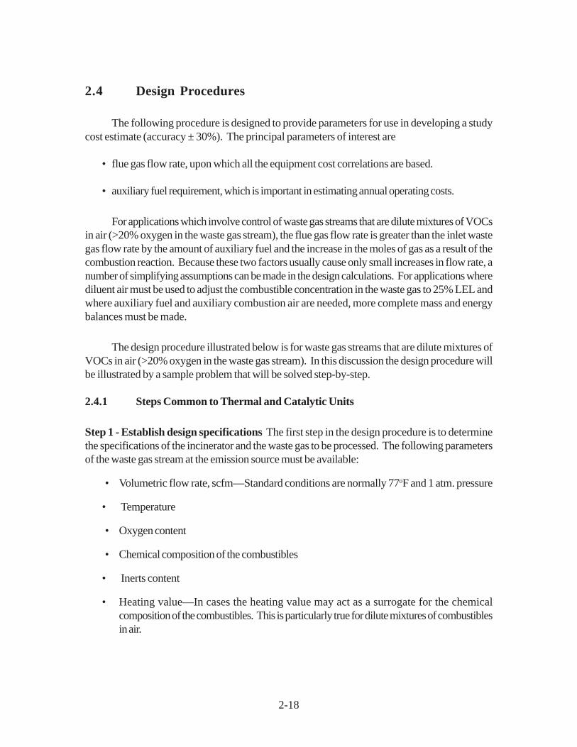
2.4 Design Procedures
The following procedure is designed to provide parameters for use in developing a studycost estimate (accuracy ± 30%). The principal parameters of interest are
• flue gas flow rate, upon which all the equipment cost correlations are based.
• auxiliary fuel requirement, which is important in estimating annual operating costs.
For applications which involve control of waste gas streams that are dilute mixtures of VOCsin air (>20% oxygen in the waste gas stream), the flue gas flow rate is greater than the inlet wastegas flow rate by the amount of auxiliary fuel and the increase in the moles of gas as a result of thecombustion reaction. Because these two factors usually cause only small increases in flow rate, anumber of simplifying assumptions can be made in the design calculations. For applications wherediluent air must be used to adjust the combustible concentration in the waste gas to 25% LEL andwhere auxiliary fuel and auxiliary combustion air are needed, more complete mass and energybalances must be made.
The design procedure illustrated below is for waste gas streams that are dilute mixtures ofVOCs in air (>20% oxygen in the waste gas stream). In this discussion the design procedure willbe illustrated by a sample problem that will be solved step-by-step.
2.4.1 Steps Common to Thermal and Catalytic Units
Step 1 - Establish design specifications The first step in the design procedure is to determinethe specifications of the incinerator and the waste gas to be processed. The following parametersof the waste gas stream at the emission source must be available:
• Volumetric flow rate, scfm—Standard conditions are normally 77oF and 1 atm. pressure
• Temperature
• Oxygen content
• Chemical composition of the combustibles
• Inerts content
• Heating value—In cases the heating value may act as a surrogate for the chemicalcomposition of the combustibles. This is particularly true for dilute mixtures of combustiblesin air.

2-19
• Particulate content—The particulate content is important if catalytic incinerators are to becoated. An upstream filter may suffice if particulate content is too high. Fluid-bed catalyticincinerators can tolerate higher particulate contents than fixed-bed catalytic incinerators.
The following parameters must be specified for the incinerator:
• Desired control efficiency—This efficiency should be based on requirements dictated byrelevant state and federal regulations.
• Combustion chamber outlet temperature—This temperature may also be based onrequirements of a regulation or on recommendations developed during regulatorydevelopment.
• Desired percent energy recovery—The desired percent energy recovery should be theresult of a process optimization in which costs of incinerators with several different levelsof energy recovery are estimated and the minimum cost design selected. The tradeoff isbetween the capital cost of the energy recovery equipment and the operating (fuel) cost.
Specifications for the sample problem are given in Table 2.4.
Step 2 - Verify that the oxygen content of the waste gas exceeds 20% There must besufficient oxygen in the waste gas to support the combustion of the waste organics (includingVOCs) and the auxiliary fuel, if auxiliary fuel is needed. It may be necessary to add auxiliary air ifthe oxygen content is less than about 20%. This example is based on streams that contain >20%oxygen, as shown below for 1000 ppmv of benzene and methylchloride:
( ) ( )A ir C on ten t V o l
ppm ppm = -
- = , . %
, ,.1 0 0
1 0 0 0
1 01 0 0
1 0 0 0
1 01 0 0 9 9 8 %6 6× × (2.12)
This gives the oxygen content in percent as:
O xygen C on ten t = = 98 .8% 0 209 20 86%× . . (2.13)
where 0.209 is the concentration of oxygen in air.
Step 3 - Calculate the LEL and the Percent of the LEL of the gas mixture Note: If thewaste stream contains a significant amount of inerts in addition to the nitrogen associated with the

2-20
oxygen in air, the calculation of LEL (and UEL) loses meaning since the LEL (and UEL) is measuredin mixtures of organic with air only. A complete chemical analysis is necessary to complete thedesign procedure in such a case.
The example chosen here is typical, in that there is more than one VOC component in thegas stream. An approximate method to calculate the LEL of a mixture of compounds, LEL
mix, is
given by Grelecki [13] as
L E Lx
x L E Lm ix
j
ii =
n
j
j =
n
=
∑
∑
−
1
1
1
(2.14)
wherex
i= volume fraction of combustible component i
LELj
= lower explosive limits of combustible component j (ppmv)n = number of combustible components in mixture
Tabla 2.4: Especificaciones para el Problema de Muestra
Variable ValorRelaciPreheater Inlet Wast Gas Vol. Flow Rate, Q
wi, scfm 20,000
Preheater Inlet Waste Gas Temp., Twi
, oF 100Composition
- Benzene Cointent, ppmv 1000- Methyl Chloride Content, ppmv 1000- Air Content Balance
Particulate Content NegligibleMoisture Content NegligibleDesired Control Efficiency, % 98Desired Percent Energy Recovery, HR% 70
2-21
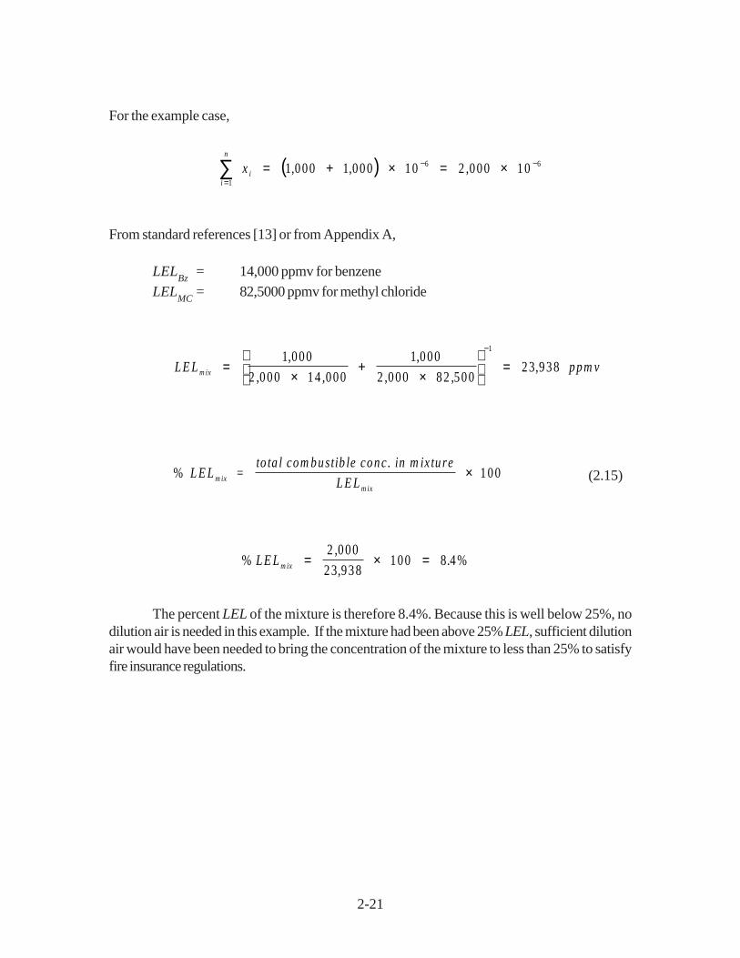
For the example case,
( )i
n
ix=
− −∑ = + × = ×1
6 61 000 1 000 10 2 000 10, , ,
From standard references [13] or from Appendix A,
LELBz
= 14,000 ppmv for benzene
LELMC
= 82,5000 ppmv for methyl chloride
L E L ppm vm ix =×
+×
=
−1 000
2 000 14 000
1 000
2 000 82 50023 938
1,
, ,
,
, ,,
% = 100L E Lto ta l com bustib le conc. in m ix tu re
L E Lm ixm ix
× (2.15)
%,
,.L E L m ix = × =
2 000
23 938100 8 4%
The percent LEL of the mixture is therefore 8.4%. Because this is well below 25%, nodilution air is needed in this example. If the mixture had been above 25% LEL, sufficient dilutionair would have been needed to bring the concentration of the mixture to less than 25% to satisfyfire insurance regulations.
2-22
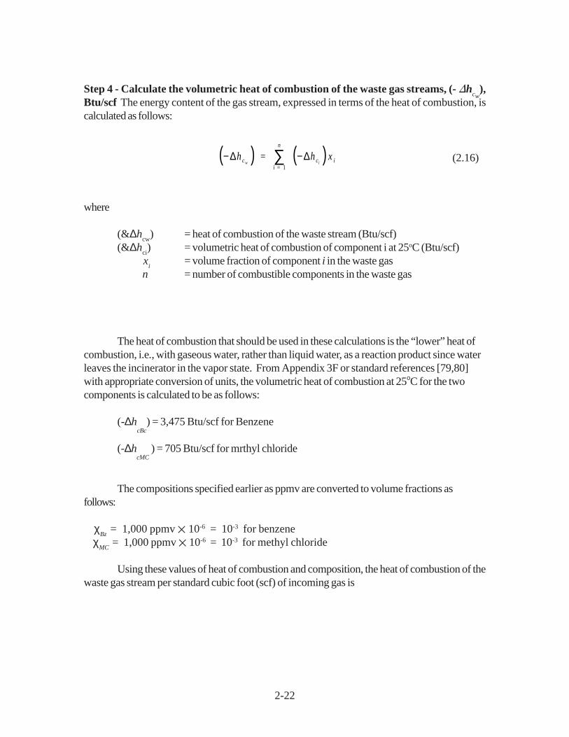
Step 4 - Calculate the volumetric heat of combustion of the waste gas streams, (- �hcw
),Btu/scf The energy content of the gas stream, expressed in terms of the heat of combustion, iscalculated as follows:
( ) ( )− −∑∆ ∆h h xc ci
n
iw i =
= 1(2.16)
where
(&∆hcw
) = heat of combustion of the waste stream (Btu/scf)(&∆h
ci) = volumetric heat of combustion of component i at 25oC (Btu/scf)
xi
= volume fraction of component i in the waste gas n = number of combustible components in the waste gas
The heat of combustion that should be used in these calculations is the “lower” heat ofcombustion, i.e., with gaseous water, rather than liquid water, as a reaction product since waterleaves the incinerator in the vapor state. From Appendix 3F or standard references [79,80]with appropriate conversion of units, the volumetric heat of combustion at 25οC for the twocomponents is calculated to be as follows:
(-∆hcBc
) = 3,475 Btu/scf for Benzene
(-∆hcMC
) = 705 Btu/scf for mrthyl chloride
The compositions specified earlier as ppmv are converted to volume fractions asfollows:
χBz
= 1,000 ppmv ✕ 10-6 = 10-3 for benzene χ
MC = 1,000 ppmv ✕ 10-6 = 10-3 for methyl chloride
Using these values of heat of combustion and composition, the heat of combustion of thewaste gas stream per standard cubic foot (scf) of incoming gas is

2-23
( ) ( ) ( ) ( ) ( )− = + =− −∆h c
B tu
scfw3 475 10 705 10 4 183 3, .
Assuming the waste gas is principally air, with a molecular weight of 28.97 and acorresponding density of 0.0739 lb/scf, the heat of combustion per pound of incoming waste gasis:
(−∆hcw
) = 56.6 Btu/lb
The negative heat of combustion, by convention, denotes an exothermic reaction. Also byconvention, if one refers to heat of reaction rather than heat of combustion, then a positive valuedenotes an exothermic reaction.
Empirically, it has been found that 50 Btu/scf roughly corresponds to the LEL of organic/air mixtures. Insurance codes require a value below 25% LEL, which corresponds to about 13Btu/scf. However, if LEL sensors and monitors are installed, one can incinerate a waste gas witha combustible organic content between 25 and 50% LEL, which corresponds to 13 to 25 Btu/scf.
For catalytic applications the heat of combustion must normally be less than 10 Btu/scf(for VOCs in air) to avoid excessively high temperatures in the catalyst bed. This is, of course,only an approximate guideline and may vary from system to system.
After Step 4, determination of the (-�hcw
) design procedure for thermal and catalyticincinerators is discussed separately, beginning with Step 5 for each type of incinerator.
2.4.2 Steps Specific to Thermal Units
Figure 2.1 shows a generic thermal incinerator with the appropriate streams labeled.
Step 5t - Establish the temperature at which the incinerator will operate As mentioned inSection 2.2.1, both the reactor temperature and residence time of the waste gas in the reactordetermine the level of VOC destruction. In general, state and local regulations specify the requiredlevel of destruction that the customer must meet. In this example a destruction efficiency of 98 %is specified. Studies by Mascone [2,3,4] show that this destruction efficiency can be met in athermal incinerator operated at a temperature, T
fi , of 1600oF and a residence time of 0.75 second.
(Note: This higher efficiency level is the minimum achievable by any new properly designed andoperated incinerator. Many incinerators can achieve destruction efficiencies of 99% or higher.)

2-24
Step 6t - Calculate the waste gas temperature at the exit of the preheater The extent of theheat exchange to be carried out in the preheater is the result of a technical and economic optimizationprocedure that is not illustrated in this example. As the VOC stream temperature leaving the heatexchanger, T
wo, increases, the auxiliary fuel requirement decreases, but at the expense of a larger
heat exchanger. However, there are several important limits on Two
. First, Two
must not be closeto the ignition temperature of the organic-containing gas to prevent damaging temperature excursionsinside the heat exchanger should the gas ignite. Second, for gases containing halogens, sulfur, andphosphorous (or other acid-forming atoms), the flue gas temperature after the heat exchanger, T
fo,
must not drop below the acid dew point. Both limitations limit the amount of heat exchange andthus the maximum value of T
wo. The calculation of the acid dew point is not simple. It is
recommended that vendor guidance be sought to ensure that the dew point is not reached.Condensation of acid gases will result in corrosion of many of the metals used in heat exchangers.As an example, fuel sulfur contents of 1 to 2 percent can give acid dew points of about 200 to270oF. Increasing the sulfur content to 4 percent can raise the dew to about 290oF. Chlorine andphosphorous have a much smaller effect on acid dew elevation.
With the following assumptions, one can estimate Two
using Equation 2.2, the definition offractional energy recovery for a heat exchanger:
• The fractional energy recovery is specified.
• The amount of auxiliary fuel, Qaf, and auxiliary combustion air, Q
a, are small relative to the
waste gas, Qw, so that the mass flow rates of gases, p
wQ
w and p
fQ
f, on both sides of the
preheater are approximately the same, or:
ρ ρw w fQ Q = f (2.17)
• The heat capacities of the gases on both sides of the preheater are approximately thesame, regardless of composition. This is true for waste streams which are dilute mixturesof organics in air, the properties of the streams changing only slightly on combustion.
• The mean heat capacities above the reference temperature of the gases on both sides ofthe preheater are approximately the same regardless of temperature.
With these assumptions, the equation for fractional energy recovery for a heat exchanger becomes:
F ractiona l E nery R ecovery = T - T
T Tw w
f w
o i
i i−
2-25
For this example with a fractional energy recovery of 0.70, an incinerator operatingtemperature, T
fi, of 1600oF, and a waste gas inlet temperature, T
wi, of 100oF, the waste gas
temperature at the end of the preheater becomes:
Two
= 1,150oF (2.18)
The temperature of the exhaust gas, Tfo
, can be determined by an energy balance on thepreheater, which, with the same assumptions as used in deriving Equation 2.18 regarding the massflow rates and average heat capacities of the gases involved, results in the following equation:
T - T = T - Tf f w wi o o i(2.19)
e.g., the temperature rise in the waste gas is approximately equal to the temperature decrease inthe flue gas with which it is exchanged. For this example, this results in
Tfo = 550
oF (2.20)
This value of Tfo
should be well above the acid dew point of the flue gas stream.
It should be remembered that Two
should be well below the ignition temperature of theVOC stream to prevent unwanted temperature excursions in the preheater. This must be verifiedeven if the stream is well below the LEL because flammability limits can be expanded by raising thereactant stream temperature. A sufficiently high preheat temperature, T
wo, could initiate reaction
(with heat release) in the preheater. This would ordinarily be detrimental to the materials ofconstruction in the heat exchanger. The one exception is the thermal incinerator of the regenerabletype described in Section 2.1 The 95-percent energy recovery, obtainable in regenerable systemswould result in this example in a T
wo of 1,525oF. The significant reaction rate that would occur at
this temperature in the ceramic packing of the heat exchanger/reactor is by design.
Step 7t - Calculate the auxiliary fuel requirement, Qaf Auxiliary fuel will almost invariably beneeded for startup of the unit. However, at steady state, if the energy released by combustion ofthe organics present in the waste stream is sufficient to maintain the reactor temperature (1600oFin the example), only a small amount of auxiliary fuel (< 5% of the total energy input) is needed tostabilize the flame. In most cases, however, more fuel than just this stabilizing fuel will be requiredto maintain the reactor temperature.
With the following assumptions, one can estimate Qaf
using a mass and energy balancearound the combustion chamber and following the principles discussed in Section 2.2, with referenceto Figure 2.1.

2-26
• The reference temperature, Tref
, is taken as the inlet temperature of the auxiliary fuel, Taf .
• No auxiliary air, Qa, is required.
• Energy losses, HL, are assumed to be 10% of the total energy input to the incinerator
above ambient conditions.[16,17] Thus, if the reference temperature is near ambientconditions,
( )H Q C T - TL fi fi pm fi reffi= 0 1. ρ (2.20)
• The heat capacities of the waste gases entering and leaving the combustion chamber areapproximately the same, regardless of composition. This is true for waste streams whichare dilute mixtures of organics in air, the properties of the streams changing only slightly oncombustion.
• The mean heat capacities above the reference temperature of the waste gases entering andleaving the combustion chamber are approximately the same regardless of temperature.Thus the mean heat capacity for the waste gas stream entering or leaving the combustionchamber should be evaluated at the average of T
wo and T
fi. For air this assumption
introduces an error of, at most, 5% over the temperatures of interest.
With these assumptions, the mass and energy balance around the combustion chamberreduces to the following equation:
( )T o ta l E nergy Inpu t = r Q C T - Tfi fi pm fi reffi(2.21)
Input data for this equation are summarized below:
The waste stream is essentially air so that
ρwo
= ρωι = 0.0739 lb/scf, air at 77oF, 1 atm
Cpmair
= 0.255Btu/lb F, the mean heat capacity of air between 77oF and 1375oF (the averagetemperature of the waste gas entering and leaving the combustion chamber)

2-27
Other input data to Equation 2.21 include:
Qwo
= Qwi
= 20,000 scfm(&∆h
caf) = 21,502 Btu/lb, for methane
Taf
= Tref
= 77oF, assume ambient conditions ρ
af= 0.0408 lb/ft
3, methane at 77oF
Tfi
= 1,600oF, Step 5t T
wo= 1,150oF, Step 6t
(&∆hcwo
) = 56.6 Btu/lb, Step 4
Substituting the above values into Equation 2.21 results in:
Qaf = 167 scfm (2.21a)
The values of the parameters in the energy balance are summarized in Table 2.5.
It is instructive to examine the magnitude of the various terms in the energy balance aroundthe combustor for the sample problem. This is done in Table 2.6. The energy balance shown doesnot quite add to zero due to round-off-error and simplifying assumptions. Table 2.6 shows that thelargest inlet term is the sensible heat of the incoming waste gas. The heat of combustion of theorganics contained in the waste gas stream is somewhat smaller than that of the auxiliary methanebecause of the relatively small amount of organics in the waste gas stream. The largest term in theoutlet stream is the sensible heat of the outgoing waste stream. The overall energy losses arebased on an assumption, but are relatively small. Because the sensible heat contents of the enteringand leaving waste stream are so large, it is apparent that energy recovery is an important factor inachieving energy efficiency. In fact, with zero energy recovery in the sample problem, the auxiliaryfuel requirements would be 605 scfm, about four times the energy requirements based on 70%energy recovery.
Step 8t - Verify that the auxiliary fuel requirement is sufficient to stabilize the burnerflame Only a small amount of auxiliary fuel (< 5% of the total energy input) is needed to stabilizethe burner flame. In general, more fuel than just this stabilizing fuel will be required to maintain thereactor temperature. It is wise to verify that the auxiliary fuel requirement calculated in Step 7t issufficient for stabilization. If it is insufficient, then a minimum amount of auxiliary fuel must be used,and the amount of energy recovery, specified earlier must be reduced to avoid exceeding thespecified temperature at which the incinerator will operate (Step 5t).
This check is made by calculating 5% of the total energy input to the incinerator andcomparing it with the auxiliary fuel energy input. The total energy input is given as follows:

2-28
0
Table 2.6: Terms in Energy Balance Around Combuster - Example Problem
Stream Subscript, j Value, Btu/min
IN Sensible Heat, ρj, Q
jC
pmj(T
i - T
ref)
Auxiliary Air a 0Waste Gas w
o404,403
OUT Sensible Heat, ρjQ
jC
pmj(T
i - T
ref)
Waste Stream fi
578,796
OUT Losses10% of total energy input 57,8800
GENERATIONHeat Combustion, ρ
jQ
j(-∆h
ef)
Waste Gas wo
83,655Auxiliary Fuel af 146,506
Table 2.5: Summary of Example Problem Variable Valuation T ref
= 77oF
Stream Subscript, j ρρρρρj, lb/scf Q
j, scfm C
pmj, Btu/lb oF T
j, oF
IN Sensible HeatAuxiliary Air a na na na naAuxiliary Fuel af 0.0408 167 1 77Waste Gas w
o0.0739 20,000 0.255 1,150
OUT Sensible HeatWaste Stream f
i0.0739 20,167 0.255 1,600
(-∆hc), waste gas = 56.6 Btu/lb
(-∆hc), auxiliary fuel = 21,502 Btu/lb
na = Not Applicable
1 = Not used becaused reference temperature is taken equal to auxiliary fuel temperature.

2-29
( )T o ta l E nergy Inpu t = r Q C T - Tfi fi pm fi reffi(2.22)
( )A uxiliary F uel E nergy Inpu t = r Q haf a f ca f-∆ (2.23)
The auxiliary fuel used in the design, Qaf
, should be the larger of 5% of the total energyinput (28,900 Btu/min.) and the auxiliary fuel energy input (146,500 Btu/min.). The auxiliary fuelused easily meets this criterion.
Step 9t - Calculate the total volumetric flow rate of gas through the incinerator, Qfi Thetotal volumetric flow rate of gas leaving the incinerator is referred to as the flue gas flow rate, Q
fi,
and is the gas rate on which the incinerator sizing and cost correlations are based. The flue gasflow rate measured at the standard conditions of 77oF and 1 atmosphere, where the increase involumetric throughput due to an increase in the number of moles of gas as a result of combustion isneglected, is the sum of the inlet streams to the incinerator.
Q Q Q Q
scfm
f w a afi o= + +
= + +
=
20 000 0 167
20 167
,
,(2.24)
This result conforms with the assumptions stated in Step 6t, e.g., the mass (and volume) flow rateson both sides of the preheater are approximately equal. Finally, it must be emphasized that steps5t to 9t apply to thermal recuperative incinerators only. To calculate the auxiliary fuel requirementsfor other types of thermal incinerators (e.g., regenerative), a different procedure must be used.(See Appendix B.)
2.4.3 Steps Specific to Catalytic Units
Figure 2.3 shows a generic catalytic incinerator with the appropriate streams labeled. Theapproach used in the calculations on the catalytic incinerator is somewhat different than that usedin the thermal incinerator. This difference arises because of additional constraints which are placed

2-30
on the catalytic incinerator. These constraints are as follows:
• The desired catalyst bed outlet temperature is typically 700 to 900oF. The maximumtemperature to which the catalyst bed can be exposed continuously is limited to about1200oF. Therefore, the combustible content of the waste gas is limited, and the amount ofheat exchange that occurs in the primary heat exchanger may be limited.
• The inlet temperature to the catalyst bed itself must be above the catalytic ignition temperaturerequired to give the desired destruction efficiency in the incinerator. Therefore, thecombustible content of the waste gas is further limited to that which, when combusted, willraise the temperature in the catalyst bed no more than the �T between the required reactorbed inlet temperature, and the desired reactor bed outlet temperature.
• Auxiliary fuel, in combination with the preheat from the primary heat exchanger, is used topreheat the waste gas to the reactor inlet temperature. A minimum amount of auxiliary fuel(< 5% of the total energy input) must be used to stabilize the flame in the preheat combustionchamber. This has the effect of further limiting the combustible content of the waste gasstream and the amount of heat exchange permissible in the primary heat exchanger.
The steps outlined below represent one approach to recognizing these constraints andincorporating them into the calculation procedures.
Step 5c - Establish the desired outlet temperature of the catalyst bed, Tfi The energy
released by the oxidation of the VOCs in the catalyst bed will raise the temperature of the gases byan amount, �T, as the gases pass through the catalyst bed. An outlet temperature from thecatalyst, and thus from the reactor, must be specified that will ensure the desired level of destructionof the VOC stream. As in thermal incinerators, this value varies from compound to compound andalso varies from catalyst to catalyst. Final design of the incinerator should be done by firms withexperience in incinerator design. Guidelines given by Combustion Engineering [12] indicate thatvalues from 300 to 900oF result in destruction efficiencies between 90 and 95 percent. To prevent
deactivation of the catalyst a maximum bed temperature of 1200oF should not be exceeded. In
the example problem the catalyst outlet temperature, Tfi, is selected to be 900oF.
Step 6c - Calculate the waste gas temperature at the exit of the preheater (primary) heatexchanger The waste gas temperature at the exit of the primary heat exchanger is estimated in thesame manner as for the thermal incinerator. The equation for fractional energy recovery Equation2.18, is used, with the same assumptions as used for the thermal incinerator. For the exampleproblem with a fractional energy recovery of 0.70, a catalyst bed outlet temperature, T
fi, of 900oF,
and a waste gas inlet temperature, Twi
, of 100oF, the gas temperature at the exit of the preheater

2-31
becomes
Two
= 660oF
The same considerations regarding the closeness of the temperature of the exhaust gas,T
fa, to its dew point apply to the catalytic incinerator as they did to the thermal incinerator.
Step 7c - Calculate the auxiliary fuel requirement, Qaf The auxiliary fuel requirement, Q
af, is
calculated by making mass and energy balances around the preheater combustion chamber andthe catalyst chamber. The auxiliary fuel requirement calculated in this manner must be checked toinsure that it falls within the constraints imposed by design considerations of the catalytic incinerator.These constraints are as follows:
• The auxiliary fuel requirement must be positive. A negative fuel requirement indicates thatthe heat of combustion of the waste gas, (-�h
c ), is too high for the fractional energy
recovery in the primary heat exchanger that was selected.
• The auxiliary fuel amount must be high enough to provide a stable flame in the preheatercombustion chamber (See Step 8c below).
An energy balance around the preheater combustion chamber and the catalyst chamber,taken together, results in Equation 2.21, the same equation used in the thermal incineratorcalculations. The input data for Equation 2.21 for the catalytic incinerator example problem aresummarized below:
• The waste stream is essentially air so that
�wo
= �wi
= 0.0739 lb/scf, air at 77oF, 1 atm
Cpmair
= 0.248 Btu/lb F, the mean heat capacity of air between 77oF and
780oF (the average of the preheater exit and catalyst bed outlettemperatures)
• Other input data to Equation 2.21 include:
Qwo
= Qwi
= 20,000 scfm

2-32
(&∆hcaf
) = 21,502 Btu/lb, for methaneT
af = T
ref= 77oF, assume ambient conditions
ρaf
= 0.0408 lb/ft3, methane at 77oF
Tfi
= 1,600oF, from Step 5c T
wo= 1,150oF, from Step 6c
(&∆hcwo
) = 56.6 Btu/lb, from Step 4
Substituting the above values into Equation 2.21 results in
Qaf = 40 scfm
If the outlet temperature of the catalyst bed, Tfi, is 800oF, then Q
af, decreases to -6.7
scfm. In other words, no auxiliary fuel would, theoretically, be required at this bed temperature.However, as discussed above in Step 8t, a certain quantity of auxiliary fuel would be required tomaintain burner stability.
At 70% energy recovery and 900oF outlet catalyst bed temperature, a waste gas with a
heat of combustion, (-�hcwo
), of about 79.9 Btu/lb would cause the auxiliary fuel requirement, Qaf
, to become negative, indicating the catalyst bed would exceed 900oF. At 70% energy recovery
and 800oF outlet catalyst bed temperature, this same result occurs with a (-�hcwo
) of 52.7 Btu/lb.Both of these heats of combustion are relatively low for typical waste gases. These results are, ofcourse, dependent on the assumption of energy losses from the combustion chamber. The lowerthe energy losses, the lower the allowable waste gas heat of combustion before overheating occursin the catalyst bed.
Step 8c - Verify that the auxiliary fuel requirement is sufficient to stabilize the burnerflame Only a small amount of auxiliary fuel (< 5% of the total energy input) is needed to stabilizethe burner flame. In general, more fuel than just this stabilizing fuel will be required to maintain thereactor temperature. It is wise to verify that the auxiliary fuel requirement calculated in Step 7c issufficient for stabilization. If it is insufficient, then a minimum amount of auxiliary fuel must be usedand the amount of energy recovery specified earlier must be reduced to avoid exceeding thespecified temperature at which the incinerator will operate (Step 5c).
This check is made in the same manner as that in Step 8t of the thermal incinerator calculation.The results of this check indicate that the auxiliary fuel requirement is more than sufficient to stabilizethe burner flame.

2-33
Step 9c - Estimate the inlet temperature to the catalyst bed, Tri The inlet temperature to the
catalyst bed must be calculated to ensure that the inlet temperature is above that necessary to ignitethe combustible organic compounds in the catalyst that was selected for use.
The inlet temperature to the catalyst bed, Tri
, should be such that, when the temperature
rise through the catalyst bed, T, is added to it, the resulting temperature is Tfi , 900oF. Thus,
∆T = T - Tf ri i(2.25)
The value of �T is determined by an energy balance around the preheater portion of thecombustor. The preheater is required to heat the gases up to the catalyst bed inlet temperatureusing auxiliary fuel.1 This energy balance is made with the assumptions made earlier in derivingEquation 2.21 and further assuming that only auxiliary fuel is combusted in the preheater portion.The resulting equation is very similar to Equation 2.21 except that (1) the terms with an f
i subscript
become terms with ri subscripts to denote a catalytic reactor inlet stream rather than a combustor
outlet (flue gas inlet to the primary heat exchanger) and (2) the term for combustion of the wastegas organics does not appear. The resulting equation is as follows:
( )[ ]( ) ( )
ρρ
a f a f
w w pm r w ref
c pm r ref
QQ C T - T - T
h C T - T
o o a ir i o
a f a ir i
=
-
1 1 0 1
1 1
. .
.− ∆(2.26)
This equation may be rearranged to solve for Tri explicitly. This produces an equation that
is somewhat complex and non-intuitive.
( )[ ] ( )( )T
Q h C T r Q C T T
C Q Qr
af a f c pm ref w w pm w ref
pm af a f w w
i
a f a ir o o a ir o
a ir o o
= + + +
+
ρ
ρ ρ
−∆ 1 1 0 1
1 1
. .
.(2.27)
After substituting the example problem parameters into Equation 2.27, we obtain a valuefor T
ri of 693oF. Based on ignition temperatures shown in Table 2.2, this reactor inlet temperature
should be satisfactory. Prior to a more definitive design, the ignition temperatures for the specificchemicals should be verified.
1 At equilibrium, the temperature of the catalyst bed is maintained without requiring auxiliary fuel.
2-34
The temperature rise across the catalyst bed is thus (900 - 693) or 207oF. Thesetemperatures are somewhat sensitive to the assumption for energy losses from the combustor. Theassumption for energy losses is perhaps somewhat conservative, i.e., it causes a larger Q
af to be
estimated than would a less conservative assumption, and becomes more conservative as thecombustor size and insulation are increased.
Step 10c - Calculate the total volumetric flow rate of gas through the incinerator, Qfi The
total volumetric flow rate of gas leaving the incinerator is referred to as the flue gas flow rate, Qfi,
and is the gas rate on which the incinerator sizing and cost correlations are based. The flue gasflow rate measured at the standard conditions of 77oF and 1 atmosphere, where the increase involumetric throughput due to an increase in the number of moles of gas as a result of combustion isneglected, is the sum of the inlet streams to the incinerator.
Qfi = Q
wo + Q
a + Q
af
= 20,000 + 0/40
= 20,040scfm
Step 11c - Calculate the volume of catalyst in the catalyst bed If the volumetric flow rate ofgas through the catalyst bed, Q
fi, and the nominal residence time (reciprocal space velocity) in the
catalyst bed are known, then the volume of catalyst can be estimated. There exists a complex setof relationships between the catalyst volume and geometry, overall pressure drop across the catalyst,conversion of the oxidizable components in the gas, gas temperature, and the reaction rate. Theserelationships are dependent on the catalyst and the type of compound being oxidized. It is beyondthe scope if this Manual to discuss these relationships, even in an approximate way. For thepurposes of cost estimation, the space velocity, in reciprocal time units, necessary to achieve therequired level of destruction can be used to approximate the catalyst volume requirement. Thespace velocity is defined as
φ = Q
Vft
ca t(2.28)
whereV
cat= Overall bulk volume of the catalyst bed, including interparticle voids (ft3)
By petro-chemical industry convention, the space velocity is computed at the conditionsof 60oF (not 77oF) and 1 atm. The volumetric flow rate, Q
fi , must be corrected to these conditions.
The proper space velocity to achieve a desired level of conversion is based on experimental datafor the system involved. For precious metal monolithic catalysts, the space velocity generally lies

2-35
between 10,000 h-1 and 60,000 h-1. (Base metal catalysts operate at lower space velocities,
ranging from 5,000 to 15,000 h-1.)[75]
There are a number of catalyst bed parameters, such as catalyst configuration and beddesign, that are not significant for study type cost estimates. Accordingly, design of these factorsis not discussed here.
2.5 Cost Analysis
This section presents procedures and data for estimating capital and annual costs for fourtypes of incinerators:(1) thermal-recuperative, (2) thermal regenerative, (3) fixed-bed catalytic,and (4) fluid-bed catalytic.
2.5.1 Estimating Total Capital Investment
Total capital investment, (TCI), includes the equipment cost, EC, for the incinerator itself,the cost of auxiliary equipment (e.g., ductwork), all direct and indirect installation costs, and costsfor buildings, site preparation, offsite facilities, land, and working capital. However, the last fivecosts usually do not apply to incinerators. (See Section 1of this Manual for a detailed descriptionof the elements comprising the TCI.) Although industry representatives were reluctant to provideupdated costs in 1999 dollars, they did indicate costs have not significantly changed since 1988[18,19,20]. In addition, SAIC obtained 11 vendor quotes for a specific configuration for threetypes of incinerator systems (recuperative, regenerative, fixed-bed catalytic). These quotescompared favorably to those generated from the cost equations.
2.5.1.1 Equipment Costs, EC
As discussed in Section 2.2.3, the EC given in this chapter apply to packaged incinerators,except for regenerative incinerators. For regenerative incinerators, the costs apply to field-erectedunits. The EC typically includes all flange-to-flange equipment needed to oxidize the waste gas,including the auxiliary burners, combustion chamber, catalyst, primary heat exchanger (except forthe “zero heat recovery” cases), weathertight housing and insulation, fan, flow and temperaturecontrol systems, a short stack, and structural supports. Smaller units, e.g., typically less than20,000 scfm, are typically preassembled skid-mounted [21]. The various available incinerationsystems are presented in four groups delineated according to their similarity of design. Thesegroups are outlined in Table 2.7. With the exception of regenerative thermal and fluid-bed catalyticincinerators, the maximum size for which costs are given is 50,000 scfm. Although larger units ofeach technology can be built, applications are rare at flow rates above 50,000 scfm. Regenerativethermal incinerator costs are provided for flow rates from 10,000 to 100,000 scfm. Fluid-bed

2-36
catalytic incinerator costs are provided for flow rates from 2,000 to 25,000 scfm.
The cost curves are least-squares regressions of cost data provided by different vendors. Itmust be kept in mind that even for a given incineration technology, design and manufacturingprocedures vary from vendor to vendor, so that costs may vary. As always, once the studyestimate is completed, it is recommended that more than one vendor be solicited for a more
Table 2.7: Scope of Cost Correlations
Incinerator Type Total (Flue) Gas Figure NumberFlowrate, scfm
Thermal – Recuperative 500a – 50,000 3.26Thermal – Regenerative 10,000 – 100,000 3.27Fixed-Bed Catalytic 2,000 – 50,000 3.28Fluid-Bed Catalytic 2,000 – 25,000 3.29a Although Figure 3.26 covers the 1,000 to 50,000 scfm range, the correlation is valid for the
500 to 50,000 scfm range.
detailed cost estimate.
The additional expense of acid gas clean-up or particulate control is not treated in thissection. The equipment cost of a gas absorber to remove any acid gases formed in the incineratorcan be quite large, sometimes exceeding the equipment cost of the incinerator itself even for simplepacked tower scrubbers [22]. For more complex absorbers that include venturi scrubbers insteadof, or in addition to, packed beds, the cost of the scrubber alone may be up to 4 times that of theincinerator [11]. These more complex absorbers are sometimes necessary when particulates, inaddition to acid gases, must be removed from the flue gas.
Thermal Incinerators Among the thermal units, the direct flame (0% energy recovery) andrecuperative systems are treated together because the various levels of energy recovery are achievedsimply by adding heat exchanger surface area. Costs for these units were provided by severalvendors [12,23,24]. The EC of these units are given as a function of total volumetric throughput,Q
tot, in scfm. “Q
tot”, is the total volume of the gaseous compounds exiting the combustion chamber;
it is identical to the term, “Qfi,” used in Figures 2.1 and 2.2. This includes the combustion products,
nitrogen, unburned fuel and organics, and other constituents. (See Figure 2.4). Note that costsare given free on board (F.O.B.) in April 1988 dollars12. Based on a least-squares regressionanalysis, a log-log relationship between throughput and EC was found for a given level of energy

2-37
12 For information on escalating these and the other incinerator prices to more current dollars, refer to theEPA report Escalation Indexes for Air Pollution Control Costs and updates thereto, all of which areinstalled on the OAQPS Technology Transfer Network (CTC Bulletin Board).
10,000
100,000
1,000,000
1,000 10,000 100,000
Flue Gas Volumetric Flow Rate, SCFM
Equ
ipm
ent C
ost,
FO
B, 1
999
Dol
lars
0% Energy Recovery
35% " "
50% " "
70% " "
recovery (HR) over the flow rate range from 500 to 50,000 scfm. These relationships are asfollows:
E C Q H Rtot. = = 10 294 0%0 235 5, (2.29)
E C Q H Rtot = = 13 149 35%0 260 9, . (2.30)
E C Q H Rtot. = = 1 7056 50%0 2502, (2.31)
E C Q H Rtot = = 21 342 70%0 250 0, . (2.32)
The regenerative (or excess enthalpy) systems provide up to 95 percent heat recovery atthe expense of higher capital costs. Their unique design [25,26], which combines the heat exchangerand reactor, is substantially different from traditional thermal units and is therefore treated separatelyin Figure 2.5. The ECs of these systems are given as an approximately linear function of total flowrate over a 10,000 to 100,000 scfm range by the following equation:
Figure 2.4: Equipment Costs of Thermal Incinerators, Recuperative

2-38
E C Q tot = + 2 204 10 11 575. .× (2.33)
Again, the higher capital costs of these units can be substantially offset by the substantialsavings in auxiliary fuel costs.
Catalytic Incinerator The EC for a catalytic incinerator is a function of the type of catalystcontacting pattern used and the total gas flow rate, Q
tot, for a given level of energy recovery. There
are three types of contacting configurations used in catalytic systems: fixed-bed, catalytic monolith,and fluid-bed. The EC for the first two are generally comparable and are given in Figure 2.6. Thedata provided by several vendors [12,23,24,27] exhibited curvilinear relationships with Q
tot for
each of the energy recovery rates. Least squares regressions of the data yielded the followingcorrelations for total flow rates between 2,000 and 50,000 scfm:
E C Q H Rtot = = 1105 0%0 547 1. (2.34)
E C Q H Rtot= = 3623 35%0 4189. (2.35)
E C Q H Rtot = = 1215 50%0 557 5. (2.36)
E C Q H Rtot = = 1443 70%0 552 7. (2.37)
Fluid-bed catalytic incinerators afford certain advantages over fixed-bed catalyst units inthat they tolerate waste streams with (1) higher heating values, (2) particulate contents, and (3)chlorinated species. For this enhanced flexibility of feed streams, a higher capital cost is incurred,
Figure 2.5: Equipment Costs of Thermal Incinerators, Regenerative
040
0,00
080
0,00
01,
200,
000
0 20,000 40,000 60,000 80,000 100,000 120,000
Flue Gas Volumetric Flow Rate, SCFM
Equ
ipm
ent C
ost,
FO
B, 1
999
Dol
lars
95% Energy Recovery

2-39
Figure 2.6: Equipment Cost of Catalytic Incinerators, Fixed-Bed
10,000
100,000
1,000,000
1,000 10,000 100,000
Flue Gas Volumetric Flow Rate, SCFM
Equ
ipm
ent C
ost,
FO
B, 1
999
Dol
lars
0% Energy Recovery
35% " "50% " "
70% " "
Figure 2.7: Equipment Costs of Catalytic Incinerators, Fluid-Bed
020
0,00
040
0,00
060
0,00
080
0,00
0
0 10,000 20,000 30,000 40,000 50,000
Flue Gas Volumetric Rate, SCFM
Equ
ipm
ent C
ost,
FO
B, 1
999
Dol
lars
0% Energy Recovery35% " "50% " "70% " "

2-40
Figure 2.8: Equipment Costs Comparison of Incinerator Types
10,000
100,000
1,000,000
1,000 10,000 100,000
Flue Gas Volumetric Flow Rate, SCFM
Equ
ipm
ent C
ost,
FO
B, 1
999
Dol
lars
Catalytic - Fluid Bed
Catalytic - Fixed Bed
Thermal - Recup
50% Energy Recovery
as indicated by the EC shown in Figure 2.7. The data shown were provided by vendors [1,22]and exhibited a linear relationship over the range of flow rates from 2,000 to 25,000 scfm. Theycan be approximated by the following equations:
E C . Q H Rtot = + = 8 48 10 13 2 0%4. × (2.38)
E C Q H Rtot = + = 8 84 10 14 6 35%4. .× (2.39)
E C Q H Rtot = + = 8 66 10 15 8 50%4. .× (2.40)
E C Q H Rtot = + = 8 39 10 19 2 70%4. .× (2.41)
A comparison of the thermal, catalytic fixed-bed, and catalytic fluid-bed systems with 50percent energy recovery is shown in Figure 2.8.
2.5.1.2 Installation Costs
As explained in Section 1, the purchased equipment cost, PEC, is calculated by taking the

2-41
sum of the EC and the cost of auxiliary equipment (e.g., ductwork), taxes, freight, and instrumentation.Average values of direct and indirect installation factors [31] to be applied to the PEC are given inTable 2.8 for both recuperative thermal and fixed- and fluid-bed catalytic incinerators.
Table 2.9 shows the itemized installation costs that are obtained when these installation factors areapplied to the PECs for the example incinerators. Depending on the site conditions, the installationcosts for a given incinerator could deviate significantly from costs generated by these averagefactors. Vatavuk and Neveril [31] provide some guidelines for adjusting the average installationfactors to account for other-than-average installation conditions. For units handling total gas flowrates lower than 20,000 scfm the installation costs are minimal, amounting normally to only utilitytie-ins (electrical and, if necessary, combustion or dilution air). The installation costs for thesesmaller incinerators would be 20 to 25% of the PEC. Smaller units may be installed on the roofsof manufacturing buildings rather than at ground level. In such cases the installation factors couldbe as high as (or higher than) the factors shown in Table 2.8, even though the units would be“packaged.”
2.5.2 Estimating Total Annual Cost
The total annual cost (TAC) is the sum of the direct and indirect annual costs. The TAC for bothexample systems is given in Table 2.10, alone with suggested factors for calculating them.
2.5.2.1 Direct Annual Costs
Direct annual costs for incinerators include labor (operating and supervisory), maintenance(labor and materials), fuel, electricity, and (in catalytic units) replacement catalyst. For thermal andcatalytic units, the fuel usage rate is calculated as shown in Sections 2.3.2 and 2.3.3, respectivelywhere natural gas (methane) is assumed to be the fuel. (Other fuels could be used for thermalunits.)
The electricity costs are primarily associated with the fan needed to move the gas throughthe incinerator. The power (in kilowatts) needed to move a given inlet volumetric flow rate of air(Q
wi per Sections 2.2.3 and 2.3.3) at a total flange-to-flange pressure drop of �P inches of water
and combined motor/fan efficiency, � , is adapted from Equation 2.7, as follows:
P ow er Q P
fan
w i= 1 17 10 4. × − ∆
ε(2.42)
Fan efficiencies vary from 40 to 70 percent [31] while motor efficiencies are usually 90 percent.
The total pressure drop across an incinerator system depends on the number and types of

2-42
Table 2.8: Capital Cost Factors for Thermal and Catalytic Incinerators [10]
Cost Item Factor
Direct CostsPurchased equipment costs
Incinerator (EC) + auxiliary equipmenta As estimated, AInstrumentationb 0.10 ASales taxes 0.03 AFreight 0.05 A
Purchased equipment cost, PEC B = 1.18 A
Direct installation costsFoundations & supports 0.08 BHandling & erection 0.14 BElectrical 0.04 BPiping 0.02 BInsulation for ductworkc 0.01 BPainting 0.01 B
Direct installatoin costs 0.03 B
Site preparation As required, SPBuildings As required, Bldg.
Total Direct Costs, DC 1.30 B + SP + Bldg.
Indirect Costs (installation)Engineering 0.10 BConstruction and field expenses 0.05 BContractor fees 0.10 BStart-up 0.02 BPerformance test 0.01 BContingencies 0.03 B
Total Indirect Costs, IC 0.31 B
Total Capital Investment = DC + IC 1.61 B + SP + Bldg.
a Ductwork and any other equipment normally not included with unit furnished by incinerator vendor.b Instrumentation and controls often furnished with the incinerator, and those often included in the EC.c If ductwork dimensions have been established, cost may be estimated based on $10 to $12/ft2 of surface for fluid application. (Alternatively, refer to Section 1.2 of this Manual. Fan housing and stacks may also be insulated.
2-43
equipment elements included in the system and on design considerations. The estimation of actualpressure drop requirements involves complex calculations based on the specific system’s wastegas and flue gas conditions and equipment used. For the purposes of this section, however, theapproximate values shown in Table 2.11 can be used.
For the example cases, we will assume 8,000 hours per year operation and a 60% efficiencyfor the fan and motor together. Using pressure drops of 4 and 8 inches of water, respectively, forthe thermal and fluid-bed catalytic incinerators, 3 and adding the pressure drop of 15 inches ofwater for 70% heat recovery, the fan power requirements can be calculated as follows:
Thermal Incinerator4
( ) ( )P ow er
acfm inches w a terkWfan =
=
1 17 10 20 900 19
0 6077 4
4. ,
..
× −
Catalytic Incinerator
( ) ( )P ow er
acfm inches w a ter. kWfan =
=
1 17 10 20 900 23
0 6093 7
4. ,
.
× −
The annual electricity costs would be the products of these usages, the annual operatinghours, and the electricity cost ($/kWh), or:
Electricity Cost (Thermal) = 77.4 kW × 8,000 hours/yr × $0.059/kWh= $36,500 per yr
Electricty Cost (Catalytic) = 93.7 kW × 8,000 hours/yr × $0.059/kWh= $44,200 per yr
The catalyst replacement costs and scheduling are highly variable and depend on thenature of the catalyst, the amount of “poisons” and particulates in the gas stream (including theauxiliary fuel), the temperature history of the catalyst, and the design of the unit. It is impossible topredict the costs in a general sense. However, noble metal monolith catalysts operating on purehydrocarbon gases in air will last longer than fluid-bed base metal catalysts operating on chlorinatedhydrocarbons in air. Noble metal catalysts are also more expensive than base metal oxide catalysts.The catalyst life for many field units is from 1 to 4 years. The cost, in April 1988 dollars, of the

2-44
Table 2.9: Capital Cost Factors for Thermal and Catalytic Incinerator [10]Example Problems
Cost Item Cost, $Thermal-Recuperative Fluid-Bed
Catalytic
Direct CostsPurchased equipment costs
Incinerator (EC) $254,200 $468,000Auxiliary equipment - -
Sum = A 254,000 468,000
Instrumentation, 0.1Aa 25,400 46,800Sales taxes, 0.30 A 7,630 14,000Freight. 0.05 A 12,700 13,400
Purchased equipment cost, B $300,000 $552,400
Direct installation costsFoundations & supports, 0.08 B 24,000 44,200Handling & erection, 0.14 B 42,000 77,300Electrical, 0.04 B 12,000 22,100Piping, .002 B 6,000 11,000Insulation for ductwork, 0.01B 3,000 5,520Painting, 0.01 B 3,000 5,520
Direct installation costs $90,000 $165,000
Site preparationa - -Buildingsa - -
Total Direct $390,000 $718,000
Indirect Costs (installation)Engineering, .010 B 30,000 55,200Construction and field expenses, 0.05 B 15,000 27,600Contractor fees, 0.10 B 30,000 55,200Start-up, 0.02 B 6,000 11,000Performance test, 0.01 B 3,000 5,520Contingencies, 0.03 B 9,000 16,600
Total Indirect Costs $93,000 $171,100
Total Capital Investment (rounded) $483,000 $889,000
a None of these items is required.

2-45
Table 2.10: Annual Costs for Thermal and Catalytic IncineratorsExample Problem
Cost Item Suggested Factor Unit Costa Thermal Fluid-BedCatalyst
Direct Annual Costsb, DCOperating Labor Operator 0.5 hr/shift $12.95/hr. 6,480 6,480 Supervisor 15% of operator - 972 972Operating Materials -
Maintenance Labor 0.5 hr/shift $14.95/hr. 7,130 7,130 Materials 100% of maintenance labor - 7,130 7,130
Catalyst replacement 100% of catalyst replaced $650/ft3 for 0 15,100metal oxide
Utilities Natural Gas - $3.30/kft3 264,500 63,400 Electricity - $0059/kWh 36,500 44,200
Total DC $321,200 $144,400
Indirect Annual Cost, ICOverhead 60% of sum of operating, - 13,000 17,800
supervisor, & maintenancelabor & maintenance materials
Administrative Charges 2% TCI - 9,650 17,800Property Taxes 1% TCI - 4,830 8,900Insurance 1% TCI - 4,830 122,700Capital recoveryc CRF [TCI - 1.08 (cat. Cost)] - 68,800 122,700
$101,100 $171,300
Total Direct Cost (rounded) $422,000 $316,000
a 1998 dollarsb Assumes 8,000 hr/yrc The capital recovery cost factor, CRF, is a function of the catalyst or equipment life (typically, 2 and 10 years, respectively) and the opportunity cost of the capital (i.e., interest rate). For example, for a 10-year equipment life
and a 7% interest rate, CRF = 0.1424

2-46
3 A fluid-bed catalytic incinerator is used because the waste gas contains a chlorinated compound which would poison the catalyst
in a fixed-bed incinerator.4 Computed from inlet waste-gas flow rate (20,000 scfm) at preheater inlet temperature (100oF).
replacement catalyst must be obtained from the vendor, but it may be estimated at $3,000/ft3 for
noble metal catalysts and $650/ft3 for base metal oxide catalysts. For the example case, thecatalyst is a base metal oxide because the waste gas contains a chlorinated compound. We willassume a two year catalyst life. Knowing that the catalyst volume is 39 ft3 and using a cost of
$650/ft3 and a capital recovery factor of 0.5531 (2-year life at a 7% interest rate), the annualexpense for catalyst replacement is
( ) ( )P ow er
acfm inches w a ter. kWfan =
=
1 17 10 20 900 23
0 6093 7
4. ,
.
× −
(The “ 1.08” factor covers the freight and sales tax for the replacement catalyst.)
To calculate the fuel or electricity annual cost, multiply the fuel usage rate (scfm) or theelectricity usage rate (kW) by the total hours per year of operation (e.g., 333 d/yr x 24 h/d =8,000 h/yr) and by the appropriate unit cost (e.g., $/scfm for fuel and $/kWh for electricity).
For the example cases, the fuel costs can be calculated from the fuel usage rates and thenatural gas unit cost of $0.00330/scf. For the thermal incinerator example, the annual fuel cost iscalculated as follows:
Annual Fuel = 0.00330 $/scf × 167 scf/min × 60 min/hr × 8,000 hr/yr
Table 2.11: Typical Pressure Drop Across Selected Equipment
Equipment Type Energy Recovery, % ∆ ∆ ∆ ∆ ∆P, in. H2O
Thermal Incinerators 0 4Catalytic Fixed-bed Incinerator 0 6Catalytic Fluid-bed Incinerator 0 6-10Heat Exchangers 35 4Heat Exchangers 50 8Heat Exchangers 70 15

2-47
Cost, Thermal = $264,500 per year
For the catalytic incinerator example. the annual fuel cost is found similarly:
Annual Fuel Cost, Catalytic = $63,400 per year
Operating and maintenance labor are estimated as 0.5 hours per 8-hour shift each,supervisory labor at 15% of operating labor, and maintenance material as 100% of maintenancelabor.
2.5.2.2 Indirect Annual Costs
The indirect (fixed) annual costs include capital recovery, overhead, and property taxes, insurance,and administrative (G&A) charges. The last three of these can be estimated at 1%, 1%, and 2%of the total capital investment, respectively. The system capital recovery cost is based on anestimated 10-year equipment life. (See Section 1.2 for a thorough discussion of the capital recoverycost and the variables that determine it.) The system capital recovery cost is the product of thesystem capital recovery factor (CRF) and the total capital investment (TCI) less the purchasedcost of the catalyst (C
cat x 1.08 where the 1.08 is for freight and sales tax). These values calculated
for the example cases are given in Table 2.47.
2.5.3 Cost Comparison for Example Case
The example VOC stream defined in Section 2.2.4.1 serves to illustrate some typical characteristicsof thermal and catalytic systems. The total annual costs shown in Table 2.47 show that the catalyticsystem’s auxiliary fuel costs are significantly lower than those of the thermal unit. The disparity isenough to offset the higher capital costs of the catalytic incinerator over the assumed 10-yearlifetime of the units. Two factors that should be noted in the comparison of these two systems are(1) the 98 percent level of destruction met by the thermal incinerator may be difficult to reach bythe catalytic system (this may be important in some cases), and (2) the example waste stream is ofparticularly low heating value (4 Btu/scf) which favors the catalytic system due to the lower auxiliaryfuel requirements.
2-48
2.6 Acknowledgements
The authors gratefully acknowledge the following companies for contributing data to thischapter:
• Peabody Engineering (Stamford, CT)
• Combustion Engineering - Air Preheater, Inc. (Wellsville, NY)
• TEC Systems, Inc. (DePere, WI)
• Air Research, Inc. (ARI) (Palatine, IL)
• Energy Development Associates (EDA) (Itasca, IL)
• Pillar Technologies, Inc. (Hartland, WI)
• Huntington Energy Systems, Inc. (Union, NJ)
• Regenerative Environmental Equipment Co. (REECO) (Morris Plains, NJ)
• Englehard Corp. (Edison, NJ)

2-49
References
[1] Prudent Practices for Disposal of Chemicals from Laboratories, National AcademyPress,Washington, D.C., 1983.
[2] Memorandum from Mascone, D.C., EPA, OAQPS, to Farmer, J. R., OAQPS, EPA,June 11, 1980, Thermal Incinerator Performance for NSPS.
[3] Memorandum from Mascone, D.C., EPA, OAQPS, to Farmer, J. R., OAQPS, EPA,July 22, 1980, Thermal Incinerator Performance for NSPS, Addendum.
[4] Memorandum from Mascone, D.C., EPA, OAQPS, to Farmer, J. R., OAQPS, EPA,August 22, 1980, Thermal Incinerators and Flares.
[4] Letter from Thomas Schmidt (ARI International, Palatine, IL) to William M. Vatavuk(EPA, OAQPS, Research Triangle Park, NC), August 16, 1989.
[5] Weldon, J. and S. M. Senkan, Combustion Sci. Technol., 1986, 47.
[6] Manning, P., Hazard Waste, 1984, 1(1).
[7] Pope, D., Walker, D. S., Moss, R. L., Atmos. Environ., 1976, 10.
[8] Musick, J. K., and F. W. Williams, Ind. Eng. Chem. Prod. Res. Dev., 1974, 13(3).
[9] Letter from Robert M. Yarrington (Englehard Corporation, Edison, NJ) to William M.Vatavuk (EPA, OAQPS, Research Triangle Park, NC), August 14, 1989.
[10] Personal Communication from Bill Sheffer (ARI, Inc., Palatine, IL) to Donald R. van derVaart (RTI, Research Triangle Park, NC), March 30, 1988.
[11] Personal Communication from Ralph Stettenbenz (Combustion Engineering, Air Preheater,Inc., Wellsville, NY) to Donald R. van der Vaart (RTI, Research Triangle Park, NC),March 23, 1988.
[12] Grelecki, C., Fundamentals of Fire and Explosion Hazards Evaluation, AIChE TodaySeries, New York, 1976.
[13] Weast, R.C. (ed.), CRC Handbook of Chemistry and Physics, 49th ed., CRC Press,Cleveland, Ohio, 1968.
2-50
[14] Perry, R. H. and C. H. Chilton(eds.), Chemical Engineers Handbook, 5th ed., McGraw-Hill, New York, NY 1973.
[15] Personal Communication from Robert Yarrington (Englehard Corp., Edison, NJ) to WilliamM. Vatavuk (EPA, OAQPS, Research Triangle Park, NC), June 6, 1989.
[16] Personal communication from Gary Masonick (Goal Line Environmental Technolgies) toJanet D. Groeber (SAIC. Cincinnati, OH), September 29,1999.
[17] Personal communication from Gary Raemheld (Goenergy, Kent, WA) to Janet D. Groeber(SAIC. Cincinnati, OH), September 28,1999.
[18] Personal communication from John Wilke (CVM Corp., Wilmington, DE) to Janet D.Groeber (SAIC. Cincinnati, OH), September 29,1999.
[19] Personal Communication from Thomas Schmidt (ARI International, Palatine, IL) to WilliamM. Vatavuk (EPA, OAQPS, Research Triangle Park, NC), June 7, 1989.
[20] Githens, R. E. and D. M. Sowards, Catalytic Oxidation of Hydrocarbon Fumes, PB-299 132, National Technical Information Service, Springfield, VA.
[21] Personal Communication from Andrew Jones (Energy Development Associates, Itasca,IL) to Donald R. van der Vaart (RTI, Research Triangle Park, NC), March 4, 1988.
[22] Personal Communication from C. L. Bumford (Peabody Engineering, Stamford, CT) toDonald R. van der Vaart (RTI, Research Triangle Park, NC), March 28, 1988.
[23] Personal Communication from C. M. Martinson (TEC Systems, DePere, WI) to DonaldR. van der Vaart (RTI, Research Triangle Park, NC), March 28, 1988.
[24] Personal Communication from Ronald J. Renko (Huntington Energy Systems, Inc., Union,NJ) to Donald R. van der Vaart (RTI, Research Triangle Park, NC), March 16, 1988.
[25] Personal Communication from James H. Mueller (Regenerative Environmental EquipmentCo., Inc., Morris Plains, NJ) to Donald R. van der Vaart (RTI, Research Triangle Park,NC), January 13, 1988.
[26] Personal Communication from Robert Hablewitz (Pillar Technologies, Hartland, WI) toDonald R. van der Vaart (RTI, Research Triangle Park, NC), March 20, 1988.
[27] Kobe, K. A. and associates, “Thermochemistry for the Petrochemical Industry”, PetroleumRefiner, Jan. 1949 through Nov. 1954.

2-51
[28] Letter from William M. Vatavuk (EPA, OAQPS, Research Triangle Park, NC) to GeraldSchrubba (Salem Engelhard, South Lyon, MI), September 22, 1992.
[29] Letter from William M. Vatavuk (EPA, OAQPS, Research Triangle Park, NC) to RodPennington (REECO/Research Cottrell, Somerville, NJ), September 22, 1992.

2-52
Appendix A
Properties of Selected Compounds

2-53
Compound Molecular LELa UELb
Weight (volume %) (volume %)
Methane 16.04 5.00 15.00Ethane 30.07 3.00 12.50Propane 44.09 2.12 9.35Butane 58.12 1.86 8.41Pentane 72.15 1.40 7.80Hexane 86.17 1.18 7.40Octane 114.23 0.95Nonane 128.25 0.83Decane 142.28 0.77Ethylene 28.05 2.75 28.60Propylene 42.08 2.00 11.10Acetylene 26.04 2.50 80.00Cyclohexane 84.16 1.26 7.75Benzene 78.11 1.40 7.10Toluene 92.13 1.27 6.75
a Lower Explosive Limit b Upper Explosive Limit
Table 2.12: Limits of Flammability of Combustible Organic Compounds in Airat Atmospheric Pressure, Room Temperature [79]

2-54
Table 2.13: Molar Heat Capabilities of Gases at Zero Pressure [25]
Cp � a � bT � cT 2� dT 3 ; T in �K
Cpm �
�T2
T1
CpdT
(T2 � T1)
Cp in calories/g�moles oK Btu/lb�mole oR
Compound a b x 102 c x 106 d x 1010 TemperatureRange (°K)
Methane 4.750 1.200 0.3030 -2.630 273-1500Ethane 1.648 4.124 -1.530 1.740 273-1500Propane -0.966 7.279 -3.755 7.580 273-1500Butane 0.945 8.873 -4.380 8.360 273-1500Pentane 1.618 10.85 -5.365 10.10 273-1500Hexane 1.657 13.19 -6.844 13.78 273-1500Cyclopentane -12.957 13.087 -7.447 16.41 273-1500Cyclohexane -15.935 16.454 -9.203 19.27 273-1500Benzene -8.650 11.578 -7.540 18.54 273-1500Toluene -8.213 13.357 -8.230 19.20 273-1500Nitrogen 6.903 -0.037553 0.1930 -0.6861 273-1500Oxygen 6.085 0.3631 -0.1709 0.3133 273-1500Air 6.713 0.04697 0.1147 -0.4696 273-1500Carbon Dioxide 5.316 1.4285 -0.8362 1.784 273-1500

2-55
MolecularCompound Weight (cal/g) -∆hc (Btu per lb)
Methane 16.04 11,953.3 21,502Ethane 30.07 11,349.6 20,416Propane 44.09 11,079.2 19,929Butane 58.12 10,932.3 19,665Pentane 72.15 10,839.7 19,499Hexane 86.17 10,780.0 19,391Octane 114.23 10,737.2 19,256Nonane 128.25 10,680.0 19,211Decane 142.28 10,659.7 19,175
Ethylene 28.05 11,271.7 20,276Propylene 42.08 10,942.3 19,683
Acetylene 26.04 10,476.7 19,001Cyclohexane 84.16 9,698.4 19,846
Benzene 78.11 9,698.4 17,446Toluene 92.13 9,784.7 17,601
Table 2.14: Heats of Combustion of Selected Gaseous Organic Compounds [80]

2-56
Appendix B
Design Procedure for Non-RecuperativeThermal Incinerators

2-57
Not all thermal incinerators are equipped with recuperative heat exchangers to transferenergy from the flue gas stream to the incoming waste gas stream. These non-recuperative unitsuse other mechanisms to recovery flue gas energy. One of these types is the regenerative incinerator.As discussed in a subsection of Section 2.1 entitled Regenerative Incinerators, a regenerativeincinerator accomplishes energy recovery by conveying the flue gas through a ceramic bed whichcaptures a portion of the stream’s enthalpy. After a switching mechanism is engaged, the incomingwaste gas passes through this hot bed and is warmed to its ignition temperature. This process isillustrated in Figure 2.2.
While we can determine the stream inlet and outlet temperatures for a recuperative heatexchanger fairly accurately, we cannot always do so for a regenerative incinerator bed. For onething, these beds do not behave like typical heat exchangers. The bed temperature profiles areoften difficult to predict. More importantly, because regenerative incinerators do not operate atsteady state conditions, the temperatures within the beds and many other parts of the unit vary withtime. For that reason, it is more convenient to view the entire regenerative incinerator as a “blackbox” into which waste gas and auxiliary fuel flow and from which flue gas emanates. Around thisblack box we may make mass and energy balances. In this way, we need not make any assumptionsabout what occurs inside the incinerator regarding temperatures, flowrates, or other streamparameters.
However, to determine the auxiliary fuel requirement for regenerative incinerators via theprocedure shown in this appendix we have to make two key assumptions, viz.: (1) the temperaturesand flowrates of all streams entering and leaving the incinerator are at steady state and (2) thecombustion temperature (and by inference, the heat loss fraction) are constant as well. The otherassumptions will be addressed in the following design steps:
Steps 1 to 4: These are the same as those for thermal recuperative and catalytic incinerators.(See Section 2.4.1.)
Step 5t - Establish the incinerator operating temperature: Because their designs are moreresistant to thermal stresses and because they can achieve very high heat recoveries, regenerativeincinerators are usually operated at higher temperatures than recuperative units. Consequently,higher VOC destruction efficiencies are achieved. Operating temperatures of 1800 to 2000o Fare typical.
Step 6t - Calculate the waste gas temperature at the exit of the preheater: As explainedabove, regenerative incinerators do not employ preheaters. The preheating is done by and withinthe ceramic beds. Moreover, because the mass and energy balances are made around the entire

2-58
unit, we do not need to know the temperature of the preheated waste gas to calculate the auxiliaryfuel requirement.
Step 7t - Calculate the auxiliary fuel requirement, Qaf: Because a regenerative incineratorrecovers nearly all of the energy from the combustion (flue) gas, its auxiliary fuel requirement is
Flue Gas(fo)
Incinerator Unit(Any Type)
Waste Gas(wi)
Auxiliary Fuel(af)
usually lower than that for a recuperative incinerator. However, as discussed above, this fuelrequirement is determined via mass and energy balances taken around the entire unit, not just thecombustion chamber. Consider the following diagram:
Taking mass and energy balances around the incinerator, we obtain:
Mass balance:
Mass in = Mass out
Mass fuel + Mass waste gas = Mass flue gas
�
afQ
af + �
wiQ
wi = �
foQ
fo
Energy balance:
Next, we take an energy balance around the incinerator unit:
Energy in - Energy out + Energy generated = 0
The terms of the energy balance equation are the inlet waste gas and outlet flue gas enthalpies(H
wi and H
fo, respectively), the energy loss (H
L), and the waste gas VOC and fuel (natural gas)
heat contents (Hcwi
and Hcaf
, in turn):
Hwi
- (Hfo + H
L) + (H
cwi + H
caf) = 0

2-59
The variables comprising each of the terms in this energy balance equation are listed inTable2.6. They are:
Hwi
= �wi
Qwi
Cpmwi
(Twi
- Tref
)
Hfo
= �fo
Qfo
Cpmfo
(Tfo
- Tref
)
HL = ��
fiQ
fiC
pmfi(T
fi - T
ref)
Hcwi
= �wi
Qwi
(-�hcwi
)
Hcaf
= �af
Qaf
(-�hcaf
)
where
� = energy loss from combustion chamber (fractional)T
fi= combustion temperature (oF)
We next substitute these variables into Equation 2.51 and solve for the fuel mass rate(�
afQ
af). When doing so, we make the following assumptions:
• The streams flowing to and from the incinerator are at steady state conditions.
• The auxiliary air requirements are zero.
• The ambient, reference, and fuel inlet temperatures are equal (77oF). (This assumptionresults in the inlet fuel stream having a zero enthalpy.)
• The heat capacities of the gas streams to and from the unit are approximately the same,regardless of composition.
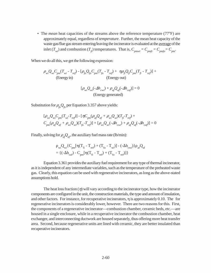
2-60
• The mean heat capacities of the streams above the reference temperature (77oF) areapproximately equal, regardless of temperature. Further, the mean heat capacity of thewaste gas/flue gas stream entering/leaving the incinerator is evaluated at the average of theinlet (T
wi) and combustion (T
fi) temperatures. That is, C
pmwi = C
pmfi = C
pmfo= C
pm.
When we do all this, we get the following expression:
�wi
Qwi
Cpm
(Twi
- Tref
) - [�fo
Qfo
Cpm
(Tfo
- Tref
) + ��fiQ
fiC
pm(T
fi - T
ref)] +
(Energy in) (Energy out)
[�wi
Qwi
(-�hcwi
) + �af
Qaf
(-�hcaf
)] = 0
(Energy generated)
Substitution for �fo
Qfo
per Equation 3.357 above yields:
[�wi
Qwi
Cpm
(Twi
-Tref
)] - [�Cpm
(�af
Qaf + �
wiQ
wi)(T
fi-T
ref) +
Cpm
(�af
Qaf + �
wiQ
wi)(T
fo-T
ref)] + [�
wiQ
wi(-�h
cwi) + �
afQ
af(-�h
caf)] = 0
Finally, solving for �afQ
af , the auxiliary fuel mass rate (lb/min):
�wi
Qwi
{Cpm
[�(Tfi - T
ref) + (T
fo - T
wi)] - (-�h
cwi)}�
afQ
af
= {(-�hcaf
) - Cpm
[�(Tfi - T
ref) + (T
fo - T
ref)]}
Equation 3.361 provides the auxiliary fuel requirement for any type of thermal incinerator,as it is independent of any intermediate variables, such as the temperature of the preheated wastegas. Clearly, this equation can be used with regenerative incinerators, as long as the above-statedassumptions hold.
The heat loss fraction (�) will vary according to the incinerator type, how the incineratorcomponents are configured in the unit, the construction materials, the type and amount of insulation,and other factors. For instance, for recuperative incinerators, � is approximately 0.10. The forregenerative incinerators is considerably lower, however. There are two reasons for this. First,the components of a regenerative incinerator—combustion chamber, ceramic beds, etc.—arehoused in a single enclosure, while in a recuperative incinerator the combustion chamber, heatexchanger, and interconnecting ductwork are housed separately, thus offering more heat transferarea. Second, because regenerative units are lined with ceramic, they are better insulated thanrecuperative incinerators.

2-61
To gain an estimate of this heat loss fraction, we contacted two regenerative incineratorvendors. [94,95] Based on the heat loss data that they supplied, we calculated values rangingfrom 0.002 to 0.015 (0.2 to 1.5%). These values varied according to the incinerator configuration(vertical or horizontal), the waste gas flow rate, the ambient temperature, and the wind speed.
Step 8t - Verify that the auxiliary fuel requirement is sufficient to stabilize the burnerflame: As explained in Section 2.4.2, only a small amount (< 5% of the total energy input) isneeded to stabilize the burner flame. With recuperative incinerators, the auxiliary fuel requirementis usually much larger than the burner stabilization requirement, so that this constraint rarely comesinto play. With regenerative incinerators, however, the auxiliary fuel requirement may be as low orlower than the fuel needed to stabilize the burner. Therefore, it is important to compare these tworequirements. This comparison is made via Equations 3.326 and 3.327. If the auxiliary fuel is less,the minimum fuel requirement would be set at 5% of the total energy input.
Step 9t - Calculate the flue gas volumetric flow rate, Qfi: As with thermal recuperativeincinerators, the regenerative incinerator flue gas flow rate is the rate used to size and cost the unit.Measured at standard conditions (1 atmosphere and 77oF), Q
fi is the sum of the inlet waste gas
(Qwi
) and fuel (Qaf
) flow rates. But since Qaf
for regenerative units is small compared to Qwi
, thewaste gas and flue gas flows should be virtually identical.
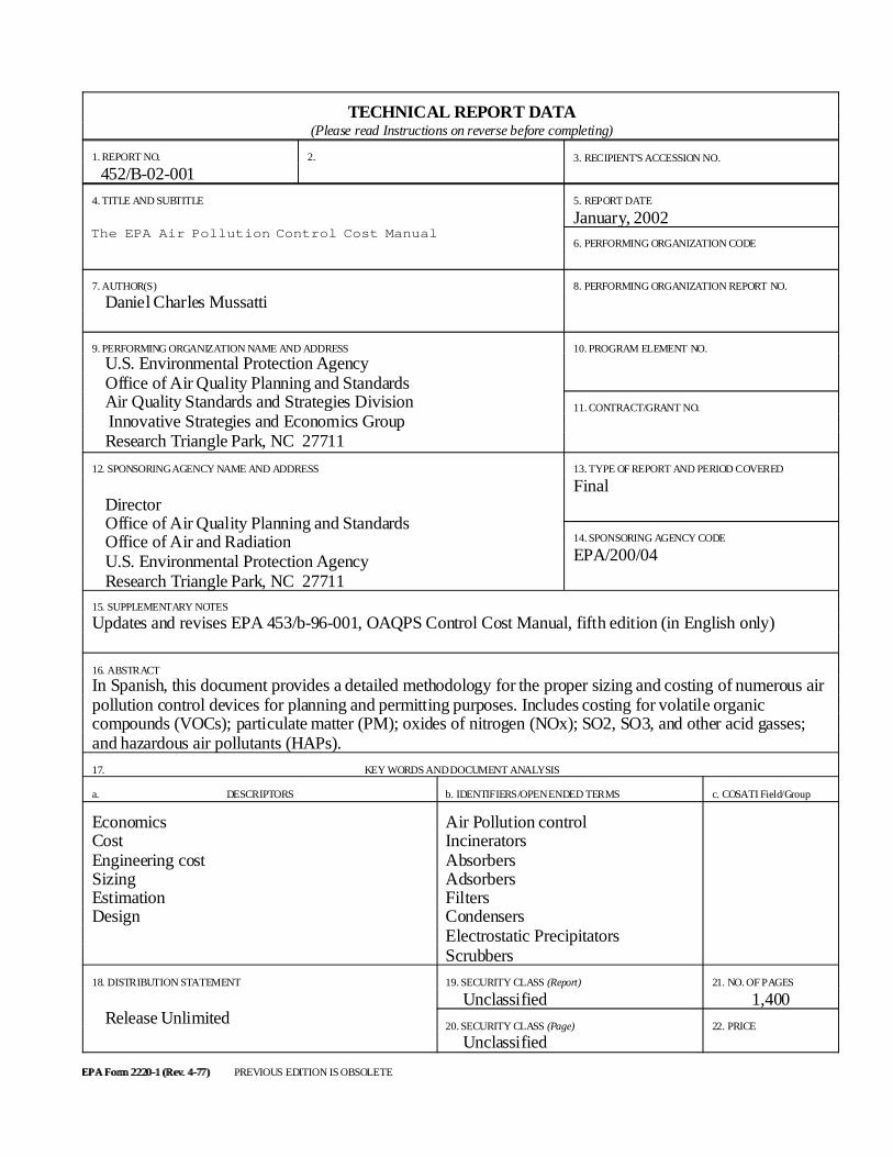
TECHNICAL REPORT DATA(Please read Instructions on reverse before completing)
1. REPORT NO.
452/B-02-0012. 3. RECIPIENT'S ACCESSION NO.
4. TITLE AND SUBTITLE
The EPA Air Pollution Control Cost Manual
5. REPORT DATE
January, 2002 6. PERFORMING ORGANIZATION CODE
7. AUTHOR(S)
Daniel Charles Mussatti
8. PERFORMING ORGANIZATION REPORT NO.
9. PERFORMING ORGANIZATION NAME AND ADDRESS
U.S. Environmental Protection Agency Office of Air Quality Planning and Standards Air Quality Standards and Strategies Division Innovative Strategies and Economics Group Research Triangle Park, NC 27711
10. PROGRAM ELEMENT NO.
11. CONTRACT/GRANT NO.
12. SPONSORING AGENCY NAME AND ADDRESS
Director Office of Air Quality Planning and Standards Office of Air and Radiation U.S. Environmental Protection Agency Research Triangle Park, NC 27711
13. TYPE OF REPORT AND PERIOD COVERED
Final
14. SPONSORING AGENCY CODE
EPA/200/04
15. SUPPLEMENTARY NOTES
Updates and revises EPA 453/b-96-001, OAQPS Control Cost Manual, fifth edition (in English only)
16. ABSTRACT
In Spanish, this document provides a detailed methodology for the proper sizing and costing of numerous airpollution control devices for planning and permitting purposes. Includes costing for volatile organiccompounds (VOCs); particulate matter (PM); oxides of nitrogen (NOx); SO2, SO3, and other acid gasses;and hazardous air pollutants (HAPs).
17. KEY WORDS AND DOCUMENT ANALYSIS
a. DESCRIPTORS b. IDENTIFIERS/OPEN ENDED TERMS c. COSATI Field/Group
EconomicsCostEngineering costSizingEstimationDesign
Air Pollution controlIncineratorsAbsorbersAdsorbersFiltersCondensersElectrostatic PrecipitatorsScrubbers
18. DISTRIBUTION STATEMENT
Release Unlimited
19. SECURITY CLASS (Report)
Unclassified21. NO. OF PAGES
1,400
20. SECURITY CLASS (Page)
Unclassified22. PRICE
EPA Form 2220-1 (Rev. 4-77)EPA Form 2220-1 (Rev. 4-77) PREVIOUS EDITION IS OBSOLETE